INSTRUCTION MANUAL DN0137 REVISION F Domestic ® Pump Vacuum and Boiler Feed Units Series VCMD TM

Welcome message from author
This document is posted to help you gain knowledge. Please leave a comment to let me know what you think about it! Share it to your friends and learn new things together.
Transcript
INSTRUCTION MANUAL DN0137
REVISION F
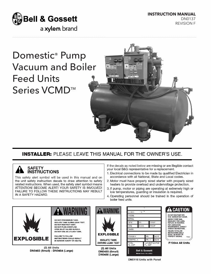
Domestic® Pump Vacuum and Boiler Feed Units Series VCMDTM


DESCRIPTIONThe Series VCMD family of units consists of various combinations ofboiler feed units combined with Domestic Series MJ vacuum pro-ducers. The vacuum producer may be mounted directly on the boilerfeed unit (STyle A) or the units may be independently mounted with fieldpiping between the units (Style B). The boiler feed units can be con-structed with cast iron or steel receivers in many of the standard con-figurations offered as Domestic boiler feed units.
The vacuum producer acts in response to selector switch settings andsystem vacuum also functions to remove excess water from the boilerfeed tank. Various controls are supplied in accordance with systemspecifications and system requirements. Electrical panels are normallysupplied and specific wiring diagrams are supplied with each vacuumproducer electrical panel.
The boiler feed system functions like a standard vented boiler feed sys-tem. Again, various control options are available to match systemspecifications. Electrical panels and electrical diagrams are normallyfurnished.
The boiler feed units are designed to pump water into an operatingboiler. The pumps are controlled by level controls on the boiler. Lowwater cut-off switches and alarms are often supplied (optional).
Receivers are non-code cast iron or steel.
PRELIMINARY INSPECTION
Assure that there is no shipping damage.
Assure that nameplate ratings agree with job specifications and actualconditions.
HANDLING
Use caring in installing unit.
LOCATION
Place unit for easy access to all parts. Allow adequate space forservicing. Check ambient conditions.
NOTICE/TEMPERATURE LIMITS
Motors are designed to operate in 104°F max. ambient. Insulate orventilate as required.
BOILER FEED SYSTEM
PIPING (General)
Pipe the unit per the Piping Diagram. Locate and support piping so asto not load the pump discharge.
PIPING (Return)
Gravity return lines from the system must be properly pitched down tounit inlet. Returns must also be trapped to prevent steam entry into theunit. An inlet basket strainer is recommended.
FLOAT SWITCHES
Floats are locked in place to prevent damage during shipment. Removeshipping locks. Check factory settings. Floats are adjustable for variouslevels of operation. The water make-up float switch should “make” at ahigher level than low water cut-off switch “breaks”.
VACUUM SYSTEMPIPING (General)
Pipe the unit per the Piping Diagram shipped with the unit or as shownherein. Locate and support piping so as to not load the pump discharge.
PIPING (Suction) (Style B)
Use a suction line at least as large as the unit inlet fitting. Vacuumstorage tanks will reduce system surges or short cycling and a verticaltank can trap liquids and solids.
PIPING (Vent)
Install a vent pipe to atmosphere. Pipe to be size of vent port on unit.Do not restrict or reduce vent opening or exceed 20 feet vertical heightunless an overflow connection is provided.
PIPING (Overflow)
Pipe overflow port to drain.
VACUUM SWITCH ADJUSTMENTS
Vacuum switches, when furnished, are factory adjusted and tested forthe specified operating range. If settings must be readjusted, refer tomanufacturer’s instructions.
HURLING WATER MAKE-UP AND CONTROL
The hurling water level is automatically controlled by a solenoid valveactuated by a float switch.
Connect the water make-up assemblies to city water. Use piping atleast as large as the valve piping provided. Install a manual fill valve ifnot included on the unit. The vacuum producer and the boiler feed unithave separate make-ups.
To operate at a high vacuum, the hurling water must be at a low tem-perature resulting in a low vapor pressure. Cooling water can be auto-matically admitted by using an optional temperature limit switch. Thisswitch actuates the solenoid valve if the temperature rises above apreset point.
The optional condensate Temperature Limit Switch will stop normaloperation of the vacuum unit when condensate exceeds the set pointtemperature (usually 160ºF). Vacuum is not normally required when thesystem is up to temperature and operation of the vacuum pumps withhot condensate results in condensate loss due to evaporation.
INTERCONNECTING PIPING
On style B units, the interconnecting piping between the boiler feedunit and the vacuum producer must be the size of the vacuum pro-ducer inlet. The two vacuum inlets on duplex vacuum producers mustbe connected to the boiler feed tank.
ELECTRICAL WIRING & CONTROLS
Connect power wiring per NEC. Recheck nameplate vs. Specificationsand conditions. All single phase motors have internal thermalprotection.
Three phase motors must be use starters with properly sized overloadrelays. Overload relays furnished are designed for manual reset.
EQUALIZING LINE
A vacuum may be formed on radiation side of system when steamstops flowing in mains. This vacuum may be higher than return linevacuum, which would prevent condensate from flowing back to pump.To correct this in an unzoned system, install equalizer line as shown inFigures 1 thru 3. To correct this in a zoned system, also install equali-zer line for each zoned section or install a vacuum breaker on supplyline on radiation side of each zone valve.
WARNING: EXPLOSIBLEDo not pressurize receiver. Isolate receiver during leak test.
Do not plug overflow. Do not restrict vent opening to atmosphere.Open valves slowly. Failure to follow these instructions could resultin serious injury or death.
3
CAUTION: UNIT LIFTING EYEUse unit lifting eyes only to lift unit as shipped from factory.
Unit must be empty and disconnected from pipes, anchors andother restraints. Use proper rigging procedures. Failure to followthese instructions could result in injury or property damage.
CAUTION: NOT A CHEMICAL PUMPInject boiler feed compounds from chemical feed tank into
boiler feed piping – never into condensate tank. Failure to followthese instructions could result in injury or property damage.
WARNING: HIGH VOLTAGE ELECTRICITYDisconnect and lock out power before connecting or servic-
ing unit. Failure to follow these instructions could result in injury orproperty damage.
FIG. 4 EQUALIZING CONNECTIONS FOR ZONED SYSTEMS
ZONE CONTROLVALVE
STEAM MAIN
M
TO ZONE
RETURN MAIN


HURLING CHAMBER FLOAT SWITCH ADJUSTMENT
The switch which controls the hurling water makeup valve is locatedinside the float housing near the vacuum unit overflow.
The switch is under a triangular cover plate which is retained by one #6screw (loosen bolts retaining the cover edges only if necessary). Theactuating cam can be rotated for testing by using a screwdriver in theslot provided.
Adjusting the switch location so that the switch snaps at approxi-mately mid-range of the cam travel. The #6 screw near the cam goesthru a slot in the switch mounting plate. Loosen this screw (and thefarthermost screw thru the switch) to permit adjustment of the switch-ing position. Tighten screws and recheck operation after making anyadjustment.
The cam should be positioned on the shaft for maximum switch rollermovement in operation. The cam is retained by a socket set screw.
Replacement seal tube assemblies are available in case of leakagearound the float pivot shaft.
OPERATION AND MAINTENANCEOperators must be familiar with all sections of this manual to under-stand the operation of the unit.
Hot water, steam and electricity can be hazardous.
LUBRICATION
The only pump bearing requiring lubrication is the ball bearing in themotor support just below the flexible coupling. It has a reservoir, whichis filled with moisture resistant high temperature grease.
Remove pipe plug in motor support and add approximately 3 ouncesof Shell Alvania RL 2 grease (or equivalent) from once a year (normal)to twice a year for extremely hot conditions. Do not use ordinarygrease.
NOTICE/AUTO RESTART
Single phase motors will restart automatically after thermal overloadprotector trips.
Overload thermal relays in starters must be reset manually.
GAGE GLASS MAINTENANCE (Vented Systems)
Clean gage glass as required using commercial glass cleaner. Dilutemuratic acid may be used if required (observe handling precautions).Never clean gage glass with wire brushes, scrapers or harsh abrasives.
Do not reuse gage glass or packing or seals.
Immediately replace glass which is broken, cracked, chipped,scratched or otherwise damaged. Inspect periodically with a brightconcentrated light. Anything which glistens and catches the fingernailor any star-shaped or crescent-shaped mark which glistens is causefor replacement. Any gage glass which appears cloudy or roughenedand will not respond to cleaning procedures should be replaced.
When replacing gage glass, use new packings specified for this use.Install glass with sufficient end clearance for expansion (keep glass tometal clearance at each end) and tighten nuts just enough to avoidleakage (do not over tighten).
INSPECTIONS
A properly installed unit should function unattended for long periods oftime. Periodic checks to assure proper operation are highly recom-mended. Refer to trouble shooting section when necessary.
A variety of control options are available and are furnished in accor-dance with user specifications. Refer to wiring diagrams (when fur-nished) to determine control switch settings.
The inlet strainer (when furnished) is intended to protect the pump andsystem. Periodic cleaning should be included in the maintenanceschedule. Check frequently in new systems.
WARNING: EXPLOSIBLEThe installer boiler feed unit becomes an integral part of the
boiler system. Boiler operation and maintenance requires specificskills and training and may require licensing or certification. Theboiler feed unit must be operated and maintained so as not to jeop-ardize the boiler operation. Failure to follow these instructions couldresult in serious injury or death.
WARNING: EXPLOSIBLEDo not pressurize receiver. Isolate receiver during leak test.
Do not plug overflow. Do not restrict vent opening to atmosphere.Open valves slowly. Failure to follow these instructions could resultin serious injury or death.
5
12. Check that the pump discharge pressure exceeds the maximumoperating pressure of the boiler.
13. Manually move the make-up water float indicator and assure thatthe make-up solenoid admits water.
14. Manually move the low water cut-off float switch indicator to checkfor pump shut-off.
15. Make sure that the make-up valve on the vacuum producer hasoperated and filled the hurling chamber to 2" to 6" below the over-flow (recommended).
16. Remove start-up label (below) from panel (if applicable) after com-plying with instructions.
17. If possible, observe operation thru several cycles.CAUTION: DO NOT RUN DRY.
SEAL DAMAGE MAY OCCURInspect pump seal regularly for leaks. Replace as required. Failureto follow these instructions could result in injury or propertydamage.
ELECTRICIAN/INSTALLER/OPERATORREMOVE AND DESTROY THIS TAG AFTER —1. ASSURING THAT ALL PUMPS ROTATE CLOCKWISE PER ARROWS CAST
ON VOLUTES. (JOG PUMP MOMENTARILY TO TEST – INTERCHANGEANY TWO MOTOR POWER WIRES TO REVERSE 3PH MOTORS.)
2. ASSURING THAT SHIPPING LOCKS HAVE BEEN REMOVED FROM ALLFLOAT SWITCHES.
WARNING: HIGH VOLTAGEDisconnect and lock out power before connecting or servic-
ing unit. Failure to follow these instructions could result in seriousinjury or death.
CAUTION: SUBSEQUENT DAMAGEA unit showing symptoms of possible problems (overflow,
noise, leaks, vibrations, continual operation, etc.) must be correctedimmediately. Failure to follow these instructions may result in full lia-bility for subsequent injury or property damage.
SAFETY INSTRUCTIONSSEE COVER OF THIS MANUAL
FLOAT ROD
MICRO SWITCH
CAMFLOAT BALL
CAM SETSCREW

6
All units are thoroughly tested at the factory before shipment. Theyshould operate satisfactorily without further adjustment if properlyinstalled and providing they have not been damaged by rough handlingin transit. If system or unit performance is not satisfactory, refer to thefollowing check list.
PUMP WILL NOT START1. The power supply has been interrupted, disconnect switch is open,
or selector switch is improperly positioned.2. Incorrect voltage for motor. Check voltage and wiring with motor
characteristics.3. Incorrect starter coil for power supply.4. The overload relays in the starter have tripped out and must be
reset. Ambient temperature may be too high.5. Check pump controls or other controls for proper operation.6. Wiring to control cabinet is incorrect or connections are loose.7. The strainer is dirty thus retarding flow. Clean periodically.8. Boiler is full or boiler control switch is defective.9. The low water cut-off float switch is open due to low water, incor-
rect adjustment or failure of makeup system.
PUMP RUNS CONTINUOUSLY1. Pump is running backward. Rotation of three phase motor may be
corrected by interchanging any two of the three wires. Rotationshould be clockwise looking down on motor.
2. Steam traps are blowing through causing condensate to return atexcessive temperatures. This may reduce the capacity of pumpbelow its rating, depending on the unit and type of pump furnished.Traps should be repaired or replaced.
3. Pump discharge pressure is less than operating pressure of theboiler.
4. The total required pressure at the pump discharge is greater thanthe pressure for which the pump was designed. Check the totalpressure which includes atmospheric pressure, the friction headand static head.
5. A valve in the discharge line is closed or throttled too tightly. Checkvalve is installed backwards.
6. The impeller eye is clogged.7. Pump is too small for system.
PUMP IS NOISY1. The pump is working against a lower pressure than designed for.
While pump is discharging, adjust plug cock in discharge line untilpressure at pump approaches pump rated pressure.
2. Excessive condensate temperature. Correct system conditions.However, this applies to certain units only; others are designed tohandle boiling water.
3. The piping is too small to drain properly.4. A defective trap is holding condensate in steam supply line.5. Pump is running backward.
THE SYSTEM IS NOISY
1. Banging in the steam mains is usually caused by steam “imploding”in condensate lying in low points in lines. These problems can beeliminated by dripping low points, properly supporting the pipe, orby increasing the pitch of the line.
2. Improper dripping of the steam mains and risers; where there is arise in the steam main, or where it branches off into a riser, a driptrap must be installed in the drain line.
3. The piping is too small to drain properly.4. A defective trap is holding condensate in steam supply line.5. Defective check valve permits steam to vent thru pump into the
boiler feed tank.6. Steam blowing thru a defective trap.7. A priming boiler is discharging water with the steam. Consult boiler
manufacturer.
TROUBLE SHOOTING PROCEDURES - BOILER FEED SYSTEM
PUMP WILL NOT START1. The power supply has been interrupted, disconnect switch is open,
or selector switch is improperly positioned.2. Incorrect voltage for motor. Check voltage and wiring with motor
characteristics.3. Incorrect starter coil for power supply.4. The overload relays in the starter have tripped out and must be
reset. Ambient temperature may be too high.5. Check pump controls or other controls for proper operation.6. Wiring to control cabinet is incorrect or connections are loose.7. System has vacuum and vacuum switches are open.8. Temperature limit switch open due to high condensate temperature.9. Temperature limit switch improperly wired.
PUMP RUNS CONTINUOUSLY1. Pump is running backward. Rotation of three phase motor may be
corrected by interchanging any two of the three wires. Rotationshould be clockwise looking down on motor.
2. System flow or leaks prevent the unit from developing design vac-uum. Vacuum system must be tight.
3. System is drawing vacuum greater than the vapor pressure of liquid– the liquid is being boiled and then condensed in the vacuum unit.
4. Holes in the nozzle plate are plugged or worn and the system willnot develop vacuum. Inspect and clean nozzle plates.
SYSTEM OVERFLOWS1. System may be normal. Cooling water is required to lower vapor
pressure of hurling water to be able to draw deep vacuum.2. Temperature limit switch is set lower than required and adds unnec-
essary water.3. The design vacuum is greater than the vapor pressure of a liquid
within the system. The liquid is being boiled from the system andcondensed in the hurling chamber.
4. Temperature limit switch is wired incorrectly.5. Float switch is improperly adjusted. Remove float switch cover
plate and readjust the cam activating the electrical switch.6. Boiler feed receiver sized too small to accommodate system
surges.7. water make-up valve open or float switch set too high.8. Water make-up valve leaks.
SYSTEM STARTS AND STOPS RAPIDLY1. Pumping against a small closed system. Add vacuum storage tank
or reset vacuum switches.
BOTH PUMPS RUN1. Improper vacuum switch adjustment. Readjust lead vacuum switch
to make and break at deeper vacuums than the lag switch. Refer tomanufacturers’ literature.
2. Low vacuum in system causing lag system switch to be closed.
TROUBLE SHOOTING PROCEDURES - VACUUM PRODUCER

These close coupled vertical centrifugal pumps are equipped withmechanical seals. If system has not been properly cleaned prior toinstallation of pump, foreign matter such as dirt, pipe scale, core sand,etc. may clog the impeller and damage the seal. A strainer is recom-mended in return line to pump. Pump must not be operated dry. Sealsmay be damaged if operated without water present.
1. Close inlet line gate valve and operate pump momentarily toremove as much liquid as possible from pump. Close dischargeline gate valve.
2. Shut-off and lock-out power.
3. Disconnect wiring to motor.
4. Make sure unit is cool enough that pump can be handled safely.Open receiver drain to remove remaining liquid.
5. Loosen the motor to pump volute fasteners. Assure that pressureis relieved per caution note.
6. Remove four capscrews (7) holding pump case to motor and liftmotor and impeller out of pump case.
7. Remove pump/motor assembly and place on work bench.
8. Prevent the motor shaft from turning by inserting a large screw-driver into the screwdriver slot located under the plug on the rearmotor endbell. Back the impeller off (counter clockwise) using arectangular bar or other flat tool inserted between the impellervanes.
9. Remove the rotating part of the mechanical seal from the end ofthe shaft.
10. Remove seal holder (2) with stationary ceramic part of mechanicalseal and cup rubber from the end of the shaft.
11. Remove stationary ceramic part of mechanical seal and cup rub-ber from recess in seal holder.
12. To install new seal, proceed as follows: Clean recess in sealholder thoroughly. Orient motor so that conduit opening on motoris to the left midway between motor lugs. Replace seal holder onthe face of the motor maintaining concentricity with motor face.Place new ceramic part of seal in the cup rubber over motor shaftand press firmly into recess of seal holder by hand, making certainboth parts bottom evenly. If assembly cannot be bottomed withfingers place a wooden or cardboard tube over shaft ontoceramic and push into place. Using a clean, lint-free cloth, wipe themating surfaces of the seal clean of any foreign matter. Moisten thecarbon section of the rotating part of the seal and place onto shaftto seat against the ceramic. Place seal spring onto shaft.
13. Hold motor shaft as described in #8 and replace the impeller on theshaft (clockwise rotation) making sure it is tight.
14. Orient motor for pump reassembly with conduit opening to the left.When mounting the pump case, discharge should be 90˚ to theright of the conduit opening on motor. Use care to insure tightgasket fit to prevent water leakage. When replacing pump case, thewire spacer eye should seat in pump case notch for fit up. If thisdoes not occur inspect for proper alignment and reassemble.
15. Replace four capscrews (7). Tighten down capscrews evenly toavoid damage.
16. Reconnect pump bleed line (where applicable) and motor wiring.
17. Close drain and slowly open inlet valves. See warning.
18. Jog to check motor rotation. See caution.
19. Observe operation thru several cycles.
1. Motor2. Seal Holder3. Seal4. Impeller
5. Gasket6. Case7. Capscrew
(motor tovolute)
8. Wear Ring9. Pipe Plug
10. Slinger
2DPF01
WARNING: EXPLOSIBLEDo not pressurize receiver. Isolate receiver during leak test.
Do not plug overflow. Do not restrict vent opening to atmosphere.Open valves slowly. Failure to follow these instructions could resultin serious injury or death.
7
WARNING / HIGH VOLTAGE: Disconnect and lockout power before connecting or servicing unit. Failure to
follow these instructions could result in serious injury or death.
CAUTION / PRESSURIZED SYSTEM: Operatingsystem may contain very hot water under pressure. Close
inlet and open drains before servicing. When servicing, loosenscrews and move components to assure pressure is relievedbefore removing screws. Keep drains open during servicing.Failure to follow these instructions could result in injury or propertydamage.
CAUTION / DO NOT RUN DRY.SEAL DAMAGE MAY OCCUR:
Inspect pump seal regularly for leaks. Replace as required. Failureto follow these instructions could result in injury or propertydamage.
CAUTION / DO NOT REVERSE: Reverse operationcan cause extensive damage to pumps. Jog the motor to
test for direction of rotation. Failure to follow these instructionscould result in injury or property damage.
1
10
7
3
4
8
6
9
5
2
PUMP SERVICE INSTRUCTIONS FOR SERIES C35,MODEL 609PF CENTRIFUGAL PUMPS
CAUTION / HOT SURFACES: Surfaces are hotwhen system is in operation. Do not touch hot re-
ceiver, let unit cool before servicing. Failure to follow theseinstructions could result in injury or property damage.

8
PUMP SERVICE INSTRUCTIONS FOR CENTRIFUGAL PUMPS (EXCEPT ‘B’ OR 609)Vertical mounting puts motor above floor direct and water
Close coupled centrifugal pumps are designed for years of trouble freeservice. Units have mechanical shaft seals.
1. Close inlet gate valve and operate pump momentarily to remove asmuch liquid as possible from pump. Close discharge line gatevalve.
2. Shut-off and lock out power.
3. Make sure unit is cool enough that pump can be handled safely.Open drain to remove remaining liquid.
4. Carefully remove pump drain plug and bleed line. Wait for com-plete drainage.
5. Loosen the motor bracket to pump volute capscrews. Assure thatthe pressure is relieved per caution note.
6. Complete the removal of the hardware. Remove pump/motorassembly and place on work bench.
7. Remove self locking stainless steel capscrews and stainless steelwasher (or self locking brass cap nut and washer) that secure theimpeller in place.
8. To remove impeller from motor shaft proceed as follows:
(1) Keyed Shafts. Remove impeller with gear puller or other meanswhich will not damage impeller or bend motor shaft.
(2) Threaded Shafts. Hold end of motor shaft opposite pump withlarge screwdriver or other suitable tool and back impeller offwith a rectangular bar or other flat tool inserted between thevanes of the impeller.
9. Remove rotating part of seal from shaft, being careful not breakcarbon face.
10. Remove capscrews holding motor bracket to motor and removebracket.
11. Remove stationary part of seal assembly, being careful not to chipor break ceramic seal.
12. To install seal proceed as follows:
(1) Clean recess in bracket thoroughly. Coat recess and “rubber”portion of seat with soap solution. Press seat into recess firmlyby hand making certain both parts bottom evenly. If seal can-not be bottomed with fingers place cardboard shipping disc onceramic and force into place with tool.
(2) Carefully place bracket in position on motor shaft withoutdisplacing ceramic seat and secure bracket to motor withcapscrews.
(3) Place motor vertically with pump end up. Do not attemptassembly of seal and impeller with shaft horizontal.
(4) The “carbon” of rotating part of seal should not be loose. If it is,hold in place with grease, Using clean, lint free cloth, wipemating surfaces perfectly clean. Soap shaft and push seal ontoshaft so that carbon will contact ceramic seal. If spacer isrequired, use grease to cause spacer to adhere to bottom ofseal after seal has been put on shaft, Be sure spacer is onlarger diameter of shaft so that will not catch between shoulderand impeller.
13. Replace impeller on shaft. Replace stainless steel washer andsecure impeller with capscrew or cap nut.
14. Place new gasket on pump volute and reassemble motor andpump subassembly on pump volute.
15. Reconnect pump bleed line and motor wiring.
16. Close drain and slowly open inlet valves. See warning.
17. Jog to check motor rotation. See caution.
18. Observe operation thru several cycles.
CAUTION: PRESSURIZED SYSTEMOperating system may contain very hot water. Close inlet
and open drains before servicing. When servicing, loosen screwsand move components to assure pressure is relieved before remov-ing screws. Keep drains open during servicing. Failure to followthese instructions could result in injury or death.
CAUTION: HOT SURFACESurfaces are hot when system is in operation. Do not touch
hot receiver, let unit cool before servicing. Failure to follow theseinstructions could result in serious injury or death.
WARNING: HIGH VOLTAGEDisconnect and lock out power before connecting servicing
unit. Failure to follow these instructions could result in serious injuryor death.
WATERSLINGER
VIEW OFTHREADEDIMPELLER
WEAR RING
IMPELLER2DPF03
VOLUTE
MOTOR BRACKET
MECHANICAL SEAL
WARNING: EXPLOSIBLEDo not pressurize receiver. Isolate receiver during leak test.
Do not plug overflow. Do not restrict vent opening to atmosphere.Open valves slowly. Failure to follow these instructions could resultin serious injury or death.
CAUTION: DO NOT REVERSEReverse operation can cause extensive damage to pumps.
Jog the motor to test for direction of rotation. Failure to follow theseinstructions could result in serious injury or death.
CAUTION: DO NOT RUN DRY.SEAL DAMAGE MAY OCCUR
Inspect pump seal regularly for leaks Replace as required. Failure to follow these instructions could result in serious injury ordeath.

9
1. Close pump isolation valve or system return line valve. Operatepump momentarily to discharge as much water as possible. Closepump discharge valve.
2. Shut-off and lock out power.
3. Make sure unit is cool enough that pump can be handled safely.Open drain to remove remaining liquid.
4. Carefully remove pump drain plug and bleed line. Wait for com-plete drainage.
5. Loosen both the discharge connection and the suction housing topump volute fasteners. Assure that the pressure is relieved percaution note.
6. Complete the removal of the hardware. Remove pump/motorassembly and place on work bench.
7a. Remove the suction housing capscrews and separate thepump/motor assembly from the suction housing. Note, the dif-fuser should separate from the suction housing to allow thepump/motor assembly to be removed.
(1) Threaded Motor Shafts (3Hp and less). Remove propeller locknut. Remove propeller with propeller stem as an assembly withthe diffuser. To install a new propeller, remove the propeller setscrews and separate from the stem.
(2) Keyed Motor Shafts (5Hp and larger). Remove propeller setscrews. Remove propeller, remove diffuser, and unscrew thepropeller stem.
7b. Remove propeller, propeller stem and diffuser from the assemblyas follows:
8. Remove capscrews holding motor bracket and pump volutetogether. Remove motor and bracket assembly from the volute bylifting straight away from volute.
9. To remove impeller from motor shaft proceed as follows:
(1) Keyed Shafts. Remove impeller with gear puller or other meanswhich will not damage impeller or bend motor shaft.
(2) Threaded Shafts. Hold end of motor shaft opposite pump withlarge screwdriver or other suitable tool and back impeller offwith a rectangular bar or other flat tool inserted between thevanes of the impeller.
10. Remove rotating part of seal from shaft, being careful not breakcarbon face.
11. Remove capscrews holding motor bracket to motor and removebracket.
12. Remove stationary part of seal assembly, being careful not to chipor break ceramic seal.
13. To install seal proceed as follows:
(1) Clean recess in bracket thoroughly. Coat recess and “rubber”portion of seat with soap solution. Press seat into recessfirmly by hand making certain both parts bottom evenly. If sealcannot be bottomed with fingers place cardboard shippingdisc on ceramic and force into place with flat tool.
(2) Carefully place bracket in position on motor shaft withoutdisplacing ceramic seat and secure bracket to motor withcapscrews.
(3) Place motor vertically with pump end up. Do not attemptassembly of seal and impeller with shaft horizontal.
(4) The “carbon” of rotating part of seal should not be loose. If itis, hold in place with grease, Using clean, lint free cloth, wipemating surfaces perfectly clean. Soap shaft and push seal ontoshaft so that carbon will contact ceramic seal. If spacer isrequired, use grease to cause spacer to adhere to bottom ofseal after seal has been put on shaft, Be sure spacer is onlarger diameter of shaft so that will not catch between shoulderand impeller.
14. Place impeller on shaft. Make sure impeller is seated.
15. Reassemble volute to bracket.
16. Install stem over drive pin in impeller eye. Tighten lock nut.
17. Set stem to .004 TIR.
CAUTION: PRESSURIZED SYSTEMOperating system may contain very hot water. Close inlet
and open drains before servicing. When servicing, loosen screwsand move components to assure pressure is relieved before remov-ing screws. Keep drains open during servicing. Failure to followthese instructions could result in injury or death.
CAUTION: HOT SURFACESurfaces are hot when system is in operation. Do not touch
hot receiver, let unit cool before servicing. Failure to follow theseinstructions could result in serious injury or death.
WARNING: HIGH VOLTAGEDisconnect and lock out power before connecting servicing
unit. Failure to follow these instructions could result in serious injuryor death.

Xylem Inc. 8200 N. Austin Avenue Morton Grove, Illinois 60053 Phone: (847) 966-3700 Fax: (847) 965-8379www.bellgossett.com
Bell & Gossett is a trademark of Xylem Inc. or one of its subsidiaries. © 2018 Xylem Inc. DN0137F March 2018
Related Documents