Technische Universität Wien DIPLOMARBEIT Erstellung eines photorealistischen 3D-Modells der Kirche San Juan del Hospital in Valencia ausgeführt am Institut für Photogrammetrie und Fernerkundung der Technischen Universität Wien unter der Leitung von Dr. Karl Kraus, Dr. Franz Rottensteiner, Dr. Helmut Kager durch Wilfried Karel 1070 Wien, Zieglergasse 84/4 Datum Unterschrift

Welcome message from author
This document is posted to help you gain knowledge. Please leave a comment to let me know what you think about it! Share it to your friends and learn new things together.
Transcript
Technische Universität Wien
DIPLOMARBEIT
Erstellung eines photorealistischen 3D-Modells der Kirche San Juan del Hospital in Valencia
ausgeführt am
Institut für Photogrammetrie und Fernerkundung
der Technischen Universität Wien
unter der Leitung von
Dr. Karl Kraus, Dr. Franz Rottensteiner, Dr. Helmut Kager
durch
Wilfried Karel 1070 Wien, Zieglergasse 84/4
Datum
Unterschrift
i
Contents 1 Abstract ........................................... 1 1.1 Extracto................................................. 2
2 Camera Calibration ................................. 3 2.1 Capture of Calibration Data.............................. 3 2.2 Evaluation............................................... 4 2.3 Tests on Interior Stability.............................. 6
3 Data Capture San Juan .............................. 9 3.1 Existing Data............................................ 9 3.1.1 Examination .............................................9 3.1.2 Selection of Data to Be Used ............................9
3.2 Geodetic Data Acquisition............................... 10 3.3 Photogrammetric Data Acquisition........................ 14 3.4 Non-Geometric Data Acquisition.......................... 16
4 The Hybrid Block .................................. 17 4.1 Polar Observations...................................... 17 4.2 Photogrammetric Observations............................ 19 4.2.1 Image Selection ........................................19 4.2.2 Interior Orientation ...................................23 4.2.3 Exterior Orientation ...................................24
4.3 Gestalt Observations.................................... 26 4.3.1 Symmetries .............................................28
4.4 Models.................................................. 32 4.5 Hybrid Block Adjustment................................. 32 4.5.1 Functional Model Finalization ..........................34 4.5.2 Stochastic Model Finalization ..........................37 4.5.3 Final Adjustment .......................................38
5 Modelling ......................................... 40 5.1 VRML97.................................................. 40 5.2 ORPHEUS Model Restrictions.............................. 40
ii
5.3 Web Requirements........................................ 41 5.4 Modelling San Juan...................................... 41 5.5 Image Enhancement....................................... 42
6 VRML Programming .................................. 44 6.1 Level of Detail......................................... 44 6.2 Animating the Point of View............................. 44 6.3 Non-Geometric Information............................... 45 6.4 Head-Up-Displays........................................ 45 6.5 Measurement Module...................................... 46 6.5.1 AVATAR Position and Attitude ...........................49 6.5.2 Quality Mode ...........................................50 6.5.3 Measure Line Mode ......................................51
6.6 Other Elements.......................................... 52 6.6.1 Help System ............................................52 6.6.2 Orthophoto as Underlay .................................53 6.6.3 Automatic Door .........................................53 6.6.4 Audio Scenery ..........................................53
6.7 Program Hierarchy....................................... 53 7 Conclusions ....................................... 57 Appendix ............................................ 59 A Nomenclature ...................................... 60 B Adjustment Protocol of the Camera Calibration..... 63 C Stability of the Camera’s Interior Orientation.... 67 C.1 Adjustment Protocol of the First Set of 15mm-Photos ..... 67 C.2 Adjustment Protocol of the Second Set of 15mm-Photos .... 70 C.3 Statistical Tests....................................... 72
Bibliography ........................................ 74 Acknowledgements .................................... 76 Curriculum Vitae .................................... 77 Additionally in this document’s printed version: Enlarged depiction of all used photogrammes’ interior and exterior orientations....................... end of this document Attached compact disc containing the photo model and the ORPHEUS project files... inside of this document’s back cover
1 ~ Abstract
1
1 Abstract Subject of this diploma thesis is the production of a photo model of the church of San Juan del Hospital and the pavilion beside, situated in Valencia, Spain. The work is done by the author of this paper, advised and guided by Dr. Karl Kraus, Dr. Franz Rottensteiner and Dr. Helmut Kager from the Institute of Photogrammetry and Remote Sensing, Vienna University of Technology, Austria, in collaboration with Dr. José Luis Lerma García from the Department of Cartographic Engineering, Geodesy and Photogrammetry, ETSIGCT, Polytechnic University of Valencia, Spain. The whole building and its surroundings are topic of the research program ‘Proyecto Rafael’ which was raised because of the fact that San Juan, built in 1238, is one of the very few Spanish churches of Romanesque style still remaining in that way. At the end of the ‘reconquista’ (722-1492), the re-conquest of Arabic Spain by Christian troops, the Romanesque style (ca. 950-1250) had already ceased to exist. So, very few buildings of this kind were constructed; furthermore, many of them were changed to gothic or baroque architectures. A big matter of interest in ‘Proyecto Rafael’ is the capture, classification, and calculation of data related to the physical properties of the historical site. Before the start of the project documented in this paper, many technicians, e.g. surveyors, geophysicists, and photogrammetrists have worked on the mentioned area where many data already have been produced. Still there does not exist a spatial model of the whole complex. On the one hand, this model shall enable anyone interested to view the state of the exterior appearance of the treated building during the time of data capture. On the other hand, it shall represent a geometric and photographic document of high accuracy that contains rectified images of the whole shape, which will allow forthcoming scientists to measure object positions and façade texture in case of building destructions, etc.
1 ~ Abstract
2
To fulfil the demands of both, VRML97 is selected as output format, as it permits dynamic visualization to a wide public on any internet browser and allows the usage of highly accurate data as well. The resulting VRML world can be accessed from the compact disc that is attached at the end of this document.
1.1 Extracto Esta tesis tiene como objetivo la elaboración de un foto modelo de la Iglesia de San Juan del Hospital y el Pabellón situado junto a la misma, localizados en Valencia, España. El trabajo está hecho por el autor de este papel, aconsejado y dirigido por Dr. Karl Kraus, Dr. Franz Rottensteiner y Dr. Helmut Kager del Instituto de Fotogrametría y Teledetección, Universidad Técnica de Viena, Austria, en colaboración con Dr. José Luis Lerma García del Departamento de Ingeniería Cartográfica, Geodésia y Fotogrametría, ETSIGCT, Universidad Politécnica de Valencia, España. El edificio entero y sus alrededores son asunto del programa de investigación ‘Proyecto Rafael’ que fue iniciado por el hecho de que la Iglesia de San Juan, construida en 1238, es una de las pocas iglesias del estilo Románico que quedan en España. El motivo por el cual existen pocos edificios de este estilo, es que fueron construidos al final de la Reconquista de la España árabe por parte de las tropas cristianas (722-1492), cuando el estilo Románico (ca. 950-1250) había dejado ya de existir. Además, posteriormente muchos de ellos fueron modificados hacia arquitecturas góticas o barrocas. Un gran tema de interés en el Proyecto Rafael es la captura, la clasificación y el cálculo de datos relacionados con las características físicas del sitio histórico. Antes del comienzo del proyecto documentado en este papel, muchos técnicos, p.ej. topógrafos, geofísicos y photogrametros han trabajado en el área mencionada, y muchos datos se han producido ya. Pero todavía no existe un modelo espacial del complejo del conjunto. Por un lado, este modelo permitirá a cualquier persona interesada ver el estado del aspecto exterior del edificio tratado durante la época de la recogida de datos. Por otra parte, representará un documento geométrico y fotográfico de alta precisión, conteniendo imágenes rectificadas de la forma entera, que permitirá que los siguientes científicos midan posiciones del objeto y textura de la fachada en el caso de destrucciones del edificio, etc. Para satisfacer las demandas de ambos, VRML97 se selecciona como formato de salida, porque permite la visualización dinámica a un público ancho en cualquier motor de búsqueda y permite también el uso de datos exactos.
2 ~ Camera Calibration
3
2 Camera Calibration For the capture of photographic data, there was a digital non-metric camera at the author’s disposal, brand Canon, Type EOS D60 with a resolution of 6.3MPx and a lens with a variable focal length of 15 to 30mm. To get to know the capture parameters of the instrument, there had to be done a calibration on a field of known control points, as the circumstances for an on-the-fly-calibration at the site of investigation are far away from being ideal. Camera parameters calculated in the adjustment of the hybrid block at San Juan would be little reliable, as it seems difficult to define exact pass- and tie-points on the object. Furthermore, usage of geometric relations between object points (‘Gestalts’) is recommended for economical reasons when calculating photo models, which could influence the resulting camera parameters adversely. Their detection would require big areas of the buildings’ surface covered by several photogrammes taken from different positions, which is a more or less impossible task in this case, as the whole site is very narrow in relation to the minimum focal length of the lens. In addition, photogrammes can only be taken from the ground in many places and data capture at San Juan has to be done rapidly, as religious activities must not be disturbed. Furthermore, as the used instrument is not a metric system, parameters are expected to vary more than on usually used cameras. Above all, the effects of the variable focal length, the adjustable focus, and the amateur camera case have to be examined.
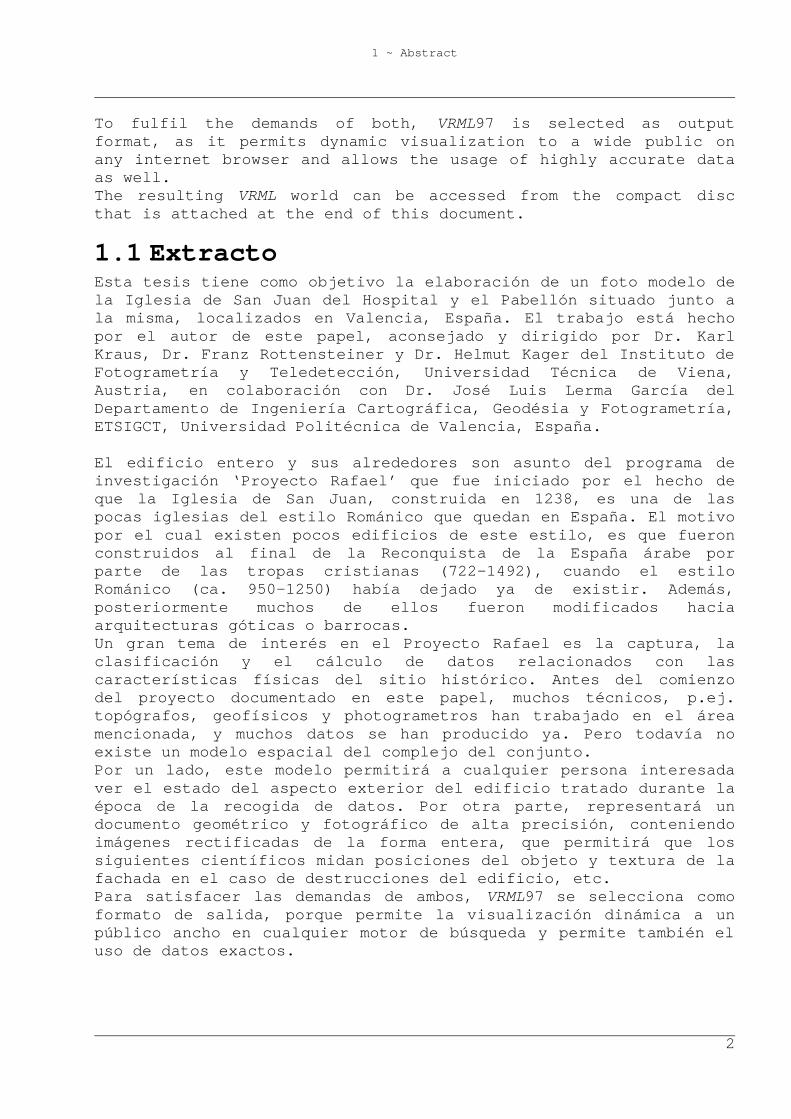
2.1 Capture of Calibration Data To solve the given problem, usage of the camera calibration test field at the ETSIGCT was decided. It consists of 45 points on two perpendicular façades made of metal elements (Fig. 2-1). Coordinates are given in millimetres with undetermined accuracy. The covered ground area is 20m x 18m, elevation ranges from 0m to 12m.
2 ~ Camera Calibration
4
Fig. 2-1: Calibration field at ETSIGCT, Technical University of Valencia.
Pictures were taken from different viewpoints on the yard and from different windows and the roof of a building facing the points of the calibration field. To detect parameter changes because of intermediate focal change, the focal length was altered from 15mm (10 pictures) to 30mm (4 pictures, only 3 used), back to 15mm (6), and back to 30mm again (2). Focus was kept fixed during the whole capture.
2.2 Evaluation The photogrammetric software package ORIENT/ORPHEUS of the Institute of Photogrammetry and Remote Sensing was used to do the measurement, definition and hybrid block adjustment of all observations and parameters, i.e. photo coordinates, control point coordinates, exterior photo orientations, camera parameters (interior orientations), and the corresponding stochastic model. The reference system of the block is defined by the control point coordinates. As already said, the existing control point data didn’t have accuracy given, so their standard deviation was set to 1cm a priori, since object points had been determined by tachymeter observations, spending high effort on good data quality. The precision of point measurements in photos was set to 0.5px a priori. Two interior orientations were defined, one for 15mm focal length, the other one for 30mm, where the projection centres were set perpendicular to the photo centre, in a distance of the focal length. These parameters only served as first approximations, as they were treated as free parameters in the adjustment.
2 ~ Camera Calibration
5
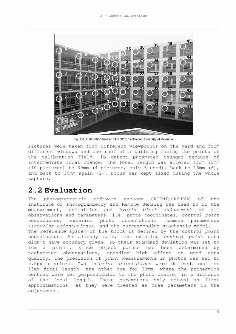
Now, three out of 45 obviously bad determined control points were deactivated (points 1, 3, 22). During the adjustments, interior and exterior orientations were calculated, additional distortion parameters (adp), too. These parameters should be linearly independent from each other and from the parameters of the exterior orientation [Kraus, 1996, p. 142]. The author decided to use the Torlegard distortion parameter set, which fulfils these requirements. Furthermore, it was assumed that it would not be advisable to use radial distortion parameters with degrees higher than the fifth, as they can only be determined well in images with large extents and small scales that were taken with metric cameras (e.g. aerial photogrammes). Therefore, the six parameters listed in Tab. 2-1 were considered as possible distortion parameters and were used in the first adjustment. adp id Geometric Meaning Distortion Function
dx0i(x,y) dy0i(x,y) 1 Skewness of Axes 0 x 2
Affinity Scaling of y-Axis 0 y
3 3rd degree x(r²-1) y(r²-1) 4
Radial Distortion 5th degree x(r4-1) y(r4-1)
5 r²+2x² 2xy 6
Tangential (Asymmetric) Distortion 2xy r²+2y²
Tab. 2-1: Considered Torlegard distortion parameters (adp).
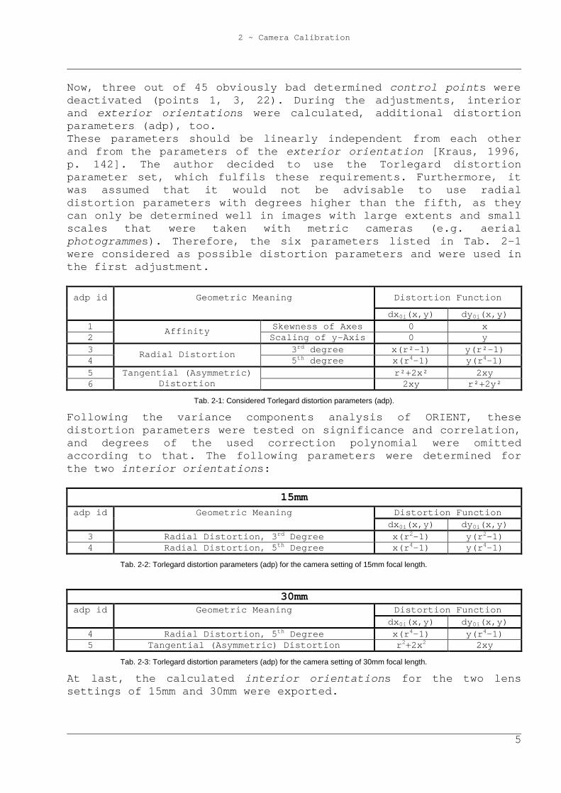
Following the variance components analysis of ORIENT, these distortion parameters were tested on significance and correlation, and degrees of the used correction polynomial were omitted according to that. The following parameters were determined for the two interior orientations:
15mm adp id Geometric Meaning Distortion Function
dx0i(x,y) dy0i(x,y) 3 Radial Distortion, 3rd Degree x(r2-1) y(r2-1) 4 Radial Distortion, 5th Degree x(r4-1) y(r4-1)
Tab. 2-2: Torlegard distortion parameters (adp) for the camera setting of 15mm focal length.
30mm adp id Geometric Meaning Distortion Function
dx0i(x,y) dy0i(x,y) 4 Radial Distortion, 5th Degree x(r4-1) y(r4-1) 5 Tangential (Asymmetric) Distortion r2+2x2 2xy
Tab. 2-3: Torlegard distortion parameters (adp) for the camera setting of 30mm focal length.
At last, the calculated interior orientations for the two lens settings of 15mm and 30mm were exported.
2 ~ Camera Calibration
6
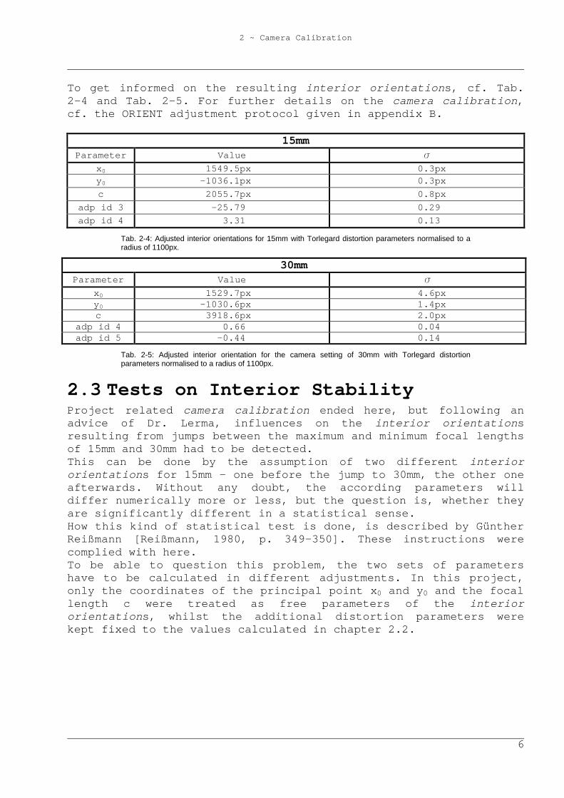
To get informed on the resulting interior orientations, cf. Tab. 2-4 and Tab. 2-5. For further details on the camera calibration, cf. the ORIENT adjustment protocol given in appendix B.
15mm Parameter Value s
x0 1549.5px 0.3px y0 -1036.1px 0.3px c 2055.7px 0.8px
adp id 3 -25.79 0.29 adp id 4 3.31 0.13
Tab. 2-4: Adjusted interior orientations for 15mm with Torlegard distortion parameters normalised to a radius of 1100px.
30mm Parameter Value s
x0 1529.7px 4.6px y0 -1030.6px 1.4px c 3918.6px 2.0px
adp id 4 0.66 0.04 adp id 5 -0.44 0.14
Tab. 2-5: Adjusted interior orientation for the camera setting of 30mm with Torlegard distortion parameters normalised to a radius of 1100px.
2.3 Tests on Interior Stability Project related camera calibration ended here, but following an advice of Dr. Lerma, influences on the interior orientations resulting from jumps between the maximum and minimum focal lengths of 15mm and 30mm had to be detected. This can be done by the assumption of two different interior orientations for 15mm – one before the jump to 30mm, the other one afterwards. Without any doubt, the according parameters will differ numerically more or less, but the question is, whether they are significantly different in a statistical sense. How this kind of statistical test is done, is described by Günther Reißmann [Reißmann, 1980, p. 349-350]. These instructions were complied with here. To be able to question this problem, the two sets of parameters have to be calculated in different adjustments. In this project, only the coordinates of the principal point x0 and y0 and the focal length c were treated as free parameters of the interior orientations, whilst the additional distortion parameters were kept fixed to the values calculated in chapter 2.2.
2 ~ Camera Calibration
7
)QQ(kk
sksk
mmt̂
221121
mmmm21
202
201
21
++
+
−=
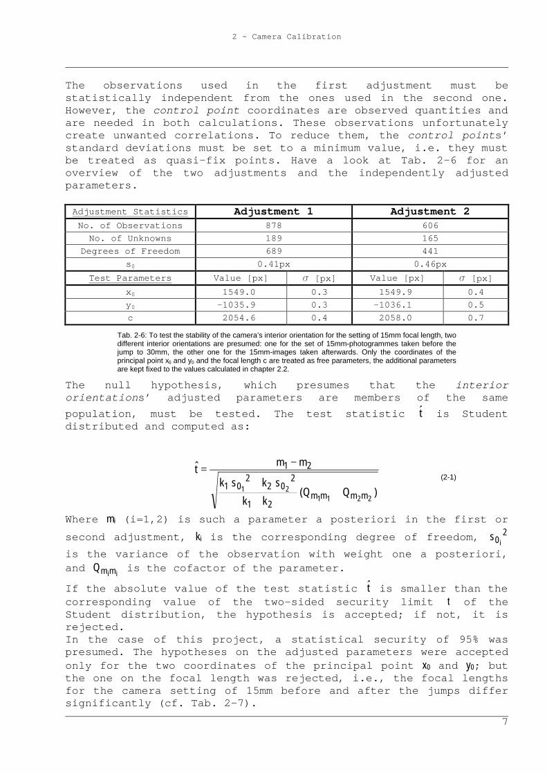
The observations used in the first adjustment must be statistically independent from the ones used in the second one. However, the control point coordinates are observed quantities and are needed in both calculations. These observations unfortunately create unwanted correlations. To reduce them, the control points’ standard deviations must be set to a minimum value, i.e. they must be treated as quasi-fix points. Have a look at Tab. 2-6 for an overview of the two adjustments and the independently adjusted parameters. Adjustment Statistics Adjustment 1 Adjustment 2 No. of Observations 878 606
No. of Unknowns 189 165 Degrees of Freedom 689 441
s0 0.41px 0.46px Test Parameters Value [px] s [px] Value [px] s [px]
x0 1549.0 0.3 1549.9 0.4 y0 -1035.9 0.3 -1036.1 0.5 c 2054.6 0.4 2058.0 0.7
Tab. 2-6: To test the stability of the camera’s interior orientation for the setting of 15mm focal length, two different interior orientations are presumed: one for the set of 15mm-photogrammes taken before the jump to 30mm, the other one for the 15mm-images taken afterwards. Only the coordinates of the principal point x0 and y0 and the focal length c are treated as free parameters, the additional parameters are kept fixed to the values calculated in chapter 2.2.
The null hypothesis, which presumes that the interior orientations’ adjusted parameters are members of the same population, must be tested. The test statistic t̂ is Student distributed and computed as:
(2-1)
Where mi (i=1,2) is such a parameter a posteriori in the first or second adjustment, ki is the corresponding degree of freedom, 2
0 is
is the variance of the observation with weight one a posteriori, and
iimmQ is the cofactor of the parameter.
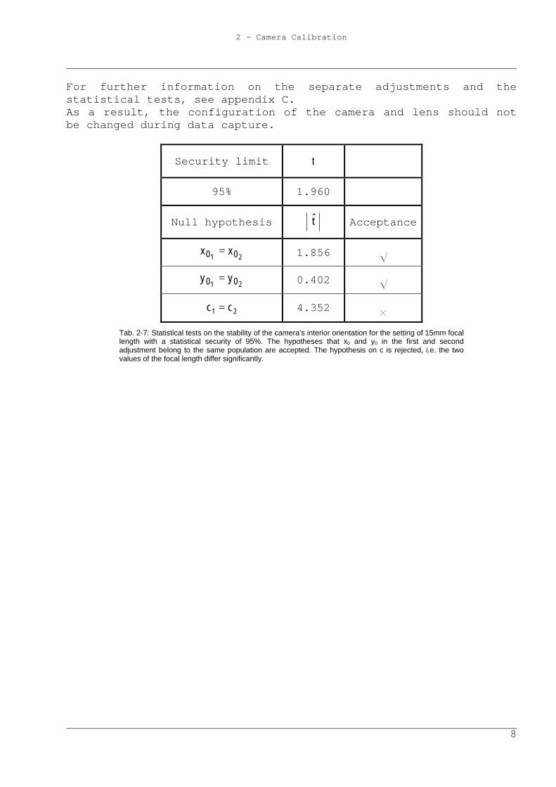
If the absolute value of the test statistic t̂ is smaller than the corresponding value of the two-sided security limit t of the Student distribution, the hypothesis is accepted; if not, it is rejected. In the case of this project, a statistical security of 95% was presumed. The hypotheses on the adjusted parameters were accepted only for the two coordinates of the principal point x0 and y0; but the one on the focal length was rejected, i.e., the focal lengths for the camera setting of 15mm before and after the jumps differ significantly (cf. Tab. 2-7).
2 ~ Camera Calibration
8
For further information on the separate adjustments and the statistical tests, see appendix C. As a result, the configuration of the camera and lens should not be changed during data capture.
Security limit t
95% 1.960
Null hypothesis t̂ Acceptance
21 00 xx = 1.856 S 21 00 yy = 0.402 S
21 cc = 4.352 G Tab. 2-7: Statistical tests on the stability of the camera’s interior orientation for the setting of 15mm focal length with a statistical security of 95%. The hypotheses that x0 and y0 in the first and second adjustment belong to the same population are accepted. The hypothesis on c is rejected, i.e. the two values of the focal length differ significantly.
3 ~ Data Capture San Juan
9
3 Data Capture San Juan
3.1 Existing Data As already said, many data concerning San Juan had already been produced by other scientists, and these had to be used as much as possible, to reduce redundant work, and accelerate the production of the photo model.
3.1.1 Examination Mentioned data was given to the author at the archive of Mrs. Ma Jesús Jiménez Martínez from the Department of Cartographic Engineering, Geodesy and Photogrammetry, ETSIGCT, Polytechnic University of Valencia, and at the church’s museum. They consist of:
- digital two-dimensional plans of the buildings and its surroundings in vector format
- digital two-dimensional plans of excavations of tombs and skeletons also as files in .dgn and .dwg-format
- non-metric photos of the restoration sites - one metric photo of a part of the building in black and white - a database of the excavations, containing archaeological
information - plans of some soil profiles examined with georadar - many technical and historical reports - brochures of the church, containing historical information
3.1.2 Selection of Data to Be Used The aim of usage of existing data was the reduction of work necessary to calculate the whole model, not only to reduce time in capturing new data.
3 ~ Data Capture San Juan
10
The two-dimensional digital plans did not fulfil this guideline, as there where some doubts about point definitions. Therefore, much work for verification could have resulted. Utilization of the one existing metric photo in black and white did not seem to help, as the model was expected to be in colour, and therefore it only could have served as geometric information. Moreover, digitizing this image would have required the calibration of a scanner. Finally, only the introduction of some historic information onto the modelled object from the brochures was planned. As an option in case of fast project progress, visualization of tombs and skeletons in the subsoil could have been installed.
3.2 Geodetic Data Acquisition Transformation of the whole model into the UTM coordinate system by geodetic measurements to known points of the Spanish national geodetic network would have been a non-economical effort, as one of the two national reference points next to the treated area is at a distance of more than one kilometre. The other one is situated at about 300m, on top of Valencia’s cathedral, where coordinates are said to be out of date, according to information from the Cartographic Institute of Valencia. The whole site is very narrow, exact point definition on the façade is quite difficult and time consuming, and many parts of the object cannot be photographed from various positions. Because of that, stabilization of the bundle block exclusively by tie-points would have required more work than the measurement and calculation of a local geodetic network and the determination of pass-points on the object derived from that. The author already had some experience on this geodetic technique, and so it was convenient to use the second option, the geodetic network. He used a tachymeter, brand Leica, type TC307, which provides an angular accuracy of 2mgon, in distance one of 2mm + 2ppm and a compensator precision of 0.7mgon. As this instrument does not permit reflectorless laser distance measurements, pass-points had to be determined by spatial intersections. As a result, the stations had to be chosen first, wherefrom every derived pass-point would be visible at least twice. The equipment for high accuracy measurements consisted of the instrument, three tripods, and two reflectors. Because of its weight and size, the transport to and from the site of investigation was rather complicated and therefore, the author began his work with the station network. This way, the transfer problem would be solved, once all stations would be marked out and determined.
3 ~ Data Capture San Juan
11
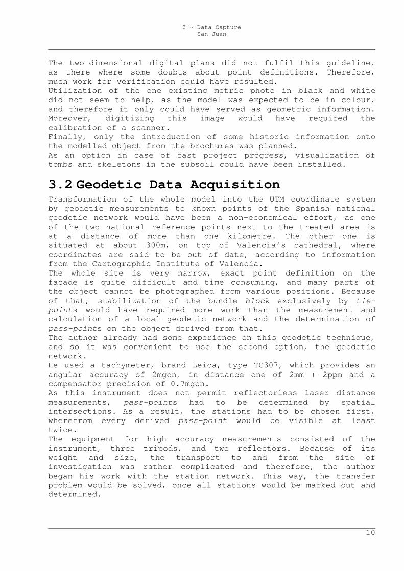
A detail of ORIENT had to be borne in mind. That is the recommendation to set the attitude of the instrument’s horizontal zero-direction on every station parallel to the x-axis of the global reference system, approximately. As magnetic North was roughly parallel to that again, the setting could be done with the help of the bearing of a compass. It is not possible to walk around the church, as its East is delimited by a street and its northern and south-eastern yards are separated from that street by another building with a closable corridor for visitants or by a wall with a gate, respectively. In addition, its West is connected to an even higher building, and the south-western yard is split from its eastern part by a wall, as well. Especially during the measurement of the station network, the working schedule had to be organized well, as changing positions was necessary more often than during the following pass-point measurement, and access to the surroundings of the church had to be asked for in advance. To get a better idea of these difficulties and for a look at the resulting station and remote target network, cf. Fig. 3-1.
3 ~ Data Capture San Juan
12
Fig. 3-1: Station and remote target network around the modelled buildings.
Most time was spent on the selection of stations, on getting access to them and on the sketches of the object. As a result, concerning the measurement of the pass-points, it was obvious that the determination of some points more or some less would not influence working time much.
3 ~ Data Capture San Juan
13
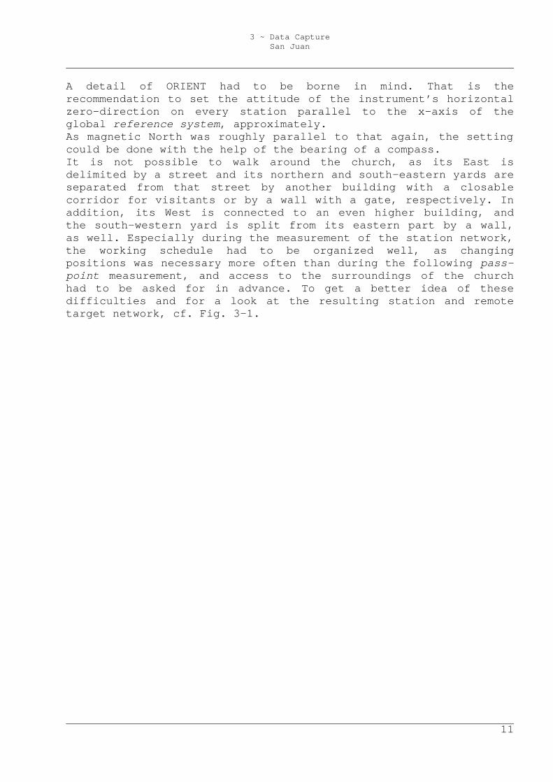
Apparently, it would be a big advantage to be able to calculate the approximate exterior orientations of the photogrammes to be taken later without unknown tie-points, as this type of calculation can be done with a spatial resection called ‘Müller-Killian’, which is implemented in ORIENT/ORPHEUS. This calculus makes manual photo orientation needless, but it requires at least four known points in each picture. It can be a quite difficult and time-consuming job to select the appropriate photos to be used in the model, especially on surfaces without much structure, where it is not clear if, where, or how much two photos overlay each other. This is essential for texture transfer, if a part of the façade is hidden in one image by an object that should not appear in the model and thus must be visible in the other photogramme (see Fig.3-2). If the Müller-Killian algorithm can be used to calculate approximate orientations, replacing a photo by another only means measuring the photo coordinates of four or more known pass-points in the new image. Otherwise, in case of tie-point usage for photo orientation, if the worst comes to the worst, after the substitution, formerly known tie-points can get ‘out of range’ (the adjustment does not converge any more) because of inaccurate manual photo orientation, or get undetermined in case of invisibility (singularities appear, the adjustment cannot be calculated any longer).
Fig.3-2: Without knowledge of the exterior orientations it can hardly be said, whether the point marked witch a red circle, which lies at the edge of the visible area of the façade in the photo on the left, is hidden in the image on the right.
Because of that, many pass-points were determined: 184 by number, well distributed in all three dimensions all over the surfaces, each one observed from 2.9 stations on average. Captured data was transferred to the operator’s PC. For the following treatment of polar observations, see chapter 4.1.
3 ~ Data Capture San Juan
14
3.3 Photogrammetric Data Acquisition Having in mind the determined pass-points, taking photogrammes began. Images taken with the used camera in CANON-RAW-format (lossless compression), with the maximum resolution of 3072px x 2048px and a colour depth of 24 bits occupy about 7MB of memory each. The instrument allocates a memory of 1.2GB. Therefore, there can be stored 175 images, approximately, without the need to return to a PC to transfer them to mass storage. As there was neither a stepladder, nor a crane, an aircraft or a balloon available, images could only be taken from places that were reachable on foot, in a range from the bottom until about 2m of height. Hence, many parts of the buildings could not be seen from different positions and the obligation to use numerous mathematical object shape relations in the hybrid block already was predictable. As memory space did not seem to limit the number of taken images too much, mentioned RAW format was chosen, as it permits picture enhancement without loss of information. Besides, especially in places where special permission and accompaniment were required, many photos were taken. Of course, there had to be made a decision on the handling of the camera itself, too. This includes change of focal length, focus, and aperture; obviously, not all necessary pictures could be taken on the same day, and the camera had to be packed in its case throughout the walks between the places of exposure. Thus, the ability to recover the interior orientation several times was a big question. First, usage of two different settings of the focal lengths was rejected, as there had resulted statistically proven changes in interior orientation parameters after focal length alteration in the adjustments of the camera calibration (see chapter 2.3). Motorized focal length and focus change was deactivated. Moreover, the author decided to turn the focus ring to the limit at the infinity sign, and the zoom ring to the limit at 15mm, as 30mm seemed too much in comparison to the narrow site. Equipped with a camera tripod, it was clear then to take pictures with the minimal lens aperture that still allowed exposure times of less than approximately one second, depending on the tripod height, the strength of the wind at the very moment, and the stability of the ground under the tripod. That is, because the smaller the aperture, the smaller the blur. Having the focus set to infinity, the blur circle diameter u can be calculated with (3-1), depending on the focal length f, the aperture k, and the distance from the projection centre to the object point g.
(3-1) kg
fu
2=
3 ~ Data Capture San Juan
15
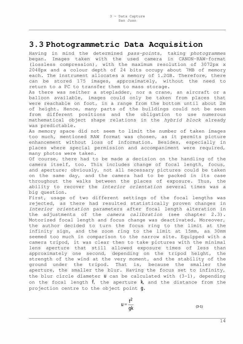
Given the focal length of 15mm, having the focus set to infinity and presuming a maximum blur of 3px (estimated image coordinate measurement standard deviation), selecting small apertures becomes important when object points are in a distance smaller than about 3m (cf. Fig. 3-3). Especially during the data capture concerning the pavilion, this issue got essential, as some parts of its interior could not be photographed from further than 2.5m.
Fig. 3-3: Blur as a bivariate function of the distance to the object and the aperture, given a focal length of 15mm and having the focus set to infinity. Presuming a maximum blur of 3px, selecting small apertures becomes important when object points are in a distance smaller than about 3m.
Finally, in the first photo session during two days there were taken 226 pictures. As model production advanced, the operator discovered that several existing photogrammes should have imaged slightly different pieces of the objects, to be able to reduce the number of necessary ones. Moreover, he revealed that some parts of the buildings were not visible at all, that few images were not readable, and that a number of them had been shot at bright sunlight, which resulted in hard shadows.

3 ~ Data Capture San Juan
16
Thus, a second photo session had to be made, this time on a day with adequate foggy, but still bright weather. 118 images resulted.
3.4 Non-Geometric Data Acquisition The aim of introducing non-geometric data into the model was to provide some general information on parts of the object to someone viewing the model. The creation of an information system for specialists about any existing data would not have been too valuable, as there already existed reports, informs, historical documents, etc. and databases and catalogues that described and interconnected them. Regardless of what implementation of text visualization would be chosen, there only seemed to be worth considering very short texts to avoid an overload of the scene. Considering that, the guide of the church’s museum obviously offered sufficient content to provide the right kind and amount of information in the model.
4 ~ The Hybrid Block
17
4 The Hybrid Block The used software package ORIENT/ORPHEUS enables the user to measure, handle, and calculate almost any kind of photogrammetric, geodetic, and fictitious observations or parameters. Furthermore, even the basic module provides the facility to build, store and edit a spatial model with or without texture, based on calculated geometry. As in the project documented in this paper the interrelated observations are not only of photogrammetric kind, but they also are of geodetic (polar) and fictitious type, the resulting photogrammetric block to be adjusted is not called ‘bundle’, but ‘hybrid’.
4.1 Polar Observations First, the stored polar observation files received from the tachymeter had to be edited to get the ORIENT–specific data format for polar observations. ORIENT classifies all observations into ‘rooms’. Every room is a set of point data that refer to the same interior and exterior orientation. Thus, every time the parameters of the tachymeter have changed, the following observations belong to a new room. Which can be, in this case, a change of the position of the telescope’s rotation centre, but also a change of attitude, e.g. because of a different setting of the horizontal zero direction or because of a change of the face position. Each room in the required ASCII format is delimited by special codes. In addition to the file containing the polar observations, there had to be created another file containing the definition of the object coordinate system. This system shall be free of constraints, considering that the tachymeter’s distance measurement unit already defines the system’s scale, and the instrument’s levelling observes the two rotation angles ω and ϕ around the X- and Y-axis. Left over are four undetermined values: The shifts in X, Y and Z and the rotation angle κ around the Z-axis. These were defined by four accurate coordinates of two tachymeter stations ( 10X , 10Y , 10Z , 20Y ).
4 ~ The Hybrid Block
18
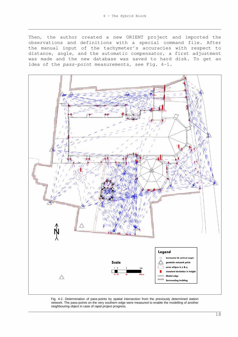
Then, the author created a new ORIENT project and imported the observations and definitions with a special command file. After the manual input of the tachymeter’s accuracies with respect to distance, angle, and the automatic compensator, a first adjustment was made and the new database was saved to hard disk. To get an idea of the pass-point measurements, see Fig. 4-1.
Fig. 4-1: Determination of pass-points by spatial intersection from the previously determined station network. The pass-points on the very southern edge were measured to enable the modelling of another neighbouring object in case of rapid project progress.
4 ~ The Hybrid Block
19
4.2 Photogrammetric Observations 4.2.1 Image Selection As all photogrammes had been stored in Canon-RAW format, a conversion to a format readable by ORPHEUS was necessary. The TIFF format would have complied with that, offering lossless compression, too. But as the project should stay portable on a widespread medium, which nowadays is the compact disc with a maximum normal capacity of 700MB, memory requirements had to be considered. Decompressed to the TIFF format, the taken photogrammes occupied 18MB each, whereas pictures converted to lowly compressed JPG format only required about 4MB of disk space. The author wanted to use up to a hundred images, so lowly compressed JPG was chosen. The following was a repetitive series of image import (see chapter 4.2.2), photo coordinate measurement of pass- and tie-points and a first image orientation (both cf. chapter 4.2.3), introduction of fictitious observations (chapter 4.3), hybrid block adjustment (chapter 4.5), modelling of the buildings (chapter 5.4), and replacement of images by other ones. This substitution was made in the case of newly introduced pictures minimising the number of images necessary to cover the whole model. On the one hand, this was done due to a geometric reason, the stability of the hybrid block: the fewer photogrammes used, the fewer orientations occur. On the other hand, this substitution was made because of a radiometric motive, concerning the texture export later on: every image is photographed with its own characteristics like brightness, contrast and colour saturation, which makes a photo model produced with different pictures look less natural with every untreated image added. However, the appropriate radiometric treatment is a lot of work, probably manual, and the amount of that work can be decreased by the reduction of the quantity of photos. Additionally, the selected images had to be free from hard shadows, as the correction of these errors claims a lot of work that cannot be automated. Of course, not only image replacement, but also the first selection of images was made under this point of view. Moreover, images to cover neighbouring sections on the façade should overlap to be able to measure and determine pass-, tie-, and face points, although this aspect did not have the same importance as usually in photogrammetry, because many pass-points all over the hybrid block had already been calculated. Nevertheless, every part of the model texture had to appear at least in one image, as a photogrammetric photo-model is a map of reality by definition, and texture must neither be duplicated, nor painted to achieve completeness.
4 ~ The Hybrid Block
20
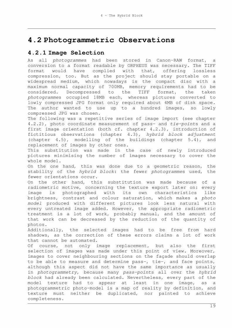
Besides, the image scale, i.e. the ratio of extents on the object and their mappings plays a big role. This ratio is a function of the distance between the object and the projection centre. Having in mind Nyquist’s sample theorem, at most half the size of the model resolution mr must be mapped on a pixel of the camera sensor. The following mathematical model assumes an ideal perspective projection, disregarding effects like aberration, etc. If a perspective’s object and image plane are parallel, the ratio of distances on the object to their mapped extents is constant all over the image. Therefore, the maximum distance dperp[m] for exposures with a sensor chip with square pixels and the optical axis perpendicular to the object plane can be calculated via the length of one pixel pxs[mm] with the simple formulas 4-1, using the camera’s interior orientation data (focal length f[mm], sensor chip resolution (count of pixels) sr[ ], sensor length sL[mm]) and the required model resolution mr[m] (cf. Fig. 4-2). In addition, the smallest angle ∆α in which half the model resolution must appear, can be determined.
(4-1)
The final photo model was planned to have a model resolution of 5cm on the church, and 2cm on the pavilion. Given the sensor chip extents of 22.7mm x 15.1mm, the sensor chip resolution of 3072px x 2048px, the adjusted resulting focal length of 15.619mm, the maximum distance for pictures taken perpendicular to the church resulted as about 50.7m, the one for the pavilion as 20.3m.
f
pxs2sL
atanf2sL
atan
2mr
pxsf
d
srsL
pxs
perp
−−=α∆
=
=
4 ~ The Hybrid Block
21
Fig. 4-2: Dependencies between the required model resolution (mr), the pixel size (pxs), the focal length (f) and the maximum distance (dperp) between the camera projection centre and an object plane perpendicular to the lens axis.
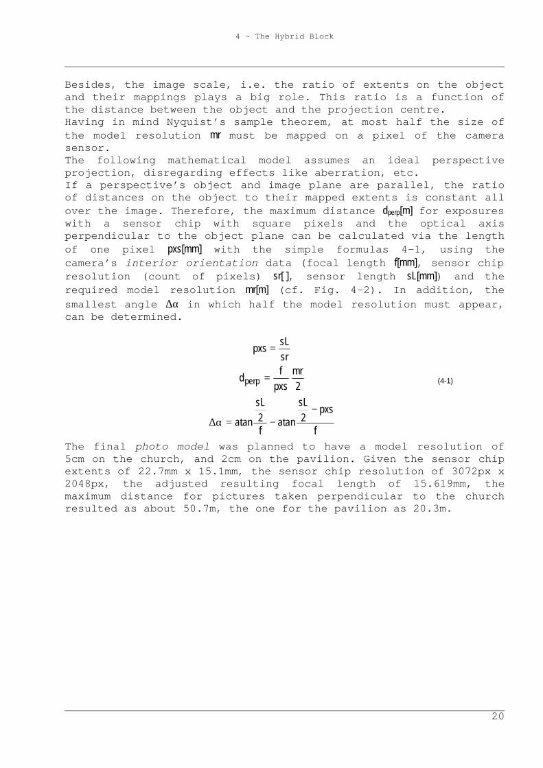
More sophisticated is the calculation of the maximum distance dmax between the projection centre and the object plane, if the angle γ between the lens axis and the normal of the object plane is different from zero. Subsequently, the ratio of the extent of a line segment on the object to its mapping is a function of its position, attitude and γ (cf. Fig. 4-3). To guarantee full model resolution overall the mapped object plane, one has to concentrate on the area on the object that is furthest from the projection centre, as a line segment there is mapped smallest, whatever direction it may have. Concerning the direction of a line segment in this area, the mapping is smallest, if the segment is parallel to the plane that is defined by the optical axis and the object plane normal (i.e. the plane of Fig. 4-3). Another line segment of same length and same position, but another attitude is mapped with larger extents, having a maximum if it is parallel to the sensor plane (i.e. perpendicular to the plane of the sketch shown below). Therefore, only line segments that lie in the planes of Fig. 4-3 and Fig. 4-4 must be borne in mind in the following considerations. The following calculus can be applied to any constellation of an object plane and a camera with a sensor chip with square pixels; there is not assumed a special camera attitude.
4 ~ The Hybrid Block
22
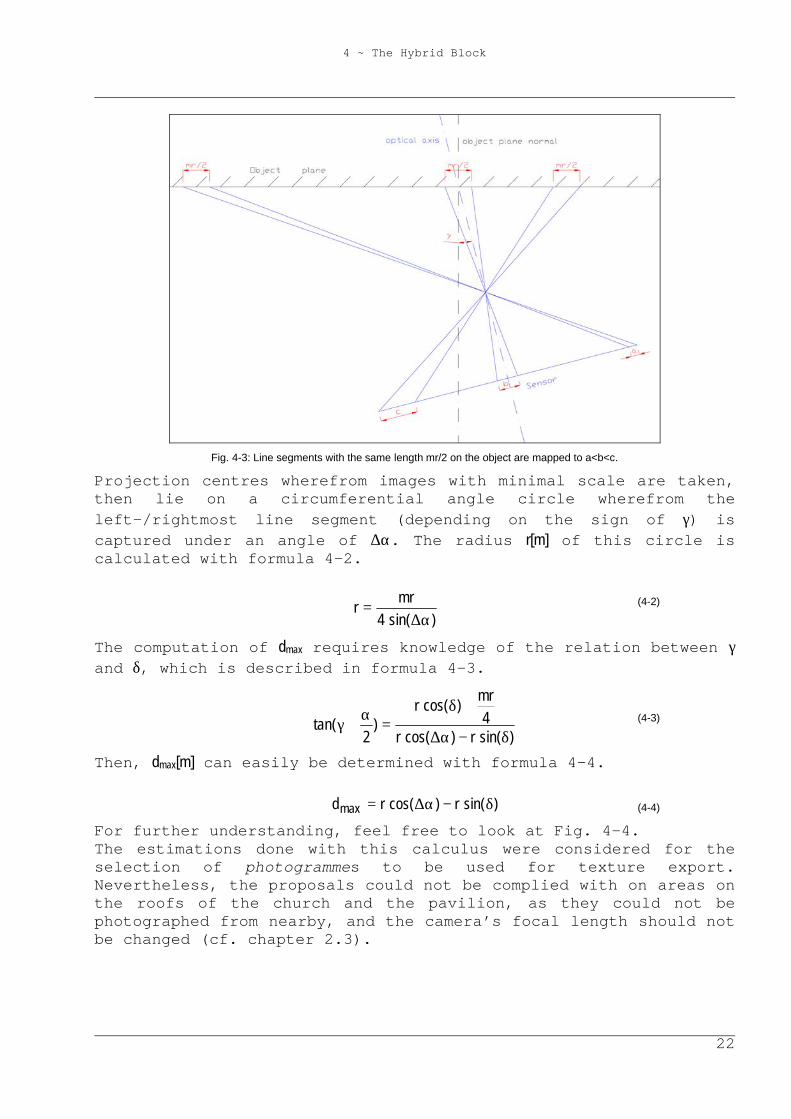
Fig. 4-3: Line segments with the same length mr/2 on the object are mapped to a<b<c.
Projection centres wherefrom images with minimal scale are taken, then lie on a circumferential angle circle wherefrom the left-/rightmost line segment (depending on the sign of γ) is captured under an angle of ∆α. The radius r[m] of this circle is calculated with formula 4-2.
(4-2)
The computation of dmax requires knowledge of the relation between γ and δ, which is described in formula 4-3.
(4-3)
Then, dmax[m] can easily be determined with formula 4-4.
(4-4)
For further understanding, feel free to look at Fig. 4-4. The estimations done with this calculus were considered for the selection of photogrammes to be used for texture export. Nevertheless, the proposals could not be complied with on areas on the roofs of the church and the pavilion, as they could not be photographed from nearby, and the camera’s focal length should not be changed (cf. chapter 2.3).
)sin(4mr
rα∆
=
)sin(r)cos(r4
mr)cos(r
)2
tan(δ−α∆
+δ=
α+γ
)sin(r)cos(rdmax δ−α∆=
4 ~ The Hybrid Block
23
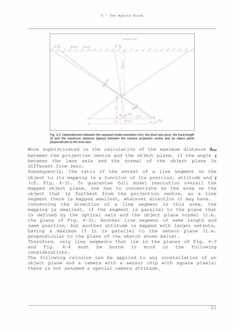
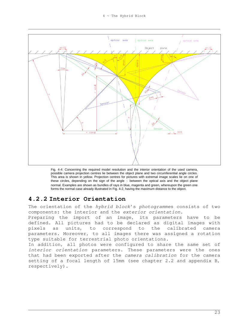
Fig. 4-4: Concerning the required model resolution and the interior orientation of the used camera, possible camera projection centres lie between the object plane and two circumferential angle circles. This area is shown in yellow. Projection centres for pictures with extremal image scales lie on one of these circles, depending on the sign of the angle g between the optical axis and the object plane normal. Examples are shown as bundles of rays in blue, magenta and green, whereupon the green one forms the normal case already illustrated in Fig. 4-2, having the maximum distance to the object.
4.2.2 Interior Orientation The orientation of the hybrid block’s photogrammes consists of two components: the interior and the exterior orientation. Preparing the import of an image, its parameters have to be defined. All pictures had to be declared as digital images with pixels as units, to correspond to the calibrated camera parameters. Moreover, to all images there was assigned a rotation type suitable for terrestrial photo orientations. In addition, all photos were configured to share the same set of interior orientation parameters. These parameters were the ones that had been exported after the camera calibration for the camera setting of a focal length of 15mm (see chapter 2.2 and appendix B, respectively).
4 ~ The Hybrid Block
24
ORPHEUS defines the image coordinate system of a digital photogramme by default as a right-handed Cartesian system, with its (x,y) plane in the image plane, where the x-axis points in row direction, and the y-axis against column direction, respectively. Its origin is located at the picture’s upper left corner. The transformation of the image coordinate system to the reference system refers to the photogramme’s projection centre. Knowledge of the image coordinate system is necessary to understand this transformation.
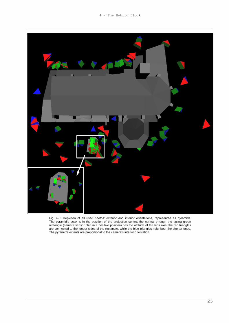
4.2.3 Exterior Orientation The rotation type of a photogramme has numerical importance only, as the calculation of a photo’s exterior orientation may fail or may be inaccurate, at least, depending on its attitude and rotation type. The type suitable for terrestrial photo orientations describes the rotation between two coordinate systems with the rotation angles α, ζ, and κ. Each angle defines a counterclockwise (mathematical positive) rotation around a coordinate axis, if seen from the peak of the axis towards the system’s origin. To transform the image coordinate system in a way, that its coordinate axes become parallel to the respective axes of the block’s reference system, rotations have to be done as follows: First, rotate around the z-axis by α, then rotate around the (already transformed) y-axis by ζ, finally, rotate around the (transformed) z-axis by κ. Transforming newly imported photos from the standard constellation to a first approximation of the final orientation was a simple thing, as in almost every picture there were at least four pass-points visible, which enabled the usage of the spatial resection named after Müller and Killian. Have a glance at Fig. 4-5 showing a map of the used photos’ exterior and interior orientations. This image can be seen enlarged at the end of this document. As all photos displayed overlapping areas on the façade, tie-points for better block stability could be measured in zones with adequate texture. Whenever possible, these tie-points were positioned on corners of the objects, serving as vertices of the photorealistic model.
4 ~ The Hybrid Block
25
Fig. 4-5: Depiction of all used photos’ exterior and interior orientations, represented as pyramids. The pyramid’s peak is in the position of the projection centre; the normal through the facing green rectangle (camera sensor chip in a positive position) has the attitude of the lens axis; the red triangles are connected to the longer sides of the rectangle, while the blue triangles neighbour the shorter ones. The pyramid’s extents are proportional to the camera’s interior orientation.
4 ~ The Hybrid Block
26
4.3 Gestalt Observations Orientalists are used to employ fictitious observations like ‘Gestalts’. Zero-distances between points and some kind of shape are ‘observed’ with certain accuracy and are minimized in the following hybrid block adjustment. Depending on the subtype of the Gestalt, explicit and implicit equations can be used to describe its shape. For explicit functions, the discrepancy in the respective coordinate direction (x, y, or z) is minimized; this is adequate for shapes that can be expressed in 2.5 dimensions, like planes, street surfaces, roofs, and alike. In other cases, implicit Gestalts must be used. These provide two types of residual treatment: either, the algebraïcal residual is minimized i.e., the shape’s gradient is used to ‘metrify’ the discrepancy, or the length of the residual orthogonal to the shape is minimized. For further information, cf. [Kager, 2000, p. 472-479]. The same exterior orientation and defining functions of a Gestalt can be used for several rooms. In addition, the local coordinate system can be mirrored to express symmetries (cf. chapter 4.3.1 and [Rottensteiner, 2001, p. 257-264]). In this project, explicit Gestalts were used extensively, above all for economical reasons [Dorffner, 2002, p. 14]. That is, once a Gestalt is determined, the computation of an object point on it requires one observation less with every Gestalt equation. For example, if a point is part of a plane, the two image coordinates in one photogramme are sufficient to determine its position in space. Moreover, explicit Gestalts had to be defined, because several areas on the objects only appeared in one image and could not be photographed from another position. Thus, the use of Gestalts not only made the project advance faster, but it enabled the creation of the model. Obviously, the buildings’ façades consist of two sets of vertical planes that are perpendicular to each other (cf. Fig. 4-5). Furthermore, many vertices have the same height. To ease the corresponding Gestalt definitions, these planes ought to be defined parallel to the (X,Y), (X,Z) and (Y,Z) plane of the object coordinate system, which required a re-definition of the object coordinate system based on the object geometry. Therefore, the system definition was changed from four tachymeter station coordinates to four object point coordinates (cf. chapter 4.1). The two corresponding points lie in the largest member of the set of planes of the church’s façade mentioned above. The two defining points are in a large distance from each other, for a more precise system definition.
4 ~ The Hybrid Block
27
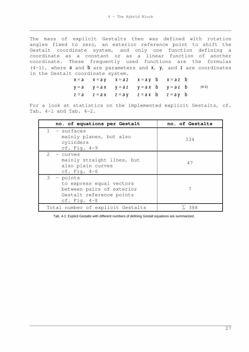
The mass of explicit Gestalts then was defined with rotation angles fixed to zero, an exterior reference point to shift the Gestalt coordinate system, and only one function defining a coordinate as a constant or as a linear function of another coordinate. These frequently used functions are the formulas (4-1), where a and b are parameters and x, y, and z are coordinates in the Gestalt coordinate system.
(4-1)
For a look at statistics on the implemented explicit Gestalts, cf. Tab. 4-1 and Tab. 4-2.
no. of equations per Gestalt no. of Gestalts 1 – surfaces
mainly planes, but also cylinders cf. Fig. 4-9
334
2 – curves mainly straight lines, but also plain curves cf. Fig. 4-6
47
3 - points to express equal vectors between pairs of exterior Gestalt reference points cf. Fig. 4-8
7
Total number of explicit Gestalts S 388 Tab. 4-1: Explicit Gestalts with different numbers of defining Gestalt equations are summarized.
byazbxazyazxazazbzaybxayzayxayaybzaxbyaxzaxyaxax
+=+====+=+====+=+====
4 ~ The Hybrid Block
28
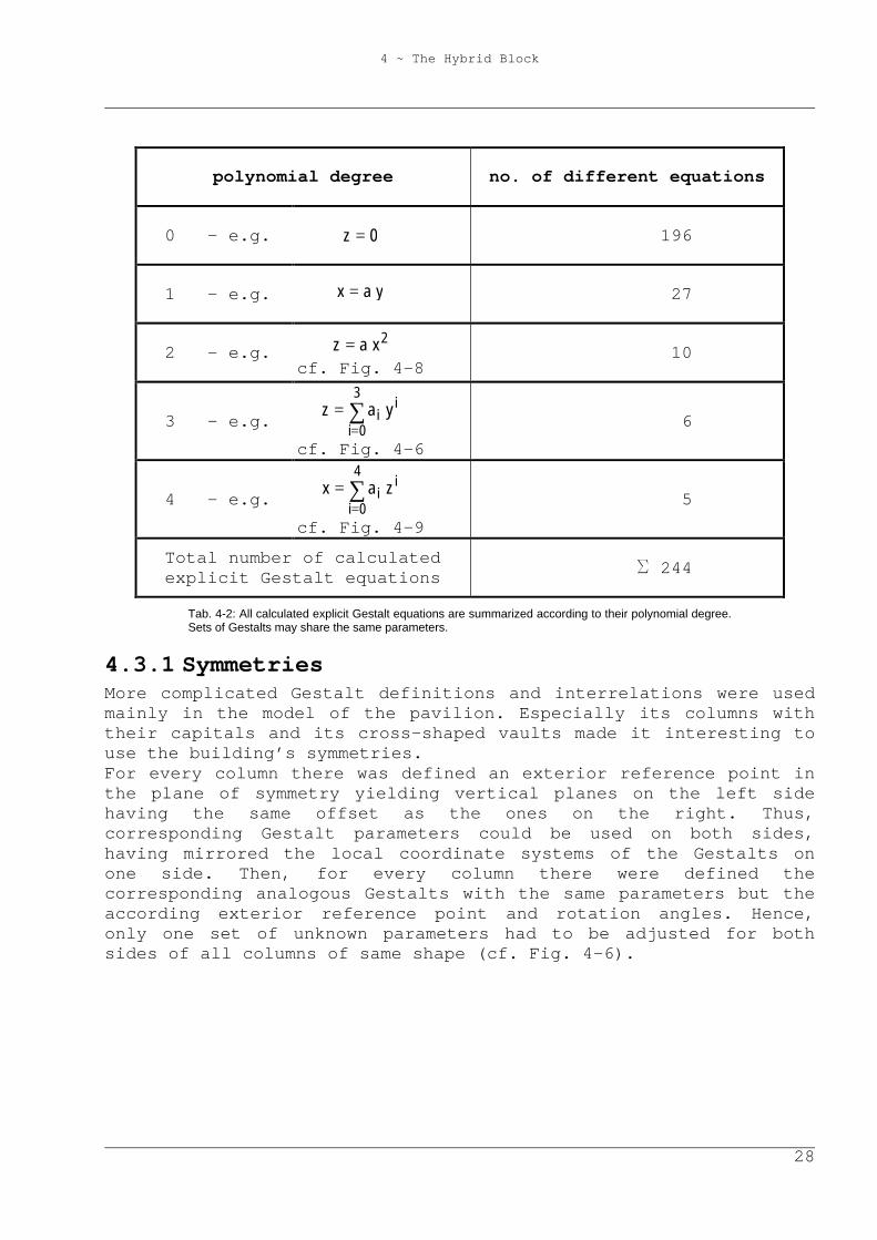
polynomial degree no. of different equations
0 – e.g. 0z = 196
1 – e.g. yax = 27
2 – e.g. 2xaz =
cf. Fig. 4-8 10
3 – e.g. ∑=
=3
0i
ii yaz
cf. Fig. 4-6 6
4 – e.g. ∑=
=4
0i
ii zax
cf. Fig. 4-9 5
Total number of calculated explicit Gestalt equations S 244
Tab. 4-2: All calculated explicit Gestalt equations are summarized according to their polynomial degree. Sets of Gestalts may share the same parameters.
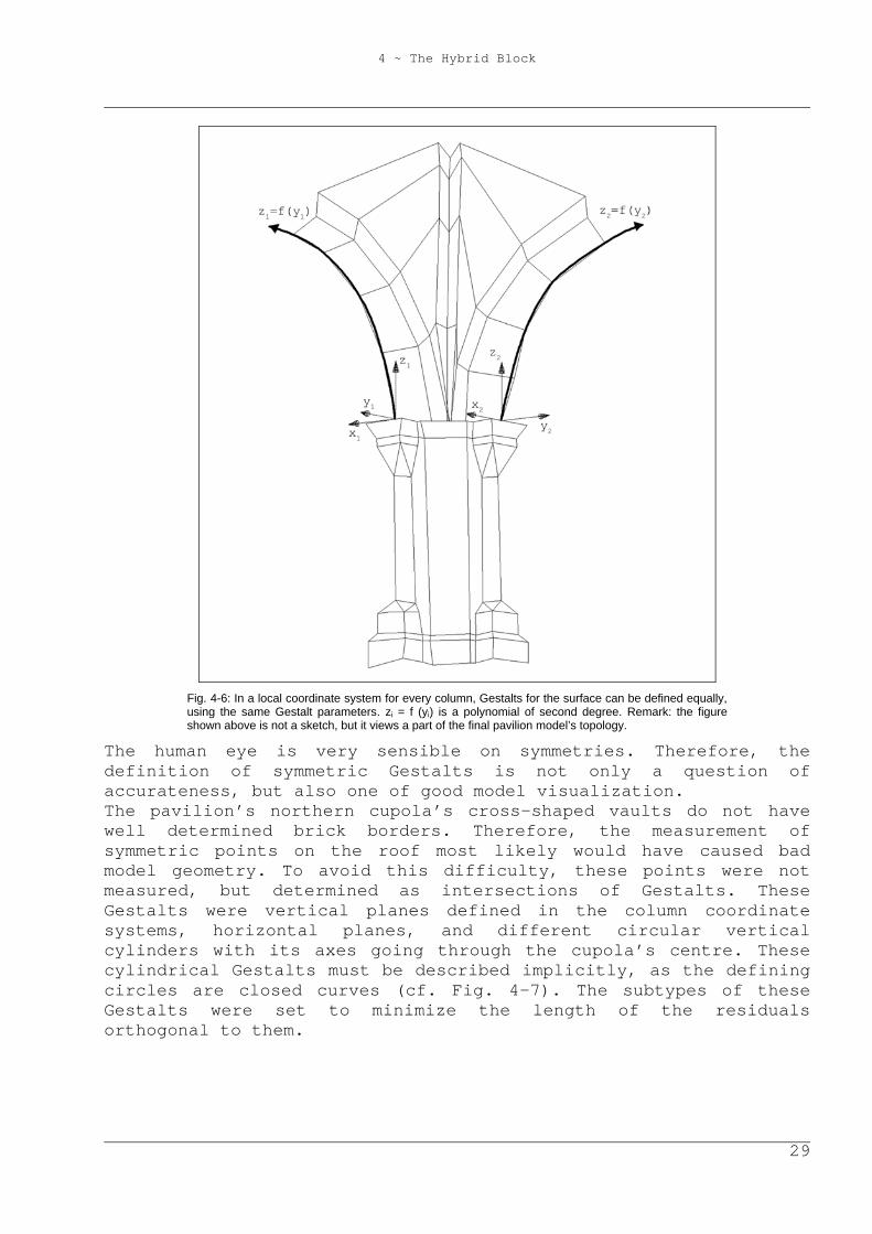
4.3.1 Symmetries More complicated Gestalt definitions and interrelations were used mainly in the model of the pavilion. Especially its columns with their capitals and its cross-shaped vaults made it interesting to use the building’s symmetries. For every column there was defined an exterior reference point in the plane of symmetry yielding vertical planes on the left side having the same offset as the ones on the right. Thus, corresponding Gestalt parameters could be used on both sides, having mirrored the local coordinate systems of the Gestalts on one side. Then, for every column there were defined the corresponding analogous Gestalts with the same parameters but the according exterior reference point and rotation angles. Hence, only one set of unknown parameters had to be adjusted for both sides of all columns of same shape (cf. Fig. 4-6).
4 ~ The Hybrid Block
29
Fig. 4-6: In a local coordinate system for every column, Gestalts for the surface can be defined equally, using the same Gestalt parameters. zi = f (yi) is a polynomial of second degree. Remark: the figure shown above is not a sketch, but it views a part of the final pavilion model’s topology.
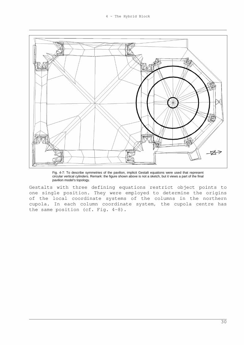
The human eye is very sensible on symmetries. Therefore, the definition of symmetric Gestalts is not only a question of accurateness, but also one of good model visualization. The pavilion’s northern cupola’s cross-shaped vaults do not have well determined brick borders. Therefore, the measurement of symmetric points on the roof most likely would have caused bad model geometry. To avoid this difficulty, these points were not measured, but determined as intersections of Gestalts. These Gestalts were vertical planes defined in the column coordinate systems, horizontal planes, and different circular vertical cylinders with its axes going through the cupola’s centre. These cylindrical Gestalts must be described implicitly, as the defining circles are closed curves (cf. Fig. 4-7). The subtypes of these Gestalts were set to minimize the length of the residuals orthogonal to them.
4 ~ The Hybrid Block
30
Fig. 4-7: To describe symmetries of the pavilion, implicit Gestalt equations were used that represent circular vertical cylinders. Remark: the figure shown above is not a sketch, but it views a part of the final pavilion model’s topology.
Gestalts with three defining equations restrict object points to one single position. They were employed to determine the origins of the local coordinate systems of the columns in the northern cupola. In each column coordinate system, the cupola centre has the same position (cf. Fig. 4-8).
4 ~ The Hybrid Block
31
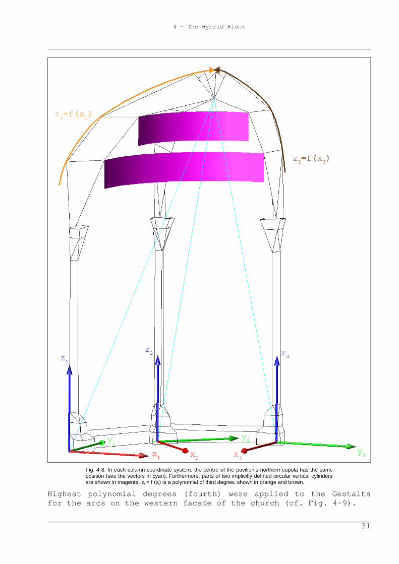
Fig. 4-8: In each column coordinate system, the centre of the pavilion’s northern cupola has the same position (see the vectors in cyan). Furthermore, parts of two implicitly defined circular vertical cylinders are shown in magenta. zi = f (xi) is a polynomial of third degree, shown in orange and brown.
Highest polynomial degrees (fourth) were applied to the Gestalts for the arcs on the western facade of the church (cf. Fig. 4-9).
4 ~ The Hybrid Block
32
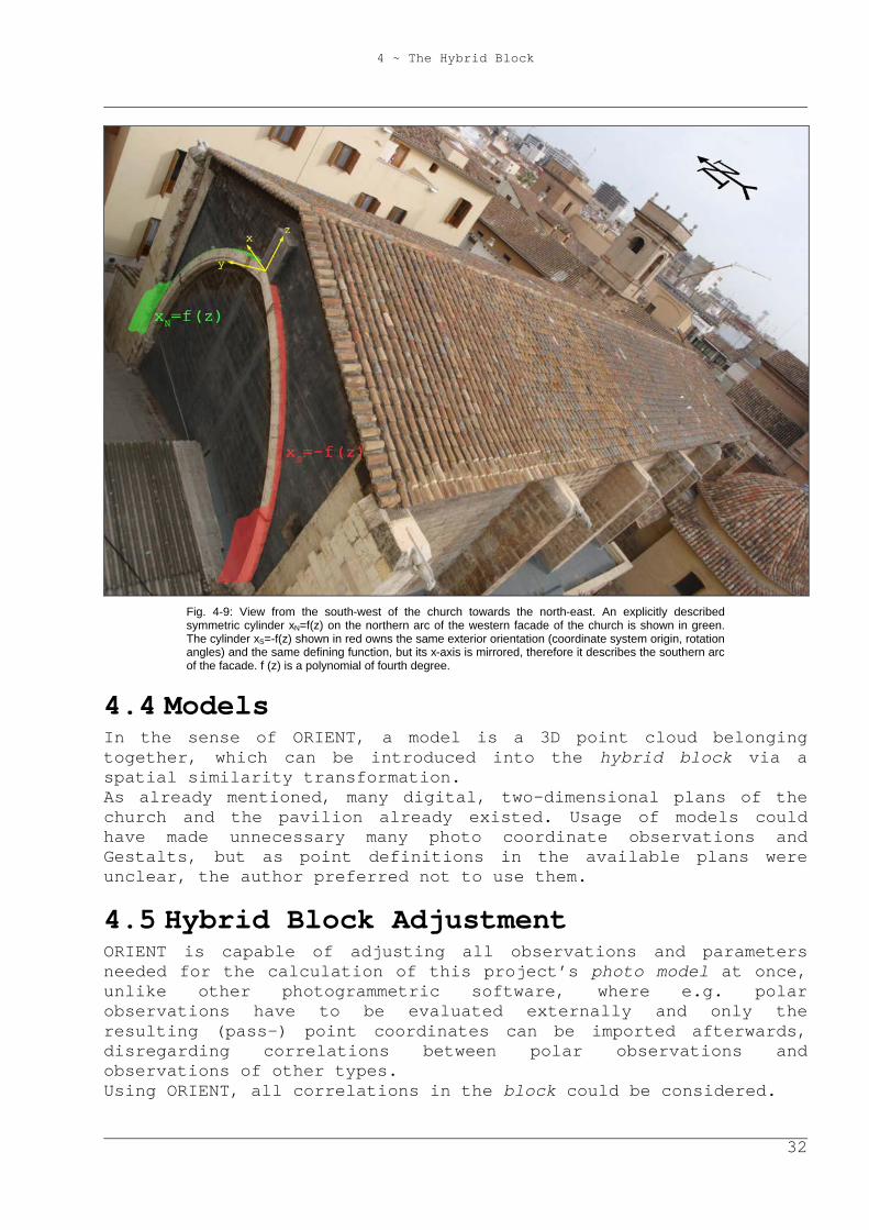
Fig. 4-9: View from the south-west of the church towards the north-east. An explicitly described symmetric cylinder xN=f(z) on the northern arc of the western facade of the church is shown in green. The cylinder xS=-f(z) shown in red owns the same exterior orientation (coordinate system origin, rotation angles) and the same defining function, but its x-axis is mirrored, therefore it describes the southern arc of the facade. f (z) is a polynomial of fourth degree.
4.4 Models In the sense of ORIENT, a model is a 3D point cloud belonging together, which can be introduced into the hybrid block via a spatial similarity transformation. As already mentioned, many digital, two-dimensional plans of the church and the pavilion already existed. Usage of models could have made unnecessary many photo coordinate observations and Gestalts, but as point definitions in the available plans were unclear, the author preferred not to use them.
4.5 Hybrid Block Adjustment ORIENT is capable of adjusting all observations and parameters needed for the calculation of this project’s photo model at once, unlike other photogrammetric software, where e.g. polar observations have to be evaluated externally and only the resulting (pass-) point coordinates can be imported afterwards, disregarding correlations between polar observations and observations of other types. Using ORIENT, all correlations in the block could be considered.
4 ~ The Hybrid Block
33
Moreover, the operator can select subsets of observations and parameters to be adjusted. This can be quite useful to get first approximations of new parameters while already determined ones stay in range and observations that do not affect much the new parameters do not prolong calculation time needlessly. Furthermore, gross errors can be detected with robust estimation and their observations may be deactivated. In addition, the adjustment’s functional and stochastic model can be inspected in the adjustment protocol, where tests on significance, correlations, normalized and maximum discrepancies, inner reliabilities, global deformations, variance components analyses, and even more appear. The whole spectrum of adjustment analysis was employed, which facilitated the correct calculation and a fast project advance. Finally, the following observation types occurred in the hybrid block:
- image: x-, y-coordinates. - polar: horizontal angles, vertical angles, and distances. - Gestalt: zero-distances between a point and some kind of
shape; these assumptions are described by equations for the x-, y-, or z-coordinate (cf. Tab. 4-1).
- theodolite levelling (observed parameters): ω, φ (rotation angles around the x- and y-axis; for explanations of the respective transformation, look for the rotation with ω, φ, κ in chapter 6.5.1).
- Gestalt attitude (observed parameters): ω, φ (rotation angles around the x- and y-axis).
For every observation, its standard deviation had to be set. Partly, this was a quite difficult task, because basically, the variance of an observation is the sum of the variance of the measuring instrument and the variance of the definition of the object that is measured. Thus, image, polar, and Gestalt observation accuracies depend on the quality of the object points’ definition. However, these points were defined very differently well, ranging from a few millimetres to several centimetres. Therefore, it would have been statistically correct to estimate a standard deviation for each observation. However, this is a bad idea, for economical reasons. These estimations would have delayed work too much. Therefore, in general, the same standard deviation was given to observations of the same type. Some observation types were subdivided into several precision classes with different standard deviations: well/badly observable image coordinates and four classes of Gestalts.
4 ~ The Hybrid Block
34
4.5.1 Functional Model Finalization Having defined the stochastic model with estimated standard deviations, the next step was to enhance the functional model. Above all, the definition of curved Gestalts was arguable. There was not an architect’s plan available to the author, and it is impossible to determine with the naked eye the exact degree of the polynomial that shall represent a curved part of the object facade. Therefore, Gestalt parameters had to be tested on significance and correlation. According to that, degrees of the polynomials were accepted or omitted, just like during the camera calibration in chapter 2.2. After that, some gross errors were detected with robust estimation and the respective observations were corrected. In the case of discrepancies being related to Gestalt observations, it was checked, if an alteration of the respective accuracies with plausible values seemed advisable. Still, some observations had larger discrepancies although the block did not contain errors any more. The absence of gross errors was proven by the histogram of a priori normalized discrepancies, which indicated an approximate normal distribution. Among others, explanations for the remaining discrepancies could be:
- Image observations: in chapter 2.3, the author discovered that the used camera’s interior orientation was unstable during the data capture for the camera calibration, even though the image data was captured during one hour only. The photogrammes used to calculate the photo model were taken during several days in March and May. Therefore, even less stability could be assumed.
4 ~ The Hybrid Block
35
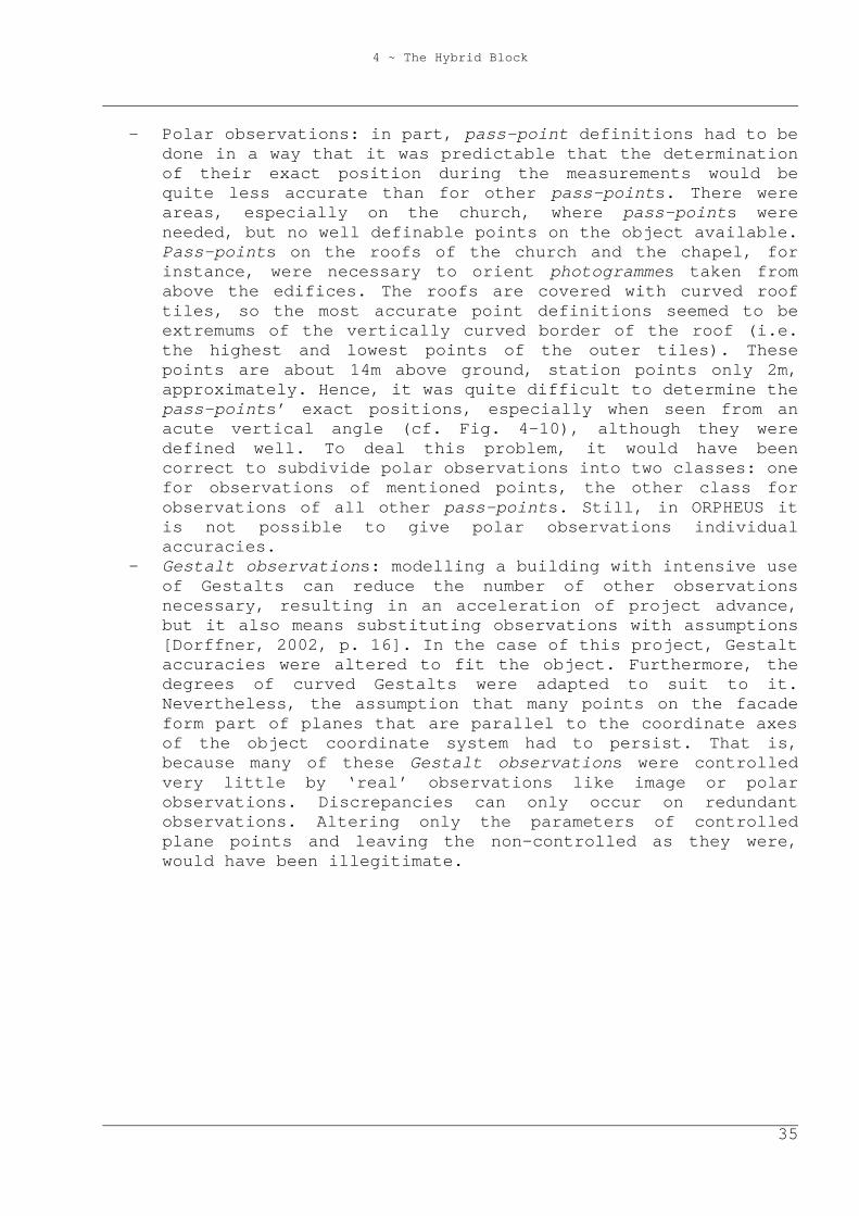
- Polar observations: in part, pass-point definitions had to be done in a way that it was predictable that the determination of their exact position during the measurements would be quite less accurate than for other pass-points. There were areas, especially on the church, where pass-points were needed, but no well definable points on the object available. Pass-points on the roofs of the church and the chapel, for instance, were necessary to orient photogrammes taken from above the edifices. The roofs are covered with curved roof tiles, so the most accurate point definitions seemed to be extremums of the vertically curved border of the roof (i.e. the highest and lowest points of the outer tiles). These points are about 14m above ground, station points only 2m, approximately. Hence, it was quite difficult to determine the pass-points’ exact positions, especially when seen from an acute vertical angle (cf. Fig. 4-10), although they were defined well. To deal this problem, it would have been correct to subdivide polar observations into two classes: one for observations of mentioned points, the other class for observations of all other pass-points. Still, in ORPHEUS it is not possible to give polar observations individual accuracies.
- Gestalt observations: modelling a building with intensive use of Gestalts can reduce the number of other observations necessary, resulting in an acceleration of project advance, but it also means substituting observations with assumptions [Dorffner, 2002, p. 16]. In the case of this project, Gestalt accuracies were altered to fit the object. Furthermore, the degrees of curved Gestalts were adapted to suit to it. Nevertheless, the assumption that many points on the facade form part of planes that are parallel to the coordinate axes of the object coordinate system had to persist. That is, because many of these Gestalt observations were controlled very little by ‘real’ observations like image or polar observations. Discrepancies can only occur on redundant observations. Altering only the parameters of controlled plane points and leaving the non-controlled as they were, would have been illegitimate.
4 ~ The Hybrid Block
36
Fig. 4-10: Pass-points on the roofs of the chapel and the church are needed to orient photogrammes taken from above the objects. They are defined best as highest outer points of roof tiles. Still, their image coordinate and polar observations are not supposed to be as accurate as most other pass-points, especially when seen from an acute vertical angle. The same pass-point is seen from three different points of view: twice from a geodetic station (left, middle), once in a photogramme (right).
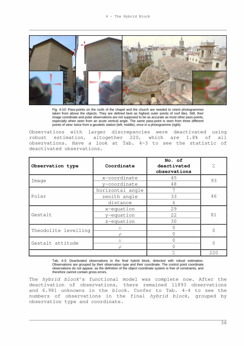
Observations with larger discrepancies were deactivated using robust estimation, altogether 220, which are 1.8% of all observations. Have a look at Tab. 4-3 to see the statistic of deactivated observations.
Observation type Coordinate No. of
deactivated observations
S
x-coordinate 45 Image y-coordinate 48
93
horizontal angle 7 zenith angle 33 Polar
distance 6 46
x-equation 29 y-equation 22 Gestalt z-equation 30
81
w 0 Theodolite levelling f 0
0
w 0 Gestalt attitude f 0
0
S 220 Tab. 4-3: Deactivated observations in the final hybrid block, detected with robust estimation. Observations are grouped by their observation type and their coordinate. The control point coordinate observations do not appear, as the definition of the object coordinate system is free of constraints, and therefore cannot contain gross errors.
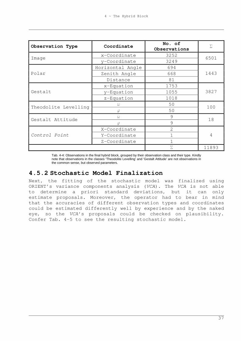
The hybrid block’s functional model was complete now. After the deactivation of observations, there remained 11893 observations and 6.981 unknowns in the block. Confer to Tab. 4-4 to see the numbers of observations in the final hybrid block, grouped by observation type and coordinate.
4 ~ The Hybrid Block
37
Observation Type Coordinate No. of Observations S
x-Coordinate 3252 Image y-Coordinate 3249
6501
Horizontal Angle 694 Zenith Angle 668 Polar
Distance 81 1443
x-Equation 1753 y-Equation 1055 Gestalt z-Equation 1018
3827
w 50 Theodolite Levelling f 50
100
w 9 Gestalt Attitude f 9
18
X-Coordinate 2 Y-Coordinate 1 Control Point Z-Coordinate 1
4
S 11893 Tab. 4-4: Observations in the final hybrid block, grouped by their observation class and their type. Kindly note that observations in the classes ‘Theodolite Levelling’ and ‘Gestalt Attitude’ are not observations in the common sense, but observed parameters.
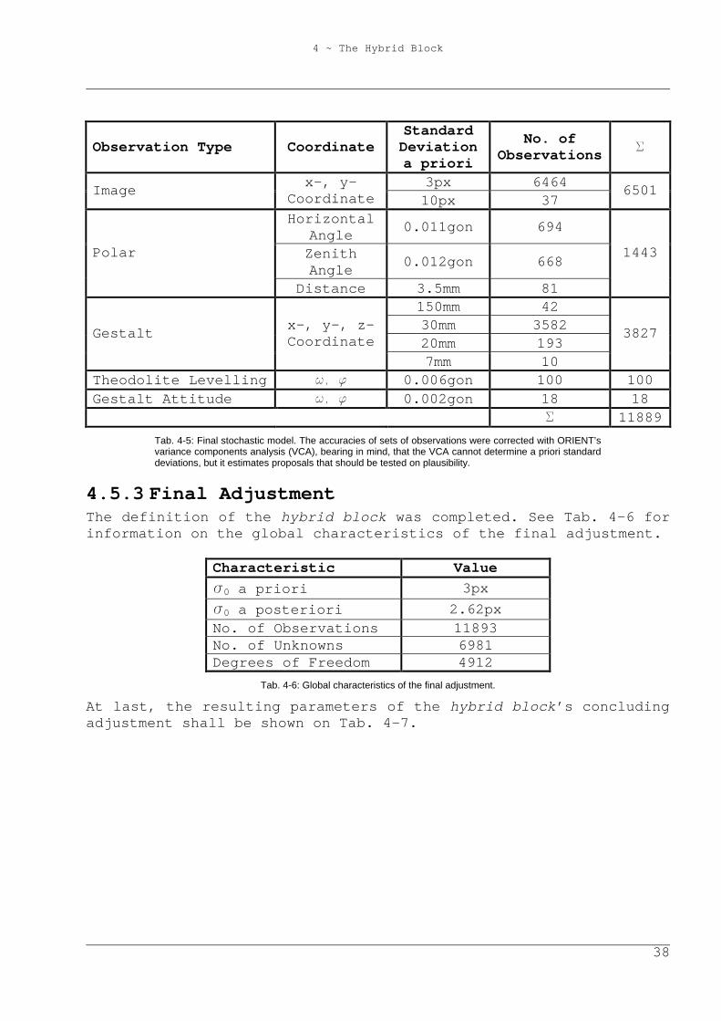
4.5.2 Stochastic Model Finalization Next, the fitting of the stochastic model was finalized using ORIENT’s variance components analysis (VCA). The VCA is not able to determine a priori standard deviations, but it can only estimate proposals. Moreover, the operator had to bear in mind that the accuracies of different observation types and coordinates could be estimated differently well by experience and by the naked eye, so the VCA’s proposals could be checked on plausibility. Confer Tab. 4-5 to see the resulting stochastic model.
4 ~ The Hybrid Block
38
Observation Type Coordinate Standard Deviation a priori
No. of Observations S
3px 6464 Image x-, y-Coordinate 10px 37
6501
Horizontal Angle 0.011gon 694
Zenith Angle 0.012gon 668 Polar
Distance 3.5mm 81
1443
150mm 42 30mm 3582 20mm 193
Gestalt x-, y-, z- Coordinate
7mm 10
3827
Theodolite Levelling w, f 0.006gon 100 100 Gestalt Attitude w, f 0.002gon 18 18 S 11889
Tab. 4-5: Final stochastic model. The accuracies of sets of observations were corrected with ORIENT’s variance components analysis (VCA), bearing in mind, that the VCA cannot determine a priori standard deviations, but it estimates proposals that should be tested on plausibility.
4.5.3 Final Adjustment The definition of the hybrid block was completed. See Tab. 4-6 for information on the global characteristics of the final adjustment.
Characteristic Value s0 a priori 3px s0 a posteriori 2.62px No. of Observations 11893 No. of Unknowns 6981 Degrees of Freedom 4912
Tab. 4-6: Global characteristics of the final adjustment.
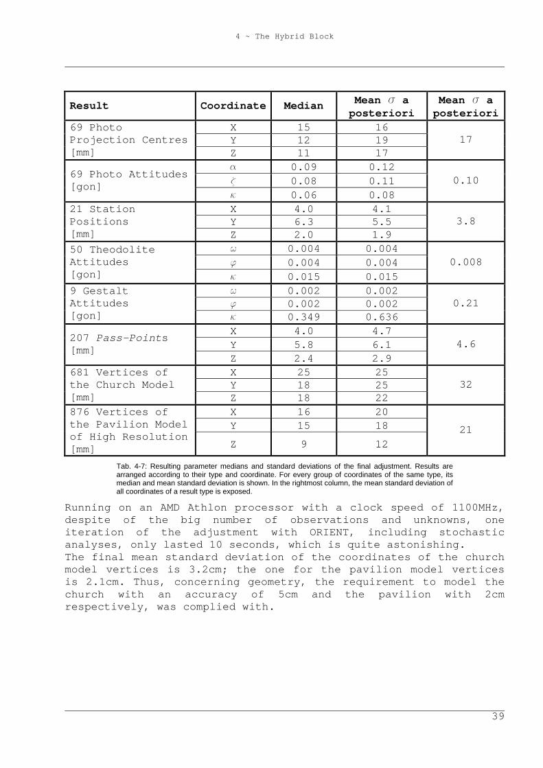
At last, the resulting parameters of the hybrid block’s concluding adjustment shall be shown on Tab. 4-7.
4 ~ The Hybrid Block
39
Result Coordinate Median Mean s a posteriori
Mean s a posteriori
X 15 16 Y 12 19
69 Photo Projection Centres [mm] Z 11 17
17
a 0.09 0.12 z 0.08 0.11 69 Photo Attitudes
[gon] k 0.06 0.08
0.10
X 4.0 4.1 Y 6.3 5.5
21 Station Positions [mm] Z 2.0 1.9
3.8
w 0.004 0.004 f 0.004 0.004
50 Theodolite Attitudes [gon] k 0.015 0.015
0.008
w 0.002 0.002 f 0.002 0.002
9 Gestalt Attitudes [gon] k 0.349 0.636
0.21
X 4.0 4.7 Y 5.8 6.1 207 Pass-Points
[mm] Z 2.4 2.9
4.6
X 25 25 Y 18 25
681 Vertices of the Church Model [mm] Z 18 22
32
X 16 20 Y 15 18
876 Vertices of the Pavilion Model of High Resolution [mm] Z 9 12
21
Tab. 4-7: Resulting parameter medians and standard deviations of the final adjustment. Results are arranged according to their type and coordinate. For every group of coordinates of the same type, its median and mean standard deviation is shown. In the rightmost column, the mean standard deviation of all coordinates of a result type is exposed.
Running on an AMD Athlon processor with a clock speed of 1100MHz, despite of the big number of observations and unknowns, one iteration of the adjustment with ORIENT, including stochastic analyses, only lasted 10 seconds, which is quite astonishing. The final mean standard deviation of the coordinates of the church model vertices is 3.2cm; the one for the pavilion model vertices is 2.1cm. Thus, concerning geometry, the requirement to model the church with an accuracy of 5cm and the pavilion with 2cm respectively, was complied with.
5 ~ Modelling
40
5 Modelling Having computed the model’s vertices, there was left to do the definition of its topology.
5.1 VRML97 VRML97 or VRML 2.0 is a data format for the definition of spatial objects, which is defined by the Web3D Consortium [VRML97, 1997]. It is an advancement of VRML 1.0, differing mainly in the ability to make objects dynamic. It can be viewed in internet browsers using a small plug-in. Therefore, it is capable of reaching a widespread public. Almost any imaginable kind of spatial object can be described, like points, curves, surfaces, bodies. Its appearance can be controlled by colours, colour functions, image textures, lights, reflection properties, opacity, and much more. The user views the virtual world perspectively like a camera (called AVATAR), with a certain viewing angle and the image size depending on the resolution of the browser window. Hence, he or she can get a very realistic image of the model.
5.2 ORPHEUS Model Restrictions ORPHEUS is able to export a model in the VRML97 format, but it stores the data in a different way. Point coordinates form part of the ORIENT database, wherefrom the model’s vertex coordinates and vector elements are updated or calculated, respectively. The model’s topology is recorded in boundary representation (B-rep), which is the format implemented in the VRaniML© library1 that is used by ORPHEUS for object modelling. Defining a spatial model in boundary representation means defining the outer loops of its faces (i.e., their boundary polygons). These polygons, their edges, and vertices must fulfil the following requirements [Kager et al., 2002, p. 160]:
1 http://www.greathill.com
5 ~ Modelling
41
- polygons are planar (up to a certain threshold). - each object edge connects exactly two vertices. - each edge has one or two neighbouring faces (loops). This
means that the boundary model must not touch itself in an edge. Within two loops, the edge is contained in opposite orientations.
- every vertex is surrounded by a single cycle of edges and faces, i.e., the boundary model must not touch itself in a vertex.
- it is not possible to create faces having holes, i.e., inner loops. This can be circumvented by cutting faces with holes into two or more parts.
Furthermore, each model face must be defined completely in a single photogramme. For texture export, the face’s adjusted image points must be inside this picture.
5.3 Web Requirements The photo model is intended to be provided on the internet. This implies that different transfer rates, computers, and software have to be taken into mind. Transmission time is straight proportional to the amount of data to be transferred. Therefore, various texture resolutions and diverse geometric details should be offered in different versions of the model, to consider different speeds of internet connections. In addition to the texture resolution and the geometric detail, above all, dynamics in the model demand great performance from the computer. Thus, versions without much interactivity and calculations should be made available. Concerning the software installed on computers viewing the model, above all, different internet browsers and VRML-plug-ins must be considered, as they use to interpret html- and VRML-code slightly different.
5.4 Modelling San Juan The final model consists of two parts, as the required model resolution of the church is different from the one of the pavilion and ORPHEUS can only export a model with the same resolution for all its components. The two resulting VRML97-files are then included (‘inlayed’) into a single file. The model of the church contains the whole façade. Areas, where external buildings contact the church or that could not be photographed, are coloured grey. Moreover, the lower, open boundary of the façade is closed with grey faces.
5 ~ Modelling
42
The church is delimited by an external building in the West, and the interior of the church was not modelled. As the animated view (cf. chapter 6.2) was planned to go along a circular route on the ground, it had to cross the inside. Thus, a corridor between the north-eastern and the southern entrance was invented. That is, because common VRML-plug-ins treat faces viewed from behind like non-existent, and the user would see the outside of the church from its inside, which would be quite irritating. The model of the church contains 681 vertices, 1205 edges, and 510 faces. The pavilion is modelled similarly, but in addition, the model contains the inside, too. The model’s geometric detail is higher, just like its texture resolution. To decrease its affect on the viewing computer’s performance, it should be viewed in highest quality only if seen from nearby. Thus, an additional model was created that describes just the exterior of the building in a simplified way. The pavilion model of high resolution contains 876 vertices, 1705 edges and 825 faces, the one of low quality 15 vertices, 24 edges, and 10 faces, correspondingly.
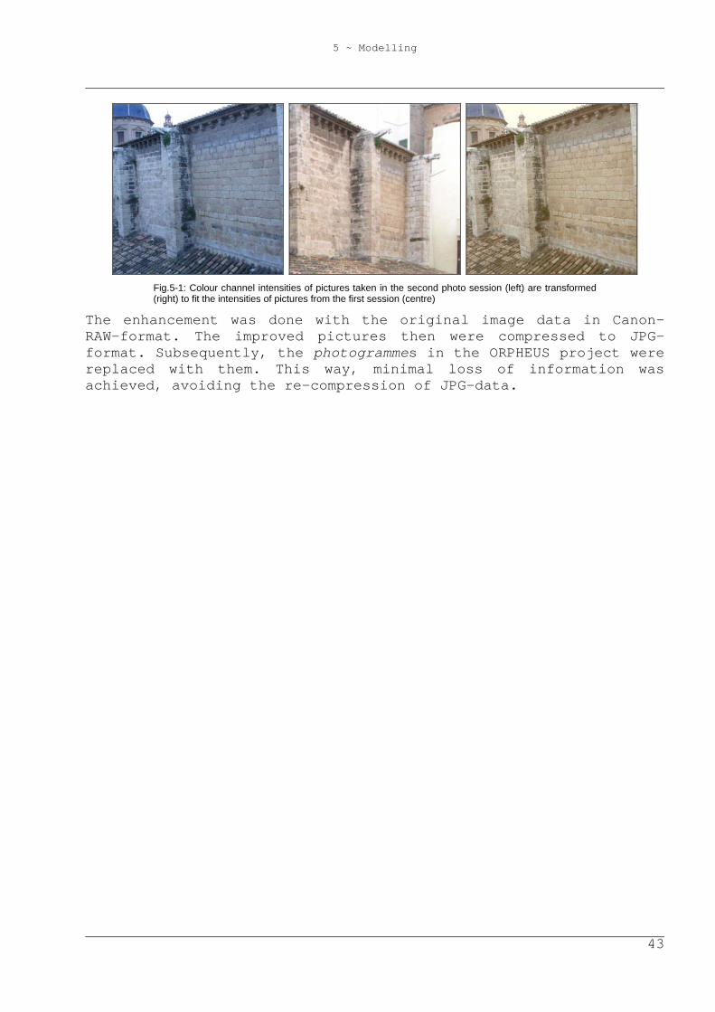
5.5 Image Enhancement Once the model was created, radiometric differences on textures representing the same surface types attracted attention. Apart from shadows, there are many reasons for this. The appearance of a surface also depends on the position of the sun or other lights, its light spectrum, the point of view, the diffuseness of the atmosphere, the reflection properties of the surface, and the form of the surface, which can produce tiny shadows itself. Thus, adjusting the appearance of a surface type all over the object (e.g. the redbrick roofs) can hardly be automated and is a lot of work when made manually. As there was not a program at the author’s disposal to do this, only a coarse radiometric adjustment was made. That is, the different weather during the second photo session in May was considered. That day it was a bit foggier. Therefore, the atmosphere reflected more blue light, and the taken photos’ blue channels resulted more intensive than during the first session. Middle adjustment values for the three colour channels were determined manually by comparisons of photos from different sessions showing the same surfaces. These values were added to / subtracted from the according channels of all photos made in May (see Fig.5-1).
5 ~ Modelling
43
Fig.5-1: Colour channel intensities of pictures taken in the second photo session (left) are transformed (right) to fit the intensities of pictures from the first session (centre)
The enhancement was done with the original image data in Canon-RAW-format. The improved pictures then were compressed to JPG-format. Subsequently, the photogrammes in the ORPHEUS project were replaced with them. This way, minimal loss of information was achieved, avoiding the re-compression of JPG-data.
6 ~ VRML Programming
44
6 VRML Programming The following properties and dynamic elements of the produced VRML world cannot be specified or created in ORPHEUS. The programming was done in VRML97, including Javascript scripts. The files exported from ORPHEUS should only be included and not be changed during programming, to be able to update the shown VRML-world with a new ORPHEUS export of the (enhanced) model without complications even after the programming work would be finished.
6.1 Level of Detail VRML97 offers a switch between different models according to the distance between the AVATAR and a cube. This feature is called ‘Level of detail’ (LOD). As mentioned above, the pavilion model of high quality owns a big number of vertices, edges, faces, and high-resolution textures. Therefore, it occupies much working memory, and it demands high performance from the CPU and the graphics card. As a result, jerking views can result during navigation. Thus, the LOD-switch was installed in a way that the pavilion model of high resolution appears only if the virtual viewer is nearby the pavilion. Otherwise, the simple model is shown.
6.2 Animating the Point of View The user can navigate interactively through VRML-worlds, but his or her point of view can also be directed by the world itself. Interactive navigation requires some experience. Therefore, it is advisable to provide programmed guidance to the user at least in narrow places, where navigation must be made even more accurately. Furthermore, this is a good alternative to view rapidly the world’s nicest things. The AVATAR’s positions and attitudes are then interpolated linearly between key values; the interpolation speed can be set freely.
6 ~ VRML Programming
45
In the case of this project, the animation can be started from a point of view that shows an orthophoto of Valencia’s historical centre from above (cf. chapter 6.6.1), with a text overlaid that gives some short information about the project, the creator of the world, his primary mentors and the used photogrammetric software. After the start, the AVATAR’s viewing angle is magnified due to the narrow situation along the route.
6.3 Non-Geometric Information In addition to the overlaid text at the start of the animation, non-geometric information is provided at three points all over the site, where it seemed of great importance to the author. At these points, the user can switch into view briefings about the Romanesque portal from the 13th century, the chapel from the 13th century, or the Royal chapel from the 17th century, respectively. These texts are provided in Spanish, German, and English alternatively, depending on the according switch setting on the ‘Indication switches’-HUD (cf. chapter 6.4).
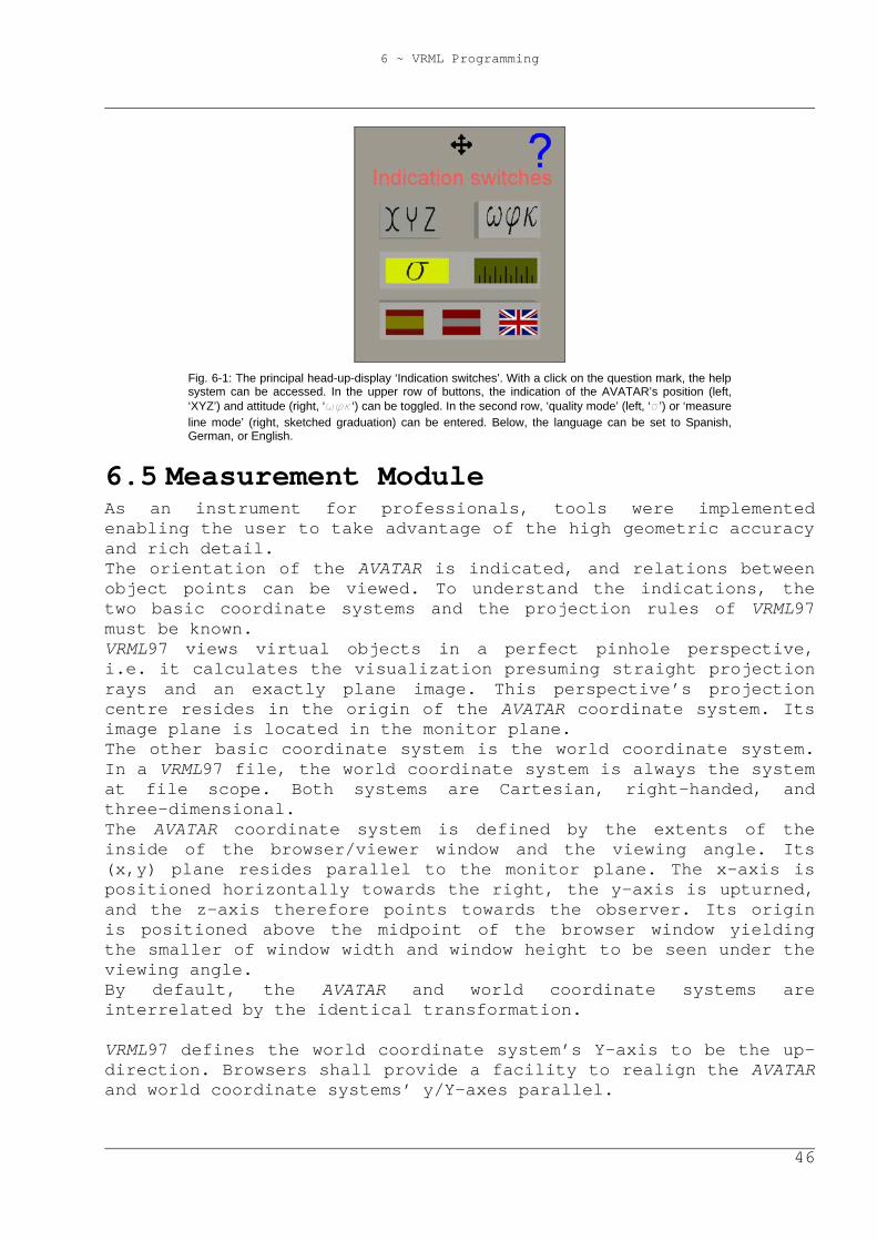
6.4 Head-Up-Displays So-called ‘head-up-displays’ (HUD’s) were programmed to display information to the user, independent from the AVATAR’s position and attitude. These displays were realized as objects in virtual space that execute the same transformations as the AVATAR. This way, the HUD’s stay in the same position in relation to the AVATAR. Furthermore, the two-dimensional position of an HUD on the monitor plane can be altered in the field of view. This can be useful, if the HUD hides some part of the model. Using the dynamic facilities of VRML97, numerical and literal values are sent to and used by the HUD. Javascript scripts were written to calculate the parameters shown on the displays. On the central HUD with the title ‘Indication switches’ (cf. Fig. 6-1), program features can be set. The numerical indication of the AVATAR’s position and attitude (cf. chapter 6.5.1) can be toggled with the two buttons in the first row. In the second row, ‘quality mode’ (left button, cf. chapter 6.5.2) or ‘measure line mode’ (right button, cf. chapter 6.5.3) can be entered. In the lower row, the language can be switched to Spanish, German or English (i.e. the language of HUD titles, of the help system, and of objects that display non-geometric information, cf. chapter 6.3). With a click on the question mark on the upper right, the help system (cf. chapter 6.6.1) can be accessed.
6 ~ VRML Programming
46
Fig. 6-1: The principal head-up-display ‘Indication switches’. With a click on the question mark, the help system can be accessed. In the upper row of buttons, the indication of the AVATAR’s position (left, ‘XYZ’) and attitude (right, ‘wfk‘) can be toggled. In the second row, ‘quality mode’ (left, ‘s’) or ‘measure line mode’ (right, sketched graduation) can be entered. Below, the language can be set to Spanish, German, or English.
6.5 Measurement Module As an instrument for professionals, tools were implemented enabling the user to take advantage of the high geometric accuracy and rich detail. The orientation of the AVATAR is indicated, and relations between object points can be viewed. To understand the indications, the two basic coordinate systems and the projection rules of VRML97 must be known. VRML97 views virtual objects in a perfect pinhole perspective, i.e. it calculates the visualization presuming straight projection rays and an exactly plane image. This perspective’s projection centre resides in the origin of the AVATAR coordinate system. Its image plane is located in the monitor plane. The other basic coordinate system is the world coordinate system. In a VRML97 file, the world coordinate system is always the system at file scope. Both systems are Cartesian, right-handed, and three-dimensional. The AVATAR coordinate system is defined by the extents of the inside of the browser/viewer window and the viewing angle. Its (x,y) plane resides parallel to the monitor plane. The x-axis is positioned horizontally towards the right, the y-axis is upturned, and the z-axis therefore points towards the observer. Its origin is positioned above the midpoint of the browser window yielding the smaller of window width and window height to be seen under the viewing angle. By default, the AVATAR and world coordinate systems are interrelated by the identical transformation. VRML97 defines the world coordinate system’s Y-axis to be the up-direction. Browsers shall provide a facility to realign the AVATAR and world coordinate systems’ y/Y-axes parallel.
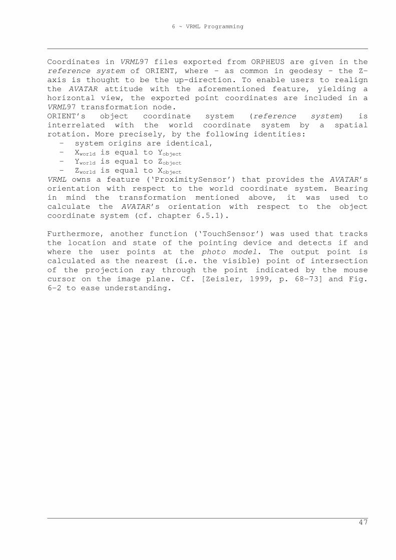
6 ~ VRML Programming
47
Coordinates in VRML97 files exported from ORPHEUS are given in the reference system of ORIENT, where – as common in geodesy - the Z-axis is thought to be the up-direction. To enable users to realign the AVATAR attitude with the aforementioned feature, yielding a horizontal view, the exported point coordinates are included in a VRML97 transformation node. ORIENT’s object coordinate system (reference system) is interrelated with the world coordinate system by a spatial rotation. More precisely, by the following identities:
- system origins are identical, - Xworld is equal to Yobject - Yworld is equal to Zobject - Zworld is equal to Xobject
VRML owns a feature (‘ProximitySensor’) that provides the AVATAR’s orientation with respect to the world coordinate system. Bearing in mind the transformation mentioned above, it was used to calculate the AVATAR’s orientation with respect to the object coordinate system (cf. chapter 6.5.1). Furthermore, another function (‘TouchSensor’) was used that tracks the location and state of the pointing device and detects if and where the user points at the photo model. The output point is calculated as the nearest (i.e. the visible) point of intersection of the projection ray through the point indicated by the mouse cursor on the image plane. Cf. [Zeisler, 1999, p. 68-73] and Fig. 6-2 to ease understanding.
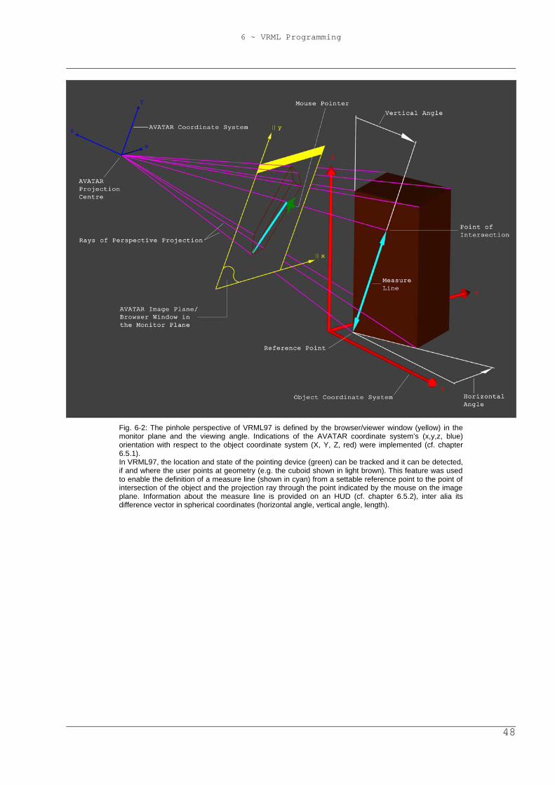
6 ~ VRML Programming
48
Fig. 6-2: The pinhole perspective of VRML97 is defined by the browser/viewer window (yellow) in the monitor plane and the viewing angle. Indications of the AVATAR coordinate system’s (x,y,z, blue) orientation with respect to the object coordinate system (X, Y, Z, red) were implemented (cf. chapter 6.5.1). In VRML97, the location and state of the pointing device (green) can be tracked and it can be detected, if and where the user points at geometry (e.g. the cuboid shown in light brown). This feature was used to enable the definition of a measure line (shown in cyan) from a settable reference point to the point of intersection of the object and the projection ray through the point indicated by the mouse on the image plane. Information about the measure line is provided on an HUD (cf. chapter 6.5.2), inter alia its difference vector in spherical coordinates (horizontal angle, vertical angle, length).
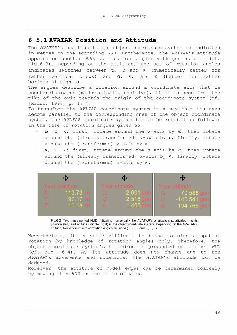
6 ~ VRML Programming
49
6.5.1 AVATAR Position and Attitude The AVATAR’s position in the object coordinate system is indicated in metres on the according HUD. Furthermore, the AVATAR’s attitude appears on another HUD, as rotation angles with gon as unit (cf. Fig.6-3). Depending on the attitude, the set of rotation angles indicated switches between ω, φ and κ (numerically better for rather vertical views) and α, ν, and κ (better for rather horizontal sights). The angles describe a rotation around a coordinate axis that is counterclockwise (mathematically positive), if it is seen from the pike of the axis towards the origin of the coordinate system (cf. [Kraus, 1996, p. 16]). To transform the AVATAR coordinate system in a way that its axes become parallel to the corresponding ones of the object coordinate system, the AVATAR coordinate system has to be rotated as follows: in the case of rotation angles given as
- ω, φ, κ: first, rotate around the x-axis by ω, then rotate around the (already transformed) y-axis by φ, finally, rotate around the (transformed) z-axis by κ.
- α, ν, κ: first, rotate around the z-axis by α, then rotate around the (already transformed) x-axis by ν, finally, rotate around the (transformed) z-axis by κ.
Fig.6-3: Two implemented HUD indicating numerically the AVATAR’s orientation, subdivided into its position (left) and attitude (middle, right) in the object coordinate system. Depending on the AVATAR’s attitude, two different sets of rotation angles are used (w, f, k and a, n, k).
Nevertheless, it is quite difficult to bring to mind a spatial rotation by knowledge of rotation angles only. Therefore, the object coordinate system’s trihedron is presented on another HUD (cf. Fig. 6-4). As its attitude does not change due to the AVATAR’s movements and rotations, the AVATAR’s attitude can be deduced. Moreover, the attitude of model edges can be determined coarsely by moving this HUD in the field of view.
6 ~ VRML Programming
50
Fig. 6-4: Implemented HUD presenting the object coordinate system’s trihedron. Independent from the AVATAR’s attitude, the displayed coordinate axes stay parallel to the ones of the object coordinate system. Thus, the AVATAR’s attitude can be deduced. Furthermore, the attitude of model edges can be determined coarsely by shifting the HUD in the field of view.
6.5.2 Quality Mode Having entered ‘quality mode’, yellow spheres appear at the positions of vertices and other adjusted points. Furthermore, at positions where used photogrammes were taken, models of a camera come into view, having the adjusted orientation. Green spheres indicate points of the geodetic station network, where models of a theodolite are located yielding the tilting axes having the mean height of the respective station. By moving the mouse cursor to one of the spheres, the according point’s quality can be inspected by means of accuracy and control. These characteristics are indicated both numerically and graphically. When the mouse pointer resides over a sphere, the corresponding point’s object coordinates appear on an HUD. Furthermore, its accuracy is indicated as standard deviations in the three coordinate directions. Moreover, the number of observation equations used to determine the point in the final adjustment is shown. To indicate the point’s accuracy graphically, an ellisoid appears in magenta. Its semi-axes are parallel to the object coordinate system, having the lengths of ten times the respective standard deviations. Control is indicated graphically as line segments. Only real observations, i.e. image and polar ones are shown. Yellow line segments from a camera model indicate the observation of at least one image coordinate in the respective image, whereas red lines represent the observation of at least one polar angle from a geodetic station. Green lines indicate observations of a station from another one, where in addition to polar angles, also the distance may have been used in the adjustment. Furthermore, the respective bundle of observations can be visualized by touching a model of the camera or the theodolite.
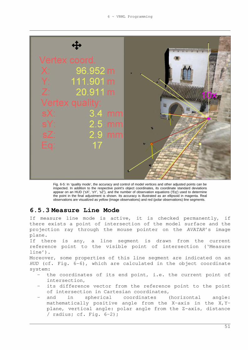
6 ~ VRML Programming
51
Fig. 6-5: In ‘quality mode’, the accuracy and control of model vertices and other adjusted points can be inspected. In addition to the respective point’s object coordinates, its coordinate standard deviations appear on an HUD (‘sX’, ‘sY’, ‘sZ’), and the number of observation equations (‘Eq’) used to determine the point in the final adjustment is shown. Its accuracy is illustrated as an ellipsoid in magenta. Real observations are visualized as yellow (image observations) and red (polar observations) line segments.
6.5.3 Measure Line Mode If measure line mode is active, it is checked permanently, if there exists a point of intersection of the model surface and the projection ray through the mouse pointer on the AVATAR’s image plane. If there is any, a line segment is drawn from the current reference point to the visible point of intersection (‘Measure line’). Moreover, some properties of this line segment are indicated on an HUD (cf. Fig. 6-6), which are calculated in the object coordinate system:
- the coordinates of its end point, i.e. the current point of intersection,
- its difference vector from the reference point to the point of intersection in Cartesian coordinates,
- and in spherical coordinates (horizontal angle: mathematically positive angle from the X-axis in the X,Y-plane, vertical angle: polar angle from the Z-axis, distance / radius; cf. Fig. 6-2);
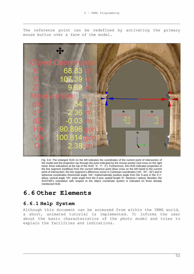
6 ~ VRML Programming
52
The reference point can be redefined by activating the primary mouse button over a face of the model.
Fig. 6-6: The enlarged HUD on the left indicates the coordinates of the current point of intersection of the model and the projection ray through the point indicated by the mouse pointer (red cross on the right hand, three indications at the top of the HUD: ‘X’, ‘Y’, ‘Z’). Furthermore, this HUD indicates properties of the line segment (red/blue) from the current reference point (blue cross on the left hand) to the current point of intersection: the line segment’s difference vector in Cartesian coordinates (‘dX’, ‘dY’, ‘dZ’) and in spherical coordinates (horizontal angle ‘HA’: mathematically positive angle from the X-axis in the X,Y-plane; vertical angle ‘VA’: polar angle from the Z-axis; spatial length ‘D’: distance / radius). Besides, the AVATAR’s orientation with respect to the object coordinate system is indicated on three already mentioned HUD.
6.6 Other Elements 6.6.1 Help System Although this document can be accessed from within the VRML world, a short, animated tutorial is implemented. It informs the user about the basic characteristics of the photo model and tries to explain the facilities and indications.
6 ~ VRML Programming
53
6.6.2 Orthophoto as Underlay As a nice gimmick, an orthophoto originally made for a scale of 1:5.000 is presented as an underlay of the model. Unfortunately, it obviously had been rectified without a surface model. Thus, buildings on the ground look like toppled down, and a view together with the model nearby would be disgusting. Therefore, it is only visible if viewed from 30m above ground.
6.6.3 Automatic Door To invite the user to the church, the north-western entrance door, which lies on the animation route, opens its leaves when the viewer is nearby.
6.6.4 Audio Scenery For a better cognition of the age of the historical site, some adequate Gregorian choral can be heard as background.
6.7 Program Hierarchy The photo model should be visualized well on different computers, operating systems, browsers / viewers and plug-ins. By usage of VRML code and included Javascript scripts exclusively, this cannot be guaranteed, because this way, the browser window extents cannot be queried from within the VRML scene. Depending on the extents (in pixels) of the interior of the browser window, the HUD might not be displayed well. In the case of a small window, they may get out of sight. In the other case, they can get too near to the centre of the window, occluding the photo model. Even though the HUD can be moved in the field of view, this is annoying work. To solve this, there were three solutions considered:
- implementation of Java™ classes; the VRML specifications define an interface to a Java™ platform. This solution would have required the installation of a Java™ runtime environment on the viewing computer and would probably have slowed down loading the VRML scene, cf. [Zeisler, 1999, p. 13-14]. For that reasons, the implementation of Java™ code had already been rejected during the programming phase of HUD’s.
- usage of an interface to the browser not using Java (EAI, external authoring interface); this solution would have been browser- and plug-in-dependent, although this type of interface recently has been standardized (cf. [VRML97, 2001]).
- embedding of the VRML scene into an html-file; using Javascript in html, a script can query the monitor resolution. Still, it is not possible to pass values to the embedded VRML scene, but according to the resolution before the load of the model, versions of the photo model’s parent file with different HUD offsets can be started.
6 ~ VRML Programming
54
Javascript scripts already had been implemented in VRML code to calculate data indicated on HUD’s, because all common browsers can interpret this code. Nevertheless, it is possible that browsers have set the Javascript-interpreter deactivated. Anyway, the solution using Javascript scripts in html files was chosen due to the aforementioned reasons. As mentioned in chapter 5.3, versions of the photo model with different levels of requirements on the viewing computer and its internet connection should be provided. Therefore, the author decided to provide two basic versions of the model:
- a simple model with high compressed texture and without Javascript code, therefore not containing HUD’s and
- an advanced model, providing highest texture quality and full functionality.
The two versions can be accessed via a simple start html file, where it is cited that the browser must have Javascript activated before loading the advanced model. The simple model does not require a Javascript-interpreter. On load, the extents of the browser window are not directed by the VRML world. Only Netscape© implements a Javascript function to query the interior extent of the browser window. To avoid further complications due to different width to height ratios, the standard ratio 4:3 of monitors is presumed to set HUD offsets. Activating the link to the advanced model, a Javascript script queries the monitor resolution and opens a new browser window of full screen size. Moreover, everything possible is deactivated that could influence the mentioned ratio, i.e. address bar, menu bar, scroll bars, status bar, tool bar. Unfortunately, html is not strictly standardized. Netscape© Navigator and Microsoft© Internet Explorer, as two widespread browsers with a long history, do not support common directives to embed VRML scenes. Therefore, on load of the advanced model, the aforementioned Javascript script also queries the browser type and opens the html file according to the used browser. VRML programming work was much more enjoyable than coding html, as VRML seems to be implemented into the diverse plug-ins quite strictly. VRML supports some characteristics of object oriented programming. So-called prototypes can be defined with proprietary data and functions. A good example to take advantage of this ability could be the HUD-prototype. It is defined once and instantiated five times, with various duties and appearances. In addition, the Inform-prototype to display non-geometric information (cf. chapter 6.3) is defined only once and instantiated thrice, with different texts in three language versions. Although a prototype can imply other prototypes and data contained by them can be altered, it cannot inherit data and functions from ancestors.
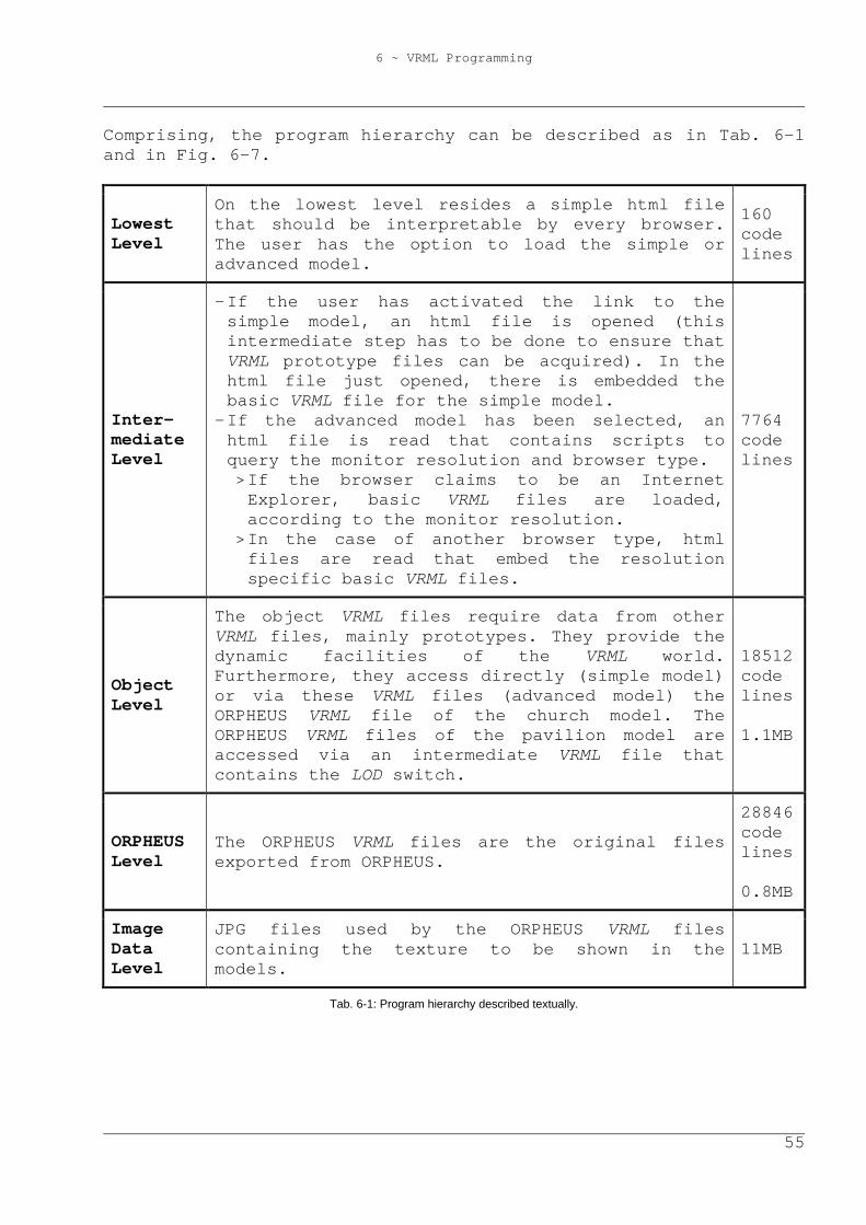
6 ~ VRML Programming
55
Comprising, the program hierarchy can be described as in Tab. 6-1 and in Fig. 6-7.
Lowest Level
On the lowest level resides a simple html file that should be interpretable by every browser. The user has the option to load the simple or advanced model.
160 code lines
Inter-mediate Level
- If the user has activated the link to the simple model, an html file is opened (this intermediate step has to be done to ensure that VRML prototype files can be acquired). In the html file just opened, there is embedded the basic VRML file for the simple model.
- If the advanced model has been selected, an html file is read that contains scripts to query the monitor resolution and browser type. > If the browser claims to be an Internet Explorer, basic VRML files are loaded, according to the monitor resolution.
> In the case of another browser type, html files are read that embed the resolution specific basic VRML files.
7764 code lines
Object Level
The object VRML files require data from other VRML files, mainly prototypes. They provide the dynamic facilities of the VRML world. Furthermore, they access directly (simple model) or via these VRML files (advanced model) the ORPHEUS VRML file of the church model. The ORPHEUS VRML files of the pavilion model are accessed via an intermediate VRML file that contains the LOD switch.
18512 code lines 1.1MB
ORPHEUS Level
The ORPHEUS VRML files are the original files exported from ORPHEUS.
28846 code lines 0.8MB
Image Data Level
JPG files used by the ORPHEUS VRML files containing the texture to be shown in the models.
11MB
Tab. 6-1: Program hierarchy described textually.
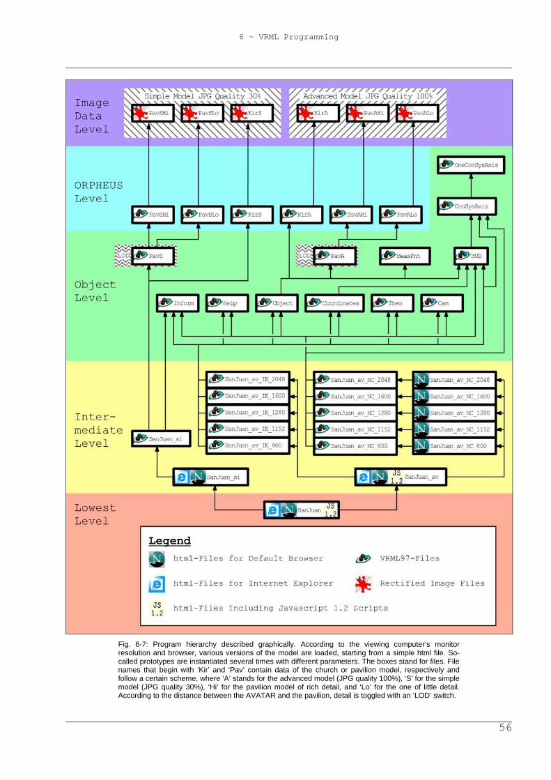
6 ~ VRML Programming
56
Fig. 6-7: Program hierarchy described graphically. According to the viewing computer’s monitor resolution and browser, various versions of the model are loaded, starting from a simple html file. So-called prototypes are instantiated several times with different parameters. The boxes stand for files. File names that begin with ‘Kir’ and ‘Pav’ contain data of the church or pavilion model, respectively and follow a certain scheme, where ‘A’ stands for the advanced model (JPG quality 100%), ‘S’ for the simple model (JPG quality 30%), ‘Hi’ for the pavilion model of rich detail, and ‘Lo’ for the one of little detail. According to the distance between the AVATAR and the pavilion, detail is toggled with an ‘LOD’ switch.
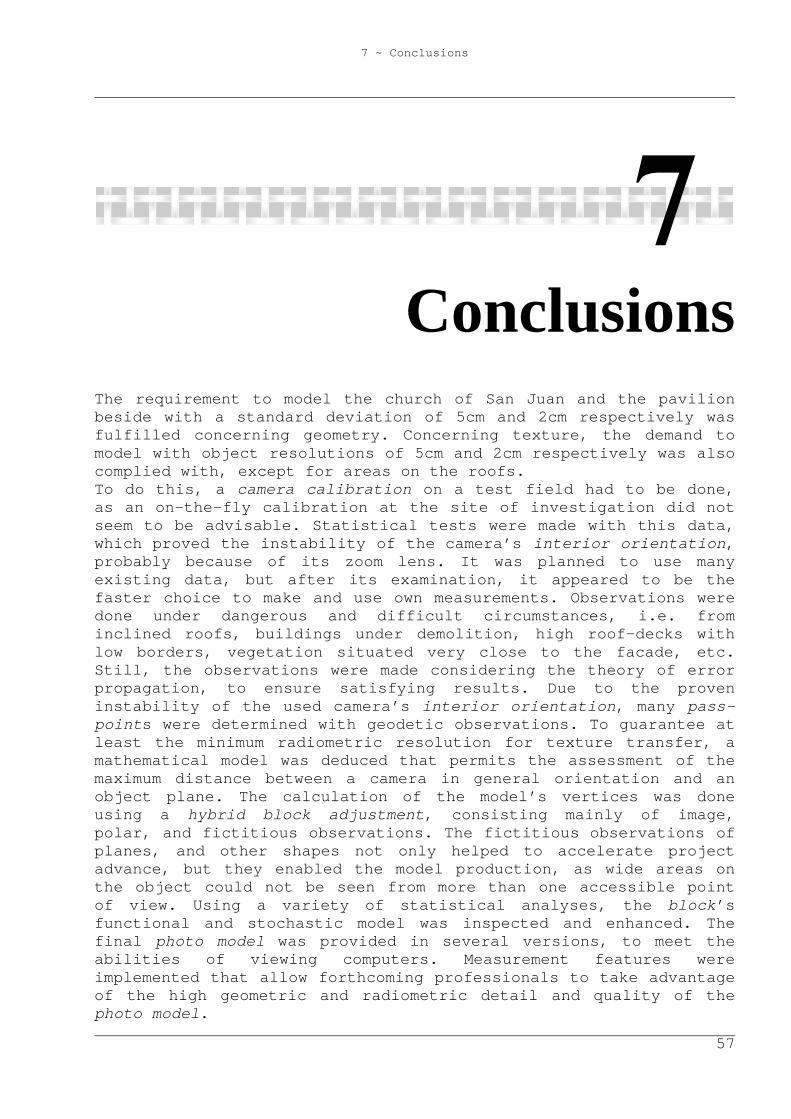
7 ~ Conclusions
57
7 Conclusions The requirement to model the church of San Juan and the pavilion beside with a standard deviation of 5cm and 2cm respectively was fulfilled concerning geometry. Concerning texture, the demand to model with object resolutions of 5cm and 2cm respectively was also complied with, except for areas on the roofs. To do this, a camera calibration on a test field had to be done, as an on-the-fly calibration at the site of investigation did not seem to be advisable. Statistical tests were made with this data, which proved the instability of the camera’s interior orientation, probably because of its zoom lens. It was planned to use many existing data, but after its examination, it appeared to be the faster choice to make and use own measurements. Observations were done under dangerous and difficult circumstances, i.e. from inclined roofs, buildings under demolition, high roof-decks with low borders, vegetation situated very close to the facade, etc. Still, the observations were made considering the theory of error propagation, to ensure satisfying results. Due to the proven instability of the used camera’s interior orientation, many pass-points were determined with geodetic observations. To guarantee at least the minimum radiometric resolution for texture transfer, a mathematical model was deduced that permits the assessment of the maximum distance between a camera in general orientation and an object plane. The calculation of the model’s vertices was done using a hybrid block adjustment, consisting mainly of image, polar, and fictitious observations. The fictitious observations of planes, and other shapes not only helped to accelerate project advance, but they enabled the model production, as wide areas on the object could not be seen from more than one accessible point of view. Using a variety of statistical analyses, the block’s functional and stochastic model was inspected and enhanced. The final photo model was provided in several versions, to meet the abilities of viewing computers. Measurement features were implemented that allow forthcoming professionals to take advantage of the high geometric and radiometric detail and quality of the photo model.
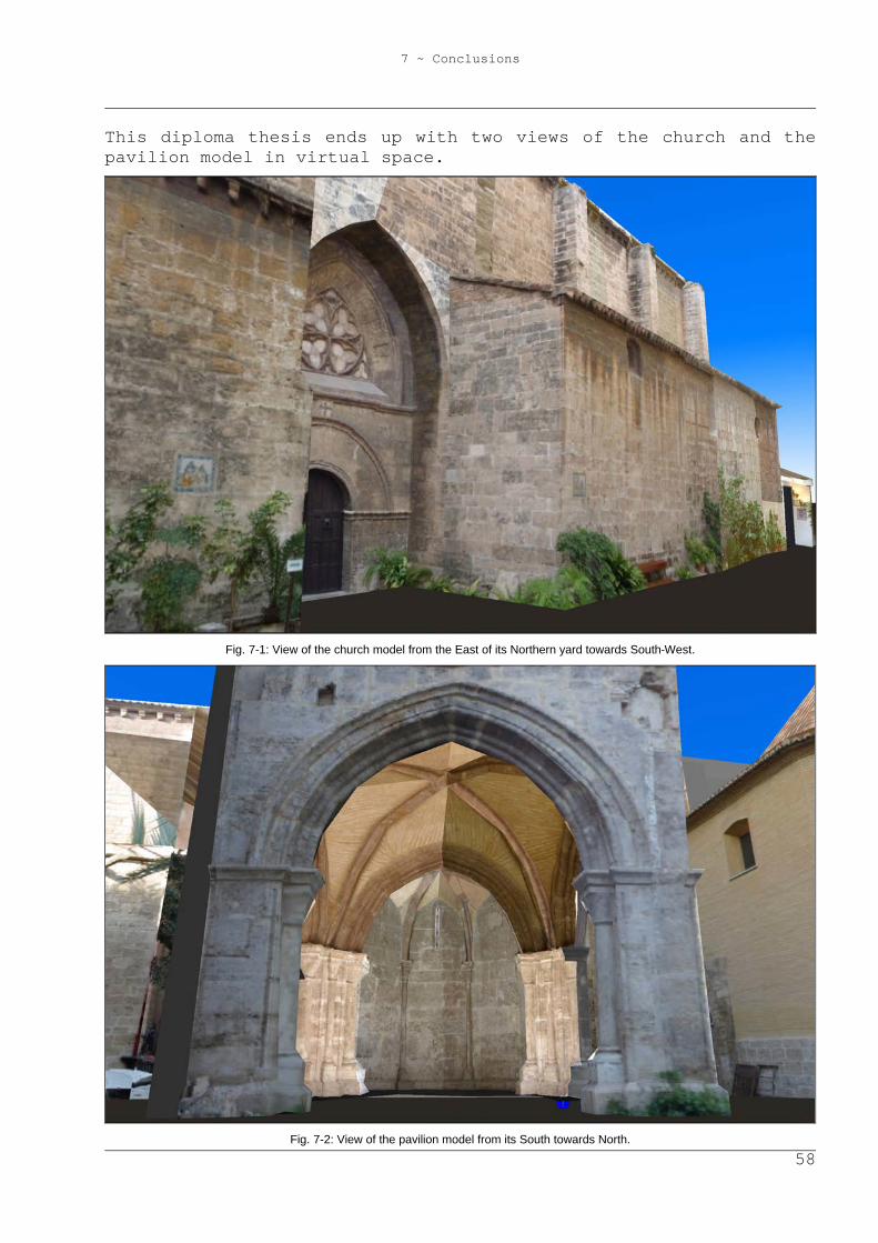
7 ~ Conclusions
58
This diploma thesis ends up with two views of the church and the pavilion model in virtual space.
Fig. 7-1: View of the church model from the East of its Northern yard towards South-West.
Fig. 7-2: View of the pavilion model from its South towards North.

59
Appendix
A ~ Nomenclature
60
A Nomenclature
Some terms mentioned in this document must be understood in a more specific sense than commonly; other ones may not be familiar to the reader. In case they are mentioned throughout the text, they shall be explained in the table stated below.
AVATAR Abstract representation of the user in the virtual space of a VRML world
Block Photogrammetric, mathematical model used for object reconstruction. A block contains (interrelated, redundant) observations that are functions of (unknown) parameters (e.g. point coordinates, interior and exterior orientations). Furthermore, the definition of the reference system is part of a block. Remark: the corresponding geodetic model is called ‘network’
Block adjustment Calculation of most probable values, accuracies, and correlations of a block’s observations and parameters
Camera calibration
Determination of a camera’s interior orientation
Control point Point with known/presumed reference system coordinates. Therefore a control point is part of the reference system definition
(Model) Edge Straight line segment connecting two vertices
Exterior orientation
Position and attitude of a camera with respect to the reference system
A ~ Nomenclature
61
(Model) Face Polygonal surface area that is bounded by edges
Gestalt observation
Assumption of a zero-distance between a point and some kind of shape, e.g. the supposition that a point resides in a plane
HUD ‘Head-up-display’; an indication that stays in the field of view, unaffected from the AVATAR’s movements
Hybrid block Block containing in addition to photogrammetric observations also ones of other type, e.g. geodetic or Gestalt observations
Image coordinate system
Coordinate system based on a camera’s image area wherein the interior orientation is defined
Interior orientation
Set of camera parameters that describe the path of projection rays from the entrance into the lens system to the film or sensor chip, respectively; furthermore, the parameters specify the image area
LOD ‘Level of detail’; VRML function that is used to switch between different amounts of detail or complexity of (a partition of) the viewed model, depending on the distance between the AVATAR and a certain point of the model/the partition of the model
Non-metric camera Camera that is not designed to facilitate the accurate metric evaluation of photographs taken with it
Pass-point Point that is observed (also) geodetically, to be used for image orientation
Photogramme Analogue or digital photograph to be used for metric evaluation
Photogrammetry Science of object reconstruction by touchless measurements, concerning both geometry and radiometry. Furthermore, all related aspects are part of photogrammetry
A ~ Nomenclature
62
Photo model Virtual spatial model of a real object’s surface, calculated with photogrammetric techniques. Rectified image texture is applied to the model’s faces. This texture is a mapping of photogrammes of the object
Reference system Principal coordinate system of a block where all other coordinate systems are referenced to
Tie-point Point that is observed in two or more photogrammes to enhance block stability
VCA ‘Variance Components Analysis’; estimation of proposals for the a priori standard deviations of sets of observations with the same accuracy
(Model) Vertex Corner of a photo model, often a tie- or pass-point
VRML ‘Virtual Reality Modelling Language’; file format for the description of interactive, spatial objects
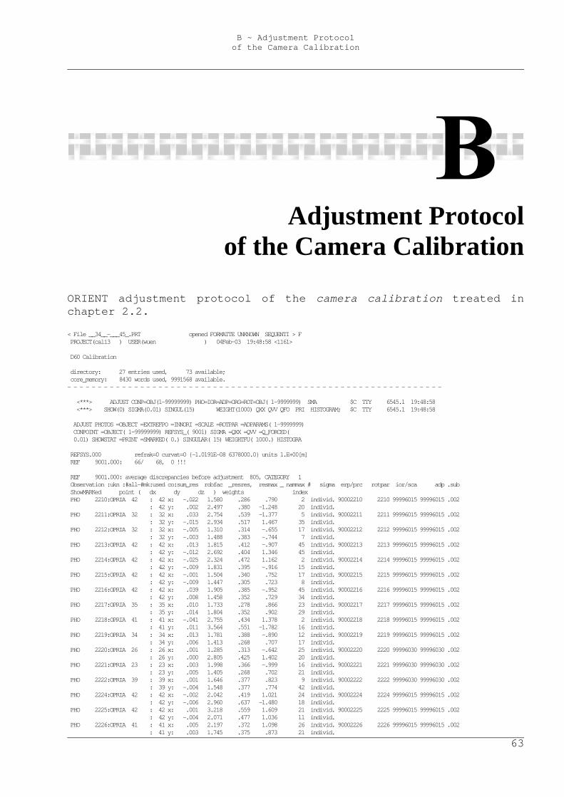
B ~ Adjustment Protocol of the Camera Calibration
63
B Adjustment Protocol of the Camera Calibration
ORIENT adjustment protocol of the camera calibration treated in chapter 2.2. < File __34__-___45_.PRT opened FORMATTE UNKNOWN SEQUENTI > F PROJECT(cali3 ) USER(wuen ) 04Feb-03 19:48:58 <1161> D60 Calibration directory: 27 entries used, 73 available; core_memory: 8430 words used, 9991568 available. - - - - - - - - - - - - - - - - - - - - - - - - - - - - - - - - - - - - - - - - - - - - - - - - - - - - - - - - - - - - - - <***> ADJUST CONP=OBJ(1-99999999) PHO=IOR=ADP=ORG=ROT=OBJ( 1-9999999) SMA $C TTY 6545.1 19:48:58 <***> SHOW(0) SIGMA(0.01) SINGUL(15) WEIGHT(1000) QXX QVV QFO PRI HISTOGRAM; $C TTY 6545.1 19:48:58 ADJUST PHOTOS =OBJECT =EXTREFPO =INNORI =SCALE =ROTPAR =ADPARAMS( 1-9999999) CONPOINT =OBJECT( 1-99999999) REFSYS_( 9001) SIGMA =QXX =QVV =Q_FORCED( 0.01) SHOWSTAT =PRINT =SMARKED( 0.) SINGULAR( 15) WEIGHTFU( 1000.) HISTOGRA REFSYS.000 refrak=0 curvat=0 {-1.0191E-08 6378000.0} units 1.E+00[m] REF 9001.000: 66/ 68, 0 !!! REF 9001.000: average discrepancies before adjustment 805, CATEGORY 1 Observation :ukn :#all-#mk:used co:sum_res robfac _resres, resmax _ nammax # sigma erp/prc rotpar ior/sca adp .sub ShowMARKed point ( dx dy dz ) weights index PHO 2210:OPRIA 42 : 42 x: -.022 1.580 .286 .790 2 individ. 90002210 2210 99996015 99996015 .002 : 42 y: .002 2.497 .380 -1.248 20 individ. PHO 2211:OPRIA 32 : 32 x: .033 2.754 .539 -1.377 5 individ. 90002211 2211 99996015 99996015 .002 : 32 y: -.015 2.934 .517 1.467 35 individ. PHO 2212:OPRIA 32 : 32 x: -.005 1.310 .314 -.655 17 individ. 90002212 2212 99996015 99996015 .002 : 32 y: -.003 1.488 .383 -.744 7 individ. PHO 2213:OPRIA 42 : 42 x: .013 1.815 .412 -.907 45 individ. 90002213 2213 99996015 99996015 .002 : 42 y: -.012 2.692 .404 1.346 45 individ. PHO 2214:OPRIA 42 : 42 x: -.025 2.324 .472 1.162 2 individ. 90002214 2214 99996015 99996015 .002 : 42 y: -.009 1.831 .395 -.916 15 individ. PHO 2215:OPRIA 42 : 42 x: -.001 1.504 .340 .752 17 individ. 90002215 2215 99996015 99996015 .002 : 42 y: -.009 1.447 .305 .723 8 individ. PHO 2216:OPRIA 42 : 42 x: .039 1.905 .385 -.952 45 individ. 90002216 2216 99996015 99996015 .002 : 42 y: .008 1.458 .352 .729 34 individ. PHO 2217:OPRIA 35 : 35 x: .010 1.733 .278 .866 23 individ. 90002217 2217 99996015 99996015 .002 : 35 y: .014 1.804 .352 .902 29 individ. PHO 2218:OPRIA 41 : 41 x: -.041 2.755 .434 1.378 2 individ. 90002218 2218 99996015 99996015 .002 : 41 y: .011 3.564 .551 -1.782 16 individ. PHO 2219:OPRIA 34 : 34 x: .013 1.781 .388 -.890 12 individ. 90002219 2219 99996015 99996015 .002 : 34 y: .006 1.413 .268 .707 17 individ. PHO 2220:OPRIA 26 : 26 x: .001 1.285 .313 -.642 25 individ. 90002220 2220 99996030 99996030 .002 : 26 y: .000 2.805 .425 1.402 20 individ. PHO 2221:OPRIA 23 : 23 x: .003 1.998 .366 -.999 16 individ. 90002221 2221 99996030 99996030 .002 : 23 y: .005 1.405 .268 .702 21 individ. PHO 2222:OPRIA 39 : 39 x: .001 1.646 .377 .823 9 individ. 90002222 2222 99996030 99996030 .002 : 39 y: -.004 1.548 .377 .774 42 individ. PHO 2224:OPRIA 42 : 42 x: -.002 2.042 .419 1.021 24 individ. 90002224 2224 99996015 99996015 .002 : 42 y: -.006 2.960 .637 -1.480 18 individ. PHO 2225:OPRIA 42 : 42 x: .001 3.218 .559 1.609 21 individ. 90002225 2225 99996015 99996015 .002 : 42 y: -.004 2.071 .477 1.036 11 individ. PHO 2226:OPRIA 41 : 41 x: .005 2.197 .372 1.098 26 individ. 90002226 2226 99996015 99996015 .002 : 41 y: .003 1.745 .375 .873 21 individ.
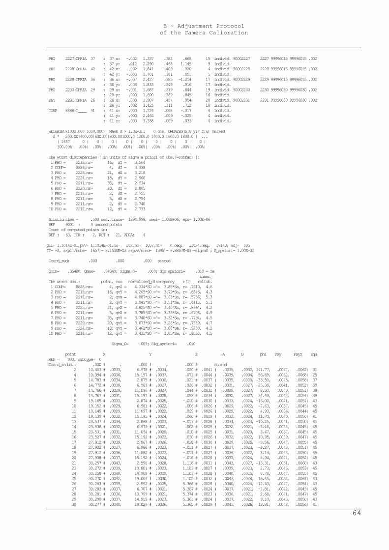
B ~ Adjustment Protocol of the Camera Calibration
64
PHO 2227:OPRIA 37 : 37 x: -.002 1.337 .383 .668 15 individ. 90002227 2227 99996015 99996015 .002 : 37 y: .012 2.290 .466 1.145 9 individ. PHO 2228:OPRIA 42 : 42 x: -.002 1.841 .409 -.920 4 individ. 90002228 2228 99996015 99996015 .002 : 42 y: -.003 1.701 .381 .851 5 individ. PHO 2229:OPRIA 36 : 36 x: -.007 2.427 .385 -1.214 17 individ. 90002229 2229 99996015 99996015 .002 : 36 y: .008 1.833 .349 .916 17 individ. PHO 2230:OPRIA 29 : 29 x: -.001 1.687 .319 .844 19 individ. 90002230 2230 99996030 99996030 .002 : 29 y: .000 1.690 .369 .845 16 individ. PHO 2231:OPRIA 26 : 26 x: -.003 1.907 .457 -.954 20 individ. 90002231 2231 99996030 99996030 .002 : 26 y: .002 1.425 .311 .712 18 individ. CONP 8888:O____ 41 : 41 x: .000 1.724 .008 -.017 4 individ. : 41 y: .000 2.464 .009 -.025 4 individ. : 41 z: .000 3.338 .009 .033 4 individ. WEIGHTFU(1000.000 1000.000), MARK d > 1.0E+31: 0 obs. OMCATEG(x:8 y:7 z:6) marked d * 200.00|400.00|600.00|800.001000.0 1200.0 1400.0 1600.0 1800.0 | ... | 1657 | 0 | 0 | 0 | 0 | 0 | 0 | 0 | 0 | 0 | 100.00%| .00%| .00%| .00%| .00%| .00%| .00%| .00%| .00%| .00%| The worst discrepancies [ in units of sigma-a-priori of obs.(=robfac) ]: 1 PHO = 2218,nr= 16, dY = 3.564 2 CONP= 8888,nr= 4, dZ = 3.338 3 PHO = 2225,nr= 21, dX = 3.218 4 PHO = 2224,nr= 18, dY = 2.960 5 PHO = 2211,nr= 35, dY = 2.934 6 PHO = 2220,nr= 20, dY = 2.805 7 PHO = 2218,nr= 2, dX = 2.755 8 PHO = 2211,nr= 5, dX = 2.754 9 PHO = 2211,nr= 2, dY = 2.740 10 PHO = 2218,nr= 12, dY = 2.733 Solutiontime = .500 sec.,trace= 1394.998, swei= 1.00E+06, eps= 1.00E-06 REF 9001 : 3 unused points Count of computed points in: REF : 63, IOR : 2, ROT : 21, ADPA: 4 pll= 1.1014E-01,pvv= 1.1014E-01,nx= 262,no= 1657,nt= 0,oeq: 33624,neq: 37143, adj= 805 IT= -2, s(pll/nobs= 1657)= 8.1530E-03 s(pvv/nred= 1395)= 8.8857E-03 =sigma0 ; S_apriori= 1.00E-02 Coord_red: .000 .000 .000 stored Qmin= .35480, Qmax= .94849; Sigma_0= .009; Sig_apriori= .010 = Sa inner_ The worst obs.: point, coo normalized_discrepancy r(i) reliab. 1 CONP= 8888,nr= 4, qvZ = 4.334*S0 =̂ = 3.85*Sa, r= .7510, 4.6 2 PHO = 2218,nr= 16, qvY = 4.265*S0 =̂ = 3.79*Sa, r= .8846, 4.3 3 PHO = 2218,nr= 2, qvX = 4.087*S0 =̂ = 3.63*Sa, r= .5756, 5.3 4 PHO = 2211,nr= 2, qvY = 3.945*S0 =̂ = 3.51*Sa, r= .6113, 5.1 5 PHO = 2225,nr= 21, qvX = 3.825*S0 =̂ = 3.40*Sa, r= .8964, 4.2 6 PHO = 2211,nr= 5, qvX = 3.785*S0 =̂ = 3.36*Sa, r= .6706, 4.9 7 PHO = 2211,nr= 35, qvY = 3.740*S0 =̂ = 3.32*Sa, r= .7794, 4.5 8 PHO = 2220,nr= 20, qvY = 3.673*S0 =̂ = 3.26*Sa, r= .7389, 4.7 9 PHO = 2224,nr= 18, qvY = 3.462*S0 =̂ = 3.08*Sa, r= .9259, 4.2 10 PHO = 2218,nr= 12, qvY = 3.432*S0 =̂ = 3.05*Sa, r= .8033, 4.5 Sigma_0= .009; Sig_apriori= .010 point X Y Z A B phi Pxy Pxyz Equ REF = 9001 subtype= 0 Coord_reduc.: .000 # , .000 # , .000 # stored 2 10.403 # .0033, 6.978 # .0034, .020 # .0041 ( .0035, .0032, 141.77, .0047, .0062) 31 4 10.394 # .0036, 15.197 # .0037, .071 # .0044 ( .0039, .0034, 56.69, .0052, .0068) 25 5 14.783 # .0034, 2.875 # .0030, .021 # .0037 ( .0035, .0028, -33.50, .0045, .0058) 37 6 14.772 # .0030, 6.983 # .0027, .026 # .0032 ( .0031, .0027, -25.38, .0041, .0052) 39 7 14.766 # .0029, 11.096 # .0027, .044 # .0032 ( .0029, .0027, 8.50, .0040, .0051) 39 8 14.767 # .0031, 15.197 # .0028, .053 # .0034 ( .0032, .0027, 34.49, .0042, .0054) 39 9 19.165 # .0033, 2.874 # .0025, -.010 # .0030 ( .0033, .0024, -16.00, .0041, .0051) 43 10 19.152 # .0029, 6.981 # .0022, .006 # .0026 ( .0029, .0022, -7.63, .0037, .0045) 45 11 19.149 # .0029, 11.097 # .0022, .029 # .0026 ( .0029, .0022, 4.93, .0036, .0044) 45 12 19.139 # .0032, 15.195 # .0024, .060 # .0029 ( .0032, .0024, 11.70, .0040, .0050) 41 13 23.537 # .0034, 2.868 # .0023, -.017 # .0028 ( .0034, .0023, -10.25, .0041, .0050) 45 14 23.538 # .0032, 6.979 # .0021, .002 # .0025 ( .0032, .0021, -3.46, .0038, .0045) 45 15 23.531 # .0031, 11.094 # .0020, .010 # .0025 ( .0031, .0020, 3.47, .0037, .0045) 45 16 23.527 # .0032, 15.192 # .0022, .030 # .0026 ( .0032, .0022, 10.95, .0039, .0047) 45 17 27.912 # .0039, 2.867 # .0026, -.028 # .0030 ( .0039, .0025, -9.56, .0047, .0055) 45 18 27.902 # .0037, 6.966 # .0023, -.011 # .0027 ( .0037, .0023, -3.27, .0043, .0051) 45 19 27.912 # .0036, 11.082 # .0022, -.011 # .0027 ( .0036, .0022, 3.14, .0043, .0050) 45 20 27.908 # .0037, 15.192 # .0024, -.018 # .0028 ( .0037, .0024, 8.94, .0044, .0052) 45 21 30.257 # .0043, 2.596 # .0028, 1.116 # .0031 ( .0043, .0027, -13.31, .0051, .0060) 43 23 30.272 # .0039, 10.801 # .0023, 1.103 # .0027 ( .0039, .0023, 2.73, .0046, .0053) 45 24 30.258 # .0040, 14.908 # .0025, 1.101 # .0028 ( .0040, .0025, 8.78, .0047, .0055) 45 25 30.270 # .0042, 19.004 # .0030, 1.105 # .0032 ( .0043, .0028, 16.45, .0052, .0061) 43 26 30.283 # .0039, 2.592 # .0025, 5.366 # .0028 ( .0040, .0024, -12.43, .0047, .0054) 43 27 30.283 # .0037, 6.707 # .0021, 5.367 # .0024 ( .0037, .0021, -3.81, .0042, .0049) 45 28 30.281 # .0036, 10.799 # .0021, 5.374 # .0023 ( .0036, .0021, 2.68, .0041, .0047) 45 29 30.290 # .0037, 14.915 # .0023, 5.361 # .0024 ( .0037, .0022, 9.10, .0043, .0050) 43 30 30.277 # .0040, 19.029 # .0026, 5.365 # .0029 ( .0041, .0026, 13.81, .0048, .0056) 41
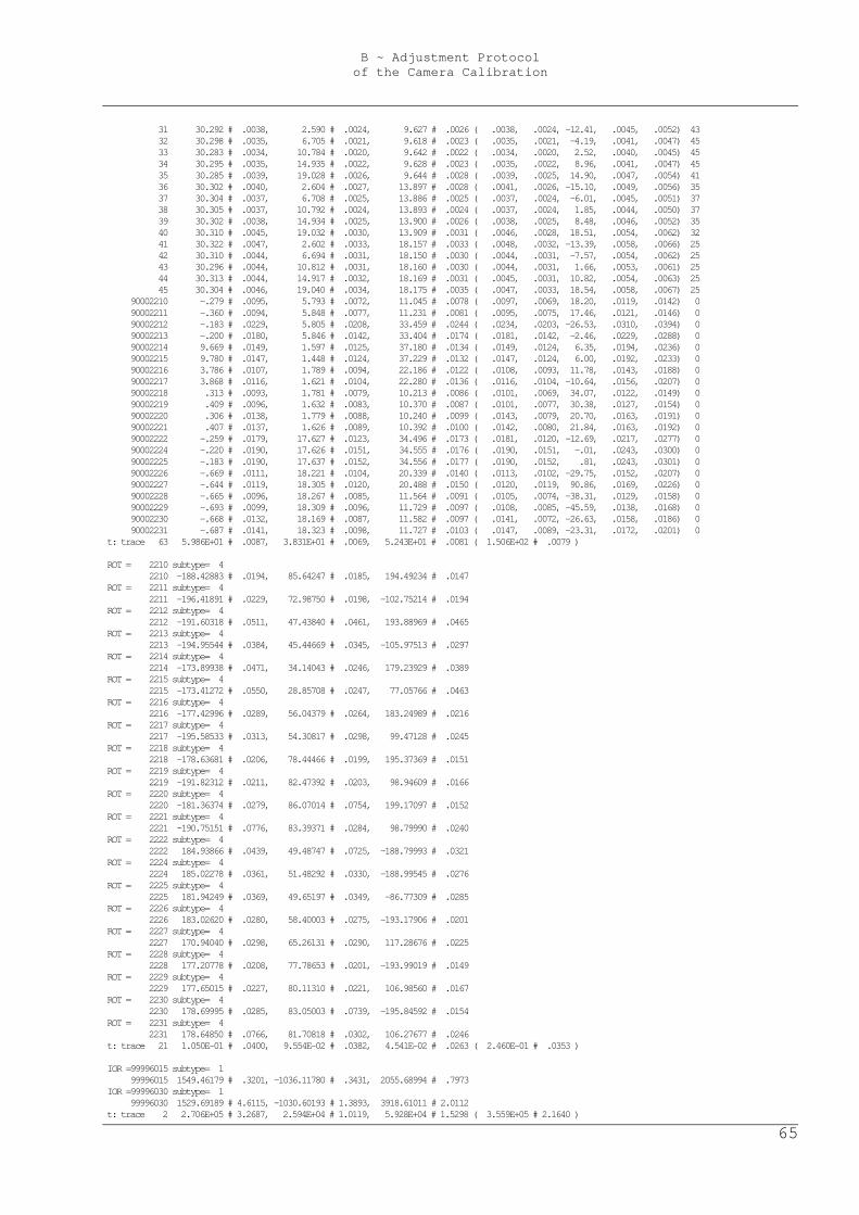
B ~ Adjustment Protocol of the Camera Calibration
65
31 30.292 # .0038, 2.590 # .0024, 9.627 # .0026 ( .0038, .0024, -12.41, .0045, .0052) 43 32 30.298 # .0035, 6.705 # .0021, 9.618 # .0023 ( .0035, .0021, -4.19, .0041, .0047) 45 33 30.283 # .0034, 10.784 # .0020, 9.642 # .0022 ( .0034, .0020, 2.52, .0040, .0045) 45 34 30.295 # .0035, 14.935 # .0022, 9.628 # .0023 ( .0035, .0022, 8.96, .0041, .0047) 45 35 30.285 # .0039, 19.028 # .0026, 9.644 # .0028 ( .0039, .0025, 14.90, .0047, .0054) 41 36 30.302 # .0040, 2.604 # .0027, 13.897 # .0028 ( .0041, .0026, -15.10, .0049, .0056) 35 37 30.304 # .0037, 6.708 # .0025, 13.886 # .0025 ( .0037, .0024, -6.01, .0045, .0051) 37 38 30.305 # .0037, 10.792 # .0024, 13.893 # .0024 ( .0037, .0024, 1.85, .0044, .0050) 37 39 30.302 # .0038, 14.934 # .0025, 13.900 # .0026 ( .0038, .0025, 8.48, .0046, .0052) 35 40 30.310 # .0045, 19.032 # .0030, 13.909 # .0031 ( .0046, .0028, 18.51, .0054, .0062) 32 41 30.322 # .0047, 2.602 # .0033, 18.157 # .0033 ( .0048, .0032, -13.39, .0058, .0066) 25 42 30.310 # .0044, 6.694 # .0031, 18.150 # .0030 ( .0044, .0031, -7.57, .0054, .0062) 25 43 30.296 # .0044, 10.812 # .0031, 18.160 # .0030 ( .0044, .0031, 1.66, .0053, .0061) 25 44 30.313 # .0044, 14.917 # .0032, 18.169 # .0031 ( .0045, .0031, 10.82, .0054, .0063) 25 45 30.304 # .0046, 19.040 # .0034, 18.175 # .0035 ( .0047, .0033, 18.54, .0058, .0067) 25 90002210 -.279 # .0095, 5.793 # .0072, 11.045 # .0078 ( .0097, .0069, 18.20, .0119, .0142) 0 90002211 -.360 # .0094, 5.848 # .0077, 11.231 # .0081 ( .0095, .0075, 17.46, .0121, .0146) 0 90002212 -.183 # .0229, 5.805 # .0208, 33.459 # .0244 ( .0234, .0203, -26.53, .0310, .0394) 0 90002213 -.200 # .0180, 5.846 # .0142, 33.404 # .0174 ( .0181, .0142, -2.46, .0229, .0288) 0 90002214 9.669 # .0149, 1.597 # .0125, 37.180 # .0134 ( .0149, .0124, 6.35, .0194, .0236) 0 90002215 9.780 # .0147, 1.448 # .0124, 37.229 # .0132 ( .0147, .0124, 6.00, .0192, .0233) 0 90002216 3.786 # .0107, 1.789 # .0094, 22.186 # .0122 ( .0108, .0093, 11.78, .0143, .0188) 0 90002217 3.868 # .0116, 1.621 # .0104, 22.280 # .0136 ( .0116, .0104, -10.64, .0156, .0207) 0 90002218 .313 # .0093, 1.781 # .0079, 10.213 # .0086 ( .0101, .0069, 34.07, .0122, .0149) 0 90002219 .409 # .0096, 1.632 # .0083, 10.370 # .0087 ( .0101, .0077, 30.38, .0127, .0154) 0 90002220 .306 # .0138, 1.779 # .0088, 10.240 # .0099 ( .0143, .0079, 20.70, .0163, .0191) 0 90002221 .407 # .0137, 1.626 # .0089, 10.392 # .0100 ( .0142, .0080, 21.84, .0163, .0192) 0 90002222 -.259 # .0179, 17.627 # .0123, 34.496 # .0173 ( .0181, .0120, -12.69, .0217, .0277) 0 90002224 -.220 # .0190, 17.626 # .0151, 34.555 # .0176 ( .0190, .0151, -.01, .0243, .0300) 0 90002225 -.183 # .0190, 17.637 # .0152, 34.556 # .0177 ( .0190, .0152, .81, .0243, .0301) 0 90002226 -.669 # .0111, 18.221 # .0104, 20.339 # .0140 ( .0113, .0102, -29.75, .0152, .0207) 0 90002227 -.644 # .0119, 18.305 # .0120, 20.488 # .0150 ( .0120, .0119, 90.86, .0169, .0226) 0 90002228 -.665 # .0096, 18.267 # .0085, 11.564 # .0091 ( .0105, .0074, -38.31, .0129, .0158) 0 90002229 -.693 # .0099, 18.309 # .0096, 11.729 # .0097 ( .0108, .0085, -45.59, .0138, .0168) 0 90002230 -.668 # .0132, 18.169 # .0087, 11.582 # .0097 ( .0141, .0072, -26.63, .0158, .0186) 0 90002231 -.687 # .0141, 18.323 # .0098, 11.727 # .0103 ( .0147, .0089, -23.31, .0172, .0201) 0 t: trace 63 5.986E+01 # .0087, 3.831E+01 # .0069, 5.243E+01 # .0081 ( 1.506E+02 # .0079 ) ROT = 2210 subtype= 4 2210 -188.42883 # .0194, 85.64247 # .0185, 194.49234 # .0147 ROT = 2211 subtype= 4 2211 -196.41891 # .0229, 72.98750 # .0198, -102.75214 # .0194 ROT = 2212 subtype= 4 2212 -191.60318 # .0511, 47.43840 # .0461, 193.88969 # .0465 ROT = 2213 subtype= 4 2213 -194.95544 # .0384, 45.44669 # .0345, -105.97513 # .0297 ROT = 2214 subtype= 4 2214 -173.89938 # .0471, 34.14043 # .0246, 179.23929 # .0389 ROT = 2215 subtype= 4 2215 -173.41272 # .0550, 28.85708 # .0247, 77.05766 # .0463 ROT = 2216 subtype= 4 2216 -177.42996 # .0289, 56.04379 # .0264, 183.24989 # .0216 ROT = 2217 subtype= 4 2217 -195.58533 # .0313, 54.30817 # .0298, 99.47128 # .0245 ROT = 2218 subtype= 4 2218 -178.63681 # .0206, 78.44466 # .0199, 195.37369 # .0151 ROT = 2219 subtype= 4 2219 -191.82312 # .0211, 82.47392 # .0203, 98.94609 # .0166 ROT = 2220 subtype= 4 2220 -181.36374 # .0279, 86.07014 # .0754, 199.17097 # .0152 ROT = 2221 subtype= 4 2221 -190.75151 # .0776, 83.39371 # .0284, 98.79990 # .0240 ROT = 2222 subtype= 4 2222 184.93866 # .0439, 49.48747 # .0725, -188.79993 # .0321 ROT = 2224 subtype= 4 2224 185.02278 # .0361, 51.48292 # .0330, -188.99545 # .0276 ROT = 2225 subtype= 4 2225 181.94249 # .0369, 49.65197 # .0349, -86.77309 # .0285 ROT = 2226 subtype= 4 2226 183.02620 # .0280, 58.40003 # .0275, -193.17906 # .0201 ROT = 2227 subtype= 4 2227 170.94040 # .0298, 65.26131 # .0290, 117.28676 # .0225 ROT = 2228 subtype= 4 2228 177.20778 # .0208, 77.78653 # .0201, -193.99019 # .0149 ROT = 2229 subtype= 4 2229 177.65015 # .0227, 80.11310 # .0221, 106.98560 # .0167 ROT = 2230 subtype= 4 2230 178.69995 # .0285, 83.05003 # .0739, -195.84592 # .0154 ROT = 2231 subtype= 4 2231 178.64850 # .0766, 81.70818 # .0302, 106.27677 # .0246 t: trace 21 1.050E-01 # .0400, 9.554E-02 # .0382, 4.541E-02 # .0263 ( 2.460E-01 # .0353 ) IOR =99996015 subtype= 1 99996015 1549.46179 # .3201, -1036.11780 # .3431, 2055.68994 # .7973 IOR =99996030 subtype= 1 99996030 1529.69189 # 4.6115, -1030.60193 # 1.3893, 3918.61011 # 2.0112 t: trace 2 2.706E+05 # 3.2687, 2.594E+04 # 1.0119, 5.928E+04 # 1.5298 ( 3.559E+05 # 2.1640 )
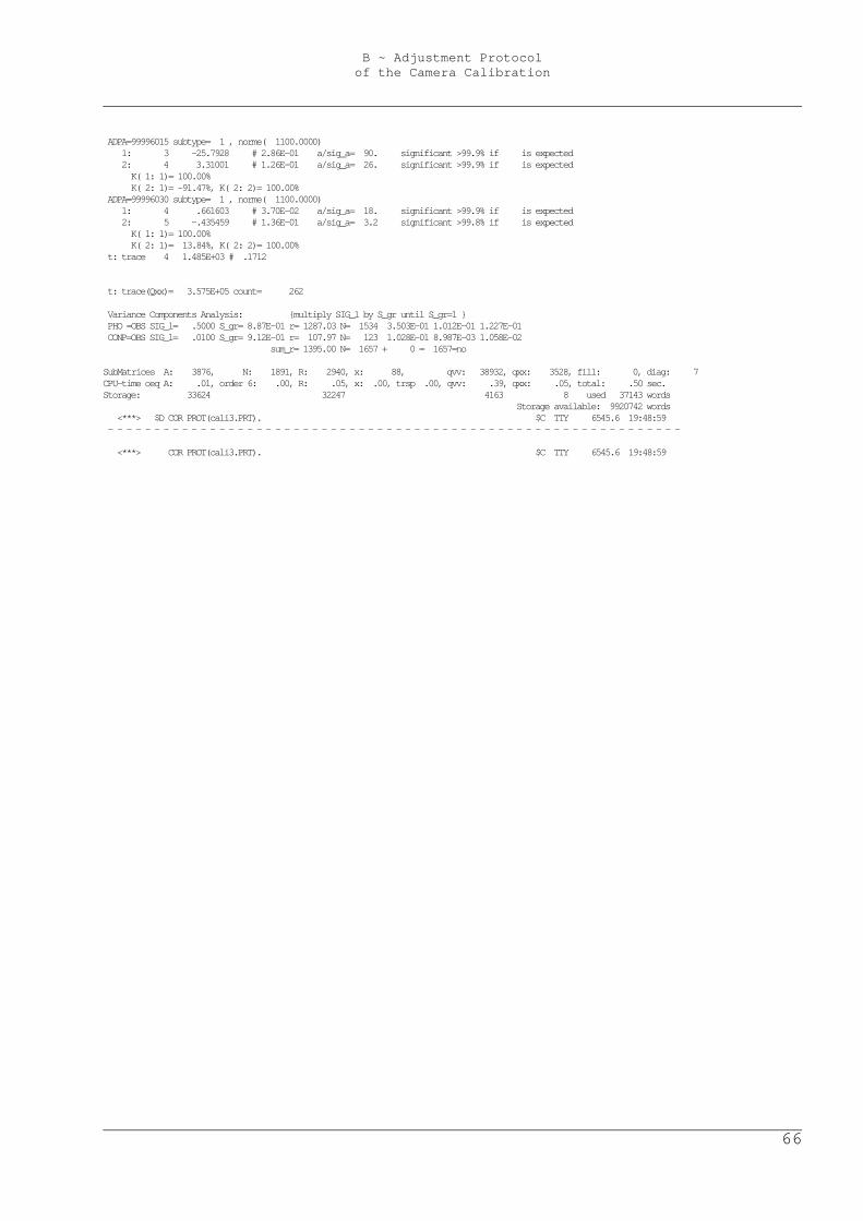
B ~ Adjustment Protocol of the Camera Calibration
66
ADPA=99996015 subtype= 1 , norme( 1100.0000) 1: 3 -25.7928 # 2.86E-01 a/sig_a= 90. significant >99.9% if is expected 2: 4 3.31001 # 1.26E-01 a/sig_a= 26. significant >99.9% if is expected K( 1: 1)= 100.00% K( 2: 1)= -91.47%, K( 2: 2)= 100.00% ADPA=99996030 subtype= 1 , norme( 1100.0000) 1: 4 .661603 # 3.70E-02 a/sig_a= 18. significant >99.9% if is expected 2: 5 -.435459 # 1.36E-01 a/sig_a= 3.2 significant >99.8% if is expected K( 1: 1)= 100.00% K( 2: 1)= 13.84%, K( 2: 2)= 100.00% t: trace 4 1.485E+03 # .1712 t: trace(Qxx)= 3.575E+05 count= 262 Variance Components Analysis: {multiply SIG_l by S_gr until S_gr=1 } PHO =OBS SIG_l= .5000 S_gr= 8.87E-01 r= 1287.03 N= 1534 3.503E-01 1.012E-01 1.227E-01 CONP=OBS SIG_l= .0100 S_gr= 9.12E-01 r= 107.97 N= 123 1.028E-01 8.987E-03 1.058E-02 sum_r= 1395.00 N= 1657 + 0 = 1657=no SubMatrices A: 3876, N: 1891, R: 2940, x: 88, qvv: 38932, qxx: 3528, fill: 0, diag: 7 CPU-time oeq A: .01, order 6: .00, R: .05, x: .00, trsp .00, qvv: .39, qxx: .05, total: .50 sec. Storage: 33624 32247 4163 8 used 37143 words Storage available: 9920742 words <***> $D COR PROT(cali3.PRT). $C TTY 6545.6 19:48:59 - - - - - - - - - - - - - - - - - - - - - - - - - - - - - - - - - - - - - - - - - - - - - - - - - - - - - - - - - - - - - - <***> COR PROT(cali3.PRT). $C TTY 6545.6 19:48:59
C ~ Stability of the Camera’s Interior Orientation
67
C Stability of the Camera’s Interior Orientation
Tests on the stability of the used camera’s interior orientation. The question is, whether the coordinates of the principal point x0 and y0 and the focal length c for the camera setting of 15mm focal length differ significantly before and after an alteration of the focal length to 30mm. Therefore, two interior orientations for the camera setting of 15mm focal length are presumed, one for the set of 15mm-photos taken before the alteration, the other one for the 15mm-set taken afterwards. The two interior orientations must be calculated in two adjustments that are statistically independent from each other, i.e. observations used in the first adjustment shall not be utilized in the second one. The used pass-points are observed quantities that are needed in both calculations and hence produce unwanted correlations. To avoid this, their standard deviations are set to a minimum, which means that they are treated as quasi-fix points. As the additional lens distortion parameters are not analysed, neither they are adjusted.
C.1 Adjustment Protocol of the First Set of 15mm-Photos
ORIENT adjustment protocol of the first set of 10 photos with a focal length of 15mm, cf. chapter 2.3. < File FIRSTSET15MM.PRT opened FORMATTE UNKNOWN SEQUENTI > F PROJECT(cali3 ) USER(wuen ) 04Feb-04 01:59:59 <1040> D60 Calibration directory: 15 entries used, 85 available; core_memory: 4883 words used, 9995115 available. REFSYS.000 refrak=0 curvat=0 {-1.0191E-08 6378000.0} units 1.E+00[m] REF 9001.000: 53/ 57, 0 !!! REF 9001.000: average discrepancies before adjustment 704, CATEGORY 1 Observation :ukn :#all-#mk:used co:sum_res robfac _resres, resmax _ nammax # sigma erp/prc rotpar ior/sca adp .sub ShowMARKed point ( dx dy dz ) weights index PHO 2210:OPRI. 41 : 41 x: -.017 1.476 .267 .738 43 individ. 90002210 2210 99996015 99996015 .002
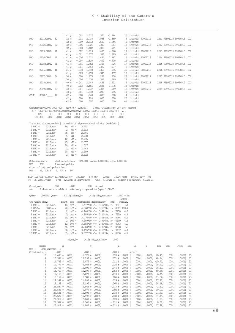
C ~ Stability of the Camera’s Interior Orientation
68
: 41 y: .002 2.527 .374 -1.264 20 individ. PHO 2211:OPRI. 32 : 32 x: .031 2.738 .538 -1.369 5 individ. 90002211 2211 99996015 99996015 .002 : 32 y: -.019 2.912 .512 1.456 2 individ. PHO 2212:OPRI. 32 : 32 x: -.005 1.321 .312 -.661 17 individ. 90002212 2212 99996015 99996015 .002 : 32 y: -.003 1.482 .379 -.741 7 individ. PHO 2213:OPRI. 41 : 41 x: .012 1.719 .403 -.860 19 individ. 90002213 2213 99996015 99996015 .002 : 41 y: -.011 2.577 .393 1.289 45 individ. PHO 2214:OPRI. 41 : 41 x: -.026 2.322 .484 1.161 2 individ. 90002214 2214 99996015 99996015 .002 : 41 y: -.008 1.810 .402 -.905 15 individ. PHO 2215:OPRI. 41 : 41 x: -.001 1.452 .343 .726 17 individ. 90002215 2215 99996015 99996015 .002 : 41 y: -.011 1.554 .327 .777 8 individ. PHO 2216:OPRI. 41 : 41 x: .033 1.910 .358 -.955 45 individ. 90002216 2216 99996015 99996015 .002 : 41 y: .009 1.474 .345 .737 10 individ. PHO 2217:OPRI. 34 : 34 x: .010 1.675 .288 .838 23 individ. 90002217 2217 99996015 99996015 .002 : 34 y: .016 1.738 .358 .869 29 individ. PHO 2218:OPRI. 40 : 40 x: -.041 2.443 .431 1.221 2 individ. 90002218 2218 99996015 99996015 .002 : 40 y: .013 3.551 .553 -1.775 16 individ. PHO 2219:OPRI. 33 : 33 x: .014 1.837 .395 -.919 12 individ. 90002219 2219 99996015 99996015 .002 : 33 y: .011 1.510 .283 .755 17 individ. CONP 8888:O____ 42 : 42 x: .000 .048 .000 .000 4 individ. : 42 y: .000 .124 .000 .000 20 individ. : 42 z: .000 .057 .000 .000 41 individ. WEIGHTFU(1000.000 1000.000), MARK d > 1.0E+31: 0 obs. OMCATEG(x:8 y:7 z:6) marked d * 200.00|400.00|600.00|800.001000.0 1200.0 1400.0 1600.0 1800.0 | ... | 878 | 0 | 0 | 0 | 0 | 0 | 0 | 0 | 0 | 0 | 100.00%| .00%| .00%| .00%| .00%| .00%| .00%| .00%| .00%| .00%| The worst discrepancies [ in units of sigma-a-priori of obs.(=robfac) ]: 1 PHO = 2218,nr= 16, dY = 3.551 2 PHO = 2211,nr= 2, dY = 2.912 3 PHO = 2211,nr= 35, dY = 2.866 4 PHO = 2211,nr= 5, dX = 2.738 5 PHO = 2218,nr= 12, dY = 2.735 6 PHO = 2213,nr= 45, dY = 2.577 7 PHO = 2210,nr= 20, dY = 2.527 8 PHO = 2218,nr= 2, dX = 2.443 9 PHO = 2211,nr= 35, dX = 2.399 10 PHO = 2214,nr= 2, dX = 2.322 Solutiontime = .063 sec.,trace= 689.000, swei= 1.00E+06, eps= 1.00E-06 REF 9001 : 1 unused points Count of computed points in: REF : 52, IOR : 1, ROT : 10 pll= 1.1719E+02,pvv= 1.1719E+02,nx= 189,no= 878,nt= 0,oeq: 14936,neq: 14457, adj= 704 IT= -2, s(pll/nobs= 878)= 3.6535E-01 s(pvv/nred= 689)= 4.1242E-01 =sigma0 ; S_apriori= 5.00E-01 Coord_red: .000 .000 .000 stored --> 3 observations without redundancy compared to Qeps= 1.0E-05. Qmin= .00030, Qmax= .97119; Sigma_0= .412; Sig_apriori= .500 = Sa inner_ The worst obs.: point, coo normalized_discrepancy r(i) reliab. 1 PHO = 2218,nr= 16, qvY = 4.447*S0 =̂ = 3.67*Sa, r= .9374, 4.1 2 CONP= 8888,nr= 20, qvY = 4.360*S0 =̂ = 3.60*Sa, r= .0011,118.4 3 PHO = 2211,nr= 2, qvY = 4.140*S0 =̂ = 3.42*Sa, r= .7270, 4.7 4 PHO = 2211,nr= 5, qvX = 3.805*S0 =̂ = 3.14*Sa, r= .7609, 4.6 5 PHO = 2211,nr= 35, qvY = 3.776*S0 =̂ = 3.11*Sa, r= .8464, 4.3 6 PHO = 2218,nr= 2, qvX = 3.589*S0 =̂ = 2.96*Sa, r= .6809, 4.8 7 PHO = 2218,nr= 12, qvY = 3.503*S0 =̂ = 2.89*Sa, r= .8963, 4.2 8 PHO = 2213,nr= 45, qvY = 3.383*S0 =̂ = 2.79*Sa, r= .8528, 4.3 9 PHO = 2210,nr= 20, qvY = 3.155*S0 =̂ = 2.60*Sa, r= .9437, 4.1 10 PHO = 2211,nr= 35, qvX = 3.077*S0 =̂ = 2.54*Sa, r= .8930, 4.2 Sigma_0= .412; Sig_apriori= .500 point X Y Z A B phi Pxy Pxyz Equ REF = 9001 subtype= 0 Coord_reduc.: .000 # , .000 # , .000 # stored 2 10.403 # .0001, 6.978 # .0001, .020 # .0001 ( .0001, .0001, 20.49, .0001, .0001) 19 4 10.394 # .0001, 15.197 # .0001, .071 # .0001 ( .0001, .0001, 68.14, .0001, .0001) 17 5 14.783 # .0001, 2.875 # .0001, .021 # .0001 ( .0001, .0001, -15.72, .0001, .0001) 23 6 14.772 # .0001, 6.983 # .0001, .026 # .0001 ( .0001, .0001, 15.43, .0001, .0001) 23 7 14.766 # .0001, 11.096 # .0001, .044 # .0001 ( .0001, .0001, 38.13, .0001, .0001) 23 8 14.767 # .0001, 15.197 # .0001, .053 # .0001 ( .0001, .0001, 50.69, .0001, .0001) 23 9 19.165 # .0001, 2.874 # .0001, -.010 # .0001 ( .0001, .0001, -6.45, .0001, .0001) 23 10 19.152 # .0001, 6.981 # .0001, .006 # .0001 ( .0001, .0001, 11.56, .0001, .0001) 23 11 19.149 # .0001, 11.097 # .0001, .029 # .0001 ( .0001, .0001, 27.22, .0001, .0001) 23 12 19.139 # .0001, 15.195 # .0001, .060 # .0001 ( .0001, .0001, 38.48, .0001, .0001) 23 13 23.537 # .0001, 2.868 # .0001, -.017 # .0001 ( .0001, .0001, -2.60, .0001, .0001) 23 14 23.538 # .0001, 6.979 # .0001, .002 # .0001 ( .0001, .0001, 10.01, .0001, .0001) 23 15 23.531 # .0001, 11.094 # .0001, .010 # .0001 ( .0001, .0001, 21.52, .0001, .0001) 23 16 23.527 # .0001, 15.192 # .0001, .030 # .0001 ( .0001, .0001, 31.11, .0001, .0001) 23 17 27.912 # .0001, 2.867 # .0001, -.028 # .0001 ( .0001, .0001, -1.27, .0001, .0001) 23 18 27.902 # .0001, 6.966 # .0001, -.011 # .0001 ( .0001, .0001, 8.68, .0001, .0001) 23 19 27.912 # .0001, 11.082 # .0001, -.011 # .0001 ( .0001, .0001, 17.98, .0001, .0001) 23
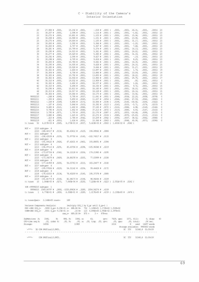
C ~ Stability of the Camera’s Interior Orientation
69
20 27.908 # .0001, 15.192 # .0001, -.018 # .0001 ( .0001, .0001, 26.31, .0001, .0001) 23 21 30.257 # .0001, 2.596 # .0001, 1.116 # .0001 ( .0001, .0001, -1.82, .0001, .0001) 23 23 30.272 # .0001, 10.801 # .0001, 1.103 # .0001 ( .0001, .0001, 15.96, .0001, .0001) 23 24 30.258 # .0001, 14.908 # .0001, 1.101 # .0001 ( .0001, .0001, 23.90, .0001, .0001) 23 25 30.270 # .0001, 19.004 # .0001, 1.105 # .0001 ( .0001, .0001, 31.17, .0001, .0001) 23 26 30.283 # .0001, 2.592 # .0001, 5.366 # .0001 ( .0001, .0001, -1.20, .0001, .0001) 23 27 30.283 # .0001, 6.707 # .0001, 5.367 # .0001 ( .0001, .0001, 7.68, .0001, .0001) 23 28 30.281 # .0001, 10.799 # .0001, 5.374 # .0001 ( .0001, .0001, 16.13, .0001, .0001) 23 29 30.290 # .0001, 14.915 # .0001, 5.361 # .0001 ( .0001, .0001, 24.02, .0001, .0001) 23 30 30.277 # .0001, 19.029 # .0001, 5.365 # .0001 ( .0001, .0001, 31.33, .0001, .0001) 23 31 30.292 # .0001, 2.590 # .0001, 9.627 # .0001 ( .0001, .0001, -.19, .0001, .0001) 23 32 30.298 # .0001, 6.705 # .0001, 9.618 # .0001 ( .0001, .0001, 8.25, .0001, .0001) 23 33 30.283 # .0001, 10.784 # .0001, 9.642 # .0001 ( .0001, .0001, 16.35, .0001, .0001) 23 34 30.295 # .0001, 14.935 # .0001, 9.628 # .0001 ( .0001, .0001, 24.10, .0001, .0001) 23 35 30.285 # .0001, 19.028 # .0001, 9.644 # .0001 ( .0001, .0001, 31.27, .0001, .0001) 23 36 30.302 # .0001, 2.604 # .0001, 13.897 # .0001 ( .0001, .0001, 1.74, .0001, .0001) 19 37 30.304 # .0001, 6.708 # .0001, 13.886 # .0001 ( .0001, .0001, 10.09, .0001, .0001) 19 38 30.305 # .0001, 10.792 # .0001, 13.893 # .0001 ( .0001, .0001, 18.22, .0001, .0001) 19 39 30.302 # .0001, 14.934 # .0001, 13.900 # .0001 ( .0001, .0001, 25.75, .0001, .0001) 17 40 30.310 # .0001, 19.032 # .0001, 13.909 # .0001 ( .0001, .0001, .00, .0001, .0001) 3 41 30.322 # .0001, 2.602 # .0001, 18.157 # .0001 ( .0001, .0001, 1.26, .0001, .0001) 15 42 30.310 # .0001, 6.694 # .0001, 18.150 # .0001 ( .0001, .0001, 9.72, .0001, .0001) 15 43 30.296 # .0001, 10.812 # .0001, 18.160 # .0001 ( .0001, .0001, 18.10, .0001, .0001) 15 44 30.313 # .0001, 14.917 # .0001, 18.169 # .0001 ( .0001, .0001, 26.16, .0001, .0001) 15 45 30.304 # .0001, 19.040 # .0001, 18.175 # .0001 ( .0001, .0001, 33.92, .0001, .0001) 15 90002210 -.268 # .0045, 5.795 # .0037, 11.041 # .0051 ( .0046, .0036, 22.20, .0058, .0078) 0 90002211 -.350 # .0043, 5.850 # .0045, 11.227 # .0054 ( .0046, .0042, 67.59, .0062, .0082) 0 90002212 -.169 # .0189, 5.806 # .0172, 33.444 # .0196 ( .0195, .0165, -30.92, .0256, .0322) 0 90002213 -.187 # .0143, 5.846 # .0103, 33.392 # .0123 ( .0143, .0103, -5.71, .0176, .0215) 0 90002214 9.685 # .0121, 1.602 # .0086, 37.165 # .0072 ( .0122, .0086, 4.98, .0149, .0166) 0 90002215 9.790 # .0119, 1.452 # .0086, 37.213 # .0072 ( .0119, .0085, 4.93, .0147, .0163) 0 90002216 3.795 # .0071, 1.793 # .0055, 22.176 # .0087 ( .0072, .0053, -16.68, .0090, .0125) 0 90002217 3.880 # .0083, 1.625 # .0072, 22.272 # .0104 ( .0085, .0070, -25.83, .0110, .0152) 0 90002218 .323 # .0046, 1.786 # .0042, 10.209 # .0062 ( .0050, .0037, 38.52, .0062, .0088) 0 90002219 .421 # .0053, 1.636 # .0051, 10.366 # .0063 ( .0055, .0048, 40.90, .0073, .0096) 0 t: trace 52 6.217E-03 # .0045, 4.173E-03 # .0037, 5.623E-03 # .0043 ( 1.601E-02 # .0042 ) ROT = 2210 subtype= 4 2210 -188.42117 # .0132, 85.63412 # .0129, 194.49062 # .0084 ROT = 2211 subtype= 4 2211 -196.43539 # .0155, 72.97750 # .0145, -102.74517 # .0133 ROT = 2212 subtype= 4 2212 -191.59122 # .0426, 47.42631 # .0402, 193.88051 # .0394 ROT = 2213 subtype= 4 2213 -194.97113 # .0291, 45.43706 # .0298, -105.96348 # .0219 ROT = 2214 subtype= 4 2214 -173.87724 # .0362, 34.12128 # .0206, 179.21985 # .0295 ROT = 2215 subtype= 4 2215 -173.39279 # .0409, 28.86378 # .0205, 77.03999 # .0338 ROT = 2216 subtype= 4 2216 -177.41959 # .0200, 56.03763 # .0210, 183.24477 # .0140 ROT = 2217 subtype= 4 2217 -195.57834 # .0220, 54.31142 # .0254, 99.46428 # .0172 ROT = 2218 subtype= 4 2218 -178.63315 # .0136, 78.43259 # .0145, 195.37378 # .0085 ROT = 2219 subtype= 4 2219 -191.81773 # .0140, 82.48173 # .0158, 98.94244 # .0109 t: trace 10 1.064E-05 # .0271, 7.645E-06 # .0230, 7.226E-06 # .0223 ( 2.551E-05 # .0242 ) IOR =99996015 subtype= 1 99996015 1549.04797 # .2850, -1035.89636 # .3289, 2054.56274 # .4159 t: trace 1 4.776E-01 # .2850, 6.358E-01 # .3289, 1.017E+00 # .4159 ( 2.130E+00 # .3476 ) t: trace(Qxx)= 2.146E+00 count= 189 Variance Components Analysis: {multiply SIG_l by S_gr until S_gr=1 } PHO =OBS SIG_l= .5000 S_gr= 8.25E-01 r= 688.86 N= 752 1.145E+01 1.172E+02 1.310E+02 CONP=OBS SIG_l= .0001 S_gr= 9.15E-01 r= .14 N= 123 4.896E+00 2.956E-02 2.397E+01 sum_r= 689.00 N= 875 + 3 = 878=no SubMatrices A: 1546, N: 886, R: 1066, x: 63, qvv: 7629, qxx: 1071, fill: 0, diag: 43 CPU-time oeq A: .02, order 6: .00, R: .00, x: .00, trsp .00, qvv: .05, qxx: .00, total: .06 sec. Storage: 14936 11989 2216 8 used 14457 words Storage available: 9965663 words <***> $D COR PROT(cali3.PRT). $C TTY 51540.8 01:59:59 - - - - - - - - - - - - - - - - - - - - - - - - - - - - - - - - - - - - - - - - - - - - - - - - - - - - - - - - - - - - - - <***> COR PROT(cali3.PRT). $C TTY 51540.8 01:59:59
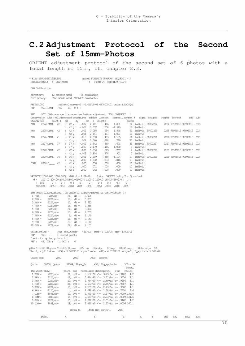
C ~ Stability of the Camera’s Interior Orientation
70
C.2 Adjustment Protocol of the Second Set of 15mm-Photos
ORIENT adjustment protocol of the second set of 6 photos with a focal length of 15mm, cf. chapter 2.3. < File SECONDSET15MM.PRT opened FORMATTE UNKNOWN SEQUENTI > F PROJECT(cali3 ) USER(wuen ) 04Feb-04 02:04:39 <1034> D60 Calibration directory: 12 entries used, 88 available; core_memory: 3559 words used, 9996439 available. REFSYS.000 refrak=0 curvat=0 {-1.0191E-08 6378000.0} units 1.E+00[m] REF 9001.000: 49/ 53, 0 !!! REF 9001.000: average discrepancies before adjustment 706, CATEGORY 1 Observation :ukn :#all-#mk:used co:sum_res robfac _resres, resmax _ nammax # sigma erp/prc rotpar ior/sca adp .sub ShowMARKed point ( dx dy dz ) weights index PHO 2224:OPRI. 42 : 42 x: -.002 2.101 .416 1.051 24 individ. 90002224 2224 99996015 99996015 .002 : 42 y: -.006 3.037 .638 -1.519 18 individ. PHO 2225:OPRI. 42 : 42 x: .002 3.095 .554 1.548 21 individ. 90002225 2225 99996015 99996015 .002 : 42 y: -.004 2.141 .481 1.071 11 individ. PHO 2226:OPRI. 41 : 41 x: .010 2.370 .403 1.185 26 individ. 90002226 2226 99996015 99996015 .002 : 41 y: .004 1.560 .388 .780 21 individ. PHO 2227:OPRI. 37 : 37 x: -.002 1.342 .360 .671 35 individ. 90002227 2227 99996015 99996015 .002 : 37 y: .009 2.179 .446 1.090 9 individ. PHO 2228:OPRI. 42 : 42 x: -.006 1.534 .369 -.767 2 individ. 90002228 2228 99996015 99996015 .002 : 42 y: -.003 1.804 .378 .902 5 individ. PHO 2229:OPRI. 36 : 36 x: -.001 2.209 .358 -1.104 17 individ. 90002229 2229 99996015 99996015 .002 : 36 y: .000 1.632 .333 .816 17 individ. CONP 8888:O____ 42 : 42 x: .000 .038 .000 .000 10 individ. : 42 y: .000 .072 .000 .000 10 individ. : 42 z: .000 .042 .000 .000 12 individ. WEIGHTFU(1000.000 1000.000), MARK d > 1.0E+31: 0 obs. OMCATEG(x:8 y:7 z:6) marked d * 200.00|400.00|600.00|800.001000.0 1200.0 1400.0 1600.0 1800.0 | ... | 606 | 0 | 0 | 0 | 0 | 0 | 0 | 0 | 0 | 0 | 100.00%| .00%| .00%| .00%| .00%| .00%| .00%| .00%| .00%| .00%| The worst discrepancies [ in units of sigma-a-priori of obs.(=robfac) ]: 1 PHO = 2225,nr= 21, dX = 3.095 2 PHO = 2224,nr= 18, dY = 3.037 3 PHO = 2224,nr= 10, dY = 2.633 4 PHO = 2224,nr= 15, dY = 2.388 5 PHO = 2226,nr= 26, dX = 2.370 6 PHO = 2229,nr= 17, dX = 2.209 7 PHO = 2227,nr= 9, dY = 2.179 8 PHO = 2225,nr= 11, dY = 2.141 9 PHO = 2225,nr= 20, dX = 2.110 10 PHO = 2224,nr= 24, dX = 2.101 Solutiontime = .016 sec.,trace= 441.000, swei= 1.00E+06, eps= 1.00E-06 REF 9001 : 1 unused points Count of computed points in: REF : 48, IOR : 1, ROT : 6 pll= 9.2339E+01,pvv= 9.2338E+01,nx= 165,no= 606,nt= 0,oeq: 10032,neq: 9136, adj= 706 IT= -2, s(pll/nobs= 606)= 3.9035E-01 s(pvv/nred= 441)= 4.5759E-01 =sigma0 ; S_apriori= 5.00E-01 Coord_red: .000 .000 .000 stored Qmin= .00008, Qmax= .97004; Sigma_0= .458; Sig_apriori= .500 = Sa inner_ The worst obs.: point, coo normalized_discrepancy r(i) reliab. 1 PHO = 2225,nr= 21, qvX = 3.532*S0 =̂ = 3.23*Sa, r= .9167, 4.2 2 PHO = 2224,nr= 18, qvY = 3.414*S0 =̂ = 3.12*Sa, r= .9454, 4.1 3 PHO = 2224,nr= 10, qvY = 2.944*S0 =̂ = 2.69*Sa, r= .9556, 4.1 4 PHO = 2226,nr= 26, qvX = 2.673*S0 =̂ = 2.45*Sa, r= .9387, 4.1 5 PHO = 2224,nr= 15, qvY = 2.655*S0 =̂ = 2.43*Sa, r= .9662, 4.1 6 PHO = 2225,nr= 4, qvX = 2.599*S0 =̂ = 2.38*Sa, r= .7708, 4.6 7 CONP= 8888,nr= 10, qvY = 2.593*S0 =̂ = 2.37*Sa, r= .0009,131.8 8 CONP= 8888,nr= 15, qvY = 2.551*S0 =̂ = 2.33*Sa, r= .0009,134.5 9 PHO = 2229,nr= 17, qvX = 2.522*S0 =̂ = 2.31*Sa, r= .9162, 4.2 10 CONP= 8888,nr= 18, qvY = 2.461*S0 =̂ = 2.25*Sa, r= .0006,160.1 Sigma_0= .458; Sig_apriori= .500 point X Y Z A B phi Pxy Pxyz Equ
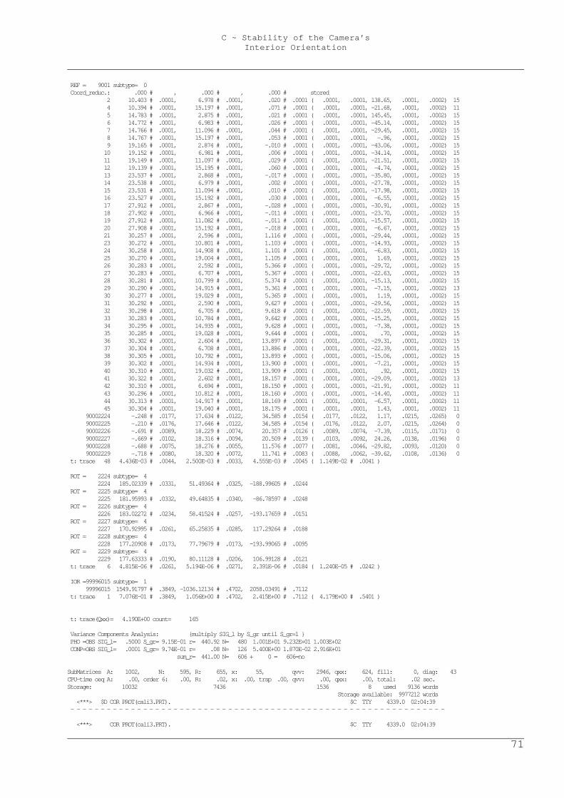
C ~ Stability of the Camera’s Interior Orientation
71
REF = 9001 subtype= 0 Coord_reduc.: .000 # , .000 # , .000 # stored 2 10.403 # .0001, 6.978 # .0001, .020 # .0001 ( .0001, .0001, 138.65, .0001, .0002) 15 4 10.394 # .0001, 15.197 # .0001, .071 # .0001 ( .0001, .0001, -21.68, .0001, .0002) 11 5 14.783 # .0001, 2.875 # .0001, .021 # .0001 ( .0001, .0001, 145.45, .0001, .0002) 15 6 14.772 # .0001, 6.983 # .0001, .026 # .0001 ( .0001, .0001, -45.14, .0001, .0002) 15 7 14.766 # .0001, 11.096 # .0001, .044 # .0001 ( .0001, .0001, -29.45, .0001, .0002) 15 8 14.767 # .0001, 15.197 # .0001, .053 # .0001 ( .0001, .0001, -.96, .0001, .0002) 15 9 19.165 # .0001, 2.874 # .0001, -.010 # .0001 ( .0001, .0001, -43.06, .0001, .0002) 15 10 19.152 # .0001, 6.981 # .0001, .006 # .0001 ( .0001, .0001, -34.14, .0001, .0002) 15 11 19.149 # .0001, 11.097 # .0001, .029 # .0001 ( .0001, .0001, -21.51, .0001, .0002) 15 12 19.139 # .0001, 15.195 # .0001, .060 # .0001 ( .0001, .0001, -4.74, .0001, .0002) 15 13 23.537 # .0001, 2.868 # .0001, -.017 # .0001 ( .0001, .0001, -35.80, .0001, .0002) 15 14 23.538 # .0001, 6.979 # .0001, .002 # .0001 ( .0001, .0001, -27.78, .0001, .0002) 15 15 23.531 # .0001, 11.094 # .0001, .010 # .0001 ( .0001, .0001, -17.98, .0001, .0002) 15 16 23.527 # .0001, 15.192 # .0001, .030 # .0001 ( .0001, .0001, -6.55, .0001, .0002) 15 17 27.912 # .0001, 2.867 # .0001, -.028 # .0001 ( .0001, .0001, -30.91, .0001, .0002) 15 18 27.902 # .0001, 6.966 # .0001, -.011 # .0001 ( .0001, .0001, -23.70, .0001, .0002) 15 19 27.912 # .0001, 11.082 # .0001, -.011 # .0001 ( .0001, .0001, -15.57, .0001, .0002) 15 20 27.908 # .0001, 15.192 # .0001, -.018 # .0001 ( .0001, .0001, -6.67, .0001, .0002) 15 21 30.257 # .0001, 2.596 # .0001, 1.116 # .0001 ( .0001, .0001, -29.44, .0001, .0002) 15 23 30.272 # .0001, 10.801 # .0001, 1.103 # .0001 ( .0001, .0001, -14.93, .0001, .0002) 15 24 30.258 # .0001, 14.908 # .0001, 1.101 # .0001 ( .0001, .0001, -6.83, .0001, .0002) 15 25 30.270 # .0001, 19.004 # .0001, 1.105 # .0001 ( .0001, .0001, 1.69, .0001, .0002) 15 26 30.283 # .0001, 2.592 # .0001, 5.366 # .0001 ( .0001, .0001, -29.72, .0001, .0002) 15 27 30.283 # .0001, 6.707 # .0001, 5.367 # .0001 ( .0001, .0001, -22.63, .0001, .0002) 15 28 30.281 # .0001, 10.799 # .0001, 5.374 # .0001 ( .0001, .0001, -15.13, .0001, .0002) 15 29 30.290 # .0001, 14.915 # .0001, 5.361 # .0001 ( .0001, .0001, -7.15, .0001, .0002) 13 30 30.277 # .0001, 19.029 # .0001, 5.365 # .0001 ( .0001, .0001, 1.19, .0001, .0002) 15 31 30.292 # .0001, 2.590 # .0001, 9.627 # .0001 ( .0001, .0001, -29.56, .0001, .0002) 15 32 30.298 # .0001, 6.705 # .0001, 9.618 # .0001 ( .0001, .0001, -22.59, .0001, .0002) 15 33 30.283 # .0001, 10.784 # .0001, 9.642 # .0001 ( .0001, .0001, -15.25, .0001, .0002) 15 34 30.295 # .0001, 14.935 # .0001, 9.628 # .0001 ( .0001, .0001, -7.38, .0001, .0002) 15 35 30.285 # .0001, 19.028 # .0001, 9.644 # .0001 ( .0001, .0001, .70, .0001, .0002) 15 36 30.302 # .0001, 2.604 # .0001, 13.897 # .0001 ( .0001, .0001, -29.31, .0001, .0002) 15 37 30.304 # .0001, 6.708 # .0001, 13.886 # .0001 ( .0001, .0001, -22.39, .0001, .0002) 15 38 30.305 # .0001, 10.792 # .0001, 13.893 # .0001 ( .0001, .0001, -15.06, .0001, .0002) 15 39 30.302 # .0001, 14.934 # .0001, 13.900 # .0001 ( .0001, .0001, -7.21, .0001, .0002) 15 40 30.310 # .0001, 19.032 # .0001, 13.909 # .0001 ( .0001, .0001, .92, .0001, .0002) 15 41 30.322 # .0001, 2.602 # .0001, 18.157 # .0001 ( .0001, .0001, -29.09, .0001, .0002) 13 42 30.310 # .0001, 6.694 # .0001, 18.150 # .0001 ( .0001, .0001, -21.91, .0001, .0002) 11 43 30.296 # .0001, 10.812 # .0001, 18.160 # .0001 ( .0001, .0001, -14.40, .0001, .0002) 11 44 30.313 # .0001, 14.917 # .0001, 18.169 # .0001 ( .0001, .0001, -6.57, .0001, .0002) 11 45 30.304 # .0001, 19.040 # .0001, 18.175 # .0001 ( .0001, .0001, 1.43, .0001, .0002) 11 90002224 -.248 # .0177, 17.634 # .0122, 34.585 # .0154 ( .0177, .0122, 1.17, .0215, .0265) 0 90002225 -.210 # .0176, 17.646 # .0122, 34.585 # .0154 ( .0176, .0122, 2.07, .0215, .0264) 0 90002226 -.691 # .0089, 18.229 # .0074, 20.357 # .0126 ( .0089, .0074, -7.39, .0115, .0171) 0 90002227 -.669 # .0102, 18.316 # .0094, 20.509 # .0139 ( .0103, .0092, 24.26, .0138, .0196) 0 90002228 -.688 # .0075, 18.276 # .0055, 11.576 # .0077 ( .0081, .0046, -29.82, .0093, .0120) 0 90002229 -.718 # .0080, 18.320 # .0072, 11.741 # .0083 ( .0088, .0062, -39.62, .0108, .0136) 0 t: trace 48 4.436E-03 # .0044, 2.500E-03 # .0033, 4.555E-03 # .0045 ( 1.149E-02 # .0041 ) ROT = 2224 subtype= 4 2224 185.02339 # .0331, 51.49364 # .0325, -188.99605 # .0244 ROT = 2225 subtype= 4 2225 181.95993 # .0332, 49.64835 # .0340, -86.78597 # .0248 ROT = 2226 subtype= 4 2226 183.02272 # .0234, 58.41524 # .0257, -193.17659 # .0151 ROT = 2227 subtype= 4 2227 170.92995 # .0261, 65.25835 # .0285, 117.29264 # .0188 ROT = 2228 subtype= 4 2228 177.20908 # .0173, 77.79679 # .0173, -193.99065 # .0095 ROT = 2229 subtype= 4 2229 177.63333 # .0190, 80.11128 # .0206, 106.99128 # .0121 t: trace 6 4.815E-06 # .0261, 5.194E-06 # .0271, 2.391E-06 # .0184 ( 1.240E-05 # .0242 ) IOR =99996015 subtype= 1 99996015 1549.91797 # .3849, -1036.12134 # .4702, 2058.03491 # .7112 t: trace 1 7.076E-01 # .3849, 1.056E+00 # .4702, 2.415E+00 # .7112 ( 4.179E+00 # .5401 ) t: trace(Qxx)= 4.190E+00 count= 165 Variance Components Analysis: {multiply SIG_l by S_gr until S_gr=1 } PHO =OBS SIG_l= .5000 S_gr= 9.15E-01 r= 440.92 N= 480 1.001E+01 9.232E+01 1.003E+02 CONP=OBS SIG_l= .0001 S_gr= 9.74E-01 r= .08 N= 126 5.400E+00 1.870E-02 2.916E+01 sum_r= 441.00 N= 606 + 0 = 606=no SubMatrices A: 1002, N: 595, R: 655, x: 55, qvv: 2946, qxx: 624, fill: 0, diag: 43 CPU-time oeq A: .00, order 6: .00, R: .02, x: .00, trsp .00, qvv: .00, qxx: .00, total: .02 sec. Storage: 10032 7436 1536 8 used 9136 words Storage available: 9977212 words <***> $D COR PROT(cali3.PRT). $C TTY 4339.0 02:04:39 - - - - - - - - - - - - - - - - - - - - - - - - - - - - - - - - - - - - - - - - - - - - - - - - - - - - - - - - - - - - - - <***> COR PROT(cali3.PRT). $C TTY 4339.0 02:04:39
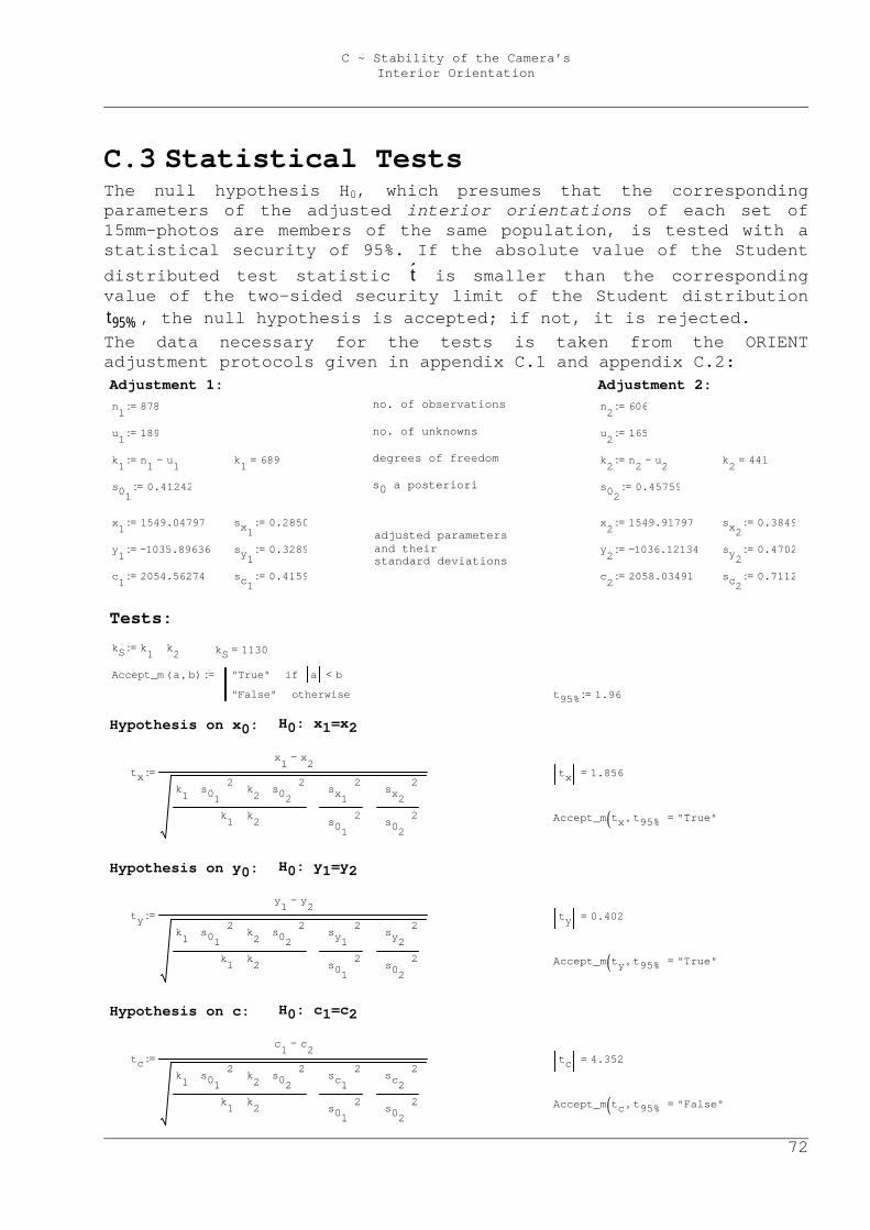
C ~ Stability of the Camera’s Interior Orientation
72
C.3 Statistical Tests The null hypothesis H0, which presumes that the corresponding parameters of the adjusted interior orientations of each set of 15mm-photos are members of the same population, is tested with a statistical security of 95%. If the absolute value of the Student distributed test statistic t̂ is smaller than the corresponding value of the two-sided security limit of the Student distribution
%95t , the null hypothesis is accepted; if not, it is rejected. The data necessary for the tests is taken from the ORIENT adjustment protocols given in appendix C.1 and appendix C.2:
adjusted parameters and their standard deviations
Adjustment 1: Adjustment 2: n1 878:= no. of observations n2 606:=
u1 189:= no. of unknowns u2 165:=
k1 n1 u1−:= k1 689= degrees of freedom k2 n2 u2−:= k2 441=
s010.41242:= s0 a posteriori s02
0.45759:=
x1 1549.04797:= sx10.2850:= x2 1549.91797:= sx2
0.3849:=
y1 1035.89636−:= sy10.3289:= y2 1036.12134−:= sy2
0.4702:=
c1 2054.56274:= sc10.4159:= c2 2058.03491:= sc2
0.7112:=
Tests: kS k1 k2+:= kS 1130= Accept_m a b,( ) "True" a b<if
"False" otherwise
:= t95% 1.96:=
Hypothesis on x0: H0: x1=x2
tx
x1 x2−
k1 s01
2⋅ k2 s02
2⋅+
k1 k2+
sx1
2
s01
2
sx2
2
s02
2
+
⋅
:= tx 1.856=
Accept_m tx t95%,( ) "True"=
Hypothesis on y0: H0: y1=y2
ty
y1 y2−
k1 s01
2⋅ k2 s02
2⋅+
k1 k2+
sy1
2
s01
2
sy2
2
s02
2
+
⋅
:= ty 0.402=
Accept_m ty t95%,( ) "True"=
Hypothesis on c: H0: c1=c2
tc
c1 c2−
k1 s01
2⋅ k2 s02
2⋅+
k1 k2+
sc1
2
s01
2
sc2
2
s02
2
+
⋅
:= tc 4.352=
Accept_m tc t95%,( ) "False"=

C ~ Stability of the Camera’s Interior Orientation
73
The null hypotheses are accepted for the coordinates x0 and y0 of the principal points, but it is rejected for the focal length f, i.e. the focal lengths for the camera setting of 15mm before and after the alteration to 30mm differ significantly, in other words, they do not belong to the same population with a statistical security of 95%.
Bibliography
74
Bibliography [Dorffner, 2002] Dorffner, Lionel: Erzeugung von qualitativ
hochwertigen 3D Photomodellen für internetbasierte Anwendungen mit besonderem Augenmerk auf Objekte der Nahbereichsphotogrammetrie. Dissertation am Institut für Photogrammetrie und Fernerkundung (I.P.F.) der Technischen Universität Wien.
[Kager et al., 2002] Kager, Helmut, Rottensteiner, Franz, Kerschner, Martin, and Stadler, Philipp: ORPHEUS 3.2.1 User manual. Institute of Photogrammetry and Remote sensing, Vienna University of Technology.
[Kager, 2000] Kager, Helmut: Adjustment of algebraic surfaces by least squared distances. International Archives of Photogrammetry and Remote Sensing. Vol. XXXIII, Part B3, Amsterdam.
[Kraus, 1996] Kraus, Karl: Photogrammetrie. Band 2: Verfeinerte Methoden und Anwendungen. Mit Beiträgen von Dr. Josef Jansa und Dr. Helmut Kager. Ferdinand Dümmler’s Verlag, Bonn. Dritte, völlig neue und erweiterte Auflage.
[Reißmann, 1980] Reißmann, Günther: Die Ausgleichungsrechnung. Grundlagen und Anwendungen in der Geodäsie. Verlag für Bauwesen, Berlin.
Bibliography
75
[Rottensteiner, 2001] Rottensteiner, Franz: Halbautomatische Gebäudeexktraktion durch hybride Ausgleichung unter Einbeziehung von 3D Objektmodellen. Eckhardt Seyfert (Hrsg.), 21. Wissenschaftlich-Technische Jahrestagung der DGPF, Konstanz. Publikationen der Deutschen Gesellschaft für Photogrammetrie und Fernerkundung, Band 10.
[VRML97, 1997] The Virtual Reality Modelling Language (VRML) is a file format for describing interactive 3D objects and worlds. VRML is designed to be used on the Internet, intranets, and local client systems. VRML is also intended to be a universal interchange format for integrated 3D graphics and multimedia. VRML may be used in a variety of application areas such as engineering and scientific visualization, multimedia presentations, entertainment and educational titles, web pages, and shared virtual worlds. Cf. http://www.web3d.org/
[VRML97, 2001] The scope of this specification is to cover all forms of access to a VRML browser from external applications. It is equally valid for a database with an object interface to access a standalone browser in a presentation slide as it is for a Java applet operating within a web browser and the available services do not vary.
[Zeisler, 1999] Zeisler, Philipp: Nutzung von VRML für Informationssysteme basierend auf 3D-Photomodellen. Diplomarbeit am Institut für Photogrammetrie und Fernerkundung (I.P.F.) der Technischen Universität Wien.
Acknowledgements
76
Acknowledgements First, I would like to thank my parents who enabled me to study at university and to do my diploma thesis abroad. My stay in Spain was an exciting period of my live. Also, I appreciate having composed my thesis at the I.P.F., above all due to the instructive answers of Dr. Franz Rottensteiner and the critical, demanding questions of Dr. Helmut Kager that likewise helped me a lot to consolidate my studies. Finally, I give big props to many friends of mine who helped me with my work, especially to Miguel CapdeVila Sánchez for assisting me with the geodetic measurements and to my flat mate Andreas Fellner for diverting me with gags when I was stuck in a problem. Stay fresh!
Curriculum vitae
77
Curriculum Vitae Name .................. Wilfried Karel Date of birth ......... Jan 16, 1980 Place of birth ........ Vöcklabruck, OÖ, Austria Education Sep 1986 – Jul 1990 ... Elementary School, Volksschule I, Vöcklabruck Sep 1990 – Jul 1994 ... High School, Bundesgymnasium Vöcklabruck Sep 1994 – Jun 1998 ... High School, Bundesrealgymnasium Vöcklabruck Oct 1998 – Apr 1999 ... Military service Oct 1999 – now ........ Study of Surveying engineering, Vienna University of Technology Feb 2003 – Jul 2003 ... exchange student, Polytechnic University of Valencia, Spain Professional experience Sep 1996 .............. locksmith assistant at Tierkörperverwertung Regau 1996 – now ............ every summer geodetic work at Dipl.-Ing. Friedwin Karel, Vöcklabruck Jul 2000, ............. geodetic work at Jul 2001, Dipl.-Ing. Josef Angst, Vienna Sep 2002; Oct 2001 – Jan 2002, .. teaching tutor for Delphi programming at Oct 2002 – Jan 2003, the Institute of Photogrammetry and Remote Oct 2003 – Jan 2004; Sensing, Vienna University of Technology Dec 2003 – now ........ software developer at the Institute of Photogrammetry and Remote Sensing, Vienna University of Technology
Related Documents