Chapter III Check/Design for AISC-ASD89 This chapter describes the details of the structural steel design and stress check al- gorithms that are used by SAP2000 when the user selects the AISC-ASD89 design code (AISC 1989). Various notations used in this chapter are described in Table III-1. For referring to pertinent sections and equations of the original ASD code, a unique prefix “ASD” is assigned. However, all references to the “Specifications for Allow- able Stress Design of Single-Angle Members” carry the prefix of “ASD SAM”. The design is based on user-specified loading combinations. But the program pro- vides a set of default load combinations that should satisfy requirements for the de- sign of most building type structures. In the evaluation of the axial force/biaxial moment capacity ratios at a station along the length of the member, first the actual member force/moment components and the corresponding capacities are calculated for each load combination. Then the ca- pacity ratios are evaluated at each station under the influence of all load combina- tions using the corresponding equations that are defined in this chapter. The con- trolling capacity ratio is then obtained. A capacity ratio greater than 1.0 indicates overstress. Similarly, a shear capacity ratio is also calculated separately. 15

DesignforAISC-ASD89.pdf
Nov 07, 2014
eer
Welcome message from author
This document is posted to help you gain knowledge. Please leave a comment to let me know what you think about it! Share it to your friends and learn new things together.
Transcript
C h a p t e r III
Check/Design for AISC-ASD89
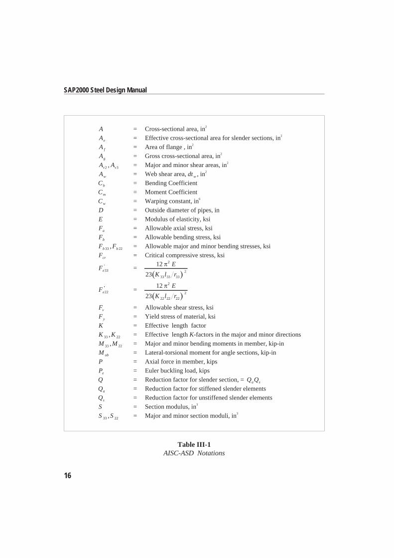
This chapter describes the details of the structural steel design and stress check al-gorithms that are used by SAP2000 when the user selects the AISC-ASD89 designcode (AISC 1989). Various notations used in this chapter are described in TableIII-1.
For referring to pertinent sections and equations of the original ASD code, a uniqueprefix “ASD” is assigned. However, all references to the “Specifications for Allow-able Stress Design of Single-Angle Members” carry the prefix of “ASD SAM”.
The design is based on user-specified loading combinations. But the program pro-vides a set of default load combinations that should satisfy requirements for the de-sign of most building type structures.
In the evaluation of the axial force/biaxial moment capacity ratios at a station alongthe length of the member, first the actual member force/moment components andthe corresponding capacities are calculated for each load combination. Then the ca-pacity ratios are evaluated at each station under the influence of all load combina-tions using the corresponding equations that are defined in this chapter. The con-trolling capacity ratio is then obtained. A capacity ratio greater than 1.0 indicatesoverstress. Similarly, a shear capacity ratio is also calculated separately.
15
16
SAP2000 Steel Design Manual
A = Cross-sectional area, in2
Ae = Effective cross-sectional area for slender sections, in2
A f = Area of flange , in2
Ag = Gross cross-sectional area, in2
A Av v2 3, = Major and minor shear areas, in2
Aw = Web shear area, dtw , in2
Cb = Bending Coefficient
Cm = Moment Coefficient
Cw = Warping constant, in6
D = Outside diameter of pipes, in
E = Modulus of elasticity, ksi
Fa = Allowable axial stress, ksi
Fb = Allowable bending stress, ksi
F Fb b33 22, = Allowable major and minor bending stresses, ksi
Fcr = Critical compressive stress, ksi
Fe33 =12
23
2
33 33 33
2
E
K l r
Fe22 =12
23
2
22 22 22
2
E
K l r
Fv = Allowable shear stress, ksi
Fy = Yield stress of material, ksi
K = Effective length factor
K K33 22, = Effective length K-factors in the major and minor directions
M M33 22, = Major and minor bending moments in member, kip-in
M ob = Lateral-torsional moment for angle sections, kip-in
P = Axial force in member, kips
Pe = Euler buckling load, kips
Q = Reduction factor for slender section, = Q Qa s
Qa = Reduction factor for stiffened slender elements
Qs = Reduction factor for unstiffened slender elements
S = Section modulus, in3
S S33 22, = Major and minor section moduli, in3
Table III-1AISC-ASD Notations
17
Chapter III Check/Design for AISC-ASD89
S Seff eff, ,,33 22 = Effective major and minor section moduli for slender sections, in3
S c = Section modulus for compression in an angle section, in3
V V2 3, = Shear forces in major and minor directions, kips
b = Nominal dimension of plate in a section, inlonger leg of angle sections,b tf w2 for welded and b tf w3 for rolled box sections, etc.
be = Effective width of flange, in
b f = Flange width, in
d = Overall depth of member, in
fa = Axial stress either in compression or in tension, ksi
fb = Normal stress in bending, ksi
f fb b33 22, = Normal stress in major and minor direction bending, ksi
fv = Shear stress, ksi
f fv v2 3, = Shear stress in major and minor direction bending, ksi
h = Clear distance between flanges for I shaped sections ( )d t f2 , in
he = Effective distance between flanges less fillets, in
k = Distance from outer face of flange to web toe of fillet , in
kc = Parameter used for classification of sections,
h tw
if h tw 70 ,
1 if h tw 70 .
l l33 22, = Major and minor direction unbraced member lengths, in
lc = Critical length, in
r = Radius of gyration, in
r r33 22, = Radii of gyration in the major and minor directions, in
rz = Minimum Radius of gyration for angles, in
t = Thickness of a plate in I, box, channel, angle, and T sections, in
t f = Flange thickness, in
t w = Web thickness, in
w = Special section property for angles, in
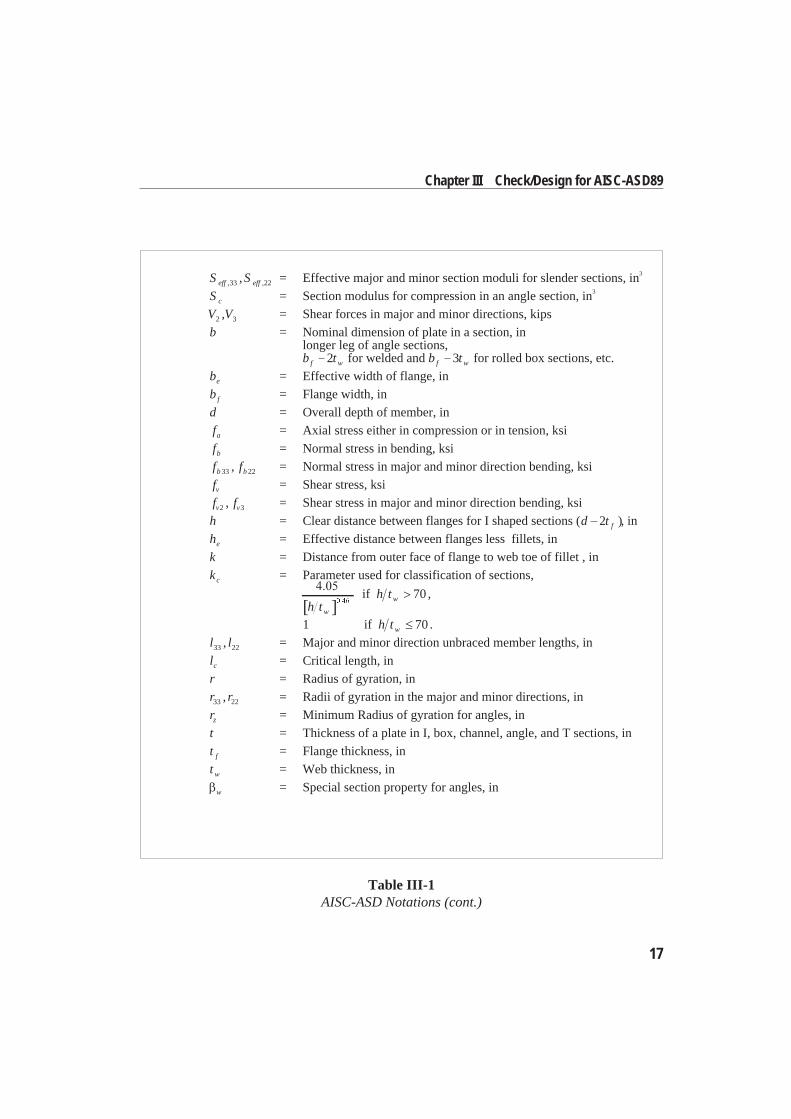
Table III-1AISC-ASD Notations (cont.)
English as well as SI and MKS metric units can be used for input. But the code isbased on Kip-Inch-Second units. For simplicity, all equations and descriptions pre-sented in this chapter correspond to Kip-Inch-Second units unless otherwisenoted.
Design Loading CombinationsThe design load combinations are the various combinations of the load cases forwhich the structure needs to be checked. For the AISC-ASD89 code, if a structure issubjected to dead load (DL), live load (LL), wind load (WL), and earthquake in-duced load (EL), and considering that wind and earthquake forces are reversible,then the following load combinations may have to be defined (ASD A4):
DL (ASD A4.1)DL + LL (ASD A4.1)
DL WL (ASD A4.1)DL + LL WL (ASD A4.1)
DL EL (ASD A4.1)DL + LL EL (ASD A4.1)
These are also the default design load combinations in SAP2000 whenever theAISC-ASD89 code is used. The user should use other appropriate loading combi-nations if roof live load is separately treated, if other types of loads are present, or ifpattern live loads are to be considered.
When designing for combinations involving earthquake and wind loads, allowablestresses are increased by a factor of 4/3 of the regular allowable value (ASD A5.2).
Live load reduction factors can be applied to the member forces of the live load caseon an element-by-element basis to reduce the contribution of the live load to thefactored loading.
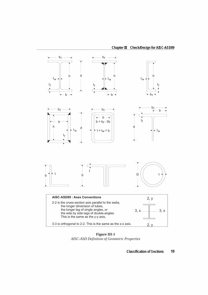
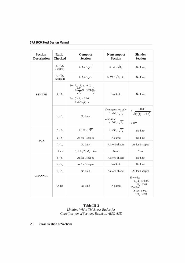
Classification of SectionsThe allowable stresses for axial compression and flexure are dependent upon theclassification of sections as either Compact, Noncompact, Slender, or Too Slender.SAP2000 classifies the individual members according to the limiting width/thick-ness ratios given in Table III-2 (ASD B5.1, F3.1, F5, G1, A-B5-2). The definitionof the section properties required in this table is given in Figure III-1 and TableIII-1.
18 Design Loading Combinations
SAP2000 Steel Design Manual
Classification of Sections 19
Chapter III Check/Design for AISC-ASD89
Figure III-1AISC-ASD Definition of Geometric Properties
20 Classification of Sections
SAP2000 Steel Design Manual
SectionDescription
RatioChecked
CompactSection
NoncompactSection
SlenderSection
I-SHAPE
b tf f2( rolled)
Fy65 Fy95 No limit
b tf f2(welded)
Fy65 F ky c/ No limit
d tw
For f Fa y640
1F
f
Fy
a
y
( ) ,
For f Fa y/257/ Fy .
No limit No limit
h tw No limit
If compression only,Fy253
otherwiseFb760
F Fy y
BOX
b tf Fy190 Fy238 No limit
d tw As for I-shapes No limit No limit
h tw No limit As for I-shapes As for I-shapes
Other t tw f 2 , d bw f None None
CHANNEL
b tf As for I-shapes As for I-shapes No limit
d tw As for I-shapes No limit No limit
h tw No limit As for I-shapes As for I-shapes
Other No limit No limit
If weldedb df w ,t tf w
If rolledb df w ,t tf w
Table III-2Limiting Width-Thickness Ratios for
Classification of Sections Based on AISC-ASD
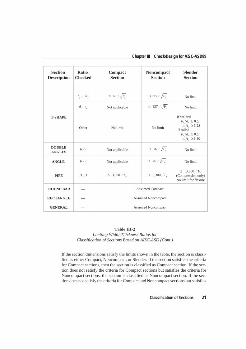
If the section dimensions satisfy the limits shown in the table, the section is classi-fied as either Compact, Noncompact, or Slender. If the section satisfies the criteriafor Compact sections, then the section is classified as Compact section. If the sec-tion does not satisfy the criteria for Compact sections but satisfies the criteria forNoncompact sections, the section is classified as Noncompact section. If the sec-tion does not satisfy the criteria for Compact and Noncompact sections but satisfies
Classification of Sections 21
Chapter III Check/Design for AISC-ASD89
SectionDescription
RatioChecked
CompactSection
NoncompactSection
SlenderSection
T-SHAPE
b tf f2 Fy65 Fy95 No limit
d tw Not applicable Fy127 No limit
Other No limit No limit
If weldedb df w ,t tf w
If rolledb df w ,t tf w
DOUBLEANGLES
b t Not applicable Fy76 No limit
ANGLE b t Not applicable Fy76 No limit
PIPE D t Fy3 300, Fy3 300,Fy
(Compression only)No limit for flexure
ROUND BAR ⎯ Assumed Compact
RECTANGLE ⎯ Assumed Noncompact
GENERAL ⎯ Assumed Noncompact
Table III-2Limiting Width-Thickness Ratios for
Classification of Sections Based on AISC-ASD (Cont.)
the criteria for Slender sections, the section is classified as Slender section. If thelimits for Slender sections are not met, the section is classified as Too Slender.Stress check of Too Slender sections is beyond the scope of SAP2000.
In classifying web slenderness of I-shapes, Box, and Channel sections, it is as-sumed that there are no intermediate stiffeners (ASD F5, G1). Double angles areconservatively assumed to be separated.
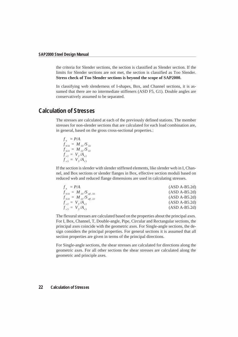
Calculation of StressesThe stresses are calculated at each of the previously defined stations. The memberstresses for non-slender sections that are calculated for each load combination are,in general, based on the gross cross-sectional properties.:
f = P/Aa
f = M /Sb33 33 33
f = M /Sb22 22 22
f = V /Av v2 2 2
f = V /Av v3 3 3
If the section is slender with slender stiffened elements, like slender web in I, Chan-nel, and Box sections or slender flanges in Box, effective section moduli based onreduced web and reduced flange dimensions are used in calculating stresses.
f = P/Aa (ASD A-B5.2d)f = M /Sb eff33 33 33, (ASD A-B5.2d)f = M /Sb eff22 22 22, (ASD A-B5.2d)f = V /Av v2 2 2 (ASD A-B5.2d)f = V /Av v3 3 3 (ASD A-B5.2d)
The flexural stresses are calculated based on the properties about the principal axes.For I, Box, Channel, T, Double-angle, Pipe, Circular and Rectangular sections, theprincipal axes coincide with the geometric axes. For Single-angle sections, the de-sign considers the principal properties. For general sections it is assumed that allsection properties are given in terms of the principal directions.
For Single-angle sections, the shear stresses are calculated for directions along thegeometric axes. For all other sections the shear stresses are calculated along thegeometric and principle axes.
22 Calculation of Stresses
SAP2000 Steel Design Manual
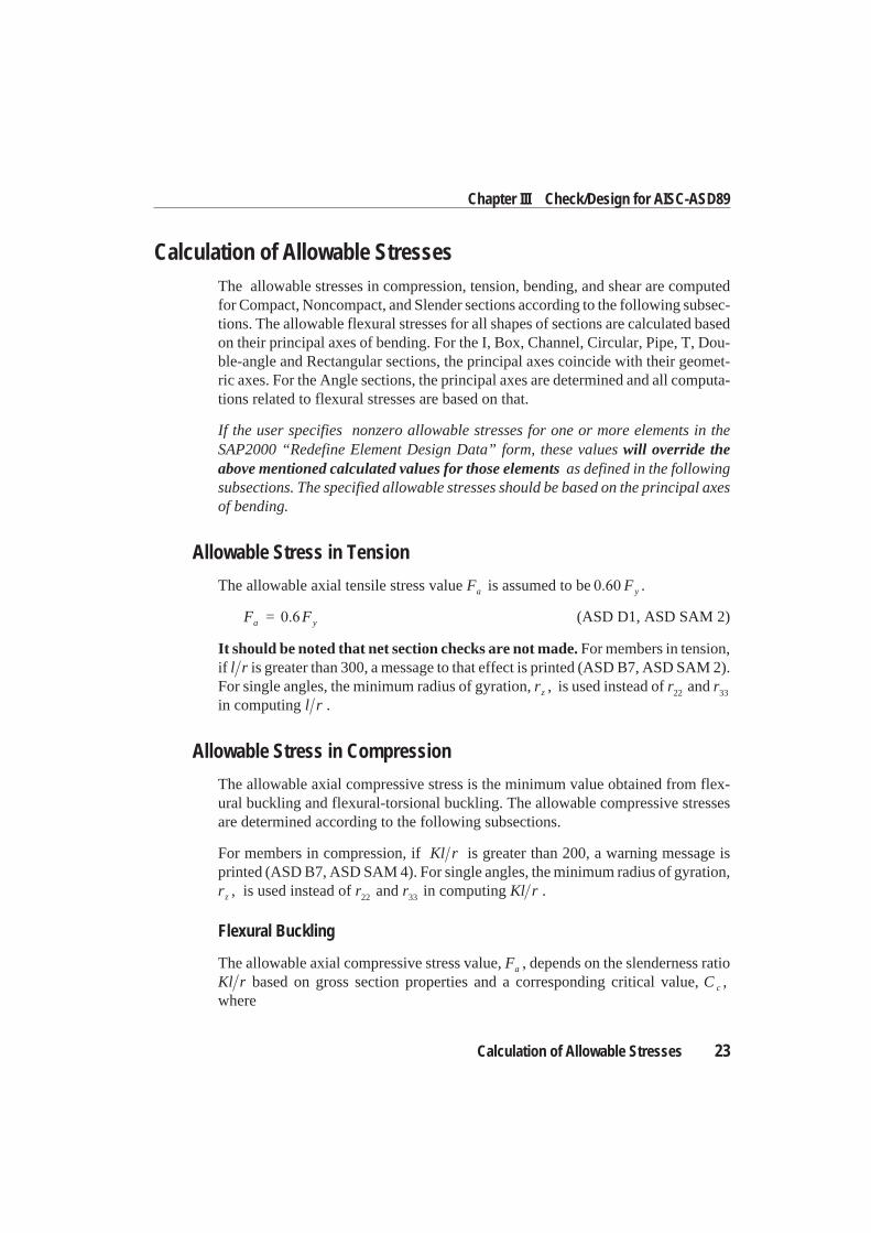
Calculation of Allowable StressesThe allowable stresses in compression, tension, bending, and shear are computedfor Compact, Noncompact, and Slender sections according to the following subsec-tions. The allowable flexural stresses for all shapes of sections are calculated basedon their principal axes of bending. For the I, Box, Channel, Circular, Pipe, T, Dou-ble-angle and Rectangular sections, the principal axes coincide with their geomet-ric axes. For the Angle sections, the principal axes are determined and all computa-tions related to flexural stresses are based on that.
If the user specifies nonzero allowable stresses for one or more elements in theSAP2000 “Redefine Element Design Data” form, these values will override theabove mentioned calculated values for those elements as defined in the followingsubsections. The specified allowable stresses should be based on the principal axesof bending.
Allowable Stress in Tension
The allowable axial tensile stress value Fa is assumed to be Fy .
F = Fa y (ASD D1, ASD SAM 2)
It should be noted that net section checks are not made. For members in tension,if l r is greater than 300, a message to that effect is printed (ASD B7, ASD SAM 2).For single angles, the minimum radius of gyration, rz , is used instead of r22 and r33
in computing l r .
Allowable Stress in Compression
The allowable axial compressive stress is the minimum value obtained from flex-ural buckling and flexural-torsional buckling. The allowable compressive stressesare determined according to the following subsections.
For members in compression, if Kl r is greater than 200, a warning message isprinted (ASD B7, ASD SAM 4). For single angles, the minimum radius of gyration,rz , is used instead of r22 and r33 in computing Kl r .
Flexural Buckling
The allowable axial compressive stress value, Fa , depends on the slenderness ratioKl r based on gross section properties and a corresponding critical value, C c ,where
Calculation of Allowable Stresses 23
Chapter III Check/Design for AISC-ASD89
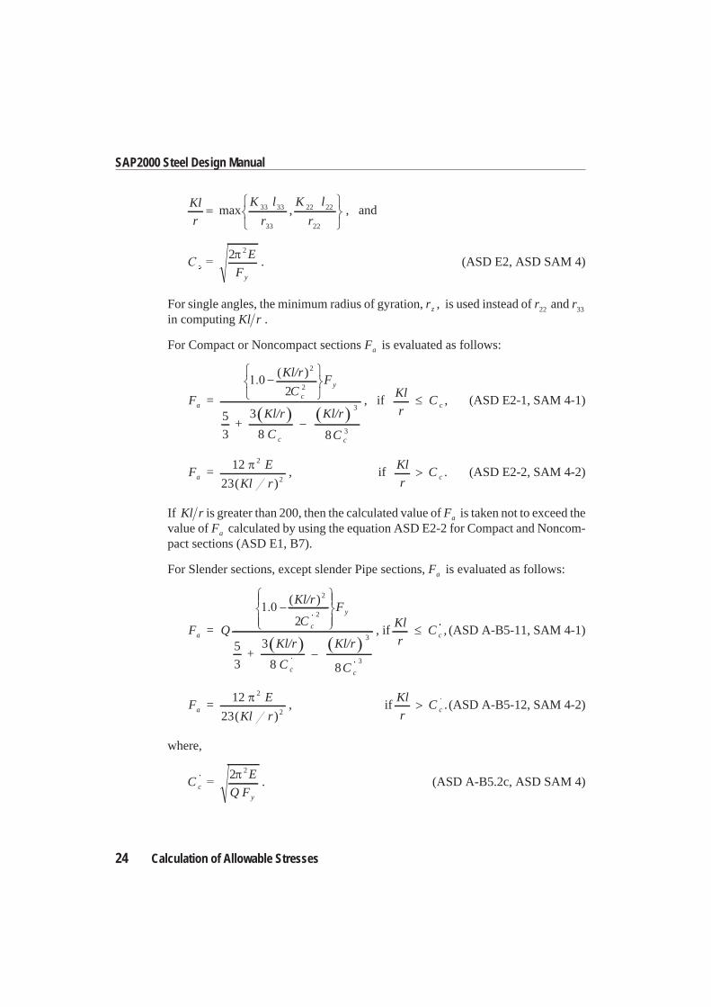
Kl
r
K l
r
K l
rmax ,33 33
33
22 22
22
, and
2 2 E
Fy
. (ASD E2, ASD SAM 4)
For single angles, the minimum radius of gyration, rz , is used instead of r22 and r33
in computing Kl r .
For Compact or Noncompact sections Fa is evaluated as follows:
F =
Kl/r
CF
+Kl/r
C
Ka
c
y
c
( )2
22
5
3
3
8
l/r
C c
3
38
, ifKl
rC c , (ASD E2-1, SAM 4-1)
F =E
Kl ra
12
23
2
2( ), if
Kl
rC c . (ASD E2-2, SAM 4-2)
If Kl r is greater than 200, then the calculated value of Fa is taken not to exceed thevalue of Fa calculated by using the equation ASD E2-2 for Compact and Noncom-pact sections (ASD E1, B7).
For Slender sections, except slender Pipe sections, Fa is evaluated as follows:
F = Q
Kl/r
CF
+Kl/r
C
ac
y
( )2
22
5
3
3
8 c c
Kl/r
C
3
38
, ifKl
rC c , (ASD A-B5-11, SAM 4-1)
F =E
Kl ra
12
23
2
2( ), if
Kl
rC c . (ASD A-B5-12, SAM 4-2)
where,
CE
Q Fc
y
2 2
. (ASD A-B5.2c, ASD SAM 4)
24 Calculation of Allowable Stresses
SAP2000 Steel Design Manual
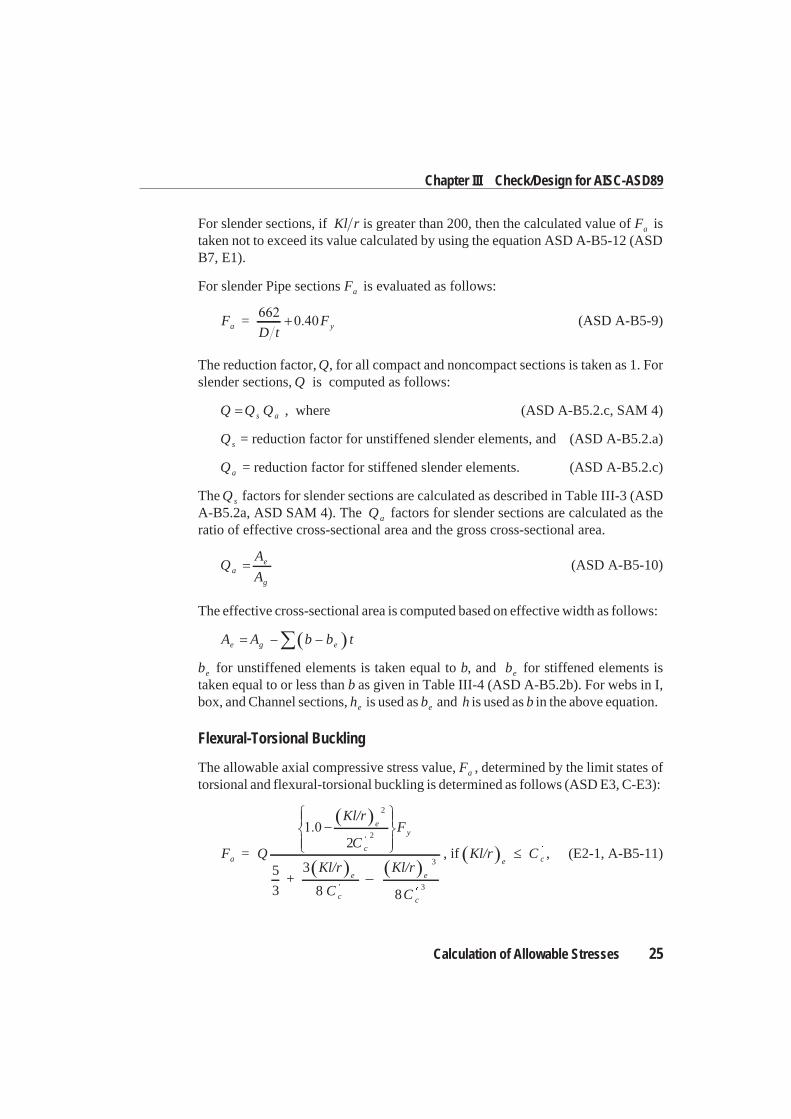
For slender sections, if Kl r is greater than 200, then the calculated value of Fa istaken not to exceed its value calculated by using the equation ASD A-B5-12 (ASDB7, E1).
For slender Pipe sections Fa is evaluated as follows:
F =D t
Fa y (ASD A-B5-9)
The reduction factor, Q, for all compact and noncompact sections is taken as 1. Forslender sections, Q is computed as follows:
Q Q Qs a , where (ASD A-B5.2.c, SAM 4)
Qs = reduction factor for unstiffened slender elements, and (ASD A-B5.2.a)
Qa = reduction factor for stiffened slender elements. (ASD A-B5.2.c)
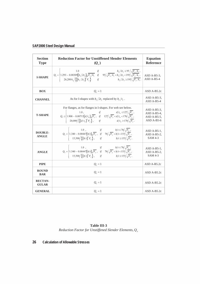
The Qs factors for slender sections are calculated as described in Table III-3 (ASDA-B5.2a, ASD SAM 4). The Qa factors for slender sections are calculated as theratio of effective cross-sectional area and the gross cross-sectional area.
QA
Aa
e
g
(ASD A-B5-10)
The effective cross-sectional area is computed based on effective width as follows:
A A b b te g e
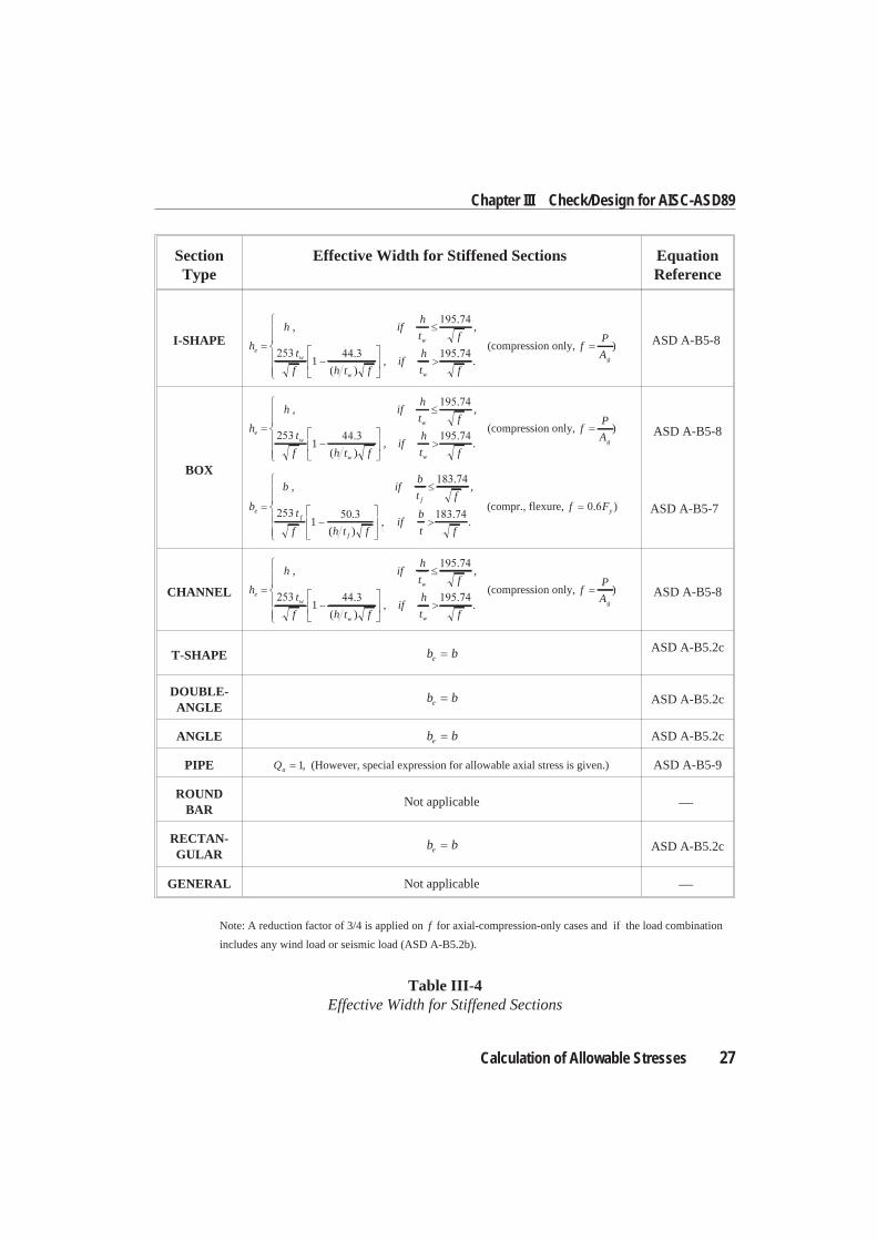
be for unstiffened elements is taken equal to b, and be for stiffened elements istaken equal to or less than b as given in Table III-4 (ASD A-B5.2b). For webs in I,box, and Channel sections, he is used as be and h is used as b in the above equation.
Flexural-Torsional Buckling
The allowable axial compressive stress value, Fa , determined by the limit states oftorsional and flexural-torsional buckling is determined as follows (ASD E3, C-E3):
F = Q
Kl/r
CF
+Kl/r
C
a
e
c
y
e
2
22
5
3
3
8 c
e
c
Kl/r
C
3
38
, if Kl/r Ce c , (E2-1, A-B5-11)
Calculation of Allowable Stresses 25
Chapter III Check/Design for AISC-ASD89
26 Calculation of Allowable Stresses
SAP2000 Steel Design Manual
SectionType
Reduction Factor for Unstiffened Slender Elements(Qs )
EquationReference
I-SHAPEQ
if b t F k
b t F k if Fs
f f y c
f f y c y
2
2
,
k b t F k
k b t F if b t F k
c f f y c
c f f y f f y c
2
2 22
,
.
ASD A-B5-3,ASD A-B5-4
BOX Qs 1 ASD A-B5.2c
CHANNEL As for I-shapes with b tf f2 replaced by b tf f . ASD A-B5-3,ASD A-B5-4
T-SHAPE
For flanges, as for flanges in I-shapes. For web see below.
Q
if d t F
d t F if F d ts
w y
w y y w
,
, F
d t F if d t F
y
w y w y
,
, .2
ASD A-B5-3,ASD A-B5-4,ASD A-B5-5,ASD A-B5-6
DOUBLE-ANGLE
Q
if b t F
b t F if F b ts
y
y y
,
, F
b t F if b t F
y
y y
,
, .2
ASD A-B5-1,ASD A-B5-2,
SAM 4-3
ANGLE Q
if b t F
b t F if F b ts
y
y y
,
, F
b t F if b t F
y
y y
,
, .2
ASD A-B5-1,ASD A-B5-2,
SAM 4-3
PIPE Qs 1 ASD A-B5.2c
ROUNDBAR
Qs 1 ASD A-B5.2c
RECTAN-GULAR
Qs 1 ASD A-B5.2c
GENERAL Qs 1 ASD A-B5.2c
Table III-3Reduction Factor for Unstiffened Slender Elements, Qs
Calculation of Allowable Stresses 27
Chapter III Check/Design for AISC-ASD89
SectionType
Effective Width for Stiffened Sections EquationReference
I-SHAPE h
h ifh
t f
t
f h t fif
h
t
e
w
w
w w
, ,
( ),1
f.
(compression only, fP
Ag
) ASD A-B5-8
BOX
h
h ifh
t f
t
f h t fif
h
t
e
w
w
w w
, ,
( ),1
f.
(compression only, fP
Ag
)
b
b ifb
t f
t
f h t fif
b
t
e
f
f
f
, ,
( ),1
f.
(compr., flexure, f Fy )
ASD A-B5-8
ASD A-B5-7
CHANNEL h
h ifh
t f
t
f h t fif
h
t
e
w
w
w w
, ,
( ),1
f.
(compression only, fP
Ag
) ASD A-B5-8
T-SHAPE b beASD A-B5.2c
DOUBLE-ANGLE
b be ASD A-B5.2c
ANGLE b be ASD A-B5.2c
PIPE Qa 1, (However, special expression for allowable axial stress is given.) ASD A-B5-9
ROUNDBAR
Not applicable ⎯
RECTAN-GULAR
b be ASD A-B5.2c
GENERAL Not applicable ⎯
Note: A reduction factor of 3/4 is applied on f for axial-compression-only cases and if the load combination
includes any wind load or seismic load (ASD A-B5.2b).
Table III-4Effective Width for Stiffened Sections
F =E
Kl/ra
e
12
23
2
2, if Kl/r C
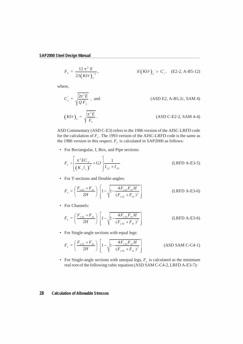
e c . (E2-2, A-B5-12)
where,
CE
Q Fc
y
2 2
, and (ASD E2, A-B5.2c, SAM 4)
Kl/rE
Fee
2
. (ASD C-E2-2, SAM 4-4)
ASD Commentary (ASD C-E3) refers to the 1986 version of the AISC-LRFD codefor the calculation of Fe . The 1993 version of the AISC-LRFD code is the same asthe 1986 version in this respect. Fe is calculated in SAP2000 as follows:
• For Rectangular, I, Box, and Pipe sections:
FEC
K lGJ
I Ie
w
z z
2
222 33
1(LRFD A-E3-5)
• For T-sections and Double-angles:
F =F F
H
F F H
F Fe
e ez e ez
e ez
22 22
2222
1 14
(LRFD A-E3-6)
• For Channels:
F =F F
H
F F H
F Fe
e ez e ez
e ez
33 33
3322
1 14
(LRFD A-E3-6)
• For Single-angle sections with equal legs:
F =F F
H
F F H
F Fe
e ez e ez
e ez
33 33
3322
1 14
(ASD SAM C-C4-1)
• For Single-angle sections with unequal legs, Fe is calculated as the minimumreal root of the following cubic equation (ASD SAM C-C4-2, LRFD A-E3-7):
28 Calculation of Allowable Stresses
SAP2000 Steel Design Manual
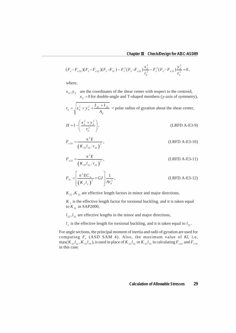
( )( )( ) ( ) (F F F F F F F F Fx
rFe e e e e ez e e e e33 22
222
02
02
2 F Fy
re e 33
02
02
0) ,
where,
x y0 0, are the coordinates of the shear center with respect to the centroid,x 0 0 for double-angle and T-shaped members (y-axis of symmetry),
r x yI I
Ag0 0
202 22 33 = polar radius of gyration about the shear center,
Hx y
r1 0
202
02
, (LRFD A-E3-9)
FE
K l re 33
2
33 33 33
2, (LRFD A-E3-10)
FE
K l re 22
2
22 22 22
2, (LRFD A-E3-11)
FEC
K lGJ
Arez
w
z z
2
202
1, (LRFD A-E3-12)
K K22 33, are effective length factors in minor and major directions,
K z is the effective length factor for torsional buckling, and it is taken equalto K 22 in SAP2000,
l l22 33, are effective lengths in the minor and major directions,
l z is the effective length for torsional buckling, and it is taken equal to l22 .
For angle sections, the principal moment of inertia and radii of gyration are used forcomputing Fe (ASD SAM 4). Also, the maximum value of Kl, i .e,max( , )K l K l22 22 33 33 , is used in place of K l22 22 or K l33 33 in calculating Fe 22 and Fe 33
in this case.
Calculation of Allowable Stresses 29
Chapter III Check/Design for AISC-ASD89
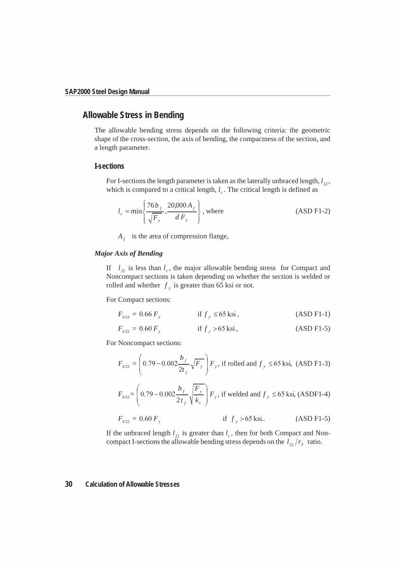
Allowable Stress in Bending
The allowable bending stress depends on the following criteria: the geometricshape of the cross-section, the axis of bending, the compactness of the section, anda length parameter.
I-sections
For I-sections the length parameter is taken as the laterally unbraced length, l22 ,which is compared to a critical length, lc . The critical length is defined as
lb
F
A
d Fc
f
y
f
y
min ,,76 20000
, where (ASD F1-2)
A f is the area of compression flange,
Major Axis of Bending
If l22 is less than lc , the major allowable bending stress for Compact andNoncompact sections is taken depending on whether the section is welded orrolled and whether f y is greater than 65 ksi or not.
For Compact sections:
F = Fb y33 if f y , (ASD F1-1)
F = Fb y33 if f y , (ASD F1-5)
For Noncompact sections:
F =b
tF Fb
f
f
y y33 2, if rolled and f y , (ASD F1-3)
F =b
t
F
kFb
f
f
y
c
y33 2, if welded and f y , (ASDF1-4)
F = Fb y33 if f y .. (ASD F1-5)
If the unbraced length l22 is greater than lc , then for both Compact and Non-compact I-sections the allowable bending stress depends on the l rT22 ratio.
30 Calculation of Allowable Stresses
SAP2000 Steel Design Manual
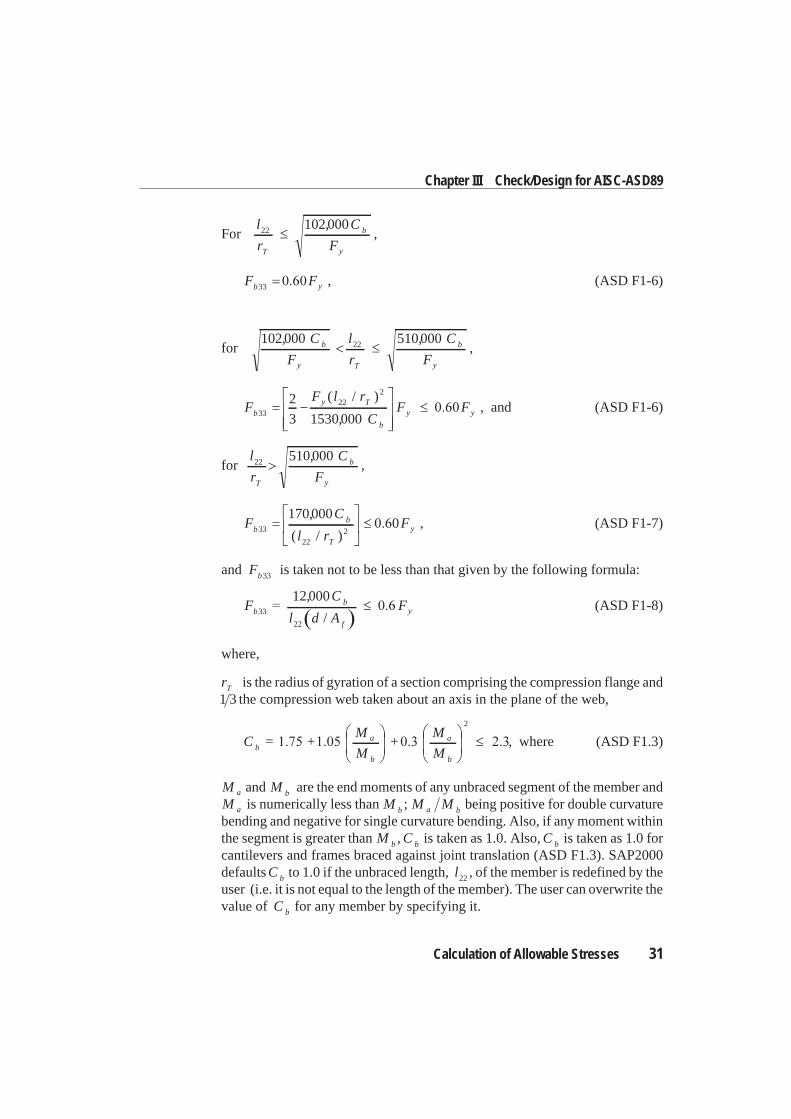
Forl
r
C
FT
b
y
22 102000,,
F Fb y33 , (ASD F1-6)
for102000 51000022, ,C
F
l
r
C
Fb
y T
b
y
,
FF l r
CF Fb
y T
b
y y3322
22
3 1530000
( / )
,, and (ASD F1-6)
forl
r
C
FT
b
y
22 510000,,
FC
l rFb
b
T
y33
222
1700000
,
( / ), (ASD F1-7)
and Fb33 is taken not to be less than that given by the following formula:
FC
l d AFb
b
f
y33
22
12000,
/(ASD F1-8)
where,
rT is the radius of gyration of a section comprising the compression flange and1 3 the compression web taken about an axis in the plane of the web,
C = +M
M+
M
Mba
b
a
b
2
, where (ASD F1.3)
M Ma band are the end moments of any unbraced segment of the member andM a is numerically less than M b ; M Ma b being positive for double curvaturebending and negative for single curvature bending. Also, if any moment withinthe segment is greater than M b , C b is taken as 1.0. Also, C b is taken as 1.0 forcantilevers and frames braced against joint translation (ASD F1.3). SAP2000defaultsC b to 1.0 if the unbraced length, l22 , of the member is redefined by theuser (i.e. it is not equal to the length of the member). The user can overwrite thevalue of C b for any member by specifying it.
Calculation of Allowable Stresses 31
Chapter III Check/Design for AISC-ASD89
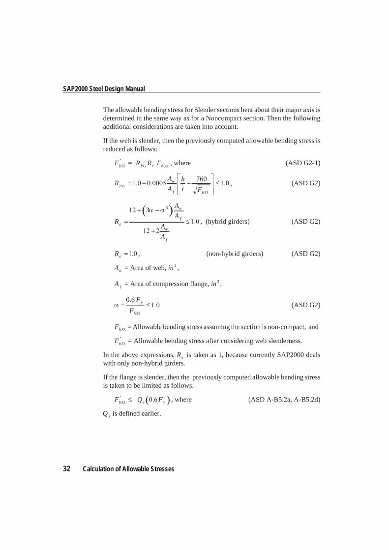
The allowable bending stress for Slender sections bent about their major axis isdetermined in the same way as for a Noncompact section. Then the followingadditional considerations are taken into account.
If the web is slender, then the previously computed allowable bending stress isreduced as follows:
F R R Fb PG e b33 33 , where (ASD G2-1)
RA
A
h
t FPG
w
f b
760
33
, (ASD G2)
R
A
A
A
A
e
w
f
w
f
3 3
, (hybrid girders) (ASD G2)
Re , (non-hybrid girders) (ASD G2)
Aw = Area of web, in 2 ,
A f = Area of compression flange, in 2 ,
F
Fy
b33
(ASD G2)
Fb33 = Allowable bending stress assuming the section is non-compact, and
Fb33 = Allowable bending stress after considering web slenderness.
In the above expressions, Re is taken as 1, because currently SAP2000 dealswith only non-hybrid girders.
If the flange is slender, then the previously computed allowable bending stressis taken to be limited as follows.
F Q Fb s y33 , where (ASD A-B5.2a, A-B5.2d)
Qs is defined earlier.
32 Calculation of Allowable Stresses
SAP2000 Steel Design Manual
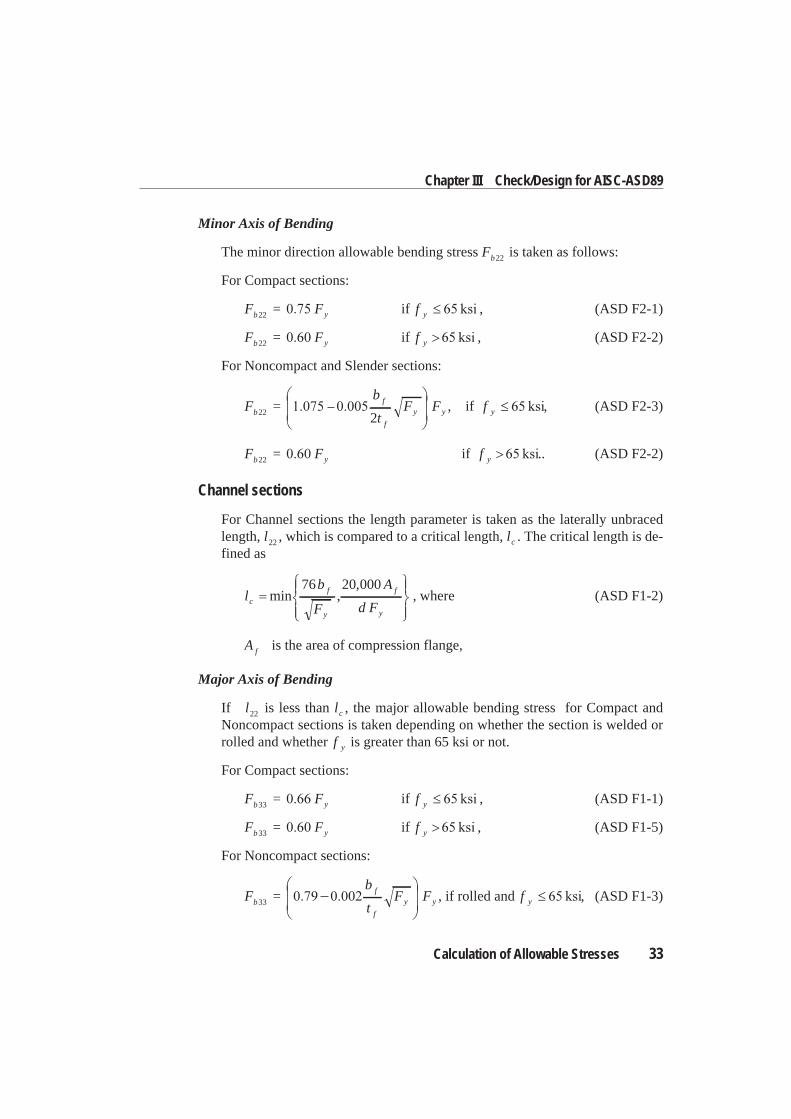
Minor Axis of Bending
The minor direction allowable bending stress Fb22 is taken as follows:
For Compact sections:
F = Fb y22 if f y , (ASD F2-1)
F = Fb y22 if f y , (ASD F2-2)
For Noncompact and Slender sections:
F =b
tF Fb
f
f
y y22 2, if f y , (ASD F2-3)
F = Fb y22 if f y .. (ASD F2-2)
Channel sections
For Channel sections the length parameter is taken as the laterally unbracedlength, l22 , which is compared to a critical length, lc . The critical length is de-fined as
lb
F
A
d Fc
f
y
f
y
min ,,76 20 000
, where (ASD F1-2)
A f is the area of compression flange,
Major Axis of Bending
If l22 is less than lc , the major allowable bending stress for Compact andNoncompact sections is taken depending on whether the section is welded orrolled and whether f y is greater than 65 ksi or not.
For Compact sections:
F = Fb y33 if f y , (ASD F1-1)
F = Fb y33 if f y , (ASD F1-5)
For Noncompact sections:
F =b
tF Fb
f
f
y y33 , if rolled and f y , (ASD F1-3)
Calculation of Allowable Stresses 33
Chapter III Check/Design for AISC-ASD89
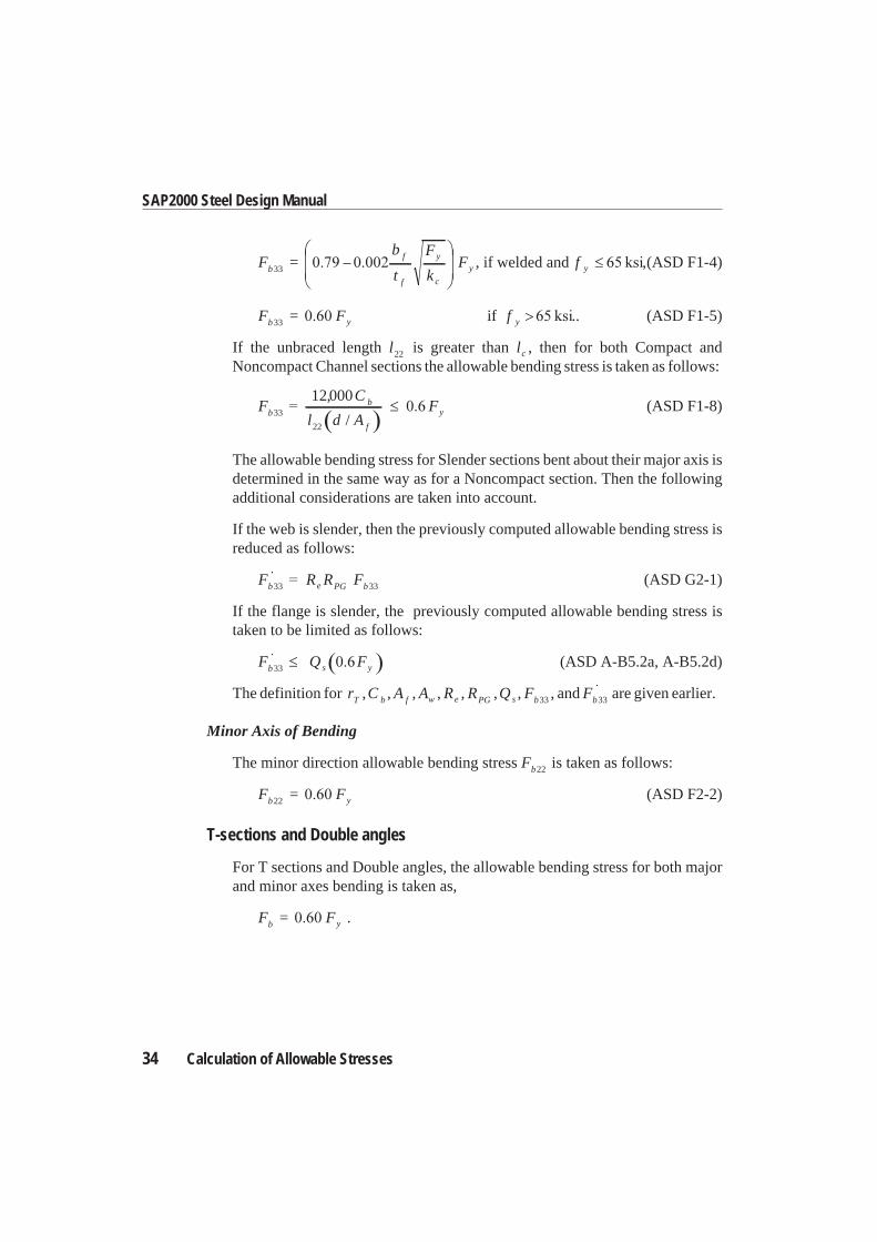
F =b
t
F
kFb
f
f
y
c
y33 , if welded and f y ,(ASD F1-4)
F = Fb y33 if f y .. (ASD F1-5)
If the unbraced length l22 is greater than lc , then for both Compact andNoncompact Channel sections the allowable bending stress is taken as follows:
FC
l d AFb
b
f
y33
22
12000,
/(ASD F1-8)
The allowable bending stress for Slender sections bent about their major axis isdetermined in the same way as for a Noncompact section. Then the followingadditional considerations are taken into account.
If the web is slender, then the previously computed allowable bending stress isreduced as follows:
F R R Fb e PG b33 33 (ASD G2-1)
If the flange is slender, the previously computed allowable bending stress istaken to be limited as follows:
F Q Fb s y33 (ASD A-B5.2a, A-B5.2d)
The definition for rT ,C b , A f , Aw , Re , RPG ,Qs , Fb33 , and Fb33 are given earlier.
Minor Axis of Bending
The minor direction allowable bending stress Fb22 is taken as follows:
F = Fb y22 (ASD F2-2)
T-sections and Double angles
For T sections and Double angles, the allowable bending stress for both majorand minor axes bending is taken as,
F = Fb y .
34 Calculation of Allowable Stresses
SAP2000 Steel Design Manual
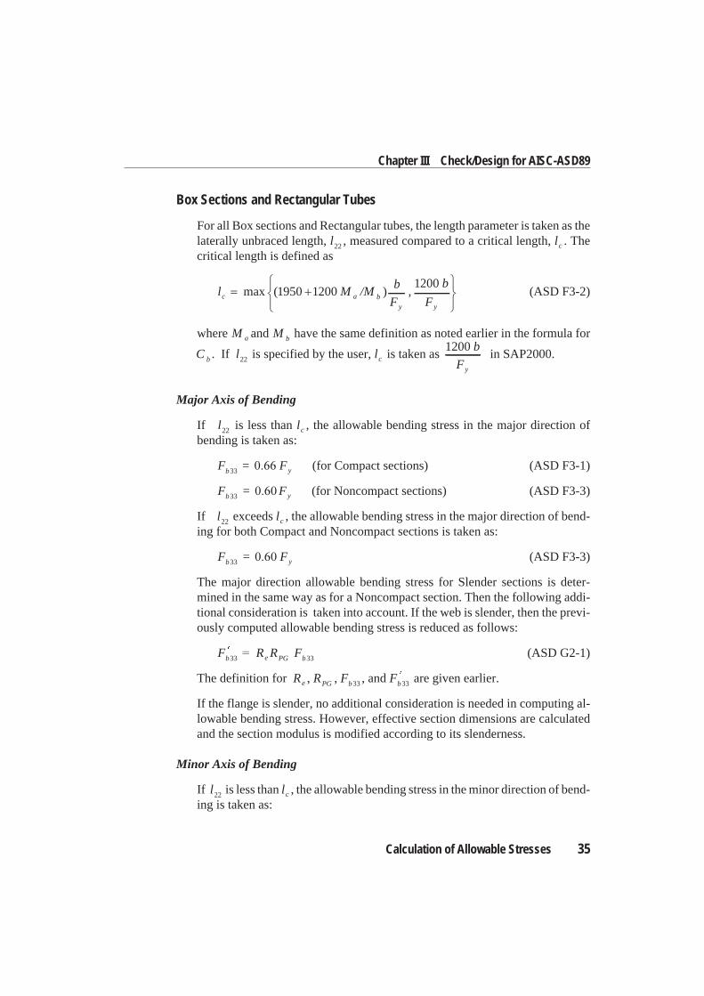
Box Sections and Rectangular Tubes
For all Box sections and Rectangular tubes, the length parameter is taken as thelaterally unbraced length, l22 , measured compared to a critical length, lc . Thecritical length is defined as
l M /Mb
F,
b
Fc a b
y y
max ( )1950 12001200
(ASD F3-2)
where M a and M b have the same definition as noted earlier in the formula for
C b . If l22 is specified by the user, lc is taken as1200 b
Fy
in SAP2000.
Major Axis of Bending
If l22 is less than lc , the allowable bending stress in the major direction ofbending is taken as:
F = Fb y33 (for Compact sections) (ASD F3-1)
F = Fb y33 (for Noncompact sections) (ASD F3-3)
If l22 exceeds lc , the allowable bending stress in the major direction of bend-ing for both Compact and Noncompact sections is taken as:
F = Fb y33 (ASD F3-3)
The major direction allowable bending stress for Slender sections is deter-mined in the same way as for a Noncompact section. Then the following addi-tional consideration is taken into account. If the web is slender, then the previ-ously computed allowable bending stress is reduced as follows:
F R R Fb e PG b33 33 (ASD G2-1)
The definition for Re , RPG , Fb33 , and Fb33 are given earlier.
If the flange is slender, no additional consideration is needed in computing al-lowable bending stress. However, effective section dimensions are calculatedand the section modulus is modified according to its slenderness.
Minor Axis of Bending
If l22 is less than lc , the allowable bending stress in the minor direction of bend-ing is taken as:
Calculation of Allowable Stresses 35
Chapter III Check/Design for AISC-ASD89
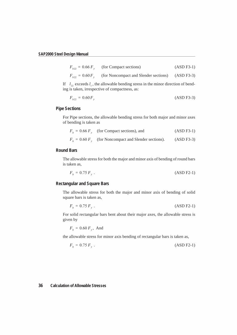
F = Fb y22 (for Compact sections) (ASD F3-1)
F = Fb y22 (for Noncompact and Slender sections) (ASD F3-3)
If l22 exceeds lc , the allowable bending stress in the minor direction of bend-ing is taken, irrespective of compactness, as:
F = Fb y22 (ASD F3-3)
Pipe Sections
For Pipe sections, the allowable bending stress for both major and minor axesof bending is taken as
F = Fb y (for Compact sections), and (ASD F3-1)
F = Fb y (for Noncompact and Slender sections). (ASD F3-3)
Round Bars
The allowable stress for both the major and minor axis of bending of round barsis taken as,
F = Fb y . (ASD F2-1)
Rectangular and Square Bars
The allowable stress for both the major and minor axis of bending of solidsquare bars is taken as,
F = Fb y . (ASD F2-1)
For solid rectangular bars bent about their major axes, the allowable stress isgiven by
F = Fb y , And
the allowable stress for minor axis bending of rectangular bars is taken as,
F = Fb y . (ASD F2-1)
36 Calculation of Allowable Stresses
SAP2000 Steel Design Manual
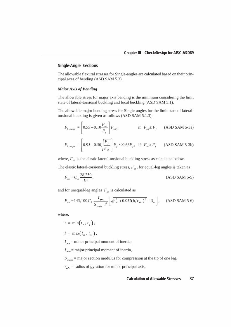
Single-Angle Sections
The allowable flexural stresses for Single-angles are calculated based on their prin-cipal axes of bending (ASD SAM 5.3).
Major Axis of Bending
The allowable stress for major axis bending is the minimum considering the limitstate of lateral-torsional buckling and local buckling (ASD SAM 5.1).
The allowable major bending stress for Single-angles for the limit state of lateral-torsional buckling is given as follows (ASD SAM 5.1.3):
F =F
FFb major
ob
yob, , if F Fob y (ASD SAM 5-3a)
F =F
FF Fb major
y
ob
y y, , if F Fob y (ASD SAM 5-3b)
where, Fob is the elastic lateral-torsional buckling stress as calculated below.
The elastic lateral-torsional buckling stress, Fob , for equal-leg angles is taken as
F Cl tob b , (ASD SAM 5-5)
and for unequal-leg angles Fob is calculated as
F CI
S llt rob b
major
w w2
2 2( ) , (ASD SAM 5-6)
where,
t t tw fmin , ,
l l lmax ,22 33 ,
I = minor principal moment of inertia,
I = major principal moment of inertia,
S major = major section modulus for compression at the tip of one leg,
r = radius of gyration for minor principal axis,
Calculation of Allowable Stresses 37
Chapter III Check/Design for AISC-ASD89
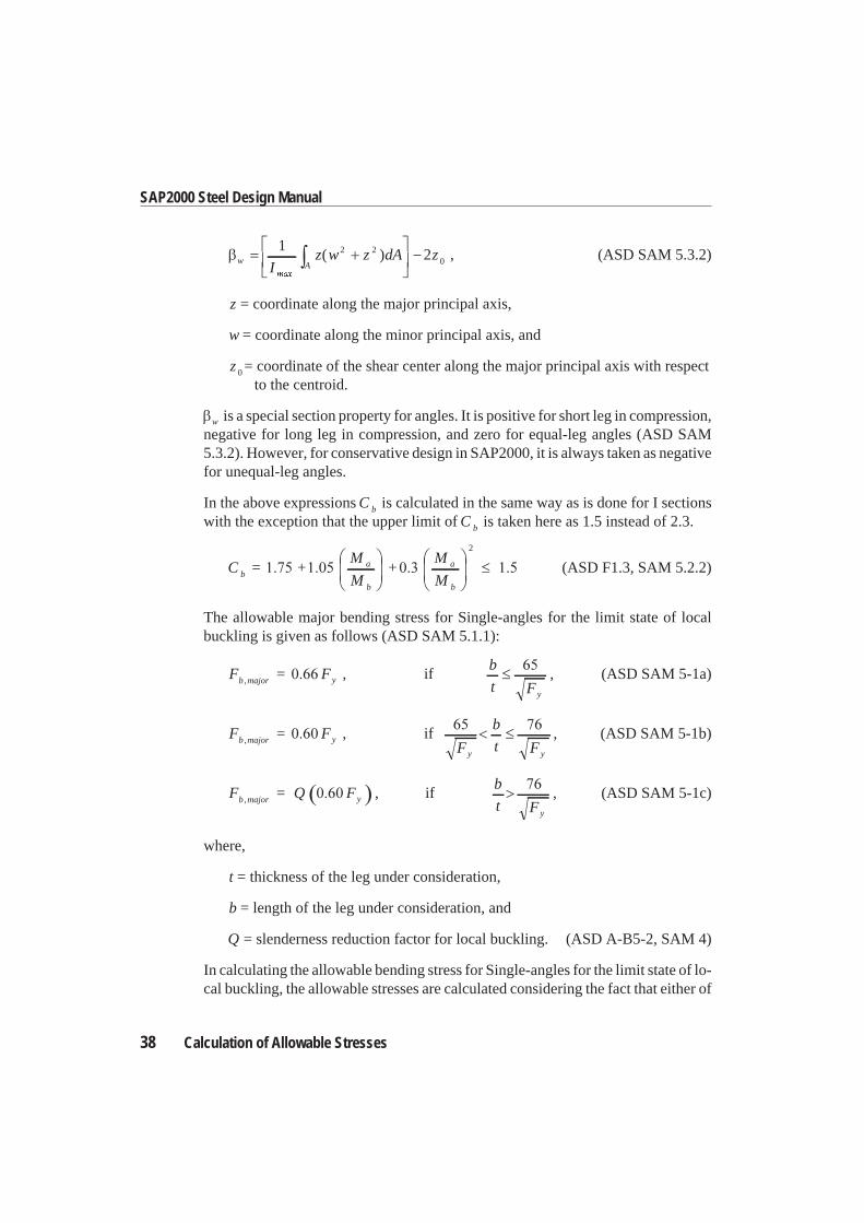
w AIz w z dA z
122 2
0( ) , (ASD SAM 5.3.2)
z = coordinate along the major principal axis,
w = coordinate along the minor principal axis, and
z 0 = coordinate of the shear center along the major principal axis with respectto the centroid.
w is a special section property for angles. It is positive for short leg in compression,negative for long leg in compression, and zero for equal-leg angles (ASD SAM5.3.2). However, for conservative design in SAP2000, it is always taken as negativefor unequal-leg angles.
In the above expressions C b is calculated in the same way as is done for I sectionswith the exception that the upper limit of C b is taken here as 1.5 instead of 2.3.
C = +M
M+
M
Mba
b
a
b
2
(ASD F1.3, SAM 5.2.2)
The allowable major bending stress for Single-angles for the limit state of localbuckling is given as follows (ASD SAM 5.1.1):
F = Fb major y, , ifb
t Fy
, (ASD SAM 5-1a)
F = Fb major y, , ifF
b
t Fy y
, (ASD SAM 5-1b)
F = Q Fb major y, , ifb
t Fy
, (ASD SAM 5-1c)
where,
t = thickness of the leg under consideration,
b = length of the leg under consideration, and
Q = slenderness reduction factor for local buckling. (ASD A-B5-2, SAM 4)
In calculating the allowable bending stress for Single-angles for the limit state of lo-cal buckling, the allowable stresses are calculated considering the fact that either of
38 Calculation of Allowable Stresses
SAP2000 Steel Design Manual
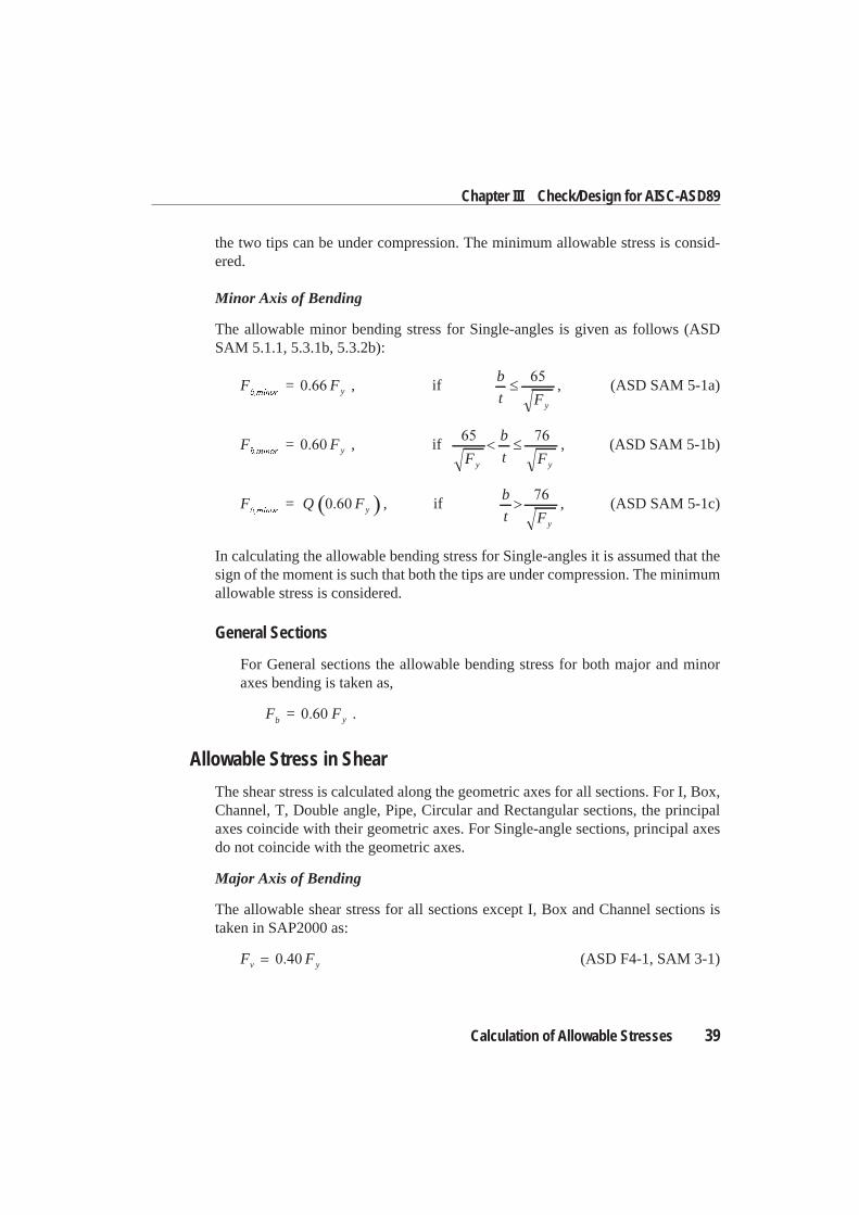
the two tips can be under compression. The minimum allowable stress is consid-ered.
Minor Axis of Bending
The allowable minor bending stress for Single-angles is given as follows (ASDSAM 5.1.1, 5.3.1b, 5.3.2b):
F = Fy , ifb
t Fy
, (ASD SAM 5-1a)
F = Fy , ifF
b
t Fy y
, (ASD SAM 5-1b)
F = Q Fy , ifb
t Fy
, (ASD SAM 5-1c)
In calculating the allowable bending stress for Single-angles it is assumed that thesign of the moment is such that both the tips are under compression. The minimumallowable stress is considered.
General Sections
For General sections the allowable bending stress for both major and minoraxes bending is taken as,
F = Fb y .
Allowable Stress in Shear
The shear stress is calculated along the geometric axes for all sections. For I, Box,Channel, T, Double angle, Pipe, Circular and Rectangular sections, the principalaxes coincide with their geometric axes. For Single-angle sections, principal axesdo not coincide with the geometric axes.
Major Axis of Bending
The allowable shear stress for all sections except I, Box and Channel sections istaken in SAP2000 as:
F Fv y (ASD F4-1, SAM 3-1)
Calculation of Allowable Stresses 39
Chapter III Check/Design for AISC-ASD89
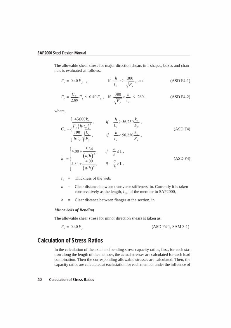
The allowable shear stress for major direction shears in I-shapes, boxes and chan-nels is evaluated as follows:
F Fv y , ifh
t Fw y
380, and (ASD F4-1)
FC
F Fvv
y y , ifF
h
ty w
. (ASD F4-2)
where,
C
k
F h tif
h
t
k
F
h t
k
Fif
h
t
v
v
y w w
v
y
w
v
y
450002
,, ,
,w
v
y
k
F,
(ASD F4)
ka h
ifa
h
a hif
a
h
v
2
2
1
1
, ,
, ,(ASD F4)
tw = Thickness of the web,
a = Clear distance between transverse stiffeners, in. Currently it is takenconservatively as the length, l22 , of the member in SAP2000,
h = Clear distance between flanges at the section, in.
Minor Axis of Bending
The allowable shear stress for minor direction shears is taken as:
F Fv y (ASD F4-1, SAM 3-1)
Calculation of Stress RatiosIn the calculation of the axial and bending stress capacity ratios, first, for each sta-tion along the length of the member, the actual stresses are calculated for each loadcombination. Then the corresponding allowable stresses are calculated. Then, thecapacity ratios are calculated at each station for each member under the influence of
40 Calculation of Stress Ratios
SAP2000 Steel Design Manual
each of the design load combinations. The controlling capacity ratio is then ob-tained, along with the associated station and load combination. A capacity ratiogreater than 1.0 indicates an overstress.
During the design, the effect of the presence of bolts or welds is not considered.Also, the joints are not designed.
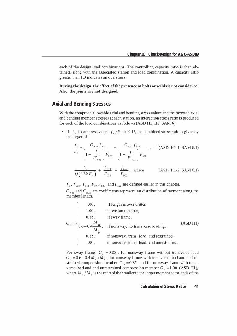
Axial and Bending Stresses
With the computed allowable axial and bending stress values and the factored axialand bending member stresses at each station, an interaction stress ratio is producedfor each of the load combinations as follows (ASD H1, H2, SAM 6):
• If f a is compressive and f Fa a , the combined stress ratio is given bythe larger of
f
F+
C f
f
F'F
+C fa
a
m b
a
e
b
m b33 33
33
33
22 22
1 1f
F'Fa
e
b
22
22
, and (ASD H1-1, SAM 6.1)
f
F
f
F
f
Fa
y
b
b
b
b
33
33
22
22
, where (ASD H1-2, SAM 6.1)
f a , f b33 , f b22 , Fa , Fb33 , and Fb22 are defined earlier in this chapter,
C m33 and C m22 are coefficients representing distribution of moment along themember length.
C mM
aM
b
,(ASD H1)
For sway frame C m , for nonsway frame without transverse loadC M Mm a b , for nonsway frame with transverse load and end re-strained compression member C m , and for nonsway frame with trans-verse load and end unrestrained compression member C m (ASD H1),where M Ma b is the ratio of the smaller to the larger moment at the ends of the
Calculation of Stress Ratios 41
Chapter III Check/Design for AISC-ASD89
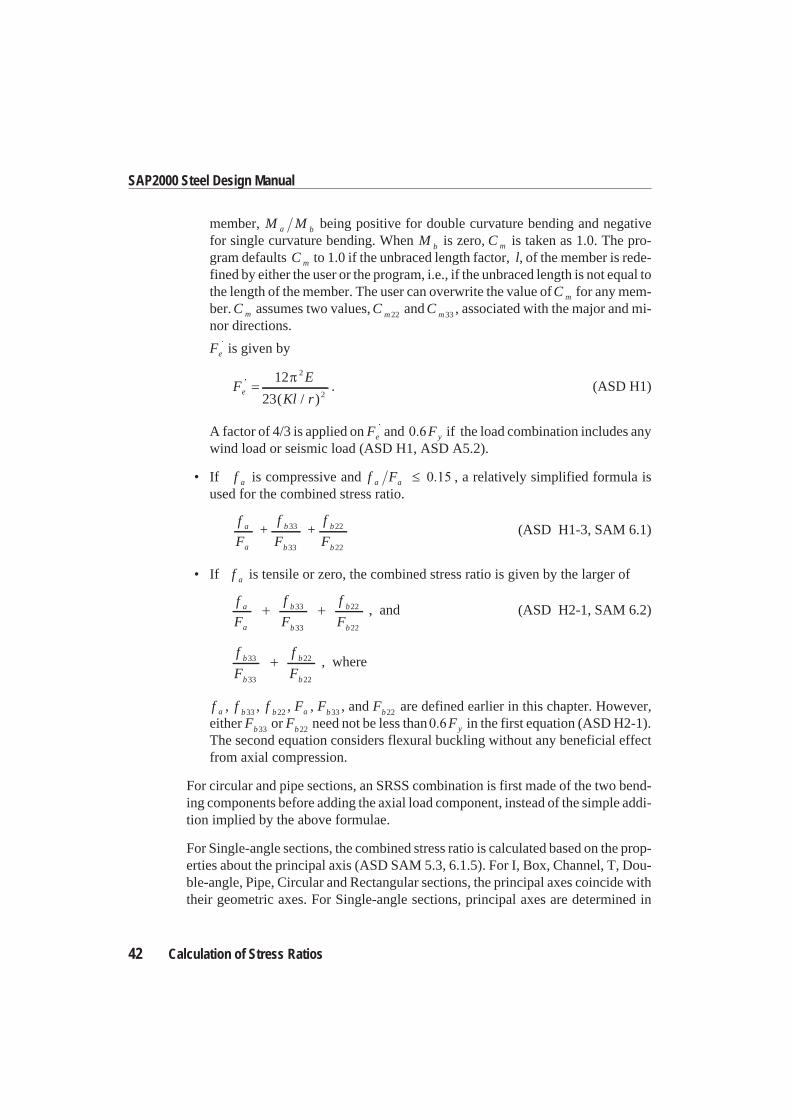
member, M Ma b being positive for double curvature bending and negativefor single curvature bending. When M b is zero, C m is taken as 1.0. The pro-gram defaults C m to 1.0 if the unbraced length factor, l, of the member is rede-fined by either the user or the program, i.e., if the unbraced length is not equal tothe length of the member. The user can overwrite the value ofC m for any mem-ber. C m assumes two values, C m22 and C m33 , associated with the major and mi-nor directions.
Fe is given by
FE
Kl re
12
23
2
2( / ). (ASD H1)
A factor of 4/3 is applied on Fe and Fy if the load combination includes anywind load or seismic load (ASD H1, ASD A5.2).
• If f a is compressive and f Fa a , a relatively simplified formula isused for the combined stress ratio.
f
F+
f
F+
f
Fa
a
b
b
b
b
33
33
22
22
(ASD H1-3, SAM 6.1)
• If f a is tensile or zero, the combined stress ratio is given by the larger of
f
F
f
F
f
Fa
a
b
b
b
b
33
33
22
22
, and (ASD H2-1, SAM 6.2)
f
F
f
Fb
b
b
b
33
33
22
22
, where
f a , f b33 , f b22 , Fa , Fb33 , and Fb22 are defined earlier in this chapter. However,either Fb33 or Fb22 need not be less than Fy in the first equation (ASD H2-1).The second equation considers flexural buckling without any beneficial effectfrom axial compression.
For circular and pipe sections, an SRSS combination is first made of the two bend-ing components before adding the axial load component, instead of the simple addi-tion implied by the above formulae.
For Single-angle sections, the combined stress ratio is calculated based on the prop-erties about the principal axis (ASD SAM 5.3, 6.1.5). For I, Box, Channel, T, Dou-ble-angle, Pipe, Circular and Rectangular sections, the principal axes coincide withtheir geometric axes. For Single-angle sections, principal axes are determined in
42 Calculation of Stress Ratios
SAP2000 Steel Design Manual
SAP2000. For general sections no effort is made to determine the principal direc-tions.
When designing for combinations involving earthquake and wind loads, allowablestresses are increased by a factor of 4/3 of the regular allowable value (ASD A5.2).
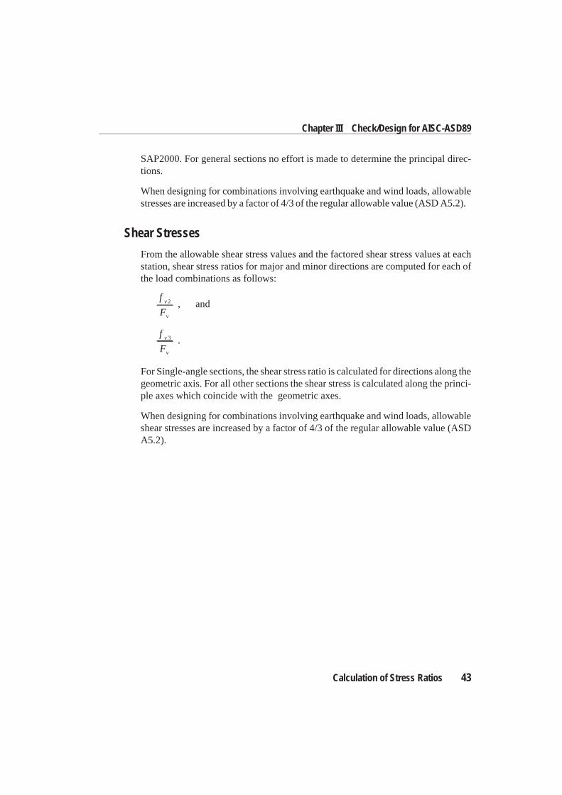
Shear Stresses
From the allowable shear stress values and the factored shear stress values at eachstation, shear stress ratios for major and minor directions are computed for each ofthe load combinations as follows:
f
Fv
v
2 , and
f
Fv
v
3 .
For Single-angle sections, the shear stress ratio is calculated for directions along thegeometric axis. For all other sections the shear stress is calculated along the princi-ple axes which coincide with the geometric axes.
When designing for combinations involving earthquake and wind loads, allowableshear stresses are increased by a factor of 4/3 of the regular allowable value (ASDA5.2).
Calculation of Stress Ratios 43
Chapter III Check/Design for AISC-ASD89
Related Documents