POLITECNICO DI TORINO Design of a distributed control unit for reconfigurable CNN accelerators Corso di Laurea in Embedded system Tesi di Laurea Magistrale Relatore Prof. Andrea Calimera Correlatore: Dott. Valerio Tenace Nicolò Morando matricola: 231924 Anno accademico !"#$ – !"#%

Welcome message from author
This document is posted to help you gain knowledge. Please leave a comment to let me know what you think about it! Share it to your friends and learn new things together.
Transcript
POLITECNICO DI TORINO
Design of a distributed controlunit for reconfigurable CNN
accelerators
Corso di Laurea in Embedded system
Tesi di Laurea Magistrale
RelatoreProf. Andrea Calimera
Correlatore:Dott. Valerio Tenace
Nicolò Morandomatricola: 231924
Anno accademico !"#$ – !"#%
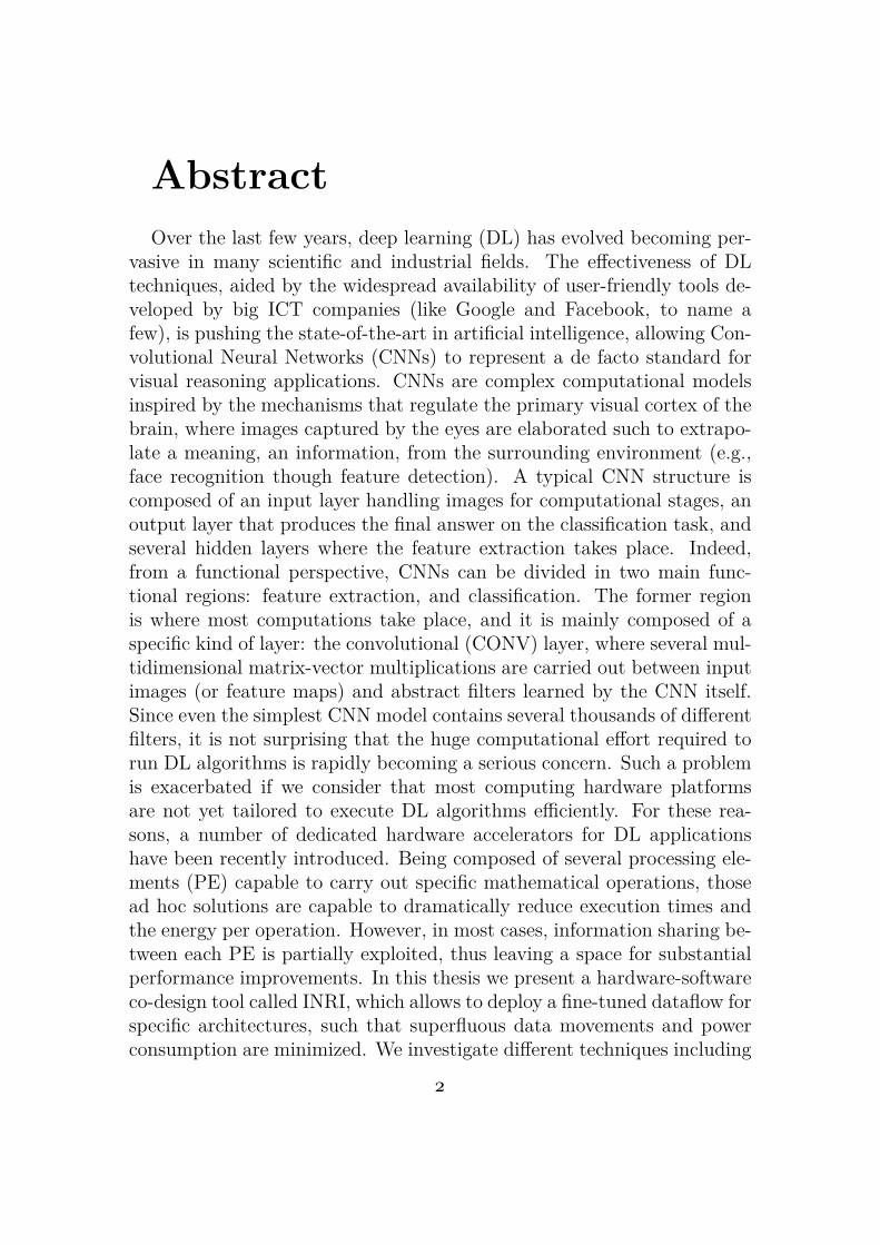
AbstractOver the last few years, deep learning (DL) has evolved becoming per-
vasive in many scientific and industrial fields. The effectiveness of DLtechniques, aided by the widespread availability of user-friendly tools de-veloped by big ICT companies (like Google and Facebook, to name afew), is pushing the state-of-the-art in artificial intelligence, allowing Con-volutional Neural Networks (CNNs) to represent a de facto standard forvisual reasoning applications. CNNs are complex computational modelsinspired by the mechanisms that regulate the primary visual cortex of thebrain, where images captured by the eyes are elaborated such to extrapo-late a meaning, an information, from the surrounding environment (e.g.,face recognition though feature detection). A typical CNN structure iscomposed of an input layer handling images for computational stages, anoutput layer that produces the final answer on the classification task, andseveral hidden layers where the feature extraction takes place. Indeed,from a functional perspective, CNNs can be divided in two main func-tional regions: feature extraction, and classification. The former regionis where most computations take place, and it is mainly composed of aspecific kind of layer: the convolutional (CONV) layer, where several mul-tidimensional matrix-vector multiplications are carried out between inputimages (or feature maps) and abstract filters learned by the CNN itself.Since even the simplest CNN model contains several thousands of differentfilters, it is not surprising that the huge computational effort required torun DL algorithms is rapidly becoming a serious concern. Such a problemis exacerbated if we consider that most computing hardware platformsare not yet tailored to execute DL algorithms efficiently. For these rea-sons, a number of dedicated hardware accelerators for DL applicationshave been recently introduced. Being composed of several processing ele-ments (PE) capable to carry out specific mathematical operations, thosead hoc solutions are capable to dramatically reduce execution times andthe energy per operation. However, in most cases, information sharing be-tween each PE is partially exploited, thus leaving a space for substantialperformance improvements. In this thesis we present a hardware-softwareco-design tool called INRI, which allows to deploy a fine-tuned dataflow forspecific architectures, such that superfluous data movements and powerconsumption are minimized. We investigate different techniques including
!
data reuse, smart activation/deactivation policies for PE in the idle state,and specific pixel-clustering algorithms. The performance of the proposedtool are supported by experimental results obtained with different hard-ware configurations running well-known CNN models, such as AlexNet,VGG-16 and ZFNet. Results demonstrate that our approach is capableto reduce the energy of CNNs by 25%, still guaranteeing an acceptableaccuracy loss of 2%.
"
AcknowledgementsI would like to to thank Professor Andrea Calimera for giving me the
opportunity to collaborate with him to this project. Another special thankto Valerio Tenace for helping and supporting me during this work .
#

Contents
List of Tables 8
List of Figures 9
1 Introduction 131.1 Motivation . . . . . . . . . . . . . . . . . . . . . . . . . . . 131.2 Related Work . . . . . . . . . . . . . . . . . . . . . . . . . 141.3 Purpose and research questions . . . . . . . . . . . . . . . 151.4 Approach and Methodology . . . . . . . . . . . . . . . . . 151.5 Scope and Limitation . . . . . . . . . . . . . . . . . . . . . 151.6 Outline . . . . . . . . . . . . . . . . . . . . . . . . . . . . . 16
2 Theoretical Background 172.1 Introduction . . . . . . . . . . . . . . . . . . . . . . . . . . 172.2 CNN Overview . . . . . . . . . . . . . . . . . . . . . . . . 18
2.2.1 Convolution . . . . . . . . . . . . . . . . . . . . . . 192.2.2 Pooling . . . . . . . . . . . . . . . . . . . . . . . . 212.2.3 Fully connected . . . . . . . . . . . . . . . . . . . . 222.2.4 Padding . . . . . . . . . . . . . . . . . . . . . . . . 242.2.5 Non Linearity (ReLU) . . . . . . . . . . . . . . . . 25
2.3 CNN architecture . . . . . . . . . . . . . . . . . . . . . . . 272.3.1 AlexNet . . . . . . . . . . . . . . . . . . . . . . . . 272.3.2 ZfNet . . . . . . . . . . . . . . . . . . . . . . . . . 292.3.3 VGG16 . . . . . . . . . . . . . . . . . . . . . . . . 30
3 Hardware architecture for CNN 313.1 CHAIN PE . . . . . . . . . . . . . . . . . . . . . . . . . . 333.2 PE Matrix . . . . . . . . . . . . . . . . . . . . . . . . . . . 36
$
4 Hardware software co-design for CNN 394.1 Dispatcher . . . . . . . . . . . . . . . . . . . . . . . . . . . 41
4.1.1 Hardware . . . . . . . . . . . . . . . . . . . . . . . 424.1.2 Software . . . . . . . . . . . . . . . . . . . . . . . . 43
4.2 Pixel Clustering . . . . . . . . . . . . . . . . . . . . . . . . 444.2.1 Hardware . . . . . . . . . . . . . . . . . . . . . . . 454.2.2 Software . . . . . . . . . . . . . . . . . . . . . . . . 46
4.3 CNN simulator framework . . . . . . . . . . . . . . . . . . 46
5 Results 495.1 Experimental Setup . . . . . . . . . . . . . . . . . . . . . . 49
5.1.1 Dataset . . . . . . . . . . . . . . . . . . . . . . . . 505.1.2 Program languages and frameworks . . . . . . . . . 505.1.3 Hardware simulation . . . . . . . . . . . . . . . . . 505.1.4 Pixel Clustering . . . . . . . . . . . . . . . . . . . . 505.1.5 Result comparison . . . . . . . . . . . . . . . . . . 515.1.6 Result comparison2 . . . . . . . . . . . . . . . . . . 51
5.2 Memory access . . . . . . . . . . . . . . . . . . . . . . . . 515.3 Accuracy . . . . . . . . . . . . . . . . . . . . . . . . . . . . 535.4 Prediction . . . . . . . . . . . . . . . . . . . . . . . . . . . 545.5 Bottom-up: training and testing a CNN architecture with
INRI . . . . . . . . . . . . . . . . . . . . . . . . . . . . . . 545.6 Area & power consumption . . . . . . . . . . . . . . . . . 55
5.6.1 Area . . . . . . . . . . . . . . . . . . . . . . . . . . 555.6.2 Energy & Power consumption . . . . . . . . . . . . 55
6 Conclusion 59
7 FIles 61
Bibliography 63
A image_converter.py 65
B comparison_result.py 67
C comparison_result.py pt2 69
D performance_extractor 71%
E Processing_Element.vhd 75
F Pixel_Clustering.vhd 77
&
List of Tables3.1 . . . . . . . . . . . . . . . . . . . . . . . . . . . . . . . . . 354.1 Synthesis results . . . . . . . . . . . . . . . . . . . . . . . 475.1 Area results . . . . . . . . . . . . . . . . . . . . . . . . . . 565.2 power consumption . . . . . . . . . . . . . . . . . . . . . . 565.3 power & energy consumption . . . . . . . . . . . . . . . . 56
’
List of Figures
2.1 LeNet CNN architecture [14] . . . . . . . . . . . . . . . . . 192.2 convolution on an image 3x5x5 with padding=1 with a ker-
nel 3x3x3[16] . . . . . . . . . . . . . . . . . . . . . . . . . 202.3 example of applications of max and average pooling [15] . 212.4 fully connected layer [17] . . . . . . . . . . . . . . . . . . . 222.5 Overview of a ANN[29] . . . . . . . . . . . . . . . . . . . . 232.6 hidden layer in detail[29] . . . . . . . . . . . . . . . . . . . 232.7 the original size is 32x32x3. After applying a padding=2
now we have 36x36x3[20] . . . . . . . . . . . . . . . . . . . 242.8 relu representation[6] . . . . . . . . . . . . . . . . . . . . . 252.9 image which applied relu[6] . . . . . . . . . . . . . . . . . 262.10 overall AlexNet architecture [25] . . . . . . . . . . . . . . . 282.11 overall ZfNet architecture [26] . . . . . . . . . . . . . . . . 292.12 Vgg19 architecture [27] . . . . . . . . . . . . . . . . . . . 303.1 PE logic block rappresentation . . . . . . . . . . . . . . . . 323.2 PE logic block rappresentation[23] . . . . . . . . . . . . . . 333.3 An example of how a 1D chain architecture is divided into
cascaded systolic primitives for various kernel size K [23] . 343.4 Each pipeline stage forms a basic process engine (PE). The
cascading PEs form a 1D systolic architecture for a 2D con-volution operation[23] . . . . . . . . . . . . . . . . . . . . . 35
3.5 PE Matrix overview [11] . . . . . . . . . . . . . . . . . . . 363.6 LowPE Matrix overview [11] . . . . . . . . . . . . . . . . . 374.1 growth comparison among CPU and DRAM [8] . . . . . . 394.2 INRI design representation . . . . . . . . . . . . . . . . . . 404.3 example of dispatcher execution flow . . . . . . . . . . . . 434.4 Software dataflow . . . . . . . . . . . . . . . . . . . . . . . 444.5 word cell rappresentation . . . . . . . . . . . . . . . . . . . 45
(
4.6 Pixel Clustering application . . . . . . . . . . . . . . . . . 464.7 On left the original picture, on the right the same image
with pixel clustering applied with cluster =4and threshold= 5. Even through they look like the same picture, thesecond image feed as input in INRI architecture reducesthe memory access 4 times lower. . . . . . . . . . . . . . . 47
4.8 . . . . . . . . . . . . . . . . . . . . . . . . . . . . . . . . . 485.1 . . . . . . . . . . . . . . . . . . . . . . . . . . . . . . . . . 525.2 . . . . . . . . . . . . . . . . . . . . . . . . . . . . . . . . . 525.3 . . . . . . . . . . . . . . . . . . . . . . . . . . . . . . . . . 525.4 CNN comparison with g=4 . . . . . . . . . . . . . . . . . . 535.5 CNN comparison with g=7 . . . . . . . . . . . . . . . . . . 545.6 . . . . . . . . . . . . . . . . . . . . . . . . . . . . . . . . . 57
)*
Summary
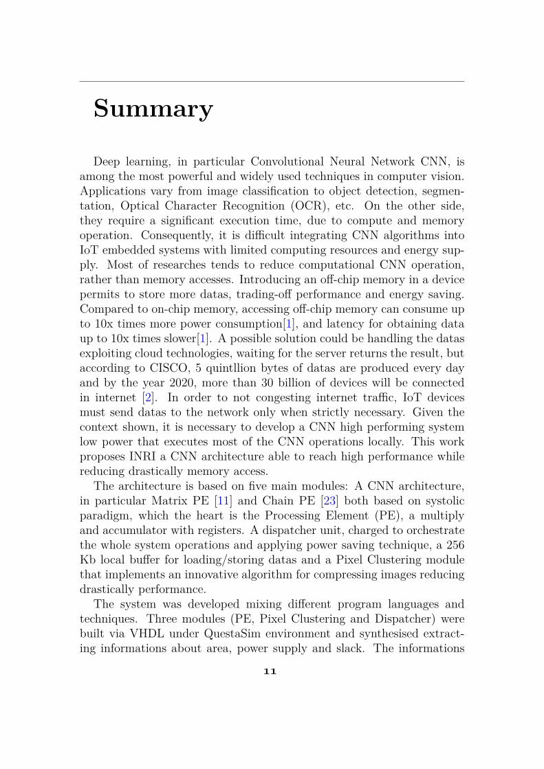
Deep learning, in particular Convolutional Neural Network CNN, isamong the most powerful and widely used techniques in computer vision.Applications vary from image classification to object detection, segmen-tation, Optical Character Recognition (OCR), etc. On the other side,they require a significant execution time, due to compute and memoryoperation. Consequently, it is difficult integrating CNN algorithms intoIoT embedded systems with limited computing resources and energy sup-ply. Most of researches tends to reduce computational CNN operation,rather than memory accesses. Introducing an off-chip memory in a devicepermits to store more datas, trading-off performance and energy saving.Compared to on-chip memory, accessing off-chip memory can consume upto 10x times more power consumption[1], and latency for obtaining dataup to 10x times slower[1]. A possible solution could be handling the datasexploiting cloud technologies, waiting for the server returns the result, butaccording to CISCO, 5 quintllion bytes of datas are produced every dayand by the year 2020, more than 30 billion of devices will be connectedin internet [2]. In order to not congesting internet traffic, IoT devicesmust send datas to the network only when strictly necessary. Given thecontext shown, it is necessary to develop a CNN high performing systemlow power that executes most of the CNN operations locally. This workproposes INRI a CNN architecture able to reach high performance whilereducing drastically memory access.
The architecture is based on five main modules: A CNN architecture,in particular Matrix PE [11] and Chain PE [23] both based on systolicparadigm, which the heart is the Processing Element (PE), a multiplyand accumulator with registers. A dispatcher unit, charged to orchestratethe whole system operations and applying power saving technique, a 256Kb local buffer for loading/storing datas and a Pixel Clustering modulethat implements an innovative algorithm for compressing images reducingdrastically performance.
The system was developed mixing different program languages andtechniques. Three modules (PE, Pixel Clustering and Dispatcher) werebuilt via VHDL under QuestaSim environment and synthesised extract-ing informations about area, power supply and slack. The informations
!!
Nicolò Morando et al.
obtained are integrated in a tool built in C language, able to return anaccurate approximation about area, energy, power consumption and clocklatency for operation of the system. The prediction was analysed sim-ulating the system using Python with Keras frameworks, implementingthree CNN architectures with pre-trained filter values: AlexNet, ZfNetand VGG16. Results demonstrate that is possible to achieve a significantmemory access reduction up to 4x times lower compared to a traditionalarchitecture without any memory access reduction techniques having anaverage accuracy drop around 6%.
!"
Chapter 1
Introduction
1.1 MotivationDuring last years Machine Learning has obtained the supremacy on com-puter vision tasks occupying more and more a significant part of ourlifes. This phenomenon can be attribuited to its ability to get high accu-racy, ranging from object recognition and detection. With the boostingof amount of data, it is smart to think that technological progress willbe heavily influenced from smart data analysis. On the other side, Ma-chine Learning algorithms require a significant execution time, due tocompute and memory operation. Consequently, it is difficult implementCNN algorithms into IoT embedded systems with low hardware resourcesand energy supply. Majority of the works try to investigate how to en-hance computational efficiency solutions of CNNs, leaving memory effi-ciency largely overlooked. Introducing an off-chip memory in a devicepermits to store more datas, trading-off performance and energy saving.Compared to on-chip memory, accessing off-chip memory can consume upto 10x times more power consumption[1], and latency for obtaining dataup to 10x times [1]. Under these circumstances, it’s necessary to developa CNN system able to reduce power consumption, without affecting theoverall performance of the system.
In this work is described INRI, a dataflow for CNN architecture thatuses different techniques such as data reuse, local buffer, activation/de-activation processing element(PE) and a compression algorithm in orderto achieve high performance with a contained power consumption. Thehardware part of the work, was built using HDL language (in particular
)"
Nicolò Morando et al.
VHDL) and C language. For software counterpart was used Python sup-ported by Keras framework. The architecture is composed of a dispatcher,in charge of handling, executing and monitorate the system, a CNN basedon systolic architecture that execute operations, a local buffer for storagedatas and last the Pixel Clustering module used that implements an in-novative compression algorithm for reducing memory access. Comparingto traditional systems, results shown that all these strategies reduce insignificant way the memory access (up to 4 times lower), hence the powerconsumption and clock latency per operation.
1.2 Related WorkDuring the years, different techniques has been exploited for realising per-forming CNN system using different technique such as data reuse, systolicarchitecture ( MATRIX PE[22] or CHAIN PE [23] ) or proposing newdataflows (EYERISS) . Most of state state CNN solutions exploit one ormore of these paradigms in order to achieve high performance.
• weight stationary : For optimising convolutional and filter reuse,every filter weight remains fixed in the register file (RF) inside theprocessing element (PE).
• output stationary: The aggregation of the partial sum(psum) re-mains static in the RF. The output feature map (ofmap) stay in thesame RF for accumulation in order to reduce the psum accumulationcost.
• no local reuse: It uses inter-PE communication for input featuremap (ifmap ) reuse and psum accumulation.
All these paradigms propose interesting solutions for enhancing per-formance of the system, but they consider often the operation efficiencyrather than also analyse memory efficiency. Considering as example thetwo systolic architecture introduced (MATRIX PE[11], CHAIN PE[23]).They suggest useful solutions for executing CNN operations faster, butthey do not answer to the question how to access in a more efficient wayto the datas to manipulate, making the off-chip memory access the bot-tleneck of the system. This research goes to investigate how to enhancingboth memory and execute operations.
!#
1 – Introduction
In summary, the main contributions of this work includes
• data reuse
• hardware optimizations
• test comparison among CNN
• new algorithm able to reduce data movement off-chip to on-chip (pixel clustering)
1.3 Purpose and research questionsThe entire research attempt to reply to the following questions :
• How to realise a high-performance CNN architecture ?
• Is it possible to build a system both performing and low-power con-suming ?
• if is it positive the previous question, how much prediction score isaffected ?
1.4 Approach and MethodologyThe work proposes a high-performance and low-power convolutional neu-ral network architecture (CNNA) exploiting systolic architecture and com-pression algorithms in order to improve efficiency of the system. Differentexperiments were executed in order to obtain the best setup with the low-est hardware implementation. They can be classified in two categories,the former finding the best trade-off among hardware resource and perfor-mance. Second, develop and test how to orchestrate the whole architecturewith best performance power consumption ratio.
1.5 Scope and LimitationThe main purpose of this work is to develop a low-power performing sys-tem with a good image patterns recognition accuracy . The system obtains
!$
Nicolò Morando et al.
an interesting prediction score around 70% (where traditional systems ob-tained an average around 76%) with an average memory access reductionaround 60% compared to a traditional setup. It can be considered a goodresult, but some interesting investigation could be take place.
Considering local buffer. INRI implements SRAM local buffer 256 kb 32bit word cell size.It uses 16 bits for data and 3 bits for implementing Pixel-Clustering algorithm.13 bits does not contain any useful informations.Differents researches demonstrate that data inputs and weights could berepresented that up to 8 bit[12], without loosing significant accuracy Apossible improvements could be reduce the data value to 8 bits in orderto fit both data and algorithm in 16 bits.
Another limitation is data streams inside CNNA, in particular, howinformation pass through processing element (PE) . The communicationamong them happen only in vertical or horizontal way because of limita-tion provided by the algorithm (Pixel Clustering). A further step could atotally freedom PE communication (introducing the oblique data move-ment), modifying the structure.
1.6 OutlineThe report is structured in the following way. Chapter 2 introduce theo-retical background about machine learning, paying attention on artificialneural network, in particular convolution neural network. Chapter 3 ex-plains the motivation behind this paper, describing briefly the streamexecution. Chapther 4 shows in details which technologies were used todevelop and testing the system. Chapter 5 explain in details how architec-ture works and on which technique is based. Chapter 6 describe the resultobtained by experiment, concluding with final considerations in chapter7.
!%
Chapter 2
Theoretical Background
2.1 IntroductionMachine learning is a subfield of artificial intelligence (AI) that permitsto a program to "understand" how to solve a specific purposes with datasreceived, without being explicitly instructed. A more formal definition wasformulated by Tom M. Michell says “A computer program is said to learnfrom experience E with respect to some class of tasks T and performancemeasure P if its performance at tasks in T, as measured by P, improveswith experience E.” [24] Machine learning algorithms can be divided intotwo categories supervised and unsupervised algorithms, depending on howthey "learn" to make predictions
• Supervised algorithms: Supervised learning is the paradigm mostused for machine learning. It is when the program tries to to learn themapping function from the input (X) to the output(Y). The input arethe data send by user for training/testing part, while the outcome isthe prediction value. Learning method can be compared to a studentlearning from a teacher.
Y = f(X)
The purpose is to develop a mapping function that is able to predictthe output variables (Y) when it receives new input data (X) . Com-pared to others solutions, it has the advantages that you can make aperfect decision boundary to distinguish different classes accurately,specifying by user how many classes desire to have and besides aftertraining, it’s not necessary keep the training example in the memory,
)&
Nicolò Morando et al.
it’s necessary just the mathematical forumula “decision boundary”for classifying future inputs. On the other side, the decision mightbe overtrained or it tries to predict decision even through the inputreceived was never classified into a category. Last, the training moderequires a lot of computation time. Typical supervised algorithm arelinear regression, based on a linear equation where the prediction isobtained inserting parameters in the equation formed during training,random forest, that is based on a binary decision tree and supportvector machines:
• Unsupervised algorithms: Unlike supervised learning, in unsuper-vised learning, the answer are not labelled and it is duty of the algo-rithm, to group datas correctly. It acts more closely to "true artificialintelligence" [5]. It is more complex to implement compared to su-pervised algorithms but it permits to the program, to solve problemsnever faced, building new classes.Some popular examples of unsuper-vised learning algorithms are k-means, based on centroid point calledk used as point of reference for building a new class. Each k value is a"cluster" of element belonging to the same class or apriori algorithm .
.
2.2 CNN OverviewCNNs are complex computational models inspired by the mechanisms thatregulate the primary visual cortex of the brain, where images captured bythe eyes are elaborated such to extrapolate a meaning, an information,from the surrounding environment (e.g., face recognition though featuredetection). A typical CNN structure is composed of an input layer han-dling images for computational stages, an output layer that produces thefinal answer on the classification task, and several hidden layers wherethe feature extraction takes place. Indeed, from a functional perspective,CNNs can be divided in two main functional regions: feature extraction,and classification. The former region is where most computations takeplace, and it is mainly composed of a specific kind of layer: the convolu-tional (CONV) layer, where several multidimensional matrix-vector mul-tiplications are carried out between input images (or feature maps) andabstract filters learned by the CNN itself. Typical layers used for CNN are
!&
2 – Theoretical Background
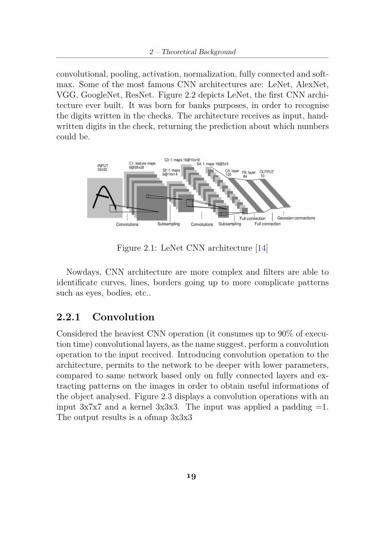
convolutional, pooling, activation, normalization, fully connected and soft-max. Some of the most famous CNN architectures are: LeNet, AlexNet,VGG, GoogleNet, ResNet. Figure 2.2 depicts LeNet, the first CNN archi-tecture ever built. It was born for banks purposes, in order to recognisethe digits written in the checks. The architecture receives as input, hand-written digits in the check, returning the prediction about which numberscould be.
Figure 2.1: LeNet CNN architecture [14]
Nowdays, CNN architecture are more complex and filters are able toidentificate curves, lines, borders going up to more complicate patternssuch as eyes, bodies, etc..
2.2.1 ConvolutionConsidered the heaviest CNN operation (it consumes up to 90% of execu-tion time) convolutional layers, as the name suggest, perform a convolutionoperation to the input received. Introducing convolution operation to thearchitecture, permits to the network to be deeper with lower parameters,compared to same network based only on fully connected layers and ex-tracting patterns on the images in order to obtain useful informations ofthe object analysed. Figure 2.3 displays a convolution operations with aninput 3x7x7 and a kernel 3x3x3. The input was applied a padding =1.The output results is a ofmap 3x3x3
!’
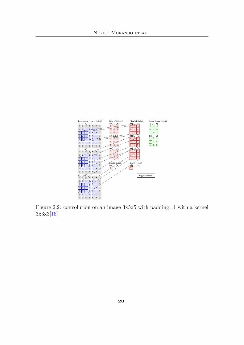
Nicolò Morando et al.
Figure 2.2: convolution on an image 3x5x5 with padding=1 with a kernel3x3x3[16]
"(
2 – Theoretical Background
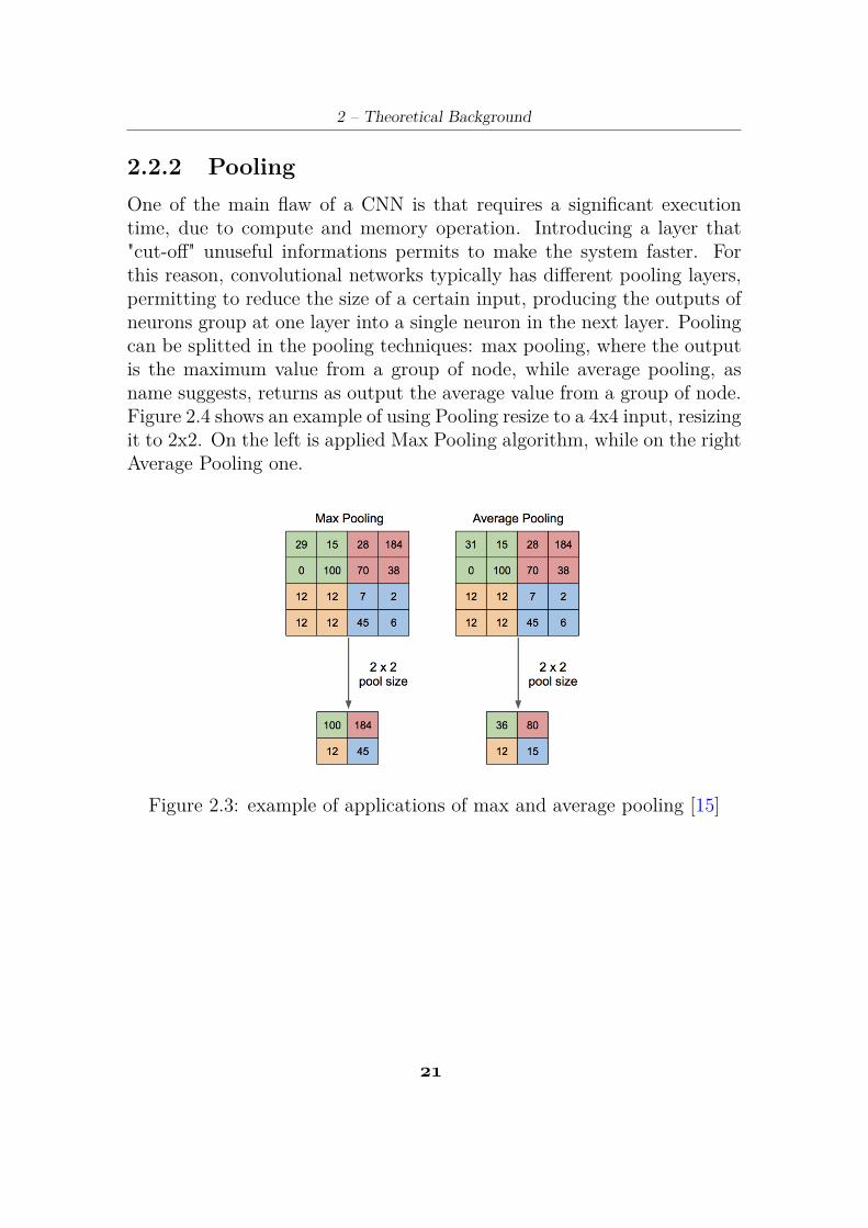
2.2.2 PoolingOne of the main flaw of a CNN is that requires a significant executiontime, due to compute and memory operation. Introducing a layer that"cut-off" unuseful informations permits to make the system faster. Forthis reason, convolutional networks typically has different pooling layers,permitting to reduce the size of a certain input, producing the outputs ofneurons group at one layer into a single neuron in the next layer. Poolingcan be splitted in the pooling techniques: max pooling, where the outputis the maximum value from a group of node, while average pooling, asname suggests, returns as output the average value from a group of node.Figure 2.4 shows an example of using Pooling resize to a 4x4 input, resizingit to 2x2. On the left is applied Max Pooling algorithm, while on the rightAverage Pooling one.
Figure 2.3: example of applications of max and average pooling [15]
"!
Nicolò Morando et al.
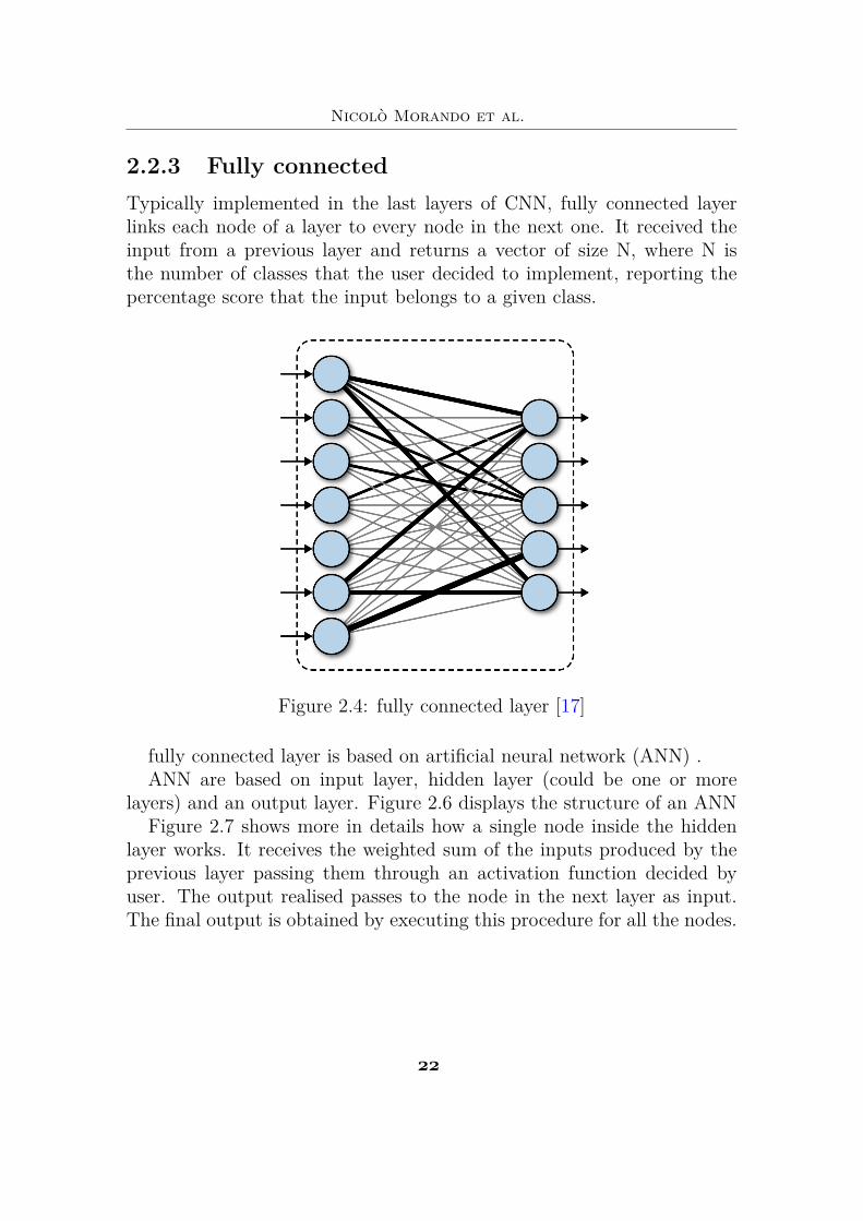
2.2.3 Fully connectedTypically implemented in the last layers of CNN, fully connected layerlinks each node of a layer to every node in the next one. It received theinput from a previous layer and returns a vector of size N, where N isthe number of classes that the user decided to implement, reporting thepercentage score that the input belongs to a given class.
Figure 2.4: fully connected layer [17]
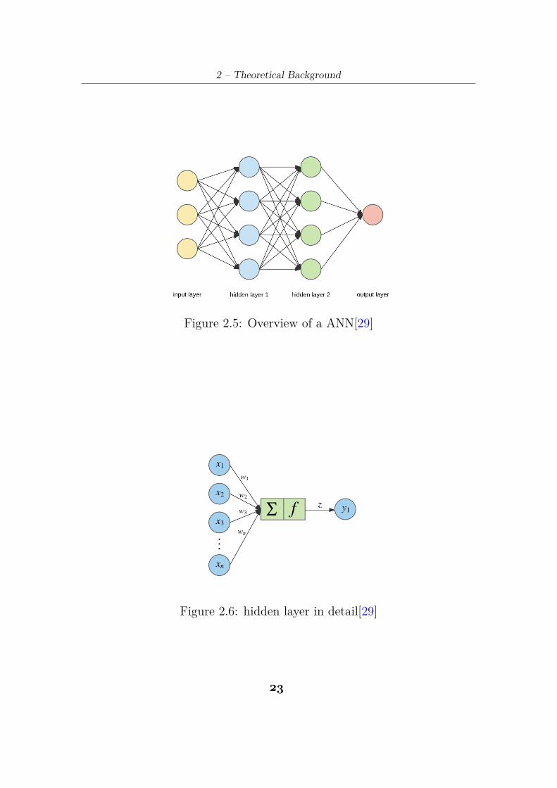
fully connected layer is based on artificial neural network (ANN) .ANN are based on input layer, hidden layer (could be one or more
layers) and an output layer. Figure 2.6 displays the structure of an ANNFigure 2.7 shows more in details how a single node inside the hidden
layer works. It receives the weighted sum of the inputs produced by theprevious layer passing them through an activation function decided byuser. The output realised passes to the node in the next layer as input.The final output is obtained by executing this procedure for all the nodes.
""
2 – Theoretical Background
Figure 2.5: Overview of a ANN[29]
Figure 2.6: hidden layer in detail[29]
")
Nicolò Morando et al.
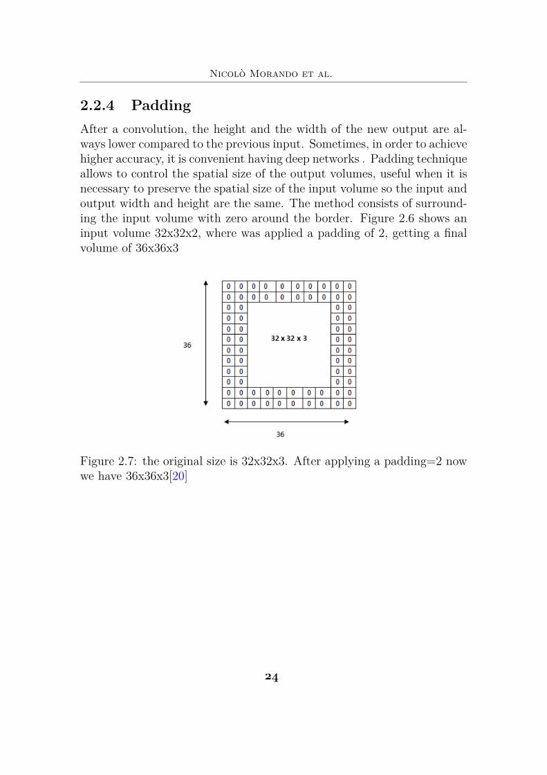
2.2.4 PaddingAfter a convolution, the height and the width of the new output are al-ways lower compared to the previous input. Sometimes, in order to achievehigher accuracy, it is convenient having deep networks . Padding techniqueallows to control the spatial size of the output volumes, useful when it isnecessary to preserve the spatial size of the input volume so the input andoutput width and height are the same. The method consists of surround-ing the input volume with zero around the border. Figure 2.6 shows aninput volume 32x32x2, where was applied a padding of 2, getting a finalvolume of 36x36x3
Figure 2.7: the original size is 32x32x3. After applying a padding=2 nowwe have 36x36x3[20]
"#
2 – Theoretical Background
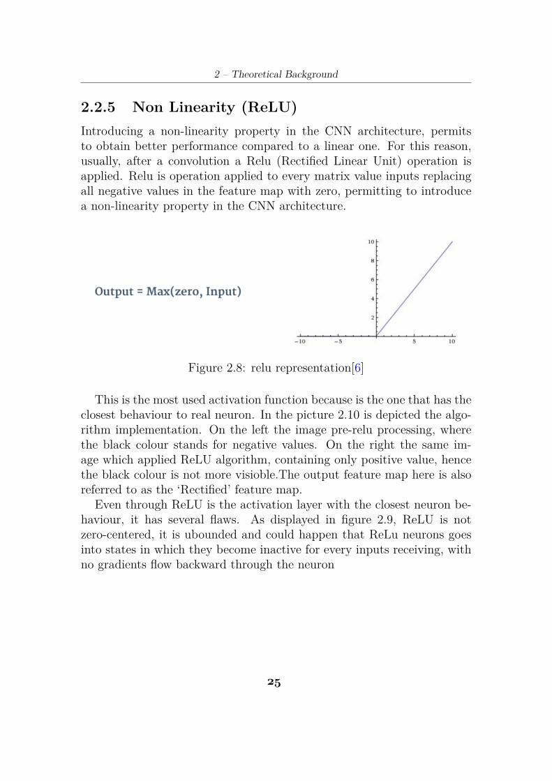
2.2.5 Non Linearity (ReLU)Introducing a non-linearity property in the CNN architecture, permitsto obtain better performance compared to a linear one. For this reason,usually, after a convolution a Relu (Rectified Linear Unit) operation isapplied. Relu is operation applied to every matrix value inputs replacingall negative values in the feature map with zero, permitting to introducea non-linearity property in the CNN architecture.
Figure 2.8: relu representation[6]
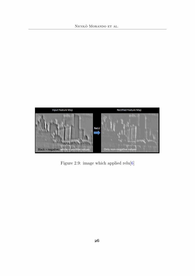
This is the most used activation function because is the one that has theclosest behaviour to real neuron. In the picture 2.10 is depicted the algo-rithm implementation. On the left the image pre-relu processing, wherethe black colour stands for negative values. On the right the same im-age which applied ReLU algorithm, containing only positive value, hencethe black colour is not more visioble.The output feature map here is alsoreferred to as the ‘Rectified’ feature map.
Even through ReLU is the activation layer with the closest neuron be-haviour, it has several flaws. As displayed in figure 2.9, ReLU is notzero-centered, it is ubounded and could happen that ReLu neurons goesinto states in which they become inactive for every inputs receiving, withno gradients flow backward through the neuron
"$
Nicolò Morando et al.
Figure 2.9: image which applied relu[6]
"%
2 – Theoretical Background
2.3 CNN architectureInterested in ANN started almost 80 years ago, after experimental worksstart understanding how mammalian visual cortex works, permitting toscientists to build model similar to biological neural networks.[19]
From this scenario, Convolutional Neural Network raised up. A typicalCNN structure is composed of an input layer handling images for com-putational stages, an output layer that produces the final answer on theclassification task, and several hidden layers where the feature extractiontakes place. Indeed, from a functional perspective, CNNs can be dividedin two main functional regions: feature extraction, and classification. Theformer region is where most computations take place, and it is mainlycomposed of a specific kind of layer: the convolutional (CONV) layer,where several multidimensional matrix-vector multiplications are carriedout between input images (or feature maps) and abstract filters learnedby the CNN itself. Every years differents CNN architectures challenge ina competition each other in order to obtain the highest score prediction.This competition is the ImageNet Large Scale Visual Recognition Chal-lenge (ILSVRC), based on ImageNet project. The ImageNet project isdatabase containing over 14 million images used for training or predictingpatterns for CNN . In the 2011, Before the spreading of CNN, the bestprediction score obtained in a top-5 rank was to 26.2%. The followingyear, AlexNet reached a 15.3% top-5 rank score.
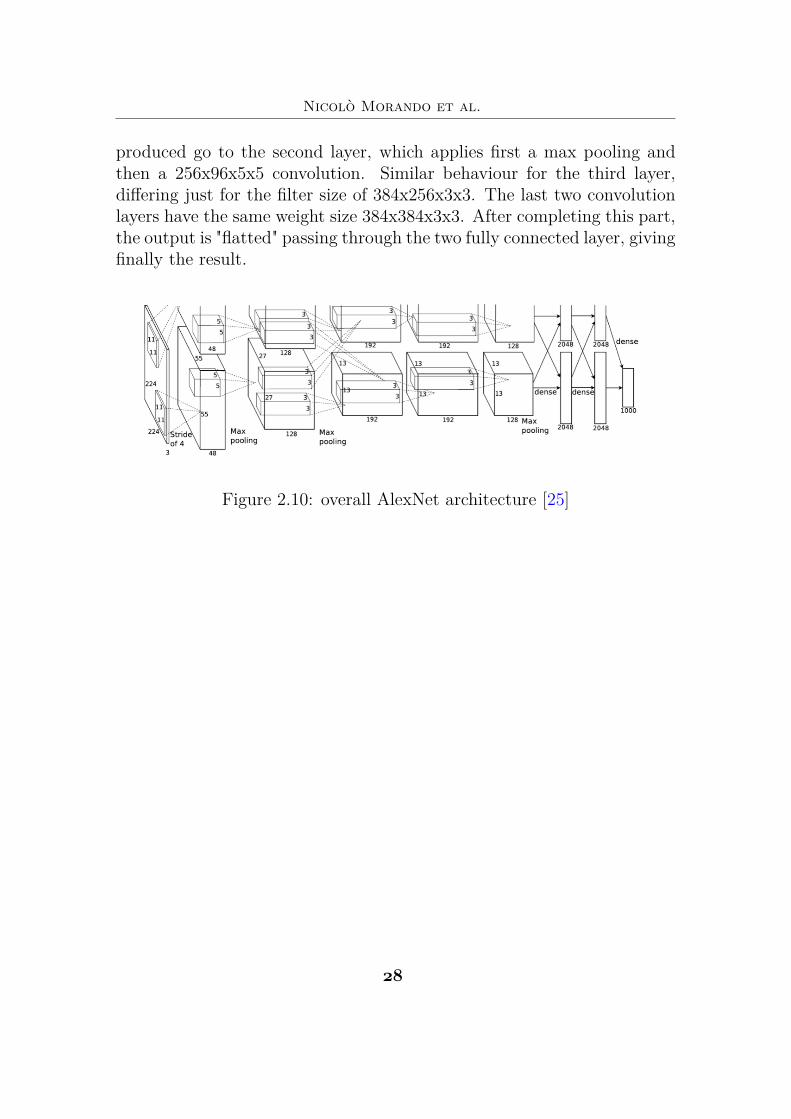
2.3.1 AlexNetAlexNet [25] (fig2.9) is a CNN architecture come into the limelight forbeing the 2012 ImageNet[31] LSVRC-2012 [28] competition winner by alarge margin (15.3% VS 26.2% (second place) top-5 error rates). Thenetwork was trained for 6 days using two GTX 580 3Gb GPUs. It isbased on 5 convolutional layers and 3 fully connected layers. Relu isapplied after every convolutional and fully connected layer and paddinglayer is applied before the first and the second fully connected layer. Thenetwork has 62.3 million parameters, and needs 1.1 billion computationfor completing the whole CNN operations. Convolution layers are only 6%of all operations, but it consumes 95% of the whole computation. Goingin details, figure 2.9 show the overall architecture. The first layer is basedof a convolution with 96 filters 3x11x11 with a stride=4. The outputs
"*
Nicolò Morando et al.
produced go to the second layer, which applies first a max pooling andthen a 256x96x5x5 convolution. Similar behaviour for the third layer,differing just for the filter size of 384x256x3x3. The last two convolutionlayers have the same weight size 384x384x3x3. After completing this part,the output is "flatted" passing through the two fully connected layer, givingfinally the result.
Figure 2.10: overall AlexNet architecture [25]
"&
2 – Theoretical Background
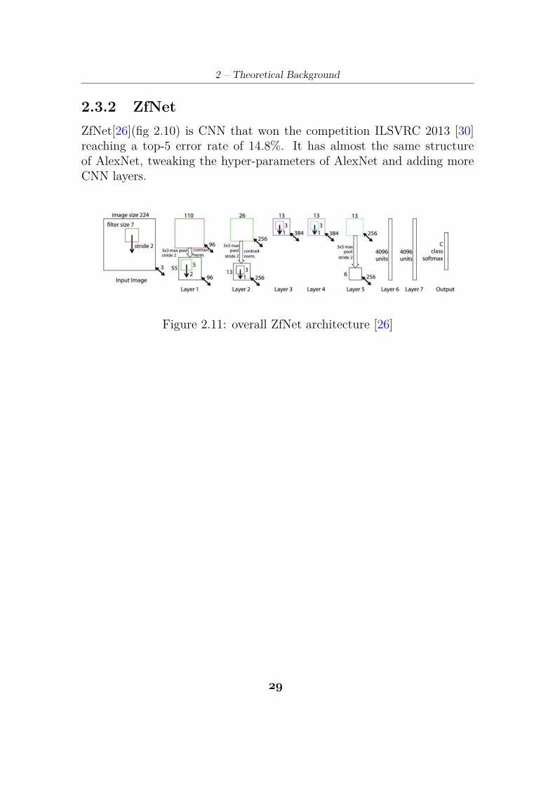
2.3.2 ZfNetZfNet[26](fig 2.10) is CNN that won the competition ILSVRC 2013 [30]reaching a top-5 error rate of 14.8%. It has almost the same structureof AlexNet, tweaking the hyper-parameters of AlexNet and adding moreCNN layers.
Figure 2.11: overall ZfNet architecture [26]
"’
Nicolò Morando et al.
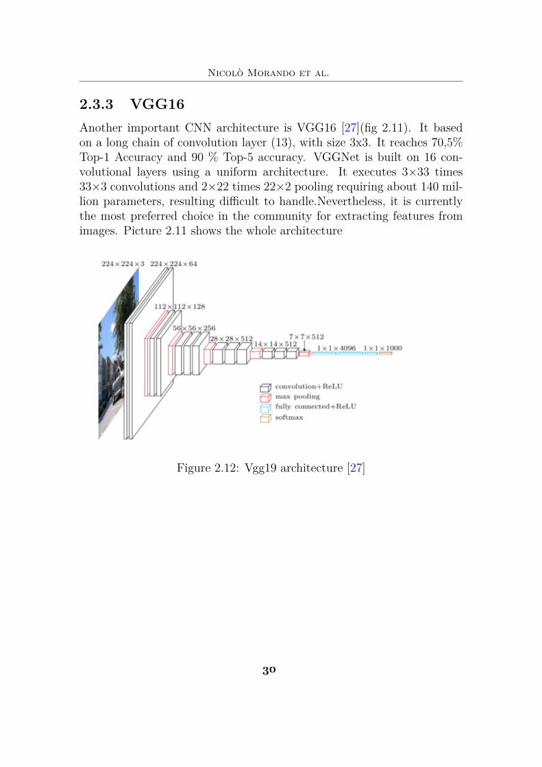
2.3.3 VGG16Another important CNN architecture is VGG16 [27](fig 2.11). It basedon a long chain of convolution layer (13), with size 3x3. It reaches 70,5%Top-1 Accuracy and 90 % Top-5 accuracy. VGGNet is built on 16 con-volutional layers using a uniform architecture. It executes 3◊33 times33◊3 convolutions and 2◊22 times 22◊2 pooling requiring about 140 mil-lion parameters, resulting difficult to handle.Nevertheless, it is currentlythe most preferred choice in the community for extracting features fromimages. Picture 2.11 shows the whole architecture
Figure 2.12: Vgg19 architecture [27]
)(
Chapter 3
Hardware architecturefor CNN
In CNN architecture, accessing in memory off-chip and computing op-erations require considerable execution time. Most of the works mainlyfocus on the computational efficiency of CNNs, without being interestedin memory efficiency of CNNs. Compared to on-chip memory, accessingoff-chip memory can consume up to 10x times power consumption[1], oc-cupying the 30% of the whole execution time for completing a certaintask[10].Consequently, it is difficult integrating CNN algorithms into IoTembedded systems with limited hardware resources. A possible solutioncould be elaborate datas on cloud, but according to CISCO, 5 quintllionbytes of datas are produced every day and by the year 2020, more than 30billion of devices will be connected in internet [2]. So in order to not con-gesting internet traffic, in cloud computing can not be the solution. Datashave to be manipulate locally, but it means execute a significant memorytransaction on/off-chip and viceversa, degrading both power and timingperformance of the system. Considering a traditional system, based onVon Neumann architecture, memory off-chip accesses degrade the overallperformance of the system. The CPU must wait for DRAM data, oftenwasting clock cycle because the operation cannot be executed if not re-ceived the data from off-chip memory. A possible solution could be logicin memory, a memory with some combinational logic associated with eachstorage element. This is an interesting solution, but it’ s still a new tech-nology not tested enough. After having analysed this context carefully, it
")
Nicolò Morando et al.
was opted to reduce memory access via compression algorithm and util-ising systolic paradigms for CNN architecture. In particular was optedto study two architectures: PE CHAIN an MATRIX PE. They’re bothbased on systolic architecture, where the primitive module is the process-ing element (PE).
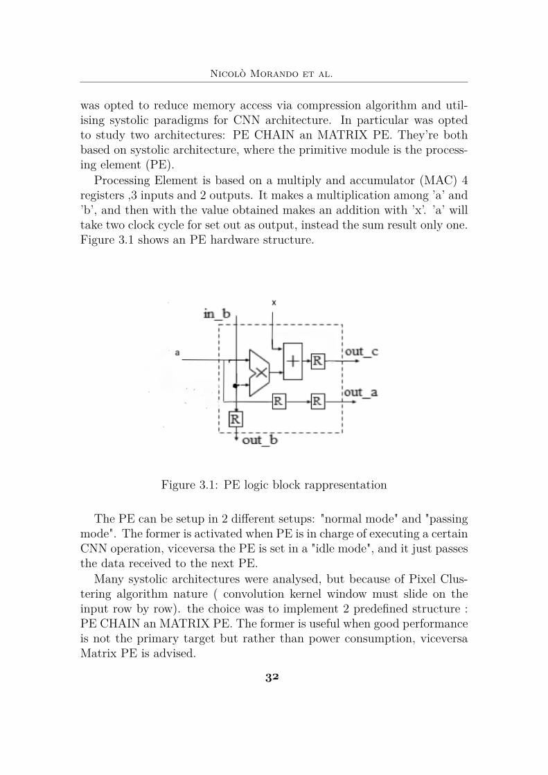
Processing Element is based on a multiply and accumulator (MAC) 4registers ,3 inputs and 2 outputs. It makes a multiplication among ’a’ and’b’, and then with the value obtained makes an addition with ’x’. ’a’ willtake two clock cycle for set out as output, instead the sum result only one.Figure 3.1 shows an PE hardware structure.
Figure 3.1: PE logic block rappresentation
The PE can be setup in 2 different setups: "normal mode" and "passingmode". The former is activated when PE is in charge of executing a certainCNN operation, viceversa the PE is set in a "idle mode", and it just passesthe data received to the next PE.
Many systolic architectures were analysed, but because of Pixel Clus-tering algorithm nature ( convolution kernel window must slide on theinput row by row). the choice was to implement 2 predefined structure :PE CHAIN an MATRIX PE. The former is useful when good performanceis not the primary target but rather than power consumption, viceversaMatrix PE is advised.
)"
3 – Hardware architecture for CNN
3.1 CHAIN PE
Figure 3.2: PE logic block rappresentation[23]
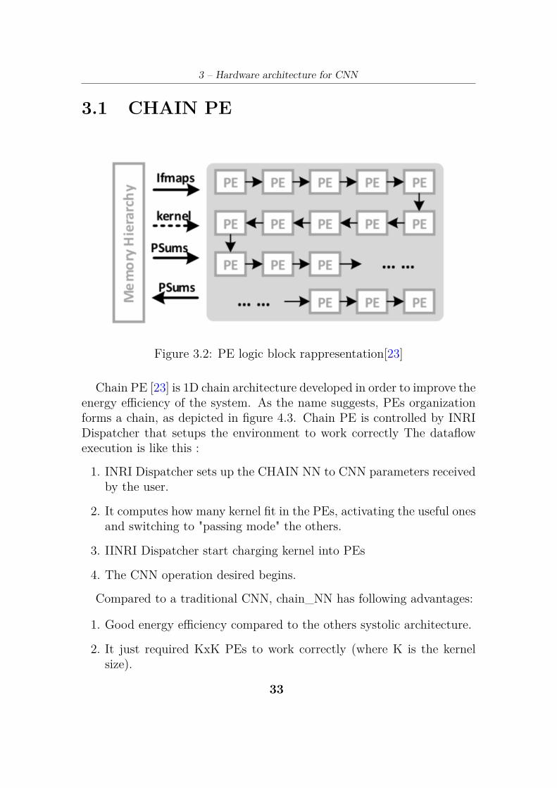
Chain PE [23] is 1D chain architecture developed in order to improve theenergy efficiency of the system. As the name suggests, PEs organizationforms a chain, as depicted in figure 4.3. Chain PE is controlled by INRIDispatcher that setups the environment to work correctly The dataflowexecution is like this :
1. INRI Dispatcher sets up the CHAIN NN to CNN parameters receivedby the user.
2. It computes how many kernel fit in the PEs, activating the useful onesand switching to "passing mode" the others.
3. IINRI Dispatcher start charging kernel into PEs
4. The CNN operation desired begins.
Compared to a traditional CNN, chain_NN has following advantages:
1. Good energy efficiency compared to the others systolic architecture.
2. It just required KxK PEs to work correctly (where K is the kernelsize).
))
Nicolò Morando et al.
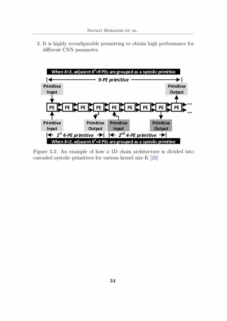
3. It is highly reconfigurable permitting to obtain high performance fordifferent CNN parameter.
Figure 3.3: An example of how a 1D chain architecture is divided intocascaded systolic primitives for various kernel size K [23]
)#

3 – Hardware architecture for CNN
In Fig. 3.3, the PE chain is splitted into 1D primitives according tothe kernel size. The upper side displays when 1D primitive contains 9PEs (K=3) while the lower one K=2. The first PE of the chain receivesthe input from INRI Dispatcher, while the last one send the result to thePixel Clustering module. For this research, it was opted to use a systolicchain composed of 121 PEs. Table 3.1 shows different possible kernel sizecombinations that can be obtained having 121 PEs.
Table 3.1
Kernel size # of PEs primitive # of active primitives # of active PE Efficiency3x3 9 13 117 96%4x4 16 7 112 92 %7x7 49 2 98 81%9x9 81 1 81 66%
11x11 121 1 121 100%
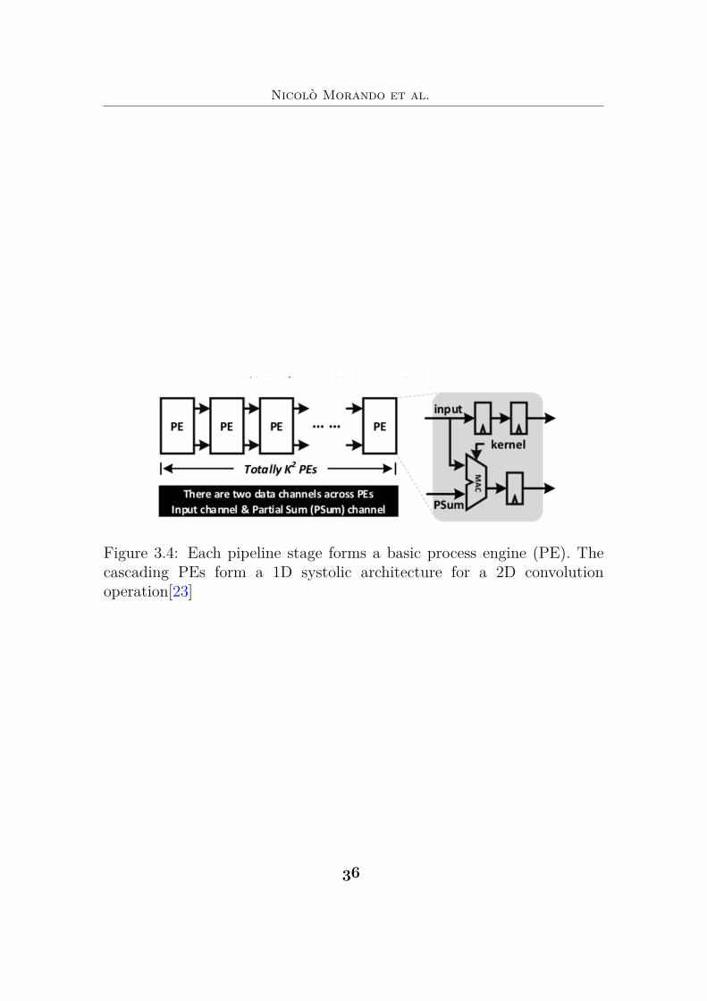
For implementing 1d chain architecture, every primitive for convolu-tions are are represented as 1D implementation.This is obtained usingpipeline technique, forming a chain of multiply-accumulate operations(MAC) depicted in Fig. 4.5 designing a systolic architecture called 1Dsystolic primitive. 1D systolic primitives are based on a group of KxKidentical PEs displayed in Fig. 4(a). The KxK PEs have the same size ofa convolutional kernel window. Every PE, before start the "real" opera-tions, has charged by INRI Dispatcher with a specific kernel weight.
)$
Nicolò Morando et al.
Figure 3.4: Each pipeline stage forms a basic process engine (PE). Thecascading PEs form a 1D systolic architecture for a 2D convolutionoperation[23]
)%
3 – Hardware architecture for CNN
Thus, this type of architecture are able to pass and reused both in-put data and partial sums during convolution, without accessing externalmemory. Meanwhile, it has a fixed input bandwidth requirement and aconstant output delay regardless of the kernel size. Therefore, this 1D sys-tolic primitive can not only decrease the memory accesses, but also can bedesigned according the performance and kernel size desired. Concluding,This architecture is easy to build and implementing , but it presents someflaws. The more the matrix kernel is big and the less inefficient is. infact for example considering a convolution with a matrix kernel 3x3 andstride 1, the 33% of the clock cycle bring useful information. Doing thesame thing, but with a matrix kernel 11x11, only 1 clock cycle to 11 bringuseful information, reducing the efficentess of the system.
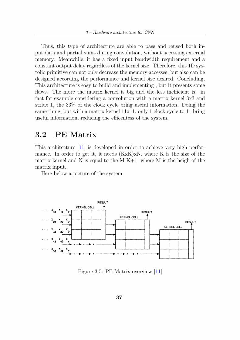
3.2 PE MatrixThis architecture [11] is developed in order to achieve very high perfor-mance. In order to get it, it needs (KxK)xN. where K is the size of thematrix kernel and N is equal to the M-K+1, where M is the heigh of thematrix input.
Here below a picture of the system:
Figure 3.5: PE Matrix overview [11]
)*
Nicolò Morando et al.
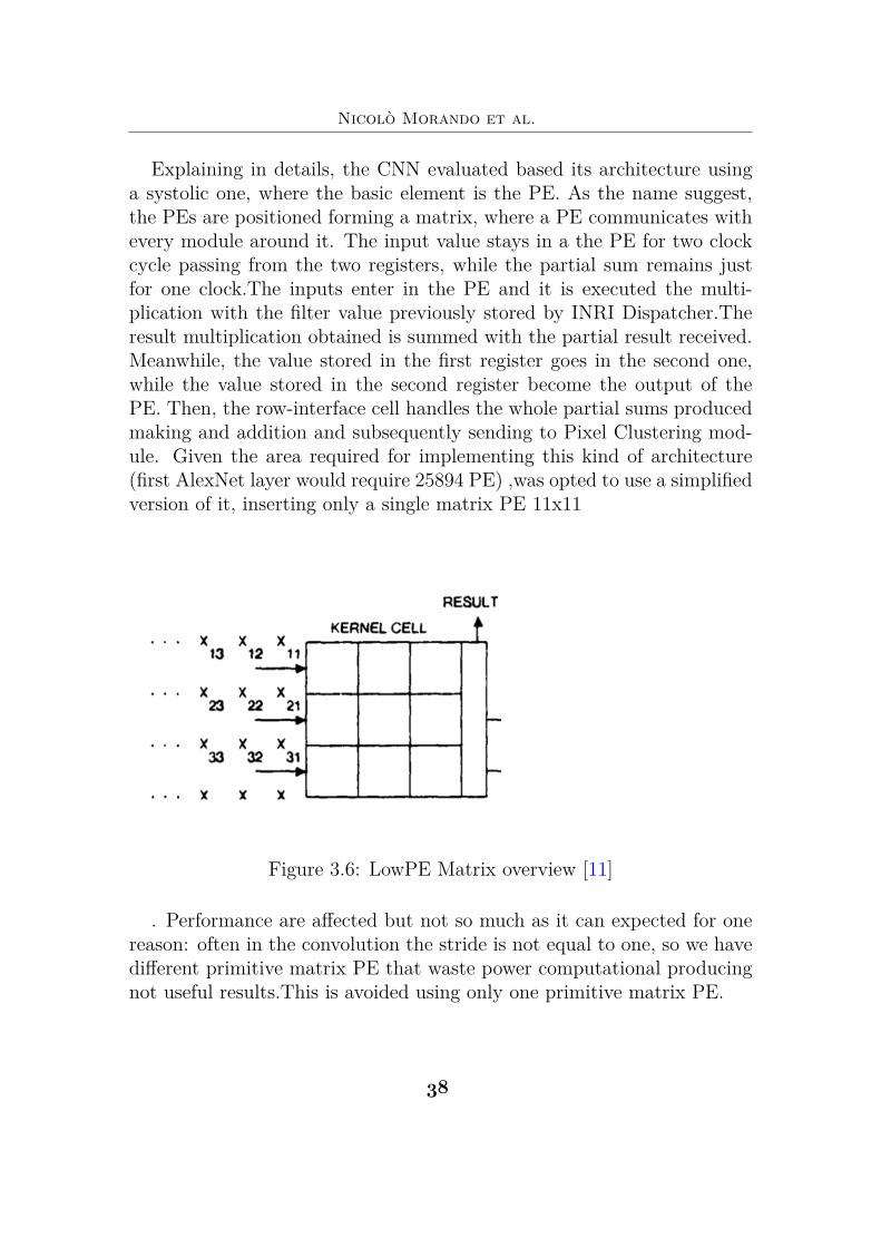
Explaining in details, the CNN evaluated based its architecture usinga systolic one, where the basic element is the PE. As the name suggest,the PEs are positioned forming a matrix, where a PE communicates withevery module around it. The input value stays in a the PE for two clockcycle passing from the two registers, while the partial sum remains justfor one clock.The inputs enter in the PE and it is executed the multi-plication with the filter value previously stored by INRI Dispatcher.Theresult multiplication obtained is summed with the partial result received.Meanwhile, the value stored in the first register goes in the second one,while the value stored in the second register become the output of thePE. Then, the row-interface cell handles the whole partial sums producedmaking and addition and subsequently sending to Pixel Clustering mod-ule. Given the area required for implementing this kind of architecture(first AlexNet layer would require 25894 PE) ,was opted to use a simplifiedversion of it, inserting only a single matrix PE 11x11
Figure 3.6: LowPE Matrix overview [11]
. Performance are affected but not so much as it can expected for onereason: often in the convolution the stride is not equal to one, so we havedifferent primitive matrix PE that waste power computational producingnot useful results.This is avoided using only one primitive matrix PE.
)&
Chapter 4
Hardware softwareco-design for CNNMemory off-chip accesses, are most of the times, the bottleneck of highperforming systems.
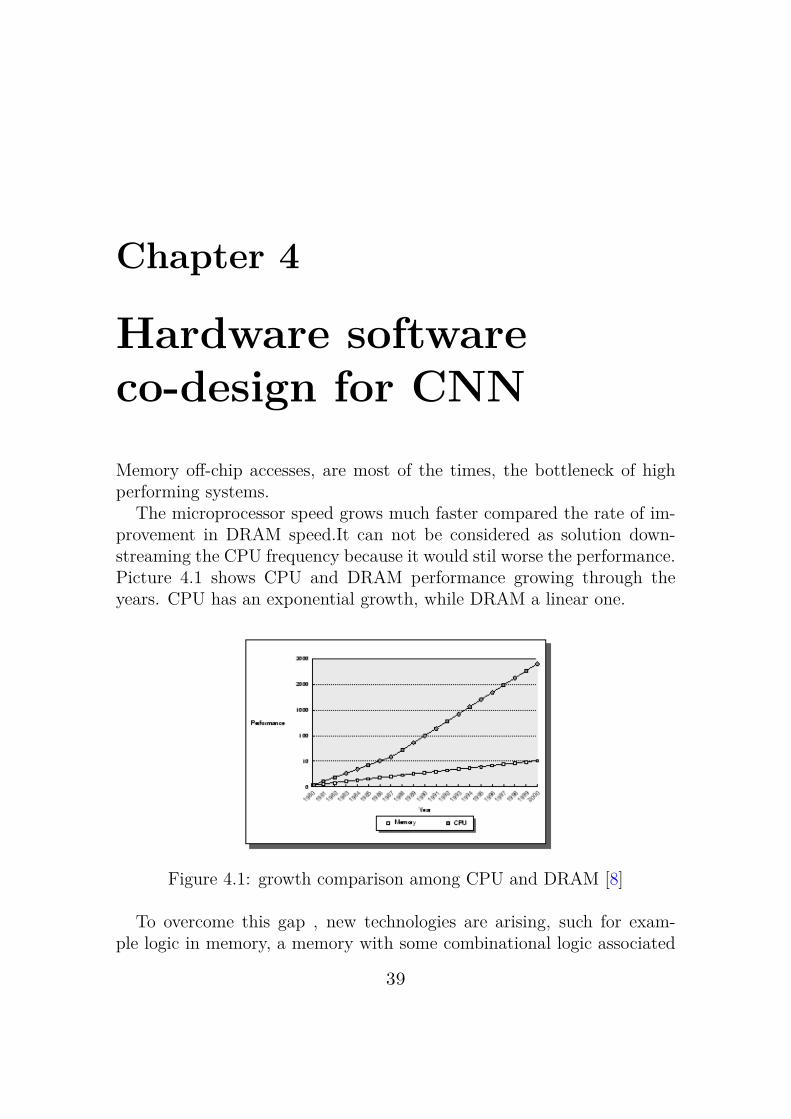
The microprocessor speed grows much faster compared the rate of im-provement in DRAM speed.It can not be considered as solution down-streaming the CPU frequency because it would stil worse the performance.Picture 4.1 shows CPU and DRAM performance growing through theyears. CPU has an exponential growth, while DRAM a linear one.
Figure 4.1: growth comparison among CPU and DRAM [8]
To overcome this gap , new technologies are arising, such for exam-ple logic in memory, a memory with some combinational logic associated
"(
Nicolò Morando et al.
with each storage element. This is an interesting solution, but it is stillan immature technology, and for INRI development was preferred to usetraditional CMOS facilities.
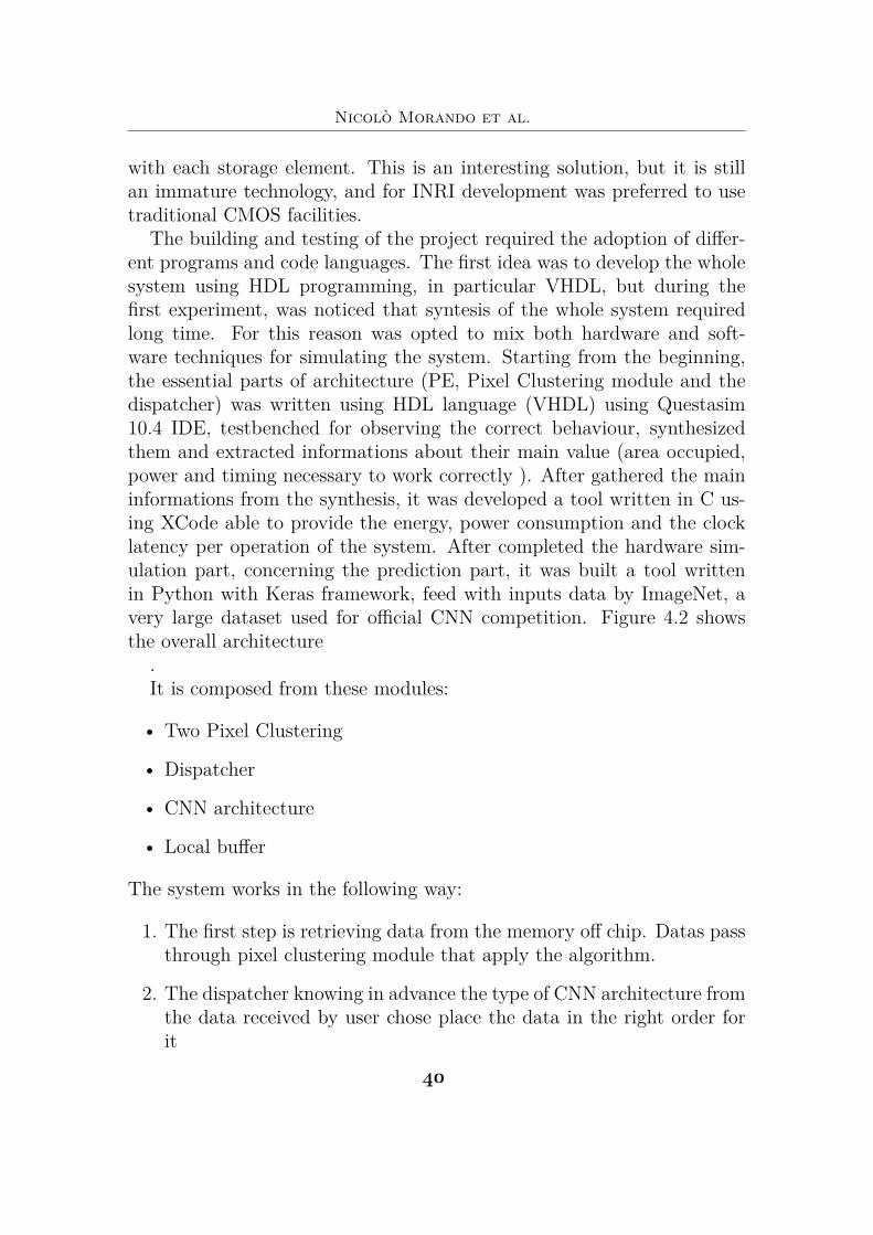
The building and testing of the project required the adoption of differ-ent programs and code languages. The first idea was to develop the wholesystem using HDL programming, in particular VHDL, but during thefirst experiment, was noticed that syntesis of the whole system requiredlong time. For this reason was opted to mix both hardware and soft-ware techniques for simulating the system. Starting from the beginning,the essential parts of architecture (PE, Pixel Clustering module and thedispatcher) was written using HDL language (VHDL) using Questasim10.4 IDE, testbenched for observing the correct behaviour, synthesizedthem and extracted informations about their main value (area occupied,power and timing necessary to work correctly ). After gathered the maininformations from the synthesis, it was developed a tool written in C us-ing XCode able to provide the energy, power consumption and the clocklatency per operation of the system. After completed the hardware sim-ulation part, concerning the prediction part, it was built a tool writtenin Python with Keras framework, feed with inputs data by ImageNet, avery large dataset used for official CNN competition. Figure 4.2 showsthe overall architecture
.It is composed from these modules:
• Two Pixel Clustering
• Dispatcher
• CNN architecture
• Local buffer
The system works in the following way:
1. The first step is retrieving data from the memory off chip. Datas passthrough pixel clustering module that apply the algorithm.
2. The dispatcher knowing in advance the type of CNN architecture fromthe data received by user chose place the data in the right order forit
#(
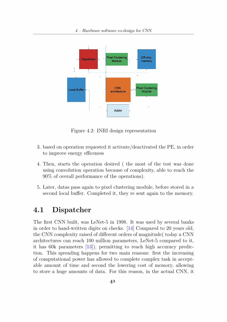
4 – Hardware software co-design for CNN
Figure 4.2: INRI design representation
3. based on operation requested it activate/deactivated the PE, in orderto improve energy efficeness
4. Then, starts the operation desired ( the most of the test was doneusing convolution operation because of complexity, able to reach the90% of overall performance of the operations).
5. Later, datas pass again to pixel clustering module, before stored in asecond local buffer. Completed it, they re sent again to the memory.
4.1 DispatcherThe first CNN built, was LeNet-5 in 1998. It was used by several banksin order to hand-written digits on checks. [14] Compared to 20 years old,the CNN complexity raised of different orders of magnitude( today a CNNarchitectures can reach 100 million parameters, LeNet-5 compared to it,it has 60k parameters [13]), permitting to reach high accuracy predic-tion. This spreading happens for two main reasons: first the increasingof computational power has allowed to complete complex task in accept-able amount of time and second the lowering cost of memory, allowingto store a huge amounts of data. For this reason, in the actual CNN, it
#!
Nicolò Morando et al.
is necessary to implement a module that orchestrates the whole opera-tions. For example, a bad accessing ram management leads to degradethe speed of the system, and if it doesn’t respect the DRAM idle time, itcould provide an unexpected value conducting the operation to return theresult wrong. Another case could be leave activated some modules evenif not used. Considering a PE that just passes information to another PEwithout computing any operation, it will consume the same even throughis not necessary.
Starting from this postulates, it was introduce an hardware dispatcherin the system: INRI Dispatcher. Its duty is to handle the whole op-erations, outlining when read/write in local buffer/memory, which CNNoperation execute, which PE activate and so on.
In order to achieve this enhancement, the Dispatcher is supported by alocal buffer and CNN systolic architecture. Thanks to this optimizzation,is possible to achieve high performance, reducing power consumption.
It was realised using HDL language and simulated developing a tool.
4.1.1 HardwareThe hardware realization, starts with coding the module using VHDL un-der Questa Sim-64 10.6 program. After completing it, was build differentstestbenches for confirming the correct behaviour. Then, it was synthesisedwith CMOS045_SC_14_CORL_LS_bc_1.05V_105C library using de-sign compiler. The INRI Dispatcher ,to set environment correctly, needsto receive two macro groups inputs from user: information about CNNstructure and data to parse. The former is about the number of PEs thatcompose the system, local buffer size, CNN operation desired, filter sizeand the type of CNN architecture chosen, while the latter is the imagewith its size. After gathered all these informations, the dispatcher startsdoing optimizzation, computing how many matrix filters can fit in thePEs, inserting in each of them, the filter values withdrawn from off-chip. then the PEs not exploited for any computation, change their statusin "passing mode", where their duty is only passing the value to the nextPE .Next step, it’s withdraw data inputs from DRAM and place themcorrectly in the local buffer. After setting up the environment, the dis-patcher launches the operation desired and feeds the CNN architecturewith datas. The dispatcher had to know in advance t which clock cyclecontains useful partial sum to store in local buffer or not. These steps are
#"
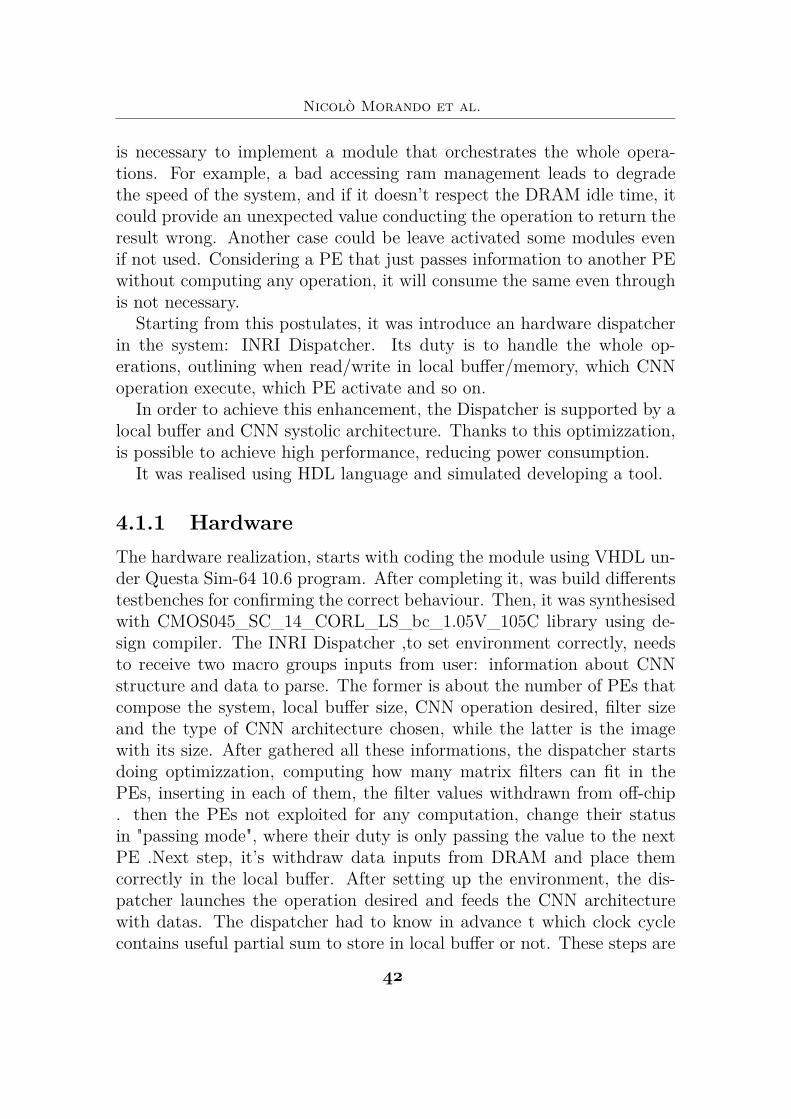
4 – Hardware software co-design for CNN
repeated until the operation is completed. Figure 4.1 shows an example ofconvolution operation. The dispatcher sets the environment charging thefilter value in PEs and stores the input datas inside local buffer.It launchesthe convolution and waits for the right clock for getting the partial valueto store it in the on-chip memory. These steps continue until all filterkernel are parsed
Figure 4.3: example of dispatcher execution flow
4.1.2 SoftwareGiven the complexity of the whole system, it wasn’t possible to synthe-sised it, because it would have required too much time. For this reason, itwas opted to build a simulation tool that returns the main informations(area occupied, power consumed, clock latency for completing an opera-tion an energy ) about architecture. The software is called "Performance
#)
Nicolò Morando et al.
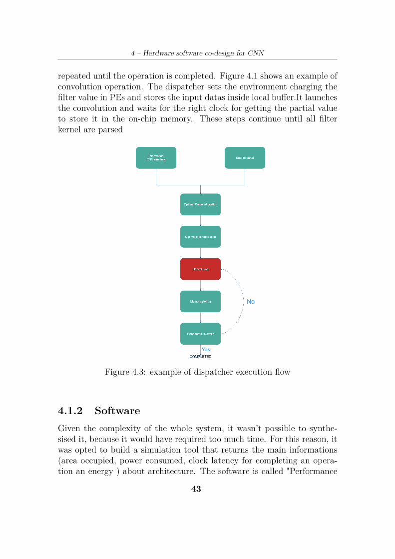
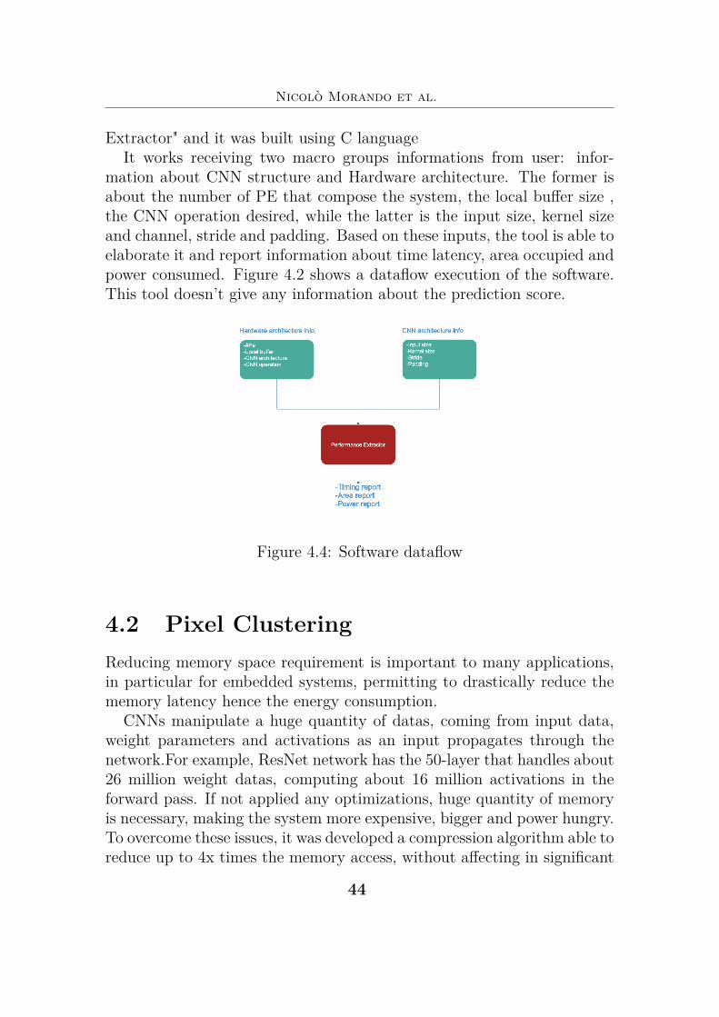
Extractor" and it was built using C languageIt works receiving two macro groups informations from user: infor-
mation about CNN structure and Hardware architecture. The former isabout the number of PE that compose the system, the local buffer size ,the CNN operation desired, while the latter is the input size, kernel sizeand channel, stride and padding. Based on these inputs, the tool is able toelaborate it and report information about time latency, area occupied andpower consumed. Figure 4.2 shows a dataflow execution of the software.This tool doesn’t give any information about the prediction score.
Figure 4.4: Software dataflow
4.2 Pixel ClusteringReducing memory space requirement is important to many applications,in particular for embedded systems, permitting to drastically reduce thememory latency hence the energy consumption.
CNNs manipulate a huge quantity of datas, coming from input data,weight parameters and activations as an input propagates through thenetwork.For example, ResNet network has the 50-layer that handles about26 million weight datas, computing about 16 million activations in theforward pass. If not applied any optimizations, huge quantity of memoryis necessary, making the system more expensive, bigger and power hungry.To overcome these issues, it was developed a compression algorithm able toreduce up to 4x times the memory access, without affecting in significant
##
4 – Hardware software co-design for CNN
way the prediction of the system. The module was produce in hardwareand simulated using Python. It was called "Pixel Clustering". The ideabehind the algorithm is that given an image, the pixels contained in acertain row, the ones close each other , under a certain threshold, have thesame value. Exploiting this postulate developing a tailored architecture, itis possible to drastically reduce the input size, leaving almost unchangedthe image, hence reducing memory access.
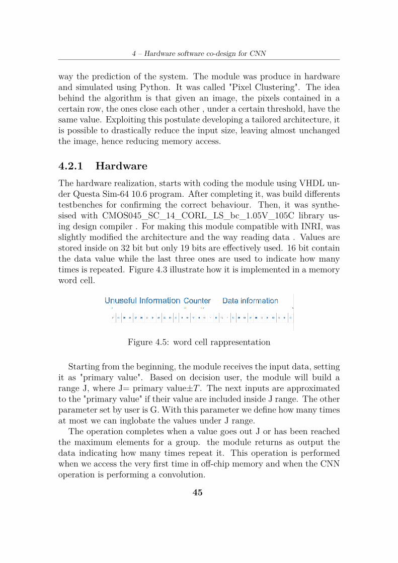
4.2.1 HardwareThe hardware realization, starts with coding the module using VHDL un-der Questa Sim-64 10.6 program. After completing it, was build differentstestbenches for confirming the correct behaviour. Then, it was synthe-sised with CMOS045_SC_14_CORL_LS_bc_1.05V_105C library us-ing design compiler . For making this module compatible with INRI, wasslightly modified the architecture and the way reading data . Values arestored inside on 32 bit but only 19 bits are effectively used. 16 bit containthe data value while the last three ones are used to indicate how manytimes is repeated. Figure 4.3 illustrate how it is implemented in a memoryword cell.
Figure 4.5: word cell rappresentation
Starting from the beginning, the module receives the input data, settingit as "primary value". Based on decision user, the module will build arange J, where J= primary value±T . The next inputs are approximatedto the "primary value" if their value are included inside J range. The otherparameter set by user is G. With this parameter we define how many timesat most we can inglobate the values under J range.
The operation completes when a value goes out J or has been reachedthe maximum elements for a group. the module returns as output thedata indicating how many times repeat it. This operation is performedwhen we access the very first time in off-chip memory and when the CNNoperation is performing a convolution.
#$
Nicolò Morando et al.
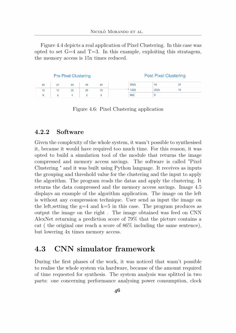
Figure 4.4 depicts a real application of Pixel Clustering. In this case wasopted to set G=4 and T=3. In this example, exploiting this stratagem,the memory access is 15x times reduced.
Figure 4.6: Pixel Clustering application
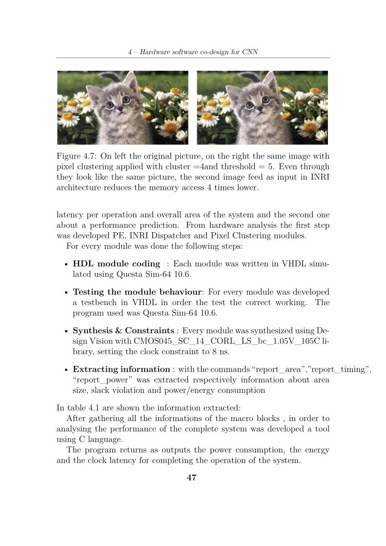
4.2.2 SoftwareGiven the complexity of the whole system, it wasn’t possible to synthesisedit, because it would have required too much time. For this reason, it wasopted to build a simulation tool of the module that returns the imagecompressed and memory access savings. The software is called "PixelClustering " and it was built using Python language. It receives as inputsthe grouping and threshold value for the clustering and the input to applythe algorithm. The program reads the datas and apply the clustering. Itreturns the data compressed and the memory access savings. Image 4.5displays an example of the algorithm application. The image on the leftis without any compression technique. User send as input the image onthe left,setting the g=4 and k=5 in this case. The program produces asoutput the image on the right . The image obtained was feed on CNNAlexNet returning a prediction score of 79% that the picture contains acat ( the original one reach a score of 86% including the same sentence),but lowering 4x times memory access.
4.3 CNN simulator frameworkDuring the first phases of the work, it was noticed that wasn’t possibleto realise the whole system via hardware, because of the amount requiredof time requested for synthesis. The system analysis was splitted in twoparts: one concerning performance analysing power consumption, clock
#%
4 – Hardware software co-design for CNN
Figure 4.7: On left the original picture, on the right the same image withpixel clustering applied with cluster =4and threshold = 5. Even throughthey look like the same picture, the second image feed as input in INRIarchitecture reduces the memory access 4 times lower.
latency per operation and overall area of the system and the second oneabout a performance prediction. From hardware analysis the first stepwas developed PE, INRI Dispatcher and Pixel Clustering modules.
For every module was done the following steps:
• HDL module coding : Each module was written in VHDL simu-lated using Questa Sim-64 10.6.
• Testing the module behaviour: For every module was developeda testbench in VHDL in order the test the correct working. Theprogram used was Questa Sim-64 10.6.
• Synthesis & Constraints : Every module was synthesized using De-sign Vision with CMOS045_SC_14_CORL_LS_bc_1.05V_105C li-brary, setting the clock constraint to 8 ns.
• Extracting information : with the commands “report_area”,”report_timing”,“report_power” was extracted respectively information about areasize, slack violation and power/energy consumption
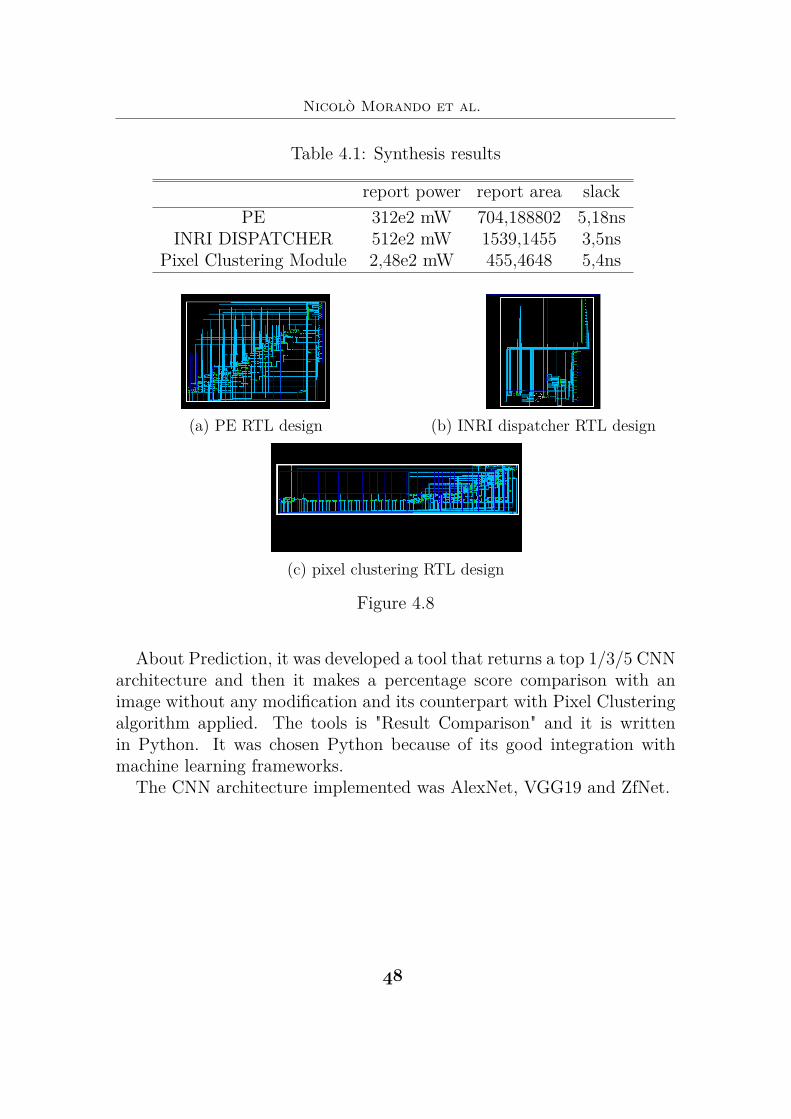
In table 4.1 are shown the information extracted:After gathering all the informations of the macro blocks , in order to
analysing the performance of the complete system was developed a toolusing C language.
The program returns as outputs the power consumption, the energyand the clock latency for completing the operation of the system.
#*
Nicolò Morando et al.
Table 4.1: Synthesis results
report power report area slackPE 312e2 mW 704,188802 5,18ns
INRI DISPATCHER 512e2 mW 1539,1455 3,5nsPixel Clustering Module 2,48e2 mW 455,4648 5,4ns
(a) PE RTL design (b) INRI dispatcher RTL design
(c) pixel clustering RTL design
Figure 4.8
About Prediction, it was developed a tool that returns a top 1/3/5 CNNarchitecture and then it makes a percentage score comparison with animage without any modification and its counterpart with Pixel Clusteringalgorithm applied. The tools is "Result Comparison" and it is writtenin Python. It was chosen Python because of its good integration withmachine learning frameworks.
The CNN architecture implemented was AlexNet, VGG19 and ZfNet.
#&
Chapter 5
Results
5.1 Experimental SetupThe experiments proposed trying to demonstrate the possible performanceimprovements achievable using INRI architecture concerning memory ac-cess, clock latency and power savings without loosing significant percent-age in prediction. The INRI hardware configuration used for the test is256kb local buffer SRAM, 121 PE and 125 Mhz frequency. Summarising,the topics of interest covered with experiments are:
• Memory access
• Accuracy drop
• Prediction score drop
• Power savings
It was analysed both INRI with different setup Pixel Clustering algorithmconfigurations ( grouping values equal to 4,7 and threshold 5,7,15) and tra-ditional system without any reduction technique.Charts results obtainedare an average score among the three CNN architecture VGG16, AlexNetand ZfNet, including all their layers. Completing the part about memo-ry transaction, was investigated the accuracy compared to a traditionalsystem. It was analyse how INRI top1 prediction score differs from atraditional architecture, with same inputs, filter and CNN architecture.The INRI configuration used is grouping values equal 4 and 7 and foreach of them threshold values equal 5,7,15. Terminated it, was also tested
#(
Nicolò Morando et al.
the INRI prediction score. Then was effectuated a test concerning powerconsumption, making an analysis with traditional system and INRI.
5.1.1 Dataset
For testing INRI, the dataset chosen was ImageNet, using more than 10kimage of different randomly classes. ImageNet contains over 14 million ofimages labelled splitted on 20 thousand categories [31]. It was opted tousing these database because is the most used for CNN challenges.
5.1.2 Program languages and frameworks
For the hardware simulation, it was used C language with XCode IDE.Pixel clustering and result comparison was implemented using Python.It was chosen because it’s a very powerful scripting language and it’sextremely supported for machine learning. Concerning about CNN andprediction parts, it was simulated using Keras.
Keras is a powerful framework for Python able to execute some ofthe most famous CNN pre trained architecture model such as VGG-18,GoogleNet, AlexNet. Besides is also possible to build its own CNN archi-tecture. For this reason it was chosen to be used in the CNN implemen-tation.
The Keras installation is the same one for every Operating System, justopen Pyhton terminal and write "pip3 Keras".
5.1.3 Hardware simulation
The code was developed in C language. If you are in a windows environ-ment, it just to double click on the .exe file and execute the program. Ifyou’re under unix open the terminal and through the commands goes tothe folder where the program is placed and launch it. After launching theprogram, it bring you step by step asking you the topology and the maincharacteristic of the system. It gives as output, the power consumption,the energy and the clock latency for completing the operation.
$(
5 – Results
5.1.4 Pixel ClusteringTo set the environment, put the program and the images you want toapply the algorithm on the same folder, just they’re are named with "im-ageXXXX.jpg (where XXXX is a number that goes from 0001 to 9999).
After downloading the program, open the Python shell and goes throughthe folder where there is the program. Launch the program and after theconversion you should have the images converted called "imageXXXXopt.jpg".It also returns the average memory accesses reduction.
5.1.5 Result comparisonPut the program in two folders: the one where is present the imageswithout Pixel Clustering and the one where is applied
Launch the program and it produces a .txt value where, according touser choice, writes the top 1/3/5 prediction score results. (in the foldercontaining image applied Pixel Clustering algorithm the file produce iscalled "opt.txt", while in the other folder is "norm.txt").
The part about the prediction was developed using Keras and its pre-trained model.
5.1.6 Result comparison2After producing the two txt files, put them in folder where is present"result_comparison2.py". It give the percentage of how the two systemsproduce the same prediction.
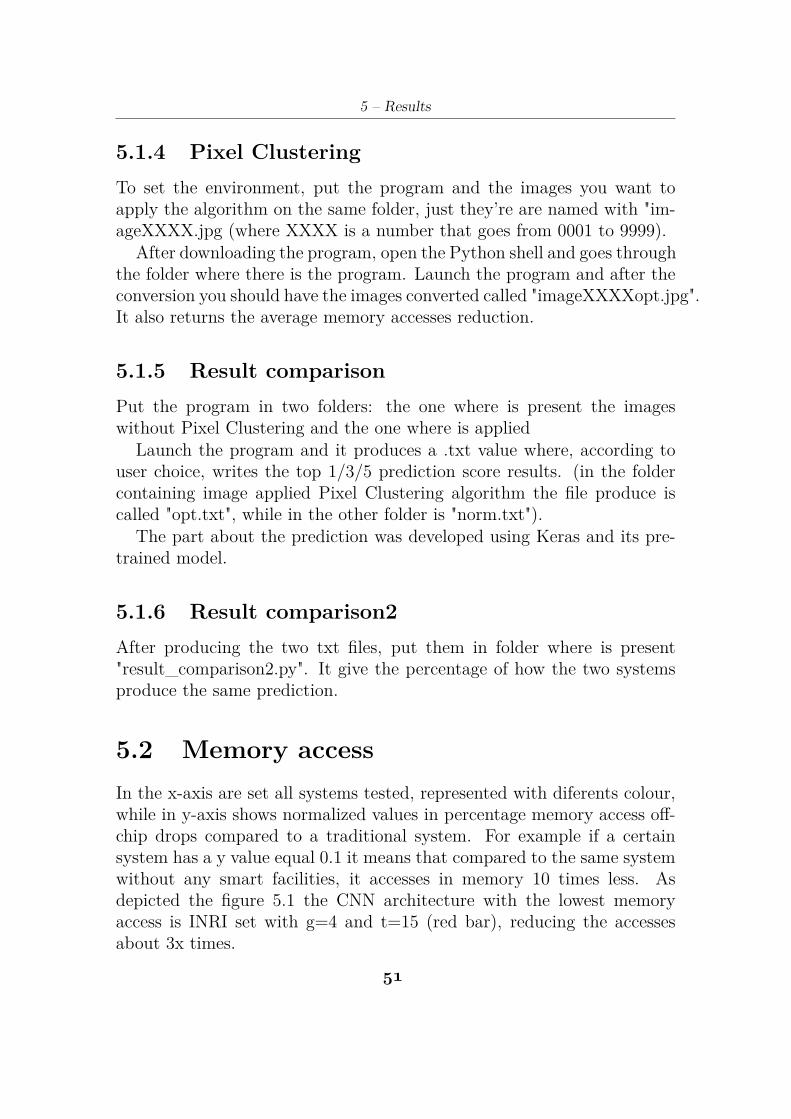
5.2 Memory accessIn the x-axis are set all systems tested, represented with diferents colour,while in y-axis shows normalized values in percentage memory access off-chip drops compared to a traditional system. For example if a certainsystem has a y value equal 0.1 it means that compared to the same systemwithout any smart facilities, it accesses in memory 10 times less. Asdepicted the figure 5.1 the CNN architecture with the lowest memoryaccess is INRI set with g=4 and t=15 (red bar), reducing the accessesabout 3x times.
$!
Nicolò Morando et al.
Figure 5.1
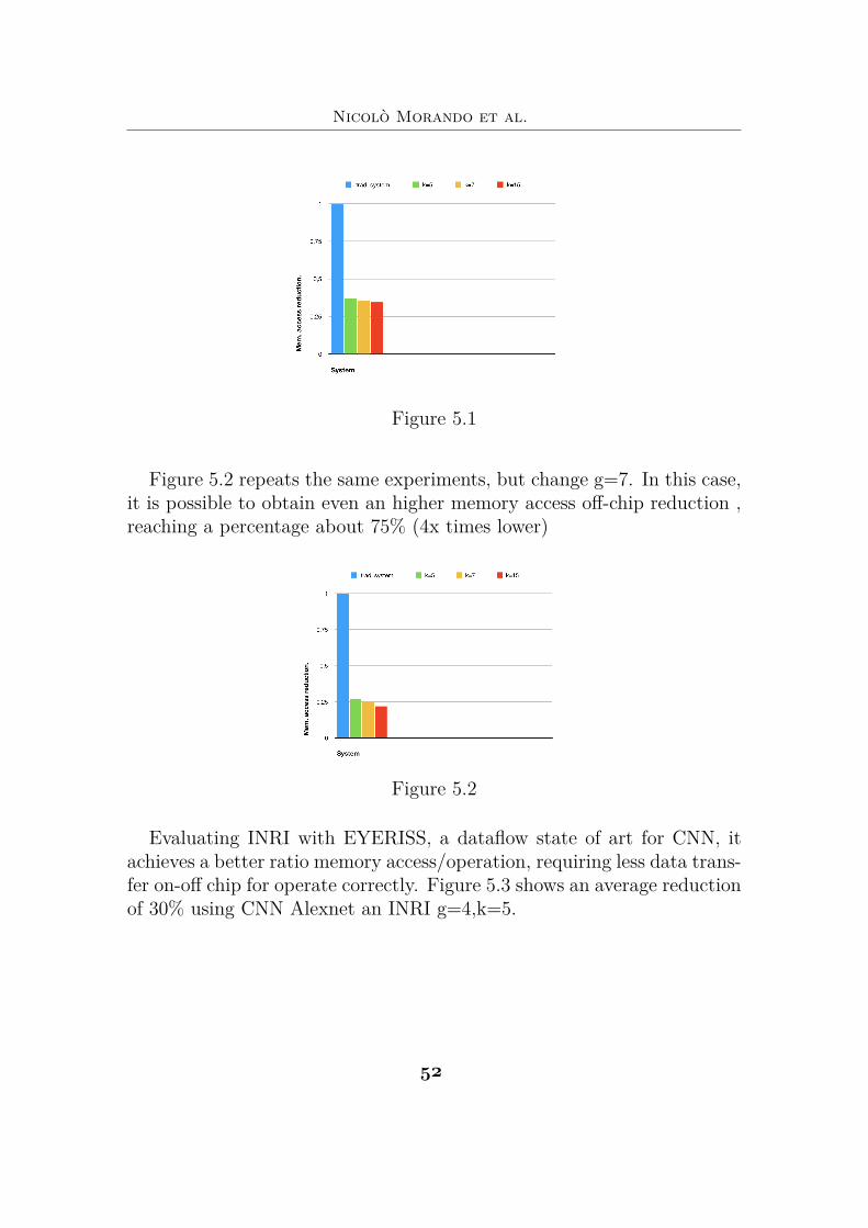
Figure 5.2 repeats the same experiments, but change g=7. In this case,it is possible to obtain even an higher memory access off-chip reduction ,reaching a percentage about 75% (4x times lower)
Figure 5.2
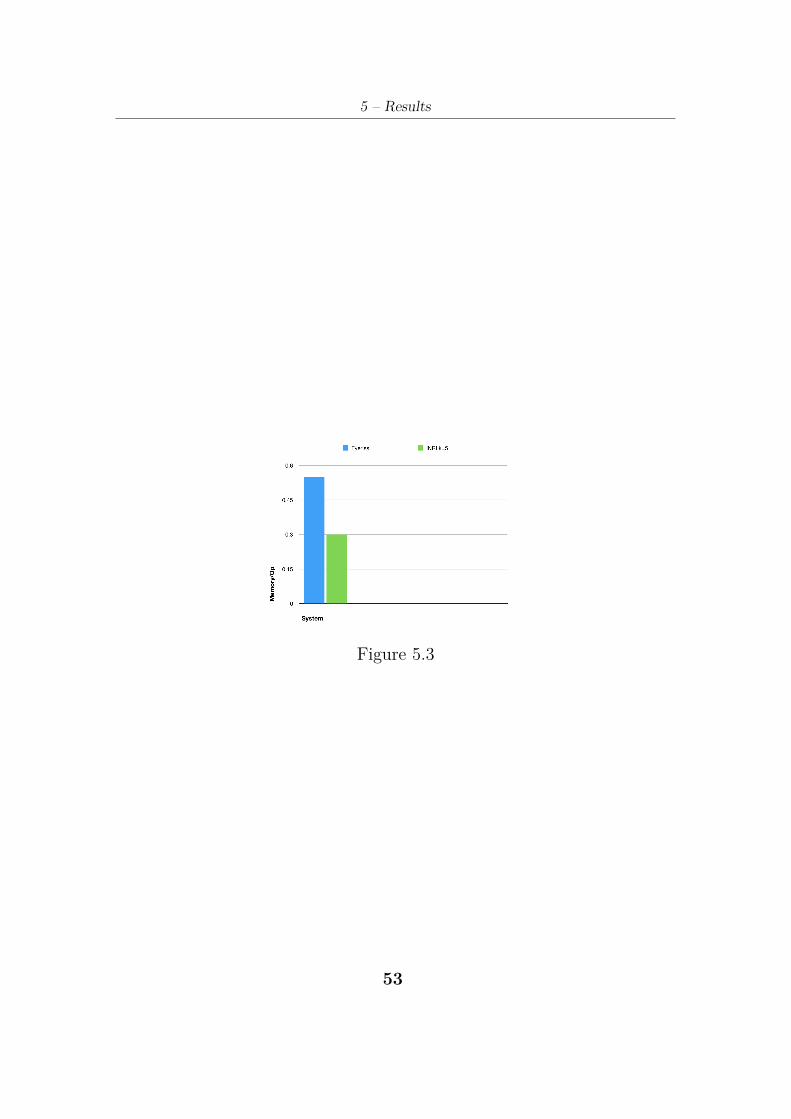
Evaluating INRI with EYERISS, a dataflow state of art for CNN, itachieves a better ratio memory access/operation, requiring less data trans-fer on-off chip for operate correctly. Figure 5.3 shows an average reductionof 30% using CNN Alexnet an INRI g=4,k=5.
$"
5 – Results
Figure 5.3
$)
Nicolò Morando et al.
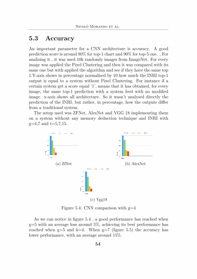
5.3 AccuracyAn important parameter for a CNN architecture is accuracy. A goodprediction score is around 80% for top-1 chart and 90% for top-5 one. , Foranalizing it , it was used 10k randomly images from ImageNet. For everyimage was applied the Pixel Clustering and then it was compared with itssame one but with applied the algorithm and see if they have the same top1.Y-axis shows in percentage normalised by 10 how much the INRI top-1output is equal to a system without Pixel Clustering. For instance if acertain system get a score equal ’1’, means that it has obtained, for everyimage, the same top-1 prediction with a system feed with no modifiedimage. x-axis shows all architecture. So it wasn’t analysed directly theprediction of the INRI, but rather, in percentage, how the outputs differfrom a traditional system.
The setup used was ZFNet, AlexNet and VGG 18 implementing themon a system without any memory deduction technique and INRI withg=4,7 and t=5,7,15.
(a) ZfNet (b) AlexNet
(c) Vgg19
Figure 5.4: CNN comparison with g=4
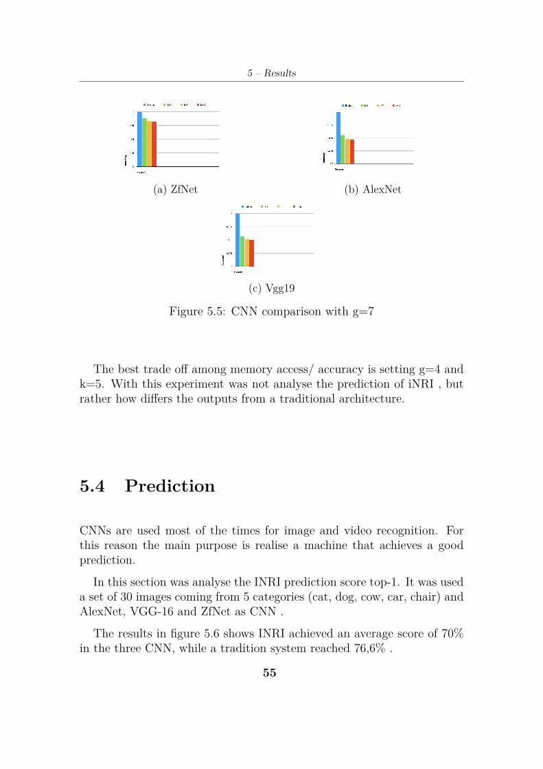
As we can notice in figure 5.4 , a good performance has reached wheng=5 with an average loss around 5%, achieving its best performance hasreached when g=5 and k=4. When g=7 (figure 5.5) the accuracy haslower performance, with an average around 15%.
$#
5 – Results
(a) ZfNet (b) AlexNet
(c) Vgg19
Figure 5.5: CNN comparison with g=7
The best trade off among memory access/ accuracy is setting g=4 andk=5. With this experiment was not analyse the prediction of iNRI , butrather how differs the outputs from a traditional architecture.
5.4 Prediction
CNNs are used most of the times for image and video recognition. Forthis reason the main purpose is realise a machine that achieves a goodprediction.
In this section was analyse the INRI prediction score top-1. It was useda set of 30 images coming from 5 categories (cat, dog, cow, car, chair) andAlexNet, VGG-16 and ZfNet as CNN .
The results in figure 5.6 shows INRI achieved an average score of 70%in the three CNN, while a tradition system reached 76,6% .
$$
Nicolò Morando et al.
5.5 Bottom-up: training and testing a CNNarchitecture with INRI
The tests done until now has demonstrated a significant memory reductionwithout affecting too much performance (above all using INRI with g=5and t= 4 settings), next step was about built a CNN from the bottom,training the system with Pixel Clustering images input and after startingthe predictions.
For this reason was developed a CNN able to recognise if the inputreceived contains was a dog or a cat. The source code is here available
https://github.com/nmorando/realtb/blob/master/thesis/dogcat. For this experiment was trained two networks, one with Pixel Custer-
ing algorithm and the other one without any algorithm. Then for everynetwork was send the same dataset with and without Pixel Clusteringalgorithm. For training the networks was used a dataset containing 1kimage splitted halved for both.
(https://github.com/nmorando/realtb/blob/master/thesis/dogcat.)For the prediction set, was used 100 randomly image of cat or dog( https://github.com/nmorando/realtb/blob/master/thesis/dogcat). Both CNN architecture achieve a score about 90% of accuracy, with-
out any significant different among them.
5.6 Area & power consumptionThe introduction of a dispatcher and a Pixel Clustering bring improve-ments in terms of system performance and memory access, garantueeingreasonable containment in terms of area and power consumption.
The main area is occupied by the PE, followed by the INRI dispatcherand then to the Pixel Clustering Module.
5.6.1 AreaThe overall area occupied by the system (local buffer excluded) is equalto . A single PE size is 7744um2 , but in the system 121 PEs are presents,occupying 937024um2. The whole area occupied is equal to 939473um2.The insertion of a dispatcher and a pixel clustering , occupy in percentage,only the 3,30% total area.
$%
5 – Results
Table 5.1: Area results
total area um2 total area %PE 7744 96,7
INRI DISPATCHER 1539,14 2,78Pixel Clustering Module 455,46 0,52
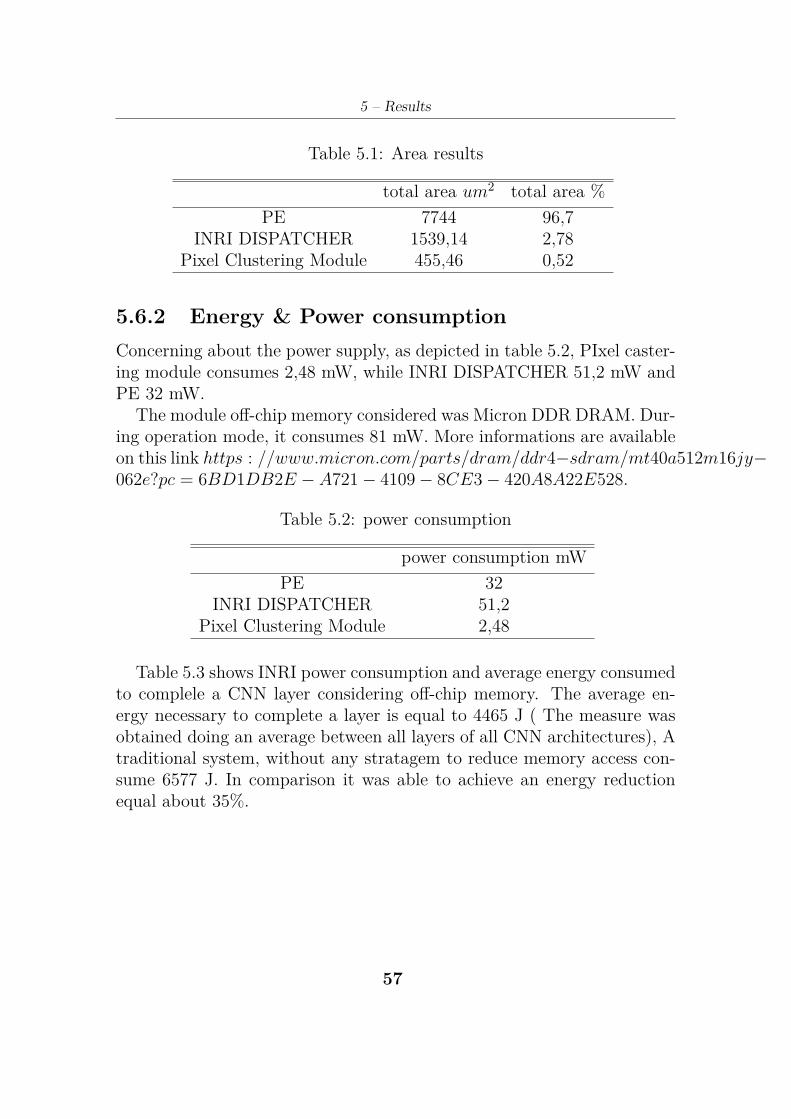
5.6.2 Energy & Power consumptionConcerning about the power supply, as depicted in table 5.2, PIxel caster-ing module consumes 2,48 mW, while INRI DISPATCHER 51,2 mW andPE 32 mW.
The module off-chip memory considered was Micron DDR DRAM. Dur-ing operation mode, it consumes 81 mW. More informations are availableon this link https : //www.micron.com/parts/dram/ddr4≠sdram/mt40a512m16jy≠062e?pc = 6BD1DB2E ≠ A721 ≠ 4109 ≠ 8CE3 ≠ 420A8A22E528.
Table 5.2: power consumption
power consumption mWPE 32
INRI DISPATCHER 51,2Pixel Clustering Module 2,48
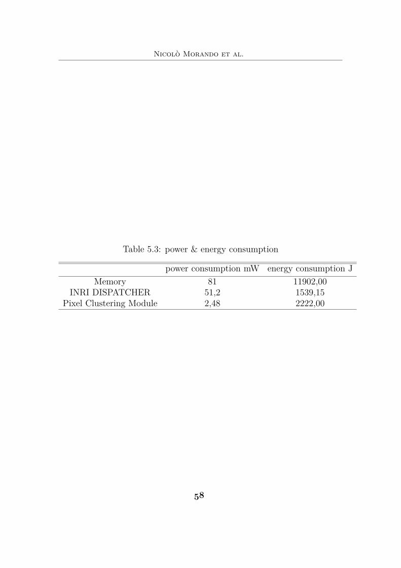
Table 5.3 shows INRI power consumption and average energy consumedto complele a CNN layer considering off-chip memory. The average en-ergy necessary to complete a layer is equal to 4465 J ( The measure wasobtained doing an average between all layers of all CNN architectures), Atraditional system, without any stratagem to reduce memory access con-sume 6577 J. In comparison it was able to achieve an energy reductionequal about 35%.
$*
Nicolò Morando et al.
Table 5.3: power & energy consumption
power consumption mW energy consumption JMemory 81 11902,00
INRI DISPATCHER 51,2 1539,15Pixel Clustering Module 2,48 2222,00
$&
5 – Results
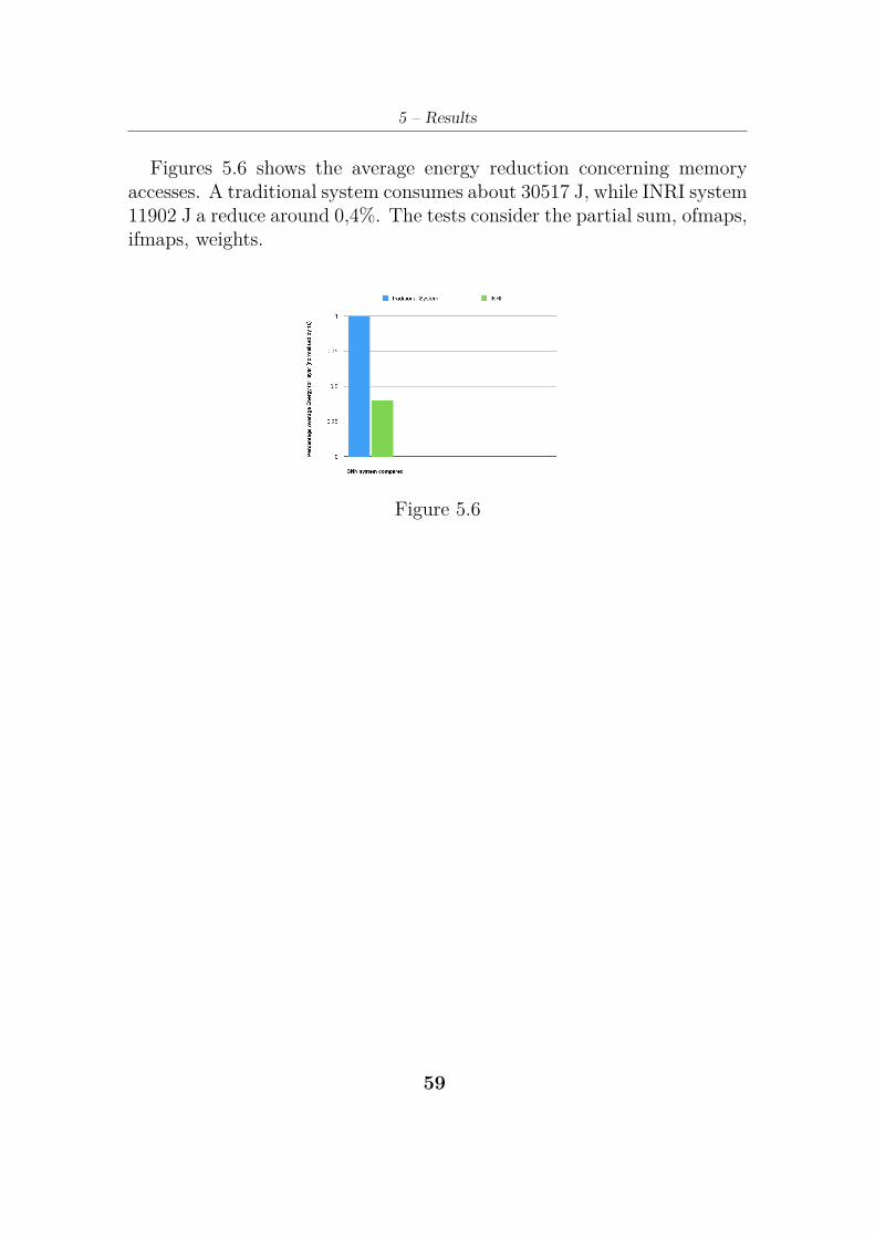
Figures 5.6 shows the average energy reduction concerning memoryaccesses. A traditional system consumes about 30517 J, while INRI system11902 J a reduce around 0,4%. The tests consider the partial sum, ofmaps,ifmaps, weights.
Figure 5.6
$’

%*
Chapter 6
ConclusionCompared to a traditional system, this works demonstrates that imple-menting a systolic architecture and pixel clustering algorithm, is possibleto reduce 3 times memory off-chip reducing up to 70% power consump-tion. This can be useful above all in that system that needs to implementvision recognition, without having high performance system.
Besides was also demonstrate that is possible to train. the networkachieving interesting result. A further step enharced of the system couldbe a better memory management concerning the pixel clustering algo-rithm.
The system implement a SRAM with 32 bit word size cell, but only 19(16 bit contains data,3 bit for algorithm) of them are really use.
An interesting implementation could be reduce the bit data to 8 (dif-ferent studies demonstrate that up to 8 bit, the accuracy of CNN is stillaccettable),testing the performance and so implementing a sram with 16bit word cell.
%)

%!
Chapter 7
FIlesIn https://github.com/nmorando/realtb/blob/master/thesis/pe
are available all files described in the previous chapters, where is pos-sible to download an make every modification in order to make improve-ments.
%"

%#
Bibliography
[1] PREETI RANJAN PANDA ,On-Chip vs. Off-Chip Memory: The DataPartitioning Problem in Embedded Processor-Based Systemsi, 2016
[2] Tim Stack ,Data Center Internet of Things (IoT) Data Continues toExplode Exponentially. Who Is Using That Data and How?, 2018
[3] https://medium.com/@sidereal/cnns-architectures-lenet-alexnet-vgg-googlenet-resnet-and-more-666091488df5,
[4] https://machinelearningmastery.com/supervised-and-unsupervised-machine-learning-algorithms/,
[5] https://www.datascience.com/blog/supervised-and-unsupervised-machine-learning-algorithms /,
[6] https://medium.com/@kanchansarkar/relu-not-a-differentiable-function-why-used-in-gradient-based-optimization-7fef3a4cecec,
[7] Karen Simonyan, Andrew ZissermanVery Deep Convolutional Net-works for Large-Scale Image Recognition, 2015
[8] https://www.extremetech.com/extreme/188776-how-l1-and-l2-cpu-caches-work-and-why-theyre-an-essential-part-of-modern-chips, 2015
[9] Yu-Hsin Chen,Tushar Krishna, Joel Emer, Vivienne Sze,NEyeriss:An Energy-Efficient Reconfigurable Accelerator for Deep ConvolutionalNeural Networksi, 2016
[10] Kevin Kai-Wei Chang, Donghyuk Lee, Zeshan Chishti ,ImprovingDRAM Performance by Parallelizing Refreshes with Accessesi, 2016
[11] Liangzhen Lai,Naveen Suda,Vikas Chandra,Deep Convolutional Neu-ral Network Inference with Floating-point Weights and Fixed-point Ac-tivationsi, 2017
[12] Liangzhen Lai,Naveen Suda,Vikas Chandra,Deep Convolutional Neu-ral Network Inference with Floating-point Weights and Fixed-point Ac-tivationsi, 2017
%$
Nicolò Morando et al.
[13] Shahariar Rabby, https://medium.com/@shahariarrabby/lenet-5-alexnet-vgg-16-from-deeplearning-ai-2a4fa5f26344 , 2017
[14] Yann LeCun,Lèon Bottou,Yoshua Bengio, Patrick Haffner, Gradient-Based learning Applied to Document Recognition , 1998
[15] https://pythonmachinelearning.pro/introduction-to-convolutional-neural-networks-for-vision-tasks , 1998
[16] https://stats.stackexchange.com/questions/269893/2d-convolution-with-depth , 2017
[17] http://cs231n.github.io/convolutional-networks/[18] https://people.inf.ethz.ch/omutlu/pub/VAMPIRE-DRAM-power-
characterization-and-modeling_sigmetrics18-talk.pdf[19] https://pdfs.semanticscholar.org/64db/333bb1b830f937b47d786921af4a6c2b3233.pdf[20] Adi Deshpande,https://adeshpande3.github.io/A-Beginner%27s-
Guide-To-Understanding-Convolutional-Neural-Networks-Part-2/,2010
[21] R. Hameed, W. Qadeer, M. Wachs, O. Azizi, A. Solomatnikov, B.C. Lee, S. Richardson, C. Kozyrakis, and M. Horowitz, UnderstandingSources of Inefficiency in General-purpose Chips, in ISCA, 2010
[22] H.T. Kung, S.W.Song,A Systolic 2-D Convolution Chip, 1981[23] Shihao Wang, Dajiang Zhou, Xushen Han, Takeshi Yoshimura,Chain-
NN: An Energy-Efficient 1D Chain Architecture for Accelerating DeepConvolutional Neural Networks, 2016
[24] S. Arthur,Some Studies in Machine Learning Using the Game ofCheckers , IBM Journal of Research and Development, 1959
[25] Alex Krizhevsky, Ilya Sutskever, Geoffrey E. Hinton,ImageNet Clas-sification with Deep Convolutional Neural Networks , 2012
[26] Matthew D. Zeiler, Rob Fergus,Visualizing and Understanding Con-volutional Networks , 2012
[27] Karen Simonyan, Andrew Zisserman,Very Deep Convolutional Net-works for Large-Scale Image Recognition , 2012
[28] http://www.image-net.org/challenges/LSVRC/2013/results.php#cls,2012
[29] https://towardsdatascience.com/applied-deep-learning-part-1-artificial-neural-networks-d7834f67a4f6, 2017
[30] https://medium.com/coinmonks/paper-review-of-alexnet-caffenet-winner-in-ilsvrc-2012-image-classification-b93598314160
[31] Olga Russakovsky, Jia Deng, Hao Su, Jonathan Krause, Sanjeev
%%
Bibliography
Satheesh, Sean Ma, Zhiheng Huang, Andrej Karpathy, Aditya Khosla,Michael Bernstein, Alexander C. Berg, Li Fei-FeiLarge Scale VisualRecognition Challenge , 2015
%*

%’
Appendix A
image_converter.pyimport cv2
import numpy as npfrom PIL import Imageimport os# read image into matrix.directory = os.fsencode("/home/nicolomorando/Desktop/testset")counter_p=1fc = 0fco = 0for file in os.listdir(directory):filename = os.fsdecode(file)if filename.endswith(".jpg") and filename.find("opt") == -1:if(counter_p<10) :m = cv2.imread("image_000" + str(counter_p) + ".jpg" )
if(counter_p<100) and (counter_p>=10) :m = cv2.imread("image_00" + str(counter_p) + ".jpg" )if(counter_p<1000) and (counter_p>=100):
m = cv2.imread("image_0" + str(counter_p) + ".jpg" )# get image properties.h,w,bpp = np.shape(m)counter=0tmp=0counter_noOpt=0counter_op=0# BLUE = 0, GREEN = 1, RED = 2.
%(
Nicolò Morando et al.
for i in range(0,3):for px in range(0,h):for py in range(0,w):
if(counter==0):tmp=m[px][py][i]
counter_op=counter_op+1if((m[px][py][i]>tmp-5) and (m[px][py][i]<tmp+5)):
m[px][py][i]=tmpcounter=counter+1
else:counter=0
if counter==3:counter=0counter_noOpt=counter_noOpt+1
cv2.imwrite(’img_R-G.jpg’,m)print(counter_op)print(counter_noOpt)
*(
Appendix B
comparison_result.pyfrom keras.preprocessing.image import load_img
from keras.preprocessing.image import img_to_arrayfrom keras.applications.vgg19 import preprocess_inputfrom keras.applications.vgg19 import decode_predictionsfrom keras.applications.vgg19 import VGG19import cv2from time import sleep# load the modelimport os# read image into matrix.files = open("opt.txt","w")directory = os.fsencode("/home/nicolomorando/Desktop/opt")model = VGG19() # AlexNet() ZfNet()counter_p = 1# load an image from filefor file in os.listdir(directory):
filename = os.fsdecode(file)if(counter_p<10) :
image = load_img("image_000" + str(counter_p) +"opt"+".jpg", target_size=(224, 224))
if(counter_p<100) and (counter_p>=10) :image = load_img("image_00" + str(counter_p) + "opt"+
".jpg", target_size=(224, 224))if(counter_p<1000) and (counter_p>=100):
&)
Nicolò Morando et al.
image = load_img("image_0" + str(counter_p) + "opt"+".jpg", target_size=(224, 224))
# convert the image pixels to a numpy arrayimage = img_to_array(image)# reshape data for the modelimage = image.reshape((1, image.shape[0], image.shape[1], im-
age.shape[2]))# prepare the image for the VGG modelimage = preprocess_input(image)# predict the probability across all output classesyhat = model.predict(image)# convert the probabilities to class labelslabel = decode_predictions(yhat)# retrieve the most likely result, e.g. highest probabilitylabel = label[0][0]# print the classification
files.write(label[1]+"n")
*"
Appendix C
comparison_result.pypt2c = 0
ce = 0with open("norm.txt") as f1, open("opt.txt") as f2:
for x, y in zip(f1, f2):x = x.strip()y = y.strip()c+= 1if x==y :
ce+= 1print(ce/c)
&"

&#
Appendix D
performance_extractor#include <stdio.h>
#include <stdlib.h>FILE *f;int n_ram_access=0;float energy_ram_access = 0;float energy_conv =0 ;int clk_ram=0;int clk_tot=0;float energy_tot=0;float pe_energy=0.00000135;float ram_energy=0.228;int stride = 0 ;int padding = 0;int image_size = 0;int kernel_image_depht = 0 ;int kernel_size = 0;int kernel_pack = 0;int pe = 0;int average_mem_access = 0;int local_buffer_size = 0 ;int total_memory_access= 0;float total_number_element=0;int quante_conv_posso_fare = 0;int is_1dd = 0;float how_many_time_i_split=0;
&$
Nicolò Morando et al.
int main(int argc, const char * argv[])f = fopen("info.txt","r");if ( f != NULL )
char line [ 128 ]; /* or other suitable maximum line size */while ( fgets ( line, sizeof line, f) != NULL ) /* read a line */if(f != NULL)
fputs ( stride, atoi(fgets ( line, sizeof line, f) ) );fputs ( padding, atoi(fgets ( line, sizeof line, f) ) );fputs ( image_size, atoi(fgets ( line, sizeof line, f) ) );fputs ( kernel_image_depht, atoi(fgets ( line, sizeof line,
f) ) );fputs ( kernel_size, atoi(fgets ( line, sizeof line, f) ) );fputs ( kernel_pack, atoi(fgets ( line, sizeof line, f) ) );fputs ( average_mem_access, atoi(fgets ( line, sizeof
line, f) ) );fputs ( local_buffer_size, atoi(fgets ( line, sizeof line, f)
) );fputs ( is_1dd, atoi(fgets ( line, sizeof line, f) ) );fputs ( pe, atoi(fgets ( line, sizeof line, f) ) );
fclose ( f );total_number_element = (float)(average_mem_access*image_size*image_size*kernel_image_depht);if (total_number_element>local_buffer_size)
how_many_time_i_split=(float)(total_number_element/local_buffer_size);
if((int)(how_many_time_i_split)==0)n_ram_access= total_number_element + kernel_image_depht*kernel_size*kernel_size*kernel_pack;
elsen_ram_access= total_number_element*kernel_pack+kernel_image_depht*kernel_size*kernel_size*kernel_pack;
quante_conv_posso_fare=pe/(kernel_size*kernel_size);if(is_1dd==0)
clk_tot = (padding*2+image_size-kernel_size)*(kernel_size/quante_conv_posso_fare)*kernel_image_depht*kernel_pack;
*%
D – performance_extractor
if(is_1dd==1)
clk_tot = (padding*2+image_size-kernel_size+kernel_size*kernel_size)*(kernel_size/quante_conv_posso_fare)*kernel_image_depht*kernel_pack;
energy_ram_access = n_ram_access+ram_energy;energy_conv = clk_tot*pe_energy;energy_tot= energy_ram_access+energy_conv;
return 0;
**

&’
Appendix E
Processing_Element.vhdlibrary ieee;
use ieee.std_logic_1164.all;use ieee.std_logic_arith.all;use ieee.std_logic_unsigned.all;entity PE isPort (
clk : in std_logic;rst: in std_logic;a : in std_logic_vector (7 downto 0);b : in std_logic_vector (15 downto 0 );y : out std_logic_vector (15 downto 0);a1: out std_logic_vector(7 downto 0)
);end PE;architecture BEH of pe is
signal reg1 : std_logic_vector(7 downto 0);beginprocess(clk,rst)begin
if(rst=’0’) thenreg1<=a;y<="0000000000000000";a1<=reg1;
elseif(rising_edge(clk)) then
&(
Nicolò Morando et al.
y<=a*reg1+b;reg1<=a;a1<=reg1;
end if;end if;
end process;end beh;
&(
Appendix F
Pixel_Clustering.vhdlibrary ieee;
use ieee.std_logic_1164.all;use ieee.numericstd.ALL;useieee.stdlogicarith.all;useieee.stdlogicunsigned.all;entity pixel_clustering isPort (clk : in std_logic;rst: in std_logic;a : in std_logic_vector (15 downto 0);b : out std_logic_vector (15 downto 0 );th,c: in std_logic_vector( 2 downto 0);write_en : out std_logic);end pixel_clustering;architecture BEH of pixel_clustering issignal th1,counter,counter1 : std_logic_vector(2 downto 0) := "000";signal sel : std_logic_vector(15 downto 0);beginprocess(clk,rst)begin
if(rst=’0’) thenth1<=th;counter<=c;else
’)
Nicolò Morando et al.
if(rising_edge(clk)) thenif((counter1>counter) or (( sel<a+th1 ) and (sel>a-
th1))) thencounter1<=counter1+1;write_en<=’0’;
elseb<=a;
sel<=a;counter1<="000";write_en<=’1’;
end if;end if;
end if;end process;end beh;
&"
Related Documents