Specialists in Punching Shear Reinforcement LinkStudPSR ™ Design Manual to BS8110 LinkStud PSR Limited c/o Brooks Forgings Ltd Doulton Road Cradley Heath West Midlands B64 5QJ Tel: 08456 528 528 www.linkstudpsr.com Version 2.0 January 2018 The specialist team at LinkStudPSR Limited have created this comprehensive Design Manual, to assist Structural Engineers with a detailed explanaon of the calculaons and rules used to detail and specify the LinkStud PSR (Punching Shear Reinforcement) system. This Manual deals exclusively with the correct use of the now withdrawn BS8110 design standard as at January 2018. If you require any further detailed advice regarding the design and detailing of punching shear reinforcement to either the EC2 or BS8110 standards, please do not hesitate to contact our in-house team of experts.

Welcome message from author
This document is posted to help you gain knowledge. Please leave a comment to let me know what you think about it! Share it to your friends and learn new things together.
Transcript
Specialists in Punching Shear ReinforcementLinkStudPSR™
Design Manual to BS8110
LinkStud PSR Limitedc/o Brooks Forgings Ltd
Doulton RoadCradley Heath
West MidlandsB64 5QJ
Tel: 08456 528 528
www.linkstudpsr.com
Version 2.0January 2018
The specialist team at LinkStudPSR Limited have created this comprehensive Design Manual, to assist Structural Engineers with a detailed explanation of the calculations and rules used to detail and specify the LinkStud PSR (Punching Shear Reinforcement) system.
This Manual deals exclusively with the correct use of the now withdrawn BS8110 design standard as at January 2018.
If you require any further detailed advice regarding the design and detailing of punching shear reinforcement to either the EC2 or BS8110 standards, please do not hesitate to contact our in-house team of experts.
CONTENTS Design Manual to BS8110 Introduction…………………………………………………………… 3 BS8110 Design Preface …………………………………..………... 4 Information required when designing to BS8110 ..................... 5 Introduction to BS8110 design and symbols used …….……... 6 Outline of the BS8110 design process ...................................... 7 Design perimeters and steel areas ............................................. 8 Detailing LinkStuds BS8110 General detailing rules .................................................. 9 Typical LinkStudPSR BS8110 layouts …………………………... 10 Standard LinkStudPSR BS8110 installation details ….…..…... 11 Bottom up installation method ..……………………………. 11 Top down installation method ..…………………………….. 11 Laying out the LinkStudPSR system to BS8110……...……….. 12 Introduction to BS8110 design worked examples ............................ 13 Square or circular loaded areas Internal condition ……………………………………………... 14 Edge condition ………………………………………………… 16 External corner condition ……………………………………. 18 Internal corner condition …………………………………….. 20 Rectangular loaded areas Internal condition ……………………………………………… 22 Edge condition ………………………………………………… 24 External corner condition ……………………………………. 26 Internal corner condition …………………………………….. 28 BS8110 Design guidance for large loaded areas or walls ........ 30 BS8110 Design guidance for holes through the slab …………. 31 BS8110 Design guidance for split level slabs Edge condition ………………………………………………… 32 Internal condition Slab depth change within the loaded area zone ...... 33 Slab depth change outside the loaded area zone … 34 Notes ………………………………………………………………………..... 35
Design Manual to BS8110 January 2018
LinkStudPSR Limited Tel/Fax: 08456 528 528 e-mail: [email protected] web: www.linkstudpsr.com Page 2

Introduction The LinkStudPSR System offers customers a fast, easy and extremely cost effective
method of providing Punching Shear Reinforcement around columns, and piles with-
in flat slabs and post-tensioned slabs, at slab to shearwall junctions, beam to col-
umn junctions and within footings and foundation slabs. The LinkStudPSR System comprises short lengths of carbon steel deformed bar
reinforcement with end anchorages provided by enlarged, hot forged heads at both
ends, giving a cross-sectional area ratio of 9:1. These stud heads anchor securely
in the slab, eliminating slippage and providing greater resistance to punching shear. The double-headed LinkStud shear studs are welded to carrier / spacer rails to allow
them to be located correctly and to be supported by the top flexural reinforcement. LinkStudPSR is a technologically advanced and proven system, the first fully
tested, fully accredited, fully traceable Punching Shear Reinforcement System
approved by CARES for use in reinforced concrete slabs designed in accord-
ance with both EC2 and BS8110 design standards. Through our total focus on Punching Shear Reinforcement we have become experts
in our field, with unparalleled experience in the design of PSR schemes and a
thorough knowledge of the intricacies and complexities of the Eurocode 2 and
BS8110 design standards. We are pleased to be able to offer you this expertise, as
a cornerstone of the LinkStudPSR package. From application advice and design guidance, through proposal drawings,
calculations and quotations, to working drawings and site support, you can depend
on LinkStudPSR for all your Punching Shear Reinforcement needs.
Kind Regards Dariusz Nowik MSc (Eng) Senior Design Engineer
LinkStudPSR Limited
LinkStudPSR Limited Tel/Fax: 08456 528 528 e-mail: [email protected] web: www.linkstudpsr.com Page 3

Design Manual to BS8110
BS8110 Design Preface Please note that the LinkStudPSR design and optimum pattern / layout details can
be calculated very simply, by using the free LinkStudPSR design software (available
later in 2010) with the minimum of input. This design manual simply explains the
methods used to produce the design programme’s output, and although the BS8110
design standard is no longer officially supported, acts as an updatable guide to
display some of the more complex layouts that may not be available within the
LinkStudPSR Design Programme.
If in any doubt, LinkStudPSR’s specialist in-house Engineers can check and
produce calculations and layouts for the Project Engineer’s approval. Although no
longer current, our experienced Designers have access to specialist design
programmes and calculations that can be used to achieve a quicker solution, than
doing traditional long hand calculations and layouts.
To ensure clarity and conformity, this manual and related design procedures
work strictly within the guidelines of the now withdrawn BS8110 part 1. An
orthogonal pattern is used and the minimum required steel sectional area is
calculated at each perimeter from the loaded area (column / pile) face.
Although further design procedures may be incorporated within the EC2 design
standard at a later date as they become more widely accepted, LinkStudPSR
Limited have, for now, focused primarily on improving the quality, traceability,
conformity and certification of the LinkStudPSR system and its availability within the
UK. This is so that the additional studs required to fully comply with the guidelines of
the BS8110 standard can be used, without the increased costs, environmental
impact and complications of importing from overseas.
BS
811
0 D
esig
n P
refa
ce
LinkStudPSR Limited Tel/Fax: 08456 528 528 e-mail: [email protected] web: www.linkstudpsr.com Page 4

LinkStudPSR Limited Tel/Fax: 08456 528 528 e-mail: [email protected] web: www.linkstudpsr.com Page 5
Design Manual to BS8110
De
sig
nin
g to
BS
811
0 -
Info
rma
tio
n r
eq
uire
d
If you would like the punching shear specialists at LinkStudPSR to produce an accurate calculation using
the LinkStudPSR design programme, please copy and complete the pro-forma at the back of this manual
and Fax to 08456 528 528 or forward it to [email protected]. We will need detailed information on:
■ The dimensions and shape of the loaded area (e.g. square, rectangular or circular) ■ The distance of the loaded area from the nearest edge(s) of the slab ■ The diameter and spacing of the top reinforcement bars (bottom if a transfer slab) ■ The depth of the slab ■ The depth of the top and bottom reinforcement cover ■ The characteristic compressive cube strength of the concrete (fcu) ■ The applied design shear load (Vt or Veff) ■ Any design moments applied
Plus - where appropriate
■ The dimensions and position in relation to the loaded area of any holes through the slab ■ Any changes in slab depth, levels or movement joints within the live perimeter (a general
layout drawing may be required) Alternatively, you may prefer to gather the relevant data and produce a calculation and design layout
yourself using the LinkStudPSR on-line design software (available later in 2010) or by using the long hand
calculations to BS8110 that we have laid out later in this manual.
Information required when designing to BS8110
NOTE: It is assumed that: ■ Any loads given by the Project Engineer have been factored using the BS8110 load factors ■ The concrete slab is not constructed using lightweight aggregate
IMPORTANT: Make sure that loads given are only the slab loads and do not include the columns / loaded areas above.
Symbols Units Description a mm Width of loaded area
Asv mm2/m Area of shear reinforcement
b mm Breadth of loaded area
c mm Dimension to edge of slab from face of loaded area (see diagrams)
d mm Effective depth of slab
h mm Overall slab depth
e mm Dimension to edge of slab from face of loaded area (see diagrams)
fcu N/mm2 Characteristic compressive cube strength of concrete at 28 days
fyv N/mm2 Characteristic strength of shear reinforcement. (not to be taken more than 500 N/mm
2)
Mt kN/m Design moment transferred between slab and loaded area at the connection
u0 mm Effective length of the loaded area perimeter
u1, u2…. mm Effective length of the design perimeters
un mm The effective perimeter where v ≤ vc
v N/mm2 Design shear stress
vc N/mm2 Design concrete shear stress
Veff kN Design effective shear including allowance for moment transfer
Vt kN Design shear transferred to loaded area
X mm The length of the side of the perimeter considered parallel to the axis of bending Note: X is always taken as the length of the side of u1 at 1.5d from the loaded area face for each perimeter.
When calculating the direct shear with a moment at the loaded area face, X can be calculated as the length of the side of u0 as a worst case, but it is normal practice to use 1.5d as stated.
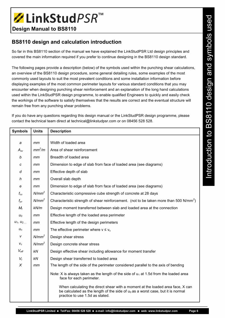
BS8110 design and calculation introduction So far in this BS8110 section of the manual we have explained the LinkStudPSR Ltd design principles and
covered the main information required if you prefer to continue designing in the BS8110 design standard. The following pages provide a description (below) of the symbols used within the punching shear calculations,
an overview of the BS8110 design procedure, some general detailing rules, some examples of the most
commonly used layouts to suit the most prevalent conditions and some installation information before
displaying examples of the most common perimeter layouts for various standard conditions that you may
encounter when designing punching shear reinforcement and an explanation of the long hand calculations
used within the LinkStudPSR design programme, to enable qualified Engineers to quickly and easily check
the workings of the software to satisfy themselves that the results are correct and the eventual structure will
remain free from any punching shear problems. If you do have any questions regarding this design manual or the LinkStudPSR design programme, please
contact the technical team direct at [email protected] or on 08456 528 528.
LinkStudPSR Limited Tel/Fax: 08456 528 528 e-mail: [email protected] web: www.linkstudpsr.com Page 6
Design Manual to BS8110
Intr
od
uctio
n to
BS
811
0 d
esig
n a
nd
sym
bo
ls u
se
d

At un - (perimeter n) check if the punching shear stress is two times greater than the concrete shear capacity without reinforcement Check if v > 2vc
NO YES
LinkStudPSR Limited Tel/Fax: 08456 528 528 e-mail: [email protected] web: www.linkstudpsr.com Page 7
Design Manual to BS8110
Ou
tlin
e o
f th
e B
S8
11
0 d
esig
n p
rocess
Outline of the BS8110 design process
Calculate (vc) concrete shear capacity without reinforcement
The design process for the now withdrawn BS8110 design standard works slightly differently to that used in
the new EC2 (BS EN 1992-1-1:2004) standard, and so we have laid out a simple overview of the steps re-
quired so that a simple comparison can be made between the two standards. NOTE: Please remember to take into account the size and position of any holes / penetrations through the
slab within 6d of the loaded area (see page 79 for further information)
Calculate the required Asw (shear reinforcement) for n perimeter
Check if the punching shear stress at the loaded area face (v) exceeds 0.8 √fcu or 5 N / mm
2
NO YES
FAILURE
n - current perimeter number n = 1
FAILURE
At un - (perimeter n) check if the punching shear stress is less than the concrete shear capacity without reinforcement Check if v < vc
NO YES
Go to next perimeter n = n + 1
Is n > 1
NO YES
No shear reinforcement required
Detail the position of the LinkStuds taking into account the calculated area of reinforcement, spacing rules, shape and position of the loaded area

Design perimeters and steel areas The LinkStudPSR design programme and the traditional BS8110 method, calculates the minimum required steel area needed at each perimeter from the loaded area (column / pile) face. The first perimeter u1 is set at 1.5d from the face and subsequent perimeters are at 0.75d outwards u2, u3 etc. until the slab and reinforcement properties are able to take the shear stresses (vc > v).
Within the first perimeter (u1) there are two boundaries of reinforcement (studs), with the first one at 0.5d from the face, which must provide at least 40% of the required steel area at u1, and the second boundary at 1.25d (0.5d + 0.75d). The first steel area is calculated using the reinforcement within the u1 perimeter, using the studs on the perimeters at 0.5d and 1.25d… with the second area using the studs at 1.25d and 2.0d, and so on.
For example:
LinkStudPSR Limited Tel/Fax: 08456 528 528 e-mail: [email protected] web: www.linkstudpsr.com Page 8
Design Manual to BS8110
De
sig
n p
erim
ete
rs a
nd
ste
el a
reas
0.5d 8 8 studs
u1 8 + 16 = 24 studs
u2 16 + 24 = 40 studs
u3 24 + 32 = 56 studs
u4 no studs required
Stud diameter (mm)
Stud area (mm
2)
10 78.54
12 113.09
14 153.93
16 201.06
20 314.16

LinkStudPSR BS8110 General detailing rules d = effective depth
■ The rail length is calculated so that the start of the rail is in line with the loaded area / column face ■ The distance to the first and last studs on the rail must be at a maximum of 0.5d from the end of the
rail ■ Spacing between the studs along the rail must be at a maximum of 0.75d ■ The forged ends of the studs must capture the top and bottom slab reinforcement ■ The plan dimension between studs around the line of the perimeter must not exceed 1.5d ■ Stud lengths and spacing should be rounded down to the nearest 10 mm
■ Ideally layouts should be symmetrical (see plan details further on in this manual) ■ LinkStuds have a minimum of two and a maximum of eight studs on a rail
Generally, using the above rules simplifies the amount of variation on site and during manufacture, reducing the need for complicated marking systems and the number of drawings required.
Variations should then be limited to only the diameter and number of LinkStuds on a rail.
Mark number “12-4-250-910” = stud diameter – number of studs – length of studs – length of rail The above ‘mark number’ is sufficient information to manufacture and identify the LinkStudPSR system. Each LinkStudPSR rail is manufactured with the correct number of studs required to achieve the design layout, normally providing one rail type per column / pile head and hence no complicated assembly is needed on site. Calculating the rail spacing required can be done without difficulty from the mark number given: i.e. from the above rail “12-4-250-910” : - length of rail = 910 mm & number of studs = 4 Effective slab depth d = length of rail / ( (number of studs – 1) x 0.75 + 1)
for example = 910 / ( ( 4 –1) x 0.75 + 1) = 280 mm effective slab depth Edge spacing = 0.5d = 0.5 x 280 = 140 mm Stud spacing = 0.75d = 0.75 x 280 = 210 mm
LinkStudPSR Limited Tel/Fax: 08456 528 528 e-mail: [email protected] web: www.linkstudpsr.com Page 9
Design Manual to BS8110
BS
811
0 G
ene
ral d
eta
ilin
g r
ule
s
25012 mm diameter
140 210 210 210 140

Internal condition Square loaded area
Rectangular loaded area
Circular loaded area
Edge condition Square loaded area
Rectangular loaded area
Circular loaded area
External corner condition Square loaded area
Rectangular loaded area
Circular loaded area
Internal corner condition
Square loaded area
Rectangular loaded area
Circular loaded area
Typical LinkStudPSR BS8110 layouts
LinkStudPSR Limited Tel/Fax: 08456 528 528 e-mail: [email protected] web: www.linkstudpsr.com Page 10
Design Manual to BS8110
Typ
ica
l L
inkS
tud
BS
811
0 la
yo
uts
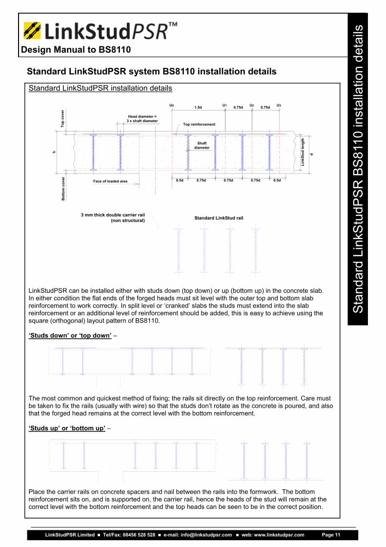
Standard LinkStudPSR installation details LinkStudPSR can be installed either with studs down (top down) or up (bottom up) in the concrete slab. In either condition the flat ends of the forged heads must sit level with the outer top and bottom slab reinforcement to work correctly. In split level or ‘cranked’ slabs the studs must extend into the slab reinforcement or an additional level of reinforcement should be added, this is easy to achieve using the square (orthogonal) layout pattern of BS8110.
‘Studs down’ or ‘top down’ –
The most common and quickest method of fixing; the rails sit directly on the top reinforcement. Care must be taken to fix the rails (usually with wire) so that the studs don’t rotate as the concrete is poured, and also that the forged head remains at the correct level with the bottom reinforcement. ‘Studs up’ or ‘bottom up’ –
Place the carrier rails on concrete spacers and nail between the rails into the formwork. The bottom reinforcement sits on, and is supported on, the carrier rail, hence the heads of the stud will remain at the correct level with the bottom reinforcement and the top heads can be seen to be in the correct position.
Standard LinkStudPSR system BS8110 installation details
LinkStudPSR Limited Tel/Fax: 08456 528 528 e-mail: [email protected] web: www.linkstudpsr.com Page 11
Design Manual to BS8110
Sta
nd
ard
Lin
kS
tud
PS
R B
S8
11
0 insta
llatio
n d
eta
ils
3 mm thick double carrier rail(non structural) Standard LinkStud rail
0.5d 0.75d 0.75d 0.75d 0.5dFace of loaded area
Shaftdiameter
Head diameter =3 x shaft diameter
Top reinforcement
1.5d 0.75d 0.75dU0 U1 U2 U3
d
Link
Stud
leng
th
Top
cove
rB
otto
m c
over
h

Laying out the LinkStudPSR system to BS8110 To simplify the system layout the LinkStudPSR system uses only one ‘symmetrical’ rail type.
In the BS8110 standard the layout patterns are the same for square and circular loaded areas alike.
Large columns may require additional side rails to maintain the maximum distance between the studs of 1.5d.
The carrier / spacer rails are non-structural and can therefore be placed on the top or under the bottom reinforcement.
The LinkStudPSR system rails are manufactured so that they are symmetrical and therefore cannot be installed the wrong way around.
The forged ends (heads) of the studs must remain level with the top and bottom reinforcement layers.
Internal condition layout – installation / pattern creation.
Place the side rails first with the end of the rails touching the load-ed area face. The first stud along the rail should be no more than 0.5d from the loaded area face.
Line up the ends of the outer rails with the loaded area face and the outer stud of the side rails. Then place the inner rails inline with each stud on the side rails, au-tomatically giving the relevant de-signed spacing.
Place the remaining two rails in line with the centre of the column at equal spacing from the two inner rails to complete the pattern, and making sure that the distance to the studs on the inner rails does not exceed 1.5d.
LinkStudPSR Limited Tel/Fax: 08456 528 528 e-mail: [email protected] web: www.linkstudpsr.com Page 12
Design Manual to BS8110
La
yin
g o
ut L
inkS
tud
PS
R to
BS
811
0

LinkStudPSR Limited Tel/Fax: 08456 528 528 e-mail: [email protected] web: www.linkstudpsr.com Page 13
Design Manual to BS8110
Intr
od
uctio
n to
BS
811
0 d
esig
n s
tan
dard
wo
rke
d e
xam
ple
s
As a quick reference guide to the now withdrawn BS8110 design standard, and to help with a like for
like comparison with the new EC2 standard, we have produced a series of layout drawings and
associated long hand calculations for each of the main column types and the most common positions
(conditions) that they are likely to be used in.
We hope that this will help to accelerate the calculation and design process for the most frequently
used conditions.
The following section provides information on designing punching shear reinforcement based strictly
on the orthogonal pattern layout of BS8110. For additional information (not included in this design
manual) on designing using this layout style, please contact the LinkStudPSR technical team.
If you have any questions regarding these calculations or their associated layouts, please do not hes-
itate to contact our technical team on 08456 528 528 or by e-mail at [email protected].
The following pages supply designs and calculations for:
■ Square / circular loaded areas - Internal condition ............................. p.62-63
■ Square / circular loaded areas - Edge condition ................................. p.64-65
■ Square / circular loaded areas - External corner condition .................. p.66-67
■ Square / circular loaded areas - Internal corner condition ................... p.68-69
■ Rectangular loaded areas - Internal condition ..................................... p.70-71
■ Rectangular loaded areas - Edge condition ........................................ p.72-73
■ Rectangular loaded areas - External corner condition ........................ p.74-75
■ Rectangular loaded areas - Internal corner condition ......................... p.76-77

Square loaded area - Internal condition
Circular loaded area - Internal condition
LinkStudPSR Limited Tel/Fax: 08456 528 528 e-mail: [email protected] web: www.linkstudpsr.com Page 14
Design Manual to BS8110
Sq
ua
re / C
ircu
lar
load
ed
are
as -
INT
ER
NA
L

Reference to BS8110 part 1 d = h – top cover – T1 Bars size / 2 – T2 Bars size / 2 (average in both directions)
x = a + ( 2 x 1.5d ) (required only when there is a moment in the slab)
u0 = 4a (Square loaded area) or aπ (Circular loaded area)
Veff = 1.15Vt (direct shear) or Veff = Vt ( 1 + 1.5Mt / (Vt x X) ) (moment present) v = Veff / ( u0 x d )
Check ‘v’ is not greater than 0.8 x √fcu or 5 N/mm²
fcu should not to be taken greater than 40 N/mm²
Figure 3.14
3.7.7.2
Figure 3.15 Design at face
Equation 27
3.7.6.4 & 3.7.7.2
Design each perimeter u1, u2, …un - starting 1.5d from the loaded area face and at 0.75d thereafter until vc is greater than or equal to v. u1 = ( ( 1.5d x 2) + a ) x 4 ….u2 = ( ( 2.25d x 2) + a ) x 4 … u3 = ( ( 3d x 2) + a ) x 4 … & so on
vc = 0.79 x ( ( ( 100As / ( 1000 x d ) )1/3
x ( 400 / d )1/4
) / 1.25 ) x (fcu / 25)1/3
Where:
100As / ( 1000 x d ) ≤ 3 400 / d ≥ 1
v = Veff / ( u1 x d )
Design at perimeters 3.7.7.3
Table 3.8
Equation 28
v < vc
v > 2vc
v ≤ 1.6vc
1.6vc < v ≤ 2vc
■ No Shear reinforcement is required
■ Redesign using: deeper slab, increased grade or top reinforcement.
■ Asv = (v – vc ) u1 d / ( 0.87fyv ) Note: Sin 90º = 1 for vertical bars
■ Asv = 5 (0.7 v – vc ) u1 d / ( 0.87fyv ) Note: Sin 90º = 1 for vertical bars
3.7.7.4
3.7.7.5
Equation 29a
Equation 29b
Check against minimum steel = ( 0.4 u1 d ) / ( 0.87fyv ) …. (altering u1 to u2 , etc…accordingly)
Note: Asv is for TWO perimeters of studs / links at a maximum of 0.75d centres. The first perimeter of studs located at 0.5d should contain at least 40% of the calculated area of the reinforcement required in u1.
Repeat ‘design at perimeters’… until v < vc hence no more reinforcement is required.
Figure 3.17
Square / Circular loaded areas - INTERNAL
LinkStudPSR Limited Tel/Fax: 08456 528 528 e-mail: [email protected] web: www.linkstudpsr.com Page 15
Design Manual to BS8110
Sq
ua
re / C
ircu
lar
load
ed
are
as -
INT
ER
NA
L
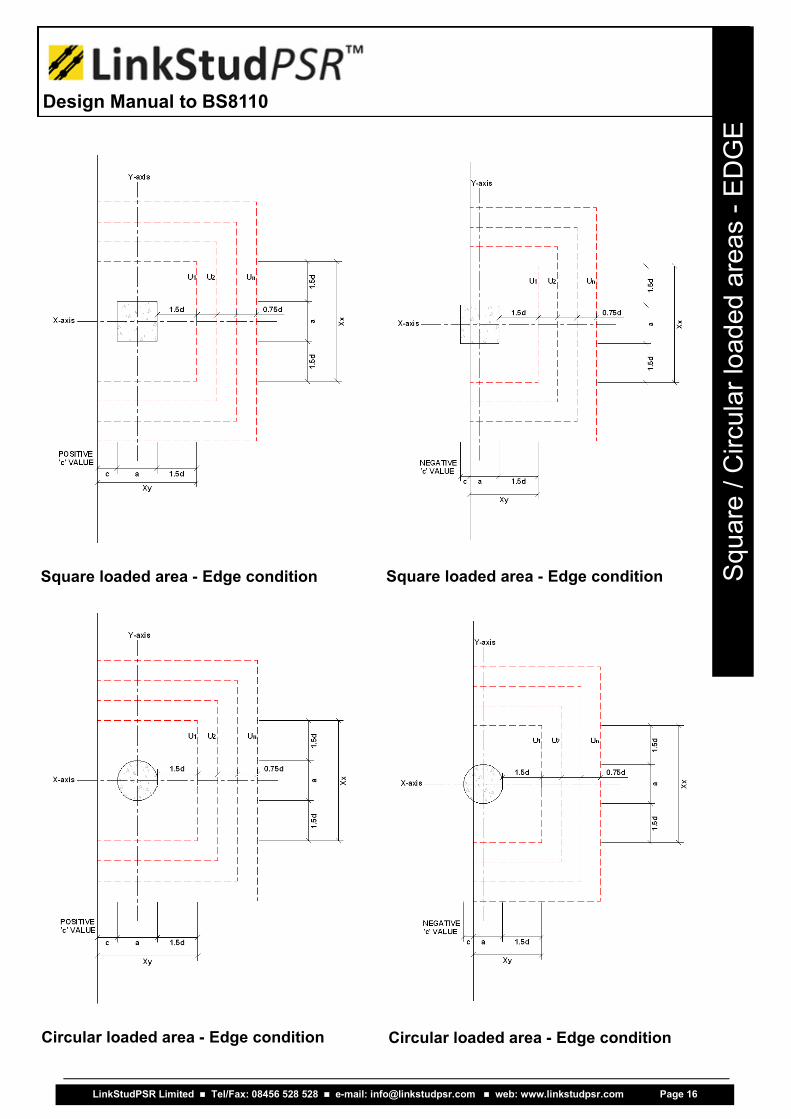
Square loaded area - Edge condition Square loaded area - Edge condition
Circular loaded area - Edge condition Circular loaded area - Edge condition
LinkStudPSR Limited Tel/Fax: 08456 528 528 e-mail: [email protected] web: www.linkstudpsr.com Page 16
Design Manual to BS8110
Sq
ua
re / C
ircu
lar
load
ed
are
as -
ED
GE
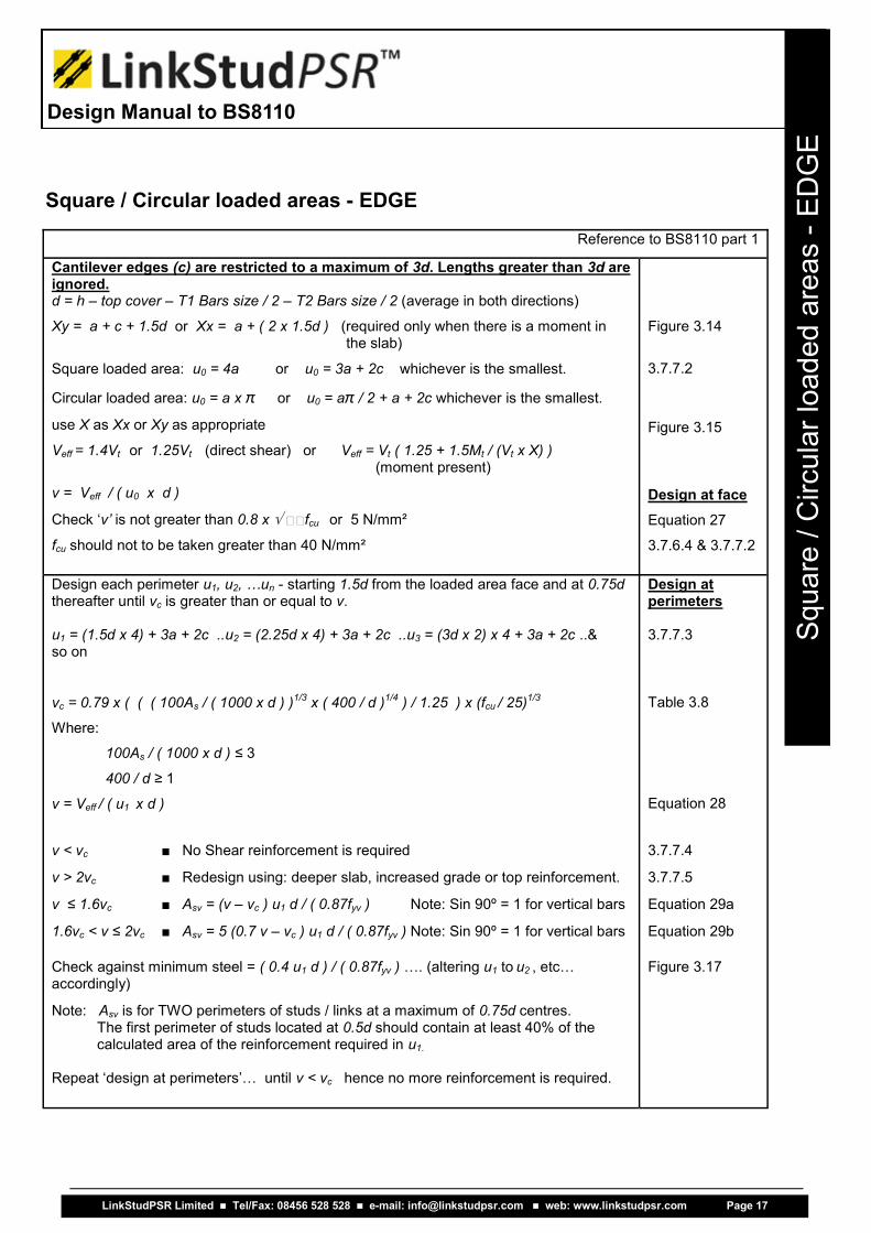
Reference to BS8110 part 1
Cantilever edges (c) are restricted to a maximum of 3d. Lengths greater than 3d are ignored. d = h – top cover – T1 Bars size / 2 – T2 Bars size / 2 (average in both directions)
Xy = a + c + 1.5d or Xx = a + ( 2 x 1.5d ) (required only when there is a moment in the slab)
Square loaded area: u0 = 4a or u0 = 3a + 2c whichever is the smallest.
Circular loaded area: u0 = a x π or u0 = aπ / 2 + a + 2c whichever is the smallest.
use X as Xx or Xy as appropriate
Veff = 1.4Vt or 1.25Vt (direct shear) or Veff = Vt ( 1.25 + 1.5Mt / (Vt x X) ) (moment present)
v = Veff / ( u0 x d )
Check ‘v’ is not greater than 0.8 x fcu or 5 N/mm²
fcu should not to be taken greater than 40 N/mm²
Figure 3.14
3.7.7.2
Figure 3.15 Design at face
Equation 27
3.7.6.4 & 3.7.7.2
Design each perimeter u1, u2, …un - starting 1.5d from the loaded area face and at 0.75d thereafter until vc is greater than or equal to v. u1 = (1.5d x 4) + 3a + 2c ..u2 = (2.25d x 4) + 3a + 2c ..u3 = (3d x 2) x 4 + 3a + 2c ..& so on
vc = 0.79 x ( ( ( 100As / ( 1000 x d ) )1/3
x ( 400 / d )1/4
) / 1.25 ) x (fcu / 25)1/3
Where:
100As / ( 1000 x d ) ≤ 3 400 / d ≥ 1
v = Veff / ( u1 x d )
Design at perimeters 3.7.7.3
Table 3.8
Equation 28
v < vc
v > 2vc
v ≤ 1.6vc
1.6vc < v ≤ 2vc
■ No Shear reinforcement is required
■ Redesign using: deeper slab, increased grade or top reinforcement.
■ Asv = (v – vc ) u1 d / ( 0.87fyv ) Note: Sin 90º = 1 for vertical bars
■ Asv = 5 (0.7 v – vc ) u1 d / ( 0.87fyv ) Note: Sin 90º = 1 for vertical bars
3.7.7.4
3.7.7.5
Equation 29a
Equation 29b
Check against minimum steel = ( 0.4 u1 d ) / ( 0.87fyv ) …. (altering u1 to u2 , etc…accordingly)
Note: Asv is for TWO perimeters of studs / links at a maximum of 0.75d centres. The first perimeter of studs located at 0.5d should contain at least 40% of the calculated area of the reinforcement required in u1.
Repeat ‘design at perimeters’… until v < vc hence no more reinforcement is required.
Figure 3.17
Square / Circular loaded areas - EDGE
LinkStudPSR Limited Tel/Fax: 08456 528 528 e-mail: [email protected] web: www.linkstudpsr.com Page 17
Design Manual to BS8110
Sq
ua
re / C
ircu
lar
load
ed
are
as -
ED
GE

Square loaded area - External corner Square loaded area - External corner
Circular loaded area - External corner Circular loaded area - External corner
LinkStudPSR Limited Tel/Fax: 08456 528 528 e-mail: [email protected] web: www.linkstudpsr.com Page 18
Design Manual to BS8110
Sq
ua
re / C
ircu
lar
load
ed
are
as -
EX
TE
RN
AL C
OR
NE
R

Reference to BS8110 part 1 Cantilever edges (c,d) are restricted to a maximum of 3d. Lengths greater than 3d are ignored. d = h – top cover – T1 Bars size / 2 – T2 Bars size / 2 (average in both directions)
Xy = a + c + 1.5d or Xx = a + e + 1.5d (required only when there is a moment in the slab)
Square loaded area: u0 = 4a or u0 = 2a + c + e or u0 = 3a + 2c or u0 = 3a + 2e whichever is the smallest.
Circular loaded area: u0 = a x π or u0 = aπ / 4 + a + c + e whichever is the smallest.
use X as Xx or Xy as appropriate
Veff = 1.25Vt (direct shear) or Veff = Vt ( 1.25 + 1.5Mt / (Vt x X) ) (moment present)
v = Veff / ( u0 x d )
Check ‘v’ is not greater than 0.8 x fcu or 5 N/mm²
fcu should not to be taken greater than 40 N/mm²
Figure 3.14
3.7.7.2
Figure 3.15 Design at face
Equation 27
3.7.6.4 & 3.7.7.2
Design each perimeter u1, u2, …un - starting 1.5d from the loaded area face and at 0.75d thereafter until vc is greater than or equal to v. u1 = (1.5d x 2) + 2a + c + e ..u2 = (2.25d x 2) + 2a + c + e ..u3 = (3d x 2) + 2a + c + e ... & so on
vc = 0.79 x ( ( ( 100As / ( 1000 x d ) )1/3
x ( 400 / d )1/4
) / 1.25 ) x (fcu / 25)1/3
Where:
100As / ( 1000 x d ) ≤ 3 400 / d ≥ 1
v = Veff / ( u1 x d )
Design at perimeters 3.7.7.3
Table 3.8
Equation 28
v < vc
v > 2vc
v ≤ 1.6vc
1.6vc < v ≤ 2vc
■ No Shear reinforcement is required
■ Redesign using: deeper slab, increased grade or top reinforcement.
■ Asv = (v – vc ) u1 d / ( 0.87fyv ) Note: Sin 90º = 1 for vertical bars
■ Asv = 5 (0.7 v – vc ) u1 d / ( 0.87fyv ) Note: Sin 90º = 1 for vertical bars
3.7.7.4
3.7.7.5
Equation 29a
Equation 29b
Check against minimum steel = ( 0.4 u1 d ) / ( 0.87fyv ) …. (altering u1 to u2 , etc…accordingly)
Note: Asv is for TWO perimeters of studs / links at a maximum of 0.75d centres. The first perimeter of studs located at 0.5d should contain at least 40% of the calculated area of the reinforcement required in u1.
Repeat ‘design at perimeters’… until v < vc hence no more reinforcement is required.
Figure 3.17
Square / Circular loaded areas - EXTERNAL CORNER
LinkStudPSR Limited Tel/Fax: 08456 528 528 e-mail: [email protected] web: www.linkstudpsr.com Page 19
Design Manual to BS8110
Sq
ua
re / C
ircu
lar
load
ed
are
as -
EX
TE
RN
AL C
OR
NE
R
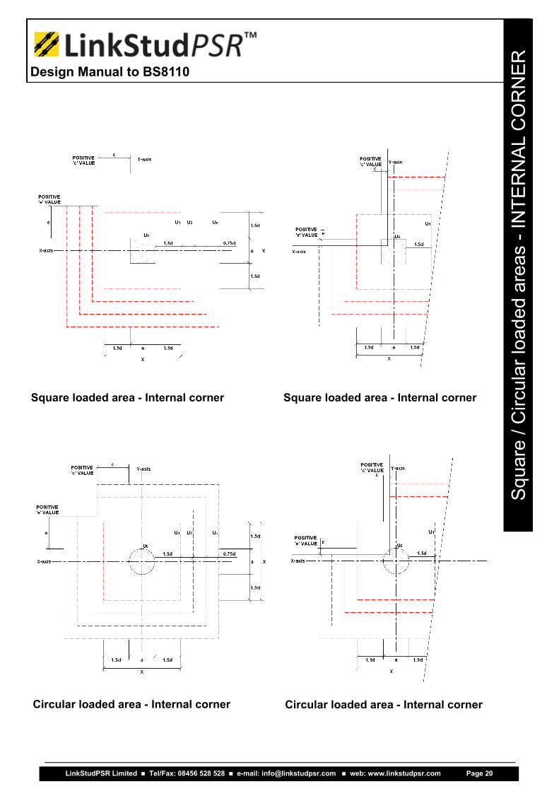
Square loaded area - Internal corner Square loaded area - Internal corner
Circular loaded area - Internal corner Circular loaded area - Internal corner
LinkStudPSR Limited Tel/Fax: 08456 528 528 e-mail: [email protected] web: www.linkstudpsr.com Page 20
Design Manual to BS8110
Sq
ua
re / C
ircu
lar
load
ed
are
as -
INT
ER
NA
L C
OR
NE
R

Reference to BS8110 part 1
Cantilever edges (c,e) are restricted to a maximum of 1.5d. Lengths greater than 1.5d are ignored. d = h – top cover – T1 Bars size / 2 – T2 Bars size / 2 (average in both directions)
Xy = a + 3d or Xx = a + 3d (required only when there is a moment in the slab)
Square loaded area: u0 = 4a or u0 = 4a + c + e whichever is the smallest.
Circular loaded area: u0 = aπ or u0 = aπ3/4 + a + c + e whichever is the smallest.
use X as Xx or Xy as appropriate
Veff = 1.25Vt (direct shear) or Veff = Vt ( 1.25 + 1.5Mt / (Vt x X) ) (moment present)
v = Veff / ( u0 x d )
Check ‘v’ is not greater than 0.8 x fcu or 5 N/mm²
fcu should not to be taken greater than 40 N/mm²
Figure 3.14
3.7.7.2
Figure 3.15 Design at face
Equation 27
3.7.6.4 & 3.7.7.2
Design each perimeter u1, u2, …un - starting 1.5d from the loaded area face and at 0.75d thereafter until vc is greater than or equal to v. u1 = (1.5d x 6) + 4a + c + e ..u2 = (2.25d x 6) + 4a + c + e ..u3 = (3d x 6) + 4a + c + e ... & so on
Check u1, u2, etc.. Against a complete enclosed perimeter i.e. u1 = ( ( 1.5d x 2) + a ) x 4
vc = 0.79 x ( ( ( 100As / ( 1000 x d ) )1/3
x ( 400 / d )1/4
) / 1.25 ) x (fcu / 25)1/3
Where:
100As / ( 1000 x d ) ≤ 3 400 / d ≥ 1
v = Veff / ( u1 x d )
Design at perimeters 3.7.7.3
Table 3.8
Equation 28
v < vc
v > 2vc
v ≤ 1.6vc
1.6vc < v ≤ 2vc
■ No Shear reinforcement is required
■ Redesign using: deeper slab, increased grade or top reinforcement.
■ Asv = (v – vc ) u1 d / ( 0.87fyv ) Note: Sin 90º = 1 for vertical bars
■ Asv = 5 (0.7 v – vc ) u1 d / ( 0.87fyv ) Note: Sin 90º = 1 for vertical bars
3.7.7.4
3.7.7.5
Equation 29a
Equation 29b
Check against minimum steel = ( 0.4 u1 d ) / ( 0.87fyv ) …. (altering u1 to u2 , etc…accordingly)
Note: Asv is for TWO perimeters of studs / links at a maximum of 0.75d centres. The first perimeter of studs located at 0.5d should contain at least 40% of the calculated area of the reinforcement required in u1.
Repeat ‘design at perimeters’… until v < vc hence no more reinforcement is required.
Figure 3.17
Square / Circular loaded areas - INTERNAL CORNER
LinkStudPSR Limited Tel/Fax: 08456 528 528 e-mail: [email protected] web: www.linkstudpsr.com Page 21
Design Manual to BS8110
Sq
ua
re / C
ircu
lar
load
ed
are
as -
INT
ER
NA
L C
OR
NE
R
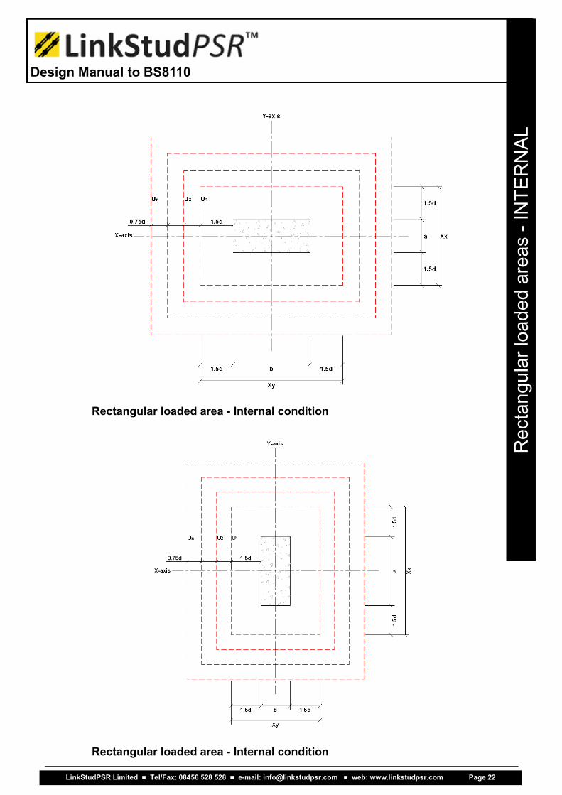
Rectangular loaded area - Internal condition
Rectangular loaded area - Internal condition
LinkStudPSR Limited Tel/Fax: 08456 528 528 e-mail: [email protected] web: www.linkstudpsr.com Page 22
Design Manual to BS8110
Re
cta
ng
ula
r lo
ad
ed
are
as -
INT
ER
NA
L
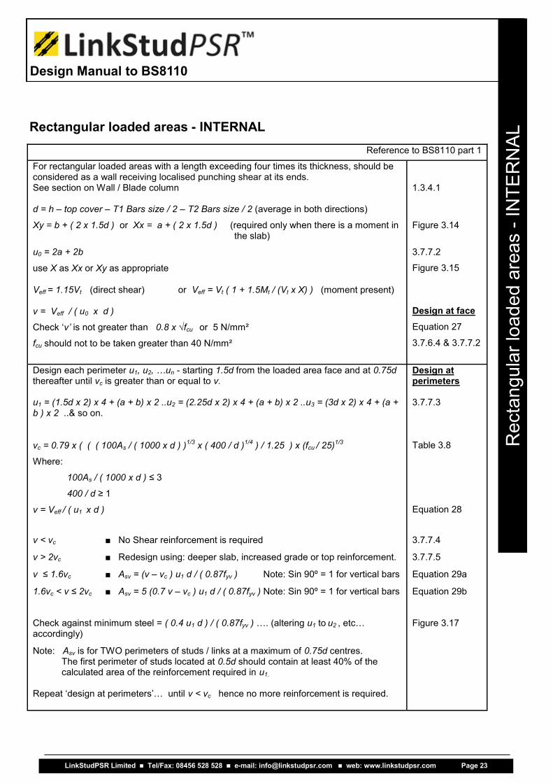
Rectangular loaded areas - INTERNAL Reference to BS8110 part 1
For rectangular loaded areas with a length exceeding four times its thickness, should be considered as a wall receiving localised punching shear at its ends. See section on Wall / Blade column d = h – top cover – T1 Bars size / 2 – T2 Bars size / 2 (average in both directions)
Xy = b + ( 2 x 1.5d ) or Xx = a + ( 2 x 1.5d ) (required only when there is a moment in the slab)
u0 = 2a + 2b
use X as Xx or Xy as appropriate
Veff = 1.15Vt (direct shear) or Veff = Vt ( 1 + 1.5Mt / (Vt x X) ) (moment present) v = Veff / ( u0 x d )
Check ‘v’ is not greater than 0.8 x √fcu or 5 N/mm²
fcu should not to be taken greater than 40 N/mm²
1.3.4.1
Figure 3.14
3.7.7.2
Figure 3.15 Design at face
Equation 27
3.7.6.4 & 3.7.7.2
Design each perimeter u1, u2, …un - starting 1.5d from the loaded area face and at 0.75d thereafter until vc is greater than or equal to v. u1 = (1.5d x 2) x 4 + (a + b) x 2 ..u2 = (2.25d x 2) x 4 + (a + b) x 2 ..u3 = (3d x 2) x 4 + (a + b ) x 2 ..& so on.
vc = 0.79 x ( ( ( 100As / ( 1000 x d ) )1/3
x ( 400 / d )1/4
) / 1.25 ) x (fcu / 25)1/3
Where:
100As / ( 1000 x d ) ≤ 3 400 / d ≥ 1
v = Veff / ( u1 x d )
Design at perimeters 3.7.7.3
Table 3.8
Equation 28
v < vc
v > 2vc
v ≤ 1.6vc
1.6vc < v ≤ 2vc
■ No Shear reinforcement is required
■ Redesign using: deeper slab, increased grade or top reinforcement.
■ Asv = (v – vc ) u1 d / ( 0.87fyv ) Note: Sin 90º = 1 for vertical bars
■ Asv = 5 (0.7 v – vc ) u1 d / ( 0.87fyv ) Note: Sin 90º = 1 for vertical bars
3.7.7.4
3.7.7.5
Equation 29a
Equation 29b
Check against minimum steel = ( 0.4 u1 d ) / ( 0.87fyv ) …. (altering u1 to u2 , etc…accordingly)
Note: Asv is for TWO perimeters of studs / links at a maximum of 0.75d centres.The first perimeter of studs located at 0.5d should contain at least 40% of the calculated area of the reinforcement required in u1.
Repeat ‘design at perimeters’… until v < vc hence no more reinforcement is required.
Figure 3.17
LinkStudPSR Limited Tel/Fax: 08456 528 528 e-mail: [email protected] web: www.linkstudpsr.com Page 23
Design Manual to BS8110
Re
cta
ng
ula
r lo
ad
ed
are
as -
INT
ER
NA
L

Rectangular loaded area - Edge condition
Rectangular loaded area - Edge condition
LinkStudPSR Limited Tel/Fax: 08456 528 528 e-mail: [email protected] web: www.linkstudpsr.com Page 24
Design Manual to BS8110
Re
cta
ng
ula
r lo
ad
ed
are
as -
ED
GE
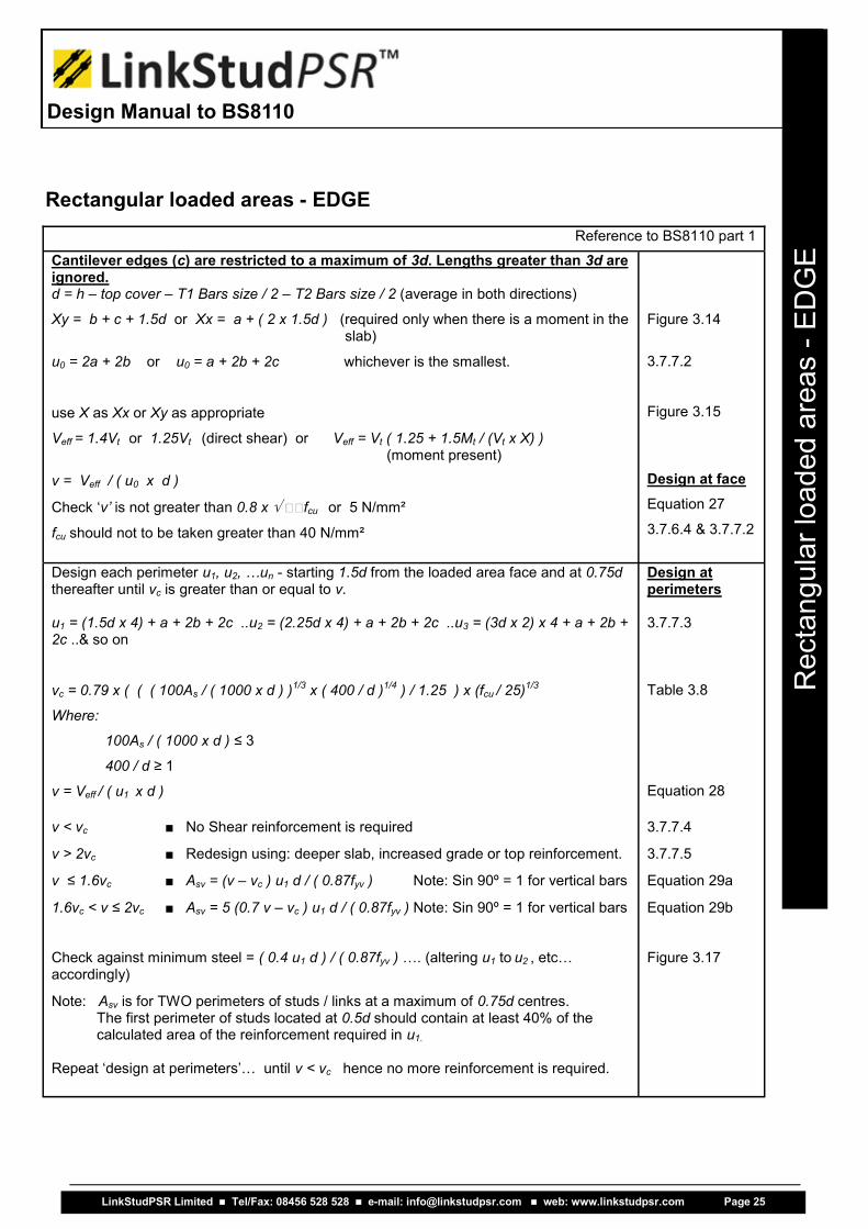
Reference to BS8110 part 1
Cantilever edges (c) are restricted to a maximum of 3d. Lengths greater than 3d are ignored. d = h – top cover – T1 Bars size / 2 – T2 Bars size / 2 (average in both directions)
Xy = b + c + 1.5d or Xx = a + ( 2 x 1.5d ) (required only when there is a moment in the slab)
u0 = 2a + 2b or u0 = a + 2b + 2c whichever is the smallest.
use X as Xx or Xy as appropriate
Veff = 1.4Vt or 1.25Vt (direct shear) or Veff = Vt ( 1.25 + 1.5Mt / (Vt x X) ) (moment present)
v = Veff / ( u0 x d )
Check ‘v’ is not greater than 0.8 x fcu or 5 N/mm²
fcu should not to be taken greater than 40 N/mm²
Figure 3.14
3.7.7.2
Figure 3.15 Design at face
Equation 27
3.7.6.4 & 3.7.7.2
Design each perimeter u1, u2, …un - starting 1.5d from the loaded area face and at 0.75d thereafter until vc is greater than or equal to v. u1 = (1.5d x 4) + a + 2b + 2c ..u2 = (2.25d x 4) + a + 2b + 2c ..u3 = (3d x 2) x 4 + a + 2b + 2c ..& so on
vc = 0.79 x ( ( ( 100As / ( 1000 x d ) )1/3
x ( 400 / d )1/4
) / 1.25 ) x (fcu / 25)1/3
Where:
100As / ( 1000 x d ) ≤ 3 400 / d ≥ 1
v = Veff / ( u1 x d )
Design at perimeters 3.7.7.3
Table 3.8
Equation 28 v < vc
v > 2vc
v ≤ 1.6vc
1.6vc < v ≤ 2vc
■ No Shear reinforcement is required
■ Redesign using: deeper slab, increased grade or top reinforcement.
■ Asv = (v – vc ) u1 d / ( 0.87fyv ) Note: Sin 90º = 1 for vertical bars
■ Asv = 5 (0.7 v – vc ) u1 d / ( 0.87fyv ) Note: Sin 90º = 1 for vertical bars
3.7.7.4
3.7.7.5
Equation 29a
Equation 29b
Check against minimum steel = ( 0.4 u1 d ) / ( 0.87fyv ) …. (altering u1 to u2 , etc…accordingly)
Note: Asv is for TWO perimeters of studs / links at a maximum of 0.75d centres. The first perimeter of studs located at 0.5d should contain at least 40% of the calculated area of the reinforcement required in u1.
Repeat ‘design at perimeters’… until v < vc hence no more reinforcement is required.
Figure 3.17
Rectangular loaded areas - EDGE
LinkStudPSR Limited Tel/Fax: 08456 528 528 e-mail: [email protected] web: www.linkstudpsr.com Page 25
Design Manual to BS8110
Re
cta
ng
ula
r lo
ad
ed
are
as -
ED
GE
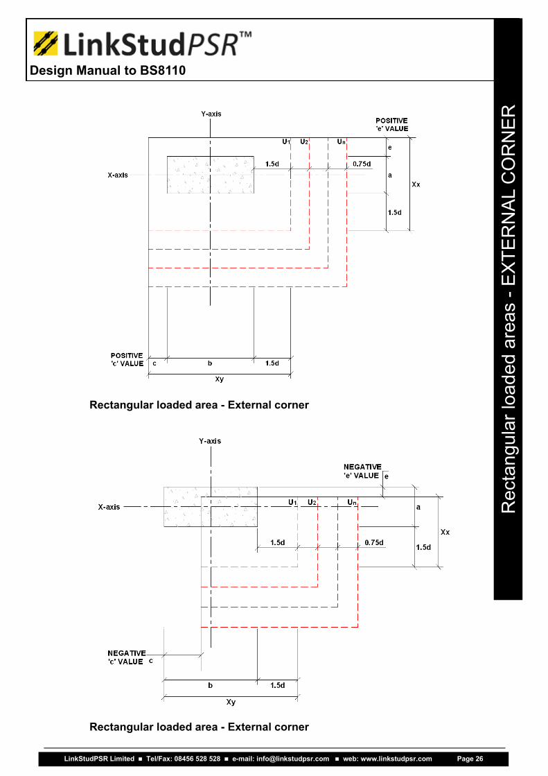
Rectangular loaded area - External corner
Rectangular loaded area - External corner
LinkStudPSR Limited Tel/Fax: 08456 528 528 e-mail: [email protected] web: www.linkstudpsr.com Page 26
Design Manual to BS8110
Re
cta
ng
ula
r lo
ad
ed
are
as -
EX
TE
RN
AL C
OR
NE
R

Reference to BS8110 part 1
Cantilever edges (c) are restricted to a maximum of 3d. Lengths greater than 3d are ignored. d = h – top cover – T1 Bars size / 2 – T2 Bars size / 2 (average in both directions)
Xy = b + c + 1.5d or Xx = a + e + 1.5d (required only when there is a moment in the slab)
u0 = 2a + 2b or u0 = a + b + c + e or u0 = a + 2b + 2c or u0 = 2a + b + 2e whichever is the smallest.
use X as Xx or Xy as appropriate
Veff = 1.25Vt (direct shear) or Veff = Vt ( 1.25 + 1.5Mt / (Vt x X) ) (moment present)
v = Veff / ( u0 x d )
Check ‘v’ is not greater than 0.8 x fcu or 5 N/mm²
fcu should not to be taken greater than 40 N/mm²
Figure 3.14
3.7.7.2
Figure 3.15 Design at face
Equation 27
3.7.6.4 & 3.7.7.2
Design each perimeter u1, u2, …un - starting 1.5d from the loaded area face and at 0.75d thereafter until vc is greater than or equal to v. u1 = (1.5d x 2) + a + b + c + e ..u2 = (2.25d x 2) + a + b + c + e ..u3 = (3d x 2) + a + b + c + e ... & so on.
vc = 0.79 x ( ( ( 100As / ( 1000 x d ) )1/3
x ( 400 / d )1/4
) / 1.25 ) x (fcu / 25)1/3
Where:
100As / ( 1000 x d ) ≤ 3 400 / d ≥ 1
v = Veff / ( u1 x d )
Design at perimeters 3.7.7.3
Table 3.8
Equation 28
v < vc
v > 2vc
v ≤ 1.6vc
1.6vc < v ≤ 2vc
■ No Shear reinforcement is required
■ Redesign using: deeper slab, increased grade or top reinforcement.
■ Asv = (v – vc ) u1 d / ( 0.87fyv ) Note: Sin 90º = 1 for vertical bars
■ Asv = 5 (0.7 v – vc ) u1 d / ( 0.87fyv ) Note: Sin 90º = 1 for vertical bars
3.7.7.4
3.7.7.5
Equation 29a
Equation 29b
Check against minimum steel = ( 0.4 u1 d ) / ( 0.87fyv ) …. (altering u1 to u2 , etc…accordingly)
Note: Asv is for TWO perimeters of studs / links at a maximum of 0.75d centres. The first perimeter of studs located at 0.5d should contain at least 40% of the calculated area of the reinforcement required in u1.
Repeat ‘design at perimeters’… until v < vc hence no more reinforcement is required.
Figure 3.17
Rectangular loaded areas - EXTERNAL CORNER
LinkStudPSR Limited Tel/Fax: 08456 528 528 e-mail: [email protected] web: www.linkstudpsr.com Page 27
Design Manual to BS8110
Re
cta
ng
ula
r lo
ad
ed
are
as -
EX
TE
RN
AL C
OR
NE
R

Rectangular loaded area - Internal corner
Rectangular loaded area - Internal corner
LinkStudPSR Limited Tel/Fax: 08456 528 528 e-mail: [email protected] web: www.linkstudpsr.com Page 28
Design Manual to BS8110
Re
cta
ng
ula
r lo
ad
ed
are
as -
INT
ER
NA
L C
OR
NE
R

Reference to BS8110 part 1
Cantilever edges (c,e) are restricted to a maximum of 1.5d. Lengths greater than 1.5d are ignored. d = h – top cover – T1 Bars size / 2 – T2 Bars size / 2 (average in both directions)
Xy = b + 3d or Xx = a + 3d (required only when there is a moment in the slab)
u0 = 2a + 2b or u0 = a + b + c + e whichever is the smallest.
use X as Xx or Xy as appropriate
Veff = 1.25Vt (direct shear) or Veff = Vt ( 1.25 + 1.5Mt / (Vt x X) ) (moment present)
v = Veff / ( u0 x d )
Check ‘v’ is not greater than 0.8 x fcu or 5 N/mm²
fcu should not to be taken greater than 40 N/mm²
Figure 3.14
3.7.7.2
Figure 3.15 Design at face
Equation 27
3.7.6.4 & 3.7.7.2
Design each perimeter u1, u2, …un - starting 1.5d from the loaded area face and at 0.75d thereafter until vc is greater than or equal to v. u1 = (1.5d x 6) + 2a + 2b + c + e ..u2 = (2.25d x 6) + 2a + 2b + c + e ..u3 = (3d x 6) + 2a + 2b + c + e ... & so on
Check u1, u2, etc.. Against a complete enclosed perimeter i.e. u1 = ( ( 1.5d x 2 ) x 4 + 2a + 2b)
vc = 0.79 x ( ( ( 100As / ( 1000 x d ) )1/3
x ( 400 / d )1/4
) / 1.25 ) x (fcu / 25)1/3
Where:
100As / ( 1000 x d ) ≤ 3 400 / d ≥ 1
v = Veff / ( u1 x d )
Design at perimeters 3.7.7.3
Table 3.8
Equation 28
v < vc
v > 2vc
v ≤ 1.6vc
1.6vc < v ≤ 2vc
■ No Shear reinforcement is required
■ Redesign using: deeper slab, increased grade or top reinforcement.
■ Asv = (v – vc ) u1 d / ( 0.87fyv ) Note: Sin 90º = 1 for vertical bars
■ Asv = 5 (0.7 v – vc ) u1 d / ( 0.87fyv ) Note: Sin 90º = 1 for vertical bars
3.7.7.4
3.7.7.5
Equation 29a
Equation 29b
Check against minimum steel = ( 0.4 u1 d ) / ( 0.87fyv ) …. (altering u1 to u2 , etc…accordingly)
Note: Asv is for TWO perimeters of studs / links at a maximum of 0.75d centres. The first perimeter of studs located at 0.5d should contain at least 40% of the calculated area of the reinforcement required in u1.
Repeat ‘design at perimeters’… until v < vc hence no more reinforcement is required.
Figure 3.17
Rectangular loaded areas - INTERNAL CORNER
LinkStudPSR Limited Tel/Fax: 08456 528 528 e-mail: [email protected] web: www.linkstudpsr.com Page 29
Design Manual to BS8110
Re
cta
ng
ula
r lo
ad
ed
are
as -
INT
ER
NA
L C
OR
NE
R

Design guidance for large columns or walls
BS8110 part 1 1997 1.3.4.1
A vertical load bearing member whose length exceeds four times its thickness. Loaded areas with a length greater than four times its thickness are considered to be a wall and as such localised punching will occur at the ends or corners. This subject is not covered by BS8110 part 1 1997. Therefore, to conform to the code, it could be assumed that the perimeters could be returned around the ends by two times the thickness (2 x ‘a’). i.e. a loaded area 800 x 200 in size would be treated as a normal punching shear situation, whereas a 1000 x 200 loaded area would retain the same perimeter size as the 800 x 200 example (the shear force may be reduced due to direct shear taken across the middle part of the loaded area / wall). The Project Engineer should be consulted first as to if and how this can be achieved. This topic is however also covered by the Eurocode in more depth for edge and corner conditions adopting the smaller dimension of < 1.5d or < 0.5c1, where c1 can be taken as half the loaded area / wall length. The final decision should rest with the Project Engineer who is fully aware of the whole structure. It would therefore be easier to separate each end of the loaded area / wall and calculate it as an edge condition with the respective loaded area width ‘a’ and the return dimension ‘R’ being considered as the small-er of 2a, 1.5d or 0.5c1. Still retaining the factor of Veff = 1.25Vt for the edge condition and half the loading unless otherwise specified. Large loaded area corners or wall corners can be addressed in a similar manner, returning each side by 1.5d and calculated as a corner condition (as indicated below).
LinkStudPSR Limited Tel/Fax: 08456 528 528 e-mail: [email protected] web: www.linkstudpsr.com Page 30
Design Manual to BS8110
BS
811
0 D
esig
n g
uid
an
ce
fo
r la
rge
co
lum
ns o
r w
alls

Design guidance for holes / penetrations through slabs
BS8110 part 1 1997 3.7.7.6 Modification of effective perimeter to allow for holes.
When a hole or holes are within 6d from the face of the loaded area, part of the perimeter that is enclosed by the radial projections (dead zone) from the centre of the loaded area to the edges of the hole(s) are considered ineffective.
Each perimeter (u0, u1, etc..) must be reduced accordingly and any studs / reinforcement ignored when calculating the area of steel required / used. Care should be taken when repositioning rails to miss holes that it has not moved into another perimeter without adjusting the calculation likewise.
A single hole can be ignored if its largest width is less than the smaller of:
1. One quarter of the side of the loaded area
2. Half the slab depth
It may be desirable or quicker to consider a worst case design, ignoring the part of the slab with the hole(s) and design as an edge or corner condition, supplying additional rails to the disregarded area of slab that will be receiving load from the slab.
Alternatively, a percentage reduction of the perimeters can be used, but care must be taken, as the percentage will vary due to the position around the loaded area and with the distance between the loaded area and the hole.
LinkStudPSR Limited Tel/Fax: 08456 528 528 e-mail: [email protected] web: www.linkstudpsr.com Page 31
Design Manual to BS8110
BS
811
0 D
esig
n g
uid
an
ce
fo
r h
ole
s t
hro
ug
h s
lab
s
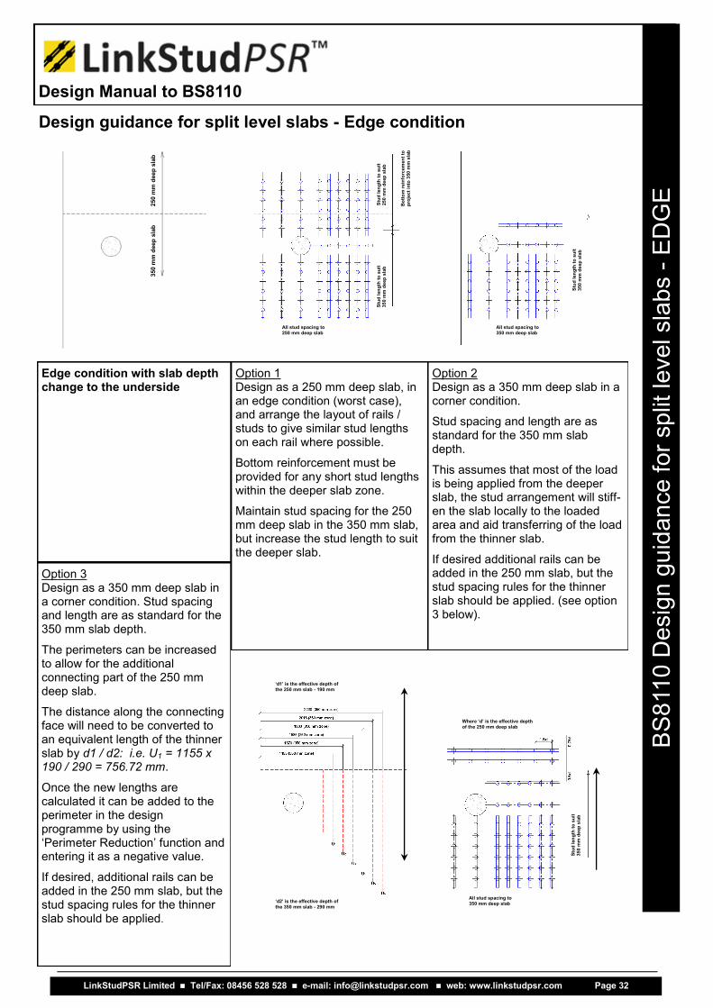
Option 1 Design as a 250 mm deep slab, in an edge condition (worst case), and arrange the layout of rails / studs to give similar stud lengths on each rail where possible.
Bottom reinforcement must be provided for any short stud lengths within the deeper slab zone.
Maintain stud spacing for the 250 mm deep slab in the 350 mm slab, but increase the stud length to suit the deeper slab.
Edge condition with slab depth change to the underside
Option 2 Design as a 350 mm deep slab in a corner condition.
Stud spacing and length are as standard for the 350 mm slab depth.
This assumes that most of the load is being applied from the deeper slab, the stud arrangement will stiff-en the slab locally to the loaded area and aid transferring of the load from the thinner slab.
If desired additional rails can be added in the 250 mm slab, but the stud spacing rules for the thinner slab should be applied. (see option 3 below).
Option 3 Design as a 350 mm deep slab in a corner condition. Stud spacing and length are as standard for the 350 mm slab depth.
The perimeters can be increased to allow for the additional connecting part of the 250 mm deep slab.
The distance along the connecting face will need to be converted to an equivalent length of the thinner slab by d1 / d2: i.e. U1 = 1155 x 190 / 290 = 756.72 mm.
Once the new lengths are calculated it can be added to the perimeter in the design programme by using the ‘Perimeter Reduction’ function and entering it as a negative value.
If desired, additional rails can be added in the 250 mm slab, but the stud spacing rules for the thinner slab should be applied.
Design guidance for split level slabs - Edge condition
LinkStudPSR Limited Tel/Fax: 08456 528 528 e-mail: [email protected] web: www.linkstudpsr.com Page 32
Design Manual to BS8110
BS
811
0 D
esig
n g
uid
an
ce
fo
r sp
lit le
ve
l sla
bs -
ED
GE
350 m
m d
eep
sla
b
250 m
m d
eep
sla
b
Stu
d l
en
gth
to
su
it
35
0 m
m d
eep
sla
b
Stu
d l
en
gth
to
su
it
25
0 m
m d
eep
sla
b
Bo
tto
m r
ein
forc
em
en
t to
p
roje
ct
into
350
mm
sla
b
All stud spacing to 250 mm deep slab
All stud spacing to 350 mm deep slab
Stu
d l
en
gth
to
su
it
35
0 m
m d
eep
sla
b
‘d1’ is the effective depth of the 250 mm slab - 190 mm
‘d2’ is the effective depth of
the 350 mm slab - 290 mm
All stud spacing to 350 mm deep slab
Stu
d l
en
gth
to
su
it
35
0 m
m d
eep
sla
b
Where ‘d’ is the effective depth of the 250 mm deep slab

Design guidance for split level slabs - Internal condition
Internal condition with slab depth change within the loaded area zone. Option 1
Design as an ‘Internal Condition’ using the smaller slab depth (worst case), arrange the layout of rails / studs to give similar stud lengths on each rail where possible.
Bottom reinforcement must be provided for any short stud lengths within the deeper slab zone.
Maintain stud spacing for the 250 mm slab within the 350 mm slab, but increase the stud length to suit the deeper slab. Option 2
Design as an ‘Edge Condition’ using the deeper slab depth.
The perimeters can be increased to allow for the additional connecting part of the 250 mm deep slab.
The distance along the connecting face will need to be converted to an equivalent length of the thinner slab by d1 / d2.
Once the new lengths are calculated it can be added to the perimeter in the design programme by using the ‘Perimeter Reduction’ function and entering it as a negative value.
If desired additional rails can be added in the 250 mm slab, but the stud spacing rules for the thinner slab should be applied Option 3
Determine the loads on each side of the loaded area and design as two separate edge conditions:
■ 350 mm deep edge slab ■ 250 mm deep edge slab
Stud spacing and length will vary either side of the loaded area.
Note: the Veff factor should be calculated as an ‘Edge Condition’ on each side.
A A
LinkStudPSR Limited Tel/Fax: 08456 528 528 e-mail: [email protected] web: www.linkstudpsr.com Page 33
Design Manual to BS8110
BS
811
0 D
esig
n g
uid
an
ce
fo
r sp
lit le
ve
l sla
bs -
INT
ER
NA
L
350 mm deep slab 250 mm deep slab
Section A-A
Stud length extended to suit 350 mm slab
All stud spacing to suit 250 mm slab
Stud length to suit 350 mm deep slab
Co
nvert
to
an
eq
uiv
ale
nt
350 m
m d
eep
sla
b
Stud length to suit 350 mm deep slab
Stud length to suit 250 mm deep slab

Design guidance for split level slabs - Internal condition
Internal condition with slab depth change outside the loaded area zone. Option 1
Design as an ‘Internal Condition’ using the smaller slab depth (worst case), arrange the layout of rails / studs to give similar stud lengths on each rail where possible.
Bottom reinforcement must be provided for any short stud lengths within the deeper slab zone.
Maintain stud spacing for the 250 mm slab within the 350 mm slab, but increase the stud length to suit the deeper slab. Option 2
Design as a ‘Cantilever Edge Condition’ using the deeper slab depth.
Stud length and spacing to suit the 350 mm deep slab. Option 3
Design as a ‘Cantilever Edge Condition’ using the deeper slab depth.
The perimeters can be increased to allow for the additional connecting part of the 250 mm deep slab.
The distance along the connecting face will need to be converted to an equivalent length of the thinner slab by d1 / d2.
Once the new lengths are calculated it can be added to the perimeter in the design programme by using the ‘Perimeter Reduction’ function and entering it as a negative value.
A A
LinkStudPSR Limited Tel/Fax: 08456 528 528 e-mail: [email protected] web: www.linkstudpsr.com Page 34
Design Manual to BS8110
BS
811
0 D
esig
n g
uid
an
ce
fo
r sp
lit le
ve
l sla
bs -
INT
ER
NA
L 350 mm deep slab 250 mm deep slab
Section A-A
Stud length extended to suit 350 mm slab
All stud spacing to suit 250 mm slab
Stud length to suit 350 mm deep slab
Stud length to suit 350 mm deep slab
Co
nvert
to
an
eq
uiv
ale
nt
350 m
m d
eep
sla
b

NOTES:
LinkStudPSR Limited Tel/Fax: 08456 528 528 e-mail: [email protected] web: www.linkstudpsr.com Page 35
Design Manual to BS8110
NO
TE
S
Related Documents


