DOE/WIPP-99-2308 REV. 6 Delaware Basin Monitoring Annual Report September 2005 United States Department of Energy Waste Isolation Pilot Plant Carlsbad Field Office Carlsbad, New Mexico

Welcome message from author
This document is posted to help you gain knowledge. Please leave a comment to let me know what you think about it! Share it to your friends and learn new things together.
Transcript
DOE/WIPP-99-2308REV. 6
Delaware Basin Monitoring Annual Report
September 2005
United States Department of EnergyWaste Isolation Pilot Plant
Carlsbad Field OfficeCarlsbad, New Mexico
DOE/WIPP-99-2308, REV. 6 i September 30, 2005
Delaware Basin Monitoring Annual Report
September 2005
United States Department of EnergyWaste Isolation Pilot Plant
Carlsbad Field OfficeCarlsbad, New Mexico
Prepared forthe Department of Energy by
Washington Regulatory & Environmental ServicesDavid Hughes
Delaware Basin Drilling Surveillance Program
DOE/WIPP-99-2308, REV. 6 ii September 30, 2005
Table of Contents
1.0 Delaware Basin Drilling Surveillance Program 1
2.0 2005 Updates 2
2.1 Miscellaneous Drilling Information 22.1.1 Drilling Techniques 32.1.2 Drilling Fluids 42.1.3 Air Drilling 4
2.2 Shallow Drilling Events 62.3 Deep Drilling Events 62.4 Past Drilling Rates 72.5 Current Drilling Rate 7
2.5.1 Nine-Township Area Drilling Activities 82.5.2 Drilling Activities Outside the Nine-Township Area 8
2.6 Castile Brine Encounters 82.7 Borehole Permeability Assessment - Plugging Practices 92.8 Seismic Activity in the Delaware Basin 112.9 Secondary and Tertiary Recovery 11
2.9.1 Nine-Township Area Injection Wells 122.9.2 Nine-Township Area Salt Water Disposal Wells 12
2.10 Pipeline Activity 122.11 Mining 13
2.11.1 Potash Mining 132.11.2 Sulfur Extraction 142.11.3 Solution Mining 14
2.12 New Drilling Technology 15
3.0 Survey of Well Operators for Drilling Information 15
4.0 Summary - 2005 Delaware Basin Drilling Surveillance Program 16
5.0 References 17
DOE/WIPP-99-2308, REV. 6 iii September 30, 2005
List of Figures
Figure 1 WIPP Site, Delaware Basin, and Surrounding Area 18Figure 2 Typical Well Structure and General Stratigraphy Near the WIPP Site 19Figure 3 Oil and Gas Wells Within One Mile of the WIPP Site 20Figure 4 Typical Borehole Plug Configurations in the Delaware Basin 21Figure 5 Typical Injection or Salt Water Disposal Well (SWD) 22Figure 6 Active Injection and SWD Wells in the Nine-Township Area 23Figure 7 Potash Mining in the Vicinity of the WIPP Site 24Figure 8 Active Brine Well Locations in the Delaware Basin 25
List of Tables
Table 1 Nine-Township Area Casing Sizes 26Table 2 Nine-Township Area Bit Sizes 26Table 3 Air-Drilled Wells in the New Mexico Portion of the Delaware Basin 27Table 4 Shallow Well Status in the Delaware Basin 28Table 5 Deep Well Status in the Delaware Basin 29Table 6 Past Drilling Rates for the Delaware Basin 30Table 7 Castile Brine Encounters in the Vicinity of the WIPP Site 31Table 8 Plugged Well Information 33Table 9 Plugging Summary by Well Type 36Table 10 Seismic Activity in the Delaware Basin 37Table 11 Nine-Township Injection and SWD Well Information 38Table 12 Brine Well Status in the Delaware Basin 40

DOE/WIPP-99-2308, REV. 6 1 September 30, 2005
1.0 Delaware Basin Drilling Surveillance Program
The Delaware Basin Drilling Surveillance Program (DBDSP) is designed to monitor drillingactivities in the vicinity of the Waste Isolation Pilot Plant (WIPP). This program is based onEnvironmental Protection Agency (EPA) criteria. The EPA environmental radiation protectionstandards for the management and disposal of spent nuclear fuel, high-level and transuranicradioactive wastes are codified in Title 40 Code of Federal Regulations (CFR) Part 191 (EPA1993). Subpart B of the standard addresses the disposal of radioactive waste. The standardrequires the Department of Energy (DOE) to demonstrate the expected performance of thedisposal system using a probabilistic risk assessment or performance assessment (PA). Theresults of the PA must show that the expected repository performance will not result in therelease of radioactive material above limits set by the EPA’s standard. This assessment mustinclude the consideration of inadvertent drilling into the repository at some future time.
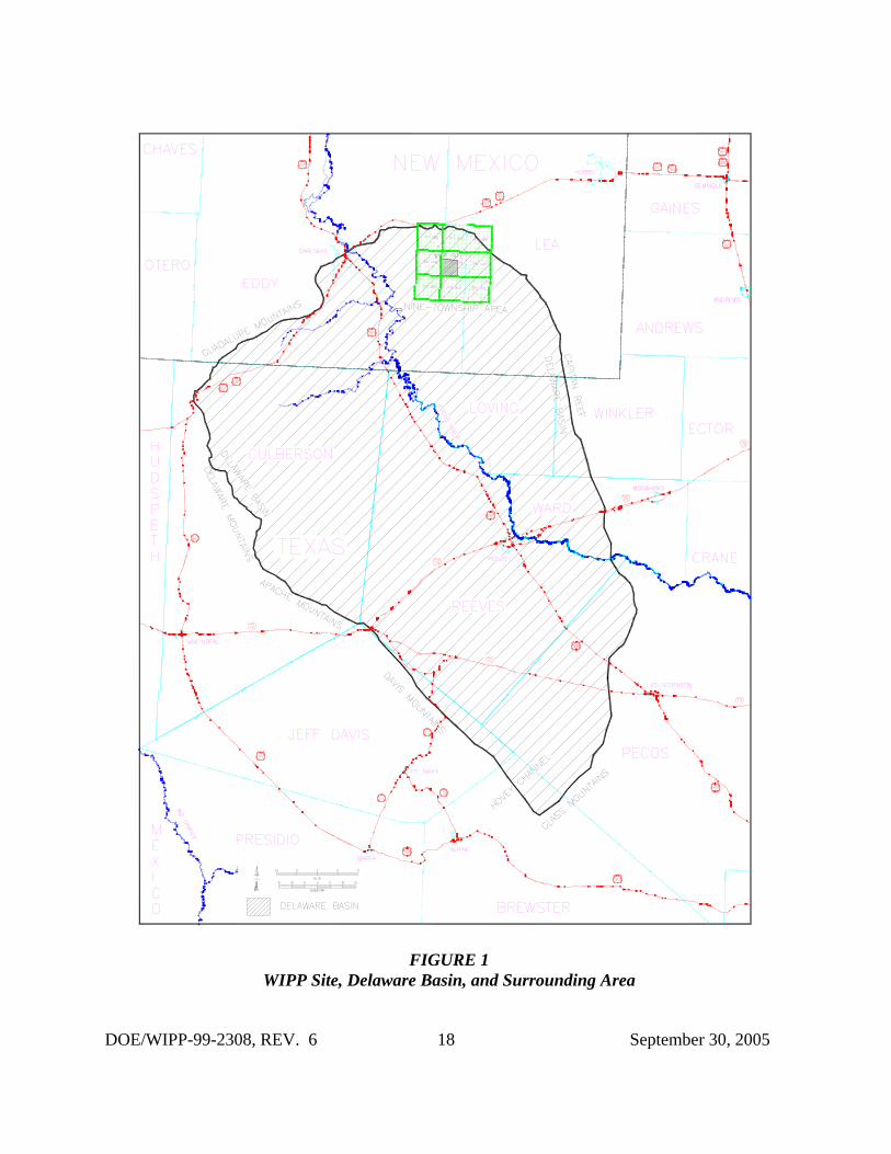
In 40 CFR Part 194 (EPA 1996), the EPA defined the geographical area for the evaluation of thehistorical rate of drilling for resources, as the Delaware Basin. This same area is to be used formonitoring drilling and drilling-related activities. The definition of the Delaware Basin in 40CFR § 194.2 is:
“Delaware Basin means those surface and subsurface features which lie inside the boundaryformed to the north, east and west of the [WIPP] disposal system, by the innermost edge of theCapitan Reef, and formed, to the south, by a straight line drawn from the southeastern point ofthe Davis Mountains to the most southwestern point of the Glass Mountains.”
The Delaware Basin, depicted in Figure 1, includes all or part of Brewster, Culberson, JeffDavis, Loving, Pecos, Reeves, Ward, and Winkler counties in west Texas, and portions of Eddyand Lea counties in southeastern New Mexico.
The DOE continues to provide surveillance of the drilling activity in the Delaware Basin inaccordance with the criteria established in 40 CFR Part 194. This will continue until the DOEand the EPA mutually agree no further benefit can be gained from continued surveillance. Theresults of the ongoing surveillance will be used to determine if a significant and detrimentalchange has occurred that would affect the performance of the disposal system.
The Delaware Basin Drilling Surveillance Plan (WP 02-PC.02) places specific emphasis on thenine-township area that includes the WIPP Site and provides data to build on the informationpresented in Appendix DEL of the Compliance Certification Application (CCA) (DOE 1996)and Appendix DATA of the Compliance Recertification Application (CRA) (DOE 2004).
DOE/WIPP-99-2308, REV. 6 2 September 30, 2005
2.0 2005 Updates
The PA is required by regulation to consider disturbed case scenarios that include intrusions intothe repository by inadvertent and intermittent drilling for resources. The probability of theseintrusions is based on a future drilling rate of 46.8 boreholes per square kilometer per 10,000years which was established for the 1996 CCA in Appendix DEL and 52.5 boreholes per squarekilometer for the 2004 CRA in Appendix DATA. These rates are based on consideration of therecord of drilling events in the Delaware Basin for the most recent 100-year period. The DOEmodels multiple types of human intrusion scenarios in the PA. These include both singleintrusion events and combinations of multiple boreholes.
Two different types of boreholes are considered: (1) those that penetrate a pressurized brinereservoir in the underlying Castile Formation and (2) those that do not. While the presence ofpressurized brine under the repository is speculative, it cannot be completely ruled out based onavailable information. The primary consequence of contacting pressurized brine is theintroduction of an additional source of brine beyond that which is assumed to be released into therepository from the Salado Formation. The human intrusion scenario models are based onextensive field data sets collected by the DOE. The DBDSP collects the drilling-related data tobe used for future PA calculations. The data have been continuously collected from the time ofthe 1996 submittal of the CCA and include specific wells drilled during the last year in the NewMexico portion of the Delaware Basin, specifically that of the nine-township area immediatelysurrounding the WIPP Site. These data are summarized in the following sections.
2.1 Miscellaneous Drilling Information
The EPA provided criteria in 40 CFR §194.33(c) to address the consideration of drilling in thePA. These criteria led to the formulation of conceptual models that incorporate the effects ofthese activities. The conceptual models use parameter values as documented in Appendix DELof the CCA, such as:
• drill collar diameter and length• casing diameters• drill pipe diameter• speed of drill string rotation through the Salado Formation• penetration rate through the Salado Formation• instances of air drilling• types of drilling fluids• amounts of drilling fluids• borehole depths• borehole diameters• borehole plugs• fraction of each borehole that is plugged• instances of encountering pressurized brine in the Castile Formation
DOE/WIPP-99-2308, REV. 6 3 September 30, 2005
The DBDSP data set includes the final borehole depth for all wells drilled in the Delaware Basin. Borehole depths range from 19 feet to 25,201 feet. The 19-foot hole is an exhaust shaftmonitoring well located on the WIPP Site, and the 25,201-foot hole is a gas well located inTexas. Borehole depths in the immediate vicinity of the WIPP Site typically range from 7,750feet to 9,000 feet for oil wells and 13,000 feet to 16,000 feet for gas wells.
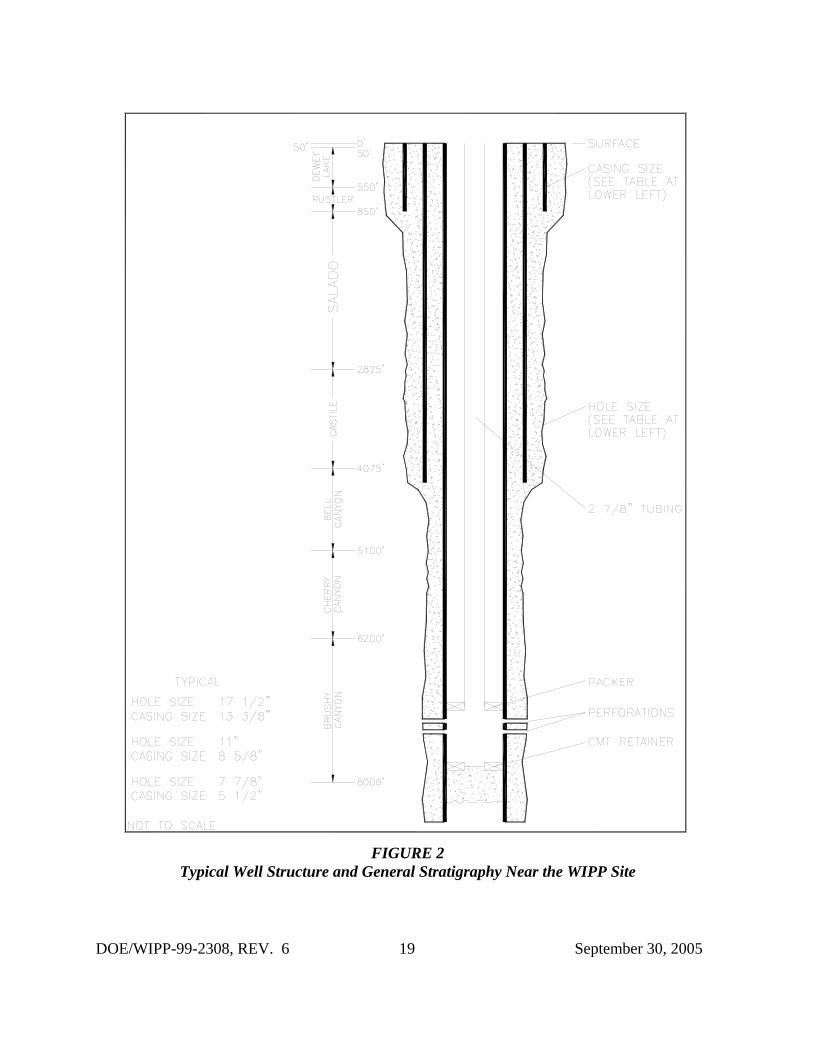
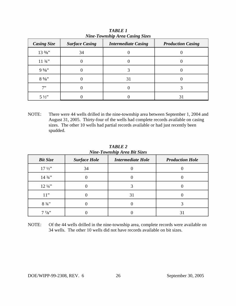
The diameter of each well bore is more difficult to ascertain. The DBDSP data set included thecasing size and depth for each section of the hole (Table 1). Drill bit size is not a reportableelement, although hole sizes are reported on Sundry notices (miscellaneous forms) maintained bythe New Mexico Oil Conservation Division (NMOCD). The casing size or hole size is used todetermine the size of the bit used to drill that particular section of the well. Currently, the mostcommon bit sizes are 17 ½ in. for the surface section, 11 in. for the intermediate section, and 7 fin. for the production section of the hole. Table 2 shows the documented bit sizes used indrilling wells in the nine-township area during the past year.
In the early days of well drilling, the 12 ¼ in. bit was popular with rotary drill operators for thesurface section of the hole. In those days, the wells were much shallower and did not require thelarger casing sizes. Most holes drilled at that time were two-string (string refers to the differentsize of casing in the wellbore) holes versus the three- and four-strings commonly used now. Inthe area of the WIPP Site, regulations in the area designated by the Secretary of Interior as theKnown Potash Leasing Area (KPLA) require a three-string hole making the larger bit sizes morepopular. The typical hole and casing sizes for a three-string well in the vicinity of the WIPP Siteare shown in Figure 2.
When drilling a well, many factors come into play: the depth to be drilled, the geology of thesubstrata, the equipment being used, etc. In the early 1950s, it commonly took an average of 50days to drill a well to depth. Today it takes approximately 20 days to drill a well to depth.
2.1.1 Drilling Techniques
The drilling techniques reported in Appendix DEL of the CCA are still being implemented byarea drillers. There were a total of 204 hydrocarbon wells spudded, not necessarily completed,in the New Mexico portion of the Delaware Basin from September 1, 2004 through August 31,2005. This number is derived from the databases maintained by the DBDSP. In reality, thenumber of new wells is higher; but the paperwork on some of the wells has not yet been filedwith the NMOCD or will be filed after the writing of this report. Therefore, those wells are notincluded in the count listed above.
Rotary drilling rigs were used to drill all 204 wells. Some have been completed as oil wells,others as gas wells, while the rest are still in the process of being completed. Five wells weredry holes or junked and abandoned. All were conventionally drilled utilizing mud as a mediumfor circulation. Forty-four of these wells were in the nine-township area. The depths of thecompleted wells in the nine-township area range from 7,347 feet to 11,950 feet. Outside of thenine-township area the depths of the completed wells range from 3,200 feet to 16,600 feet.
DOE/WIPP-99-2308, REV. 6 4 September 30, 2005
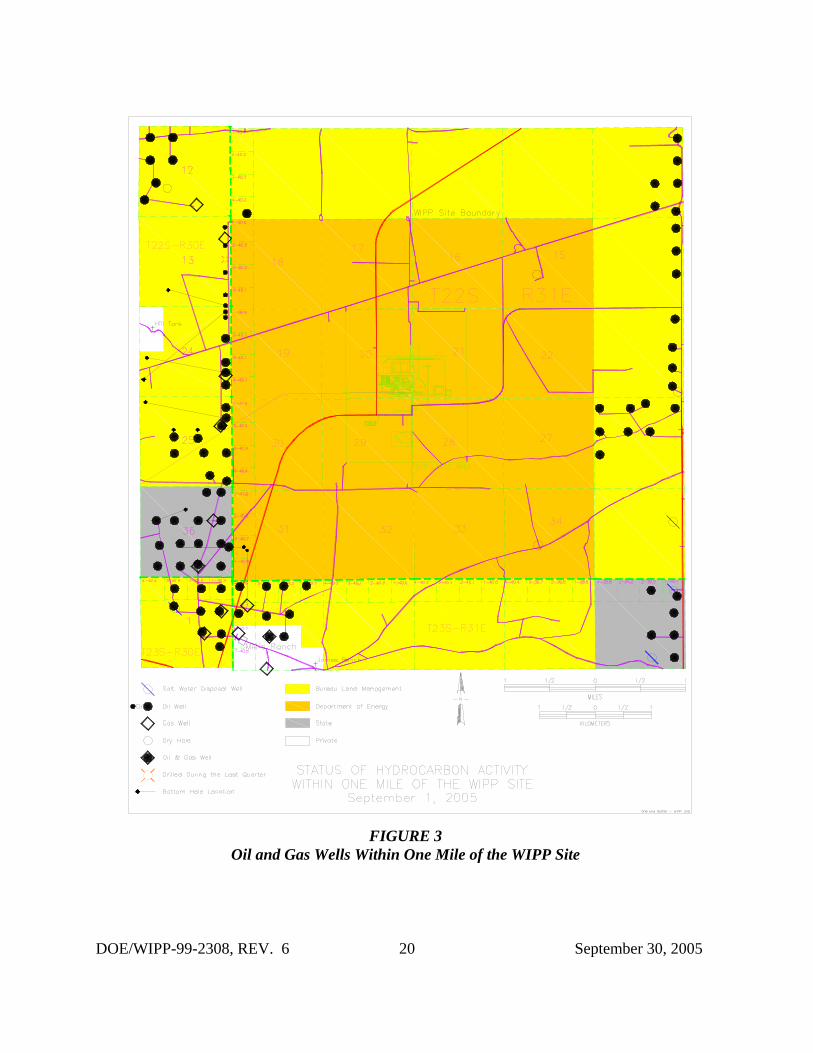
A technique used by operators to increase production is to drill a well horizontally after a targetdepth is reached, which allows for more of the wellbore area to be in the production zone. Asreported in Appendix DEL, this technique is not often used in this area because of the increasedcosts (it adds to the drilling time). The DBDSP monitors directional and horizontally drilledwells only in the nine-township area. Four of the 44 new wells spudded during the last year inthe nine-township area had horizontally drilled components. All four are located in T22S-R30E-Sections 13, 24, and 25 (See Figure 3).
2.1.2 Drilling Fluids
Employing a rotary rig for drilling involves the use of drilling fluids. Drilling fluid is commonlyknown as mud, which is the liquid circulated through the wellbore during rotary drilling andworkover operations. In addition to its function of bringing cuttings to the surface, drilling mudcools and lubricates the bit and drill stem, protects against blowouts by holding back subsurfacepressures, and deposits a mud cake on the wall of the borehole to prevent loss of fluids to theformation.
Typically, a driller will use fresh water and additives to drill the surface section of the holewhich ends at the top of the Salado Formation. A change in drilling practices would necessitatea change in the application of drilling fluids. Within the KPLA of southeastern New Mexico,drillers are required under Title 19, Chapter 15, Order R-111-P of the New MexicoAdministrative Code (NMAC) to use a saturated brine to drill through the salt formation whichis usually called the intermediate section. This requirement is to keep the salt from washing outand making the hole larger than necessary. Once this section has been drilled and cased, thedriller again changes to fresh water and additives to finish drilling the hole to depth.
2.1.3 Air Drilling
A method of hydrocarbon drilling not emphasized in CCA Appendix DEL is air drilling. Asdefined by the oil industry, air drilling is a method of rotary drilling using compressed air as thecirculation medium. The conventional method of removing cuttings from the wellbore is to usea flow of water or drilling mud. In some cases, compressed air removes the cuttings with equalor greater efficiency. The rate of penetration is usually increased considerably when air drillingis used; however, a fundamental problem in air drilling is the penetration of formationscontaining water, since the entry of water into the system reduces the ability of the air to removecuttings.
Critics noted the air drilling scenario was not included by the DOE in the CCA and raisedseveral issues: (1) air drilling technology is currently successfully used in the Delaware Basin,(2) air drilling is thought to be a viable drilling technology under the hydrological and geologicalconditions at the WIPP Site, and (3) air drilling could result in releases of radionuclides that aresubstantially greater than those considered by the DOE in the CCA. Considerable research onair drilling in the Delaware Basin has determined that although air drilling is a common methodof drilling wells, it is not practiced in the vicinity of the WIPP Site because (1) it is against R-
DOE/WIPP-99-2308, REV. 6 5 September 30, 2005
111-P regulations to drill with anything but saturated brine through the salt formation in theKPLA; (2) it is not economical to drill with air when a driller has to use saturated brine for theintermediate section; and (3) if water is encountered prior to or after drilling the salt formation,the driller would have to convert to a conventional system of drilling.
Additional information was provided to EPA Air Docket No. A-93-02, IV-G-7. In thisinformation, the following was provided:
The well record search has continued and now includes information from the entire New Mexicoportion of the Delaware Basin. Within the nine-townships surrounding the WIPP, the recordsshowed no evidence of air drilling. One possible exception to this may be the Lincoln Federal #1. This well is said to have been air drilled due to a loss of circulation at a depth of 1290 feet, but thishas not been verified. The records associated with the Lincoln Federal #1 do not contain anyevidence of air drilling. Rather, this information is based on verbal communications with theoperating and drilling companies involved with the well. Nonetheless, the Lincoln Federal #1 mayhave been drilled with air, although it was not a systematic use of the technology. Air drilling atthis well was used from 2984' to 4725' merely as a mitigative attempt to continue drilling to thenext casing transition depth. After this casing transition, mud drilling was used for the remainderof the hole.
The area of the expanded search contains 3,756 boreholes. Of these, 407 well files wereunavailable for viewing (in process), therefore, 3,349 well files constitute the database. Amongthese wells, 11 instances of air drilling were found in which any portion of the borehole wasdrilled with air. Only 7 of these were drilled through the Salado Formation at the depth of therepository. This results in a frequency of 7/3349, or 0.0021. This value is conservative in that itincludes the Lincoln Federal #1, and four other wells which were proposed to be drilled with air,but no subsequent verification of actual drilling exists in the records.
In the Final Rule, the EPA ruled air drilling did not have to be considered for PA; however, theDBDSP will continue to monitor for instances of air drilling.
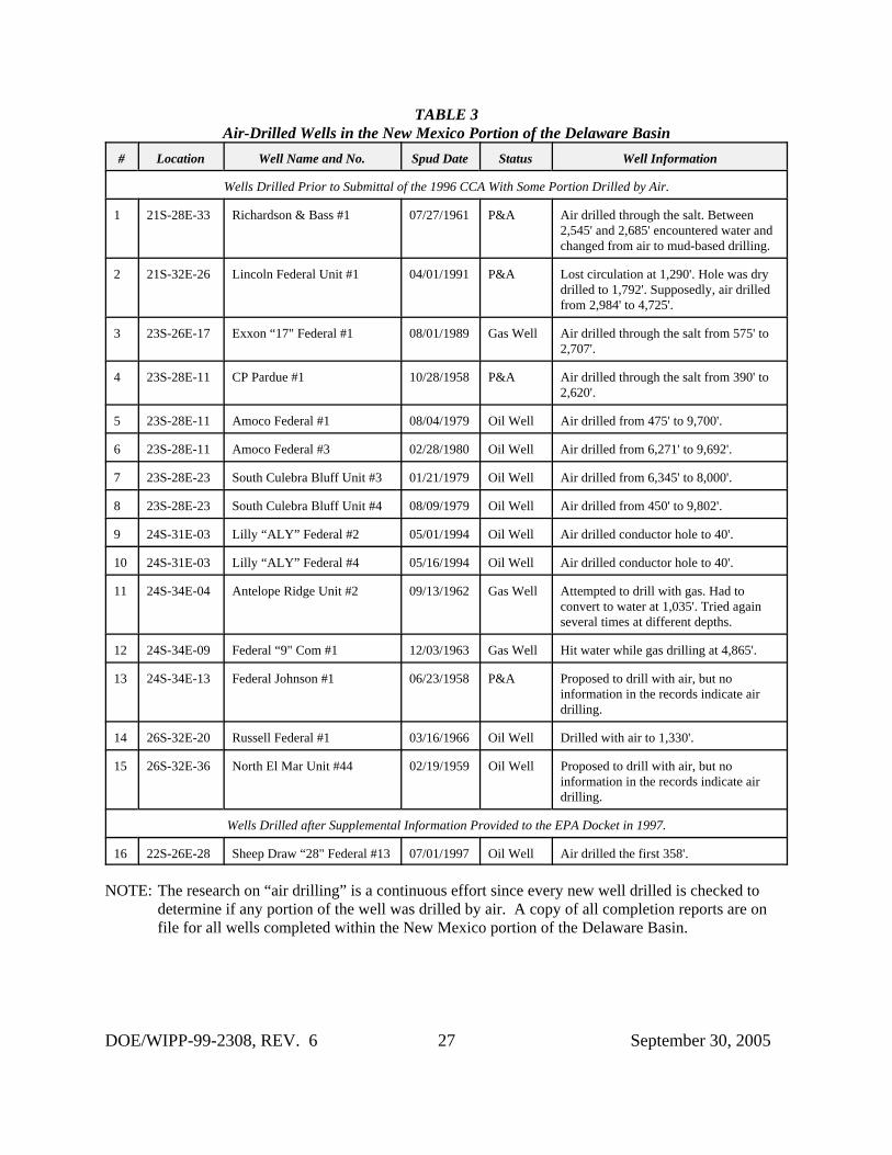
During the summer of 1999, another search of these same records was conducted as a follow upto the original research. This search of the records was used as a quality assurance check of theoriginal search. The database consisted of 3,810 boreholes with only 12 records unavailable forviewing. This search added five more wells with indications of some portion of the hole beingdrilled with air. None were located in the nine-township area or were air drilled through theSalado Formation. Of the five wells added to the count, one (the Sheep Draw “28" Federal #13)had the first 358 feet air drilled while the other four had the conductor pipe drilled with air whichconsists of the first 40 feet of the borehole and is not usually reported in the drilling process. The conductor casing is typically drilled, set in place, and cemented prior to setting up the rotarydrilling rig that will eventually drill the well.
The records on the new wells spudded during the last year (September 1, 2004 through August31, 2005) are being checked as they become available at the NMOCD Internet site for instancesof air drilling. The records can be submitted to the NMOCD offices as late as two years after thewell has been drilled. The record review is an ongoing process conducted on a continuing basis. None of the records reviewed to date have indicated any additional instances of air drilling. As
DOE/WIPP-99-2308, REV. 6 6 September 30, 2005
was presented in the testimony (public hearings conducted by the EPA on WIPP certification)and continues to be validated by ongoing review, air drilling is not a common practice in thevicinity of the WIPP Site. Table 3 shows all of the known indications of air drilling that haveoccurred in the New Mexico portion of the Delaware Basin.
2.2 Shallow Drilling Events
One of the criteria of 40 CFR Part 194 is that the CCA must adequately and accuratelycharacterize the frequency of shallow drilling within the Delaware Basin, as well as, support theassumptions and determinations, particularly those that limit consideration of shallow drillingevents based on the presence of resources of similar type and quantity found in the controlledarea. The DOE concluded in Appendix SCR that shallow drilling could be removed from PAconsideration based on low consequence. As a result, the DOE did not include shallow drillingin its PA drilling rate calculations and did not include any reduction in shallow drilling ratesduring the active and passive institutional control periods. In Compliance Application ReviewDocument (CARD) 32, the EPA accepted the DOE’s finding that shallow drilling would be oflow consequence to repository performance and need not be included in the PA.
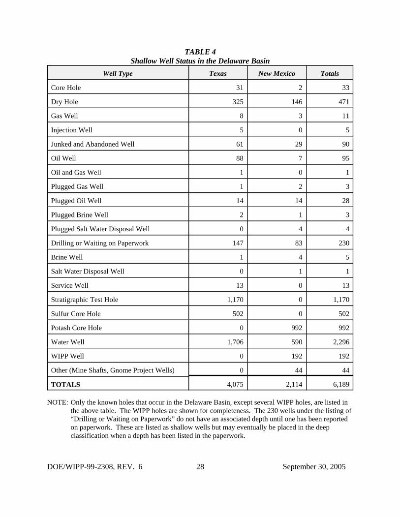
Although the EPA has agreed shallow drilling can be eliminated from the PA and need not betracked, the DBDSP collects data on all wells reported to be drilled within the boundaries of theDelaware Basin. The program makes no distinctions between shallow and deep drilling eventsexcept when calculating the intrusion rate for deep drilling. Information on all wells drilled isvital for trending future activities. Table 4 shows a breakdown of the various types and numberof shallow wells located within the Delaware Basin.
2.3 Deep Drilling Events
In accordance with the criteria, the DOE used the historical rate of drilling for resources in theDelaware Basin to calculate a future drilling rate. In particular, in calculating the frequency offuture deep drilling, 40 CFR §194.33(b)(3)(i) (EPA 1996) provided the following criteria to theDOE:
Identify deep drilling that has occurred for each resource in the Delaware Basin over the past 100years prior to the time at which a compliance application is prepared.
The DOE used the historical record of deep drilling for resources below 2,150 feet that hasoccurred over the past 100 years in the Delaware Basin. This was chosen because it is the depthof the repository, and the repository is not directly breached by boreholes less than this depth. Inthe past 100 years, deep drilling occurred for oil, gas, potash, and sulfur. These drilling eventswere used in calculating a rate for deep drilling for the PA as discussed in Appendix DEL of theCCA. The period of calculation used was from 1896 through June 1995. Historical drilling forpurposes other than resource exploration and recovery (such as WIPP Site investigation) wereexcluded from the calculation in accordance with criteria provided in 40 CFR §194.33.
DOE/WIPP-99-2308, REV. 6 7 September 30, 2005
In the Delaware Basin, deep drilling events are usually associated with oil and gas drilling.Commercial sources and visits to the NMOCD offices and Internet site are used to identify theseevents. The DBDSP collects data on all drilled wells within the Delaware Basin, making nodistinction between resources. Two separate databases are maintained on hydrocarbon wells,one for Texas and one for New Mexico. As information on wells is acquired, it is entered intothe individual databases. The Texas database contains information only on the current status ofthe well, when it was drilled, its location, who the operator is, and the total depth of the well. The Texas portion of the Delaware Basin is used only for calculating the drilling rate. Thedatabase for the New Mexico portion of the Delaware Basin contains the same basic informationas Texas along with all the information required for PA related drilling events.
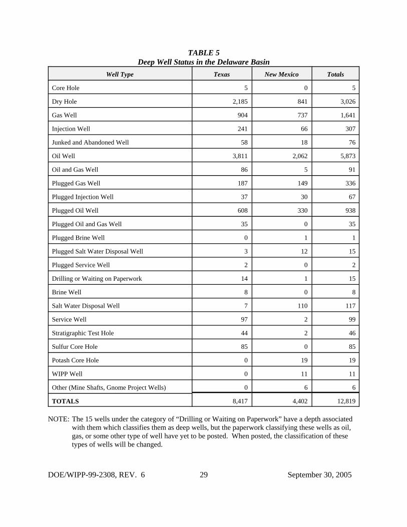
The DBDSP continues to monitor all hydrocarbon drilling activity and any new potash, sulfur,water, or monitoring wells for deep-drilling events. Information from the drilling of these wellsis added to the databases maintained for these separate resources. During the last year, therewere 367 new wells added to the databases. Most of the wells were drilled for hydrocarbonextraction and almost all were deep-drilling events. Forty-four of these new wells are in thenine-township area immediately surrounding the WIPP Site. Table 5 shows the number and typeof deep wells located in the Delaware Basin.
2.4 Past Drilling Rates
The EPA provided a formula for calculating the current drilling rate or intrusion rate when 40CFR Part 194 was promulgated. The formula is as follows: number of holes drilled in the last100 years times 10,000 years divided by the area of the Delaware Basin (23,102.1 km2) dividedby 100 years (1897-1996, the year the CCA was submitted). Since shallow drilling events are oflow consequence, only deep drilling events are applied to the formula. The DBDSP uses alldeep drilling events of any resource (potash, oil, gas, water, etc.) to calculate the drilling orintrusion rate.
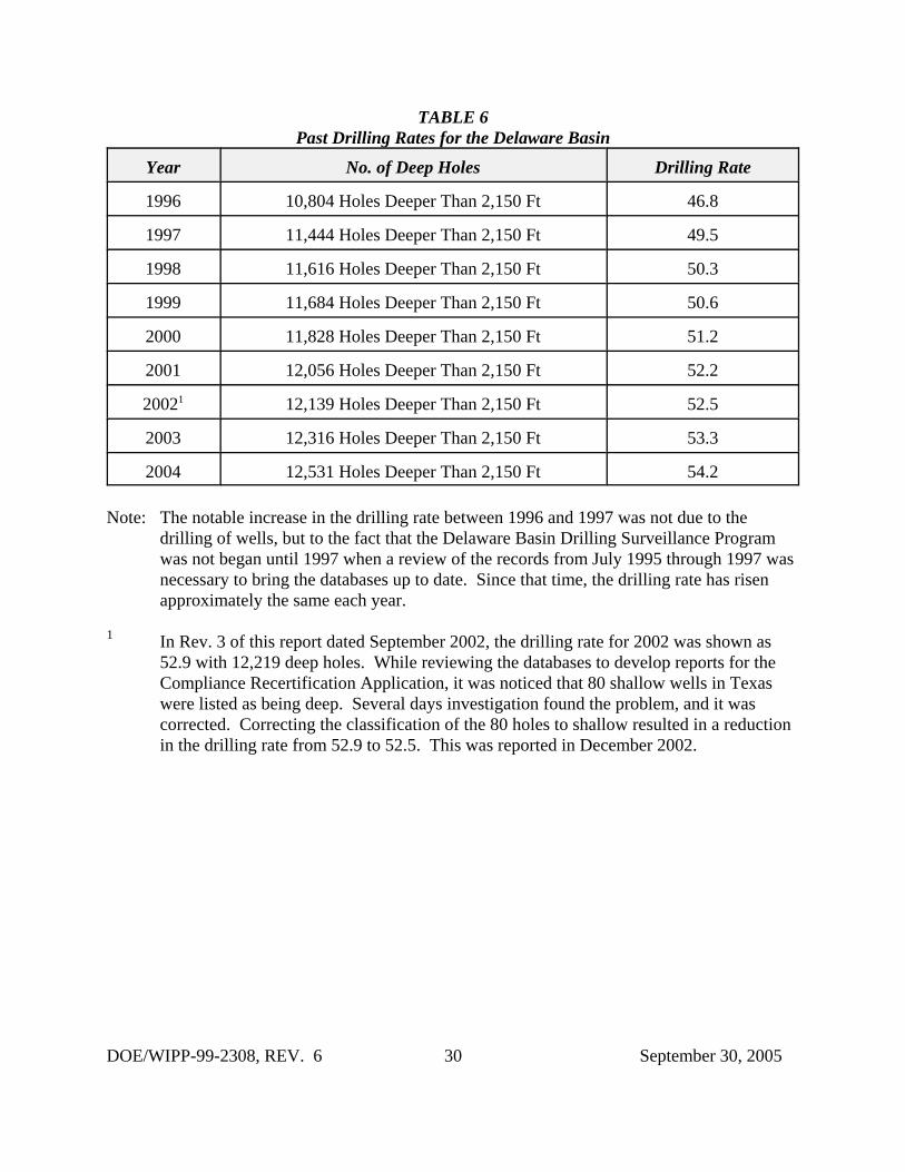
The drilling rates since the submittal of the CCA in 1996 are shown in Table 6. The largeincrease between 1996 and 1997 is the result of updating the databases with information fromJune 1995 through August 1997. Also, the 100-year window is considered a sliding window, inwhich 100 years worth of data are used each time the calculation is performed. As each newyear’s data are added, the oldest year’s data are dropped. For example, the drilling rate wascalculated in 1999 by using the data from 1900 through 1999. In 2000, the data from 1901through 2000 was used to calculate the drilling rate.
2.5 Current Drilling Rate
The calculated intrusion or drilling rate for 2005 was derived from the information provided in Table 5. There were 12,819 boreholes deeper than 2,150 feet. Applying the formula results inthe following: 12,819 boreholes x 10,000 years / 23,102.1 km2 / 100 years. This results in adrilling or intrusion rate of 55.5 boreholes per km2 over 10,000 years.
DOE/WIPP-99-2308, REV. 6 8 September 30, 2005
This is an increase from the 46.8 boreholes per km2 reported in the 1996 CCA. This number isanticipated to rise for several more years before it begins to drop. This is because of the 100-year time frame used for drilling results. As new wells are added to the count, wells older than100 years are dropped. It will be 2011 before any wells are dropped from the count while anumber of new wells will be added due to ongoing oil and gas drilling activity, thus increasingthe rate.
2.5.1 Nine-Township Area Drilling Activities
From September 1, 2004 to August 31, 2005, there were 44 new wells spudded in the nine-township area immediately surrounding the WIPP Site. Six new wells were drilled in the one-mile area surrounding the WIPP Site with all immediately to the west of the site. Figure 3 showsthe status of all known hydrocarbon wells drilled within the one-mile area of the WIPP Site. Ofthe 44 new wells, 34 were drilled in Eddy County and ten in Lea County. Eleven of the wellswere to the northeast and east of the site, six to the west of the site, while the rest were all southof the site. Devon Energy Production Company drilled the most new wells in the nine-townshiparea with 20 wells. Pogo Producing Company had five new wells, and Yates PetroleumCorporation drilled eight new wells in the nine-township area during the last year. These threecompanies are the major producers in the area along with other companies such as, StrataProduction Company, Bass Enterprises Production Company, Latigo Petroleum, HarvardPetroleum, Echo Production, Inc., and COG Operating, LLC.
2.5.2 Drilling Activities Outside the Nine-Township Area
In the New Mexico portion of the Delaware Basin outside of the nine-township area, there were160 new wells spudded during the reporting period of September 1, 2004 through August 31,2005. Of the 160 wells, 144 were located in Eddy County and 16 were in Lea County. Most ofthe wells drilled in the vicinity of Carlsbad tend to be gas wells and the ones drilled closer to thenine-township area are mostly oil wells when completed.
In the Texas portion of the Delaware Basin, 163 new wells were spudded during the reportingperiod. The DBDSP monitors drilling activities in portions of seven counties and all of onecounty (Loving). Most of the wells were drilled in Loving, Reeves, and Ward counties.
2.6 Castile Brine Encounters
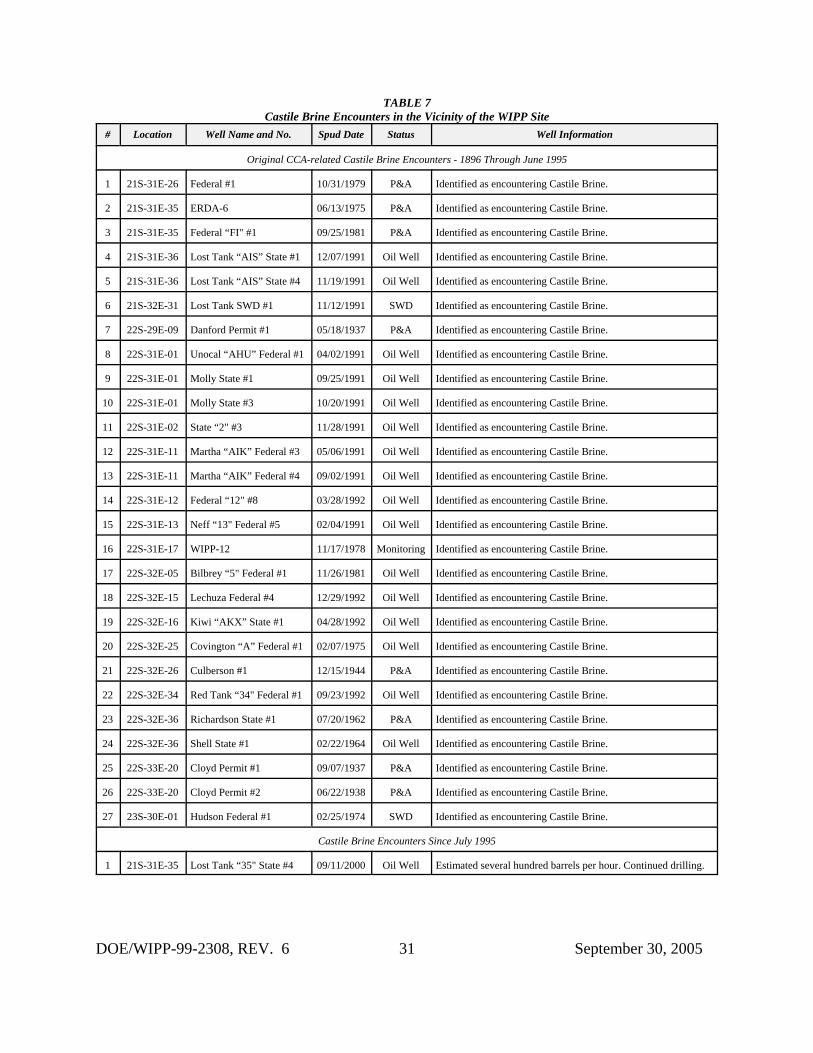
WIPP PA included the assumption that a borehole results in the establishment of a flow pathbetween the repository and a pressurized brine pocket that might be located beneath therepository in the Castile Formation. Research was performed in an attempt to verify thisassumption. Studies recorded a total of 27 out of 620 wells ecountering pressurized brine in theCastile Formation; of these, 25 were hydrocarbon wells scattered over a wide area in the vicinityof the WIPP Site. The remaining wells, ERDA 6 and WIPP 12, were drilled in support of WIPPSite characterization.
DOE/WIPP-99-2308, REV. 6 9 September 30, 2005
As indicated earlier, the search of the records performed in 1999 for instances of air drilling alsolooked for instances of pressurized brine. Although the search of the records noted a number ofinstances of encounters with sulfur water and brine water, none but the original 27 were found tohave been pressurized brine encounters in the Castile Formation.
The DBDSP researches the well files of all new wells drilled in the New Mexico portion of theDelaware Basin each year looking for instances of encounters with pressurized brine. Theprogram also sends out an annual survey to operators of new wells asking if they encounteredpressurized brine during the drilling process. As of this report, none of the records reviewedindicated encounters with pressurized brine during the drilling of new wells spudded in the NewMexico portion of the Delaware Basin between September 2004 and August 2005.
Seven of the 497 wells drilled since the 1996 CCA have encountered Castile Brine. Six werepicked up when WIPP Site personnel performing field work talked to area drillers. The otherencounter was reported by an operator in the Annual Survey of area drillers. All the newencounters have been in areas where Castile Brine is expected to be encountered during thedrilling process. Table 7 shows all known Castile Brine encounters in the vicinity of the WIPPSite.
2.7 Borehole Permeability Assessment - Plugging Practices
The hydrocarbon well plugging assumptions used for the borehole permeability assessmentremain valid. The regulations in place during the submittal of the CCA and the CRA have notchanged. The assessment will not change unless the regulations change to allow a differentmethod of plugging. Regulations require the well be plugged in a manner that will permanentlyconfine all oil, gas, and water in the separate strata in which they were originally found. Theseregulations require a notice of intent to plug from the operator. This notice includes a diagram ofthe well bore and the placement of the plugs. A 24-hour notice to the NMOCD or to the Bureauof Land Management (BLM) is required before plugging may commence.
Approximately 500 wells in the vicinity of the WIPP Site in are in the KPLA. Under R-111-Pregulations, the operator is required to provide a solid cement plug through the salt section andany water-bearing horizon in addition to installing a bridge plug above the perforations. Thisrequirement provides protection to mineralized potash areas and workings by requiring acontinuous plug so that there is virtually no chance of flooding nearby mines either as they aredeveloped or during their operation.
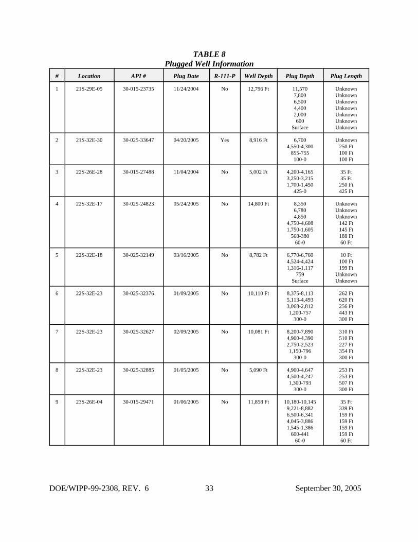
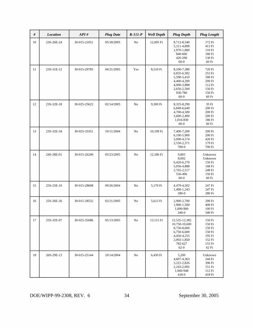
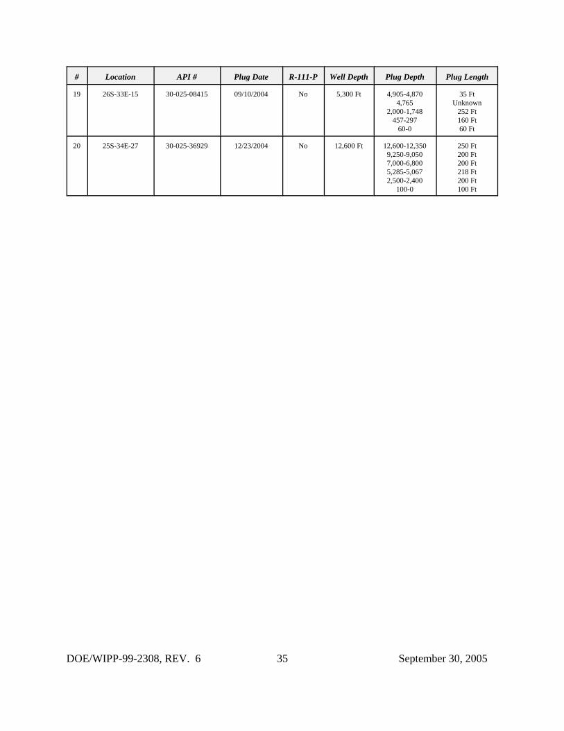
In the New Mexico portion of the Delaware Basin, the DBDSP retrieves a copy of the pluggingreport from the NMOCD Internet site when a well has been plugged and abandoned. Thisinformation is added to the records maintained by the DBDSP on each well drilled within theDelaware Basin. By maintaining records in such a fashion, should the regulations change andthe plugging methods differ from what is now occurring, a trend would be noticed and theborehole permeability assessment revisited. Table 8 shows various plug information on the
DOE/WIPP-99-2308, REV. 6 10 September 30, 2005
wells plugged and abandoned within the New Mexico portion of the Delaware Basin in the lastyear.
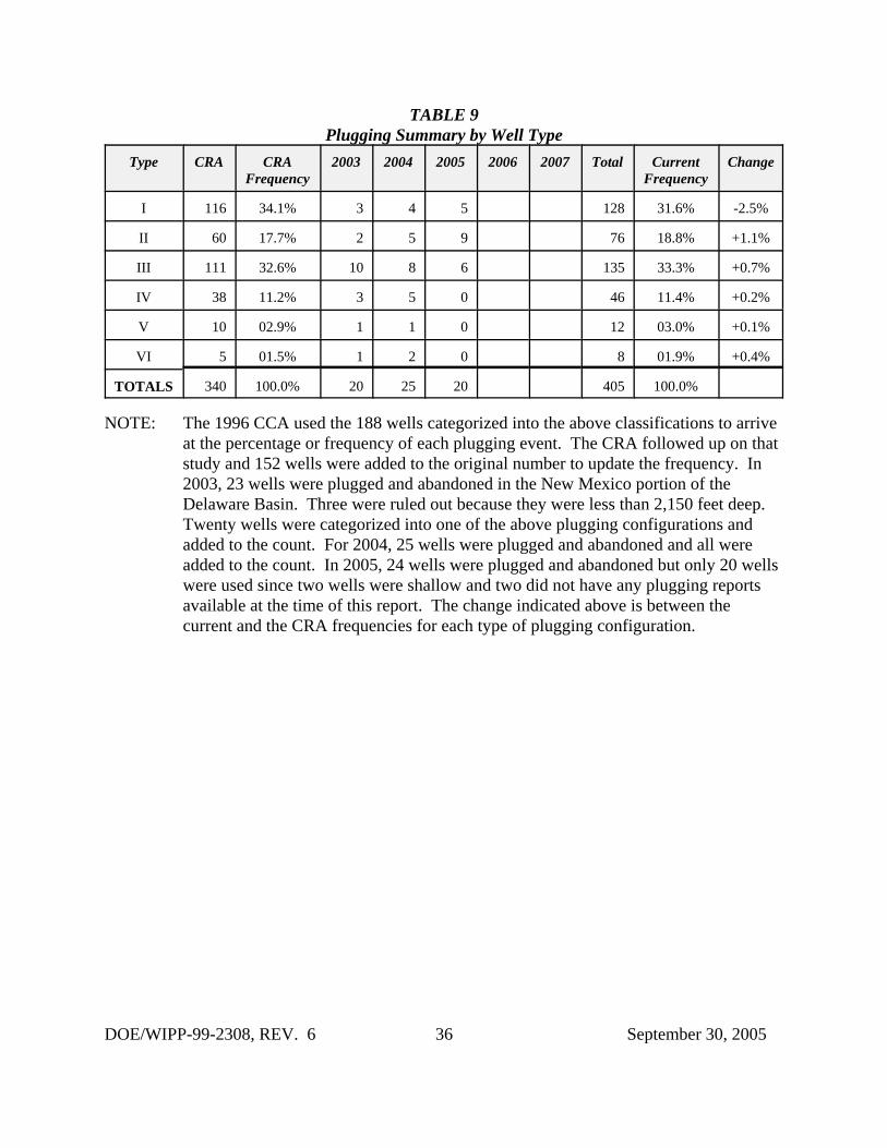
CCA Appendix MASS, Attachment 16-1 describes the development of a conceptual model forlong-term performance of plugged boreholes. The study did not attempt to predict theeffectiveness of plugs, but to identify the location and physical characteristics of plugs whichmight be important to performance assessment. Guidance in 40 CFR 194 states that“Performance assessments should assume that the permeability of sealed boreholes will beaffected by natural processes, and should assume that the fraction of boreholes that will be sealedby man equals the fraction of boreholes which are currently sealed in the Delaware Basin.” Thecriteria also state that “...drilling practices will remain as those of today.” Only wells plugged inthe New Mexico portion of the Delaware Basin were used for the study and only wells drilledafter 1988, when the current plugging regulation went into effect, were used. The results of thisstudy indicated that PA should assume a 100% plugging frequency.
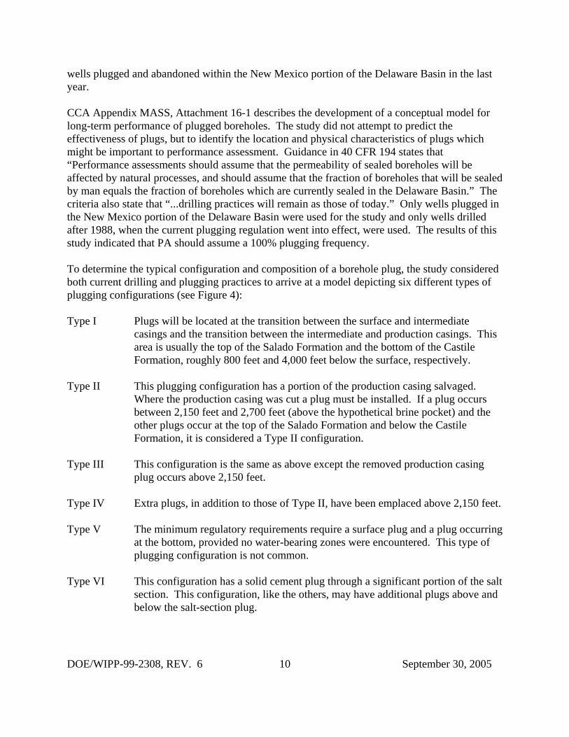
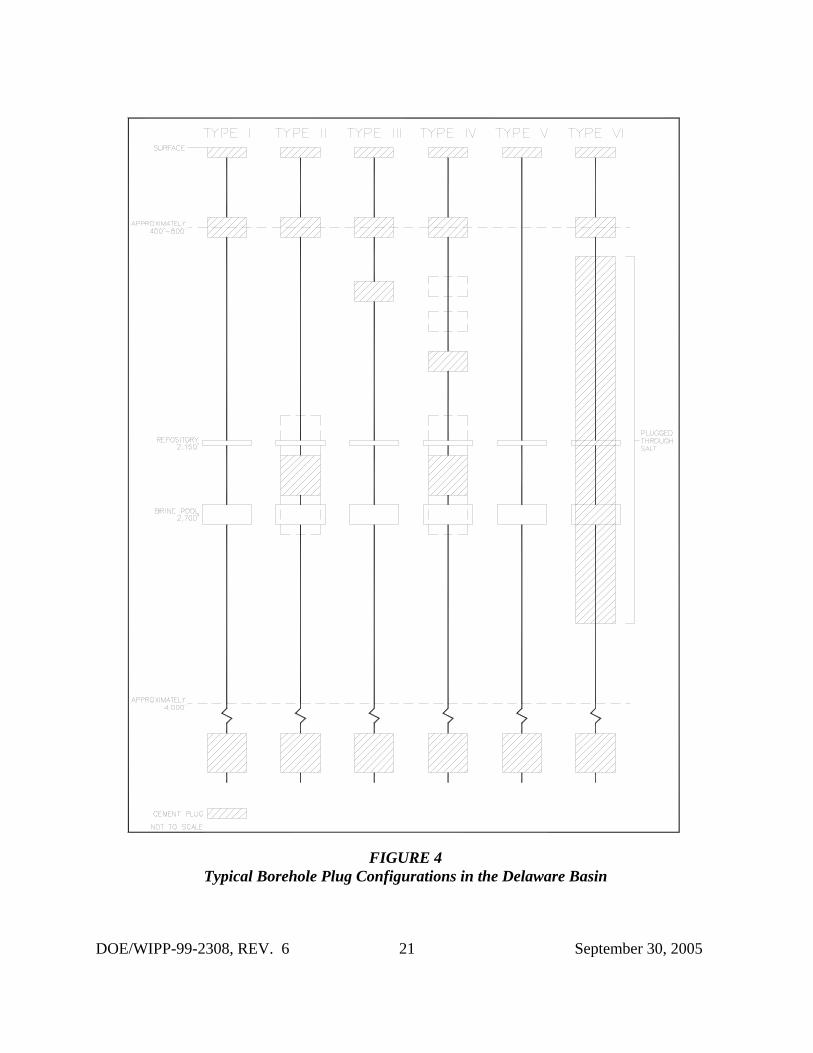
To determine the typical configuration and composition of a borehole plug, the study consideredboth current drilling and plugging practices to arrive at a model depicting six different types ofplugging configurations (see Figure 4):
Type I Plugs will be located at the transition between the surface and intermediatecasings and the transition between the intermediate and production casings. Thisarea is usually the top of the Salado Formation and the bottom of the CastileFormation, roughly 800 feet and 4,000 feet below the surface, respectively.
Type II This plugging configuration has a portion of the production casing salvaged. Where the production casing was cut a plug must be installed. If a plug occursbetween 2,150 feet and 2,700 feet (above the hypothetical brine pocket) and theother plugs occur at the top of the Salado Formation and below the CastileFormation, it is considered a Type II configuration.
Type III This configuration is the same as above except the removed production casingplug occurs above 2,150 feet.
Type IV Extra plugs, in addition to those of Type II, have been emplaced above 2,150 feet.
Type V The minimum regulatory requirements require a surface plug and a plug occurringat the bottom, provided no water-bearing zones were encountered. This type ofplugging configuration is not common.
Type VI This configuration has a solid cement plug through a significant portion of the saltsection. This configuration, like the others, may have additional plugs above andbelow the salt-section plug.
DOE/WIPP-99-2308, REV. 6 11 September 30, 2005
There were nine hydrocarbon wells, with two located in the R-111-P area, plugged in the nine-township area during the reporting period and 16 others outside the nine-township area. Twentyof the 24 wells will be used in the permeability assessment update (see Table 9). Two wereshallow wells and two had no plugging reports available at the time of this report.
2.8 Seismic Activity in the Delaware Basin
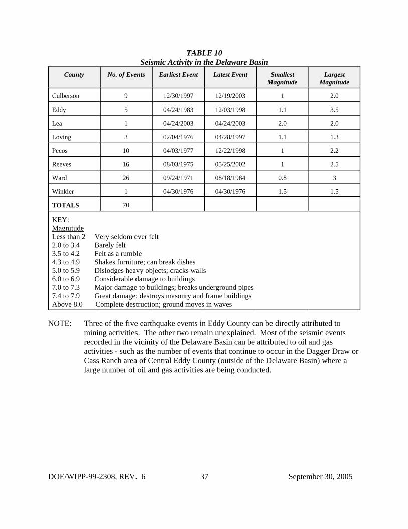
The DBDSP records in a database and on a map known seismic events occurring in SoutheastNew Mexico and West Texas, specifically in the Delaware Basin. This information is providedevery quarter in a report from New Mexico Institute of Mining and Technology, Socorro, NewMexico, utilizing data from an array of nine seismographs in the vicinity of the WIPP Site.
During the reporting period there were no seismic events recorded in the Delaware Basin. Table10 provides information on recorded events which have occurred in the Delaware Basin.
2.9 Secondary and Tertiary Recovery
Secondary recovery is defined by the oil industry as the first improved recovery method of anytype applied to a reservoir to produce oil not recoverable by primary recovery methods. Water-flooding is one such method. This method involves pumping water through the existingperforations in a well. As the water is pumped into a formation, it stimulates production of oil orgas in other nearby wells. This is a proven method of recovering hydrocarbons that otherwisewould be economically unretrievable. Waterflooding has been a popular form of secondaryrecovery for over 40 years. Waterflooding can be accomplished by one injection well or severalinjection wells in the immediate vicinity of other producing wells.
In the New Mexico portion of the Delaware Basin, there are three major waterflood projects andseveral one and two injection well operations. One of the major waterflood projects in the areais the El Mar, located in T26S-R32E, on the Texas border. At one time, this project (currentlyoperated by Sahara Operating) had 31 permitted injection wells. Currently, there are only twowells actively injecting water. The remaining wells are either shut-in or plugged and abandoned. The operation for the El Mar project has not changed during the last year. The Paducawaterflood project, located in T25S-R32E, has 19 permitted injection wells with ten (same as lastyear) injecting water into the formation. The third major waterflood project in this area (IndianDraw), located in T22S-R28E, is currently injecting into six of its permitted wells. At this timelast year, this facility was not injecting into any of the ten permitted wells.
Tertiary recovery is defined by the oil industry as the use of any improved recovery method toremove additional oil after secondary recovery. One method of tertiary recovery practiced in theindustry, where conditions permit, is the injection of carbon dioxide (CO2) into the formation. This consists of injecting a prescribed amount of CO2 into the reservoir followed by an injectionof water and a subsequent injection of CO2. At the time of this report, there are no known CO2injection wells or tertiary recovery projects being operated in the vicinity of the WIPP Site,
DOE/WIPP-99-2308, REV. 6 12 September 30, 2005
although several are being operated by oil companies in the Texas portion of the DelawareBasin.
2.9.1 Nine-Township Injection Wells
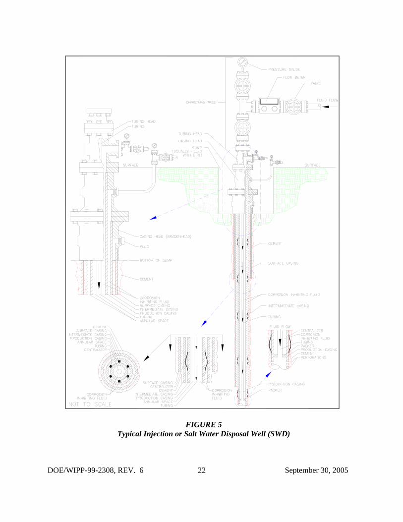
Secondary recovery projects occurring in the nine-township area are on a small scale. There aresix injection wells, no change from this time last year, located in the nine-township areasurrounding the WIPP Site. ConocoPhillips operates two injection wells, James “A” #3 and #12,located in section 2-T22S-R30E, northwest of the site. Both are active and injecting an averageof 46,000 bbls per month. Both first injected water in the early 1990s. The other four injectionwells are operated by Pogo Producing Company. The Neff Federal #3 is located in section 25-T22S-R31E. This well went on-line in 1995 and has injected approximately 5,792,020 barrels(4,971,521 barrels this time last year) of water at an average of 68,000 bbls per month. The PureGold “B” Federal #20 (23S-31E-20) has injected 808,517 barrels to date. The third Pogo well(Prize Federal #4 located in 22S-32E-27) has injected 833,362 barrels to date. The fourth Pogowell (State “2" #5 located in 22S-31E-02) was permitted in 2003 and recently began injecting. Ithas injected 288,582 barrels to date. All six wells are injecting into the Brushy CanyonFormation of the Delaware Mountain Group at a depth of approximately 7,200 feet. Figure 5shows a typical injection or salt water disposal well configuration.
2.9.2 Nine-Township Salt Water Disposal Wells
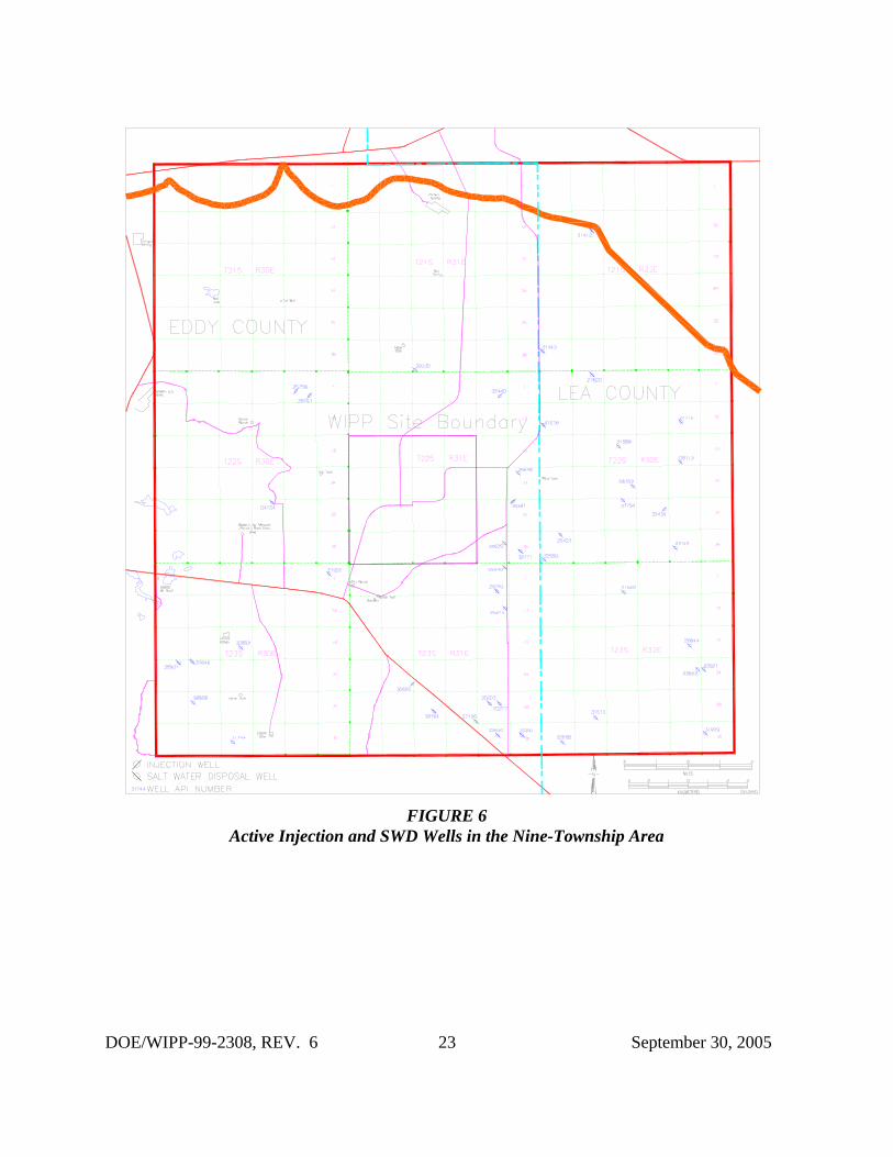
The most common type of injection well is for the disposal of brine water coming from theproducing formation in oil and gas wells. Figure 6 shows the location of active injection and saltwater disposal wells in the nine-township area. Most producing oil and gas wells produce wateralong with oil or gas. Salt Water Disposal (SWD) wells have become necessary as a result of theEPA’s ruling that formation water may no longer be disposed of on the surface. The oilcompanies now dispose of this water by injecting it into approved SWD wells.
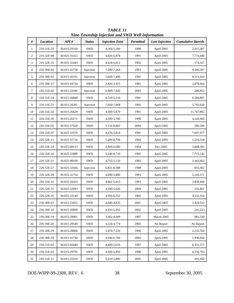
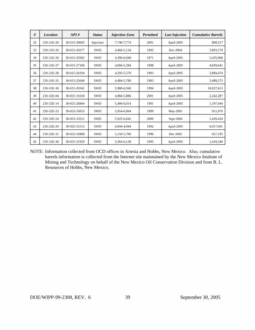
There are currently 39 SWD wells, an increase of three over the last year, operated by 13companies (12 companies in 2004) located in the nine-township area surrounding the WIPP Site. Two operators, Devon Energy and Pogo Producing, operate the majority of the SWD wells. Injection depths range from 3,800 feet to 8,200 feet. During the last year, all operated withintheir maximum permitted injection pressure. The volume of disposed brine water depends on thenumber of producing wells maintained by the operator in the immediate vicinity of the SWDwell. Table 11 provides disposal information on all SWD and injection wells in the nine-township area.
2.10 Pipeline Activity
Pipeline activity is monitored in the nine-township area, specifically within a five mile radius ofthe WIPP Site. Only pipelines of permanent construction, such as buried rigid metal pipelines,are of concern to the DBDSP. Many oil, gas, and SWD wells are connected to tank batteries bygathering systems constructed of poly flowlines (flexible plastic pipe) that may or may not be
DOE/WIPP-99-2308, REV. 6 13 September 30, 2005
buried. These flowlines are semi-permanent. When they are no longer needed, they areremoved for use elsewhere. This type of pipeline activity is not monitored by the DBDSP. Metal pipeline activity is of interest because of its longevity thus requiring the locations of thesepipelines to be documented. Only natural gas and water pipelines are located within theimmediate vicinity of the WIPP Site. The natural gas pipelines are owned and operated by threecompanies, El Paso Natural Gas Company, Natural Gas Pipeline Company of America, andTranswestern Pipeline Company.
One type of pipeline activity of major concern to the DBDSP is CO2 pipelines. A form oftertiary recovery of oil, discussed previously, uses CO2. An indicator of this form of recoverywould be the construction of a CO2 pipeline in the area. Currently, there are no CO2 pipelineswithin the New Mexico portion of the Delaware Basin. The nearest CO2 pipeline is locatedsouth of the WIPP Site in the Texas portion of the Delaware Basin.
2.11 Mining
Resources found in the Delaware Basin that can be mined are potash, sulfur, caliche, gypsum,and halite. Potash and sulfur are present in quantities large enough to be mined profitably. Onlycaliche, of the other resources available, is economically extracted from the earth in conventionalmining methods. Caliche is mainly used in the construction of pads for oil and gas well drillingrigs.
2.11.1 Potash Mining
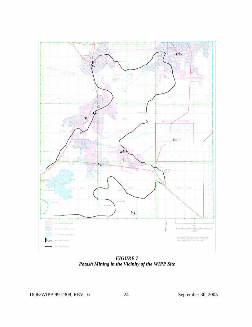
Potash mining in the immediate vicinity of the WIPP Site continues as reported in AppendixDEL of the CCA and Appendix DATA of the CRA. Figure 7 shows the location and the extentof the potash mines in the vicinity of the WIPP Site. There have been several changes to thecompanies that operate in the area, most notably, only two potash mining companies remain inoperation. No plans have been promulgated by either company to sink new shafts or developnew mines.
In August 1996, Mississippi Potash (a subsidiary of Mississippi Chemical Corporation)purchased all the assets of New Mexico Potash Corporation and Eddy Potash, Inc. These plantswere renamed Mississippi East and Mississippi North, respectively. In early 2004, MississippiPotash sold its Carlsbad properties to Intrepid Mining LLC, a Denver based mining company. Eddy Potash is currently shut down.
The other potash producer in the area is Mosaic, formerly known as IMC Kalium Potash, whichwas a wholly-owned subsidiary of IMC Global. Western Ag-Minerals was purchased by IMCGlobal September 1997. This acquisition doubled the potash reserves for IMC Kalium. IMCGlobal merged with Freeport-McMoRan, a major world potash producer, in December 1997with IMC Global as the surviving entity in the transaction.
DOE/WIPP-99-2308, REV. 6 14 September 30, 2005
2.11.2 Sulfur Extraction
The only viable sulfur mining activity within the Delaware Basin was conducted by Freeport-McMoRan Sulphur, Inc., a wholly-owned subsidiary of McMoRan Exploration Company. Themine is located in Culberson County, Texas. The mine recovered sulfur utilizing the Fraschprocess (solution mining) which consists of a hole drilled into the sulfur bearing formation andthen cased. The next step involves the placement of three concentric pipes within the protectivecasing to facilitate pumping superheated water down the hole, melting the sulfur, and recoveringthe molten sulfur to the surface. The Culberson mine was operated until it permanently ceasedproduction on June 30, 1999. Abandonment and salvage operations continued until earlysummer of 2000.
Recently, a number of sulfur exploration coreholes were found in the BLM records. Thesecoreholes were drilled in the late 1960s through the early 1980s in the Yeso Hills nearWashington Ranch in the far southwest corner of the New Mexico portion of the DelawareBasin. These coreholes have yet to be added to the databases. All were shallow (less than 2,150feet) drilling events that were conducted for various small operators. There have been no reportson whether any of the holes encountered sufficient quantities of mineable sulfur.
2.11.3 Solution Mining
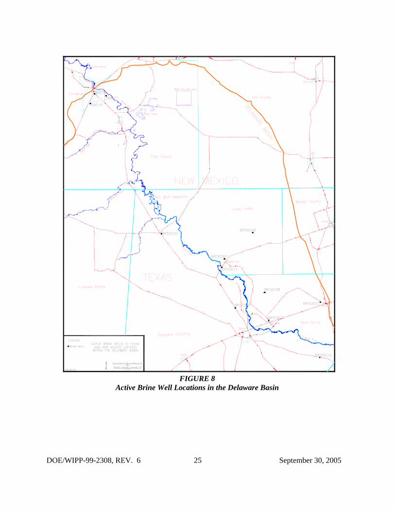
Solution mining is the process by which water is injected into a mineral formation, circulated todissolve the mineral, with the solution then pumped back to the surface where the minerals areremoved from the water, usually by evaporation. There are several brine mines or wells in thearea, three in New Mexico and nine in Texas (see Figure 8), that use this process to provide abrine solution for area drilling operators to use in the drilling process. These are all shallowwells using injected fresh water to dissolve salt into a brine solution.
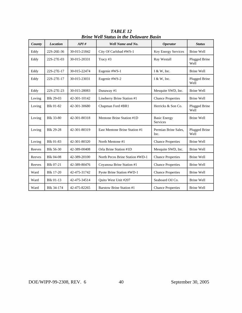
Brine wells are classified as Class II injection wells. In the Delaware Basin, the process involvesinjecting fresh water through the wells into a salt formation to create a saturated brine solution,which is then extracted and used as a drilling agent when drilling a new well. These wells aretracked by the DBDSP on a continuing basis. Recently, while investigating the status of an idleSalt Water Disposal well at the OCD office, records were found within the file for the idle well,which indicated the presence of a permitted brine well (for retrieval) and an injection well toinject fresh water into the salt formation. The DBDSP records have been updated to list thesenew wells. Table 12 provides the status of brine wells in the Delaware Basin.
In early 1997, Mississippi Potash proposed to set up a pilot potash solution mining project at theformer Eddy Potash mine located north of the WIPP Site and outside of the Delaware Basin. The BLM was provided with all of the necessary documentation to acquire a permit to operatethe pilot project, but the project was postponed. In March 2002, Mississippi Potash againapplied for a permit to operate a pilot potash solution mining project. In May 2002, the projectwas given approval to proceed by the BLM though the project has not been started. If theproject is initiated, it will be approximately three acres in size. Although this project is outside
DOE/WIPP-99-2308, REV. 6 15 September 30, 2005
of the Delaware Basin, it will be closely followed because of its importance to possible futureactivities of this kind that might occur in the Delaware Basin. There has been no change in thestatus of this project, it is still on hold. The new owner of Mississippi Potash, Intrepid MiningLLC, is reviewing its options for this project.
In the late 1960s, Conoco Minerals installed a pilot solution mining project on leases it held onthe former AMAX property north of the Delaware Basin and the WIPP Site. The project wasdesigned to test solution mining of potassium minerals and consisted of one injection well andthree withdrawal wells, but the potash ore zone was deemed too thin to make this method viable.
2.12 New Drilling Technology
New drilling methods are researched by the DBDSP for impacts to the drilling methods currentlyused in the area. To date, no new methods of drilling have been identified or implemented in thevicinity of the WIPP Site.
3.0 Survey of Well Operators for Drilling Information
The WIPP Project surveys local well operators annually to acquire information on drillingpractices normally not available on the Sundry notices supplied to the local state and federaloffices by the operator or through commercial sources maintained by the DBDSP. Participationin the survey is voluntary. This survey requests information on other items of interest to theWIPP such as hydrogen sulfide (H2S) encounters, Castile Brine encounters, or whether anysection of the well was drilled with air. The DBDSP personnel review the records on all newwells drilled to look for the above data. The survey provides an additional source of informationon drilling activities in the New Mexico portion of the Delaware Basin.
The first survey of area operators was performed July 1999 and had been sent out each July until2004. An annual survey was not performed in July 2004 due to schedule conflicts with theCompliance Recertification Application. The survey for 2004 was moved to January 2005 andwill be performed in January of each year. With this change, all results from the annual surveywill be included in the annual report for that year as there will be nine months for surveys to bereturned instead of two months.
In January 2005, 48 surveys were sent to six companies who had wells drilled during 2004 in thenine-township area immediately surrounding the WIPP Site. To date, no surveys have beenreturned. The following companies were mailed surveys: Bass Enterprises Production Co, YatesPetroleum Corporation, Devon Energy Production Company LP, Echo Production Inc., HarvardPetroleum, and Pogo Producing Co.
DOE/WIPP-99-2308, REV. 6 16 September 30, 2005
4.0 Summary - 2005 Delaware Basin Drilling Surveillance Program
• Drilling practices continue to be the same.
• No new instances of air drilling.
• One Castile Brine encounter reported.
• The drilling rate has increased to 55.5 boreholes per square kilometer.
• IMC Kalium Potash changed its name to Mosaic.
• No change in solution mining activities.
• No change in injection and salt water disposal activities.
• Forty-four wells spudded in the nine-township area.
• One hundred sixty wells spudded outside the nine-township area in New Mexico.
• One hundred sixty-three wells spudded in the Texas portion of the Delaware Basin.
DOE/WIPP-99-2308, REV. 6 17 September 30, 2005
5.0 References
B. L. Resources, Monthly Injection & Saltwater Report for Southeast New Mexico, April 2005
New Mexico Bureau of Mines and Mineral Resources, 1995, Evaluation of Mineral Resources atthe Waste Isolation Pilot Plant, Final Report, Vols. I-IV
New Mexico Institute of Mining and Technology, Seismicity of the WIPP Site for the PeriodApril 1, 2005 through June 30, 2005, Socorro, New Mexico
New Mexico Junior College, 1995, Analytical Study of an Inadvertent Intrusion of the WIPPSite, Hobbs, New Mexico
Ross Kirkes, Current Drilling Practices Near WIPP, 1998. EPA Air Docket No. A-93-02, IV-G-7, January 22, 1998
The University of Texas, Petroleum Extension Service, Division of Continuing Education, 1986,Fundamentals of Petroleum, Third Edition
The University of Texas, Petroleum Extension Service, Division of Continuing Education, 1991,A Dictionary for the Petroleum Industry, First Edition
U.S. Department of Energy, DOE/WIPP-99-2308, Rev. 5, Delaware Basin Monitoring AnnualReport, September 2004
U.S. Department of Energy, 1996, Inadvertent Intrusion Borehole Permeability, Prepared byT.W. Thompson, W.E. Coons, J.L. Krumhansl, and F.D. Hansen
U.S. Department of Energy, DOE/WIPP-97-2240, Injection Methods: Current Practices andFailure Rates in the Delaware Basin, June 1997
U.S. Department of Energy, DOE/CAO-1996-2184, Title 40 CFR Part 191 ComplianceCertification Application for the Waste Isolation Pilot Plant, October 1996
U.S. Department of Energy, DOE/WIPP 2004-3231, Title 40 CFR Part 191 ComplianceRecertification Application for the Waste Isolation Pilot Plant, March 2004
U.S. Environmental Protection Agency (EPA), 1996. Title 40 CFR Part 194, Criteria for theCertification and Re-Certification of the Waste Isolation Pilot Plant’s Compliance with the 40CFR Part 191 Disposal Regulations
Washington TRU Solutions LLC, WP 02-PC.02, Rev. 1, Delaware Basin Drilling SurveillancePlan, July 2004
DOE/WIPP-99-2308, REV. 6 18 September 30, 2005
FIGURE 1WIPP Site, Delaware Basin, and Surrounding Area
DOE/WIPP-99-2308, REV. 6 19 September 30, 2005
FIGURE 2Typical Well Structure and General Stratigraphy Near the WIPP Site
DOE/WIPP-99-2308, REV. 6 20 September 30, 2005
FIGURE 3Oil and Gas Wells Within One Mile of the WIPP Site
DOE/WIPP-99-2308, REV. 6 21 September 30, 2005
FIGURE 4Typical Borehole Plug Configurations in the Delaware Basin
DOE/WIPP-99-2308, REV. 6 22 September 30, 2005
FIGURE 5Typical Injection or Salt Water Disposal Well (SWD)
DOE/WIPP-99-2308, REV. 6 23 September 30, 2005
FIGURE 6Active Injection and SWD Wells in the Nine-Township Area
DOE/WIPP-99-2308, REV. 6 24 September 30, 2005
FIGURE 7Potash Mining in the Vicinity of the WIPP Site
DOE/WIPP-99-2308, REV. 6 25 September 30, 2005
FIGURE 8Active Brine Well Locations in the Delaware Basin
DOE/WIPP-99-2308, REV. 6 26 September 30, 2005
TABLE 1Nine-Township Area Casing Sizes
Casing Size Surface Casing Intermediate Casing Production Casing
13 d” 34 0 0
11 ¾” 0 0 0
9 e” 0 3 0
8 e” 0 31 0
7” 0 0 3
5 ½” 0 0 31
NOTE: There were 44 wells drilled in the nine-township area between September 1, 2004 andAugust 31, 2005. Thirty-four of the wells had complete records available on casingsizes. The other 10 wells had partial records available or had just recently beenspudded.
TABLE 2Nine-Township Area Bit Sizes
Bit Size Surface Hole Intermediate Hole Production Hole
17 ½” 34 0 0
14 ¾” 0 0 0
12 ¼” 0 3 0
11” 0 31 0
8 ¾" 0 0 3
7 f” 0 0 31
NOTE: Of the 44 wells drilled in the nine-township area, complete records were available on34 wells. The other 10 wells did not have records available on bit sizes.
DOE/WIPP-99-2308, REV. 6 27 September 30, 2005
TABLE 3Air-Drilled Wells in the New Mexico Portion of the Delaware Basin
# Location Well Name and No. Spud Date Status Well Information
Wells Drilled Prior to Submittal of the 1996 CCA With Some Portion Drilled by Air.
1 21S-28E-33 Richardson & Bass #1 07/27/1961 P&A Air drilled through the salt. Between2,545' and 2,685' encountered water andchanged from air to mud-based drilling.
2 21S-32E-26 Lincoln Federal Unit #1 04/01/1991 P&A Lost circulation at 1,290'. Hole was drydrilled to 1,792'. Supposedly, air drilledfrom 2,984' to 4,725'.
3 23S-26E-17 Exxon “17" Federal #1 08/01/1989 Gas Well Air drilled through the salt from 575' to2,707'.
4 23S-28E-11 CP Pardue #1 10/28/1958 P&A Air drilled through the salt from 390' to2,620'.
5 23S-28E-11 Amoco Federal #1 08/04/1979 Oil Well Air drilled from 475' to 9,700'.
6 23S-28E-11 Amoco Federal #3 02/28/1980 Oil Well Air drilled from 6,271' to 9,692'.
7 23S-28E-23 South Culebra Bluff Unit #3 01/21/1979 Oil Well Air drilled from 6,345' to 8,000'.
8 23S-28E-23 South Culebra Bluff Unit #4 08/09/1979 Oil Well Air drilled from 450' to 9,802'.
9 24S-31E-03 Lilly “ALY” Federal #2 05/01/1994 Oil Well Air drilled conductor hole to 40'.
10 24S-31E-03 Lilly “ALY” Federal #4 05/16/1994 Oil Well Air drilled conductor hole to 40'.
11 24S-34E-04 Antelope Ridge Unit #2 09/13/1962 Gas Well Attempted to drill with gas. Had toconvert to water at 1,035'. Tried againseveral times at different depths.
12 24S-34E-09 Federal “9" Com #1 12/03/1963 Gas Well Hit water while gas drilling at 4,865'.
13 24S-34E-13 Federal Johnson #1 06/23/1958 P&A Proposed to drill with air, but noinformation in the records indicate airdrilling.
14 26S-32E-20 Russell Federal #1 03/16/1966 Oil Well Drilled with air to 1,330'.
15 26S-32E-36 North El Mar Unit #44 02/19/1959 Oil Well Proposed to drill with air, but noinformation in the records indicate airdrilling.
Wells Drilled after Supplemental Information Provided to the EPA Docket in 1997.
16 22S-26E-28 Sheep Draw “28" Federal #13 07/01/1997 Oil Well Air drilled the first 358'.
NOTE: The research on “air drilling” is a continuous effort since every new well drilled is checked todetermine if any portion of the well was drilled by air. A copy of all completion reports are onfile for all wells completed within the New Mexico portion of the Delaware Basin.
DOE/WIPP-99-2308, REV. 6 28 September 30, 2005
TABLE 4Shallow Well Status in the Delaware Basin
Well Type Texas New Mexico Totals
Core Hole 31 2 33
Dry Hole 325 146 471
Gas Well 8 3 11
Injection Well 5 0 5
Junked and Abandoned Well 61 29 90
Oil Well 88 7 95
Oil and Gas Well 1 0 1
Plugged Gas Well 1 2 3
Plugged Oil Well 14 14 28
Plugged Brine Well 2 1 3
Plugged Salt Water Disposal Well 0 4 4
Drilling or Waiting on Paperwork 147 83 230
Brine Well 1 4 5
Salt Water Disposal Well 0 1 1
Service Well 13 0 13
Stratigraphic Test Hole 1,170 0 1,170
Sulfur Core Hole 502 0 502
Potash Core Hole 0 992 992
Water Well 1,706 590 2,296
WIPP Well 0 192 192
Other (Mine Shafts, Gnome Project Wells) 0 44 44
TOTALS 4,075 2,114 6,189
NOTE: Only the known holes that occur in the Delaware Basin, except several WIPP holes, are listed inthe above table. The WIPP holes are shown for completeness. The 230 wells under the listing of“Drilling or Waiting on Paperwork” do not have an associated depth until one has been reportedon paperwork. These are listed as shallow wells but may eventually be placed in the deepclassification when a depth has been listed in the paperwork.
DOE/WIPP-99-2308, REV. 6 29 September 30, 2005
TABLE 5Deep Well Status in the Delaware Basin
Well Type Texas New Mexico Totals
Core Hole 5 0 5
Dry Hole 2,185 841 3,026
Gas Well 904 737 1,641
Injection Well 241 66 307
Junked and Abandoned Well 58 18 76
Oil Well 3,811 2,062 5,873
Oil and Gas Well 86 5 91
Plugged Gas Well 187 149 336
Plugged Injection Well 37 30 67
Plugged Oil Well 608 330 938
Plugged Oil and Gas Well 35 0 35
Plugged Brine Well 0 1 1
Plugged Salt Water Disposal Well 3 12 15
Plugged Service Well 2 0 2
Drilling or Waiting on Paperwork 14 1 15
Brine Well 8 0 8
Salt Water Disposal Well 7 110 117
Service Well 97 2 99
Stratigraphic Test Hole 44 2 46
Sulfur Core Hole 85 0 85
Potash Core Hole 0 19 19
WIPP Well 0 11 11
Other (Mine Shafts, Gnome Project Wells) 0 6 6
TOTALS 8,417 4,402 12,819
NOTE: The 15 wells under the category of “Drilling or Waiting on Paperwork” have a depth associatedwith them which classifies them as deep wells, but the paperwork classifying these wells as oil,gas, or some other type of well have yet to be posted. When posted, the classification of thesetypes of wells will be changed.
DOE/WIPP-99-2308, REV. 6 30 September 30, 2005
TABLE 6Past Drilling Rates for the Delaware Basin
Year No. of Deep Holes Drilling Rate
1996 10,804 Holes Deeper Than 2,150 Ft 46.8
1997 11,444 Holes Deeper Than 2,150 Ft 49.5
1998 11,616 Holes Deeper Than 2,150 Ft 50.3
1999 11,684 Holes Deeper Than 2,150 Ft 50.6
2000 11,828 Holes Deeper Than 2,150 Ft 51.2
2001 12,056 Holes Deeper Than 2,150 Ft 52.2
20021 12,139 Holes Deeper Than 2,150 Ft 52.5
2003 12,316 Holes Deeper Than 2,150 Ft 53.3
2004 12,531 Holes Deeper Than 2,150 Ft 54.2
Note: The notable increase in the drilling rate between 1996 and 1997 was not due to thedrilling of wells, but to the fact that the Delaware Basin Drilling Surveillance Programwas not began until 1997 when a review of the records from July 1995 through 1997 wasnecessary to bring the databases up to date. Since that time, the drilling rate has risenapproximately the same each year.
1 In Rev. 3 of this report dated September 2002, the drilling rate for 2002 was shown as52.9 with 12,219 deep holes. While reviewing the databases to develop reports for theCompliance Recertification Application, it was noticed that 80 shallow wells in Texaswere listed as being deep. Several days investigation found the problem, and it wascorrected. Correcting the classification of the 80 holes to shallow resulted in a reductionin the drilling rate from 52.9 to 52.5. This was reported in December 2002.
DOE/WIPP-99-2308, REV. 6 31 September 30, 2005
TABLE 7Castile Brine Encounters in the Vicinity of the WIPP Site
# Location Well Name and No. Spud Date Status Well Information
Original CCA-related Castile Brine Encounters - 1896 Through June 1995
1 21S-31E-26 Federal #1 10/31/1979 P&A Identified as encountering Castile Brine.
2 21S-31E-35 ERDA-6 06/13/1975 P&A Identified as encountering Castile Brine.
3 21S-31E-35 Federal “FI" #1 09/25/1981 P&A Identified as encountering Castile Brine.
4 21S-31E-36 Lost Tank “AIS” State #1 12/07/1991 Oil Well Identified as encountering Castile Brine.
5 21S-31E-36 Lost Tank “AIS” State #4 11/19/1991 Oil Well Identified as encountering Castile Brine.
6 21S-32E-31 Lost Tank SWD #1 11/12/1991 SWD Identified as encountering Castile Brine.
7 22S-29E-09 Danford Permit #1 05/18/1937 P&A Identified as encountering Castile Brine.
8 22S-31E-01 Unocal “AHU” Federal #1 04/02/1991 Oil Well Identified as encountering Castile Brine.
9 22S-31E-01 Molly State #1 09/25/1991 Oil Well Identified as encountering Castile Brine.
10 22S-31E-01 Molly State #3 10/20/1991 Oil Well Identified as encountering Castile Brine.
11 22S-31E-02 State “2" #3 11/28/1991 Oil Well Identified as encountering Castile Brine.
12 22S-31E-11 Martha “AIK” Federal #3 05/06/1991 Oil Well Identified as encountering Castile Brine.
13 22S-31E-11 Martha “AIK” Federal #4 09/02/1991 Oil Well Identified as encountering Castile Brine.
14 22S-31E-12 Federal “12" #8 03/28/1992 Oil Well Identified as encountering Castile Brine.
15 22S-31E-13 Neff “13" Federal #5 02/04/1991 Oil Well Identified as encountering Castile Brine.
16 22S-31E-17 WIPP-12 11/17/1978 Monitoring Identified as encountering Castile Brine.
17 22S-32E-05 Bilbrey “5" Federal #1 11/26/1981 Oil Well Identified as encountering Castile Brine.
18 22S-32E-15 Lechuza Federal #4 12/29/1992 Oil Well Identified as encountering Castile Brine.
19 22S-32E-16 Kiwi “AKX” State #1 04/28/1992 Oil Well Identified as encountering Castile Brine.
20 22S-32E-25 Covington “A” Federal #1 02/07/1975 Oil Well Identified as encountering Castile Brine.
21 22S-32E-26 Culberson #1 12/15/1944 P&A Identified as encountering Castile Brine.
22 22S-32E-34 Red Tank “34" Federal #1 09/23/1992 Oil Well Identified as encountering Castile Brine.
23 22S-32E-36 Richardson State #1 07/20/1962 P&A Identified as encountering Castile Brine.
24 22S-32E-36 Shell State #1 02/22/1964 Oil Well Identified as encountering Castile Brine.
25 22S-33E-20 Cloyd Permit #1 09/07/1937 P&A Identified as encountering Castile Brine.
26 22S-33E-20 Cloyd Permit #2 06/22/1938 P&A Identified as encountering Castile Brine.
27 23S-30E-01 Hudson Federal #1 02/25/1974 SWD Identified as encountering Castile Brine.
Castile Brine Encounters Since July 1995
1 21S-31E-35 Lost Tank “35" State #4 09/11/2000 Oil Well Estimated several hundred barrels per hour. Continued drilling.
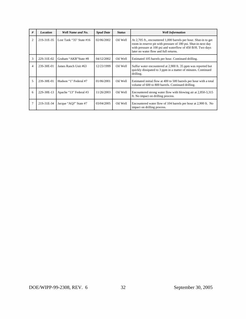
# Location Well Name and No. Spud Date Status Well Information
DOE/WIPP-99-2308, REV. 6 32 September 30, 2005
2 21S-31E-35 Lost Tank “35" State #16 02/06/2002 Oil Well At 2,705 ft., encountered 1,000 barrels per hour. Shut-in to getroom in reserve pit with pressure of 180 psi. Shut-in next daywith pressure at 100 psi and waterflow of 450 B/H. Two dayslater no water flow and full returns.
3 22S-31E-02 Graham “AKB”State #8 04/12/2002 Oil Well Estimated 105 barrels per hour. Continued drilling.
4 23S-30E-01 James Ranch Unit #63 12/23/1999 Oil Well Sulfur water encountered at 2,900 ft. 35 ppm was reported butquickly dissipated to 3 ppm in a matter of minutes. Continueddrilling.
5 23S-30E-01 Hudson “1" Federal #7 01/06/2001 Oil Well Estimated initial flow at 400 to 500 barrels per hour with a totalvolume of 600 to 800 barrels. Continued drilling.
6 22S-30E-13 Apache “13" Federal #3 11/26/2003 Oil Well Encountered strong water flow with blowing air at 2,850-3,315ft. No impact on drilling process.
7 21S-31E-34 Jacque “AQJ” State #7 03/04/2005 Oil Well Encountered water flow of 104 barrels per hour at 2,900 ft. Noimpact on drilling process.
DOE/WIPP-99-2308, REV. 6 33 September 30, 2005
TABLE 8Plugged Well Information
# Location API # Plug Date R-111-P Well Depth Plug Depth Plug Length
1 21S-29E-05 30-015-23735 11/24/2004 No 12,796 Ft 11,5707,8006,5004,4002,000600
Surface
UnknownUnknownUnknownUnknownUnknownUnknownUnknown
2 21S-32E-30 30-025-33647 04/20/2005 Yes 8,916 Ft 6,7004,550-4,300
855-755100-0
Unknown250 Ft100 Ft100 Ft
3 22S-26E-28 30-015-27488 11/04/2004 No 5,002 Ft 4,200-4,1653,250-3,2151,700-1,450
425-0
35 Ft35 Ft250 Ft425 Ft
4 22S-32E-17 30-025-24823 05/24/2005 No 14,800 Ft 8,3506,7804,850
4,750-4,6081,750-1,605
568-38060-0
UnknownUnknownUnknown
142 Ft145 Ft188 Ft60 Ft
5 22S-32E-18 30-025-32149 03/16/2005 No 8,782 Ft 6,770-6,7604,524-4,4241,316-1,117
759Surface
10 Ft100 Ft199 Ft
UnknownUnknown
6 22S-32E-23 30-025-32376 01/09/2005 No 10,110 Ft 8,375-8,1135,113-4,4933,068-2,8121,200-757
300-0
262 Ft620 Ft256 Ft443 Ft300 Ft
7 22S-32E-23 30-025-32627 02/09/2005 No 10,081 Ft 8,200-7,8904,900-4,3902,750-2,5231,150-796
300-0
310 Ft510 Ft227 Ft354 Ft300 Ft
8 22S-32E-23 30-025-32885 01/05/2005 No 5,090 Ft 4,900-4,6474,500-4,2471,300-793
300-0
253 Ft253 Ft507 Ft300 Ft
9 23S-26E-04 30-015-29471 01/06/2005 No 11,858 Ft 10,180-10,1459,221-8,8826,500-6,3414,045-3,8861,545-1,386
600-44160-0
35 Ft339 Ft159 Ft159 Ft159 Ft159 Ft60 Ft
# Location API # Plug Date R-111-P Well Depth Plug Depth Plug Length
DOE/WIPP-99-2308, REV. 6 34 September 30, 2005
10 23S-26E-24 30-015-21051 05/18/2005 No 12,005 Ft 8,712-8,5405,311-4,8981,970-1,860
840-660420-290
60-0
172 Ft413 Ft110 Ft180 Ft130 Ft60 Ft
11 23S-31E-12 30-015-29785 04/21/2005 Yes 8,510 Ft 8,100-7,3806,835-6,5825,590-5,4104,400-4,2004,000-3,8882,650-2,500
930-78060-0
720 Ft253 Ft180 Ft200 Ft112 Ft150 Ft150 Ft60 Ft
12 23S-32E-18 30-025-25622 02/14/2005 No 9,300 Ft 8,325-8,2906,849-6,6494,700-4,5002,600-2,4001,016-830
60-0
35 Ft200 Ft200 Ft200 Ft186 Ft60 Ft
13 23S-32E-34 30-025-33351 10/11/2004 No 10,199 Ft 7,400-7,2006,100-5,9005,000-4,5742,550-2,371
700-0
200 Ft200 Ft426 Ft179 Ft700 Ft
14 24S-28E-01 30-015-26249 05/23/2005 No 12,186 Ft 9,8658,002
6,420-6,2705,056-4,8882,765-2,517
556-40660-0
UnknownUnknown
150 Ft168 Ft248 Ft150 Ft60 Ft
15 25S-25E-10 30-015-28608 09/26/2004 No 5,170 Ft 4,479-4,5021,490-1,243
280-0
247 Ft247 Ft280 Ft
16 25S-26E-26 30-015-28532 02/21/2005 No 5,613 Ft 2,900-2,7001,900-1,5001,000-900
340-0
200 Ft400 Ft100 Ft340 Ft
17 25S-32E-07 30-025-35086 05/13/2005 No 13,115 Ft 12,535-12,38510,750-10,600
8,750-8,6006,750-6,6004,450-4,2552,002-1,850
782-62762-0
150 Ft150 Ft150 Ft150 Ft195 Ft152 Ft155 Ft62 Ft
18 26S-29E-13 30-015-25144 10/14/2004 No 6,450 Ft 5,2004,607-4,3633,222-2,8262,243-2,0921,060-948
418-0
Unknown244 Ft396 Ft151 Ft112 Ft418 Ft
# Location API # Plug Date R-111-P Well Depth Plug Depth Plug Length
DOE/WIPP-99-2308, REV. 6 35 September 30, 2005
19 26S-33E-15 30-025-08415 09/10/2004 No 5,300 Ft 4,905-4,8704,765
2,000-1,748457-297
60-0
35 FtUnknown
252 Ft160 Ft60 Ft
20 25S-34E-27 30-025-36929 12/23/2004 No 12,600 Ft 12,600-12,3509,250-9,0507,000-6,8005,285-5,0672,500-2,400
100-0
250 Ft200 Ft200 Ft218 Ft200 Ft100 Ft
DOE/WIPP-99-2308, REV. 6 36 September 30, 2005
TABLE 9Plugging Summary by Well Type
Type CRA CRAFrequency
2003 2004 2005 2006 2007 Total CurrentFrequency
Change
I 116 34.1% 3 4 5 128 31.6% -2.5%
II 60 17.7% 2 5 9 76 18.8% +1.1%
III 111 32.6% 10 8 6 135 33.3% +0.7%
IV 38 11.2% 3 5 0 46 11.4% +0.2%
V 10 02.9% 1 1 0 12 03.0% +0.1%
VI 5 01.5% 1 2 0 8 01.9% +0.4%
TOTALS 340 100.0% 20 25 20 405 100.0%
NOTE: The 1996 CCA used the 188 wells categorized into the above classifications to arriveat the percentage or frequency of each plugging event. The CRA followed up on thatstudy and 152 wells were added to the original number to update the frequency. In2003, 23 wells were plugged and abandoned in the New Mexico portion of theDelaware Basin. Three were ruled out because they were less than 2,150 feet deep. Twenty wells were categorized into one of the above plugging configurations andadded to the count. For 2004, 25 wells were plugged and abandoned and all wereadded to the count. In 2005, 24 wells were plugged and abandoned but only 20 wellswere used since two wells were shallow and two did not have any plugging reportsavailable at the time of this report. The change indicated above is between thecurrent and the CRA frequencies for each type of plugging configuration.
DOE/WIPP-99-2308, REV. 6 37 September 30, 2005
TABLE 10Seismic Activity in the Delaware Basin
County No. of Events Earliest Event Latest Event SmallestMagnitude
LargestMagnitude
Culberson 9 12/30/1997 12/19/2003 1 2.0
Eddy 5 04/24/1983 12/03/1998 1.1 3.5
Lea 1 04/24/2003 04/24/2003 2.0 2.0
Loving 3 02/04/1976 04/28/1997 1.1 1.3
Pecos 10 04/03/1977 12/22/1998 1 2.2
Reeves 16 08/03/1975 05/25/2002 1 2.5
Ward 26 09/24/1971 08/18/1984 0.8 3
Winkler 1 04/30/1976 04/30/1976 1.5 1.5
TOTALS 70
KEY:MagnitudeLess than 2 Very seldom ever felt2.0 to 3.4 Barely felt3.5 to 4.2 Felt as a rumble4.3 to 4.9 Shakes furniture; can break dishes5.0 to 5.9 Dislodges heavy objects; cracks walls6.0 to 6.9 Considerable damage to buildings7.0 to 7.3 Major damage to buildings; breaks underground pipes7.4 to 7.9 Great damage; destroys masonry and frame buildingsAbove 8.0 Complete destruction; ground moves in waves
NOTE: Three of the five earthquake events in Eddy County can be directly attributed tomining activities. The other two remain unexplained. Most of the seismic eventsrecorded in the vicinity of the Delaware Basin can be attributed to oil and gasactivities - such as the number of events that continue to occur in the Dagger Draw orCass Ranch area of Central Eddy County (outside of the Delaware Basin) where alarge number of oil and gas activities are being conducted.
DOE/WIPP-99-2308, REV. 6 38 September 30, 2005
TABLE 11Nine-Township Injection and SWD Well Information
# Location API # Status Injection Zone Permitted Last Injection Cumulative Barrels
1 21S-31E-33 30-015-29330 SWD 4,166-5,160 1998 April-2005 2,415,387
2 21S-32E-08 30-025-31412 SWD 4,826-5,978 1991 April-2005 7,774,440
3 21S-32E-31 30-025-31443 SWD 4,618-6,012 1992 April-2005 174,327
4 22S-30E-02 30-015-25758 Injection 7,200-7,264 1993 April-2005 9,166,207
5 22S-30E-02 30-015-26761 Injection 5,600-7,400 1991 April-2005 9,513,433
6 22S-30E-27 30-015-04734 SWD 3,820-3,915 1981 April-2005 2,878,664
7 22S-31E-02 30-015-32440 Injection 6,989-7,020 2003 April-2005 288,852
8 22S-31E-24 30-015-26848 SWD 4,519-5,110 1991 April-2005 6,184,887
9 22S-31E-25 30-015-28281 Injection 7,050-7,068 1995 April-2005 5,792,020
10 22S-31E-35 30-015-26629 SWD 4,500-5,670 1991 April-2005 11,747,882
11 22S-31E-36 30-015-26171 SWD 4,500-5,700 1998 April-2005 4,143,969
12 22S-32E-05 30-025-27620 SWD 5,150-8,602 2004 April-2005 590,590
13 22S-32E-07 30-025-31076 SWD 4,676-5,814 1991 April-2005 7,047,977
14 22S-32E-11 30-025-31716 SWD 5,200-8,706 1994 April-2005 1,233,518
15 22S-32E-14 30-025-08113 SWD 4,900-6,080 1994 Dec-2003 3,808,585
16 22S-32E-16 30-025-31889 SWD 5,240-8,710 1995 April-2005 7,715,142
17 22S-32E-21 30-025-08109 SWD 4,755-5,110 1992 April-2005 2,443,663
18 22S-32E-27 30-025-32436 Injection 6,831-8,388 1998 April-2005 833,362
19 22S-32E-28 30-025-31754 SWD 4,690-5,800 1993 April-2005 2,145,371
20 22S-32E-31 30-025-20423 SWD 4,662-5,915 1993 April-2005 3,850,490
21 22S-32E-31 30-025-32093 SWD 4,590-5,626 2004 April-2005 232,801
22 22S-32E-35 30-025-33149 SWD 4,950-6,252 1995 April-2005 4,152,316
23 23S-30E-01 30-015-21052 SWD 4,040-4,825 2001 April-2005 1,429,523
24 23S-30E-16 30-015-20899 SWD 4,433-5,952 2002 April-2005 241,233
25 23S-30E-19 30-015-28901 SWD 3,402-4,609 1997 March-2005 981,330
26 23S-30E-20 30-015-29549 SWD 4,124-4,774 2005 No Report No Report
27 23S-30E-29 30-015-28808 SWD 5,479-7,220 1996 April-2005 2,233,760
28 23S-30E-33 30-015-31744 SWD 4,546-6,760 2002 April-2005 1,936,044
29 23S-31E-02 30-015-05840 SWD 4,489-5,670 1997 April-2005 6,331,577
30 23S-31E-02 30-015-29792 SWD 4,500-5,850 1998 April-2005 6,156,783
31 23S-31E-11 30-015-25419 SWD 5,210-5,800 2005 April-2005 201,458
# Location API # Status Injection Zone Permitted Last Injection Cumulative Barrels
DOE/WIPP-99-2308, REV. 6 39 September 30, 2005
32 23S-31E-20 30-015-30605 Injection 7,740-7,774 2001 April-2005 808,517
33 23S-31E-26 30-015-20277 SWD 4,460-5,134 1992 Dec-2004 3,893,179
34 23S-31E-26 30-015-20302 SWD 4,390-6,048 1971 April-2005 5,435,068
35 23S-31E-27 30-015-27106 SWD 4,694-5,284 1998 April-2005 4,839,641
36 23S-31E-28 30-015-26194 SWD 4,295-5,570 1993 April-2005 3,884,474
37 23S-31E-35 30-015-25640 SWD 4,484-5,780 1993 April-2005 3,489,273
38 23S-31E-36 30-015-20341 SWD 5,980-6,560 1994 April-2005 10,027,613
39 23S-32E-04 30-025-31650 SWD 4,884-5,886 2001 April-2005 2,242,287
40 23S-32E-14 30-025-26844 SWD 5,496-6,014 1991 April-2005 1,197,044
41 23S-32E-23 30-025-33653 SWD 5,954-6,064 1999 May-2001 912,470
42 23S-32E-24 30-025-33521 SWD 5,925-6,042 2000 Sept-2004 1,439,434
43 23S-32E-29 30-025-31515 SWD 4,844-4,944 1992 April-2005 6,017,041
44 23S-32E-31 30-025-32868 SWD 5,150-5,700 1996 Dec-2002 657,195
45 23S-32E-36 30-025-31929 SWD 5,364-6,138 1995 April-2005 1,418,340
NOTE: Information collected from OCD offices in Artesia and Hobbs, New Mexico. Also, cumulativebarrels information is collected from the Internet site maintained by the New Mexico Institute ofMining and Technology on behalf of the New Mexico Oil Conservation Division and from B. L.Resources of Hobbs, New Mexico.
DOE/WIPP-99-2308, REV. 6 40 September 30, 2005
TABLE 12Brine Well Status in the Delaware Basin
County Location API # Well Name and No. Operator Status
Eddy 22S-26E-36 30-015-21842 City Of Carlsbad #WS-1 Key Energy Services Brine Well
Eddy 22S-27E-03 30-015-20331 Tracy #3 Ray Westall Plugged BrineWell
Eddy 22S-27E-17 30-015-22474 Eugenie #WS-1 I & W, Inc. Brine Well
Eddy 22S-27E-17 30-015-23031 Eugenie #WS-2 I & W, Inc. Plugged BrineWell
Eddy 22S-27E-23 30-015-28083 Dunaway #1 Mesquite SWD, Inc. Brine Well
Loving Blk 29-03 42-301-10142 Lineberry Brine Station #1 Chance Properties Brine Well
Loving Blk 01-82 42-301-30680 Chapman Ford #BR1 Herricks & Son Co. Plugged BrineWell
Loving Blk 33-80 42-301-80318 Mentone Brine Station #1D Basic EnergyServices
Brine Well
Loving Blk 29-28 42-301-80319 East Mentone Brine Station #1 Permian Brine Sales,Inc.
Plugged BrineWell
Loving Blk 01-83 42-301-80320 North Mentone #1 Chance Properties Brine Well
Reeves Blk 56-30 42-389-00408 Orla Brine Station #1D Mesquite SWD, Inc. Brine Well
Reeves Blk 04-08 42-389-20100 North Pecos Brine Station #WD-1 Chance Properties Brine Well
Reeves Blk 07-21 42-389-80476 Coyanosa Brine Station #1 Chance Properties Brine Well
Ward Blk 17-20 42-475-31742 Pyote Brine Station #WD-1 Chance Properties Brine Well
Ward Blk 01-13 42-475-34514 Quito West Unit #207 Seaboard Oil Co. Brine Well
Ward Blk 34-174 42-475-82265 Barstow Brine Station #1 Chance Properties Brine Well
Related Documents