Dearborn Protocol Adapter (DPA) and PLC TestCon Pinouts and Industry Connectors Reference Guide Including the J1939 Type-2 Connector Document Revision 2.0 Document Date: 01/09/12 Copyright: Copyright © 2012 Dearborn Group, Inc. Permission is granted to copy any or all portions of this manual, provided that such copies are for use with a Dearborn Group, Inc. product and that the name “Dearborn Group, Inc.” remains on all copies. Disclaimer: The information in this documentation is for reference purposes only. Attention has been made to ensure this information is correct, however connectors and pinouts change, therefore Dearborn Group, Inc. will not be held responsible for any damages incurred by using the information printed in this document.

Welcome message from author
This document is posted to help you gain knowledge. Please leave a comment to let me know what you think about it! Share it to your friends and learn new things together.
Transcript
Dearborn Protocol Adapter (DPA) and PLC TestCon Pinouts and Industry Connectors Reference Guide Including the J1939 Type-2 Connector
Document Revision 2.0 Document Date: 01/09/12 Copyright: Copyright © 2012 Dearborn Group, Inc. Permission is granted to copy any or all portions of this manual, provided that such copies are for use with a Dearborn Group, Inc. product and that the name “Dearborn Group, Inc.” remains on all copies. Disclaimer: The information in this documentation is for reference purposes only. Attention has been made to ensure this information is correct, however connectors and pinouts change, therefore Dearborn Group, Inc. will not be held responsible for any damages incurred by using the information printed in this document.
DPA and PLC TestCon Pinouts and Industry Connectors Reference Guide Including the J1939 “Type 2” Connector
Page 2 of 18 Copyright © 2012 Dearborn Group, Inc.
DG Technologies 33604 West 8 Mile Road Farmington Hills, MI 48335 Phone (248) 888-2000 [email protected] [email protected] http://www.dgtech.com
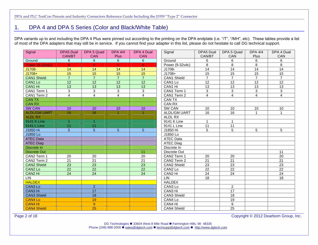
1. DPA 4 and DPA 5 Series (Color and Black/White Table)
DPA variants up to and including the DPA 4 Plus were pinned out according to the printing on the DPA endplate (i.e. “/T”, “/MH”, etc). These tables provide a list of most of the DPA adapters that may still be in service. If you cannot find your adapter in this list, please do not hesitate to call DG technical support.
Signal DPA5 Dual CAN/BT
DPA 5 Quad CAN
DPA 4/4 Plus
DPA 4 Dual CAN
Ground 6 6 6 6
Power (9-32vdc) 8 8 8 8
J1708- 14 14 14 14
J1708+ 15 15 15 15
CAN1 Shield 7 7 7 7
CAN1 Lo 12 12 12 12
CAN1 Hi 13 13 13 13
CAN1 Term 1 3 3 3 3
CAN1 Term 2 4 4 4 4
CAN TX
CAN RX
SW CAN 10 10 10 10
ALDL/GM UART 16 16 1 1
ALDL RX
9141 K Line 1 1
9141 L Line 11 11
J1850 Hi 5 5 5 5
J1850 Lo
ATEC Data
ATEC Diag
Discrete In
Discrete Out 11
CAN2 Term 1 20 20 20
CAN2 Term 2 21 21 21
CAN2 Shield 23 23 23
CAN2 Lo 22 22 22
CAN2 Hi 24 24 24
LIN
HALDEX
CAN3 Lo 2
CAN3 Hi 17
CAN3 Shield 18
CAN4 Lo 19
CAN4 Hi 9
CAN4 Shield 25
Signal DPA5 Dual CAN/BT
DPA 5 Quad CAN
DPA 4/4 Plus
DPA 4 Dual CAN
Ground 6 6 6 6
Power (9-32vdc) 8 8 8 8
J1708- 14 14 14 14
J1708+ 15 15 15 15
CAN1 Shield 7 7 7 7
CAN1 Lo 12 12 12 12
CAN1 Hi 13 13 13 13
CAN1 Term 1 3 3 3 3
CAN1 Term 2 4 4 4 4
CAN TX
CAN RX
SW CAN 10 10 10 10
ALDL/GM UART 16 16 1 1
ALDL RX
9141 K Line 1 1
9141 L Line 11 11
J1850 Hi 5 5 5 5
J1850 Lo
ATEC Data
ATEC Diag
Discrete In
Discrete Out 11
CAN2 Term 1 20 20 20
CAN2 Term 2 21 21 21
CAN2 Shield 23 23 23
CAN2 Lo 22 22 22
CAN2 Hi 24 24 24
LIN 18 18
HALDEX
CAN3 Lo 2
CAN3 Hi 17
CAN3 Shield 18
CAN4 Lo 19
CAN4 Hi 9
CAN4 Shield 25
DPA and PLC TestCon Pinouts and Industry Connectors Reference Guide Including the J1939 “Type 2” Connector
Page 3 of 18 Copyright © 2012 Dearborn Group, Inc.
DG Technologies 33604 West 8 Mile Road Farmington Hills, MI 48335 Phone (248) 888-2000 [email protected] [email protected] http://www.dgtech.com
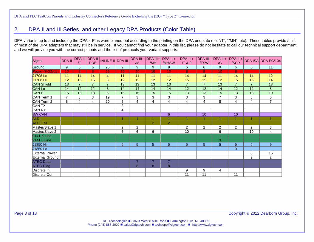
2. DPA II and III Series, and other Legacy DPA Products (Color Table)
DPA variants up to and including the DPA 4 Plus were pinned out according to the printing on the DPA endplate (i.e. “/T”, “/MH”, etc). These tables provide a list of most of the DPA adapters that may still be in service. If you cannot find your adapter in this list, please do not hesitate to call our technical support department and we will provide you with the correct pinouts and the list of protocols your variant supports.
Signal DPA II DPA II
/T DPA II DDE
INLINE II DPA III DPA III+
/M DPA III+
/MH DPA III+ /MHSW
DPA III+ /T & /I
DPA III+ /TSW
DPA III+ /C
DPA III+ /SCP
DPA ISA DPA PC/104
Ground 9 6 6 25 9 9 9 9 6 6 9 6 6 11
Power (9-32vdc) 10 8 8 23 10 10 10 10 8 8 10 8
J1708 Lo 11 14 14 4 11 11 11 11 14 14 11 14 14 12
J1708 Hi 12 15 15 3 12 12 12 12 15 15 12 15 15 14
CAN Shield 13 7 7 7 13 13 13 13 7 7 13 7 7 13
CAN Lo 14 12 12 8 14 14 14 14 12 12 14 12 12 8
CAN Hi 15 13 13 6 15 15 15 15 13 13 15 13 13 10
CAN Term 1 7 3 3 19 7 3 3 3 3 3 7 3 3 5
CAN Term 2 8 4 4 20 8 4 4 4 4 4 8 4 4 7
CAN TX 3
CAN RX 4
SW CAN 6 10 10
ALDL 1 1 1 1 1 1 1 1 1 1
ALDL RX 2 2
Master/Slave 1 2 2 2 2 2 2 2 3
Master/Slave 2 6 6 6 10 6 10 4
9141 K Line 1
9141 L Line 3
J1850 Hi 5 5 5 5 5 5 5 5 5 9
J1850 Lo 9
External Power 8 15
External Ground 9 2
ATEC Data 7 7 7
ATEC Diag 8 8 8
Discrete In 9 9 4
Discrete Out 11 11 11
DPA and PLC TestCon Pinouts and Industry Connectors Reference Guide Including the J1939 “Type 2” Connector
Page 4 of 18 Copyright © 2012 Dearborn Group, Inc.
DG Technologies 33604 West 8 Mile Road Farmington Hills, MI 48335 Phone (248) 888-2000 [email protected] [email protected] http://www.dgtech.com
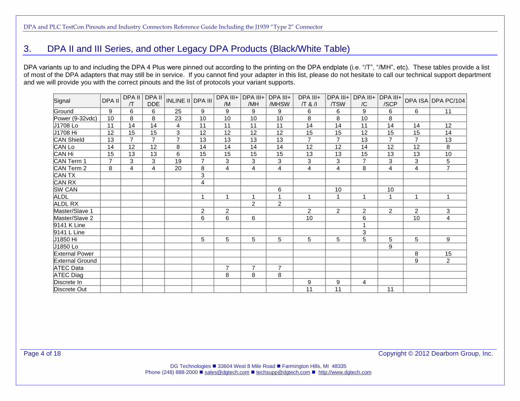
3. DPA II and III Series, and other Legacy DPA Products (Black/White Table)
DPA variants up to and including the DPA 4 Plus were pinned out according to the printing on the DPA endplate (i.e. “/T”, “/MH”, etc). These tables provide a list of most of the DPA adapters that may still be in service. If you cannot find your adapter in this list, please do not hesitate to call our technical support department and we will provide you with the correct pinouts and the list of protocols your variant supports.
Signal DPA II DPA II
/T DPA II DDE
INLINE II DPA III DPA III+
/M DPA III+
/MH DPA III+ /MHSW
DPA III+ /T & /I
DPA III+ /TSW
DPA III+ /C
DPA III+ /SCP
DPA ISA DPA PC/104
Ground 9 6 6 25 9 9 9 9 6 6 9 6 6 11
Power (9-32vdc) 10 8 8 23 10 10 10 10 8 8 10 8
J1708 Lo 11 14 14 4 11 11 11 11 14 14 11 14 14 12
J1708 Hi 12 15 15 3 12 12 12 12 15 15 12 15 15 14
CAN Shield 13 7 7 7 13 13 13 13 7 7 13 7 7 13
CAN Lo 14 12 12 8 14 14 14 14 12 12 14 12 12 8
CAN Hi 15 13 13 6 15 15 15 15 13 13 15 13 13 10
CAN Term 1 7 3 3 19 7 3 3 3 3 3 7 3 3 5
CAN Term 2 8 4 4 20 8 4 4 4 4 4 8 4 4 7
CAN TX 3
CAN RX 4
SW CAN 6 10 10
ALDL 1 1 1 1 1 1 1 1 1 1
ALDL RX 2 2
Master/Slave 1 2 2 2 2 2 2 2 3
Master/Slave 2 6 6 6 10 6 10 4
9141 K Line 1
9141 L Line 3
J1850 Hi 5 5 5 5 5 5 5 5 5 9
J1850 Lo 9
External Power 8 15
External Ground 9 2
ATEC Data 7 7 7
ATEC Diag 8 8 8
Discrete In 9 9 4
Discrete Out 11 11 11
DPA and PLC TestCon Pinouts and Industry Connectors Reference Guide Including the J1939 “Type 2” Connector
Page 5 of 18 Copyright © 2012 Dearborn Group, Inc.
DG Technologies 33604 West 8 Mile Road Farmington Hills, MI 48335 Phone (248) 888-2000 [email protected] [email protected] http://www.dgtech.com
4. Deutsch Connectors (3/6/9-Pin)
NOTE: On the Deutsch 9-pin SAE Standard Heavy-Duty Truck Connector, pins H and J are labeled “OEM Specific”. Some truck OEMs have used these pins differently (i.e. PACCAR and ISO9141), however the most common use of these pins is for a second CAN channel (i.e. Freightliner Cascadia). It has been requested of all diagnostic adapter vendors by the TMC RP1210 task force to use blue colored sheathing on their vehicle-side cables that are wired for a second CAN channel (as per the Freightliner Cascadia model). DG uses blue colored sheathing on our DPA 5 cables that support a second CAN channel.
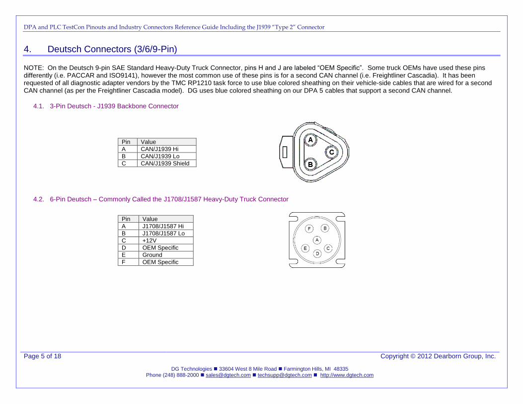
4.1. 3-Pin Deutsch - J1939 Backbone Connector
Pin Value
A CAN/J1939 Hi
B CAN/J1939 Lo
C CAN/J1939 Shield
4.2. 6-Pin Deutsch – Commonly Called the J1708/J1587 Heavy-Duty Truck Connector
Pin Value
A J1708/J1587 Hi
B J1708/J1587 Lo
C +12V
D OEM Specific
E Ground
F OEM Specific
DPA and PLC TestCon Pinouts and Industry Connectors Reference Guide Including the J1939 “Type 2” Connector
Page 6 of 18 Copyright © 2012 Dearborn Group, Inc.
DG Technologies 33604 West 8 Mile Road Farmington Hills, MI 48335 Phone (248) 888-2000 [email protected] [email protected] http://www.dgtech.com
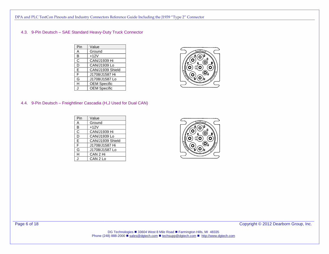
4.3. 9-Pin Deutsch – SAE Standard Heavy-Duty Truck Connector
Pin Value
A Ground
B +12V
C CAN/J1939 Hi
D CAN/J1939 Lo
E CAN/J1939 Shield
F J1708/J1587 Hi
G J1708/J1587 Lo
H OEM Specific
J OEM Specific
4.4. 9-Pin Deutsch – Freightliner Cascadia (H,J Used for Dual CAN)
Pin Value
A Ground
B +12V
C CAN/J1939 Hi
D CAN/J1939 Lo
E CAN/J1939 Shield
F J1708/J1587 Hi
G J1708/J1587 Lo
H CAN 2 Hi
J CAN 2 Lo
DPA and PLC TestCon Pinouts and Industry Connectors Reference Guide Including the J1939 “Type 2” Connector
Page 7 of 18 Copyright © 2012 Dearborn Group, Inc.
DG Technologies 33604 West 8 Mile Road Farmington Hills, MI 48335 Phone (248) 888-2000 [email protected] [email protected] http://www.dgtech.com
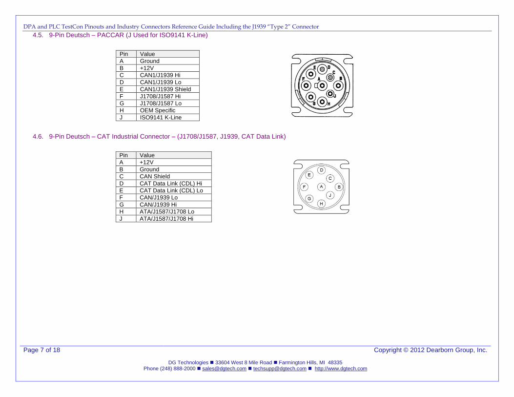
4.5. 9-Pin Deutsch – PACCAR (J Used for ISO9141 K-Line)
Pin Value
A Ground
B +12V
C CAN1/J1939 Hi
D CAN1/J1939 Lo
E CAN1/J1939 Shield
F J1708/J1587 Hi
G J1708/J1587 Lo
H OEM Specific
J ISO9141 K-Line
4.6. 9-Pin Deutsch – CAT Industrial Connector – (J1708/J1587, J1939, CAT Data Link)
Pin Value
A +12V
B Ground
C CAN Shield
D CAT Data Link (CDL) Hi
E CAT Data Link (CDL) Lo
F CAN/J1939 Lo
G CAN/J1939 Hi
H ATA/J1587/J1708 Lo
J ATA/J1587/J1708 Hi
DPA and PLC TestCon Pinouts and Industry Connectors Reference Guide Including the J1939 “Type 2” Connector
Page 8 of 18 Copyright © 2012 Dearborn Group, Inc.
DG Technologies 33604 West 8 Mile Road Farmington Hills, MI 48335 Phone (248) 888-2000 [email protected] [email protected] http://www.dgtech.com
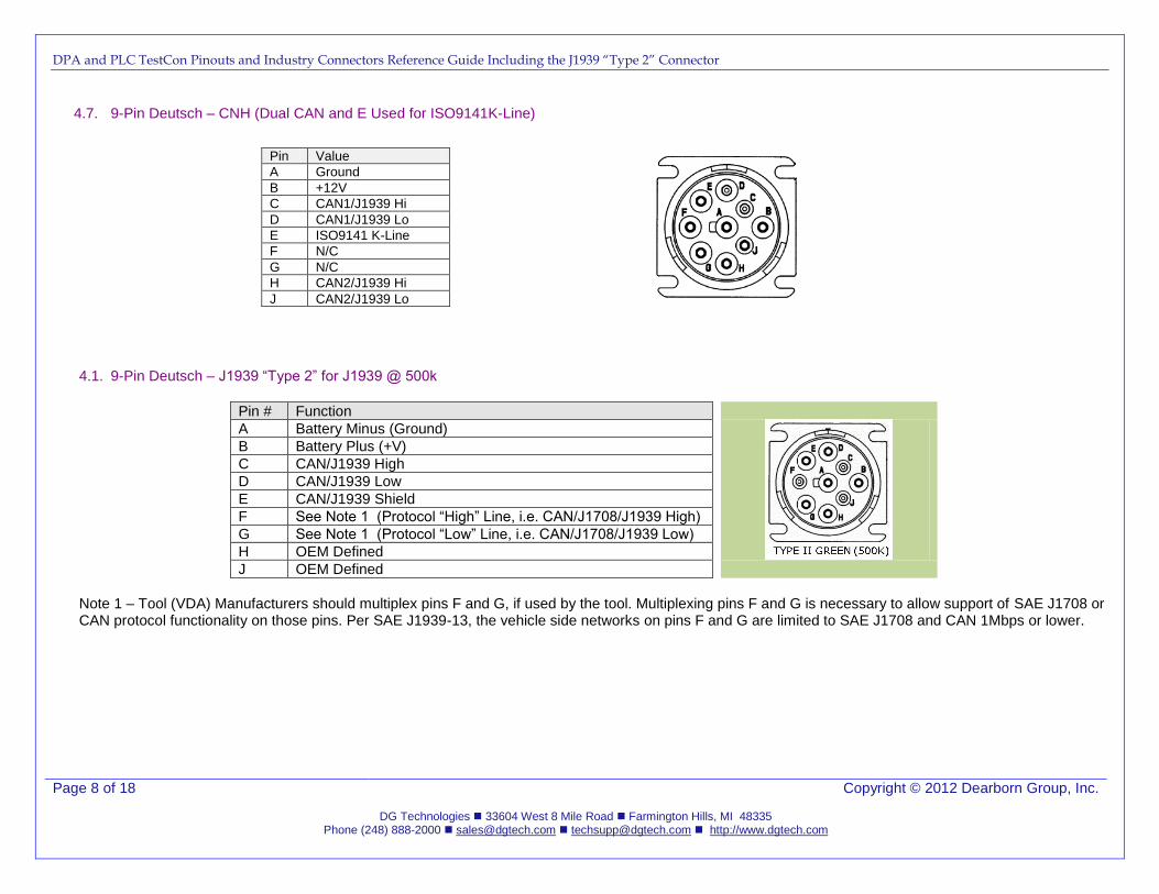
4.7. 9-Pin Deutsch – CNH (Dual CAN and E Used for ISO9141K-Line)
Pin Value
A Ground
B +12V
C CAN1/J1939 Hi
D CAN1/J1939 Lo
E ISO9141 K-Line
F N/C
G N/C
H CAN2/J1939 Hi
J CAN2/J1939 Lo
4.1. 9-Pin Deutsch – J1939 “Type 2” for J1939 @ 500k
Pin # Function
A Battery Minus (Ground)
B Battery Plus (+V)
C CAN/J1939 High
D CAN/J1939 Low
E CAN/J1939 Shield
F See Note 1 (Protocol “High” Line, i.e. CAN/J1708/J1939 High)
G See Note 1 (Protocol “Low” Line, i.e. CAN/J1708/J1939 Low)
H OEM Defined
J OEM Defined
Note 1 – Tool (VDA) Manufacturers should multiplex pins F and G, if used by the tool. Multiplexing pins F and G is necessary to allow support of SAE J1708 or CAN protocol functionality on those pins. Per SAE J1939-13, the vehicle side networks on pins F and G are limited to SAE J1708 and CAN 1Mbps or lower.
DPA and PLC TestCon Pinouts and Industry Connectors Reference Guide Including the J1939 “Type 2” Connector
Page 9 of 18 Copyright © 2012 Dearborn Group, Inc.
DG Technologies 33604 West 8 Mile Road Farmington Hills, MI 48335 Phone (248) 888-2000 [email protected] [email protected] http://www.dgtech.com
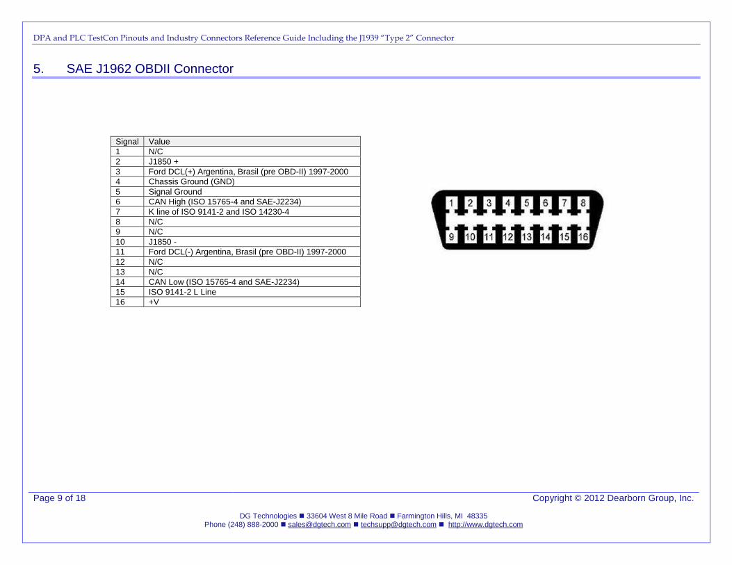
5. SAE J1962 OBDII Connector
Signal Value
1 N/C
2 J1850 +
3 Ford DCL(+) Argentina, Brasil (pre OBD-II) 1997-2000
4 Chassis Ground (GND)
5 Signal Ground
6 CAN High (ISO 15765-4 and SAE-J2234)
7 K line of ISO 9141-2 and ISO 14230-4
8 N/C
9 N/C
10 J1850 -
11 Ford DCL(-) Argentina, Brasil (pre OBD-II) 1997-2000
12 N/C
13 N/C
14 CAN Low (ISO 15765-4 and SAE-J2234)
15 ISO 9141-2 L Line
16 +V
DPA and PLC TestCon Pinouts and Industry Connectors Reference Guide Including the J1939 “Type 2” Connector
Page 10 of 18 Copyright © 2012 Dearborn Group, Inc.
DG Technologies 33604 West 8 Mile Road Farmington Hills, MI 48335 Phone (248) 888-2000 [email protected] [email protected] http://www.dgtech.com
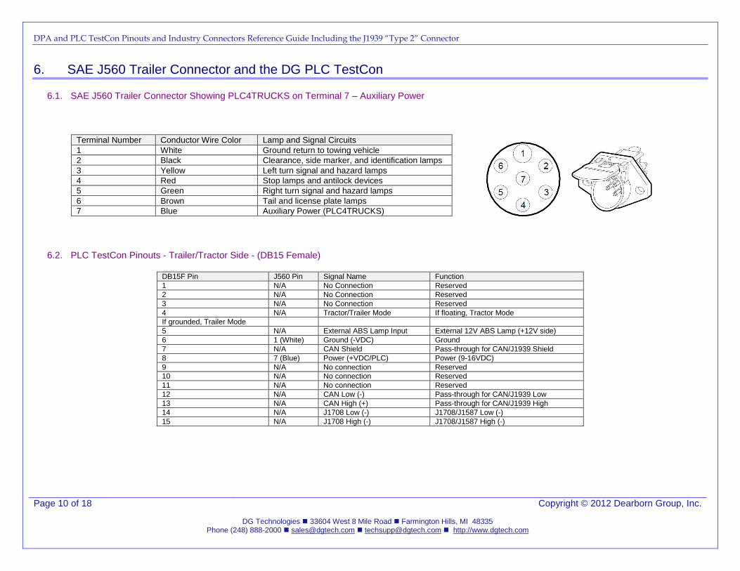
6. SAE J560 Trailer Connector and the DG PLC TestCon
6.1. SAE J560 Trailer Connector Showing PLC4TRUCKS on Terminal 7 – Auxiliary Power
Terminal Number Conductor Wire Color Lamp and Signal Circuits
1 White Ground return to towing vehicle
2 Black Clearance, side marker, and identification lamps
3 Yellow Left turn signal and hazard lamps
4 Red Stop lamps and antilock devices
5 Green Right turn signal and hazard lamps
6 Brown Tail and license plate lamps
7 Blue Auxiliary Power (PLC4TRUCKS)
6.2. PLC TestCon Pinouts - Trailer/Tractor Side - (DB15 Female)
DB15F Pin J560 Pin Signal Name Function
1 N/A No Connection Reserved
2 N/A No Connection Reserved
3 N/A No Connection Reserved
4 N/A Tractor/Trailer Mode If floating, Tractor Mode
If grounded, Trailer Mode
5 N/A External ABS Lamp Input External 12V ABS Lamp (+12V side)
6 1 (White) Ground (-VDC) Ground
7 N/A CAN Shield Pass-through for CAN/J1939 Shield
8 7 (Blue) Power (+VDC/PLC) Power (9-16VDC)
9 N/A No connection Reserved
10 N/A No connection Reserved
11 N/A No connection Reserved
12 N/A CAN Low (-) Pass-through for CAN/J1939 Low
13 N/A CAN High (+) Pass-through for CAN/J1939 High
14 N/A J1708 Low (-) J1708/J1587 Low (-)
15 N/A J1708 High (-) J1708/J1587 High (-)
DPA and PLC TestCon Pinouts and Industry Connectors Reference Guide Including the J1939 “Type 2” Connector
Page 11 of 18 Copyright © 2012 Dearborn Group, Inc.
DG Technologies 33604 West 8 Mile Road Farmington Hills, MI 48335 Phone (248) 888-2000 [email protected] [email protected] http://www.dgtech.com
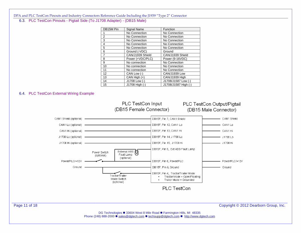
6.3. PLC TestCon Pinouts - Pigtail Side (To J1708 Adapter) - (DB15 Male)
DB15M Pin Signal Name Function
1 No Connection No Connection
2 No Connection No Connection
3 No Connection No Connection
4 No Connection No Connection
5 No Connection No Connection
6 Ground (-VDC) Ground
7 CAN/J1939 Shield CAN/J1939 Shield
8 Power (+VDC/PLC) Power (9-16VDC)
9 No connection No Connection
10 No connection No Connection
11 No connection No Connection
12 CAN Low (-) CAN/J1939 Low
13 CAN High (+) CAN/J1939 High
14 J1708 Low (-) J1708/J1587 Low (-)
15 J1708 High (-) J1708/J1587 High (-)
6.4. PLC TestCon External Wiring Example
DPA and PLC TestCon Pinouts and Industry Connectors Reference Guide Including the J1939 “Type 2” Connector
Page 12 of 18 Copyright © 2012 Dearborn Group, Inc.
DG Technologies 33604 West 8 Mile Road Farmington Hills, MI 48335 Phone (248) 888-2000 [email protected] [email protected] http://www.dgtech.com
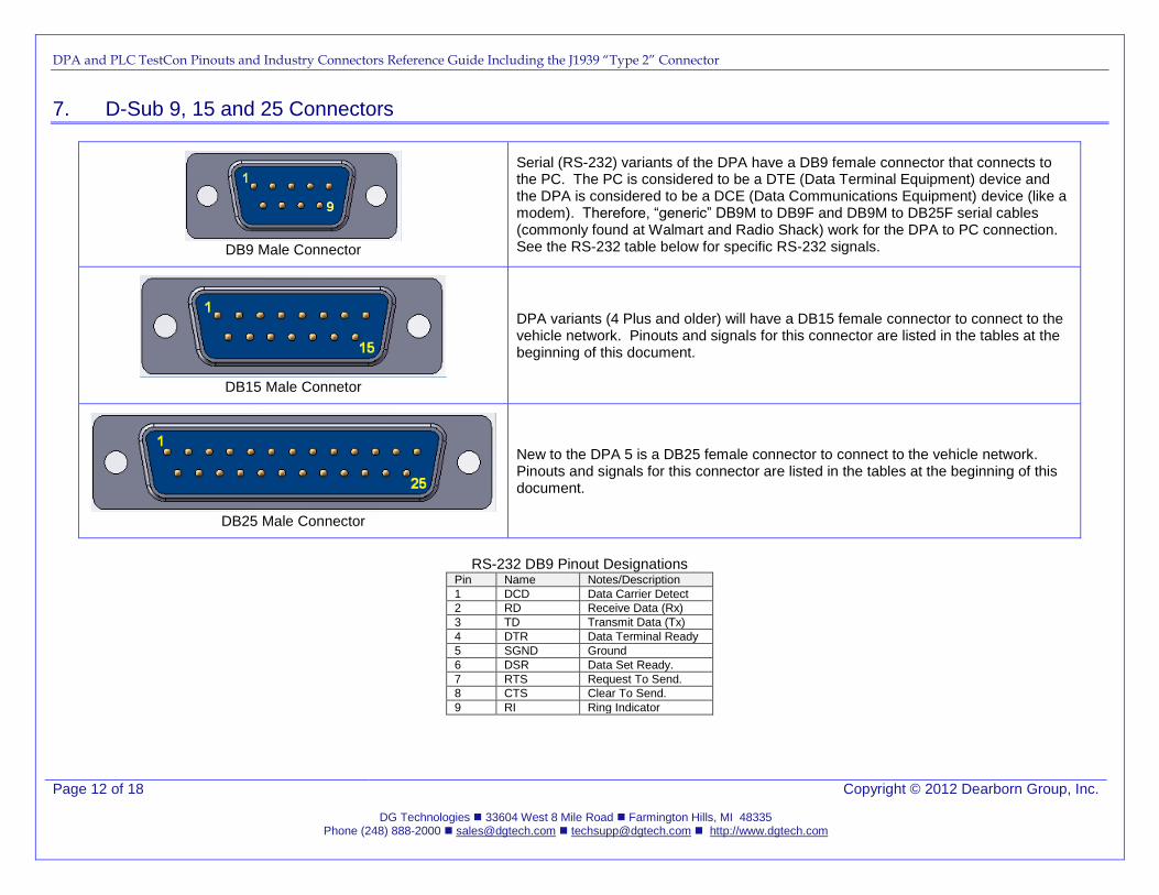
7. D-Sub 9, 15 and 25 Connectors
DB9 Male Connector
Serial (RS-232) variants of the DPA have a DB9 female connector that connects to the PC. The PC is considered to be a DTE (Data Terminal Equipment) device and the DPA is considered to be a DCE (Data Communications Equipment) device (like a modem). Therefore, “generic” DB9M to DB9F and DB9M to DB25F serial cables (commonly found at Walmart and Radio Shack) work for the DPA to PC connection. See the RS-232 table below for specific RS-232 signals.
DB15 Male Connetor
DPA variants (4 Plus and older) will have a DB15 female connector to connect to the vehicle network. Pinouts and signals for this connector are listed in the tables at the beginning of this document.
DB25 Male Connector
New to the DPA 5 is a DB25 female connector to connect to the vehicle network. Pinouts and signals for this connector are listed in the tables at the beginning of this document.
RS-232 DB9 Pinout Designations
Pin Name Notes/Description
1 DCD Data Carrier Detect
2 RD Receive Data (Rx)
3 TD Transmit Data (Tx)
4 DTR Data Terminal Ready
5 SGND Ground
6 DSR Data Set Ready.
7 RTS Request To Send.
8 CTS Clear To Send.
9 RI Ring Indicator
DPA and PLC TestCon Pinouts and Industry Connectors Reference Guide Including the J1939 “Type 2” Connector
Page 13 of 18 Copyright © 2012 Dearborn Group, Inc.
DG Technologies 33604 West 8 Mile Road Farmington Hills, MI 48335 Phone (248) 888-2000 [email protected] [email protected] http://www.dgtech.com
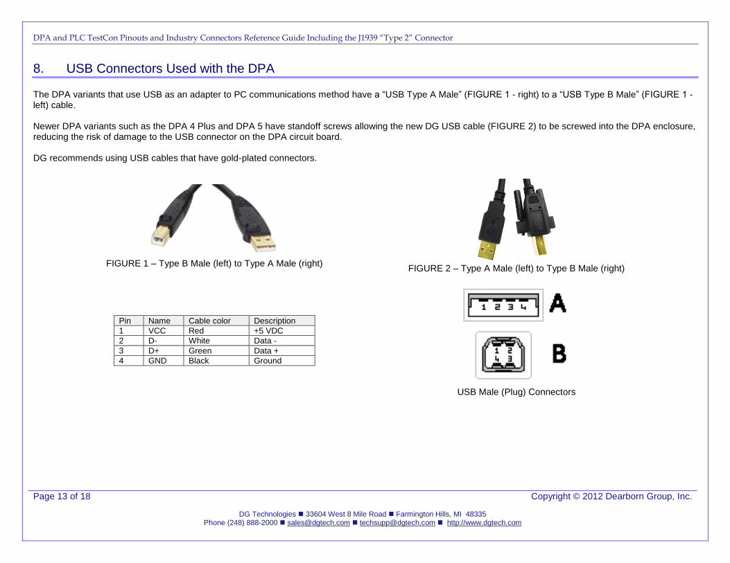
8. USB Connectors Used with the DPA
The DPA variants that use USB as an adapter to PC communications method have a “USB Type A Male” (FIGURE 1 - right) to a “USB Type B Male” (FIGURE 1 - left) cable. Newer DPA variants such as the DPA 4 Plus and DPA 5 have standoff screws allowing the new DG USB cable (FIGURE 2) to be screwed into the DPA enclosure, reducing the risk of damage to the USB connector on the DPA circuit board. DG recommends using USB cables that have gold-plated connectors.
FIGURE 1 – Type B Male (left) to Type A Male (right)
FIGURE 2 – Type A Male (left) to Type B Male (right)
Pin Name Cable color Description
1 VCC Red +5 VDC
2 D- White Data -
3 D+ Green Data +
4 GND Black Ground
USB Male (Plug) Connectors
DPA and PLC TestCon Pinouts and Industry Connectors Reference Guide Including the J1939 “Type 2” Connector
Page 14 of 18 Copyright © 2012 Dearborn Group, Inc.
DG Technologies 33604 West 8 Mile Road Farmington Hills, MI 48335 Phone (248) 888-2000 [email protected] [email protected] http://www.dgtech.com
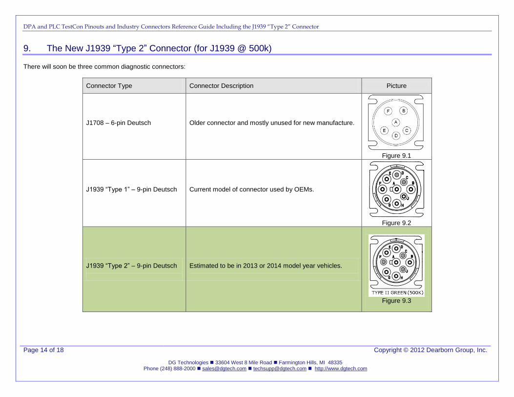
9. The New J1939 “Type 2” Connector (for J1939 @ 500k)
There will soon be three common diagnostic connectors:
Connector Type Connector Description Picture
J1708 – 6-pin Deutsch
Older connector and mostly unused for new manufacture.
Figure 9.1
J1939 “Type 1” – 9-pin Deutsch
Current model of connector used by OEMs.
Figure 9.2
J1939 “Type 2” – 9-pin Deutsch
Estimated to be in 2013 or 2014 model year vehicles.
Figure 9.3
DPA and PLC TestCon Pinouts and Industry Connectors Reference Guide Including the J1939 “Type 2” Connector
Page 15 of 18 Copyright © 2012 Dearborn Group, Inc.
DG Technologies 33604 West 8 Mile Road Farmington Hills, MI 48335 Phone (248) 888-2000 [email protected] [email protected] http://www.dgtech.com
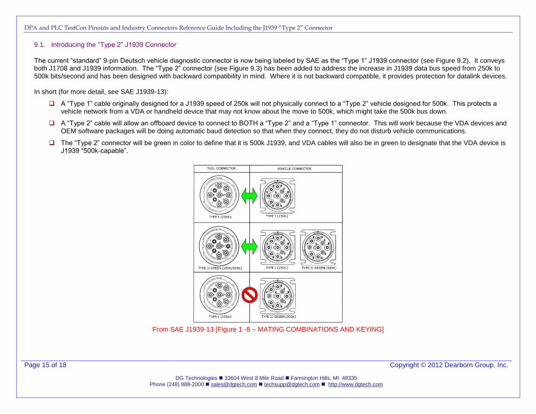
9.1. Introducing the “Type 2” J1939 Connector
The current “standard” 9-pin Deutsch vehicle diagnostic connector is now being labeled by SAE as the “Type 1” J1939 connector (see Figure 9.2). It conveys both J1708 and J1939 information. The “Type 2” connector (see Figure 9.3) has been added to address the increase in J1939 data bus speed from 250k to 500k bits/second and has been designed with backward compatibility in mind. Where it is not backward compatible, it provides protection for datalink devices.
In short (for more detail, see SAE J1939-13):
A “Type 1” cable originally designed for a J1939 speed of 250k will not physically connect to a “Type 2” vehicle designed for 500k. This protects a vehicle network from a VDA or handheld device that may not know about the move to 500k, which might take the 500k bus down.
A “Type 2” cable will allow an offboard device to connect to BOTH a “Type 2” and a “Type 1” connector. This will work because the VDA devices and OEM software packages will be doing automatic baud detection so that when they connect, they do not disturb vehicle communications.
The “Type 2” connector will be green in color to define that it is 500k J1939, and VDA cables will also be in green to designate that the VDA device is J1939 “500k-capable”.
From SAE J1939-13 [Figure 1 -8 – MATING COMBINATIONS AND KEYING]
DPA and PLC TestCon Pinouts and Industry Connectors Reference Guide Including the J1939 “Type 2” Connector
Page 16 of 18 Copyright © 2012 Dearborn Group, Inc.
DG Technologies 33604 West 8 Mile Road Farmington Hills, MI 48335 Phone (248) 888-2000 [email protected] [email protected] http://www.dgtech.com
10. Appendix A. SAE J1708 Connector and Part Numbers
HD10-6-12P
J1708 Cab Mounted Receptacle
HD16-6-12S
J1708 Mating Plug
10.1. SAE J1708 In-Cab Connector Part Number
Receptacle HD10-6-12P
Pin Contact 0460-220-1231
Sealing Cap HDC16-6
10.2. SAE J1708 Mating Plug Part Number
Plug HD16-6-12S
Sockets 0462-210-1231
Strain Relief HD18-006
DPA and PLC TestCon Pinouts and Industry Connectors Reference Guide Including the J1939 “Type 2” Connector
Page 17 of 18 Copyright © 2012 Dearborn Group, Inc.
DG Technologies 33604 West 8 Mile Road Farmington Hills, MI 48335 Phone (248) 888-2000 [email protected] [email protected] http://www.dgtech.com
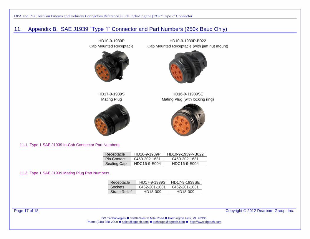
11. Appendix B. SAE J1939 “Type 1” Connector and Part Numbers (250k Baud Only)
HD10-9-1939P
Cab Mounted Receptacle
HD10-9-1939P-B022
Cab Mounted Receptacle (with jam nut mount)
HD17-9-1939S
Mating Plug
HD16-9-J1939SE
Mating Plug (with locking ring)
11.1. Type 1 SAE J1939 In-Cab Connector Part Numbers
Receptacle HD10-9-1939P HD10-9-1939P-B022
Pin Contact 0460-202-1631 0460-202-1631
Sealing Cap HDC16-9-E004 HDC16-9-E004
11.2. Type 1 SAE J1939 Mating Plug Part Numbers
Receptacle HD17-9-1939S HD17-9-1939SE
Sockets 0462-201-1631 0462-201-1631
Strain Relief HD18-009 HD18-009
DPA and PLC TestCon Pinouts and Industry Connectors Reference Guide Including the J1939 “Type 2” Connector
Page 18 of 18 Copyright © 2012 Dearborn Group, Inc.
DG Technologies 33604 West 8 Mile Road Farmington Hills, MI 48335 Phone (248) 888-2000 [email protected] [email protected] http://www.dgtech.com
12. Appendix C. SAE J1939 “Type 2” Connector (J1939 @ 500k Capable)
12.1. Type 2 SAE J1939 Connector Pictures
Cab Mounted Receptacle
HD10-9-1939P-P080
Cab Mounted Receptacle (with jam nut mount)
HD10-9-1939P-BP03
PICTURE TBD PICTURE TBD
Mating Plug
HD17-9-1939S-P080
Mating Plug (with locking ring)
HD16-9-1939S-P080
PICTURE TBD PICTURE TBD
12.2. Type 2 SAE J1939 In-Cab Connector Part Numbers
Receptacle HD10-9-1939P HD10-9-1939P-B022
Pin Contact 0460-202-1631 0460-202-1631
Sealing Cap HDC16-9-E004 HDC16-9-E004
12.3. Type 2 SAE J1939 Mating Plug Part Numbers
Receptacle HD17-9-1939S HD17-9-1939SE
Sockets 0462-201-1631 0462-201-1631
Strain Relief HD18-009 HD18-009
Related Documents