Elmaset www.elma.com C | 1_1 C 1: Front Panels for Sub Racks and Enclosures 1.1 Flat Front Panels C | 1_2 1.1.1 Front Panel Screws C | 1_2 1.2 EMC Flat Front Panels C | 1_3 1.2.1 EMC Filler Panel with EMC Gasket C | 1_4 1.2.2 EMC Filler Panel without EMC Gasket C | 1_4 1.2.3 EMC Flat Front Panels C | 1_5 1.2.4 Superior EMC Level C | 1_6 1.2.5 Perforated EMC Front Panel 84 HP C | 1_6 1.3 Fan Front Panels C | 1_7 1.3.1 Fan Front Panel 84 HP for Vertical Ventilation C | 1_7 1.3.2 Fan Front Panel for Horizontal Ventilation C | 1_8 1.3.3 Fan Front Panels for Direct Fan Mounting C | 1_8 1.4 Hinged Front Panels C | 1_9 1.4.1 Top / Bottom-Hinged Front Panel C | 1_9 1.4.2 EMC Top / Bottom-Hinged Front Panel C | 1_10 1.4.3 Side-Hinged Front Panel C | 1_10 1.4.4 Accessories C | 1_11

Welcome message from author
This document is posted to help you gain knowledge. Please leave a comment to let me know what you think about it! Share it to your friends and learn new things together.
Transcript
Elmasetwww.elma.com C | 1_1
C1: Front Panels for Sub Racks and Enclosures
1.1 Flat Front Panels C | 1_2
1.1.1 Front Panel Screws C | 1_2
1.2 EMC Flat Front Panels C | 1_3
1.2.1 EMC Filler Panel with EMC Gasket C | 1_4
1.2.2 EMC Filler Panel without EMC Gasket C | 1_4
1.2.3 EMC Flat Front Panels C | 1_5
1.2.4 Superior EMC Level C | 1_6
1.2.5 Perforated EMC Front Panel 84 HP C | 1_6
1.3 Fan Front Panels C | 1_7
1.3.1 Fan Front Panel 84 HP for Vertical Ventilation C | 1_7
1.3.2 Fan Front Panel for Horizontal Ventilation C | 1_8
1.3.3 Fan Front Panels for Direct Fan Mounting C | 1_8
1.4 Hinged Front Panels C | 1_9
1.4.1 Top / Bottom-Hinged Front Panel C | 1_9
1.4.2 EMC Top / Bottom-Hinged Front Panel C | 1_10
1.4.3 Side-Hinged Front Panel C | 1_10
1.4.4 Accessories C | 1_11
www.elma.comElmasetC | 1_2
C1: Front Panels for Sub Racks and Enclosures
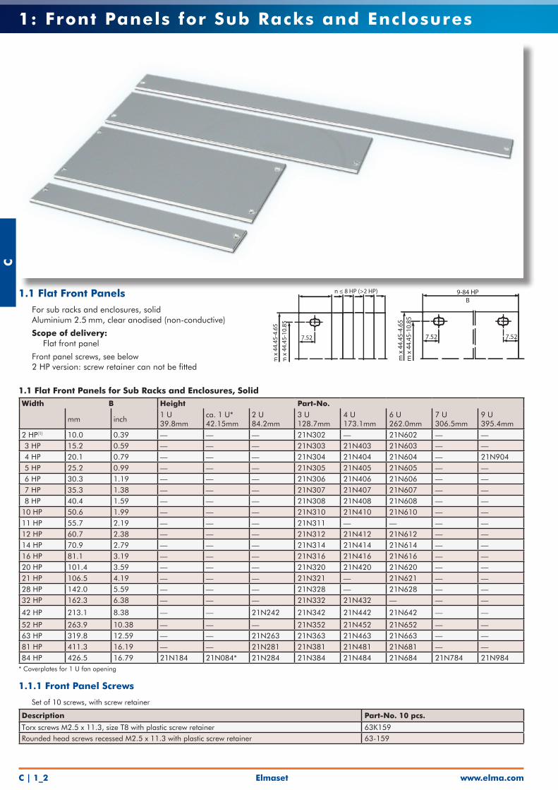
1.1 Flat Front Panels for Sub Racks and Enclosures, SolidWidth B Height Part-No.
mm inch1 U39.8mm
ca. 1 U*42.15mm
2 U84.2mm
3 U128.7mm
4 U173.1mm
6 U262.0mm
7 U306.5mm
9 U395.4mm
2 HP(1) 10.0 0.39 — — — 21N302 — 21N602 — — 3 HP 15.2 0.59 — — — 21N303 21N403 21N603 — — 4 HP 20.1 0.79 — — — 21N304 21N404 21N604 — 21N904 5 HP 25.2 0.99 — — — 21N305 21N405 21N605 — — 6 HP 30.3 1.19 — — — 21N306 21N406 21N606 — — 7 HP 35.3 1.38 — — — 21N307 21N407 21N607 — — 8 HP 40.4 1.59 — — — 21N308 21N408 21N608 — — 10 HP 50.6 1.99 — — — 21N310 21N410 21N610 — — 11 HP 55.7 2.19 — — — 21N311 — — — — 12 HP 60.7 2.38 — — — 21N312 21N412 21N612 — — 14 HP 70.9 2.79 — — — 21N314 21N414 21N614 — — 16 HP 81.1 3.19 — — — 21N316 21N416 21N616 — — 20 HP 101.4 3.59 — — — 21N320 21N420 21N620 — — 21 HP 106.5 4.19 — — — 21N321 — 21N621 — — 28 HP 142.0 5.59 — — — 21N328 — 21N628 — — 32 HP 162.3 6.38 — — — 21N332 21N432 — — —
42 HP 213.1 8.38 — — 21N242 21N342 21N442 21N642 — —
52 HP 263.9 10.38 — — — 21N352 21N452 21N652 — —63 HP 319.8 12.59 — — 21N263 21N363 21N463 21N663 — —81 HP 411.3 16.19 — — 21N281 21N381 21N481 21N681 — —84 HP 426.5 16.79 21N184 21N084* 21N284 21N384 21N484 21N684 21N784 21N984
* Coverplates for 1 U fan opening
1.1.1 Front Panel Screws
• Set of 10 screws, with screw retainer
Description Part-No. 10 pcs.
Torx screws M2.5 x 11.3, size T8 with plastic screw retainer 63K159Rounded head screws recessed M2.5 x 11.3 with plastic screw retainer 63-159
m x
44.
45-4
.65
m x
44.
45-1
0.85
7.52 7.52
9-84 HPB
m x
44.
45-4
.65
m x
44.
45-1
0.85
7.52
n ≤ 8 HP (>2 HP)1.1 Flat Front Panels
• For sub racks and enclosures, solid• Aluminium 2.5 mm, clear anodised (non-conductive)
• Scope of delivery: • Flat front panel
• Front panel screws, see below• 2 HP version: screw retainer can not be fitted
Elmasetwww.elma.com C | 1_3
C1: Front Panels for Sub Racks and Enclosures
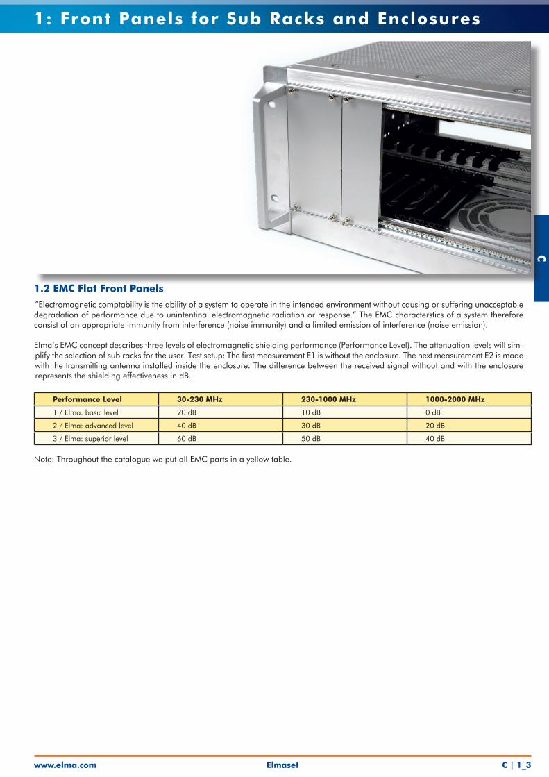
1.2 EMC Flat Front Panels
“Electromagnetic comptability is the ability of a system to operate in the intended environment without causing or suffering unacceptable degradation of performance due to unintentinal electromagnetic radiation or response.” The EMC characterstics of a system therefore consist of an appropriate immunity from interference (noise immunity) and a limited emission of interference (noise emission).
Elma’s EMC concept describes three levels of electromagnetic shielding performance (Performance Level). The attenuation levels will sim-plify the selection of sub racks for the user. Test setup: The first measurement E1 is without the enclosure. The next measurement E2 is made with the transmitting antenna installed inside the enclosure. The difference between the received signal without and with the enclosure represents the shielding effectiveness in dB.
Performance Level 30-230 MHz 230-1000 MHz 1000-2000 MHz
1 / Elma: basic level 20 dB 10 dB 0 dB
2 / Elma: advanced level 40 dB 30 dB 20 dB
3 / Elma: superior level 60 dB 50 dB 40 dB
Note: Throughout the catalogue we put all EMC parts in a yellow table.
www.elma.comElmasetC | 1_4
C1: Front Panels for Sub Racks and Enclosures
1.2.2 EMC Filler Panel without Gasket Width Part-No.
3 UPart-No. 4 U
Part-No. 6 U
4 HP 21B304 - - 10 HP 21B310 - - 12 HP 21B312 - - 16 HP 21B316 21B416 - 21 HP 21B321 21B421 - 42 HP 21B342 21B442 21B642 63 HP 21B363 21B463 - 84 HP 21B384 21B484 21B684
1.2.2.1 Front Panel Screws• Front panel width up to 9 HP = 2 screws; ≥ 10 HP = 4 screws
Description Part-No. Torx screw, M2.5 x 11.3, size T8 5443-08Rounded head screw, cross recessed M2.5 x 12.7 61-287
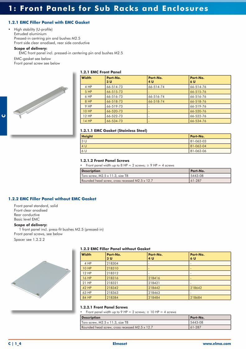
1.2.2 EMC Filler Panel without EMC Gasket
• Front panel standard, solid• Front clear anodised• Rear conductive• Basic level EMC
• Scope of delivery: • 1 front panel incl. press-fit bushes M2.5 (pressed-in)• Front panel screws, see below
• Spacer see 1.2.2.2
1.2.1 EMC Front Panel Width Part-No.
3 U Part-No. 4 U
Part-No. 6 U
4 HP 66-514-73 66-514-74 66-514-76 5 HP 66-515-73 - 66-515-76 6 HP 66-516-73 66-516-74 66-516-76 8 HP 66-518-73 66-518-74 66-518-76 9 HP 66-519-73 - 66-519-76 10 HP 66-520-73 - 66-520-76 12 HP 66-522-73 - 66-522-76 14 HP 66-534-73 - 66-534-76
1.2.1.1 EMC Gasket (Stainless Steel)Height Part-No. 3 U 81-062-034 U 81-062-046 U 81-062-06
1.2.1.2 Front Panel Screws• Front panel width up to 8 HP = 2 screws; ≥ 9 HP = 4 screws
Description Part-No. Torx screw, M2.5 x 11.3, size T8 5443-08Rounded head screw, cross recessed M2.5 x 12.7 61-287
1.2.1 EMC Filler Panel with EMC Gasket
• High stability (U-profile)• Extruded aluminium• Pressed-in centring pin and bushes M2.5• Front side clear anodised, rear side conductive
• Scope of delivery: • EMC front panel incl. pressed-in centering pin and bushes M2.5
• EMC-gasket see below• Front panel screw see below
Elmasetwww.elma.com C | 1_5
C1: Front Panels for Sub Racks and Enclosures
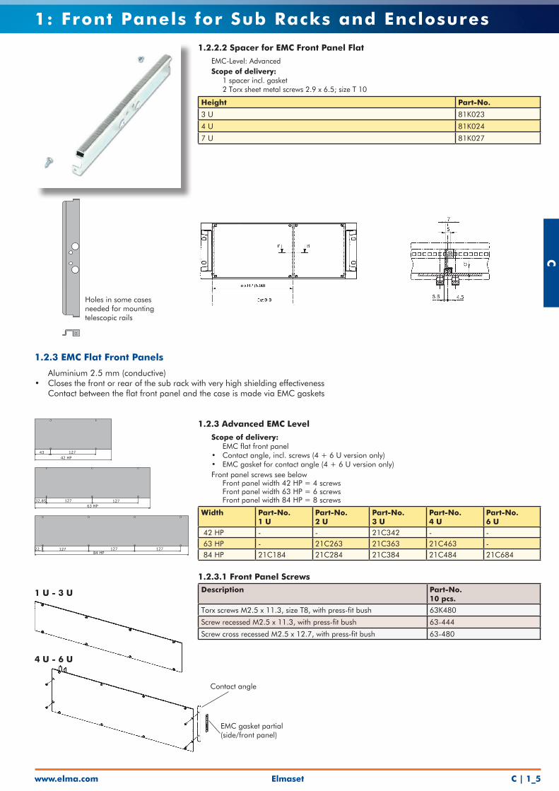
1.2.3 Advanced EMC Level
• Scope of delivery: • EMC flat front panel • Contact angle, incl. screws (4 + 6 U version only) • EMC gasket for contact angle (4 + 6 U version only)• Front panel screws see below • Front panel width 42 HP = 4 screws • Front panel width 63 HP = 6 screws • Front panel width 84 HP = 8 screws
Width Part-No. 1 U
Part-No. 2 U
Part-No. 3 U
Part-No. 4 U
Part-No. 6 U
42 HP - - 21C342 - - 63 HP - 21C263 21C363 21C463 - 84 HP 21C184 21C284 21C384 21C484 21C684
1.2.3.1 Front Panel ScrewsDescription Part-No.
10 pcs.
Torx screws M2.5 x 11.3, size T8, with press-fit bush 63K480
Screw recessed M2.5 x 11.3, with press-fit bush 63-444
Screw cross recessed M2.5 x 12.7, with press-fit bush 63-480
1.2.3 EMC Flat Front Panels
• Aluminium 2.5 mm (conductive)• Closes the front or rear of the sub rack with very high shielding effectiveness• Contact between the flat front panel and the case is made via EMC gaskets
1 U - 3 U
4 U - 6 U
Contact angle
EMC gasket partial (side/front panel)
84 HP
63 HP
42 HP
22,7 127127127
32,85 127127
43 127
1.2.2.2 Spacer for EMC Front Panel Flat
• EMC-Level: Advanced• Scope of delivery: • 1 spacer incl. gasket • 2 Torx sheet metal screws 2.9 x 6.5; size T 10
Height Part-No.
3 U 81K023
4 U 81K024
7 U 81K027
Holes in some cases needed for mounting telescopic rails
www.elma.comElmasetC | 1_6
C1: Front Panels for Sub Racks and Enclosures
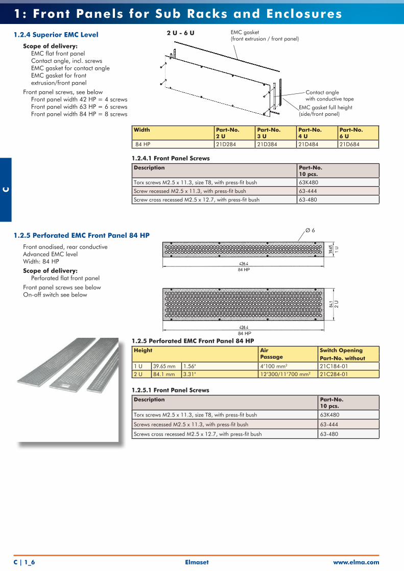
1.2.5 Perforated EMC Front Panel 84 HP
• Front anodised, rear conductive• Advanced EMC level• Width: 84 HP
• Scope of delivery: • Perforated flat front panel
• Front panel screws see below• On-off switch see below
Ø 6
Width Part-No. 2 U
Part-No. 3 U
Part-No. 4 U
Part-No. 6 U
84 HP 21D284 21D384 21D484 21D684
1.2.4.1 Front Panel ScrewsDescription Part-No.
10 pcs.
Torx screws M2.5 x 11.3, size T8, with press-fit bush 63K480
Screw recessed M2.5 x 11.3, with press-fit bush 63-444
Screw cross recessed M2.5 x 12.7, with press-fit bush 63-480
2 U - 6 U
EMC gasket full height (side/front panel)
Contact anglewith conductive tape
1.2.4 Superior EMC Level
• Scope of delivery: • EMC flat front panel • Contact angle, incl. screws • EMC gasket for contact angle • EMC gasket for front extrusion/front panel
• Front panel screws, see below • Front panel width 42 HP = 4 screws • Front panel width 63 HP = 6 screws • Front panel width 84 HP = 8 screws
EMC gasket(front extrusion / front panel)
1.2.5 Perforated EMC Front Panel 84 HPHeight Air
PassageSwitch OpeningPart-No. without
1 U 39.65 mm 1.56" 4’100 mm2 21C184-012 U 84.1 mm 3.31" 12’300/11’700 mm2 21C284-01
1.2.5.1 Front Panel ScrewsDescription Part-No.
10 pcs.
Torx screws M2.5 x 11.3, size T8, with press-fit bush 63K480
Screws recessed M2.5 x 11.3, with press-fit bush 63-444
Screws cross recessed M2.5 x 12.7, with press-fit bush 63-480
Elmasetwww.elma.com C | 1_7
C1: Front Panels for Sub Racks and Enclosures
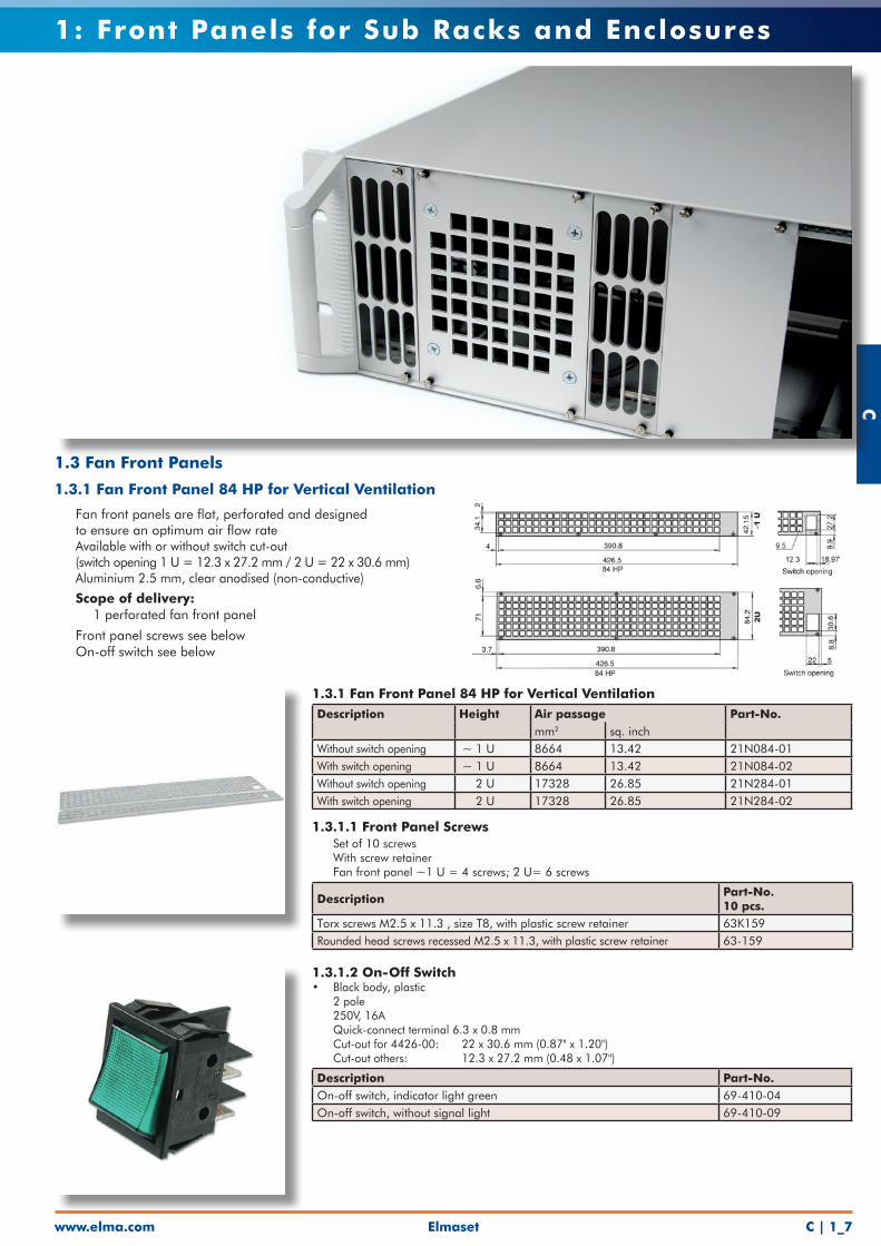
1.3.1 Fan Front Panel 84 HP for Vertical VentilationDescription Height Air passage Part-No.
mm2 sq. inchWithout switch opening ~ 1 U 8664 13.42 21N084-01With switch opening ~ 1 U 8664 13.42 21N084-02Without switch opening 2 U 17328 26.85 21N284-01With switch opening 2 U 17328 26.85 21N284-02
1.3.1.1 Front Panel Screws• Set of 10 screws• With screw retainer• Fan front panel ~1 U = 4 screws; 2 U= 6 screws
Description Part-No. 10 pcs.
Torx screws M2.5 x 11.3 , size T8, with plastic screw retainer 63K159Rounded head screws recessed M2.5 x 11.3, with plastic screw retainer 63-159
1.3.1.2 On-Off Switch• Black body, plastic• 2 pole• 250V, 16A• Quick-connect terminal 6.3 x 0.8 mm• Cut-out for 4426-00: 22 x 30.6 mm (0.87" x 1.20") Cut-out others: 12.3 x 27.2 mm (0.48 x 1.07")
Description Part-No.On-off switch, indicator light green 69-410-04On-off switch, without signal light 69-410-09
1.3 Fan Front Panels
1.3.1 Fan Front Panel 84 HP for Vertical Ventilation
• Fan front panels are flat, perforated and designed to ensure an optimum air flow rate• Available with or without switch cut-out (switch opening 1 U = 12.3 x 27.2 mm / 2 U = 22 x 30.6 mm)• Aluminium 2.5 mm, clear anodised (non-conductive)
• Scope of delivery: • 1 perforated fan front panel
• Front panel screws see below• On-off switch see below
www.elma.comElmasetC | 1_8
C1: Front Panels for Sub Racks and Enclosures
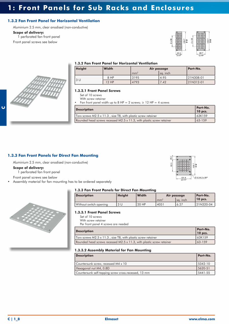
1.3.2 Fan Front Panel for Horizontal VentilationHeight Width Air passage Part-No.
mm2 sq. inch
3 U 8 HP 3195 4.95 21N308-01 12 HP 4793 7.42 21N312-01
1.3.2.1 Front Panel Screws• Set of 10 screws• With screw retainer• Fan front panel width up to 8 HP = 2 screws; ≥ 12 HP = 4 screws
DescriptionPart-No. 10 pcs.
Torx screws M2.5 x 11.3 , size T8, with plastic screw retainer 63K159Rounded head screws recessed M2.5 x 11.3, with plastic screw retainer 63-159
1.3.2 Fan Front Panel for Horizontal Ventilation
• Aluminium 2.5 mm, clear anodised (non-conductive)
• Scope of delivery: • 1 perforated fan front panel
• Front panel screws see below
1.3.3 Fan Front Panels for Direct Fan MountingDescription Height Width Air passage Part-No.
10 pcs.mm2 sq. inchWithout switch opening 3 U 20 HP 4051 6.27 21N320-04
1.3.3.1 Front Panel Screws• Set of 10 screws• With screw retainer• Per front panel 4 screws are needed
Description Part-No. 10 pcs.
Torx screws M2.5 x 11.3 , size T8, with plastic screw retainer 63K159Rounded head screws recessed M2.5 x 11.3, with plastic screw retainer 63-159
1.3.3.2 Assembly Material for Fan MountingDescription Part-No.
Countersunk screw, recessed M4 x 10 5342-10Hexagonal nut M4, 0.8D 5620-51Countersunk self-tapping screw cross.recessed, 13 mm 5441-55
1.3.3 Fan Front Panels for Direct Fan Mounting
• Aluminium 2.5 mm, clear anodised (non-conductive)
• Scope of delivery: • 1 perforated fan front panel
• Front panel screws see below• Assembly material for fan mounting has to be ordered separately
Elmasetwww.elma.com C | 1_9
C1: Front Panels for Sub Racks and Enclosures
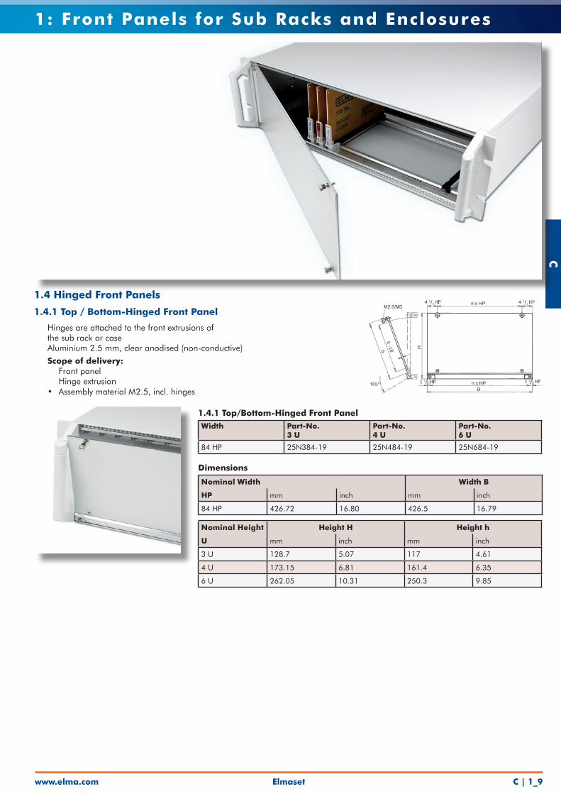
1.4.1 Top/Bottom-Hinged Front PanelWidth Part-No.
3 UPart-No. 4 U
Part-No. 6 U
84 HP 25N384-19 25N484-19 25N684-19
Dimensions
Nominal Width Width B
HP mm inch mm inch
84 HP 426.72 16.80 426.5 16.79
Nominal Height Height H Height h
U mm inch mm inch
3 U 128.7 5.07 117 4.61
4 U 173.15 6.81 161.4 6.35
6 U 262.05 10.31 250.3 9.85
1.4 Hinged Front Panels
1.4.1 Top / Bottom-Hinged Front Panel
• Hinges are attached to the front extrusions of the sub rack or case• Aluminium 2.5 mm, clear anodised (non-conductive)
• Scope of delivery: • Front panel • Hinge extrusion • Assembly material M2.5, incl. hinges
www.elma.comElmasetC | 1_10
C1: Front Panels for Sub Racks and Enclosures
Use Elma’s front panel service for machining and screen printing of your panels!
1.4.2 EMC Top / Bottom-Hinged Front PanelEMC Level Part-No.
3 UPart-No. 6 U
Advanced 25C384-11 -
Superior - 25D684-11
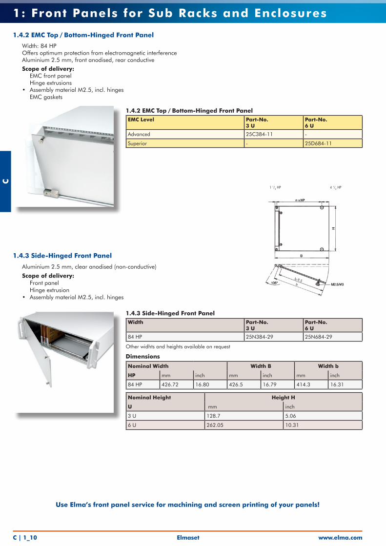
1.4.2 EMC Top / Bottom-Hinged Front Panel
• Width: 84 HP • Offers optimum protection from electromagnetic interference• Aluminium 2.5 mm, front anodised, rear conductive
• Scope of delivery: • EMC front panel • Hinge extrusions • Assembly material M2.5, incl. hinges • EMC gaskets
1.4.3 Side-Hinged Front PanelWidth Part-No.
3 UPart-No. 6 U
84 HP 25N384-29 25N684-29
Other widhts and heights available on request
Dimensions
Nominal Width Width B Width b
HP mm inch mm inch mm inch
84 HP 426.72 16.80 426.5 16.79 414.3 16.31
Nominal Height Height H
U mm inch
3 U 128.7 5.06
6 U 262.05 10.31
1.4.3 Side-Hinged Front Panel
• Aluminium 2.5 mm, clear anodised (non-conductive)
• Scope of delivery: • Front panel • Hinge extrusion • Assembly material M2.5, incl. hinges
1 1/2 HP 4 1/2 HP
b-9.5b
Elmasetwww.elma.com C | 1_11
C1: Front Panels for Sub Racks and Enclosures
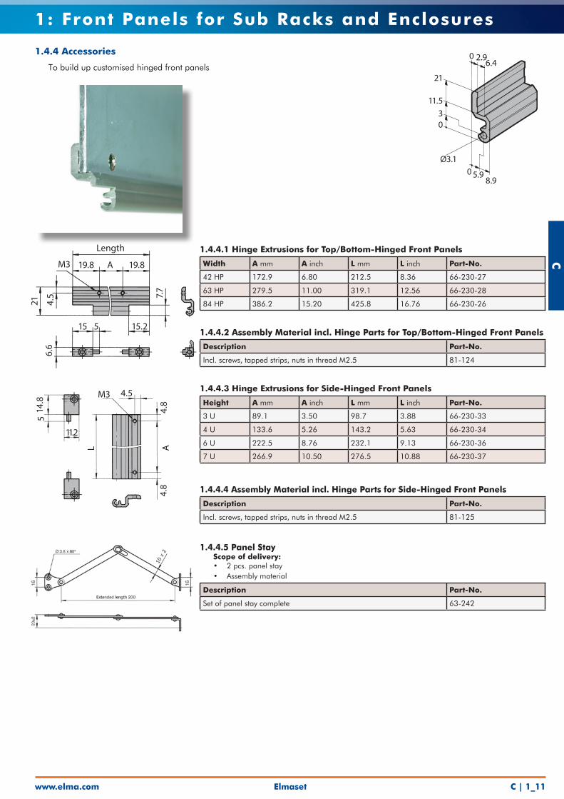
1.4.4.1 Hinge Extrusions for Top/Bottom-Hinged Front Panels
Width A mm A inch L mm L inch Part-No.
42 HP 172.9 6.80 212.5 8.36 66-230-27
63 HP 279.5 11.00 319.1 12.56 66-230-28
84 HP 386.2 15.20 425.8 16.76 66-230-26
1.4.4.2 Assembly Material incl. Hinge Parts for Top/Bottom-Hinged Front Panels
Description Part-No.
Incl. screws, tapped strips, nuts in thread M2.5 81-124
1.4.4.3 Hinge Extrusions for Side-Hinged Front Panels
Height A mm A inch L mm L inch Part-No.
3 U 89.1 3.50 98.7 3.88 66-230-33
4 U 133.6 5.26 143.2 5.63 66-230-34
6 U 222.5 8.76 232.1 9.13 66-230-36
7 U 266.9 10.50 276.5 10.88 66-230-37
1.4.4.4 Assembly Material incl. Hinge Parts for Side-Hinged Front Panels
Description Part-No.
Incl. screws, tapped strips, nuts in thread M2.5 81-125
1.4.4.5 Panel Stay • Scope of delivery: • 2 pcs. panel stay • Assembly material
Description Part-No.
Set of panel stay complete 63-242
1.4.4 Accessories
• To build up customised hinged front panels0 2.9
6.4
21
11.530
Ø3.10 5.9
8.9
M3 4.5
4.8
A4.
8
11.2
514
.8
L
Length
19.8 A
515 15.2
19.8M3
21 4.5 7.
7
6.6
Related Documents