Local Area Networks Dr. Ramana I.I.T Rajasthan Dr. Ramana ( I.I.T Rajasthan ) Local Area Networks 1 / 27

Data Link Layer
Dec 10, 2015
By reading this document, we can understand the concept of data link layer.
Welcome message from author
This document is posted to help you gain knowledge. Please leave a comment to let me know what you think about it! Share it to your friends and learn new things together.
Transcript
Local Area Networks
Dr. Ramana
I.I.T Rajasthan
Dr. Ramana ( I.I.T Rajasthan ) Local Area Networks 1 / 27
Outline of the Lectures
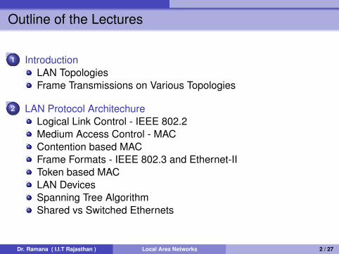
1 IntroductionLAN TopologiesFrame Transmissions on Various Topologies
2 LAN Protocol ArchitechureLogical Link Control - IEEE 802.2Medium Access Control - MACContention based MACFrame Formats - IEEE 802.3 and Ethernet-IIToken based MACLAN DevicesSpanning Tree AlgorithmShared vs Switched Ethernets
Dr. Ramana ( I.I.T Rajasthan ) Local Area Networks 2 / 27
Introduction
Introduction
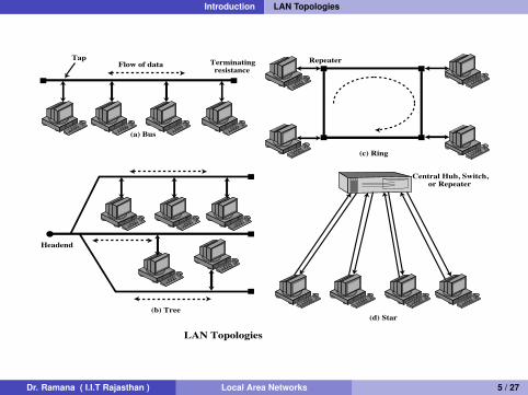
LAN consists of a shared transmission medium and a set ofhardware and software devices for interfacing devices to themedium.A medium access mechanism is needed to allow an orderlyaccess to the shared medium.Size is restricted to few kilometers.Owned by a single organization.Used mainly for carrying data traffic.Data rates are higher and ranges from 100 Mbps to 10 Gbps.Key elements:
Topology - bus,ring,tree,star,Transmission medium - coax,twistedpair,optical fiber, wireless,Medium access control - round-robin, reservation, contention
Dr. Ramana ( I.I.T Rajasthan ) Local Area Networks 3 / 27
Introduction
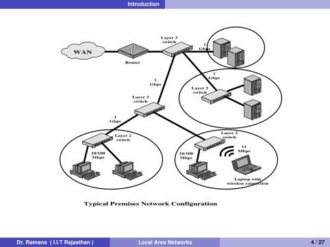
WAN
Router
Layer 3switch
Layer 3switch
Layer 2switch
10/100Mbps
10/100Mbps
Typical Premises Network Configuration
11Mbps
1Gbps
1Gbps
1Gbps
1Gbps
Laptop withwireless connection
Layer 2switch
Layer 2switch
Dr. Ramana ( I.I.T Rajasthan ) Local Area Networks 4 / 27
Introduction LAN Topologies
(d) Star
Central Hub, Switch,or Repeater
LAN Topologies
(a) Bus
Terminatingresistance
Tap RepeaterFlow of data
(c) Ring
(b) Tree
Headend
Dr. Ramana ( I.I.T Rajasthan ) Local Area Networks 5 / 27
Introduction Frame Transmissions on Various Topologies
A
A
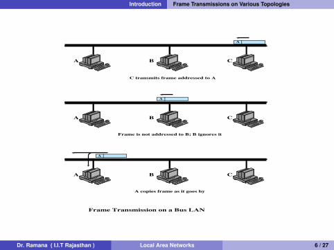
C transmits frame addressed to A
Frame is not addressed to B; B ignores it
A copies frame as it goes by
A
A
Frame Transmission on a Bus LAN
B C
A B C
A B C
Dr. Ramana ( I.I.T Rajasthan ) Local Area Networks 6 / 27
Introduction Frame Transmissions on Various Topologies
C
A
B A
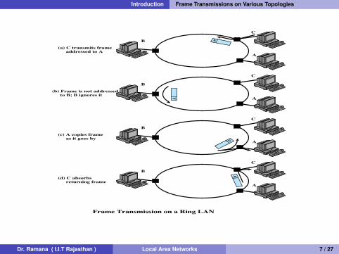
(a) C transmits frame addressed to A
(b) Frame is not addressed to B; B ignores it
(c) A copies frame as it goes by
(d) C absorbs returning frame
Frame Transmission on a Ring LAN
C
A
B
A
C
A
B
A
C
A
B
A
Dr. Ramana ( I.I.T Rajasthan ) Local Area Networks 7 / 27
LAN Protocol Architechure
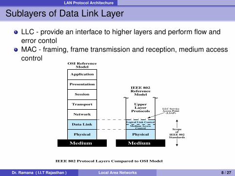
Sublayers of Data Link Layer
LLC - provide an interface to higher layers and perform flow anderror contolMAC - framing, frame transmission and reception, medium accesscontrol
Physical
Data Link
Medium
Network
Transport
Session
Presentation
Application
OSI ReferenceModel
Physical
Medium AccessControl
Medium
Logical Link Control( ) ( ) ( )
UpperLayer
ProtocolsLLC ServiceAccess Point
(LSAP)
Scopeof
IEEE 802Standards
IEEE 802 Protocol Layers Compared to OSI Model
IEEE 802Reference
Model
Dr. Ramana ( I.I.T Rajasthan ) Local Area Networks 8 / 27
LAN Protocol Architechure
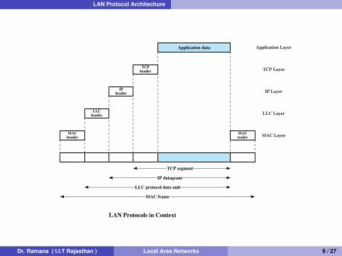
TCP segment
IP datagram
LLC protocol data unit
MAC frame
Application data
TCPheader
IPheader
LLCheader
MACheader
MACtrailer
LAN Protocols in Context
Application Layer
TCP Layer
IP Layer
LLC Layer
MAC Layer
Dr. Ramana ( I.I.T Rajasthan ) Local Area Networks 9 / 27
LAN Protocol Architechure Logical Link Control - IEEE 802.2
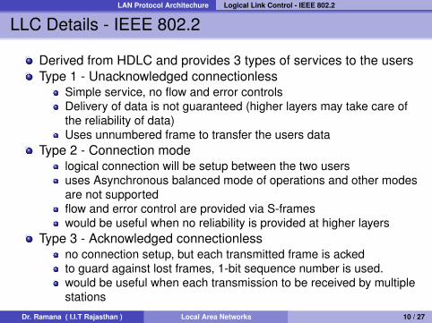
LLC Details - IEEE 802.2
Derived from HDLC and provides 3 types of services to the usersType 1 - Unacknowledged connectionless
Simple service, no flow and error controlsDelivery of data is not guaranteed (higher layers may take care ofthe reliability of data)Uses unnumbered frame to transfer the users data
Type 2 - Connection modelogical connection will be setup between the two usersuses Asynchronous balanced mode of operations and other modesare not supportedflow and error control are provided via S-frameswould be useful when no reliability is provided at higher layers
Type 3 - Acknowledged connectionlessno connection setup, but each transmitted frame is ackedto guard against lost frames, 1-bit sequence number is used.would be useful when each transmission to be received by multiplestations
Dr. Ramana ( I.I.T Rajasthan ) Local Area Networks 10 / 27
LAN Protocol Architechure Medium Access Control - MAC
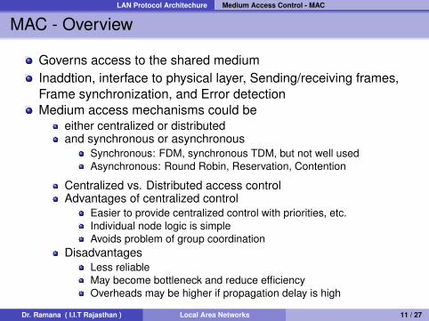
MAC - Overview
Governs access to the shared mediumInaddtion, interface to physical layer, Sending/receiving frames,Frame synchronization, and Error detectionMedium access mechanisms could be
either centralized or distributedand synchronous or asynchronous
Synchronous: FDM, synchronous TDM, but not well usedAsynchronous: Round Robin, Reservation, Contention
Centralized vs. Distributed access controlAdvantages of centralized control
Easier to provide centralized control with priorities, etc.Individual node logic is simpleAvoids problem of group coordination
DisadvantagesLess reliableMay become bottleneck and reduce efficiencyOverheads may be higher if propagation delay is high
Dr. Ramana ( I.I.T Rajasthan ) Local Area Networks 11 / 27
LAN Protocol Architechure Medium Access Control - MAC
(Cont.)
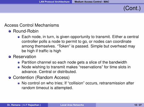
Access Control MechanismsRound-Robin
Each node, in turn, is given opportunity to transmit. Either a centralcontroller polls a node to permit to go, or nodes can coordinateamong themselves. “Token” is passed. Simple but overhead maybe high if traffic is high
ReservationPartition channel so each node gets a slice of the bandwidthNode wishing to transmit makes “reservations” for time slots inadvance. Central or distributed.
Contention (Random Access)No control on who tries; If “collision” occurs, retransmission afterrandom timeout is attempted.
Dr. Ramana ( I.I.T Rajasthan ) Local Area Networks 12 / 27
LAN Protocol Architechure Contention based MAC
Contention based MAC - Overview
All the nodes contend for the medium. No control is exercised todetermine whose turn it is.Simple to implment and suitable for bursty traffic in low andmoderate traffic volumes.Performance may collapse under heavy loads.Example: Aloha, Slotted Aloha, CSMA, 1 persistent, p-persistent,non-persistent CSMA, CSMA/CD, CSMA/CACSMA-Carrier Sense Multiple Access, CD - Collision Detection,CA - Collision Avoidance
Dr. Ramana ( I.I.T Rajasthan ) Local Area Networks 13 / 27
LAN Protocol Architechure Contention based MAC
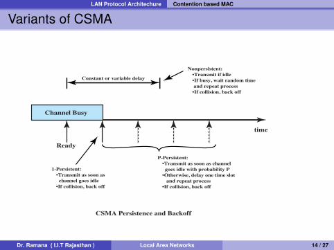
Variants of CSMA
Channel Busy
CSMA Persistence and Backoff
Ready
1-Persistent: •Transmit as soon as channel goes idle •If collision, back off
Nonpersistent: •Transmit if idle •If busy, wait random time and repeat process •If collision, back off
Constant or variable delay
P-Persistent: •Transmit as soon as channel goes idle with probability P •Otherwise, delay one time slot and repeat process •If collision, back off
time
Dr. Ramana ( I.I.T Rajasthan ) Local Area Networks 14 / 27
LAN Protocol Architechure Contention based MAC
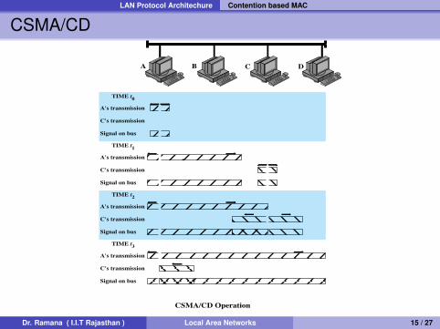
CSMA/CD
B
CSMA/CD Operation
A DC
A's transmission
C's transmission
Signal on bus
TIME t0
A's transmission
C's transmission
Signal on bus
TIME t1
A's transmission
C's transmission
Signal on bus
TIME t2
A's transmission
C's transmission
Signal on bus
TIME t3
Dr. Ramana ( I.I.T Rajasthan ) Local Area Networks 15 / 27
LAN Protocol Architechure Contention based MAC
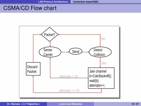
CSMA/CD Flow chart
Packet?
Sense Carrier
Discard Packet
Send Detect Collision
Jam channel b=CalcBackoff(); wait(b);attempts++;
No
Yes
attempts < 16
attempts == 16
Dr. Ramana ( I.I.T Rajasthan ) Local Area Networks 16 / 27
LAN Protocol Architechure Contention based MAC
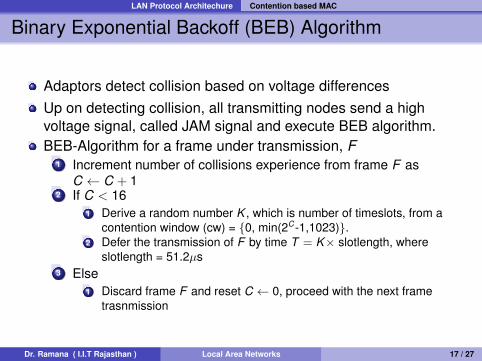
Binary Exponential Backoff (BEB) Algorithm
Adaptors detect collision based on voltage differencesUp on detecting collision, all transmitting nodes send a highvoltage signal, called JAM signal and execute BEB algorithm.BEB-Algorithm for a frame under transmission, F
1 Increment number of collisions experience from frame F asC ← C + 1
2 If C < 161 Derive a random number K , which is number of timeslots, from a
contention window (cw) = {0, min(2C-1,1023)}.2 Defer the transmission of F by time T = K× slotlength, where
slotlength = 51.2µs3 Else
1 Discard frame F and reset C ← 0, proceed with the next frametrasnmission
Dr. Ramana ( I.I.T Rajasthan ) Local Area Networks 17 / 27
LAN Protocol Architechure Contention based MAC
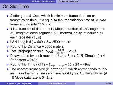
On Slot Time
Slotlength = 51.2µs, which is minimum frame duration ortransmission time. It is equal to the transmission time of 64-byteframe at date rate 10Mbps.It is a function of datarate (10 Mbps), number of LAN segments(5), length of each segment (500 meters), delay introduced byeach repeater (3 µs)LAN Length (L) = 500 x 5 = 2500 metersRound Trip Distance = 5000 metersTotal propagation time (tprop) = 5000
2×108 = 25µsDelay added by each repeater (trep) = 3µs x 2 (Bi-Direction) x 4Repeaters = 24µsRound Trip Time (RTT) = tprop + trep = 25 + 24 = 49µs.The nearest frame size (in power of 2) which corresponds to thisminimum frame transmission time is 64 bytes. So the slottime @10 Mbps data rate is 51.2µs.
Dr. Ramana ( I.I.T Rajasthan ) Local Area Networks 18 / 27
LAN Protocol Architechure Frame Formats - IEEE 802.3 and Ethernet-II
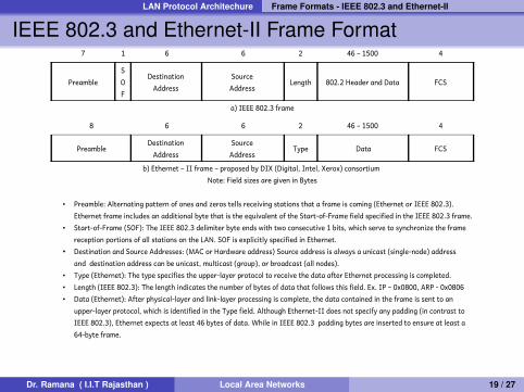
IEEE 802.3 and Ethernet-II Frame Format7 1 6 6 2 46 – 1500 4
PreambleSOF
Destination Address
Source Address
Length 802.2 Header and Data FCS
a) IEEE 802.3 frame
8 6 6 2 46 – 1500 4
PreambleDestination
Address Source
Address Type Data FCS
b) Ethernet – II frame – proposed by DIX (Digital, Intel, Xerox) consortium Note: Field sizes are given in Bytes
• Preamble: Alternating pattern of ones and zeros tells receiving stations that a frame is coming (Ethernet or IEEE 802.3). Ethernet frame includes an additional byte that is the equivalent of the Start-of-Frame field specified in the IEEE 802.3 frame.
• Start-of-Frame (SOF): The IEEE 802.3 delimiter byte ends with two consecutive 1 bits, which serve to synchronize the frame reception portions of all stations on the LAN. SOF is explicitly specified in Ethernet.
• Destination and Source Addresses: (MAC or Hardware address) Source address is always a unicast (single-node) address and destination address can be unicast, multicast (group), or broadcast (all nodes).
• Type (Ethernet): The type specifies the upper-layer protocol to receive the data after Ethernet processing is completed. • Length (IEEE 802.3): The length indicates the number of bytes of data that follows this field. Ex. IP – 0x0800, ARP - 0x0806 • Data (Ethernet): After physical-layer and link-layer processing is complete, the data contained in the frame is sent to an
upper-layer protocol, which is identified in the Type field. Although Ethernet-II does not specify any padding (in contrast to IEEE 802.3), Ethernet expects at least 46 bytes of data. While in IEEE 802.3 padding bytes are inserted to ensure at least a 64-byte frame.
Dr. Ramana ( I.I.T Rajasthan ) Local Area Networks 19 / 27
LAN Protocol Architechure Frame Formats - IEEE 802.3 and Ethernet-II
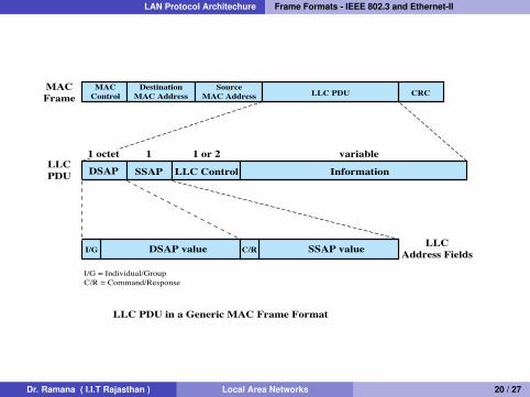
LLC PDU in a Generic MAC Frame Format
MACFrame
LLCAddress FieldsI/G
I/G = Individual/GroupC/R = Command/Response
DSAP value C/R SSAP value
MACControl
DestinationMAC Address
SourceMAC Address LLC PDU CRC
LLCPDU DSAP
1 octet 1 1 or 2 variable
SSAP LLC Control Information
Dr. Ramana ( I.I.T Rajasthan ) Local Area Networks 20 / 27
LAN Protocol Architechure Token based MAC
Token based MAC
Dr. Ramana ( I.I.T Rajasthan ) Local Area Networks 21 / 27
LAN Protocol Architechure LAN Devices
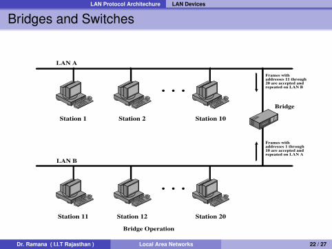
Bridges and Switches
• • •
• • •
LAN A
LAN B
Bridge
Bridge Operation
Frames withaddresses 11 through20 are accepted andrepeated on LAN B
Frames withaddresses 1 through10 are accepted andrepeated on LAN A
Station 1 Station 2 Station 10
Station 11 Station 12 Station 20
Dr. Ramana ( I.I.T Rajasthan ) Local Area Networks 22 / 27
LAN Protocol Architechure LAN Devices
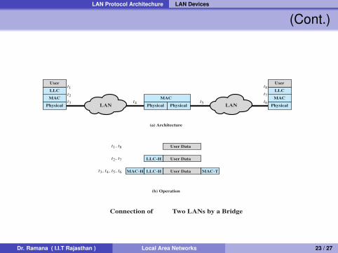
(Cont.)
PhysicalPhysical
MAC
MAC-H LLC-H MAC-TUser Data
LLC-H User Data
User Data
LLC
Usert1
t3, t4, t5, t6
t2, t7
t1, t8
t2t3 t4 t5 t6
t7
t8
Physical
MAC
LLC
User
MAC
(a) Architecture
(b) Operation
Connection of Two LANs by a Bridge
PhysicalLAN LAN
Dr. Ramana ( I.I.T Rajasthan ) Local Area Networks 23 / 27
LAN Protocol Architechure Spanning Tree Algorithm
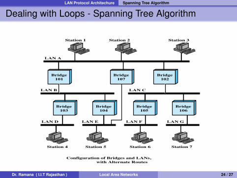
Dealing with Loops - Spanning Tree Algorithm
LAN A
LAN B LAN C
LAN D LAN E LAN GLAN F
Bridge101
Bridge107
Bridge102
Bridge103
Bridge104
Bridge105
Bridge106
Station 1
Station 4 Station 5 Station 6 Station 7
Station 2 Station 3
Configuration of Bridges and LANs, with Alternate Routes
Dr. Ramana ( I.I.T Rajasthan ) Local Area Networks 24 / 27
LAN Protocol Architechure Spanning Tree Algorithm
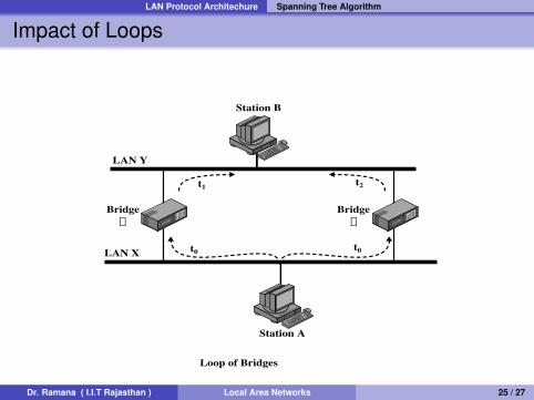
Impact of Loops
LAN Y
LAN X
Bridgea
Bridgeb
t2t1
t0 t0
Station B
Station A
Loop of Bridges
Dr. Ramana ( I.I.T Rajasthan ) Local Area Networks 25 / 27
LAN Protocol Architechure Shared vs Switched Ethernets
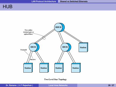
HUB
Station Station Station Station
Station
HHUB
Two-Level Star Topology
IHUBIHUB
Two cables(twisted pair or
optical fiber)
Transmit
Receive
Dr. Ramana ( I.I.T Rajasthan ) Local Area Networks 26 / 27
LAN Protocol Architechure Shared vs Switched Ethernets
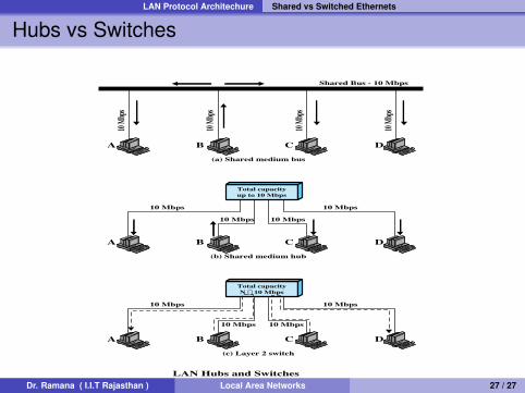
Hubs vs Switches
Shared Bus - 10 Mbps
10 Mb
ps
10 Mb
ps
10 Mb
ps
10 Mb
ps
A B C D
(a) Shared medium bus
A B C D
(b) Shared medium hub
10 Mbps 10 Mbps
10 Mbps10 Mbps
Total capacityup to 10 Mbps
A B C D
(c) Layer 2 switch
10 Mbps 10 Mbps
10 Mbps10 Mbps
Total capacityN ¥ 10 Mbps
LAN Hubs and SwitchesDr. Ramana ( I.I.T Rajasthan ) Local Area Networks 27 / 27
Related Documents