Application Note R12AN0043EU0114 Rev.1.14 Page 1 of 17 Mar 1, 2018 Renesas Synergy™ Platform CTSU Slider Example on DK-S124 Introduction The Capacitive Touch Sensing Unit (CTSU) application note demonstrates the slider and button functionality on Renesas Synergy ™ MCU Groups, and uses the DK-S124 v2.0 and v3.0 as examples. It covers how to bring up the CTSU slider functionality using the CTSU framework on Synergy Software Platform (SSP) v1.4.0 or later. Prerequisites You should have some experience with either the Synergy e 2 studio or the IAR Embedded Workbench ® for Renesas Synergy™ (IAR EW for Synergy), Integrated Solutions Development Environment (ISDE). The program may be compiled and run using either tool chain. You should also be familiar with the SSP and its concepts, such as frameworks, callback functions and APIs. For a conceptual overview, see section 2.1, for the SSP Architecture, in the SSP User’s Manual. Before you use this application note, you may want to build and run the Blinky project in your board’s Quick Start Guide. By doing so, you will become familiar with building and running SSP applications while ensuring the debug connection to your board is functioning properly. It should take about two hours to complete the topics below and bring up the sample project. • SSP capacitive touch framework overview • CTSU application configuration data overview • Procedure to recreate the sample project: Generating a new project with no RTOS included. Creating the CTSU thread. Creating the CTSU slider framework. Creating the CTSU button framework. Copying over the CTSU configuration files. Creating the callback function. Required Resources To build and run the application, you will need: • A Synergy DK-S124 v2.0 or v3.0 MCU kit • SSP v1.4.0 or later • e 2 studio v6.2.0 • IAR EW for Synergy v8.21.1 with SSC v6.2.0 You can download the required Renesas software from the Renesas Synergy Gallery (https://synergygallery.renesas.com). R12AN0043EU0114 Rev.1.14 Mar 1, 2018

Welcome message from author
This document is posted to help you gain knowledge. Please leave a comment to let me know what you think about it! Share it to your friends and learn new things together.
Transcript
Application Note
R12AN0043EU0114 Rev.1.14 Page 1 of 17 Mar 1, 2018
Renesas Synergy™ Platform
CTSU Slider Example on DK-S124 Introduction The Capacitive Touch Sensing Unit (CTSU) application note demonstrates the slider and button functionality on Renesas Synergy™ MCU Groups, and uses the DK-S124 v2.0 and v3.0 as examples. It covers how to bring up the CTSU slider functionality using the CTSU framework on Synergy Software Platform (SSP) v1.4.0 or later.
Prerequisites You should have some experience with either the Synergy e2 studio or the IAR Embedded Workbench® for Renesas Synergy™ (IAR EW for Synergy), Integrated Solutions Development Environment (ISDE). The program may be compiled and run using either tool chain. You should also be familiar with the SSP and its concepts, such as frameworks, callback functions and APIs. For a conceptual overview, see section 2.1, for the SSP Architecture, in the SSP User’s Manual.
Before you use this application note, you may want to build and run the Blinky project in your board’s Quick Start Guide. By doing so, you will become familiar with building and running SSP applications while ensuring the debug connection to your board is functioning properly.
It should take about two hours to complete the topics below and bring up the sample project.
• SSP capacitive touch framework overview • CTSU application configuration data overview • Procedure to recreate the sample project:
Generating a new project with no RTOS included. Creating the CTSU thread. Creating the CTSU slider framework. Creating the CTSU button framework. Copying over the CTSU configuration files. Creating the callback function.
Required Resources To build and run the application, you will need:
• A Synergy DK-S124 v2.0 or v3.0 MCU kit • SSP v1.4.0 or later • e2 studio v6.2.0 • IAR EW for Synergy v8.21.1 with SSC v6.2.0 You can download the required Renesas software from the Renesas Synergy Gallery (https://synergygallery.renesas.com).
R12AN0043EU0114 Rev.1.14
Mar 1, 2018
Renesas Synergy™ Platform CTSU Slider Example on DK-S124
R12AN0043EU0114 Rev.1.14 Page 2 of 17 Mar 1, 2018
Contents
1. CTSU Overview ....................................................................................................................... 2
2. Capacitive Touch SSP Framework Overview........................................................................... 4 2.1 Resources Used in the Capacitive Touch SSP Framework .................................................................... 4 2.2 Understanding the SSP Slider and Button Framework ........................................................................... 4 2.3 CTSU Configuration Data ........................................................................................................................ 5
3. Building the CTSU Slider Application ....................................................................................... 5 3.1 Handling the Slider and Button Callback ................................................................................................. 5 3.2 Detection of User Sliding Motion ............................................................................................................. 6 3.3 Step-by-Step Procedure to Recreate the Sample Project ...................................................................... 7
4. Conclusion ............................................................................................................................. 16
1. CTSU Overview The Capacitive Touch Sensing Unit (CTSU) measures the electrostatic capacitance of a touch sensor. Changes in electrostatic capacitance are determined by software that enables the CTSU to detect whether a finger is in contact with the touch sensor. Electrostatic capacitance is detected by self-capacitance and mutual capacitance methods. This application note uses the self-capacitance single-scan mode for the slider and button functionality.
Table 1 summarizes the specification of the CTSU on DK-S124 Synergy MCU kit. For details, see the S124 User’s Manual.
Table 1 CTSU Specification
Item Description Operating clock PCLKB, PCLKB/2, or PCLKB/4 Pins Electrostatic capacitance
measurement 31 channels (TS00 to TS28, TS30, TS31)
TSCAP Low-pass filter (LPF) connection pin Measurement modes
Self-capacitance single-scan mode Electrostatic capacitance is measured on one channel using the self-capacitance method
Self-capacitance multi-scan mode Electrostatic capacitance is measured on multiple channels successively using the self-capacitance method
Mutual capacitance full scan mode Electrostatic capacitance is measured successively on multiple channels using the mutual capacitance method
Noise prevention Synchronous noise prevention, high-pass noise prevention
Measurement start conditions • Software trigger • External trigger (ELC_CTSU from the
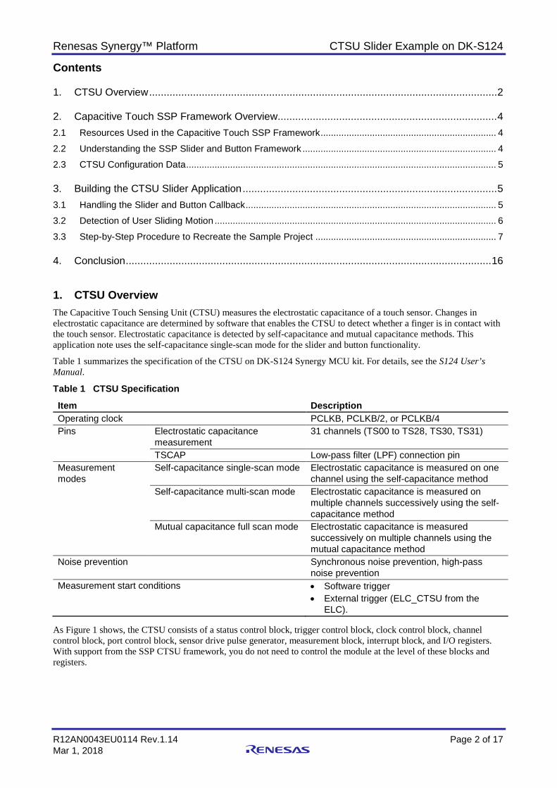
ELC). As Figure 1 shows, the CTSU consists of a status control block, trigger control block, clock control block, channel control block, port control block, sensor drive pulse generator, measurement block, interrupt block, and I/O registers. With support from the SSP CTSU framework, you do not need to control the module at the level of these blocks and registers.
Renesas Synergy™ Platform CTSU Slider Example on DK-S124
R12AN0043EU0114 Rev.1.14 Page 3 of 17 Mar 1, 2018
Figure 1 CTSU block diagram The slider functionality commonly involves detecting the sliding motion and responding to the motion. In this application project, the example detects a user sliding a finger on the slider and responds by lighting up the three onboard LEDs. When you slide a finger from the tip (sharp end) of the slider to the end (wide end) of the slider, the three onboard LEDs light up from dim to bright. The button functionality involves detection of button press detection and response. The example project detects press on button 1 and responds by toggling LED2 (orange), and detects press on button 2 and responds by toggling LED3 (green).
A functioning project in archive format is attached with this application note. You can import the archive (CTSU_Slider_Button_Example.zip file), compile, download, and run to exercise the slider and button functionalities. In addition, this application note provides step by step instructions to use the SSP slider/button framework feature to recreate this application.
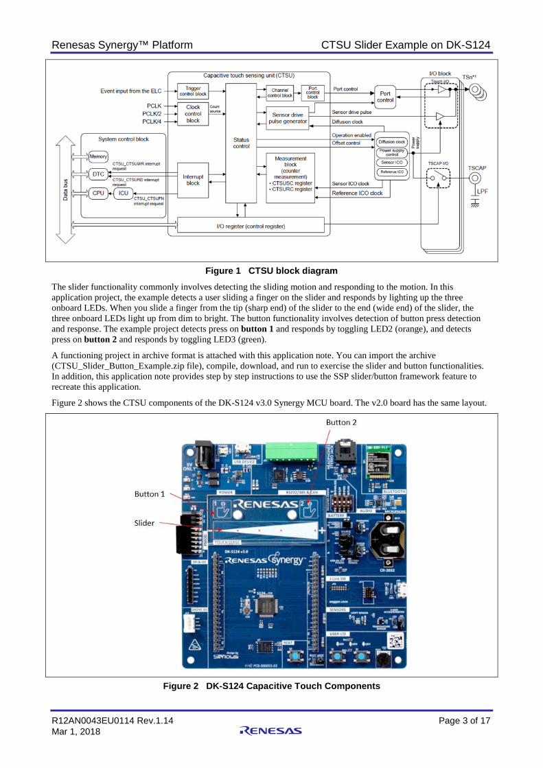
Figure 2 shows the CTSU components of the DK-S124 v3.0 Synergy MCU board. The v2.0 board has the same layout.
Figure 2 DK-S124 Capacitive Touch Components

Renesas Synergy™ Platform CTSU Slider Example on DK-S124
R12AN0043EU0114 Rev.1.14 Page 4 of 17 Mar 1, 2018
2. Capacitive Touch SSP Framework Overview The capacitive touch slider framework interprets the CTSU data for all the slider configurations initialized by the system. The capacitive touch slider framework registers a callback with the CTSU framework layer, that is called each time the processed data is available. The slider framework uses this data (raw values) to determine if a touch or release occurred and, if so, where it has occurred. If there is a state change, the framework calls the callback for each slider with the event and position, in the order as they are present in the slider configuration table. This application note uses only the single slider that is available on the DK-S124 Synergy MCU board.
2.1 Resources Used in the Capacitive Touch SSP Framework Table 2 Resources used in CTSU framework interface
Resource ISDE Tab Selection Framework CTSU Driver Threads Framework > Input > CTSU Framework on sf_touch_ctsu
SSP v1.4.0 or later supports S7G2, S3A7, S5D9, and S124 Synergy MCU boards. This application note focuses on the capacitive touch slider framework implemented on S124 with DK-S124 MCU kit. Table 3 and Table 4 show additional resources used by the slider framework.
Table 3 Additional resources used in CTSU slider framework interface
Resource ISDE Tab Selection Framework CTSU Slider Driver Threads Framework > Input > Cap Touch Slider/Wheel
Framework on sf_touch_ctsu_slider CTSU HAL Driver Threads —
Table 4 Additional resources used in CTSU button framework interface
Resource ISDE Tab Selection Framework CTSU Button Driver Threads Framework >Input > Cap Touch Button Framework
on sf_touch_ctsu_button CTSU HAL Driver Threads —
2.2 Understanding the SSP Slider and Button Framework The SSP CTSU slider framework generates the events after touch data processing. This application example creates a response when SF_TOUCH_CTSU_SLIDER_STATE_HELD is triggered. By looking at the reported position on the slider, you can create the desired response in the callback function when a sliding motion from the user is detected.
Table 5 CTSU slider states
Name Description SF_TOUCH_CTSU_SLIDER_STATE_NO_CHANGE Slider is in the released state SF_TOUCH_CTSU_SLIDER_STATE_INITIALIZED Slider is in the pressed state SF_TOUCH_CTSU_SLIDER_STATE_TOUCHED Slider is pressed SF_TOUCH_CTSU_SLIDER_STATE_RELEASED Slider is released SF_TOUCH_CTSU_SLIDER_STATE_CLOSED Slider has been disabled and will no longer
generate events SF_TOUCH_CTSU_SLIDER_STATE_MULTI_TOUCH More than one touch element is being touched SF_TOUCH_CTSU_SLIDER_STATE_DISABLED Slider is disabled from being updated SF_TOUCH_CTSU_SLIDER_STATE_HELD Slider is held (continued press)
The SSP CTSU button framework generates the events in the following table after the touch data processing.
Table 6 CTSU button states
Name Description TOUCH_BUTTON_STATE_RELEASED Button is in the released state TOUCH_BUTTON_STATE_PRESSED Button is in the pressed state

Renesas Synergy™ Platform CTSU Slider Example on DK-S124
R12AN0043EU0114 Rev.1.14 Page 5 of 17 Mar 1, 2018
Name Description TOUCH_BUTTON_STATE_LONG_HOLD Button is pressed down for a long time
(duration in sf_touch_ctsu_button_config.h)
TOUCH_BUTTON_STATE_STUCK Button is pressed down for a short time (duration in sf_touch_ctsu_button_config.h)
TOUCH_BUTTON_STATE_INITIAL Button has been initialized successfully TOUCH_BUTTON_STATE_CLOSING Button has been disabled and will no longer
generate events TOUCH_BUTTON_STATE_MULTI_TOUCH More than one touch element is being touched TOUCH_BUTTON_STATE_DISABLED Button is disabled from being updated
2.3 CTSU Configuration Data The sample project includes a set of CTSU configuration data under \CTSU_Slider_Button_Example\src\captouch_configs\. The CTSU configuration data is specific to DK-S124 hardware. Section 3.3 is a step by step instruction to recreate the sample project. Step 7 requires you to copy this \captouch_config folder to the new application you will be creating.
3. Building the CTSU Slider Application This section provides details on generating a CTSU slider and button application with the e2 studio ISDE and the SSP. With the slider/button framework support from the SSP package, your application only needs to handle the callbacks from CTSU events without requiring any low-level software to handle the CTSU registers and basic capacitive touch processing functions.
The next section describes the callback functions implemented in the sample project and can serve as a reference for your application. Section 3.2 details the sliding motion detection method used. You can use and adjust this method based on the requirements of your unique application. To illustrate the process of establishing a slider/button application, section 3.3 provides a step-by-step instruction to recreate the sample project included. You can take similar steps to add the CTSU component to your existing application or use this sample project as a starting point for your application.
For details, see the sample project package CTSU_Slider_Button_Example.zip.
3.1 Handling the Slider and Button Callback The example project implemented the slider and button callback functions in ctsu_thread_entry.c located in the sample project folder \CTSU_Slider_Button_Example\src\ folder. The ctsu_thread_entry.c is generated by the Synergy configurator. Table 7 provides a summary of the functions implemented in the ctsu_thread_entry.c. These functions provide the major functionalities you need to create with the SSP slider and button framework to establish a typical slider and button application.
Section 3.3 is a step-by-step instruction to recreate the sample project. You can copy the ctsu_thread_entry.c file to the new application and modify the response to the sliding motion and button press events as desired.
Renesas Synergy™ Platform CTSU Slider Example on DK-S124
R12AN0043EU0114 Rev.1.14 Page 6 of 17 Mar 1, 2018
Table 7 Functions in ctsu_thread_entry.c
Functions Description g_button_framework_user_callback Button touch callback function (defined with the Synergy
configurator) implementation g_slider_framework_user_callback Slider touch callback function (defined with the Synergy
configurator) implementation CB_Self_Slider_0 • Sub function called from
g_slider_framework_user_callback • Implements response to events listed in Table
CB_Self_Button_processing
• Sub function called from g_button_framework_user_callback
• Activated when Button 1 is touched • Implements response to events listed in Table
pwm_led_brightening • Subfunction called from ctsu_thread_entry • Light up the LED from dim to bright.
The sliding motion detection is implemented in function CB_Self_Slider_0. This function is called from the g_button_framework_user_callback. It responds to the slider event described in Table 5.
In the handling of the SF_TOUCH_CTSU_SLIDER_STATE_HELD state, an algorithm has been implemented to detect the sliding motion, as explained in the following section. To perform sliding motion detection, the user application must perform a small amount of position data processing. For button press detection, no data processing needs to be done by the user. This application note does not detail button press detection.
3.2 Detection of User Sliding Motion In the sample project, the following macro definitions, function definition, and variables are used in sliding motion detection.
Figure 9 shows the macro definitions are determined based on the Update Hz setting and how fast you want to guide the user’s sliding motion across the slider. The slider position is reported as 100*number of sensors. In case of the DK-S124, numbering of the sensors from left to right is 1, 2, 3, 4, and 5. The reported position then would be in the range of 0-500. The STARTLIMIT and ENDLIMIT are determined based on this calculation. The DETECTIONTIME is related to the Update Hz defined in the Synergy configurator for the CTSU sensing unit.
Section 3.3 is a step-by-step instruction to recreate the sample project. Update Hz is set in Step 3 of Figure 9. When Update Hz increases, the DETECTIONTIME should increase to allow a reasonable number of times for the detections of the sliding motion.
#define SIZEOFBUFFER 600 /* slider position temporary buffer size*/ #define DETECTIONTIME 8 /* after detection of 8 times of finger movement detected, a sliding motion is identified */ #define STARTLIMIT 100 /* has to be less than this threshold to identify as a starting point of a sliding motion */ #define ENDLIMIT 400 /* has to be greater than this threshold to identify an ending point of a sliding motion */ void CB_Self_Slider_0(sf_touch_ctsu_slider_callback_args_t * p_args); static uint32_t detect_count = 0; /* track the number of position movement detected */ volatile uint32_t result[SIZEOFBUFFER]; /* temporary storage for the slider position */ static uint32_t slider_data_index = 0; /* index into the result array */ int diff = 0; /* position difference between two neighboring slider position results */
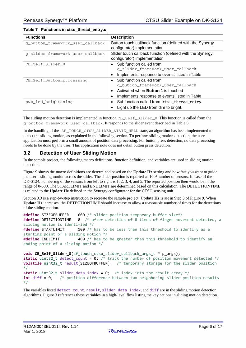
The variables listed detect_count, result, slider_data_index, and diff are in the sliding motion detection algorithms. Figure 3 references these variables in a high-level flow listing the key actions in sliding motion detection.
Renesas Synergy™ Platform CTSU Slider Example on DK-S124
R12AN0043EU0114 Rev.1.14 Page 7 of 17 Mar 1, 2018
Figure 3 Sliding motion detection
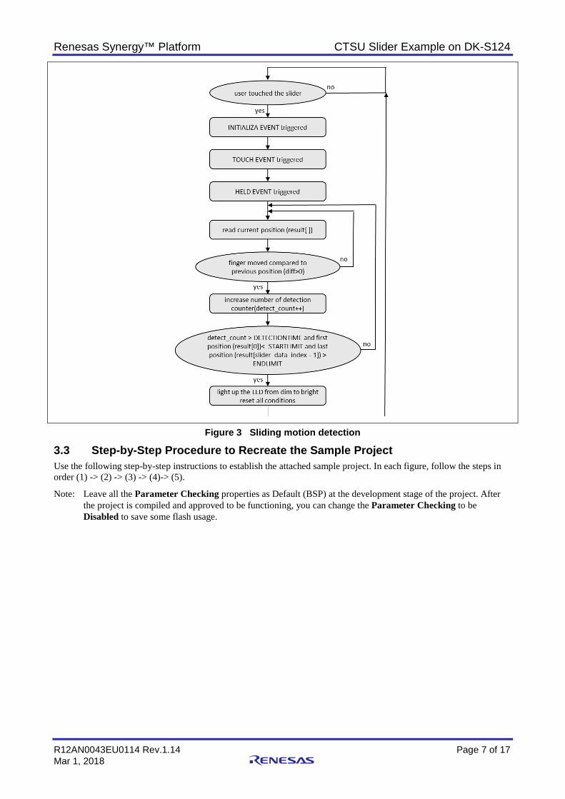
3.3 Step-by-Step Procedure to Recreate the Sample Project Use the following step-by-step instructions to establish the attached sample project. In each figure, follow the steps in order (1) -> (2) -> (3) -> (4)-> (5).
Note: Leave all the Parameter Checking properties as Default (BSP) at the development stage of the project. After the project is compiled and approved to be functioning, you can change the Parameter Checking to be Disabled to save some flash usage.
Renesas Synergy™ Platform CTSU Slider Example on DK-S124
R12AN0043EU0114 Rev.1.14 Page 8 of 17 Mar 1, 2018
Figure 4 Parameter Checking Setting Step 1: Establishing a new project with no RTOS included:
1. Create a new Synergy Project. 2. Select ‘Renesas Synergy C Executable Project’ 3. Enter the project name and setup the Synergy license file.
See Importing a Renesas Synergy Project (r11an0023eu0119-synergy-ssp-import-guide.pdf) included with this application project to setup the Synergy license.
Figure 5 Generate a new project
Renesas Synergy™ Platform CTSU Slider Example on DK-S124
R12AN0043EU0114 Rev.1.14 Page 9 of 17 Mar 1, 2018
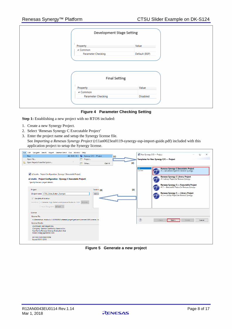
4. Choose board S124 DK. 5. Choose BSP.
Figure 6 Choose the Board and BSP package Step 2: Create the CTSU thread.
1. Updated the heap size (bytes) property from the default 0x1000 to 0x0. 2. Under the Threads tab, click the ‘+’ sign to create a new thread.
Figure 7 Generate CTSU Thread

Renesas Synergy™ Platform CTSU Slider Example on DK-S124
R12AN0043EU0114 Rev.1.14 Page 10 of 17 Mar 1, 2018
3. Set the property of this new thread.
Figure 8 Configure CTSU Thread
Renesas Synergy™ Platform CTSU Slider Example on DK-S124
R12AN0043EU0114 Rev.1.14 Page 11 of 17 Mar 1, 2018
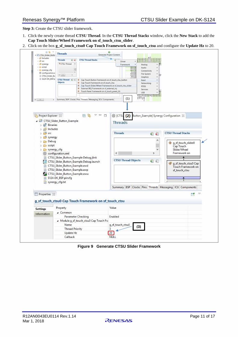
Step 3: Create the CTSU slider framework.
1. Click the newly create thread CTSU Thread. In the CTSU Thread Stacks window, click the New Stack to add the Cap Touch Slider/Wheel Framework on sf_touch_ctsu_slider.
2. Click on the box g_sf_touch_ctsu0 Cap Touch Framework on sf_touch_ctsu and configure the Update Hz to 20.
Figure 9 Generate CTSU Slider Framework
(3)
Renesas Synergy™ Platform CTSU Slider Example on DK-S124
R12AN0043EU0114 Rev.1.14 Page 12 of 17 Mar 1, 2018
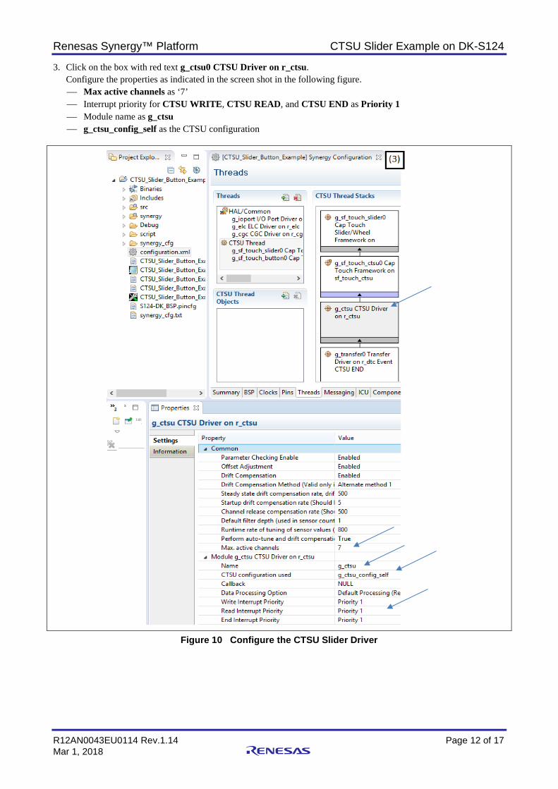
3. Click on the box with red text g_ctsu0 CTSU Driver on r_ctsu. Configure the properties as indicated in the screen shot in the following figure. Max active channels as ‘7’ Interrupt priority for CTSU WRITE, CTSU READ, and CTSU END as Priority 1 Module name as g_ctsu g_ctsu_config_self as the CTSU configuration
Figure 10 Configure the CTSU Slider Driver
Renesas Synergy™ Platform CTSU Slider Example on DK-S124
R12AN0043EU0114 Rev.1.14 Page 13 of 17 Mar 1, 2018
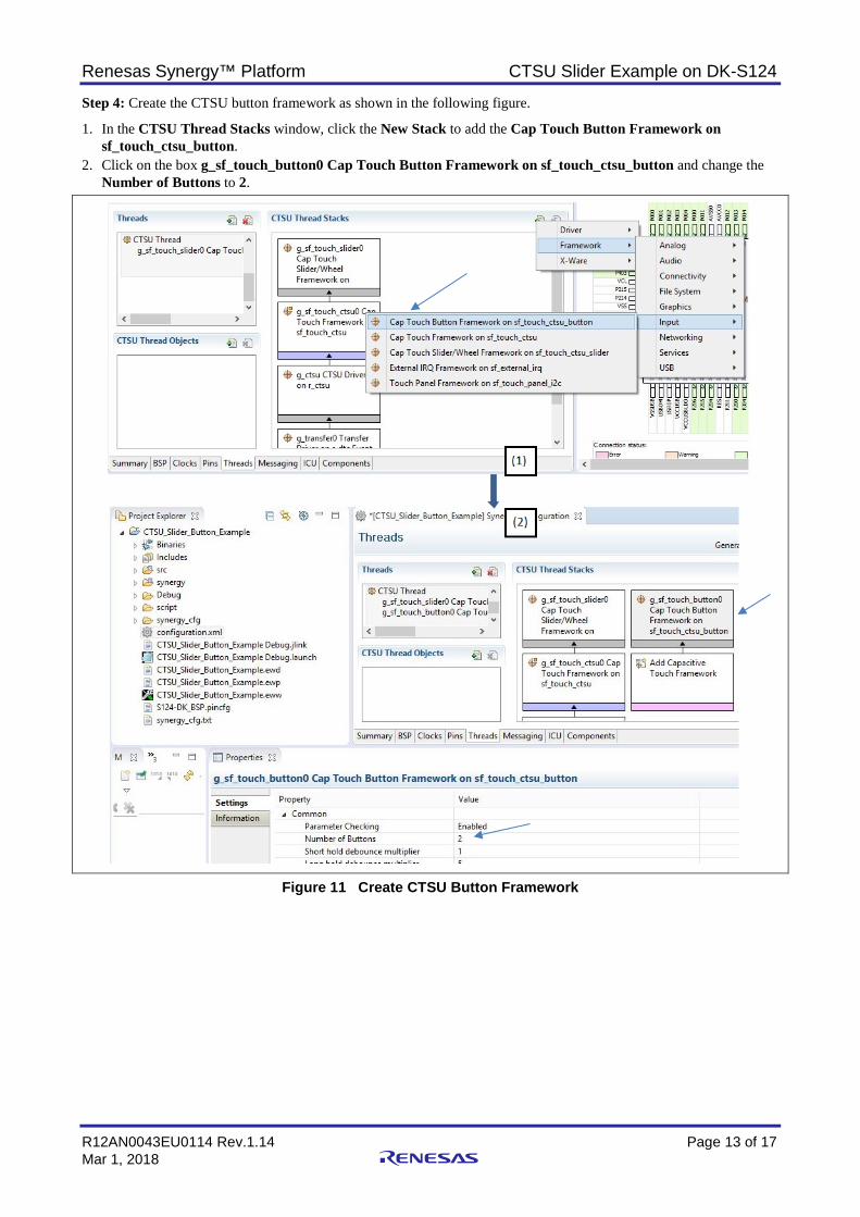
Step 4: Create the CTSU button framework as shown in the following figure.
1. In the CTSU Thread Stacks window, click the New Stack to add the Cap Touch Button Framework on sf_touch_ctsu_button.
2. Click on the box g_sf_touch_button0 Cap Touch Button Framework on sf_touch_ctsu_button and change the Number of Buttons to 2.
Figure 11 Create CTSU Button Framework
Renesas Synergy™ Platform CTSU Slider Example on DK-S124
R12AN0043EU0114 Rev.1.14 Page 14 of 17 Mar 1, 2018
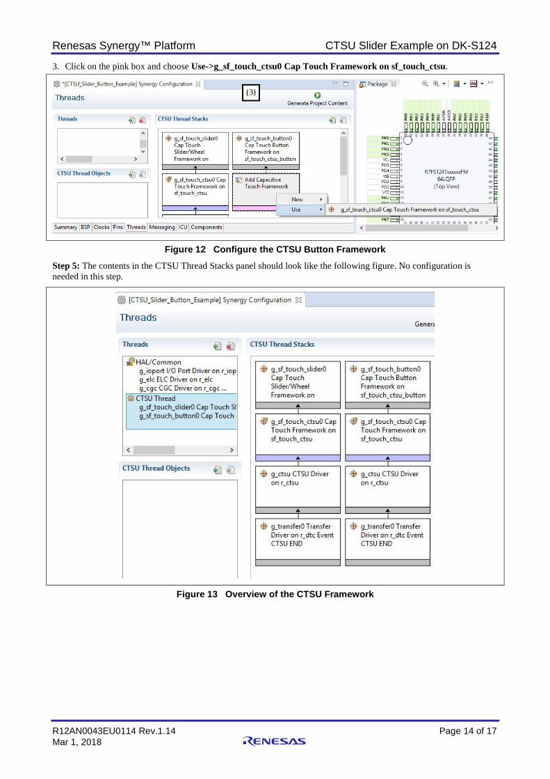
3. Click on the pink box and choose Use->g_sf_touch_ctsu0 Cap Touch Framework on sf_touch_ctsu.
Figure 12 Configure the CTSU Button Framework Step 5: The contents in the CTSU Thread Stacks panel should look like the following figure. No configuration is needed in this step.
Figure 13 Overview of the CTSU Framework

Renesas Synergy™ Platform CTSU Slider Example on DK-S124
R12AN0043EU0114 Rev.1.14 Page 15 of 17 Mar 1, 2018
Step 6: Copy the captouch_configs folder from the imported functioning sample project (under \CTSU_Slider_Button_Example\src\captouch_configs) to your newly created project.
Figure 14 Copy over the CTSU configuration files Step 7: Create the callback function.
In this step, you can copy over ctsu_thread_entry.c (under sample project \CTSU_Slider_Button_Example\src\) to your newly created project.
Figure 15 Copy over the example callback functions

Renesas Synergy™ Platform CTSU Slider Example on DK-S124
R12AN0043EU0114 Rev.1.14 Page 16 of 17 Mar 1, 2018
Step 8: Exercise the project.
Click Generate Project Content from the Synergy configurator, and then compile the project. It should compile without any errors.
Figure 16 Generate Project Content and Build the Project Download and run the project. You can slide your finger from the sharp end to the thick end and see the three LEDs light up from dim to bright upon reaching the thick end. With the sample application, LED2 (orange) toggles on a button 1 press event and LED3 (green) toggles on a button 2 press event.
Step 9: Update all Parameter Checking settings to Disabled as pointed out in Figure 4. Recompile and download to test the project.
4. Conclusion With the support from the SSP CTSU framework and the e2 studio configurator, building a slider application on the Synergy development kit is very easy. The SSP package has the build in CTSU data processing functionality and call back scheme to enable rapid slider and button application development.
Renesas Synergy™ Platform CTSU Slider Example on DK-S124
R12AN0043EU0114 Rev.1.14 Page 17 of 17 Mar 1, 2018
Website and Support Support: https://synergygallery.renesas.com/support
Technical Contact Details:
• America: https://www.renesas.com/en-us/support/contact.html • Europe: https://www.renesas.com/en-eu/support/contact.html • Japan: https://www.renesas.com/ja-jp/support/contact.html
All trademarks and registered trademarks are the property of their respective owners.
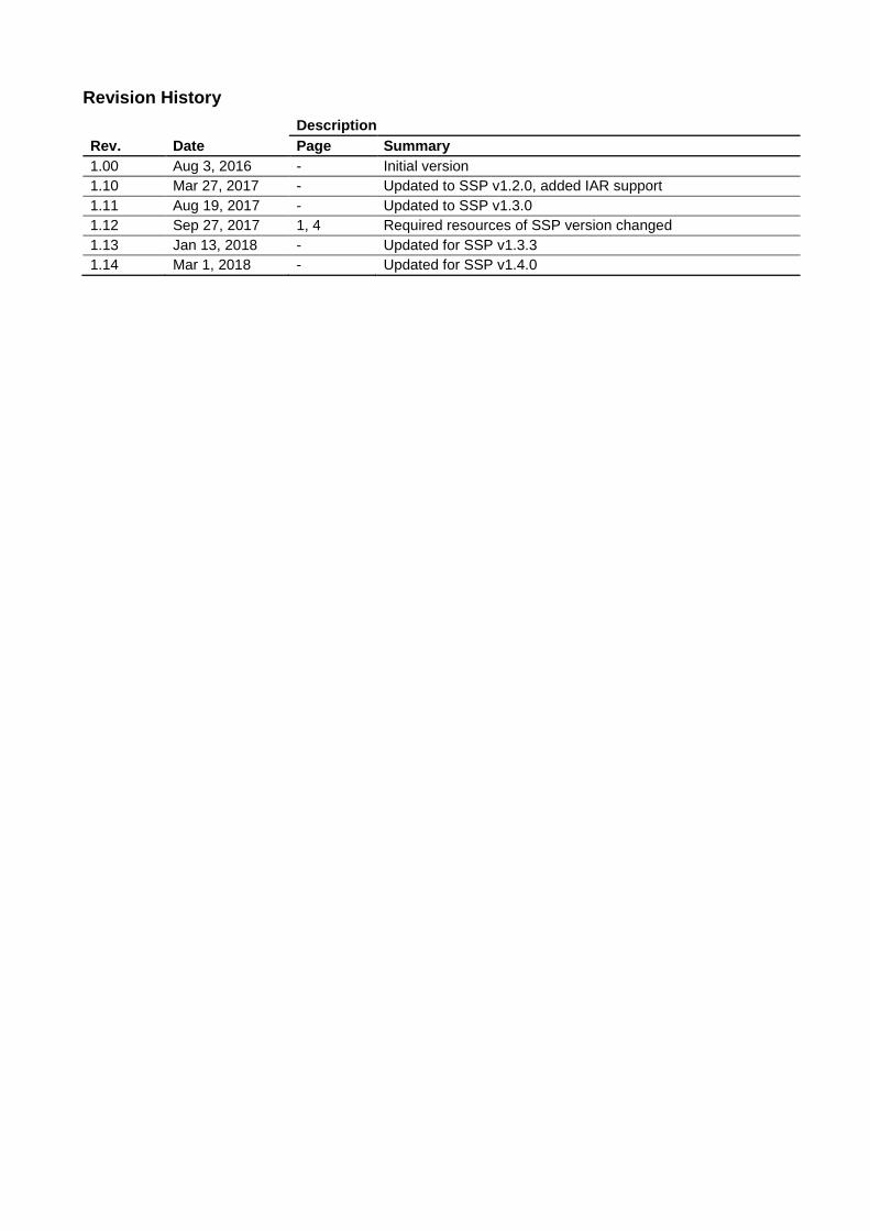
Revision History
Rev. Date Description Page Summary
1.00 Aug 3, 2016 - Initial version 1.10 Mar 27, 2017 - Updated to SSP v1.2.0, added IAR support 1.11 Aug 19, 2017 - Updated to SSP v1.3.0 1.12 Sep 27, 2017 1, 4 Required resources of SSP version changed 1.13 Jan 13, 2018 - Updated for SSP v1.3.3 1.14 Mar 1, 2018 - Updated for SSP v1.4.0

http://www.renesas.comRefer to "http://www.renesas.com/" for the latest and detailed information.
Renesas Electronics America Inc.1001 Murphy Ranch Road, Milpitas, CA 95035, U.S.A.Tel: +1-408-432-8888, Fax: +1-408-434-5351Renesas Electronics Canada Limited9251 Yonge Street, Suite 8309 Richmond Hill, Ontario Canada L4C 9T3Tel: +1-905-237-2004Renesas Electronics Europe LimitedDukes Meadow, Millboard Road, Bourne End, Buckinghamshire, SL8 5FH, U.KTel: +44-1628-651-700, Fax: +44-1628-651-804Renesas Electronics Europe GmbHArcadiastrasse 10, 40472 Düsseldorf, GermanyTel: +49-211-6503-0, Fax: +49-211-6503-1327Renesas Electronics (China) Co., Ltd.Room 1709 Quantum Plaza, No.27 ZhichunLu, Haidian District, Beijing, 100191 P. R. ChinaTel: +86-10-8235-1155, Fax: +86-10-8235-7679Renesas Electronics (Shanghai) Co., Ltd.Unit 301, Tower A, Central Towers, 555 Langao Road, Putuo District, Shanghai, 200333 P. R. ChinaTel: +86-21-2226-0888, Fax: +86-21-2226-0999Renesas Electronics Hong Kong LimitedUnit 1601-1611, 16/F., Tower 2, Grand Century Place, 193 Prince Edward Road West, Mongkok, Kowloon, Hong KongTel: +852-2265-6688, Fax: +852 2886-9022Renesas Electronics Taiwan Co., Ltd.13F, No. 363, Fu Shing North Road, Taipei 10543, TaiwanTel: +886-2-8175-9600, Fax: +886 2-8175-9670Renesas Electronics Singapore Pte. Ltd.80 Bendemeer Road, Unit #06-02 Hyflux Innovation Centre, Singapore 339949Tel: +65-6213-0200, Fax: +65-6213-0300Renesas Electronics Malaysia Sdn.Bhd.Unit 1207, Block B, Menara Amcorp, Amcorp Trade Centre, No. 18, Jln Persiaran Barat, 46050 Petaling Jaya, Selangor Darul Ehsan, MalaysiaTel: +60-3-7955-9390, Fax: +60-3-7955-9510Renesas Electronics India Pvt. Ltd.No.777C, 100 Feet Road, HAL 2nd Stage, Indiranagar, Bangalore 560 038, IndiaTel: +91-80-67208700, Fax: +91-80-67208777Renesas Electronics Korea Co., Ltd.17F, KAMCO Yangjae Tower, 262, Gangnam-daero, Gangnam-gu, Seoul, 06265 KoreaTel: +82-2-558-3737, Fax: +82-2-558-5338
SALES OFFICES
© 2018 Renesas Electronics Corporation. All rights reserved.Colophon 7.0
(Rev.4.0-1 November 2017)
Notice1. Descriptions of circuits, software and other related information in this document are provided only to illustrate the operation of semiconductor products and application examples. You are fully responsible for
the incorporation or any other use of the circuits, software, and information in the design of your product or system. Renesas Electronics disclaims any and all liability for any losses and damages incurred by
you or third parties arising from the use of these circuits, software, or information.
2. Renesas Electronics hereby expressly disclaims any warranties against and liability for infringement or any other claims involving patents, copyrights, or other intellectual property rights of third parties, by or
arising from the use of Renesas Electronics products or technical information described in this document, including but not limited to, the product data, drawings, charts, programs, algorithms, and application
examples.
3. No license, express, implied or otherwise, is granted hereby under any patents, copyrights or other intellectual property rights of Renesas Electronics or others.
4. You shall not alter, modify, copy, or reverse engineer any Renesas Electronics product, whether in whole or in part. Renesas Electronics disclaims any and all liability for any losses or damages incurred by
you or third parties arising from such alteration, modification, copying or reverse engineering.
5. Renesas Electronics products are classified according to the following two quality grades: “Standard” and “High Quality”. The intended applications for each Renesas Electronics product depends on the
product’s quality grade, as indicated below.
"Standard": Computers; office equipment; communications equipment; test and measurement equipment; audio and visual equipment; home electronic appliances; machine tools; personal electronic
equipment; industrial robots; etc.
"High Quality": Transportation equipment (automobiles, trains, ships, etc.); traffic control (traffic lights); large-scale communication equipment; key financial terminal systems; safety control equipment; etc.
Unless expressly designated as a high reliability product or a product for harsh environments in a Renesas Electronics data sheet or other Renesas Electronics document, Renesas Electronics products are
not intended or authorized for use in products or systems that may pose a direct threat to human life or bodily injury (artificial life support devices or systems; surgical implantations; etc.), or may cause
serious property damage (space system; undersea repeaters; nuclear power control systems; aircraft control systems; key plant systems; military equipment; etc.). Renesas Electronics disclaims any and all
liability for any damages or losses incurred by you or any third parties arising from the use of any Renesas Electronics product that is inconsistent with any Renesas Electronics data sheet, user’s manual or
other Renesas Electronics document.
6. When using Renesas Electronics products, refer to the latest product information (data sheets, user’s manuals, application notes, “General Notes for Handling and Using Semiconductor Devices” in the
reliability handbook, etc.), and ensure that usage conditions are within the ranges specified by Renesas Electronics with respect to maximum ratings, operating power supply voltage range, heat dissipation
characteristics, installation, etc. Renesas Electronics disclaims any and all liability for any malfunctions, failure or accident arising out of the use of Renesas Electronics products outside of such specified
ranges.
7. Although Renesas Electronics endeavors to improve the quality and reliability of Renesas Electronics products, semiconductor products have specific characteristics, such as the occurrence of failure at a
certain rate and malfunctions under certain use conditions. Unless designated as a high reliability product or a product for harsh environments in a Renesas Electronics data sheet or other Renesas
Electronics document, Renesas Electronics products are not subject to radiation resistance design. You are responsible for implementing safety measures to guard against the possibility of bodily injury, injury
or damage caused by fire, and/or danger to the public in the event of a failure or malfunction of Renesas Electronics products, such as safety design for hardware and software, including but not limited to
redundancy, fire control and malfunction prevention, appropriate treatment for aging degradation or any other appropriate measures. Because the evaluation of microcomputer software alone is very difficult
and impractical, you are responsible for evaluating the safety of the final products or systems manufactured by you.
8. Please contact a Renesas Electronics sales office for details as to environmental matters such as the environmental compatibility of each Renesas Electronics product. You are responsible for carefully and
sufficiently investigating applicable laws and regulations that regulate the inclusion or use of controlled substances, including without limitation, the EU RoHS Directive, and using Renesas Electronics
products in compliance with all these applicable laws and regulations. Renesas Electronics disclaims any and all liability for damages or losses occurring as a result of your noncompliance with applicable
laws and regulations.
9. Renesas Electronics products and technologies shall not be used for or incorporated into any products or systems whose manufacture, use, or sale is prohibited under any applicable domestic or foreign laws
or regulations. You shall comply with any applicable export control laws and regulations promulgated and administered by the governments of any countries asserting jurisdiction over the parties or
transactions.
10. It is the responsibility of the buyer or distributor of Renesas Electronics products, or any other party who distributes, disposes of, or otherwise sells or transfers the product to a third party, to notify such third
party in advance of the contents and conditions set forth in this document.
11. This document shall not be reprinted, reproduced or duplicated in any form, in whole or in part, without prior written consent of Renesas Electronics.
12. Please contact a Renesas Electronics sales office if you have any questions regarding the information contained in this document or Renesas Electronics products.
(Note 1) “Renesas Electronics” as used in this document means Renesas Electronics Corporation and also includes its directly or indirectly controlled subsidiaries.
(Note 2) “Renesas Electronics product(s)” means any product developed or manufactured by or for Renesas Electronics.
Related Documents