CSD Series Variable Frequency AC Drive CSD Series Variable Frequency AC Drive ½ - 30 HP OPERATION & SERVICE MANUAL MOTORTRONICS Solid State AC Motor Control REV2 7080601MN

Welcome message from author
This document is posted to help you gain knowledge. Please leave a comment to let me know what you think about it! Share it to your friends and learn new things together.
Transcript
CSD Series Variable Frequency AC Drive
MOTORTRONICS- 73 -
CSD SeriesVariable Frequency
AC Drive½ - 30 HP
OPERATION & SERVICE MANUAL
MOTORTRONICSSolid State AC Motor Control
REV27080601MN

CSD Series Variable Frequency AC Drive
MOTORTRONICS- 74 -

CSD Series Variable Frequency AC Drive
MOTORTRONICS- 75 -
Chapter 1: Introduction ................................................................................................ 11.1 General1.2 Receiving1.3 Warning1.4 Theory of Operation
Chapter 2: Installation/Specifications ......................................................................... 42.1 Location2.2 Mounting Dimensions2.3 Specifications
Chapter 3: Wiring ........................................................................................................ 83.1 Main Power Wiring3.2 Grounding3.3 Power Connection Diagram3.4 Control Terminal Function3.5 Brake Motor Magnetic Contactor3.6 Special Warnings for Wiring - Initial Power Up3.7 External Brake Resistor Ratings3.8 Power Terminal Block (TM1) Description
Chapter 4: Remote Control Function ........................................................................ 164.1 Control Terminal Block (TM2) Function Description4.2 Function Description of Jumper
Chapter 5: Digital Operator Control/Keypad Operation .......................................... 225.1 Introduction5.2 Function Parameter Setting5.4 Function Descriptions5.4 Special Function Setting
Chapter 6: Start-Up ..................................................................................................... 506.1 Checks Before Power-up6.2 Checking Motor Rotation6.3 Keypad Operation6.4 Programming Terminal Strip Operation6.5 Remote Operation6.6 Initial Programming6.7 Jumper Selection For Analog Frequency Signal
Chapter 7: Failure Indications ................................................................................... 547.1 Failure which cannot be reset by manual operation7.2 Special Condition Indication7.3 Failure which can be auto reset or reset by manual operation7.4 Failure which can be reset by manual operation, but cannot be auto reset7.5 Operation Error Indications7.6 One Final Fault Note
Chapter 8: Troubleshooting ....................................................................................... 578.1 General Troubleshooting8.2 Power Section Troubleshooting8.3 Maintenance
Chapter 9: Reference ................................................................................................. 619.1 Measurement of Voltage and Current9.2 Electromagnetic Compatibility of Inverters9.3 Inverter Model Number Definitions9.4 Extension Keypad Remote Cable9.5 Drive Settings
Table of Contents

CSD Series Variable Frequency AC Drive
MOTORTRONICS- 76 -
CSD Series Variable Frequency AC Drive
MOTORTRONICS- 1 -
Chapter 1 - IntroductionThis manual provides detailed programming information for the CSDSeries adjustable frequency AC drive. For basic start up instructionssee the “Quick Startup” Manual.
1.1 GeneralThe CSD Series is a compact AC drive featuring front panel keypadand display, plus an easy to use keypad mounted potentiometer.The CSD Series combines application flexibility with ease ofoperation. It is ideally suited for the vast number of applications wherevariable speed operation is the requirement, but without the need forextensive programming. In addition to the many conventional featuresavailable on today’s drives, the CSD Series is capable of operating viaRS232 or RS485 via optional cabling and software.
1.2 ReceivingUpon receipt of this product you should immediately do the following:• Inspect the box for possible shipping damage (if damaged, you
should notify the freight carrier and file a claim within 15 days of receipt).
• Verify the model number on the box matches your purchase order.• Confirm the ratings sticker on the unit matches your motor’s current
and voltage rating.
1.3 WARNING!Do not service equipment with voltage applied! Unit can be thesource of fatal electrical shocks! To avoid shock hazard,disconnect main power before working on the drive. More thanone disconnect switch may be required to de-energize theequipment. Verify that the DC bus is completely dischargedbefore servicing. Warning labels (not supplied) must be attachedto terminals, enclosure and control panel; also, take a VDCreading. This should read 0 VDC prior to working on the unit.Note: Unit does not provide overspeed protection or incorporatecurrent limiting control.
1.4 Theory of Operation
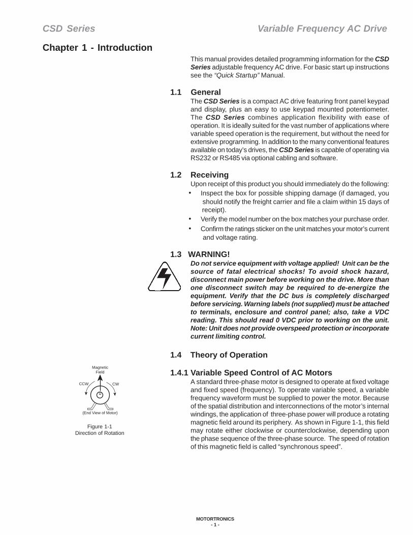
1.4.1 Variable Speed Control of AC MotorsA standard three-phase motor is designed to operate at fixed voltageand fixed speed (frequency). To operate variable speed, a variablefrequency waveform must be supplied to power the motor. Becauseof the spatial distribution and interconnections of the motor’s internalwindings, the application of three-phase power will produce a rotatingmagnetic field around its periphery. As shown in Figure 1-1, this fieldmay rotate either clockwise or counterclockwise, depending uponthe phase sequence of the three-phase source. The speed of rotationof this magnetic field is called “synchronous speed”.
Figure 1-1Direction of Rotation
MagneticField
CWCCW
(End View of Motor)

CSD Series Variable Frequency AC Drive
MOTORTRONICS- 2 -
This speed is described by this simple formula:
Where:• Synchronous speed is in RPMs (Revolutions Per Minute)• Poles are the number of poles built into the motor.• Frequency is the applied frequency of the power fed to the motor.
As you can see, synchronous speed is directly proportional to theapplied frequency. By increasing or decreasing this frequency, youcan increase or decrease the rotational speed of the magnetic field.This is the underlying theory behind the operation of the adjustablefrequency drives.
Changing the speed is only half the problem. The motor was designedto run at a fixed operation point as shown in the nameplate (frequencyvoltage). This point can be described by a “volts per hertz” (V/Hz)ratio which relates to the strength of the magnetic field. To maintainconstant field strength and constant torque, we must maintain thisratio. Since we vary the frequency to change the synchronous speed,we must simultaneously change the applied voltage to maintain thenecessary V/Hz ratio. As an example: For a constant torqueapplication, if the frequency is cut in half, the voltage must also becut in half as shown in Figure 1 - 2.
The final concept to be introduced is known as motor “slip”. Theactual torque output by an induction motor is proportional to the productof the V/Hz ratio and the slip. Slip is simply defined as the differencebetween synchronous speed and the actual motor shaft speed. Withconstant V/Hz excitation, the motor must slip to produce more torque.The greater the torque requirement, the greater amount of motor slipand the slower the resultant shaft speed.
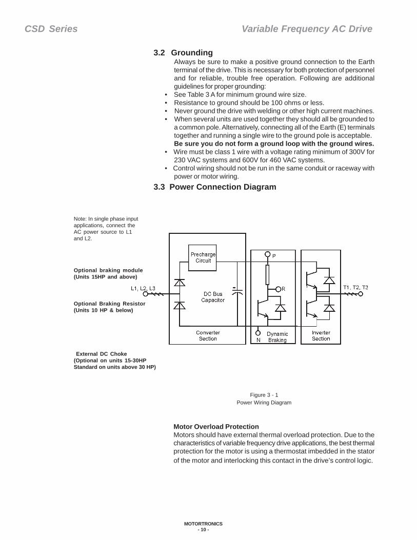
1.4.2 Drive Power SectionRefer to Figure 1 - 3. The input (converter) of the power section is athree-phase, rectifier bridge used to convert the incoming AC voltageinto DC voltage. This DC voltage is then filtered by the DC buscapacitors to produce a clean, ripple-free DC level. The converteralso includes a current limiting, pre-charge circuit. This circuit is usedto control the current inrush while the capacitors are building up theircharge when power is first applied to the drive unit. Once they arecharged, this circuit serves no further useful purpose, so it isbypassed. The output (inverter) section consists of six transistorswhich are switched by the microprocessor to produce the variablevoltage, variable frequency output waveform necessary to controlthe V/HZ ratio as discussed in the previous section. The result of thisswitching is a “chopped up square wave” voltage that produces anearly sinusoidal motor current waveform.Note: The shape of the voltage waveform prohibits accuratemeasurement with most types of voltmeters. The most accuratemeasurement is obtained by using a “rectifier” type AC voltmeter. Ifthis type of meter is unavailable, use an analog meter and check toinsure the three-phase output voltage is balanced (this shows alltransistors are switching evenly, even if the actual voltage reading ismeaningless).
Figure 1 - 2Volts per Hertz Ratio
Figure 1 - 3Power Section Block Diagram
Synchronous Speed = 120 x Frequency# of Poles
Operating Point
Frequency
Voltage
460 V
230 V
30 Hz 60 Hz

CSD Series Variable Frequency AC Drive
MOTORTRONICS- 3 -
The CSD Series unit offers an optional function called dynamic braking.Dynamic braking, in adjustable frequency drives, allows the motor toproduce 100% braking torque for a 10% duty cycle for four-quadrantoperation (like DC regenerative drives). With dynamic braking, theregenerative energy from the motor is dissipated by switching thedynamic braking transistor to shunt the regenerative current from theDC bus capacitors through the braking resistor (See Figure 1 - 3).This circuit is optional in the CSD drive line, please contact the factoryif your application requires dynamic braking.
1.4.3 Logic SectionThe heart of the drive’s control section is the Central Processing Unit(CPU). This component handles the logic functions, including outputwaveform generation, monitoring of commands, and self-diagnostics.The CPU also simplifies troubleshooting and setup by displaying andstoring very specific, alpha-numeric fault codes displayed on thekeypad. For example, you can immediately determine if an overcurrent(OC) trip occurred during start, acceleration, deceleration or constantspeed operation by the unique fault code corresponding to each ofthese conditions.The output waveform is “sine-coded, Pulse Width Modulation (PWM)”,which gained wide acceptance because of its high starting torque andsmooth low speed motor rotation capabilities. In addition, the motor’s“torque per amp” ratio is good, implying a very efficient output currentwaveform. The drive can accept control commands (run or frequencyreference inputs) from either the terminal strip or the integral keypad.The terminal frequency reference command can be either 0-10 VDC,0-5 VDC or 4-20 mA. The drive’s actual output frequency can bemonitored directly from the keypad or from a remote meter connectedto the drive’s analog meter output (0-10VDC, current regulated).
1.4.4 Motor Rating for Variable Speed ApplicationMotortronics recommends, whenever possible, the use of “drive duty”motors to prevent premature motor failures that may occur in somevariable frequency drive applications. “Drive duty” motors have increasedinsulation on the first few turns of the motor, preventing failures from“punch through” of the insulation in 400-600 volt class, low horsepowermotors. “Punch through” is caused by a proportionally higher amountof the dv/dt output of the drive being dropped across the first few turnsof the motor. “Drive duty” motors also provide rated cooling during allspeed ratings. This feature prevents failure due to reduced coolingcapabilities when a TEFC (totally enclosed fan cooled) motor is beingrun at reduced speed and in constant torque applications. Motortronicsrecommends that the motor manufacturer be consulted in all variablefrequency drive applications to ensure that the motor will be able toperform the application requirements.

CSD Series Variable Frequency AC Drive
MOTORTRONICS- 4 -
Figure 2 - 1Location and Positioning
Table 2 A - Drive Heat Loss
Chapter 2 - Installation
2.1 LocationProper location of the CSD Series is necessary to achieve specifiedperformance and normal lifetime operation. The CSD Series shouldalways be installed in an area where the following conditions exist:• Ambient operating temperature:
Enclosed unit: -10 to 40° C (14 to 104° F).Chassis unit: -10 to 50° C (14 to 122° F).
• Protected from rain and moisture• Shielded from direct sunshine• Free from metallic particles and corrosive gas.
Make sure there is sufficient clearance around the CSD Series unit forcooling, wiring and maintenance purposes. To maximize the effectiveair flow (and cooling), the inverter should be installed with its heatsinkribs oriented vertically. We also recommend you remove the front coverif possible when you mount the inverter inside a larger enclosure. Thiswill further improve the air flow over the electronic components andimprove the unit’s reliability. (Fig. 2 - 1). Refer to the chart below formodel heat dissipation requirements when installing your unit.
Model Number
Drive(HP)
DriveEfficiency
(%)
Rated Current(Amps)
Drive Loss (W)
Min. Req.Air Vol.(CFM)
Min. Sfc. Area.Steel Box(Sq. Ft)
Min. Sfc. AreaFiberglass Box
(Sq. Ft)CSD-2P5 0.5 95.56 3.1 23.25 4.04 4.65 7.27CSD-201 1 96.74 4.5 33.75 5.87 6.75 10.55CSD-202 2 97.26 7.5 56.25 9.78 11.25 17.58CSD-203 3 97.44 10.5 78.75 13.70 15.75 24.61CSD-205 5 97.44 17.5 131.25 22.83 26.25 41.02CSD-207 7.5 97.47 26 195.00 33.91 39.00 60.94CSD-210 10 97.44 35 262.50 45.65 52.50 82.03CSD-215 15 97.61 49 367.50 63.91 73.50 114.84CSD-220 20 97.66 64 480.00 83.48 96.00 150.00CSD-230 30 97.87 87 652.50 113.48 130.50 203.91CSD-401 1 97.64 2.3 24.15 4.20 4.83 7.55CSD-402 2 98.04 3.8 39.90 6.94 7.98 12.47CSD-403 3 98.21 5.2 54.60 9.50 10.92 17.06CSD-405 5 98.19 8.8 92.40 16.07 18.48 28.88CSD-407 7.5 98.21 13 136.50 23.74 27.30 42.66CSD-410 10 98.20 17.5 183.75 31.96 36.75 57.42CSD-415 15 98.28 25 262.50 45.65 52.50 82.03CSD-420 20 98.35 32 336.00 58.43 67.20 105.00CSD-430 30 98.35 48 504.00 87.65 100.80 157.50
CSD Series Variable Frequency AC Drive
MOTORTRONICS- 5 -
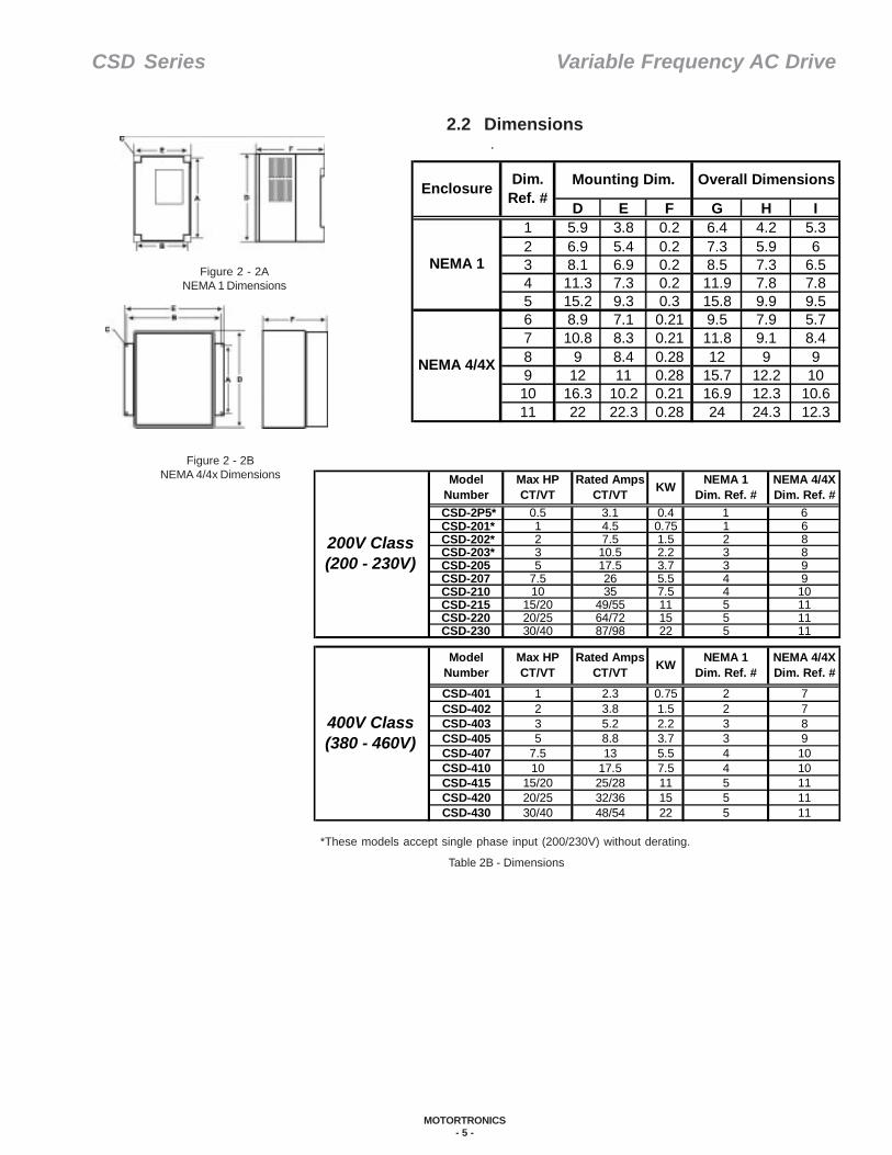
2.2 Dimensions.
*These models accept single phase input (200/230V) without derating.
Figure 2 - 2ANEMA 1 Dimensions
Figure 2 - 2BNEMA 4/4x Dimensions
Table 2B - Dimensions
CSD-2P5* 0.5 3.1 0.4 1 6CSD-201* 1 4.5 0.75 1 6CSD-202* 2 7.5 1.5 2 8CSD-203* 3 10.5 2.2 3 8CSD-205 5 17.5 3.7 3 9CSD-207 7.5 26 5.5 4 9CSD-210 10 35 7.5 4 10CSD-215 15/20 49/55 11 5 11CSD-220 20/25 64/72 15 5 11CSD-230 30/40 87/98 22 5 11
CSD-401 1 2.3 0.75 2 7CSD-402 2 3.8 1.5 2 7CSD-403 3 5.2 2.2 3 8CSD-405 5 8.8 3.7 3 9CSD-407 7.5 13 5.5 4 10CSD-410 10 17.5 7.5 4 10CSD-415 15/20 25/28 11 5 11CSD-420 20/25 32/36 15 5 11CSD-430 30/40 48/54 22 5 11
KW NEMA 1Dim. Ref. #
NEMA 4/4XDim. Ref. #
400V Class (380 - 460V)
ModelNumber
Max HPCT/VT
Rated AmpsCT/VT KW NEMA 1
Dim. Ref. #NEMA 4/4XDim. Ref. #
200V Class (200 - 230V)
ModelNumber
Max HPCT/VT
Rated AmpsCT/VT
D E F G H I1 5.9 3.8 0.2 6.4 4.2 5.32 6.9 5.4 0.2 7.3 5.9 63 8.1 6.9 0.2 8.5 7.3 6.54 11.3 7.3 0.2 11.9 7.8 7.85 15.2 9.3 0.3 15.8 9.9 9.56 8.9 7.1 0.21 9.5 7.9 5.77 10.8 8.3 0.21 11.8 9.1 8.48 9 8.4 0.28 12 9 99 12 11 0.28 15.7 12.2 1010 16.3 10.2 0.21 16.9 12.3 10.611 22 22.3 0.28 24 24.3 12.3
NEMA 1
NEMA 4/4X
Enclosure Dim.Ref. #
Mounting Dim. Overall Dimensions
CSD Series Variable Frequency AC Drive
MOTORTRONICS- 6 -
2.3 Specifications
Table 2 C - Specifications
* These models accept single phase input (200-230V) without derating.
Model HPRatedMotor (KW)
Rated Current
(A)
Rated Output (KVA)
InputVoltage
OutputVoltage
CSD-2P5* 0.5 0.4 3.1 1.2CSD-201* 1 0.75 4.5 1.7CSD-202* 2 1.5 7.5 2.9CSD-203* 3 2.2 10.5 4.0CSD-205 5 3.7 17.5 6.7CSD-207 7.5 5.5 26 9.9CSD-210 10 7.5 35 13.3CSD-215 15 11 49 18.7CSD-220 20 15 64 24.4CSD-230 30 22 87 33.2CSD-401 1 .75 2.3 1.7CSD-402 2 1.5 3.8 2.9CSD-403 3 2.2 5.2 4.0CSD-405 5 3.7 8.8 6.7CSD-407 7.5 5.5 13 9.9CSD-410 10 7.5 17.5 13.3CSD-415 15 11 25 19.1CSD-420 20 15 32 24.4CSD-430 30 22 48 36.6
1 or 3 Phase
200-230V+10%
50/60 Hz+5%
3 Phase380-460V
+10%50/60 Hz
+5%
3 Phase200-230V
3 Phase380-460V

CSD Series Variable Frequency AC Drive
MOTORTRONICS- 7 -
1 - 12 KHz0.1 - 400 HzDigital: 0.01%Analog: 0.4% 0.01 HZ with computer of PLC control, 0.1 Hz with keypad control with frequency above 100 Hz0 - 5, 0 - 10V, 4 - 20mA, 10K PotentiometerOptional card: Bi-polar ± 5 or ±10 Vdc command available. (Specify bi-polar command signal range)Programmable between 30% - 200%2 separate programmable ACCEL/DECEL times0.1 - 3600 SEC with 2 S-curvesProgrammable DECEL or free run to stop150% for up to 1 minute
Braking Torque 200V & 400V Class
Standard braking torque = 20%100% braking torque available with addition of optional resistors (plus braking transistors on units rated 15HP and above)18 patterns, one curve programmableIGBT transistors in a sine-coded PWM (Pulse Width Modulated) firing schemeApproximately 200% of unit rated current150% for 1 minuteProgrammable electronic thermal overload relay200V Class: DC bus exceeds 427V400V Class: DC bus exceeds 854V200V Class: DC bus voltage drop < 200V 400V Class: DC bus voltage drop < 400VProgrammable 0~2 seconds: unit can be restarted via speed searchMotor coast to stop at blown fuseProtected by thermister/thermostatVia charge LED
Start -up Standard on all unitsRunning Standard on all units Operation Signal Forward/Reverse operation; individual command
MultifunctionInput Selection
Standard: 3 dry contact inputs onlyOptional: 120 Vac interface card
MultifunctionOutput 1 output 35Vdc, 50mA maximum
Fault Output 250 Vac 1A, 30 Vdc 1A maximum
Frequency reference bias/gain, upper lower limit, auto/manual torque boos, frequency meter gain calibration, auto reset attempt, skip frequency, S-curve: ACCEL/DECEL, current limit, carrier frequency adjust (1 - 12 KHz), communication link function, energy saver, vibration control, 7 process timers
Frequency command, output frequency, output current, output voltage, P-N bus voltage, rotation direction, engineering units
Analog output (0-10V), possible to select output frequency, setting frequency, output voltage and P-N bus voltageNEMA 1 (IP20) standard, NEMA 4 /4X also available (up to 10HP)Indoor (protected from gas and dust) 3,300 feet (without derating). Use in an enclosure with filtered forced ventilation, or if standalone, in a clean pollution-free environmentEnclosed: -10º C to 40º C (14º F to 104º F)Chassis: -10º C to 50º C (14º F to 122º F)-10º C to 50º C (14º F to 122º F)0 - 95% non-condensing0.5GEMC 89/336/EEC
App
rova
ls
UL listed and Canadian UL (cUL) listed, CE Approved
EMC
Envi
ronm
enta
lC
ondi
tions
Instantaneous OvercurrentOverload Capacity of Drive
Output Signal
Enclosure
Humidity
Digital Operator Monitor
Built-in Functions
DC Bus Protection
Power Charge Indication
Vibration
Output Power CircuitV/f Pattern
Overvoltage
Storage Temperature
Input Signal
Analog Output Monitor
Location and Altitude
Ambient Temperature
Momentary Power Loss
Ope
ratio
n C
ondi
tions
Frequency Control Range
Frequency Accuracy
Frequency Resolution
Motor Overload Protection
Frequency Setting Signal
ACCEL/DECEL Time
Undervoltage
Heat Sink Fin Overheat
Ground Fault Protection
Con
trol
Cha
ract
eris
tics
Prot
ectio
n Fu
nctio
ns
Carrier Frequency
Stall Prevention
Starting Torque

CSD Series Variable Frequency AC Drive
MOTORTRONICS- 8 -
This chapter deals with the recommended wiring practices for the CSDSeries adjustable frequency drive. Please remember, you must alwaysconform to the National Electrical Code (NEC) and any applicable localcodes. Always make sure the keypad display is off, that the red ChargeLED (LED 101) on the PC board is off, and the DC bus is dischargedbefore adding or changing any wiring!
WARNING!This section involves working with potentially lethal voltage levels!Caution must be used to prevent personal harm.
3.1 Main Power WiringMain power wiring precautions:Remember, the following wiring guidelines are only suggestions. Youmust always conform to the NEC and your locally accepted wiringpractices.
Table 3 A - Suggested Power Circuit Wiring and Components
Note 1: See NEC article 430 and NEC article 310 for sizing or branch circuit conductors.Note 2: See NEC article 430 part D for motor branch circuit, short circuit and ground
fault protection sizing.Note 3: See NEC article 250 for sizing of ground conductors.
Chapter 3 - Wiring
Model Min. Power Wire Size
Max. Non-Delay Fuse
(2)
Max. Delay Fuse (2)
Max. Delay Circuit
Breaker (2)
Min. Ground
Wire SizeCSD-2P5CSD-201CSD-202 15 A 15 A 15 ACSD-203CSD-205CSD-207 10 AWG 30 A 30 A 30 A 10 AWGCSD-210 8 AWG 80 A 50 A 70 A 8 AWGCSD-215 6 AWG 125 A 70 A 100 ACSD-220 4 AWG 150 A 80 A 125 ACSD-230 2 AWG 225 A 125 A 200 A 4 AWGCSD-401CSD-402CSD-403CSD-405CSD-407CSD-410CSD-415 10 AWG 30 A 30 A 30 A 10 AWGCSD-420 8 AWG 80 A 50 A 70 A 8 AWGCSD-430 6 AWG 125 A 70 A 100 A 6 AWG
12 AWG
14 AWG
12 AWG
6 AWG
14 AWG
20 A
10 A
20 A
10 A
15 A
20 A
10 A
20 A
10 A
20 A
10 A
15 A
20A12 AWG
10 A
15 A
14 AWG
12 AWG
14 AWG

CSD Series Variable Frequency AC Drive
MOTORTRONICS- 9 -
• NEVER CONNECT THE INPUT POWER WIRING TO DRIVE OUTPUTTERMINALS T1, T2, T3. IF YOU DO, THE UNIT WILL BE DAMAGED.
• DO NOT touch any circuit components while AC power is on orimmediately after the main AC power is disconnected from theunit. You MUST wait for the LED on the control board toextinguish.
• DO NOT make any interconnection to the circuit before unit isdisconnected from the AC power line and the power LED on theunit is extinguished. Failure to adhere to this warning couldresult in serious or lethal injury.
• This unit is only intended for use in pollution degree 2 macro-environment or equivalent.
• Never use a MEGGER to check the motor wires while the drive isconnected. The semiconductor output module will be destroyed by thehigh transient voltage.
• If the source feeding the drive is greater than 500 KVA you shouldinstall a three-phase, AC input line reactor to prevent possible damageto the input rectifier bridge (3% impedance, minimum).
• If the input voltage imbalance is greater than 2%, you should alsoapply an AC input line reactor (3% impedance, minimum).
• If you are using a single-phase input supply, be sure to connect theincoming power to terminals L1 and L2 of the drive.
• Make sure there are no power factor correction capacitors connecteddirectly to the input or on the output leads of the drive.
• To comply with NEC requirements for branch circuit protection youmay need an externally fused disconnect.
• Recommended values for input wiring are also given in Table 3 A. For230 V units be sure to use wire rated for 300 volts; for 460 V.
• Always use UL/CSA approved wire and listed field wiring lug kits orlisted ring terminals.
• Physically separate power and control wiring. If they must cross, doso at 90 degree angles.
• Never install Start/Stop Magnetic Contactor (MC) between drive outputterminals and motor. The transient de-energizing surge of the magneticcontactor will destroy the unit or cause the drive to trip.
• Never use a Start/Stop Magnetic Contactor (MC) on the line side of thedrive to Start/Stop the drive.
• Use shielded cable for all control wiring connections to the TM2 terminalblock. Ground the shield at the other end of the cable (not to thedrive).
• Use copper conductors only, size field wiring based on 75° C wireonly.
• Follow the Table 3 B for suitable supply circuits on specific drives.(Information based on UL 508 table 47.2, February 23, 1993.)
Table 3 B - Suitable Supply Circuits
Model Max VoltageMax Supply Short
Circuit Rating(Symmetrical Amperes)
CSD-2P5 to CSD-201 230V 1000
CSD-202 to 230 230V 5000
CSD-401 460V 1000
CSD-402 to 430 460V 5000
CSD Series Variable Frequency AC Drive
MOTORTRONICS- 10 -
3.2 GroundingAlways be sure to make a positive ground connection to the Earthterminal of the drive. This is necessary for both protection of personneland for reliable, trouble free operation. Following are additionalguidelines for proper grounding:
• See Table 3 A for minimum ground wire size.• Resistance to ground should be 100 ohms or less.• Never ground the drive with welding or other high current machines.• When several units are used together they should all be grounded to
a common pole. Alternatively, connecting all of the Earth (E) terminalstogether and running a single wire to the ground pole is acceptable.Be sure you do not form a ground loop with the ground wires.
• Wire must be class 1 wire with a voltage rating minimum of 300V for230 VAC systems and 600V for 460 VAC systems.
• Control wiring should not be run in the same conduit or raceway withpower or motor wiring.
3.3 Power Connection Diagram
Figure 3 - 1Power Wiring Diagram
Motor Overload ProtectionMotors should have external thermal overload protection. Due to thecharacteristics of variable frequency drive applications, the best thermalprotection for the motor is using a thermostat imbedded in the statorof the motor and interlocking this contact in the drive’s control logic.
Optional braking module(Units 15HP and above)
Optional Braking Resistor(Units 10 HP & below)
Note: In single phase inputapplications, connect theAC power source to L1and L2.
External DC Choke(Optional on units 15-30HPStandard on units above 30 HP)
CSD Series Variable Frequency AC Drive
MOTORTRONICS- 11 -
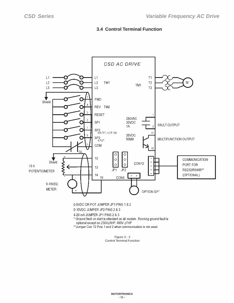
Figure 3 - 2Control Terminal Function
3.4 Control Terminal Function
CSD Series Variable Frequency AC Drive
MOTORTRONICS- 12 -
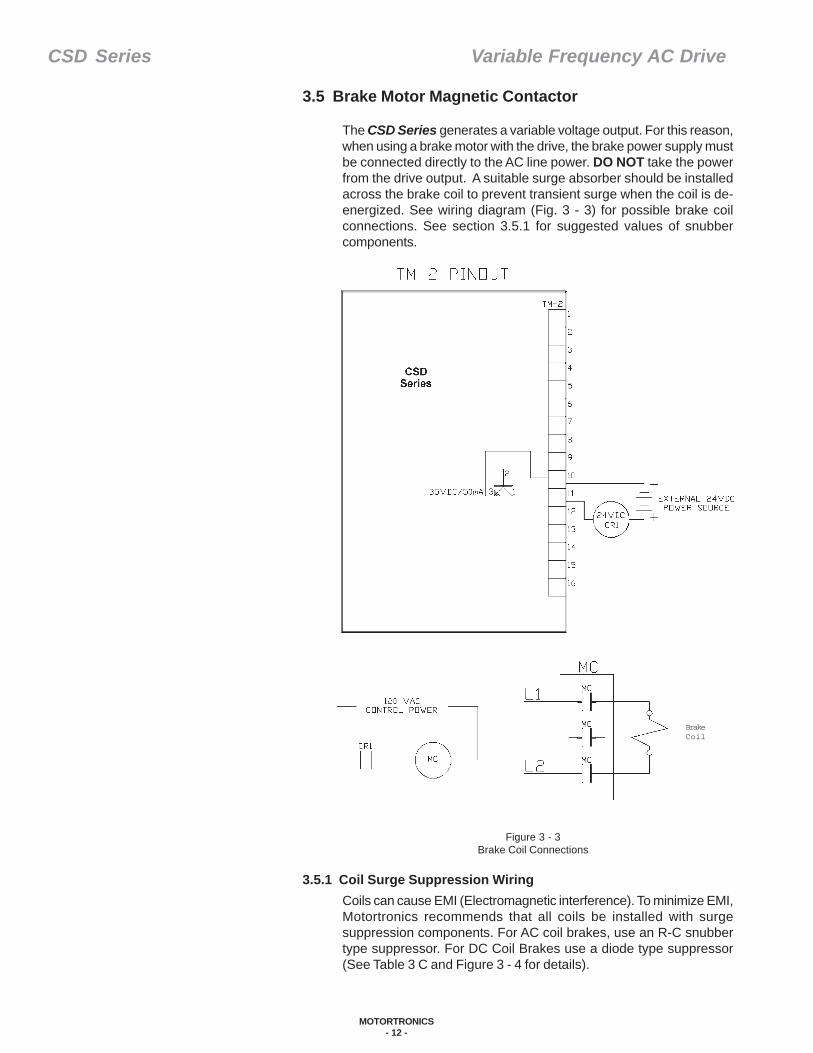
3.5 Brake Motor Magnetic Contactor
The CSD Series generates a variable voltage output. For this reason,when using a brake motor with the drive, the brake power supply mustbe connected directly to the AC line power. DO NOT take the powerfrom the drive output. A suitable surge absorber should be installedacross the brake coil to prevent transient surge when the coil is de-energized. See wiring diagram (Fig. 3 - 3) for possible brake coilconnections. See section 3.5.1 for suggested values of snubbercomponents.
Figure 3 - 3Brake Coil Connections
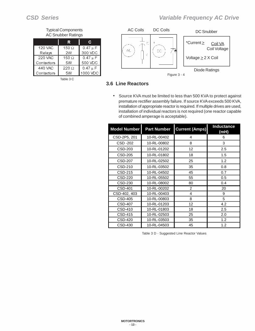
BrakeCoil
Coils can cause EMI (Electromagnetic interference). To minimize EMI,Motortronics recommends that all coils be installed with surgesuppression components. For AC coil brakes, use an R-C snubbertype suppressor. For DC Coil Brakes use a diode type suppressor(See Table 3 C and Figure 3 - 4 for details).
3.5.1 Coil Surge Suppression Wiring
CSD Series Variable Frequency AC Drive
MOTORTRONICS- 13 -
Diode Ratings
AC Coils DC Coils
**Current >
Voltage > 2 X Coil
Coil VACoil Voltage
DC Snubber
Figure 3 - 4
Typical ComponentsAC Snubber Ratings
Table 3 C3.6 Line Reactors
• Source KVA must be limited to less than 500 KVA to protect againstpremature rectifier assembly failure. If source KVA exceeds 500 KVA,installation of appropriate reactor is required. If multiple drives are used,installation of individual reactors is not required (one reactor capableof combined amperage is acceptable).
Table 3 D - Suggested Line Reactor Values
Model Number Part Number Current (Amps) Inductance (mH)
CSD-2P5, 201 10-RL-00402 4 6CSD -202 10-RL-00802 8 3CSD-203 10-RL-01202 12 2.5CSD-205 10-RL-01802 18 1.5CSD-207 10-RL-02502 25 1.2CSD-210 10-RL-03502 35 0.8CSD-215 10-RL-04502 45 0.7CSD-220 10-RL-05502 55 0.5CSD-230 10-RL-08002 80 0.4CSD-401 10-RL-00202 2 20
CSD-402, 403 10-RL-00403 4 9CSD-405 10-RL-00803 8 5CSD-407 10-RL-01203 12 4.2CSD-410 10-RL-01803 18 2.5CSD-415 10-RL-02503 25 2.0CSD-420 10-RL-03503 35 1.2CSD-430 10-RL-04503 45 1.2
CSD Series Variable Frequency AC Drive
MOTORTRONICS- 14 -
3.6.1 Initial Power Up
• For initial test run procedure, see Chapter 7.• For initial start-up procedure, see Chapter 6.
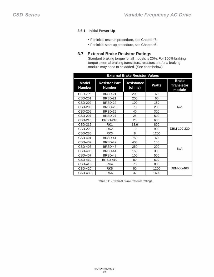
3.7 External Brake Resistor RatingsStandard braking torque for all models is 20%. For 100% brakingtorque external braking transistors, resistors and/or a brakingmodule may need to be added. (See chart below)
Table 3 E - External Brake Resistor Ratings
Model Number
Resistor Part Number
Resistance(ohms) Watts
Brake Transistor
moduleCSD-2P5 BRSD-21 200 60CSD-201 BRSD-21 200 60CSD-202 BRSD-22 100 150CSD-203 BRSD-23 70 200CSD-205 BRSD-25 40 300CSD-207 BRSD-27 25 500CSD-210 BRSD-210 20 600CSD-215 RK1 13.6 800CSD-220 RK2 10 900CSD-230 RK3 8 1200CSD-401 BRSD-41 750 60CSD-402 BRSD-42 400 150CSD-403 BRSD-43 250 200CSD-405 BRSD-44 150 300CSD-407 BRSD-48 100 500CSD-410 BRSD-410 80 600CSD-415 RK4 75 800CSD-420 RK5 50 1200CSD-430 RK6 32 1600
External Brake Resistor Values
N/A
DBM-100-230
N/A
DBM-50-460

CSD Series Variable Frequency AC Drive
MOTORTRONICS- 15 -
3.8 Power Terminal Block (TM1) DescriptionThe control part of the CSD Series drive is the TM1 or Power TerminalBlock (the large terminal block on the bottom PC board). Listed inTable 3 F are the function descriptions of TM1. The symbols inparentheses are the European equivalent codes.
Table 3 F - TM1 Descriptions
Table 3 G - TM1 Layout
Figure 3 - 5TM1 Terminal Block
See Table 3 G for the terminal block configuration in your unit.
1.
2.
3.
4.
Table 3 H - TM Torque Specs
Follow the above diagram when wiring your CSD Series drive. Also:• Never connect the input power wiring to the drive terminals T1, T2, T3,
P, or R. The drive will fail.• Always use UL/CSA approved wiring and lugs.• Always make a positive ground termination to the Earth terminal of
the drive.• The P & R terminals are for resistor attachment only. If you connect
power to these points, the drive will fail.
Symbol Function DescriptionL1 (R)L2 (S)L3 (T)
N External braking unit terminalsPR
T1 (U)T2 (V)T3 (W)P1, P External DC reactor terminals
Input terminals of AC line power:Single Phase: L1/L2 (L1/L3 for CSD-230)Three Phase: L1/L2/L3
Output terminals
External braking resistor terminals
Model Number
TM1 Layout
CSD-2P5CSD-201CSD-202CSD-203CSD-205CSD-207CSD-210CSD-215 2CSD-220 3CSD-230 4CSD-401CSD-402CSD-403CSD-405CSD-407CSD-410CSD-415CSD-420CSD-430
1
1
3
Model #TM1
TorqueSpecs
TM2Torque Specs
CSD-2P5CSD-201CSD-202 16 LB-IN
CSD-203CSD-205CSD-207CSD-210CSD-215CSD-220CSD-230CSD-401CSD-402CSD-403CSD-405CSD-407CSD-410CSD-415CSD-420CSD-430
12 LB-IN
13.8 LB-IN
13.8 LB-IN
22.1 LB-IN
22.1 LB-IN
16 LB-IN
7 LB-IN

CSD Series Variable Frequency AC Drive
MOTORTRONICS- 16 -
This section reviews the external controls and the speed potentiometeron the keypad. If you are using the keypad (without the speedpotentiometer) you do not need to review this section.
4.1 Control Terminal Block (TM2) Function DescriptionThe control terminal block (TM2) is the block on the top PC board.The following diagram illustrates the physical representation of theterminal block (TM2) and the available connections when you openthe cover of the CSD enclosure. Connections 3-9 are dry contactsonly. Dry contact control wire connections must be less than 10 feetin length. Motortronics recommends using shielded cable or twistedpairs. Note TM2 torque specs is 7IN-LB.
As you finish each connection, complete the accompanyingprogramming. Carefully review all diagrams and programming detailsso the connections are made correctly.
1 TRIP 2RELAY
3FWD
4REV
5COM
6SP1
7SP2
8SP3
9RESET
10SYN-
11SYN+
12 13 14 FM-
15FM++ -
Control Connections Terminal (TM2)
Figure 4 - 1TM2 Terminal Block
Wiring of control circuits (TM2) andpower circuits (TM1) must comply withthe separation of circuits requirementsso that there is a physical spacingbetween conductors of different circuits.The class 2 circuits and limited voltage/current circuits of TM2 are to beconnected with wires suitable forconnection to the class 1 circuits or linevoltage terminals of TM1. Use the twolower holes in the end plate for wiring tothe class 1 circuits of TM1. Use aseparate hole in the end plate for wiringto the class 2 circuit of TM2.
Table 4 A - Terminal TM2 Connection Descriptions
Chapter 4 - Remote Control
CSD Series Variable Frequency AC Drive
MOTORTRONICS- 17 -
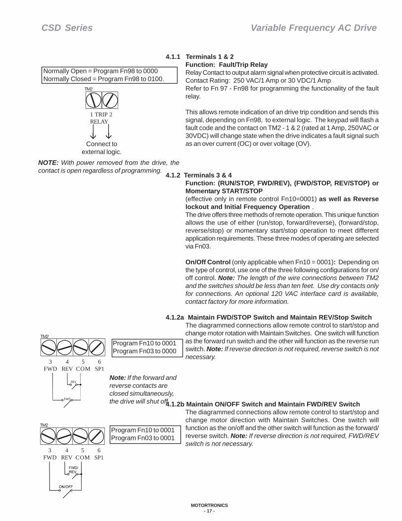
4.1.1 Terminals 1 & 2Function: Fault/Trip RelayRelay Contact to output alarm signal when protective circuit is activated.Contact Rating: 250 VAC/1 Amp or 30 VDC/1 AmpRefer to Fn 97 - Fn98 for programming the functionality of the faultrelay.
This allows remote indication of an drive trip condition and sends thissignal, depending on Fn98, to external logic. The keypad will flash afault code and the contact on TM2 - 1 & 2 (rated at 1 Amp, 250VAC or30VDC) will change state when the drive indicates a fault signal suchas an over current (OC) or over voltage (OV).
4.1.2 Terminals 3 & 4Function: (RUN/STOP, FWD/REV), (FWD/STOP, REV/STOP) orMomentary START/STOP(effective only in remote control Fn10=0001) as well as Reverselockout and Initial Frequency Operation .The drive offers three methods of remote operation. This unique functionallows the use of either (run/stop, forward/reverse), (forward/stop,reverse/stop) or momentary start/stop operation to meet differentapplication requirements. These three modes of operating are selectedvia Fn03.
On/Off Control (only applicable when Fn10 = 0001): Depending onthe type of control, use one of the three following configurations for on/off control. Note: The length of the wire connections between TM2and the switches should be less than ten feet. Use dry contacts onlyfor connections. An optional 120 VAC interface card is available,contact factory for more information.
4.1.2a Maintain FWD/STOP Switch and Maintain REV/Stop SwitchThe diagrammed connections allow remote control to start/stop andchange motor rotation with Maintain Switches. One switch will functionas the forward run switch and the other will function as the reverse runswitch. Note: If reverse direction is not required, reverse switch is notnecessary.
4.1.2b Maintain ON/OFF Switch and Maintain FWD/REV SwitchThe diagrammed connections allow remote control to start/stop andchange motor direction with Maintain Switches. One switch willfunction as the on/off and the other switch will function as the forward/reverse switch. Note: If reverse direction is not required, FWD/REVswitch is not necessary.
Normally Open = Program Fn98 to 0000 Normally Closed = Program Fn98 to 0100.
1 TRIP 2RELAY
TM2
Connect toexternal logic.
NOTE: With power removed from the drive, thecontact is open regardless of programming.
Program Fn10 to 0001Program Fn03 to 0000
TM2
3FWD
4REV
5COM
6SP1
Note: If the forward andreverse contacts areclosed simultaneously,the drive will shut off.
Program Fn10 to 0001Program Fn03 to 0001
TM2
3FWD
4REV
5COM
6SP1
CSD Series Variable Frequency AC Drive
MOTORTRONICS- 18 -
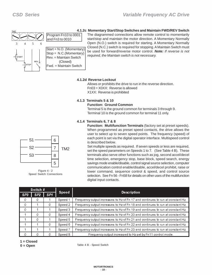
4.1.2c Momentary Start/Stop Switches and Maintain FWD/REV SwitchThe diagrammed connections allow remote control to momentarilystart/stop and maintain the motor direction. A Momentary NormallyOpen (N.O.) switch is required for starting. A Momentary NormallyClosed (N.C.) switch is required for stopping. A Maintain Switch mustbe used for forward/reverse motor control. Note: If reverse is notrequired, the Maintain switch is not necessary.
4.1.2d Reverse LockoutAllows or prohibits the drive to run in the reverse direction.Fn03 = X0XX: Reverse is allowedX1XX: Reverse is prohibited
4.1.3 Terminals 5 & 10Function: Ground CommonTerminal 5 is the ground common for terminals 3 through 9.Terminal 10 is the ground common for terminal 11 only.
4.1.4 Terminals 6, 7 & 8Function: Multifunction Terminals (factory set at preset speeds).When programmed as preset speed contacts, the drive allows theuser to select up to seven speed points. The frequency (speed) ofeach point is set via the digital operator interface. Multispeed controlis described below.Set multiple speeds as required. If seven speeds or less are required,set the speed parameters on Speeds 1 to 7. (See Table 4 B). Theseterminals also serve other functions such as jog, second accel/deceltime selection, emergency stop, base block, speed search, energysavings mode enable/disable, control signal source selection, computercommunication control enable/disable, accel/decel prohibit, raise orlower command, sequence control & speed, and control sourceselection. See Fn 56 - Fn58 for details on other uses of the multifunctiondigital input contacts.
Table 4 B - Speed Switch 1 = Closed 0 = Open
Program Fn10 to 0001and Fn3 to 0010
Start = N.O. (Momentary)Stop = N.C.(Momentary)Rev. = Maintain Switch
(Closed)Fwd. = Maintain Switch
TM2
3 4 5 6
Figure 4 - 2Speed Switch Connections
6
7
8
5
S1
S2
S3TM2
CSD Series Variable Frequency AC Drive
MOTORTRONICS- 19 -
4.1.6 Terminal 9Function: ResetThe drive can be reset from fault condition by connecting terminal 9to ground common (terminal 5). Reset is effective in both remotecontrol (Fn10=1) and digital operation control (Fn10=0).
4.1.7 Terminal 14Function: Common for terminals 12, 13 & 15.Negative terminal of 10K ohm frequency command potentiometer orpositive terminal of 0-10V, 0-5V, 4-20 mA analog signal commandnegative terminal. Also, negative terminal for frequency meterconnected to Pin 15.
4.1.8 Terminals 12 & 13Function: Remote Frequency CommandTerminal 12: Positive terminal of 10K ohm frequency commandpotentiometer.Terminal 13: Wiper of 10K ohm frequency command potentiometeror 0-10V, 0-5V, 4-20mA analog signal command positive terminal.
4.1.9 Terminal 15Function: Remote Frequency Meter DrivePositive terminal of full scale moving coil 10VDC frequency meter at1mA maximum.
4.1.5 Terminal 11Function: Multifunction Output (Contact rated for 50mA at 35VDCmaximum)This terminal is used for the drive’s programmable function, open-collector output. This output can serve any of three purposes,depending upon the value programmed into Fn61:Fn61 = 00 - 05: transistor is normally off.06 - 11: transistor is normally on.
a. 00/06: “Run” mode output. The open collector transistor will be turnedon (terminal #11 pulled low) while the drive is running.
b. 01/07: Up to desired frequency mode output. The transistor is turnedon, pulling terminal #11 low while the output frequency matches thefrequency reference command.
c. 02/08: ”Bandwidth” mode output. The transistor is turned on when theoutput frequency is in agreement with the value programmed in Fn08+ the value programmed in Fn09.
d. 03/09: Frequency detection greater than mode output. The transistoris turned on when output frequency>than the value programmed intoFn08.
e. 04/10: Frequency detection less than mode output. The transistor isturned on when the output frequency is < the value programmed intoFn08.
f. 05/11: Over torque detection mode output. The transistor is turned onwhen the drive detects an over torque condition.
CSD Series Variable Frequency AC Drive
MOTORTRONICS- 20 -
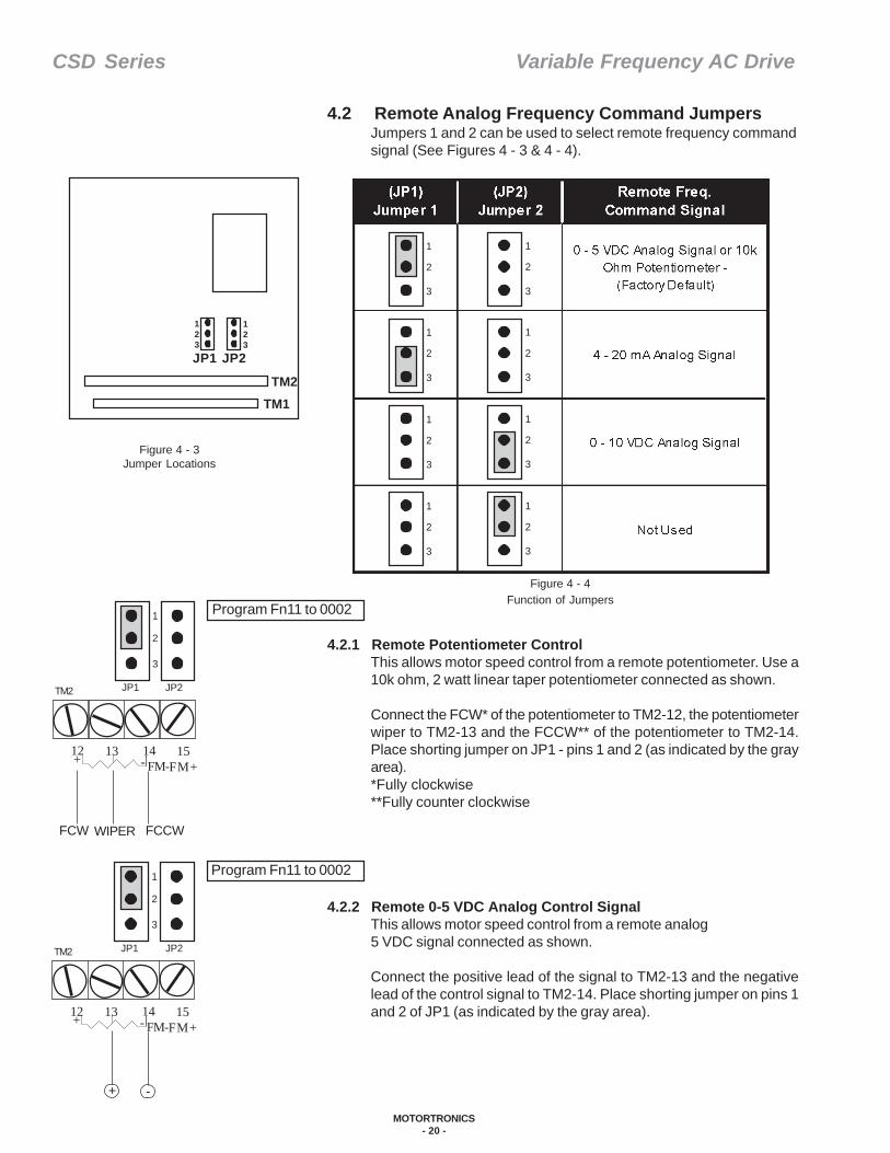
Program Fn11 to 0002
JP1 JP2
1
2
3
12 13 14 FM-
15FM++ -
TM2
FCW FCCWWIPER
Program Fn11 to 0002
JP1 JP2
1
2
3
12 13 14 FM-
15FM++ -
TM2
+ -
1
2
3
1
2
3
1
2
3
1
2
3
1
2
3
1
2
3
1
2
3
1
2
3
Figure 4 - 4Function of Jumpers
Figure 4 - 3Jumper Locations
JP1 JP2
TM2TM1
123
123
4.2 Remote Analog Frequency Command JumpersJumpers 1 and 2 can be used to select remote frequency commandsignal (See Figures 4 - 3 & 4 - 4).
4.2.1 Remote Potentiometer ControlThis allows motor speed control from a remote potentiometer. Use a10k ohm, 2 watt linear taper potentiometer connected as shown.
Connect the FCW* of the potentiometer to TM2-12, the potentiometerwiper to TM2-13 and the FCCW** of the potentiometer to TM2-14.Place shorting jumper on JP1 - pins 1 and 2 (as indicated by the grayarea).*Fully clockwise**Fully counter clockwise
4.2.2 Remote 0-5 VDC Analog Control SignalThis allows motor speed control from a remote analog5 VDC signal connected as shown.
Connect the positive lead of the signal to TM2-13 and the negativelead of the control signal to TM2-14. Place shorting jumper on pins 1and 2 of JP1 (as indicated by the gray area).
CSD Series Variable Frequency AC Drive
MOTORTRONICS- 21 -
Program Fn11 to 0002
JP1 JP2
1
2
3
12 13 14 FM-
15FM++ -
TM2
+ -
Program Fn11 to 0002
JP1 JP2
1
2
3
12 13 14 FM-
15FM++ -
TM2
+ -
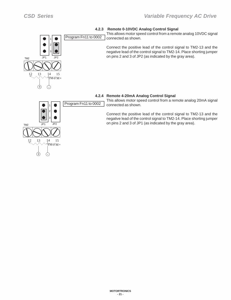
4.2.3 Remote 0-10VDC Analog Control SignalThis allows motor speed control from a remote analog 10VDC signalconnected as shown.
Connect the positive lead of the control signal to TM2-13 and thenegative lead of the control signal to TM2-14. Place shorting jumperon pins 2 and 3 of JP2 (as indicated by the gray area).
4.2.4 Remote 4-20mA Analog Control SignalThis allows motor speed control from a remote analog 20mA signalconnected as shown.
Connect the positive lead of the control signal to TM2-13 and thenegative lead of the control signal to TM2-14. Place shorting jumperon pins 2 and 3 of JP1 (as indicated by the gray area).
CSD Series Variable Frequency AC Drive
MOTORTRONICS- 22 -
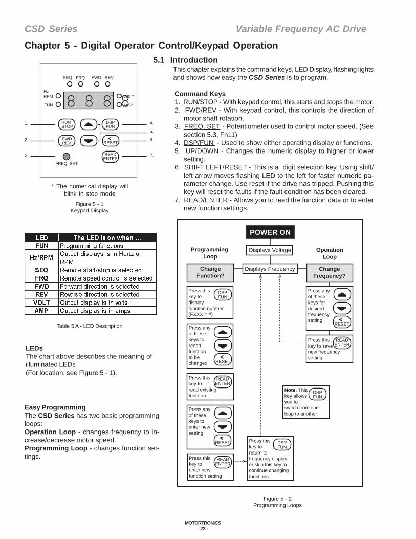
5.1 IntroductionThis chapter explains the command keys, LED Display, flashing lightsand shows how easy the CSD Series is to program.
Command Keys1. RUN/STOP - With keypad control, this starts and stops the motor.2. FWD/REV - With keypad control, this controls the direction of
motor shaft rotation.3. FREQ. SET - Potentiometer used to control motor speed. (See
section 5.3, Fn11)4. DSP/FUN - Used to show either operating display or functions.5. UP/DOWN - Changes the numeric display to higher or lower
setting.6. SHIFT LEFT/RESET - This is a digit selection key. Using shift/
left arrow moves flashing LED to the left for faster numeric pa-rameter change. Use reset if the drive has tripped. Pushing thiskey will reset the faults if the fault condition has been cleared.
7. READ/ENTER - Allows you to read the function data or to enternew function settings.
Easy ProgrammingThe CSD Series has two basic programmingloops:Operation Loop - changes frequency to in-crease/decrease motor speed.Programming Loop - changes function set-tings.
LEDsThe chart above describes the meaning ofilluminated LEDs(For location, see Figure 5 - 1).
Table 5 A - LED Description
Figure 5 - 2Programming Loops
* The numerical display willblink in stop mode
Figure 5 - 1Keypad Display
Chapter 5 - Digital Operator Control/Keypad Operation
SEQ FRQ FWD REV
HzRPM
FUN
VOLT
AMP
RUNSTOP
DSPFUN
FWDREV RESET
READENTER
FREQ. SET
1.
2.
3.
4.
6.
7.
5.
8 8 8 8*
POWER ON
Displays Voltage
Displays Frequency
Programming Loop
OperationLoop
ChangeFunction?
ChangeFrequency?
DSPFUN
RESET
Press this key to display function number(FXXX = #)
Press anyof these keys for desiredfrequencysetting
RESET
Press anyof these keys toreachfunctionto bechanged
READENTER
Press thiskey to savenew frequencysetting
READENTER
Press thiskey toread existingfunction
RESET
Press anyof these keys to enter newsetting
READENTER
Press thiskey toenter newfunction setting
DSPFUN
Press thiskey toreturn tofrequency displayor skip this key tocontinue changingfunctions
DSPFUN
Note: Thiskey allowsyou to switch from one loop to another

CSD Series Variable Frequency AC Drive
MOTORTRONICS- 23 -
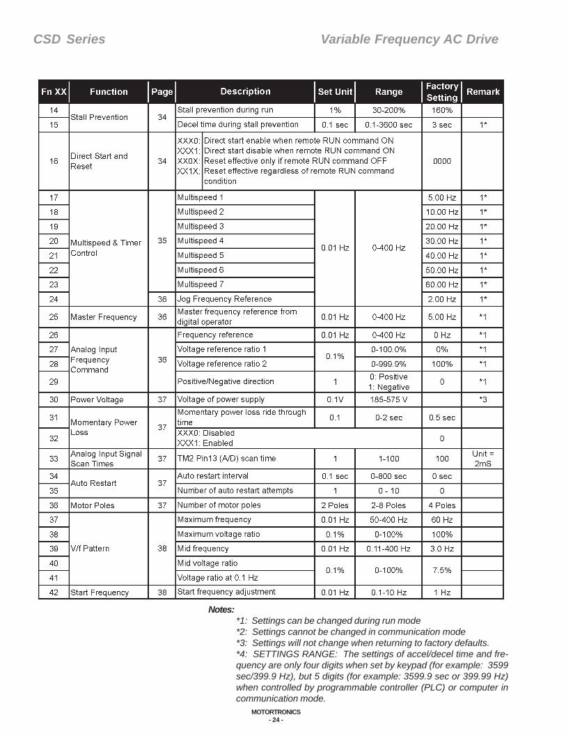
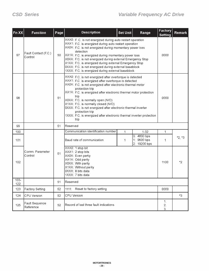
5.1.1 The CSD Function ListThe following list includes the basic information on each function withinthe CSD. For detailed function information, review the referenced page.Also, the Function Notes, in and at the end of this section, are for anyadditional operator notes.
Table 5 B - CSD Function List
CSD Series Variable Frequency AC Drive
MOTORTRONICS- 24 -
Notes:*1: Settings can be changed during run mode*2: Settings cannot be changed in communication mode*3: Settings will not change when returning to factory defaults.*4: SETTINGS RANGE: The settings of accel/decel time and fre-quency are only four digits when set by keypad (for example: 3599sec/399.9 Hz), but 5 digits (for example: 3599.9 sec or 399.99 Hz)when controlled by programmable controller (PLC) or computer incommunication mode.

CSD Series Variable Frequency AC Drive
MOTORTRONICS- 25 -
Notes:*1: Settings can be changed during run mode*2: Settings cannot be changed in communication mode*3: Settings will not change when returning to factory defaults.*4: SETTINGS RANGE: The settings of accel/decel time and fre-quency are only four digits when set by keypad (for example: 3599sec/399.9 Hz), but 5 digits (for example: 3599.9 sec or 399.99 Hz)when controlled by programmable controller (PLC) or computer incommunication mode.

CSD Series Variable Frequency AC Drive
MOTORTRONICS- 26 -

CSD Series Variable Frequency AC Drive
MOTORTRONICS- 27 -
Notes:*1: Settings can be changed during run mode*2: Settings cannot be changed in communication mode*3: Settings will not change when returning to factory defaults.*4: SETTINGS RANGE: The settings of accel/decel time and fre-quency are only four digits when set by keypad (for example: 3599sec/399.9 Hz), but 5 digits (for example: 3599.9 sec or 399.99 Hz)when controlled by programmable controller (PLC) or computer incommunication mode.
CSD Series Variable Frequency AC Drive
MOTORTRONICS- 28 -
CSD Series Variable Frequency AC Drive
MOTORTRONICS- 29 -
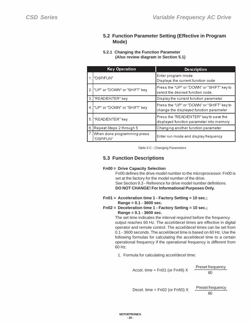
5.2 Function Parameter Setting (Effective in Program Mode)
5.2.1 Changing the Function Parameter(Also review diagram in Section 5.1)
1. Formula for calculating accel/decel time:
Accel. time = Fn01 (or Fn49) X
Decel. time = Fn02 (or Fn50) X
Table 5 C - Changing Parameters
5.3 Function Descriptions
Fn00 = Drive Capacity SelectionFn00 defines the drive model number to the microprocessor. Fn00 isset at the factory for the model number of the drive.See Section 9.3 - Reference for drive model number definitions.DO NOT CHANGE! For Informational Purposes Only.
Fn01 = Acceleration time 1 - Factory Setting = 10 sec.;Range = 0.1 - 3600 sec.
Fn02 = Deceleration time 1 - Factory Setting = 10 sec.;Range = 0.1 - 3600 sec.
The set time indicates the interval required before the frequencyoutput reaches 60 Hz. The accel/decel times are effective in digitaloperator and remote control. The accel/decel times can be set from0.1 - 3600 seconds. The accel/decel time is based on 60 Hz. Use thefollowing formulas for calculating the accel/decel time to a certainoperational frequency if the operational frequency is different from60 Hz.
Preset frequency
Preset frequency60
60
CSD Series Variable Frequency AC Drive
MOTORTRONICS- 30 -
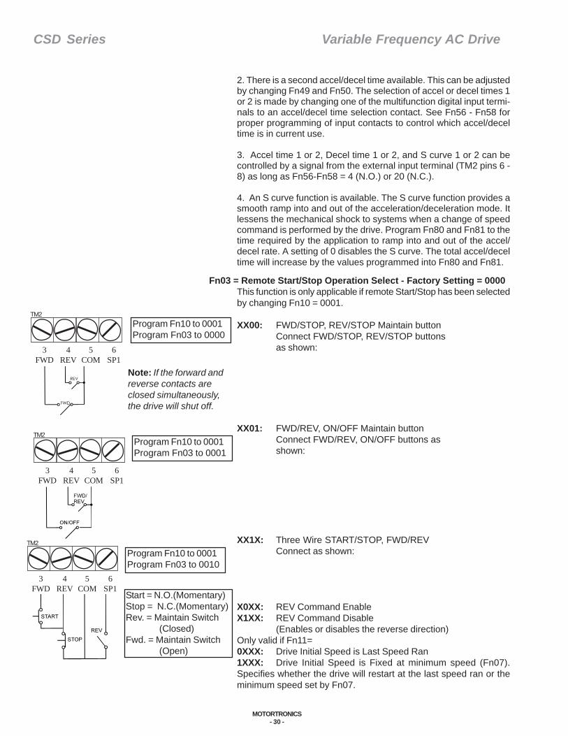
Fn03 = Remote Start/Stop Operation Select - Factory Setting = 0000This function is only applicable if remote Start/Stop has been selectedby changing Fn10 = 0001.
XX00: FWD/STOP, REV/STOP Maintain buttonConnect FWD/STOP, REV/STOP buttonsas shown:
XX01: FWD/REV, ON/OFF Maintain buttonConnect FWD/REV, ON/OFF buttons asshown:
XX1X: Three Wire START/STOP, FWD/REVConnect as shown:
X0XX: REV Command EnableX1XX: REV Command Disable
(Enables or disables the reverse direction)Only valid if Fn11=0XXX: Drive Initial Speed is Last Speed Ran1XXX: Drive Initial Speed is Fixed at minimum speed (Fn07).Specifies whether the drive will restart at the last speed ran or theminimum speed set by Fn07.
2. There is a second accel/decel time available. This can be adjustedby changing Fn49 and Fn50. The selection of accel or decel times 1or 2 is made by changing one of the multifunction digital input termi-nals to an accel/decel time selection contact. See Fn56 - Fn58 forproper programming of input contacts to control which accel/deceltime is in current use.
3. Accel time 1 or 2, Decel time 1 or 2, and S curve 1 or 2 can becontrolled by a signal from the external input terminal (TM2 pins 6 -8) as long as Fn56-Fn58 = 4 (N.O.) or 20 (N.C.).
4. An S curve function is available. The S curve function provides asmooth ramp into and out of the acceleration/deceleration mode. Itlessens the mechanical shock to systems when a change of speedcommand is performed by the drive. Program Fn80 and Fn81 to thetime required by the application to ramp into and out of the accel/decel rate. A setting of 0 disables the S curve. The total accel/deceltime will increase by the values programmed into Fn80 and Fn81.
Program Fn10 to 0001Program Fn03 to 0000
TM2
3FWD
4REV
5COM
6SP1
Note: If the forward andreverse contacts areclosed simultaneously,the drive will shut off.
Program Fn10 to 0001Program Fn03 to 0001
TM2
3FWD
4REV
5COM
6SP1
Program Fn10 to 0001Program Fn03 to 0010
Start = N.O.(Momentary)Stop = N.C.(Momentary)Rev. = Maintain Switch
(Closed)Fwd. = Maintain Switch
(Open)
TM2
3FWD
4REV
5COM
6SP1

CSD Series Variable Frequency AC Drive
MOTORTRONICS- 31 -
Note: Emergency Stop ModeEven when the drive is in the remote start/stop mode, the stop buttonon the mounted keypad can be used to stop the drive in an emergencystop mode. To enable this feature program Fn48 = XX0X. To disablethis feature, program Fn 48 = XX1X. If the stop button on the mountedkeypad is depressed, the drive must be powered down to reset.
Fn04 = Parameter Lock Select - Factory Setting = 0000Prevents accidental changing of parameters (Fn17-25).XXX0: Fn17 - 25 ENABLED
Allows access to the preset speed functionsXXX1: Fn17 - 25 DISABLED
Protects the preset speed functionsXXOX: ALL PARAMETERS EXCEPT Fn17 - 25 ENABLED
Allows access to all parameters excluding the preset speedsXX1X: ALL PARAMETERS EXCEPT Fn 17 - 25 DISABLED
Protects all other parameters except the preset speeds
Fn05 = V/f Pattern Selection - Factory Setting = 9; Range = 0 - 18The CSD Series drive offers 18 preprogrammed V/f patterns for a varietyof applications. Fn05 determines which pattern is applied. In additionto the 18 predefined patterns the user can custom design a V/f patternwhen Fn05=18. Programming Fn05 = 18 enables Fn37 - Fn41, whichdetermines the shape of the custom V/f pattern.0 or 9: General purpose (GP) applications, choose 0 (for
50 Hz) or 9 (for 60 Hz).1,2,3,10,11,12: Constant torque (CT) applications, choose 1-3 (50
Hz) or 10-12 (60 Hz).4,5,13,14: Variable torque (VT) applications, choose 4-5 (50
Hz) or 13-14 (60 Hz).6,7,8,15,16,17: Constant horsepower (CHP) applications, choose
6-8 (50 Hz) or 15-17 (60 Hz).18: Custom programmed V/F pattern (Enables Fn37 -
Fn41).
After choosing your V/f pattern, run motor under worse case loading.A properly programmed drive should spin a loaded motor at 10 Hz. Ifthe motor does not spin at a frequency of 10 Hz, choose a higherstarting torque V/f pattern. If there is not a suitable preprogrammed V/f pattern for the application, change Fn05 = 18 and select the requiredvalues for Fn37 - Fn41 to satisfy the application’s requirements. Reviewthe charts for the correct programming of the customer V/f patternsettings.
The tables and graphs describe the preprogrammed V/f patterns available:
CSD-2P5 - 203 & CSD 401 - 405
CSD-205 - 210, CSD-407 - 410
CSD-215 - 230, CSD-415 - 430
Table 5 D - V/f Pattern Selection
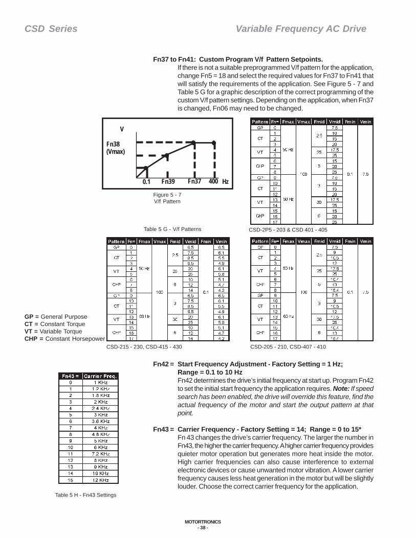
GP = General PurposeCT = Constant TorqueVT = Variable TorqueCHP = Constant Horsepower
Figure 5 - 3V/f Pattern Selection
V
Fn38(Vmax)
Fn40(Vmid)
0.1 Fn39 Fn37 400 Hz

CSD Series Variable Frequency AC Drive
MOTORTRONICS- 32 -
Fn06 = Frequency output upper limit - Factory Setting = 60 Hz; Range = 0 - 400 Hz
Fn07 = Frequency output lower limit - Factory Setting = 0; Range = 0 - 400 HzFn06 and Fn07 program maximum and minimum allowablefrequencies. The drive will not increase the frequency to a value >Fn06. The drive will not decrease the frequency to a value < Fn 07 aslong as a run command is maintained.IMPORTANT!!!If Fn07 = 0 Hz, the drive output will be stopped if the frequencycommand reaches 0 Hz. If Fn07>0 Hz and a run command exists,the drive will run at the frequency of Fn07 even if the frequency commandis lower than the frequency setting of Fn07.
Digital Multifunction Output. (See Fn61 on page 36 for description andexamples.)
Fn08 = Fn12 = Stall Prevention During Accel/Decel/Running:Fn09 = Up to frequency setting detection bandwidth -
Factory Setting = 0; Range = 0 - 30 HzFn61 = Multifunction output
Fn10 = Start/Stop Control Mode Select - Factory Setting = 0Used to control the source of the start/stop signal.0: Digital operator control - If the keypad is to be the source of the start/
stop command signal.1: Remote control - If the terminal strip TM2 is to be the source of the
start/stop command signal.If using the terminal strip for start/stop control, ensure that Fn03 isalso correctly programmed.Note: Even when the drive is in the remote start/stop mode, the stopbutton on the keypad can be used to stop the drive in an emergencystop mode. To enable this feature, program Fn48 = XX0X. To disablethis feature, program Fn48 = XX1X.Note: The start/stop command is set via TM2 when Fn10 = 1 andany multifunction terminal (Fn56-58) is programmed as an opencontrol signal selector switch (Fn56-58 = 9). The start/stop commandis keypad controlled when the signal selector switch is closed andFn56-58 = 9.
Fn11 = Frequency Command Method Select - Factory Setting = 0Determines the drive’s control method of output frequency.0: The keypad arrow keys are used to control the drive speed. In this
mode, the arrow keys change the display to the new desired frequency.Then press the read/enter key to enter the new speed into the drive.
1: The potentiometer mounted on the keypad controls the drive speed.Turn the potentiometer fully counterclockwise to reduce the drivefrequency to minimum. Turn the potentiometer fully clockwise toincrease the drive frequency to maximum.Note: When Fn11 = 1 and one of the multifunction terminals 6 - 8 =15, the frequency is set by the potentiometer on the keypad when themultifunction terminal input is off. When the multifunction terminalinput is on, the frequency is set by the analog input on TM2 pins 13and 14.
2: Run by potentiometer connected to TM2 (terminal 12-14)When Fn11 = 2 the analog speed signal brought into TM2 pin 13 willcontrol the speed of the drive. Several modes of control can be achieved:

CSD Series Variable Frequency AC Drive
MOTORTRONICS- 33 -
*For 0-5 VDC analog command signal control: connect the commandsignal positive to TM2-13 and the command signal negative toTM2-14.Also install the shorting plug on JP1 pins 1 and 2.*For 0-10 VDC analog command signal control: connect the commandsignal positive to TM2-13 and the command signal negative to TM2-14. Also install the shorting plug on JP2 pins 2 and 3.*For 4-20MA analog command signal control: connect the commandsignal positive to TM2-13 and the command signal negative to TM2-14. Also install the shorting plug on JP1 pins 2 and 3.*For potentiometer control: connect the fully clockwise position ofthe potentiometer to TM2-12, connect the wiper of the potentiometerto TM2-13 and connect the fully counter clockwise position of thepotentiometer to TM2-14.Note: The start/stop command is set via the potentiometer on thekeypad when Fn11 = 1 and any multi function terminal (Fn56-58) isprogrammed as an open control signal selector switch (Fn56-58 =9). The start/stop command is keypad controlled when the signalselector switch is closed and Fn56-58 = 9.Note: The start/stop command is set via the analog input on TM2pins 12 - 14 when Fn11 = 2 and any multifunction terminal (Fn56-58)is programmed as an open control signal selector switch (Fn56-58 =9). The start/stop command is keypad controlled when the signalselector switch is closed and Fn56-58 = 9.
3: (Up/Down) Run by multi-function input frequency command(terminals 6-8)When Fn11 = 3 and if Fn56-58 = 12 or 13, the multifunction inputterminals TM2 pins 6 - 8 act as arrow keys to increase and decreasespeed. Programming Fn56 - 58 = 12 changes that particular terminalto an up command. Programming Fn56 - 58 = 13 changes thatparticular terminal to a down command. When the run command ison, the drive will accelerate to the frequency in Fn25. When the upcommand is on, the drive starts to accelerate. When the up commandis off, the drive will stop accelerating and run at constant speed. Whenthe down command is on the drive will start to decelerate and whenthe down command is off the drive will run at constant speed.
Fn12 = Stall Prevention During Accel/Decel/Running:XXX0: Stall prevention during accel enabled
This setting allows the drive to automatically extend the accelerationtime if it detects a stall condition beginning to occur.
XXX1: Disables stall prevention during accel (the above feature)XX0X: Stall prevention during decel enabled
This setting allows the drive to automatically extend the decelerationtime if it detects a stall condition beginning to occur.
XX1X: Disables stall prevention during decel disable (the above feature)X0XX: Stall prevention during running enabled
This setting allows the drive to automatically lower frequency to closelymatch the motor speed and when the stall condition has cleared, willreaccelerate the motor back to operational speed.
X1XX:Disables stall prevention during running (the above feature)0XXX:Stall prevention decel time set by Fn02
The rate at which the drive output will decelerate is dependent uponthe programming of the left most digit of Fn12. If Fn12 = 0XXXdeceleration rate = Fn02.
1XXX: Stall prevention decel time set by Fn15.If Fn12 is 1XXX the deceleration rate = Fn15.
CSD Series Variable Frequency AC Drive
MOTORTRONICS- 34 -
Figure 5 - 4Priority of Running Command
Fn13 = Stall prevention level during accel - Factory Setting = 110%;Range = 30% - 200%Fn13 determines the level of current (measured in percent of driverated current) at which stall prevention will activate when the drive is inthe acceleration mode.
Fn14 = Stall prevention level during running - Factory Setting = 160%;Range = 30% - 200%Fn14 determines the level of current (measured in percent of driverated current) at which stall prevention will activate when the drive is inthe constant speed mode.
Fn15 = Decel time during stall prevention - Factory Setting = 3 Sec.;Range = 0.1 - 3600 secondsFn15 can determine the rate of deceleration if the drive enters the stallprevention mode during constant speed if Fn12 = 1XXX.
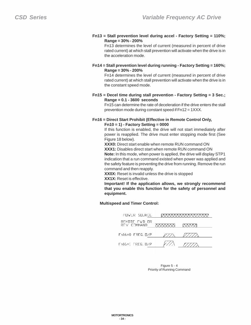
Fn16 = Direct Start Prohibit (Effective in Remote Control Only,Fn10 = 1) - Factory Setting = 0000If this function is enabled, the drive will not start immediately afterpower is reapplied. The drive must enter stopping mode first (SeeFigure 18 below).XXX0: Direct start enable when remote RUN command ONXXX1: Disables direct start when remote RUN command ONNote: In this mode, when power is applied, the drive will display STP1indication that a run command existed when power was applied andthe safety feature is preventing the drive from running. Remove the runcommand and then reapply.XX0X: Reset is invalid unless the drive is stoppedXX1X: Reset is effective.Important! If the application allows, we strongly recommendthat you enable this function for the safety of personnel andequipment.
Multispeed and Timer Control:
CSD Series Variable Frequency AC Drive
MOTORTRONICS- 35 -
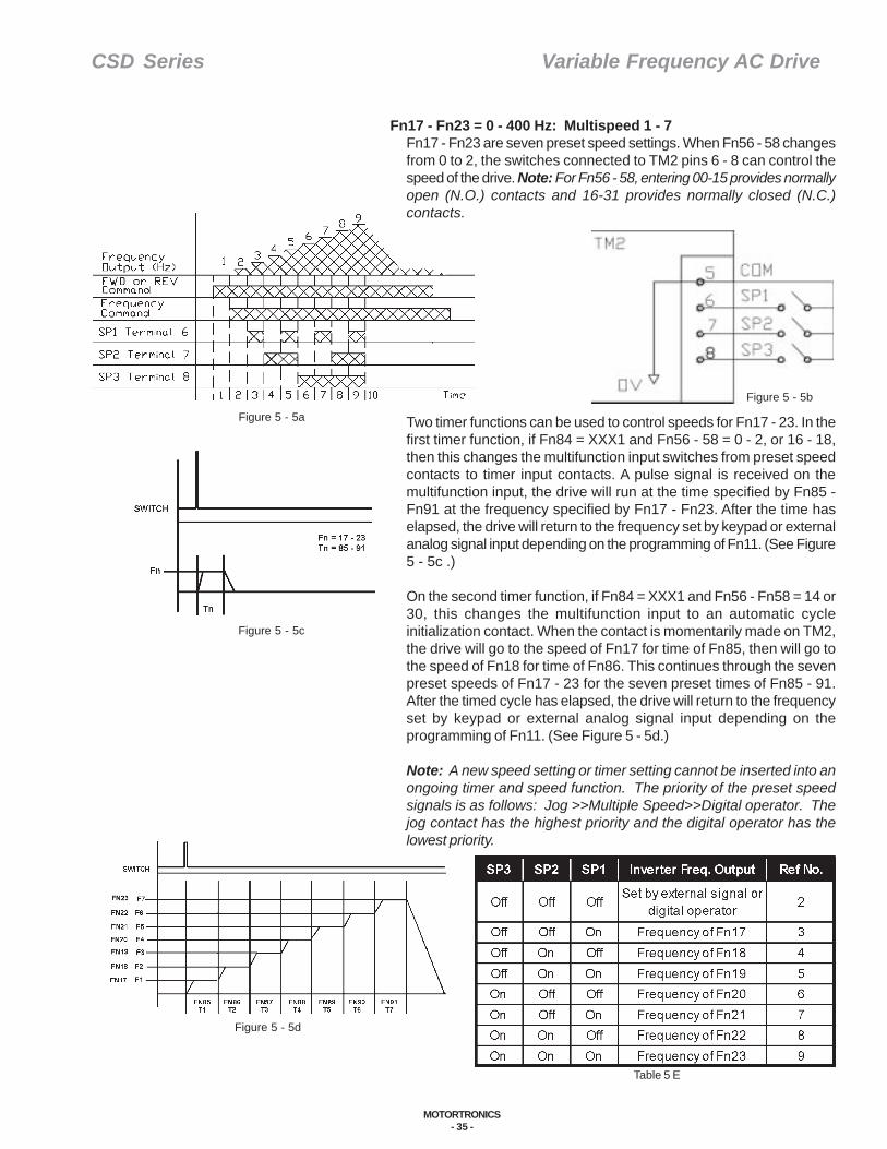
Fn17 - Fn23 = 0 - 400 Hz: Multispeed 1 - 7Fn17 - Fn23 are seven preset speed settings. When Fn56 - 58 changesfrom 0 to 2, the switches connected to TM2 pins 6 - 8 can control thespeed of the drive. Note: For Fn56 - 58, entering 00-15 provides normallyopen (N.O.) contacts and 16-31 provides normally closed (N.C.)contacts.
Figure 5 - 5a
Figure 5 - 5b
Table 5 E
Figure 5 - 5c
Figure 5 - 5d
Two timer functions can be used to control speeds for Fn17 - 23. In thefirst timer function, if Fn84 = XXX1 and Fn56 - 58 = 0 - 2, or 16 - 18,then this changes the multifunction input switches from preset speedcontacts to timer input contacts. A pulse signal is received on themultifunction input, the drive will run at the time specified by Fn85 -Fn91 at the frequency specified by Fn17 - Fn23. After the time haselapsed, the drive will return to the frequency set by keypad or externalanalog signal input depending on the programming of Fn11. (See Figure5 - 5c .)
On the second timer function, if Fn84 = XXX1 and Fn56 - Fn58 = 14 or30, this changes the multifunction input to an automatic cycleinitialization contact. When the contact is momentarily made on TM2,the drive will go to the speed of Fn17 for time of Fn85, then will go tothe speed of Fn18 for time of Fn86. This continues through the sevenpreset speeds of Fn17 - 23 for the seven preset times of Fn85 - 91.After the timed cycle has elapsed, the drive will return to the frequencyset by keypad or external analog signal input depending on theprogramming of Fn11. (See Figure 5 - 5d.)
Note: A new speed setting or timer setting cannot be inserted into anongoing timer and speed function. The priority of the preset speedsignals is as follows: Jog >>Multiple Speed>>Digital operator. Thejog contact has the highest priority and the digital operator has thelowest priority.
CSD Series Variable Frequency AC Drive
MOTORTRONICS- 36 -
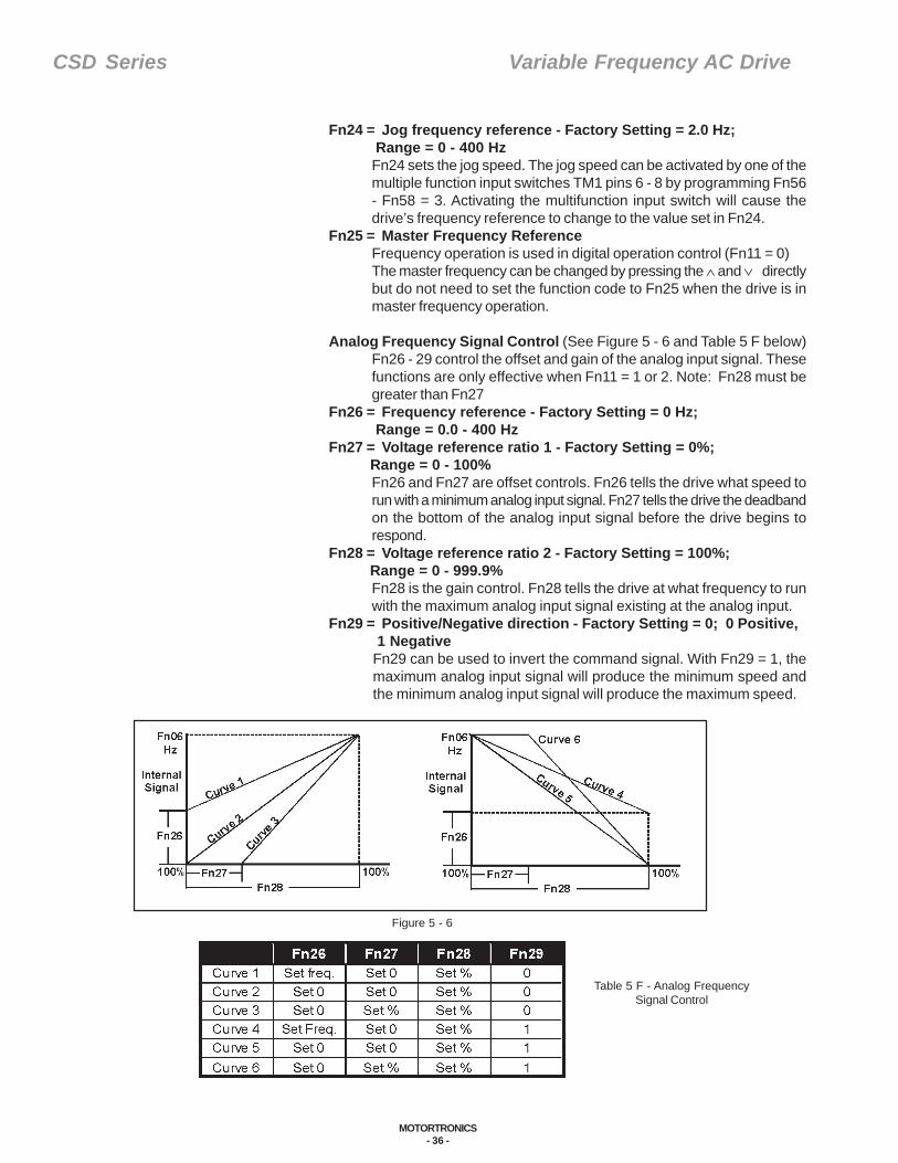
Figure 5 - 6
Table 5 F - Analog FrequencySignal Control
Fn24 = Jog frequency reference - Factory Setting = 2.0 Hz; Range = 0 - 400 Hz
Fn24 sets the jog speed. The jog speed can be activated by one of themultiple function input switches TM1 pins 6 - 8 by programming Fn56- Fn58 = 3. Activating the multifunction input switch will cause thedrive’s frequency reference to change to the value set in Fn24.
Fn25 = Master Frequency ReferenceFrequency operation is used in digital operation control (Fn11 = 0)The master frequency can be changed by pressing the ∧ and ∨ directlybut do not need to set the function code to Fn25 when the drive is inmaster frequency operation.
Analog Frequency Signal Control (See Figure 5 - 6 and Table 5 F below)Fn26 - 29 control the offset and gain of the analog input signal. Thesefunctions are only effective when Fn11 = 1 or 2. Note: Fn28 must begreater than Fn27
Fn26 = Frequency reference - Factory Setting = 0 Hz; Range = 0.0 - 400 HzFn27 = Voltage reference ratio 1 - Factory Setting = 0%; Range = 0 - 100%
Fn26 and Fn27 are offset controls. Fn26 tells the drive what speed torun with a minimum analog input signal. Fn27 tells the drive the deadbandon the bottom of the analog input signal before the drive begins torespond.
Fn28 = Voltage reference ratio 2 - Factory Setting = 100%; Range = 0 - 999.9%
Fn28 is the gain control. Fn28 tells the drive at what frequency to runwith the maximum analog input signal existing at the analog input.
Fn29 = Positive/Negative direction - Factory Setting = 0; 0 Positive, 1 Negative
Fn29 can be used to invert the command signal. With Fn29 = 1, themaximum analog input signal will produce the minimum speed andthe minimum analog input signal will produce the maximum speed.

CSD Series Variable Frequency AC Drive
MOTORTRONICS- 37 -
Fn30 = Voltage of Power SupplyFn30 must be programmed to the supply voltage. Fn30 provides thecorrect voltage to the motor for the various V/f patterns. It also determinesthe braking transistor setpoint.
Restart From Momentary Power Loss:Fn31 and Fn32 allow the drive to ride through a momentary power lossof up to two seconds without tripping on undervoltage. When the powercomes back, if it is within the time set by Fn31, the drive tracks themotor at its current operating speed and then reaccelerates to itsoperational speed. There is no limit to the number of times this featurecan be activated as long as the power loss is less than the value inFn31.
Fn31 = Momentary power loss ride through time - Factory Setting = 0.5 sec; Range = 0 - 2 sec.Fn32 = XXX0: Disable
XXX1: EnableIf the power loss time is greater than Fn31 and the application requiresthat the drive still restart upon reapplication of power, program Fn34and Fn35 to allow automatic reset of a fault and restart of the drive.
Fn33 = Analog Input Signal Scan Times -Factory Setting = 100 2ms; Range = 0 - 100 2msThe value of terminal 13 (A/D) input signal is scanned at a rate of 2ms.The drive calculates the average value of this signal based on (2msxFn33). The drive will then respond to this calculated speed, filtering outnoise on the command signal line.
Auto RestartFn34 and Fn35 allow the drive to automatically reset a fault condition,restart the drive and use speed search to return the motor to speedafter the fault condition clears.
Fn34 = Auto Restart Interval - Factory Setting = 0 sec;Range = 0 - 800 sec.
Fn35 = Number of Auto Restart Attempts - Factory Setting = 0;Range = 0 - 10 times:Programming Fn35 = 0 disables this feature.To enable this feature, program Fn35 to the maximum number of timesthe drive will attempt to reset the fault. Program Fn34 to the delayperiod between the fault condition notice and the subsequent fault resetby the drive. Auto restart is only effective if the drive is in the run mode.The number of auto restart attempts will be reset after either 10 minuteshas elapsed without a fault condition or the reset key is depressed onthe keypad or via TM2.Note: Fn97 determines when the fault contact (TM2 pins 1 and 2) willenergize on a fault if the auto restart circuit is trying to restart themotor. If Fn97 =XXX0, the fault terminal will not function while autorestart is working (except for an OL fault). If Fn 97 = XXX1 the faultterminal will function even while auto restart is working.
Fn36 = Display Mode Control - Factory Setting = 4 Poles;Range = 2-8 motor polesFn36 tells the drive the number of poles in the motor. The drive usesthis number to calculate the RPM of the motor at a given frequency.This number can be displayed on the keypad by programming Fn51 =1. Program into Fn36 the number of motor poles.
CSD Series Variable Frequency AC Drive
MOTORTRONICS- 38 -
Fn37 to Fn41: Custom Program V/f Pattern Setpoints.If there is not a suitable preprogrammed V/f pattern for the application,change Fn5 = 18 and select the required values for Fn37 to Fn41 thatwill satisfy the requirements of the application. See Figure 5 - 7 andTable 5 G for a graphic description of the correct programming of thecustom V/f pattern settings. Depending on the application, when Fn37is changed, Fn06 may need to be changed.
GP = General PurposeCT = Constant TorqueVT = Variable TorqueCHP = Constant Horsepower
Table 5 G - V/f Patterns
Fn42 = Start Frequency Adjustment - Factory Setting = 1 Hz;Range = 0.1 to 10 HzFn42 determines the drive’s initial frequency at start up. Program Fn42to set the initial start frequency the application requires. Note: If speedsearch has been enabled, the drive will override this feature, find theactual frequency of the motor and start the output pattern at thatpoint.
Fn43 = Carrier Frequency - Factory Setting = 14; Range = 0 to 15*Fn 43 changes the drive’s carrier frequency. The larger the number inFn43, the higher the carrier frequency. A higher carrier frequency providesquieter motor operation but generates more heat inside the motor.High carrier frequencies can also cause interference to externalelectronic devices or cause unwanted motor vibration. A lower carrierfrequency causes less heat generation in the motor but will be slightlylouder. Choose the correct carrier frequency for the application.
CSD-205 - 210, CSD-407 - 410CSD-215 - 230, CSD-415 - 430
CSD-2P5 - 203 & CSD 401 - 405
V
Fn38(Vmax)
0.1 Fn39 Fn37 400 Hz
Figure 5 - 7V/f Pattern
Table 5 H - Fn43 Settings

CSD Series Variable Frequency AC Drive
MOTORTRONICS- 39 -
Fn44 = Stopping Mode and Braking Resistor Protection -Factory Setting = 0000Controls the stopping style and the brake resistor protection circuit.XXX0: Decel to stop with a stop command.XXX1: Free run (coast) to stop with a stop command.XX0X: Braking resistor overheat protection disableXX1X: Braking resistor overheat protection enable - the drivemonitors brake resistor current and if too much current is detectedin the resistor in too short a period of time, the drive will trip and OH1will be displayed. The drive will reset after the brake resistor coolsoff.
Multifunction Analog OutputThe multifunction analog output (TM2-15) can be used to track severaldifferent parameters of the drive. The output of terminal 15 is 0-10VDC at a maximum current draw of 1mA.
Fn45 = Gain of multifunction analog output - Factory Setting = 100%;Range - 0-200%A gain control to compensate for inaccuracies of external monitoringequipment.
Fn46 = Multifunction analog output selection - Factory Setting = 0;Range = 0-30: Output freq. (Fn06 max) 10VDC/Fn06 - enables the output tofollow the drive output frequency.1: Set frequency (Fn06 max) 10VDC/Fn06 - enables this output tofollow the set frequency.2: Output voltage (VAC): 10VDC/Fn30 - enables this output to followthe output AC voltage of the drive.3: DC voltage (VPN): 10VDC/450VDC/900VDC for 400V series -enables the output to follow the DC bus voltage program.
Fn47 = Display Mode Control - Factory Setting = 0000Fn47 can add several parameters to the keypad display.XXX0: Disables output voltage displayXXX1: Enables output voltage display on the keypadXX0X: Disables DC bus voltage current displayXX1X: Enables DC bus voltage current display on the keypadX0XX: Disables output current displayX1XX: Enables output current display on the keypadThe customer can toggle between these displays with the DSP/FUNkey on the keypad. To toggle through various displays, depress theDSP/FUN key. (See Figure 5 - 8.)
Fn48 = Dynamic Braking and Priority of Stopping and Speed Searchand AVR Control -Factory Setting = 0000Fn48 controls several parametersXXX0: Enhanced braking capacity - controlling the drive’s brakingcapacity, the drive will adjust the output voltage to absorb the inertiaenergy of load and thereby increase the braking capability.XXX1: Standard braking capacity - disables the above feature.XX0X: Stop key effective in remote control mode - allows the stopkey on the keypad to be an emergency stop the drive even in remotecontrol mode. Once the stop key on the keypad is depressed thedrive will stay in a locked out condition until power is cycled to thedrive.
DSPFUN Frequency/RPM/Linear Speed
(As chosen by Fn51)
Programming Mode
Output Voltage
DC Bus Voltage
Output Current
Figure 5 - 8Display Mode Control
CSD Series Variable Frequency AC Drive
MOTORTRONICS- 40 -
XX1X: Stop key ineffective in remote control mode - disables theabove feature.The speed search is used in windmilling applications. The drive willfind the operational speed of the motor and start.X0XX: Speed search controlled by terminals on TM2 - allows theuser to enable speed search at all times or only through one of themultifunction inputs on TM2 pins 6 - 8. Programming Fn56 - Fn58 =7 (N.O.) or 23 (N.C.) converts the input command signal on TM2 tothe speed search enable signal. The speed search capability of thedrive can only be enabled by one of the multifunction input commandson TM2 pins 6 - 8.X1XX: Speed search effective when drive starts0XXX: AVR function effective - enables automatic regulation of motorvoltage.1XXX: AVR function ineffective - disables the above feature.
Fn49 - Fn 50: Refer to Fn01Fn49 = Acceleration Time 2 - Factory Setting = 10.0 sec;Range = 0.1 - 3600 sec.Fn50 = Deceleration Time 2 - Factory Setting = 10.0 sec;Range = 0.1 - 3600 sec.Fn49 and Fn50 provide a second set of acceleration/decelerationtimes. The selection of accel or decel times 1 or 2 is made bychanging one of the multifunction digital input terminals to an accel/decel time selection contact. Set Fn56 - Fn58 = 04(N.O.) or 20(N.C.) to enable the multifunction digital input terminal to be used asan accel/decel time selection switch. Program into Fn49 the requiredsecondary acceleration time and program into Fn50 the requiredsecondary deceleration time.
Display Mode Control - Fn51 and Fn52 can be used to determine the displaymode of the keypad.Fn51 = Factory Setting = 0; Range = 0 - 5Fn52 = Factory Setting = 1800; Range = 0 - 9999
Fn51 = 0: Display frequency (Hz), display preset frequency during stop modeand operation frequency during run mode.1: Display RPM of motor with the formula = (120/Fn 36) X FrequencyOutput where Fn36 is the number of poles of the motor, ensure thatthe correct information is programmed into Fn36.2: Line speed display mode in integral (XXXX) with the formula =(Output Frequency/Fn06) x Fn 523: Line speed display mode in one digit decimal (XXXX) with theformula = (Output Frequency/Fn06) X (Fn52/10)4: Line speed display mode in two digit decimal (XXXX) with theformula = (Output Frequency/Fn06) X (Fn 52/100)5: Line speed display mode in three digit decimal (XXXX) with theformula = (Output Frequency/Fn06) X (Fn 52/1000)

CSD Series Variable Frequency AC Drive
MOTORTRONICS- 41 -
Fn52 = Line speed display in accordance with maximum outputfrequency (Fn06)
Stopping ModeThe CSD drive, after decelerating the load to zero speed applies asmall amount of DC current into the motor to bring the motor to afinal stop. The parameters of this DC injection braking capability aredefined by Fn53 - Fn55. Program Fn53 - Fn55 as required by theapplication.
Fn53 = DC Braking time - Factory Setting = 0.5 sec.; Range = 0 - 25.5 secAmount of time the DC current is applied to the motor.
Fn54 = DC Braking Injection Freq. - Factory Setting = 1.5 Hz.;Range = 0.1 - 10 HzThe frequency at which, while the drive is decelerating, it will switchfrom dynamic braking to DC injection braking.
Fn55 = DC Braking level - Factory Setting = 8%; Range = 0 - 20%Defines the magnitude of the DC current and, thereby, the magnitudeof DC torque to the motor.
Multifunction Input:The multifunction input contacts of TM2 pins 6,7 and 8 can be definedby Fn56 to Fn58.Fn56 defines the functionality of the multifunction digital input contacton TM2-6.Fn57 defines the functionality of the multifunction digital input contacton TM2-7.Fn58 defines the functionality of the multifunction digital input contacton TM2-8.Note: When it is discussed “Programming this function...” Fn56-58is the reference.Note: Changing these functions to 00-15 has normally open (N.O.)contacts or changing to 16-31 has normally closed (N.C.) contacts.
Fn56 - Fn58 = Programming this function with the following:00/16: SP1 (Multispeed 1): Refer to Fn17
- defines this terminal as a preset speed switch #101/17: SP2 (Multispeed 2): Refer to Fn17
- defines this terminal as a preset speed switch #202/18: SP3 (Multispeed 3): Refer to Fn17
- defines this terminal as a preset speed switch #3.
By programming these terminals as preset speed contacts, the drivecan be run at up to seven different speeds depending on the switchposition. Example: Function 56 = 00, 57 = 01 and 58 = 02. For moreinformation, review page 32 for Fn17 - Fn23. This table represents theoutput of the drive for various switch combinations:
03/19: Jog operation: Refer to Fn17Defines this terminal as a jog speed switch. By programming one ofthe multifunction switches as a jog contact, it can be used to forcethe output frequency to the value in Fn24.
04/20: Accel/Decel time selection: Refer to Fn01 - point 2Defines thisterminal as a second accel/decel time switch. By programming oneof the multifunction switches as second accel/decel time switch thecustomer can select between Fn01 and Fn02 controlling accel/deceltime and Fn49 and Fn50 controlling accel/decel time.
Table 5 I - Multi Speed Output
CSD Series Variable Frequency AC Drive
MOTORTRONICS- 42 -
05/21: External emergency stopDefines this terminal as an emergency stop command. Byprogramming one of the multifunction switches as an emergency stopthe customer can override a run command and force the drive todecelerate to a stop. Once the emergency stop signal is removed, therun/stop command must be removed and reengaged to get the driveto restart. The fault contact is controlled by Fn97 as follows:
Fn97= X0XX: Fault contact is not energized after external emergency stopsignal is receivedX1XX: Fault contact is energized after external emergency stopsignal is received
06/22: External baseblockDefines this terminal as a base block command (coast to a stop). Byprogramming one of the multifunction switches as a baseblock contact,the customer can override a run command and force the drive’s outputto turn off immediately allowing the motor to coast to a stop. After thebaseblock command disappears, the run/stop command must beremoved and reapplied to restart the drive. The fault contact is controlledby Fn97 as follows:
Fn97 = 0XXX: Fault contact is not energized after external baseblock.1XXX: Fault contact is energized after external baseblock.
07/23: Speed search: Refer to Fn48Defines this terminal as a speed search command. This feature isonly available if Fn48 = X0XX. When one of the multifunction inputcommand signals is programmed to a speed search contact, the drivecan be remotely instructed to either start at the initial frequencyreference of Fn42 or start using the speed search feature. Energizingthe multifunction input that is programmed at the speed search contactwill allow the drive to use speed search for its start frequency. De-energizing the multifunction input that is programmed as the speedsearch contact will allow the drive to use Fn42 as its starting frequency.
08/24: Energy saving mode: Refer to Fn82Defines this terminal as an energy saving mode switch. This featureis only available if Fn82 = XX01. When the contact is energized, theoutput voltage of the drive will be adjusted to minimize the amount ofenergy required to maintain motor speed. With this contact de-energizedthe output voltage will be a function of the V/F pattern only.
09/25: Control signal selectionDefines this terminal as a control signal selection switch. Byprogramming one of the multifunction switches as a control signalselection switch the customer can remotely select the source of thespeed reference signal as a start stop signal as described below.When the multi-input terminal is OFF, the Operation command and/orFrequency command is either from digital operator or remote control(TM2) - according to the settings of Fn10/Fn11. When the multi-inputterminal is ON, the operation command and/or frequency commandis from the digital operator regardless of the settings of Fn10/Fn11.
10/26: Communication control mode selectionDefines this terminal as a communication enable/disable switch. Byprogramming a multifunction input switch as a communication controlmode selection switch, the customer can select whether the unitaccepts its command signals through the communications port onCon 12, or via the keypad on the drive. With the multi-input terminaloff during communication, the drive can receive run/stop and frequencycommand signal from external communication source. The function
CSD Series Variable Frequency AC Drive
MOTORTRONICS- 43 -
parameters can be changed by the external communication source.The keypad and TM2 signals for run/stop and frequency control will bedisabled. The keypad can still be used for displaying voltage/current/frequency or emergency stop but the keypad can not be used forchanging function parameters. With the multi-input terminal on duringcommunication, the drive run/stop and frequency command signal iscontrolled by the drive itself. The external communication source canstill read parameters but will not be able to control start/stop or thefrequency reference.
11/27: Accel/Decel prohibitDefines this terminal as a Accel/Decel prohibit contact. By programmingone of the multifunction input contacts to an accel/decel prohibit signal,the contact can be used to momentarily stop acceleration or deceleration.When the contact is de-energized, the drive will continue to accelerateor decelerate to its final value.
12/28: UP command13/29: DOWN command
Defines this terminal as an up command contact. Programming thisfunction to 13 (N.O.) or 29(N.C.) defines this terminal as a down commandcontact. This function is only active if Fn 11=3. By Programming themultifunction input contact as an up or down command contact, thecustomer is able to remote the up/down commands that currently existon the keypad. When the up contact is energized, the drive will increasespeed until the up contact is de-energized. When the down contact isenergized, the drive will decrease speed until the down contact is de-energized. If both contacts are energized at the same time the drive willnot accelerate or decelerate until one or the other direction is selected.“Zero speed stop” control can be available if DOWN command is onconstantly. Drives start to run out of the “zero speed stop” mode if UPcommand is energized.Note: In STOP mode the UP/DOWN command is ineffective.
14/30: Sequence control: Refer to Fn17 and Fn84-Fn91Defines this terminal as an auto sequence initialization contact. Thisfeature is only available with Fn84 = XXX1. When Fn84 = XXX1 and Fn56-58 = 14 or 30 this changes the multifunction input to an auto sequenceinitialization switch. When the contact is momentarily made on TM2the drive will go to the speed of Fn17 for time of Fn85, then will go tospeed of Fn18 for time of Fn86 and so on through the seven presetspeeds of Fn17 - 23 for the seven preset times of Fn85 - 91. After thetimed cycle has elapsed, the drive will return to frequency set by keypador external analog signal input depending on the programming of Fn11.Note: A new speed setting or timer setting cannot be inserted into anongoing timer and speed function.
15/31:Master/Auxiliary speed selection: Refer to Fn11 Defines this terminal as a master/auxiliary speed switch. This feature
is only available with Fn11 = 1 or 2. When Fn11 = 1 and the master/auxiliary speed switch is de-energized, the potentiometer mounted onthe keypad will control the speed of the drive. Turning the potentiometerfully counterclockwise will reduce the frequency of the drive to minimum.Turning the potentiometer fully clockwise will increase the frequency ofthe drive to maximum. When the master/auxiliaryspeed switch isenergized, the frequency is set by the analog input on TM2 pins 13 and14. When Fn 11 = 2 and the master/auxiliary speed switch is de-energized, the analog speed signal brought into TM2 pin 13 will controlthe speed of the drive. When the master/auxiliary speed switch isenergized, the frequency is set by the potentiometer on the keypad.

CSD Series Variable Frequency AC Drive
MOTORTRONICS- 44 -
16-31: Changes 00-15 N.O. (normally open) contact to N.C. (normallyclosed) contact
Fn59 - Fn 60 = Reserved
Fn61 = Digital Multifunction Output - Factory Setting = 00;Range = 00 - 11The open collector transistor output of TM1 pins 10 & 11 are used forseveral indications. Note that TM2 pins 10 and 11 is an open collectoroutput rated for 50mA, 35 VDC. Do not apply AC voltage to this contact.Applying AC voltage to this contact will cause failure of the drive. Alsoapplying DC voltage in the reverse polarity will cause failure of thedrive. Program Fn61 for the style of control required of the open collectoroutput. Entering a value 00-05 equals normally open (N.O.) contactsand entering a value of 06-11 equals normally closed (N.C.) contacts.Following is a description of functions for certain values of Fn61:
00/06: Run mode places the open collector output transistor in the run mode.Whenever, the output of the drive is > 0 Hz, the transistor will be on.When the output of the drive is = 0 Hz, the transistor will be off.Programing Fn61 = 06 places the open collector output transistor inthe run mode. Whenever the output of the drive is > 0 Hz, the transistorwill be off. When the output of the drive is = 0 Hz the transistor will beon.
01/07: Up to desired frequency Fn61 = 01 places the open collector outputtransistor in the up to desired frequency mode. Whenever the outputof the drive is at constant speed, the transistor will be on. When thedrive is not up to desired frequency the transistor will be off.Programming Fn61 = 07 places the open collector out put transistorin the up to desired frequency mode. Whenever the output of the driveis at constant speed the transistor will be off. When the drive is not upto the desired frequency the transistor will be on.
02/08: Set frequency output - Fn08+/- Fn09 places the open collector outputtransistor in the bandwidth mode. Whenever the output of the drive isin agreement with the value in Fn08 plus or minus the value in Fn09the transistor will be on. When the output of the drive is not in agreementwith the value in Fn08 plus or minus the value in Fn09, the transistorwill be off. Programming Fn61 = 08 places the open collector outputtransistor in the band width mode. Whenever the output of the drive isin agreement with the value in Fn08 + Fn09 the transistor will be off.When the output of the drive is not in agreement with the value in Fn08+ Fn09, the transistor will be on.
03/09: Frequency detection > Fn08 Places the open collector output transistor in the frequency detection
greater than mode. Whenever the output of the drive is > Fn08 thetransistor will be on. Whenever the output of the drive is < Fn08 thetransistor will be off. Programming Fn61 = 09 places the open collectoroutput transistor in the frequency detection greater than mode.Whenever the output of the drive is > Fn08 the transistor will be off.
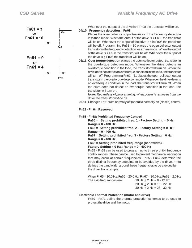
CSD Series Variable Frequency AC Drive
MOTORTRONICS- 45 -
Whenever the output of the drive is < Fn08 the transistor will be on.04/10: Frequency detection < Fn08
Places the open collector output transistor in the frequency detectionless than mode. When the output of the drive is < Fn08 the transistorwill be on. Whenever the output of the drive is > in Fn08 the transistorwill be off. Programming Fn61 = 10 places the open collector outputtransistor in the frequency detection less than mode. When the outputof the drive is < Fn08 the transistor will be off. Whenever the output ofthe drive is > Fn08 the transistor will be on.
05/11: Over torque detection places the open collector output transistor inthe overtorque detection mode. Whenever the drive detects anovertorque condition in the load, the transistor will turn on. When thedrive does not detect an overtorque condition in the load, the transistorwill turn off. Programming Fn61 = 11 places the open collector outputtransistor in the overtorque detection mode. Whenever the drive detectsan overtorque condition in the load, the transistor will turn off. Whenthe drive does not detect an overtorque condition in the load, thetransistor will turn on.Note: Regardless of programming, when power is removed from thedrive the transistor will be off.
06-11: Changes Fn61 from normally off (open) to normally on (closed) control.
Fn62 - Fn 64: Reserved
Fn65 - Fn68: Prohibited Frequency ControlFn65 = Setting prohibited freq. 1 - Factory Setting = 0 Hz;Range = 0 - 400 HzFn66 = Setting prohibited freq. 2 - Factory Setting = 0 Hz.;Range = 0 - 400 HzFn67 = Setting prohibited freq. 3 - Factory Setting = 0 Hz.;Range = 0 - 400 HzFn68 = Setting prohibited freq. range (bandwidth) -Factory Setting = 0 Hz.; Range = 0 - 400 HzFn65 - Fn68 can be used to program up to three prohibit frequencycontrol ranges. These can be used to prevent mechanical oscillationthat may occur at certain frequencies. Fn65 - Fn67 determine thethree distinct frequency setpoints to be avoided by the drive. Fn68defines the band width around these frequencies to be avoided bythe drive. For example:
When Fn65 = 10.0 Hz, Fn66 = 20.0 Hz, Fn 67 = 30.0 Hz, Fn68 = 2.0 HzThe skip freq. ranges are: 10 Hz + 2 Hz = 8 - 12 Hz
20 Hz + 2 Hz = 18 - 22 Hz30 Hz + 2 Hz = 28 - 32 Hz
Electronic Thermal Protection (motor and drive)Fn69 - Fn71 define the thermal protection schemes to be used toprotect the drive and the motor.
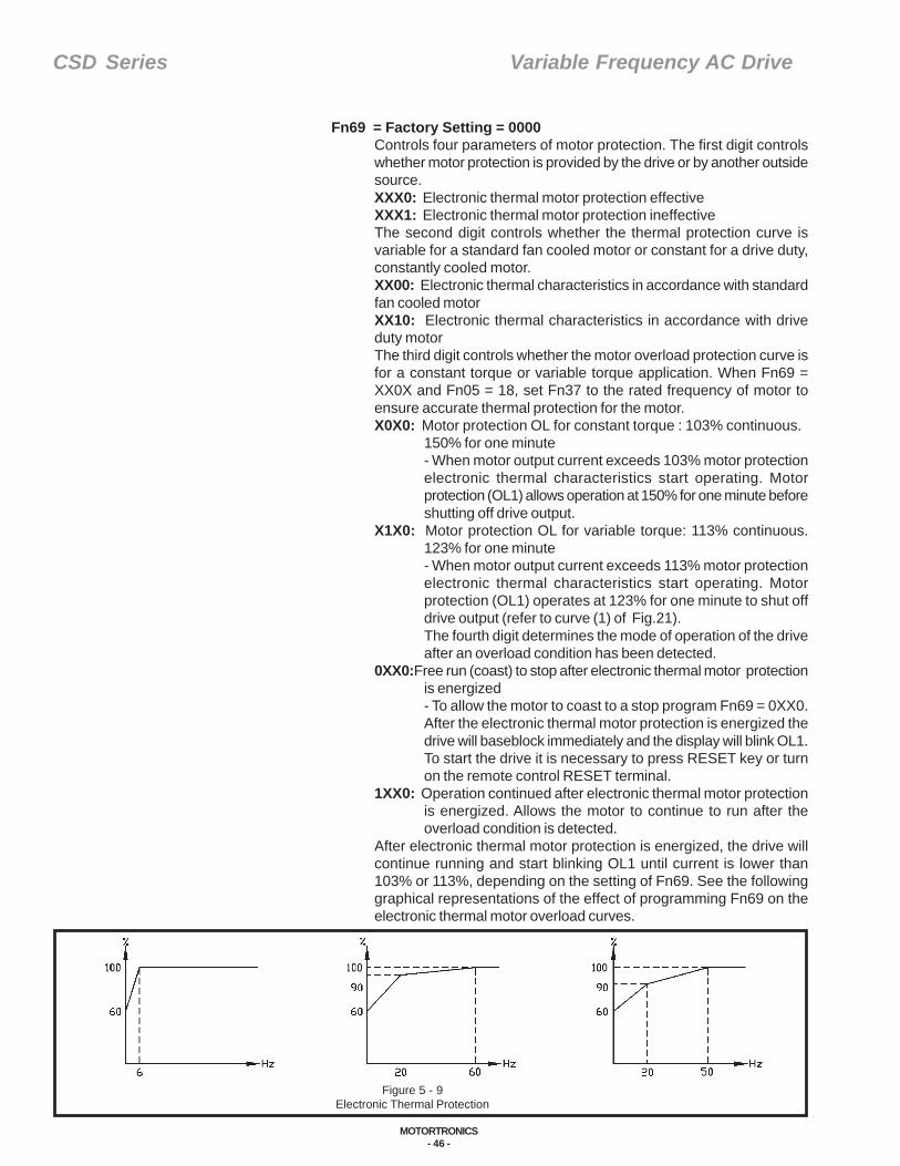
CSD Series Variable Frequency AC Drive
MOTORTRONICS- 46 -
Fn69 = Factory Setting = 0000Controls four parameters of motor protection. The first digit controlswhether motor protection is provided by the drive or by another outsidesource.XXX0: Electronic thermal motor protection effectiveXXX1: Electronic thermal motor protection ineffectiveThe second digit controls whether the thermal protection curve isvariable for a standard fan cooled motor or constant for a drive duty,constantly cooled motor.XX00: Electronic thermal characteristics in accordance with standardfan cooled motorXX10: Electronic thermal characteristics in accordance with driveduty motorThe third digit controls whether the motor overload protection curve isfor a constant torque or variable torque application. When Fn69 =XX0X and Fn05 = 18, set Fn37 to the rated frequency of motor toensure accurate thermal protection for the motor.X0X0: Motor protection OL for constant torque : 103% continuous.
150% for one minute- When motor output current exceeds 103% motor protectionelectronic thermal characteristics start operating. Motorprotection (OL1) allows operation at 150% for one minute beforeshutting off drive output.
X1X0: Motor protection OL for variable torque: 113% continuous.123% for one minute- When motor output current exceeds 113% motor protectionelectronic thermal characteristics start operating. Motorprotection (OL1) operates at 123% for one minute to shut offdrive output (refer to curve (1) of Fig.21).The fourth digit determines the mode of operation of the driveafter an overload condition has been detected.
0XX0:Free run (coast) to stop after electronic thermal motor protectionis energized- To allow the motor to coast to a stop program Fn69 = 0XX0.After the electronic thermal motor protection is energized thedrive will baseblock immediately and the display will blink OL1.To start the drive it is necessary to press RESET key or turnon the remote control RESET terminal.
1XX0: Operation continued after electronic thermal motor protectionis energized. Allows the motor to continue to run after theoverload condition is detected.
After electronic thermal motor protection is energized, the drive willcontinue running and start blinking OL1 until current is lower than103% or 113%, depending on the setting of Fn69. See the followinggraphical representations of the effect of programming Fn69 on theelectronic thermal motor overload curves.
Figure 5 - 9Electronic Thermal Protection
CSD Series Variable Frequency AC Drive
MOTORTRONICS- 47 -
Fn70 = Electronic thermal overload reference current (motor ratedcurrent)Defines the motor rated current for the drive to set up the overloadprotection curves as well as for slip compensation. Program the motorrated current (FLA) into Fn70.
Fn71 = Drive Overload ProtectionXXX0: Free run (coast) to stop after electronic thermal drive protectionis energizedXXX1: Operation continued after electronic thermal drive protection isenergizedFn71 determines the mode of operation of the drive after an overloadcondition has been detected. After electronic thermal drive protectionis energized, the drive will baseblock immediately and the keypad willblink OL2. To start the drive, it is necessary to press RESET key orturn on the remote control RESET terminal. After the electronic thermaldrive protection is energized, the drive will continue to run and thekeypad will start blinking OL2 until current is lower than 110% rating.
Torque Boost ControlFn71 =X0XX: Torque boost Enable
X1XX: Torque boost DisableNote: Fn72 is only active with this feature activated.Fn72= Torque compensation gain - Factory Setting = 0.0%;Range = 0.0% - 10.0%Allows the customer to manually define the amount of torque boostthe drive puts out to the motor.
Fn73 = ReservedFn74 = Reserved
Slip CompensationFn75 and Fn76 can be used to allow the drive to automatically adjustthe PWM (Pulse Width Modulation) output to control motor slip to thevalue specified by the motor manufacturer. Program Fn75 to the valueof motor current in a no load condition.
Fn75 = Motor no load currentFn76 = Motor rated slip - Factory Setting = 0.00 Hz;
Range = 0.00 - 6.00 HzProgram Fn76 to the value of motor rated slip as calculated by thefollowing formula:Fn76 = (Fn36*/120) X (motor asynchronous speed**-motor rated speed)*Fn36 = motor poles (2, 4, 6, etc.)**motor asynchronous speed (RPM) = 120/Fn36 X motor ratedfrequency (50 or 60 Hz)
The adjustment to the PWM output control is calculated internally bythe drive as follows:Slip compensation frequency = [(output current - Fn75)/(Fn70 -Fn75)]X Fn76*Fn70 = motor rated current

CSD Series Variable Frequency AC Drive
MOTORTRONICS- 48 -
Overtorque ControlFn77 - Fn79 define the characteristics of the drive’s overtorque control.The drive will detect an overtorque condition if the motor current isabove the detection level defined by Fn78 for the time defined by Fn79.
Fn77 = Overtorque Control - Factory Setting = 0000The first digit defines whether overtorque detection is to be enabled ordisabled.XXX0: Overtorque detection disabledXXX1: Overtorque detection enabledThe second digit defines whether overtorque detection is active onlywhen drive is running at constant speed or if overtorque detection isalways active regardless of whether the drive is accelerating,decelerating or at constant speed.XX01: Enabled only if at set frequency (running at constant speed)XX11: Enabled during operation (during acceleration, deceleration orconstant speed)The third digit defines whether drive operation is to be stopped orcontinued after an overtorque condition has been detected.X0X1: Operation continued after overtorque is detected - (the drive willcontinue to run and the keypad will start blinking OL3 until outputcurrent is lower than Fn78 setting.)X1X1: Free run to stop after overtorque is detected (- the drivebaseblocks immediately and the display blinks OL3. To start running,press RESET key or turn on remote control RESET terminal.)
Fn78 = Overtorque detection level - Factory Setting = 160%; Range = 30 - 200%Fn79 = Overtorque detection time - Factory Setting = 0.1 sec.; Range = 0 - 25 sec
Note: When Fn61 = 05 (N.O.) or 11 (N.C.) the multifunction outputterminal (TM2-11) functions as an overtorque detection output.Overtorque detection output signal is available only if overtorquefunction is enabled (Fn77 = XXX1).
S-Curve ParametersAn S-curve function is available. The S-curve function provides a smoothramp into and out of the accel/decel mode. It lessens the mechanicalshock to the systems when a change of speed command is performedby the drive.
Fn80 = S-curve time 1 in the period of Accel/Decel time 1 - Factory Setting = 0.2 sec.; Range = 0 - 4 sec.Fn81 = S-curve time 2 in the period of Accel/Decel time 2 - Factory Setting = 0.6 sec.; Range = 0 - 4 sec.
Program Fn80 and Fn81 to the time required by the application toramp into and out of the accel/decel rate. A setting of 0 disables the S-curve. The total accel/decel time will increase by the values programmedinto Fn80 and Fn81. S-curve 1 or 2 can be controlled by a controlsignal from the external input terminal (Tm2 pins 6,7 or 8) as long asFn56 - Fn58 is programmed as a 4 (N.O.) or 20 (N.C.).

CSD Series Variable Frequency AC Drive
MOTORTRONICS- 49 -
Figure 5 - 10A1st Process Time Parameter
Energy Savings ControlFn82 and Fn83 provide energy savings for variable torque applications.In variable torque applications the load is usually a high inertia load thatrequires large starting torques but lower running torque.
Fn82 = Defines when and if energy savings capability is available. To monitorenergy savings change Fn47 = 0001 which will display output voltageon keypad.XX00: Energy savings disabledXX01: Energy savings controlled by multi-input terminals only at setfrequency.Enable energy savings mode through the multifunction input terminal(TM2 pins 6 - 8). In this mode, if the multifunction input terminal is onthe output voltage will decrease gradually (to previous output voltage XFn83). When the input terminal is off, output voltage will go up toprevious voltage gradually. To program one of the multifunction inputterminals to an energy savings enable switch,program Fn56 - Fn58 = 8 (N.O.) or 24 (N.C.).
Fn83 = Energy saving gain - Factory Setting = 80%; Range = 0 - 100%Fn83 determines the gain (voltage level) at constant speed during energysavings mode. Adjust Fn83 to a value that provides minimum motorcurrent draw at constant speed.
Process Time ParametersFn85-Fn91 define the process timer functions. These parameters areonly available if one of the multifunction digital input switches (SP1,SP2 or SP3) is defined as a process timer initialization switch.
Fn 17 - Fn 23 = 0-400 HzFn84 = Sequence Control - Factory Setting = 0000
XXX0: Process timer disabledXXX1: Process timer enabledXX0X: Set frequency output after process timer finishes countingXX1X: Zero speed output after process timer finishes counting
Fn 85 - Fn 91 = Process timer 1 - Process timer 7 - Factory Setting = 0 sec.; Range = 0 - 3600 sec:
There are two timer functions for which Fn17 - 23 are the preset speeds:
In the first timer function, if Fn84 = XXX1 and Fn56 to Fn60 = 0 - 2(N.O.) or 16 -18 (N.C.) then this changes the multifunction input switchesfrom preset speed contacts to timer input contacts. When Fn84 =XXX1 and Fn56 - Fn60 = 0 - 2 (N.O.) or 16 - 18 (N.C.) and a pulsesignal is received on the multifunction input, the drive will run at thetime specified by Fn85 - Fn91 at the frequency specified by Fn17-Fn23. After the time has elapsed, the drive will return to the frequencyset by keypad, or external analog signal input, depending on theprogramming of Fn11. (See Figure 5 - 10.)
In the second timer function, if Fn84 = XXX1 and Fn56 - 60 = 14 or 30,then this changes the multifunction input to an automatic cycleinitialization contact. When the contact is momentarily made on TM2the drive will go to the speed of Fn17 for time of Fn85, then will go tospeed of Fn18 for the time of Fn86. This continues through the sevenpreset speeds of Fn17 - 23 for the seven preset times of Fn85 - 91.After the timed cycle has elapsed the drive will return to frequency setby keypad, or external analog signal input, depending on theprogramming of Fn11. (See Figure 5 - 11.)
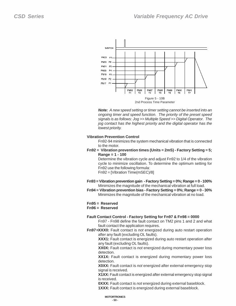
CSD Series Variable Frequency AC Drive
MOTORTRONICS- 50 -
Note: A new speed setting or timer setting cannot be inserted into anongoing timer and speed function. The priority of the preset speedsignals is as follows: Jog >> Multiple Speed >> Digital Operator. Thejog contact has the highest priority and the digital operator has thelowest priority.
Vibration Prevention ControlFn92-94 minimizes the system mechanical vibration that is connectedto the motor.
Fn92 = Vibration prevention times (Units = 2mS) - Factory Setting = 5;Range = 1 - 100Determine the vibration cycle and adjust Fn92 to 1/4 of the vibrationcycle to minimize oscillation. To determine the optimum setting forFn92 use the following formula:Fn92 = [Vibration Time(mSEC)/8]
Fn93 = Vibration prevention gain - Factory Setting = 0%; Range = 0 - 100%Minimizes the magnitude of the mechanical vibration at full load.
Fn94 = Vibration prevention bias - Factory Setting = 0%; Range = 0 - 30%Minimizes the magnitude of the mechanical vibration at no load.
Fn95 = ReservedFn96 = Reserved
Fault Contact Control - Factory Setting for Fn97 & Fn98 = 0000Fn97 - Fn98 define the fault contact on TM2 pins 1 and 2 and whatfault contact the application requires.
Fn97 = XXX0: Fault contact is not energized during auto restart operationafter any fault (excluding OL faults).XXX1: Fault contact is energized during auto restart operation afterany fault (excluding OL faults).XX0X: Fault contact is not energized during momentary power lossdetection.XX1X: Fault contact is energized during momentary power lossdetection.X0XX: Fault contact is not energized after external emergency stopsignal is received.X1XX: Fault contact is energized after external emergency stop signalis received.0XXX: Fault contact is not energized during external baseblock.1XXX: Fault contact is energized during external baseblock.
Figure 5 - 10B2nd Process Time Parameter
CSD Series Variable Frequency AC Drive
MOTORTRONICS- 51 -
Fn98: XXX0: Fault contact is not energized after overtorque (OL3) is detected.XXX1: Fault contact is energized after overtorque (OL3) is detectedXX0X: Fault contact is not energized after electronic thermal motorprotection (OL1) is acting.XX1X: Fault contact is energized after electronic thermal motorprotection (OL1) is acting.X0XX: Fault contact is normal open (N.O.).X1XX: Fault contact is normal closed (N.C.).0XXX: Fault contact is not energized after electronic thermal driveprotection (OL2) is acting1XXX: Fault contact is energized after electronic thermal driveprotection (OL2) is acting
Fn99: Reserved
Communication ModeFn100 - Fn102 define the communication parameters of the drive.
Fn100 = Communication identification number - Factory Setting = 1;Range = 1 - 32Fn100 provides an identification number to each individual drive forcommunications. When using more than one drive in acommunications loop, ensure that each individual drive has a uniqueidentification number programmed into Fn100. Having more than onedrive in a communications loop with the same ID number will causecommunications conflicts.
Fn101 = Baud rate of communication - Factory Setting = 1; Range = 0/1/2 (4800/9600/19200)
Fn101 defines the baud rate of communication between drives and thehost computer. Ensure that all devices in a communication loop areprogrammed to the same baud rate.
Fn102 = Communication agreement - Factory Setting = 1100; Range =XXX0: 1 stop bitXXX1: 2 stop bitsXX0X: Even parityXX1X: Odd parityX0XX: Without parityX1XX: With parity0XXX: 8 bits data1XXX: 7 bits dataFn102 defines for the drive the characteristic of the communicationstring. There are basically two styles of communication that can beperformed with the drive. Using the RS485 Kit, up to 32 drives can beconnected to one host computer for control. Using the RS232 Kit, onedrive can be connected to a host computer for both control andprogramming functions. Software exists for both modes using astandard PC as the host computer. If the application requires customprogramming, copies of the drive protocol can be obtained fromMotortronics
Fn103 - Fn122 = Reserved
CSD Series Variable Frequency AC Drive
MOTORTRONICS- 52 -
Fn123 = 1111: Revert to Factory SettingThe parameters of the drive can be set back to factory settings (withthe exception of Fn0, 5, 6, 30, 100-106, 124) by programming Fn123= 1111.
Fn124 = CPU VersionThe CPU version is factory set. Do not change this information.
Fn125 = Fault Sequence ReferenceTo assist in troubleshooting, the drive remembers the last three faultcodes automatically in its EEPROM memory. Once in Fn125,depressing the increase (∆) and decrease (∇) keys on the keypad willdisplay the last three faults recorded. Refer to the fault code indicationin this manual for an explanation of possible causes of these faultsand possible solutions.
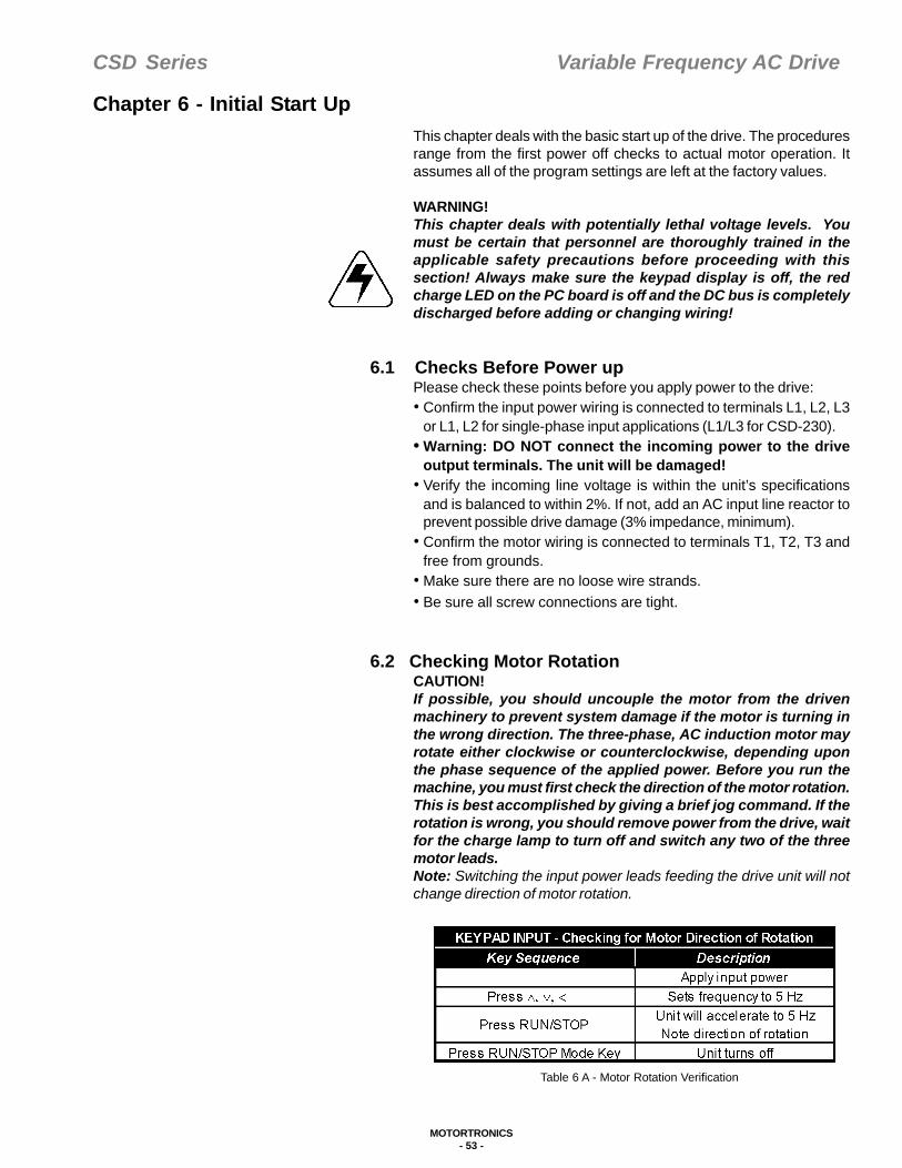
CSD Series Variable Frequency AC Drive
MOTORTRONICS- 53 -
Table 6 A - Motor Rotation Verification
This chapter deals with the basic start up of the drive. The proceduresrange from the first power off checks to actual motor operation. Itassumes all of the program settings are left at the factory values.
WARNING!This chapter deals with potentially lethal voltage levels. Youmust be certain that personnel are thoroughly trained in theapplicable safety precautions before proceeding with thissection! Always make sure the keypad display is off, the redcharge LED on the PC board is off and the DC bus is completelydischarged before adding or changing wiring!
6.1 Checks Before Power upPlease check these points before you apply power to the drive:• Confirm the input power wiring is connected to terminals L1, L2, L3
or L1, L2 for single-phase input applications (L1/L3 for CSD-230).• Warning: DO NOT connect the incoming power to the drive
output terminals. The unit will be damaged!• Verify the incoming line voltage is within the unit’s specifications
and is balanced to within 2%. If not, add an AC input line reactor toprevent possible drive damage (3% impedance, minimum).
• Confirm the motor wiring is connected to terminals T1, T2, T3 andfree from grounds.
• Make sure there are no loose wire strands.• Be sure all screw connections are tight.
6.2 Checking Motor RotationCAUTION!If possible, you should uncouple the motor from the drivenmachinery to prevent system damage if the motor is turning inthe wrong direction. The three-phase, AC induction motor mayrotate either clockwise or counterclockwise, depending uponthe phase sequence of the applied power. Before you run themachine, you must first check the direction of the motor rotation.This is best accomplished by giving a brief jog command. If therotation is wrong, you should remove power from the drive, waitfor the charge lamp to turn off and switch any two of the threemotor leads.Note: Switching the input power leads feeding the drive unit will notchange direction of motor rotation.
Chapter 6 - Initial Start Up

CSD Series Variable Frequency AC Drive
MOTORTRONICS- 54 -
6.3 Keypad OperationAfter the direction of motor rotation isverified you are ready to operate the driveunit from the keypad. The example inFigure 6 -1 explains the keypadoperation.
*Display will blink in the stop mode.
Enabling potentiometer on keypad;(The potentiometer on the keypad canbe used to control frequency byprogramming Fn11 = 0001.)
6.4 Programming Terminal StripOperationIf the keypad operation is satisfactory,you are ready to operate from the keypador switch to terminal strip (remote)control of the unit. To do this you willneed to change the following settings:• Fn10 = 1: for terminal strip start/stop
run control• Fn11 = 2: for terminal strip signal
reference control
Even though you can separate thesefunctions to have partial control at theterminal strip and partial control at thekeypad, the programming exampleshown in Table 6 B assumes you willcontrol both the reference and the run/stop from the terminal strip.
Table 6 B - Terminal Strip Power Control
1. Apply AC power. After a five second power upthe display will indicate as shown.
2. Press to run motor and display outputfrequency.
3. Press scroll to the left to select each of the four digits for the
required speed. (Active digit willblink)
Press to set each of the four digitsfor the desired speed.
4. Press to enter the data into the drive. This will cause themotor to accelerate to thedesired speed.
5. Press to decelerate to zero speedand accelerate up to setspeed in the opposite direction.
6. Press to decelerate to zero speedand accelerate to set speed inthe forward direction.
7. Press to decelerate to zero speedand stop the motor.
DisplayExample
Keypad Start-up
25.00
25.00
05.00
05.00
25.00
25.00
25.00
RUNSTOP
RESET<
READENTER
FWD
REV
FWD
REV
RUN
STOP
*
*
u
u
Figure 6 - 1Keypad Operation
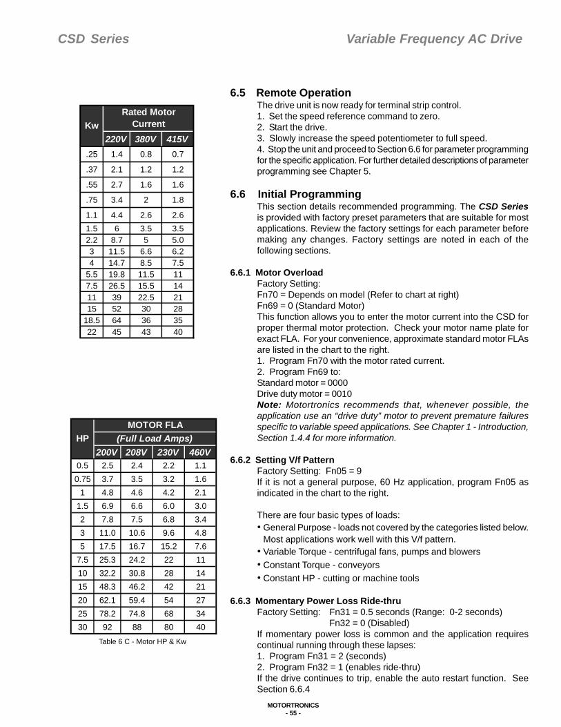
CSD Series Variable Frequency AC Drive
MOTORTRONICS- 55 -
Table 6 C - Motor HP & Kw
6.5 Remote OperationThe drive unit is now ready for terminal strip control.1. Set the speed reference command to zero.2. Start the drive.3. Slowly increase the speed potentiometer to full speed.4. Stop the unit and proceed to Section 6.6 for parameter programmingfor the specific application. For further detailed descriptions of parameterprogramming see Chapter 5.
6.6 Initial ProgrammingThis section details recommended programming. The CSD Seriesis provided with factory preset parameters that are suitable for mostapplications. Review the factory settings for each parameter beforemaking any changes. Factory settings are noted in each of thefollowing sections.
6.6.1 Motor OverloadFactory Setting:Fn70 = Depends on model (Refer to chart at right)Fn69 = 0 (Standard Motor)This function allows you to enter the motor current into the CSD forproper thermal motor protection. Check your motor name plate forexact FLA. For your convenience, approximate standard motor FLAsare listed in the chart to the right.1. Program Fn70 with the motor rated current.2. Program Fn69 to:Standard motor = 0000Drive duty motor = 0010Note: Motortronics recommends that, whenever possible, theapplication use an “drive duty” motor to prevent premature failuresspecific to variable speed applications. See Chapter 1 - Introduction,Section 1.4.4 for more information.
6.6.2 Setting V/f PatternFactory Setting: Fn05 = 9If it is not a general purpose, 60 Hz application, program Fn05 asindicated in the chart to the right.
There are four basic types of loads:• General Purpose - loads not covered by the categories listed below.
Most applications work well with this V/f pattern.• Variable Torque - centrifugal fans, pumps and blowers• Constant Torque - conveyors• Constant HP - cutting or machine tools
6.6.3 Momentary Power Loss Ride-thruFactory Setting: Fn31 = 0.5 seconds (Range: 0-2 seconds)
Fn32 = 0 (Disabled)If momentary power loss is common and the application requirescontinual running through these lapses:1. Program Fn31 = 2 (seconds)2. Program Fn32 = 1 (enables ride-thru)If the drive continues to trip, enable the auto restart function. SeeSection 6.6.4
200V 208V 230V 460V0.5 2.5 2.4 2.2 1.10.75 3.7 3.5 3.2 1.6
1 4.8 4.6 4.2 2.11.5 6.9 6.6 6.0 3.02 7.8 7.5 6.8 3.43 11.0 10.6 9.6 4.85 17.5 16.7 15.2 7.6
7.5 25.3 24.2 22 1110 32.2 30.8 28 1415 48.3 46.2 42 2120 62.1 59.4 54 2725 78.2 74.8 68 3430 92 88 80 40
HPMOTOR FLA
(Full Load Amps)
220V 380V 415V.25 1.4 0.8 0.7
.37 2.1 1.2 1.2
.55 2.7 1.6 1.6
.75 3.4 2 1.8
1.1 4.4 2.6 2.61.5 6 3.5 3.52.2 8.7 5 5.03 11.5 6.6 6.24 14.7 8.5 7.5
5.5 19.8 11.5 117.5 26.5 15.5 1411 39 22.5 2115 52 30 28
18.5 64 36 3522 45 43 40
KwRated Motor
Current

CSD Series Variable Frequency AC Drive
MOTORTRONICS- 56 -
Figure 6 - 2 Function of Jumper (Shorting Pants)
1
2
3
1
2
3
1
2
3
1
2
3
1
2
3
1
2
3
1
2
3
1
2
3
Table 6 D - Type of Load
6.6.4 Auto Restart After Fault TripFactory Setting: Fn16 = 0000 (Restart disabled)
Fn34 = 0 (Restart interval. Range: 0-800 sec.)Fn35 = 0 (Number of attempts. Range: 0-10)
The unit can be programed to automatically attempt a restart after afault condition.Example:1. Program Fn16 = 0010 (Restart enabled. See warning)2. Program Fn34 = 2 (2 second interval)3. Program Fn35 = 10 (10 tries)
6.6.5 Reset Parameters to Factory SettingsFactory Setting: Fn123 = 0000The unit can be reset to factory settings by programming Fn123 =1111.
Note: The following parameter settings are not affected by a reset tofactory settings:Fn00 = Factory use onlyFn05 = V/f pattern (see section 4.2)Fn06 = Frequency output upper limit (factory set at 60 Hz. See section5.3 page 30)Fn30 = Supply voltage (factory set depending on the unit rating)Fn100 - 106 and Fn124 = Communications (ID, baud rate, etc.)
6.6.6 Voltage of Power SupplyFn30: Adjust Fn30 to reflect the power supply voltage
6.7 Jumper Selection for Analog Frequency SignalChange the jumper position as required for the type of analog signal.(See page 18 for jumper location)1. 0-5 VDC or Potentiometer control, shorting pants on JP1 Pin 1and 22. 4 -20 mA control, shorting pants on JP1 Pins 2 and 33. 0 - 10 VDC control, shorting pants on JP2 Pins 2 and 3
If the Auto Restart feature isenabled, it is strongly recommendedthat warning stickers be placed onthe drive and in the operating areaindicating that the equipment mayautomatically start!
Warning!
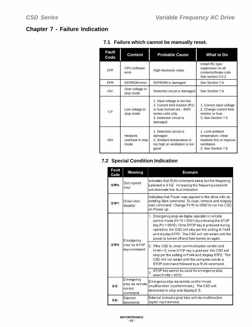
CSD Series Variable Frequency AC Drive
MOTORTRONICS- 57 -
Chapter 7 - Failure Indication
7.1 Failure which cannot be manually reset.
7.2 Special Condition Indication
FaultCode Content Probable Cause What to Do
CPF CPU software error High electronic noise
Install RC type suppressor on all contactor/brake coilsSee section 3.5.2
EPR EEPROM error EEPROM is damaged See Section 7.6
-OV- Over voltage in stop mode Detection circuit is damaged See Section 7.6
-LV- Low voltage in stop mode
1. Input voltage is too low2. Current limit resistor (R1) or fuse burned out - 400V series units only3. Detection circuit is damaged
1. Correct input voltage2. Change current limit resistor or fuse3. See Section 7.6
-OH-Heatsink overheat in stop mode
1. Detection circuit is damaged2. Ambient temperature is too high or ventilation is not good
1. Limit ambient temperature, clean heatsink fins or improve ventilation2. See Section 7.6

CSD Series Variable Frequency AC Drive
MOTORTRONICS- 58 -
7.3 Failure which can be auto reset or manually reset.
Note: When braking resistor is overloaded during deceleration, the drivewill stop braking and will display OH1. When heat is dissipated, OH1will disappear and the drive will start braking again.
7.4 Failure which can be manually reset, but cannot be autoreset.
Fault Code Meaning Probable Cause What to do
-OC- Over current during stop mode Detecting circuit failure 1. Set Fn12 = 0000
2. See Section 7.6
OL1 Motor overload
1. Excessive load2. Incorrect V/f pattern selection3. Incorrect motor FLA current selection
1. Select a larger HP unit2. Select correct V/f pattern3. Program correct motor FLA in drive
OL2 Drive overload 1. Excessive load2. Incorrect V/f pattern selection
1. Select a larger HP unit2. Select correct V/f pattern
OL3 Overtorque 1. Excessive load2. Incorrect V/f pattern selection
1. Select a larger HP unit2. Select correct V/f pattern
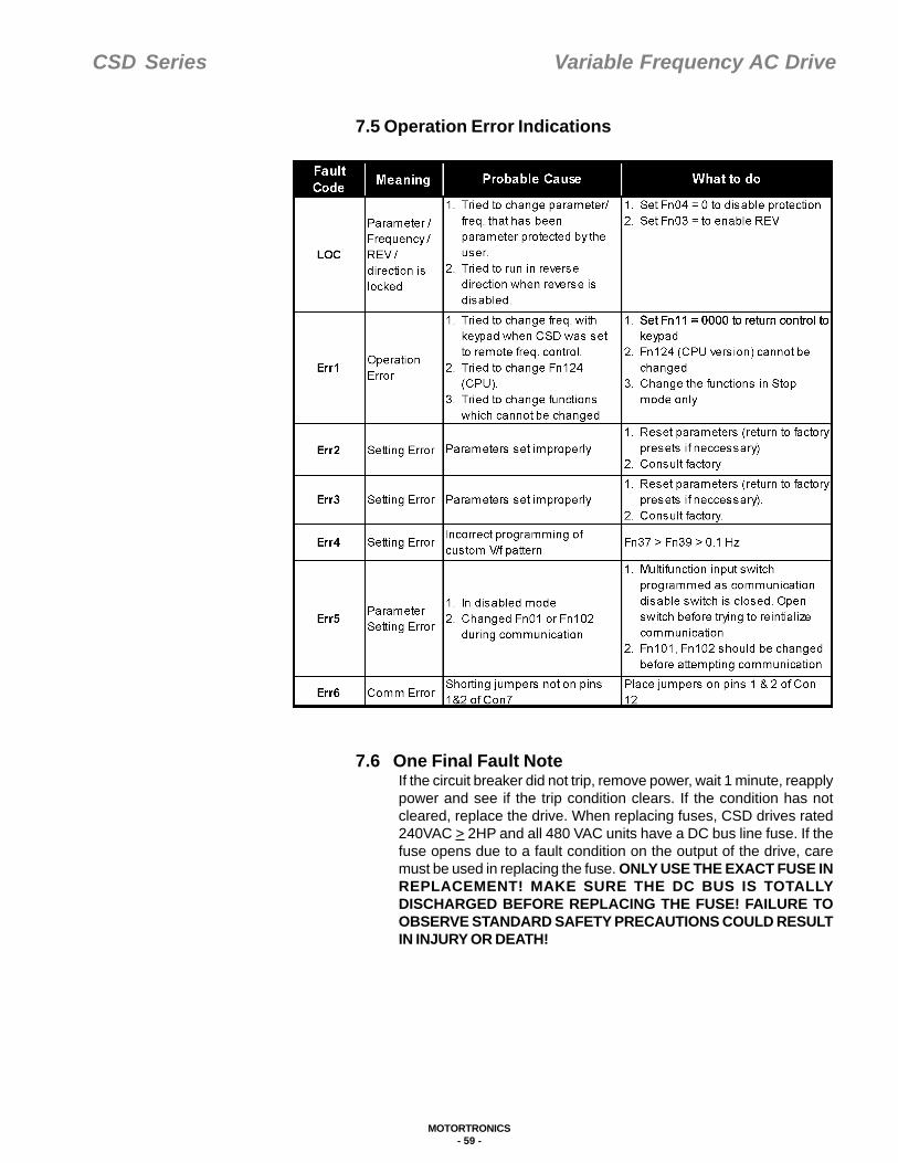
CSD Series Variable Frequency AC Drive
MOTORTRONICS- 59 -
7.5 Operation Error Indications
7.6 One Final Fault NoteIf the circuit breaker did not trip, remove power, wait 1 minute, reapplypower and see if the trip condition clears. If the condition has notcleared, replace the drive. When replacing fuses, CSD drives rated240VAC > 2HP and all 480 VAC units have a DC bus line fuse. If thefuse opens due to a fault condition on the output of the drive, caremust be used in replacing the fuse. ONLY USE THE EXACT FUSE INREPLACEMENT! MAKE SURE THE DC BUS IS TOTALLYDISCHARGED BEFORE REPLACING THE FUSE! FAILURE TOOBSERVE STANDARD SAFETY PRECAUTIONS COULD RESULTIN INJURY OR DEATH!

CSD Series Variable Frequency AC Drive
MOTORTRONICS- 60 -
Chapter 8 - Troubleshooting
8.1 General TroubleshootingIf the drive malfunctions, find the cause and take the corrective actionsby following the flowcharts. If the cause cannot be located in theflowcharts contact MOTORTRONICS.
8.2 Power Section Troubleshooting
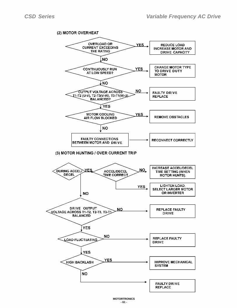
CSD Series Variable Frequency AC Drive
MOTORTRONICS- 61 -
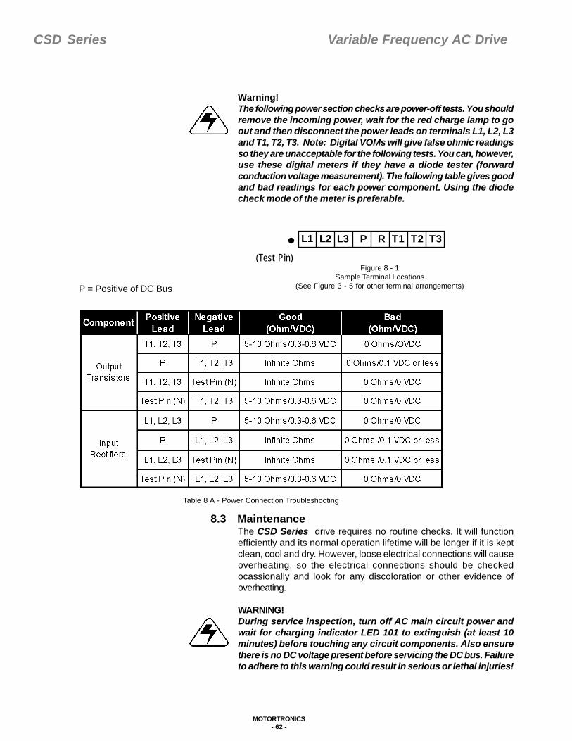
CSD Series Variable Frequency AC Drive
MOTORTRONICS- 62 -
L1 L2 L3 P R T1 T2 T3
Table 8 A - Power Connection Troubleshooting
P = Positive of DC Bus
Figure 8 - 1Sample Terminal Locations
(See Figure 3 - 5 for other terminal arrangements)
(Test Pin)
Warning!The following power section checks are power-off tests. You shouldremove the incoming power, wait for the red charge lamp to goout and then disconnect the power leads on terminals L1, L2, L3and T1, T2, T3. Note: Digital VOMs will give false ohmic readingsso they are unacceptable for the following tests. You can, however,use these digital meters if they have a diode tester (forwardconduction voltage measurement). The following table gives goodand bad readings for each power component. Using the diodecheck mode of the meter is preferable.
8.3 MaintenanceThe CSD Series drive requires no routine checks. It will functionefficiently and its normal operation lifetime will be longer if it is keptclean, cool and dry. However, loose electrical connections will causeoverheating, so the electrical connections should be checkedocassionally and look for any discoloration or other evidence ofoverheating.
WARNING!During service inspection, turn off AC main circuit power andwait for charging indicator LED 101 to extinguish (at least 10minutes) before touching any circuit components. Also ensurethere is no DC voltage present before servicing the DC bus. Failureto adhere to this warning could result in serious or lethal injuries!

CSD Series Variable Frequency AC Drive
MOTORTRONICS- 63 -
8.3.1 Mega TestCheck for tightness of electrical connections, discoloration or othersigns of overheating. During service inspection, turn off AC main circuitpower and wait for charging indicator LED 101 to extinguish (or atleast 10 minutes) before touching any circuit components. Failure toadhere to this warning could result in serious or lethal injuries.
1. Clean up internal dust and dirt2.Check for tightness of electrical connections.3. Do Mega test
a. Remove all connection wires from the complete unit when doingthe Mega test.
b. Connect all T & L leads together with jumper wire.c. Mega test can only be applied on main circuit.
Note: Never do the Mega Test on control circuit. Theinsulation resistance of DC500V tester should be more than5M ohm after completing this test.
d. After completing test, remove jumpers installed in step (b). e. Reconnect all removed wires in step (a).
8.3.2 Ground Fault Protection When Motor is RunningIf a “ground fault” occurs while motor is running, transient surge currentswill destroy the power section of CSD. The CSD offers an optionalground fault protection unit to detect the surge current and disable theoutput section whenever ground fault occurs.Installation:
1. Disconnect the CSD from power source.2. Make sure that charge lamp (LED 101) extinguishes and wait for
at least 10 minutes before taking next step.3. Thread output line (T1, T2, T3) through ground fault current
transformer and connect ground faulT current to CON 4 (as shownon diagram).
4. Be sure to thread all T1, T2 and T3 through ground Fault currenttransformer.
*Max cross section of T1, T2 and T3 should < 7mm.
Note: Ground fault is standard on 230V, 5Hp and above, on 460V,7Hp and above, and on all 600V units.
8.3.3 Fuse ReplacementCSD drives with 240VAC > 2 HP and all 480 VAC have a DC Bus linefuse. If the fuse opens due do a fault condition on the output of thedrive, care must be used in replacing the fuse. ONLY USE THE EXACTFUSE IN REPLACEMENT! MAKE SURE THE DC BUS IS TOTALLYDISCHARGED BEFORE REPLACING THE FUSE! FAILURE TOOBSERVE STANDARD SAFETY PRECAUTIONS COULD RESULTINJURY OR DEATH! Once the DC fuse is replaced, perform the troubleshooting procedures in Section 8.2 prior to energizing the drive.
Figure 8 - 2Mega Test
Figure 8 - 3Ground Fault Connections

CSD Series Variable Frequency AC Drive
MOTORTRONICS- 64 -
Chapter 9 - Reference
9.1 Measurement of Voltage and CurrentThe procedure for measuring Primary and Secondary voltage and current willbe somewhat different for VFD's because of the variety of measuringinstruments and high harmonic content of the waveform. Refer to the followingillustration for measurement techniques.
Figure 9-1 - Measuring Volage and Current
9.2 Electromagnetic Compatibility of AC DrivesSimilar to all modern PWM variable speed drives the CSD Series AC Drivesuses fast switching of high voltage and currents to achieve high efficiencyand reduced motor acoustic noise. This results in electromagnetic interference(EMI) and radio frequency interference (RFI) that occurs at the switchingfrequency and harmonics of this frequency. The amount of interference isdependent on the amount of current the drive delivers to the load. Foroperational reasons the interference may need to be suppressed. As EMIand RFI can involve very complex coupling modes, not all solutions can beeasily found.• Practical solutions include:• Mounting sensitive equipment at a distance from the drives.• Providing screening and grounding on all cables, the drive motor
and enclosure.• Putting filters on the input and output sides of the drive.
Table 9 A - Testing for Voltage and Current
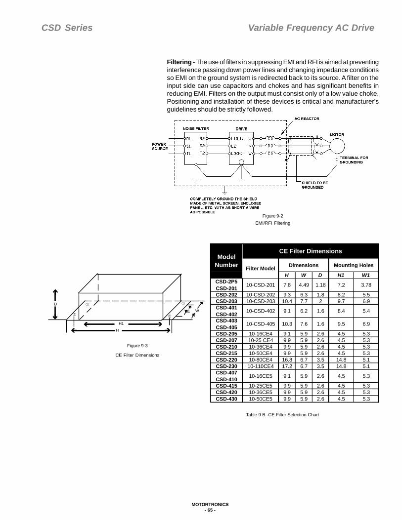
CSD Series Variable Frequency AC Drive
MOTORTRONICS- 65 -
H1H
WW1
D
Filtering - The use of filters in suppressing EMI and RFI is aimed at preventinginterference passing down power lines and changing impedance conditionsso EMI on the ground system is redirected back to its source. A filter on theinput side can use capacitors and chokes and has significant benefits inreducing EMI. Filters on the output must consist only of a low value choke.Positioning and installation of these devices is critical and manufacturer'sguidelines should be strictly followed.
Figure 9-2EMI/RFI Filtering
Figure 9-3
CE Filter Dimensions
Table 9 B -CE Filter Selection Chart
H W D H1 W1CSD-2P5 CSD-201 10-CSD-201 7.8 4.49 1.18 7.2 3.78
CSD-202 10-CSD-202 9.3 6.3 1.8 8.2 5.5CSD-203 10-CSD-203 10.4 7.7 2 9.7 6.9CSD-401 CSD-402 10-CSD-402 9.1 6.2 1.6 8.4 5.4
CSD-403 CSD-405 10-CSD-405 10.3 7.6 1.6 9.5 6.9
CSD-205 10-16CE4 9.1 5.9 2.6 4.5 5.3CSD-207 10-25 CE4 9.9 5.9 2.6 4.5 5.3CSD-210 10-36CE4 9.9 5.9 2.6 4.5 5.3CSD-215 10-50CE4 9.9 5.9 2.6 4.5 5.3CSD-220 10-80CE4 16.8 6.7 3.5 14.8 5.1CSD-230 10-110CE4 17.2 6.7 3.5 14.8 5.1CSD-407 CSD-410 10-16CE5 9.1 5.9 2.6 4.5 5.3
CSD-415 10-25CE5 9.9 5.9 2.6 4.5 5.3CSD-420 10-36CE5 9.9 5.9 2.6 4.5 5.3CSD-430 10-50CE5 9.9 5.9 2.6 4.5 5.3
Model Number Filter Model
CE Filter Dimensions
Mounting HolesDimensions

CSD Series Variable Frequency AC Drive
MOTORTRONICS- 66 -
Grounding - It is very important that effective EMI and RFI grounding beprovided. EMI and RFI grounding provide a low HF impedance to earth.This differs from standard safety grounding that presents a relatively highimpedance to ground due to skin effect. Follow HF grounding procedureswhen making ground connections in these applications.Screening - The cable from the inverter to the motor should be screenedand solidly connected to both the inverter and motor using as much contactarea as possible. Mounting the inverter into an grounded metal enclosurewill also limit RFI. Guidelines for the positioning of filters, screening andgrounding are shown on the diagram.
9.3 AC Drive Model Number Definitions
Table 9 C - AC Drive Model Definitions
9.4 Extension Keypad Remote Cable There are two (2) keypad sizes for the CSD series inverters. Please seeTable 9 D for the appropriate extension keypad remote cable and then referto the corresponding assembly diagram.
Table 9 D - Compatible Keypads and Cables
Model number Fn-00CSD-2P5 01CSD-201 02CSD-202 03CSD-203 04CSD-505 05CSD-207 06CSD-210 07CSD-215 08CSD-220 09CSD-230 30CSD-401 10CSD402 11CSD403 12CSD-405 13CSD-407 14CSD-410 15CSD-415 16CSD420 17CSD-430 18
Model Matched Remote Cable Keypad
CSD-2P5 - CSD-205CSD-401- CSD-405CSD-207 - CSD-230CSD-407 - CSD-430
CSD W300X * NDOP-01
CSD W300XA * NDOP-02

CSD Series Variable Frequency AC Drive
MOTORTRONICS- 67 -
9.4.1Digital Operator Remote Cable Connection (CSDW300X) A. Plastic housing for digital operatorfront side 1rear side 3B. Digital Operator 2C. Remote cable 4
CSDW 3001 (1 meter)CSDW 3002 (2 meter)CSDW 3003 (3 meter)
D. Remote cable adapter 5E. Accessory screws 6, 7, 8• Turn off the power to the unit and verify that the power LED is
extinguished.• Remove the digital operator 2 and grounding wires (PE) from the
unit.• Place the digital operator 2 into plastic housing and then use
screw 8 to assemble the housing.• Put the remote cable adapter 5 into the unit.• Connect the remote cable terminal 4 to the digital operator, and
connect the grounding wire.• Connect the second remote cable terminal 9 to the remote cable adapter 5 and connect the grounding wire.• Use accessory screws 6 and 7 to attach the remote operator to the
panel.• Proper grounding on the unit is necessary to prevent interference.
(Grounding resistor must be less than 100 ohm, and the diameter ofthe grounding wire must be larger than 2mm2.)
Figure 9 - 4
CSD300X Connection

CSD Series Variable Frequency AC Drive
MOTORTRONICS- 68 -
9.4.2 Digital Operator Remote Cable Connection (CSDW 300XA)A. NDOP-02 Digital Operator 1B. Remote cable 2CSDW 3001 A (1 meter)CSDWW 3002 A (2 meter)CSDWW 3003 A (3 meter)C. Remote cable adapter 3D. Accessory screws 4
Turn off the power to the unit and verify that the power LED isextinguished.Remove the digital operator from unit. 1Place the remote cable adapter into the unit. 3Connect the both sides of the remote cable. 2Use accessory screws to attach the digital operator to the panel. 4
Figure 9 - 5
CSD300XA Connection
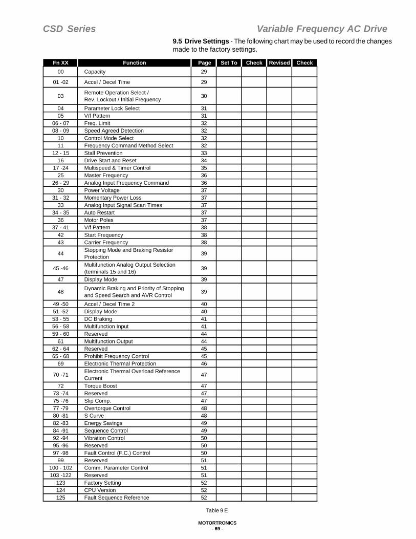
CSD Series Variable Frequency AC Drive
MOTORTRONICS- 69 -
Table 9 E
9.5 Drive Settings - The following chart may be used to record the changesmade to the factory settings.
Fn XX Function Page Set To Check Revised Check00 Capacity 29
01 -02 Accel / Decel Time 29
03 Remote Operation Select /Rev. Lockout / Initial Frequency 30
04 Parameter Lock Select 3105 V/f Pattern 31
06 - 07 Freq. Limit 3208 - 09 Speed Agreed Detection 32
10 Control Mode Select 3211 Frequency Command Method Select 32
12 - 15 Stall Prevention 3316 Drive Start and Reset 34
17 -24 Multispeed & Timer Control 3525 Master Frequency 36
26 - 29 Analog Input Frequency Command 3630 Power Voltage 37
31 - 32 Momentary Power Loss 3733 Analog Input Signal Scan Times 37
34 - 35 Auto Restart 3736 Motor Poles 37
37 - 41 V/f Pattern 3842 Start Frequency 3843 Carrier Frequency 38
44 Stopping Mode and Braking Resistor Protection 39
45 -46 Multifunction Analog Output Selection(terminals 15 and 16) 39
47 Display Mode 39
48 Dynamic Braking and Priority of Stopping and Speed Search and AVR Control 39
49 -50 Accel / Decel Time 2 4051 -52 Display Mode 4053 - 55 DC Braking 4156 - 58 Multifunction Input 4159 - 60 Reserved 44
61 Multifunction Output 4462 - 64 Reserved 4565 - 68 Prohibit Frequency Control 45
69 Electronic Thermal Protection 46
70 -71 Electronic Thermal Overload Reference Current 47
72 Torque Boost 4773 -74 Reserved 4775 -76 Slip Comp. 4777 -79 Overtorque Control 4880 -81 S Curve 4882 -83 Energy Savings 4984 -91 Sequence Control 4992 -94 Vibration Control 5095 -96 Reserved 5097 -98 Fault Control (F.C.) Control 50
99 Reserved 51100 - 102 Comm. Parameter Control 51103 -122 Reserved 51
123 Factory Setting 52124 CPU Version 52125 Fault Sequence Reference 52
CSD Series Variable Frequency AC Drive
MOTORTRONICS- 70 -
Prepared By: Date:
Set By: Date:
Received By: Date:

CSD Series Variable Frequency AC Drive
MOTORTRONICS- 71 -
Warranty Policy
Motortronics warrants its products to be free from defects in material and/orworkmanship for a period of one year from date of installation, to a maximumof 18 months from the date of shipment as indicated by the unit's date code.The Company reserves the right to repair or replace any malfunctioning unitsunder warranty at their option. All warranty repairs must be performed by theCompany factory, or on site by a factory authorized service firm or personnelapproved by the Company.
Solid state controls have different operation characteristics from those ofelectro-mechanical equipment. Because of these differences and the widevariety of applications for solid state controls, each application designer mustverify that the solid state equipment is acceptable for his application. In noevent will Motortronics be responsible or liable for indirect or consequentialdamages resulting from the use or application of this equipment. The diagramsand illustrations in this document are included solely for illustrative purposes.Because of the number of different applications, Motortronics cannot beresponsible or liable for actual use based on the examples or diagrams.
CSD Series Variable Frequency AC Drive
MOTORTRONICS- 72 -
1600 Sunshine Drive, Clearwater, FL USA 33765 Phone: 727.573.1819 or 888.767.7792 Fax: 727.573.1803 or 800.548.4104
E-mail: [email protected] www.motortronics.com
Related Documents