CS 408 Computer Networks Chapter 15 Local Area Networks

CS 408 Computer Networks Chapter 15 Local Area Networks.
Apr 02, 2015
Welcome message from author
This document is posted to help you gain knowledge. Please leave a comment to let me know what you think about it! Share it to your friends and learn new things together.
Transcript
CS 408Computer Networks
Chapter 15 Local Area Networks
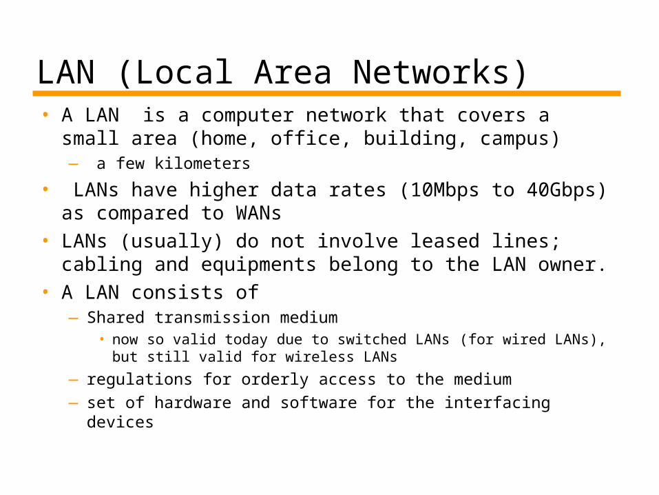
LAN (Local Area Networks)• A LAN is a computer network that covers a small
area (home, office, building, campus)— a few kilometers
• LANs have higher data rates (10Mbps to 40Gbps) as compared to WANs
• LANs (usually) do not involve leased lines; cabling and equipments belong to the LAN owner.
• A LAN consists of—Shared transmission medium
• now so valid today due to switched LANs (for wired LANs), but still valid for wireless LANs
— regulations for orderly access to the medium—set of hardware and software for the interfacing devices
LAN Protocol Architecture• Corresponds to lower two layers of OSI
model—But mostly LANs do not follow OSI model
• Current LANs are most likely to be based on Ethernet protocols developed by IEEE 802 committee
• IEEE 802 reference model—Logical link control (LLC)—Media access control (MAC)—Physical
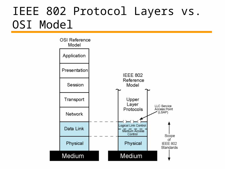
IEEE 802 Protocol Layers vs. OSI Model
IEEE 802 Layers - Physical• Signal encoding/decoding• Preamble generation/removal
—for synchronization
• Bit transmission/reception• Specification for topology and
transmission medium
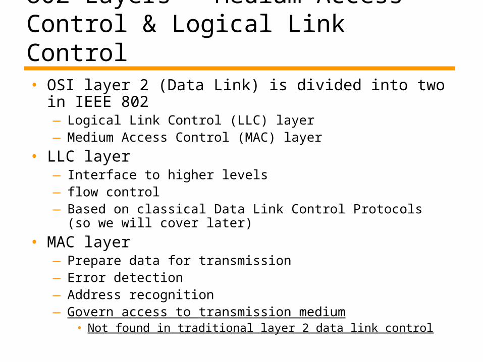
802 Layers - Medium Access Control & Logical Link Control• OSI layer 2 (Data Link) is divided into two in IEEE
802—Logical Link Control (LLC) layer —Medium Access Control (MAC) layer
• LLC layer—Interface to higher levels—flow control—Based on classical Data Link Control Protocols (so we
will cover later)
• MAC layer—Prepare data for transmission—Error detection—Address recognition—Govern access to transmission medium
• Not found in traditional layer 2 data link control
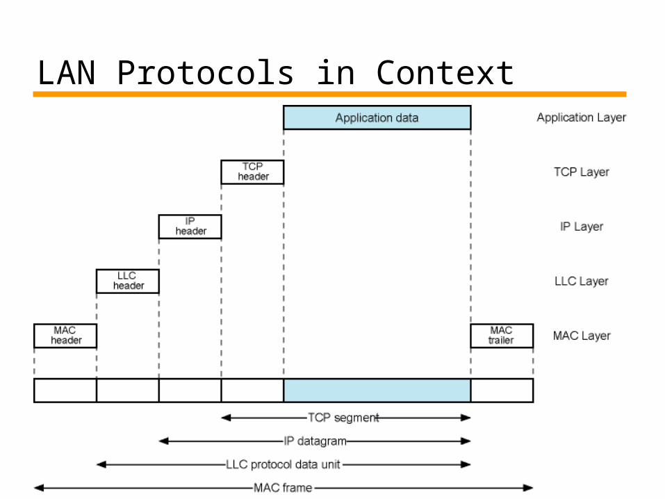
LAN Protocols in Context
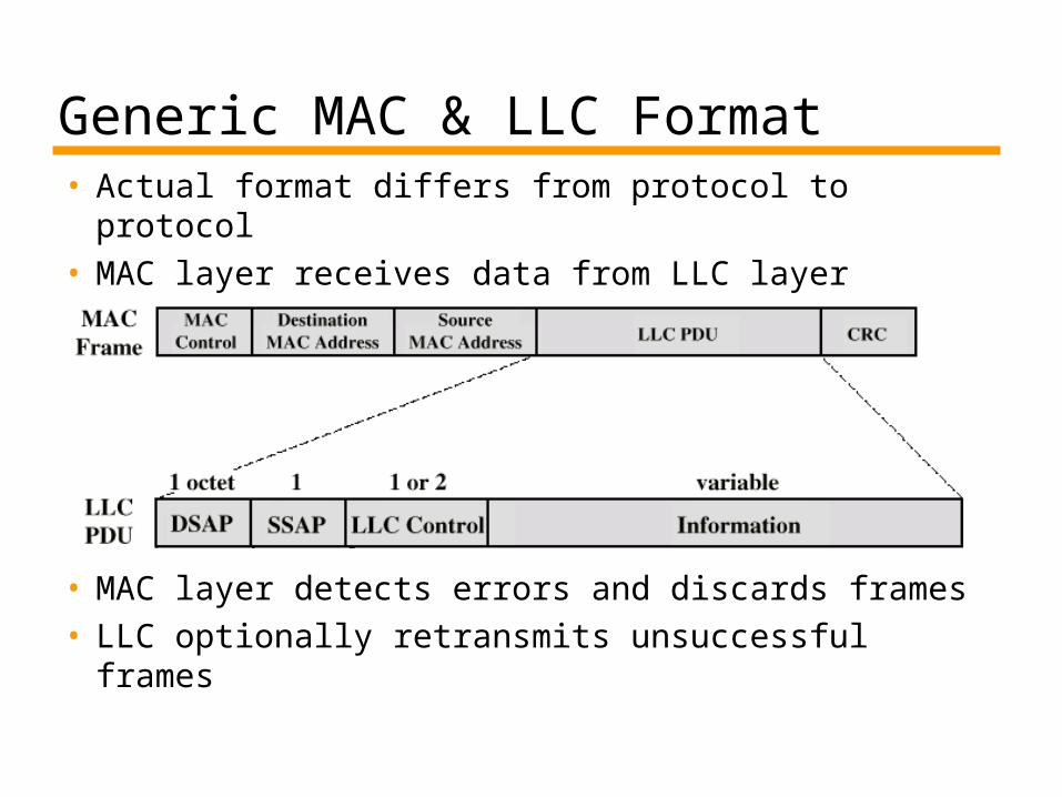
Generic MAC & LLC Format• Actual format differs from protocol to protocol• MAC layer receives data from LLC layer
• MAC layer detects errors and discards frames• LLC optionally retransmits unsuccessful
frames
LAN Topologies• Bus• Ring• Star
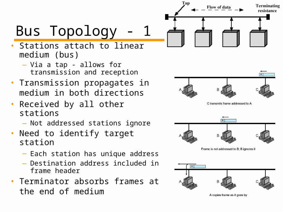
Bus Topology - 1• Stations attach to linear
medium (bus)—Via a tap - allows for
transmission and reception
• Transmission propagates in medium in both directions
• Received by all other stations—Not addressed stations ignore
• Need to identify target station—Each station has unique address —Destination address included in
frame header
• Terminator absorbs frames at the end of medium
Bus Topology - 2• Need to regulate transmission
—To avoid collisions• If two stations attempt to transmit at same time,
signals will overlap and become garbage—To avoid continuous transmission from a single station.
If one station transmits continuously, access is blocked for others
• Solution: Transmit Data in small blocks – frames
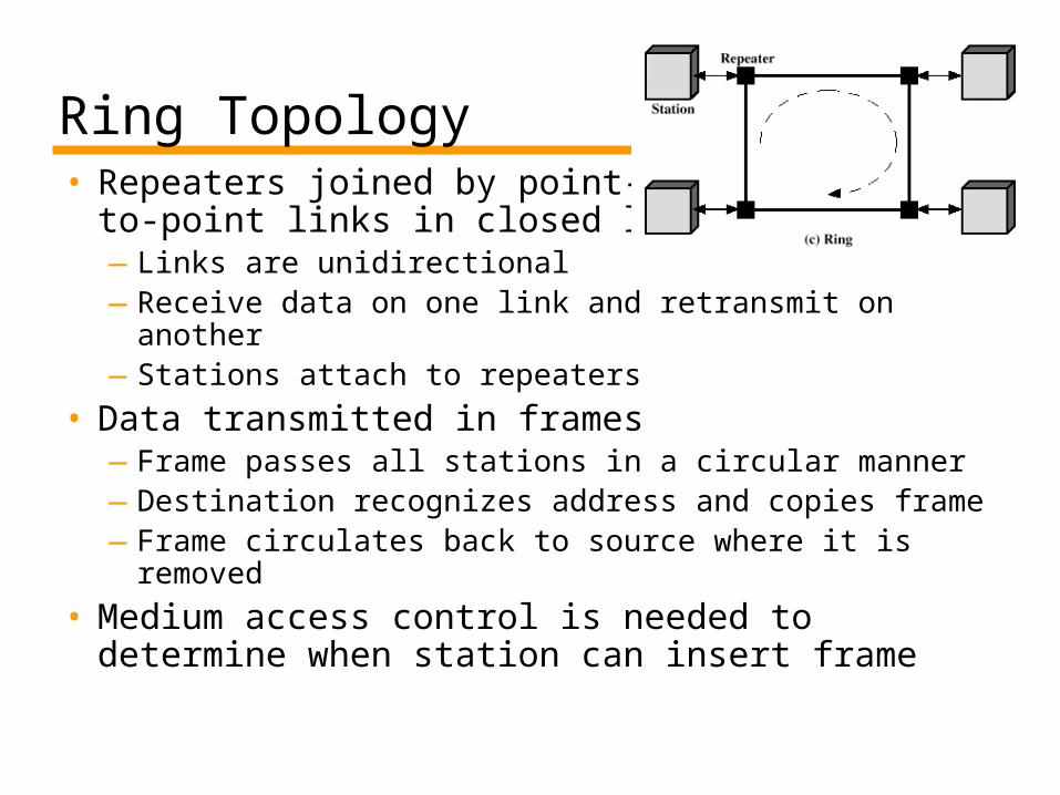
Ring Topology• Repeaters joined by point-
to-point links in closed loop—Links are unidirectional—Receive data on one link and retransmit on another—Stations attach to repeaters
• Data transmitted in frames—Frame passes all stations in a circular manner—Destination recognizes address and copies frame—Frame circulates back to source where it is
removed
• Medium access control is needed to determine when station can insert frame
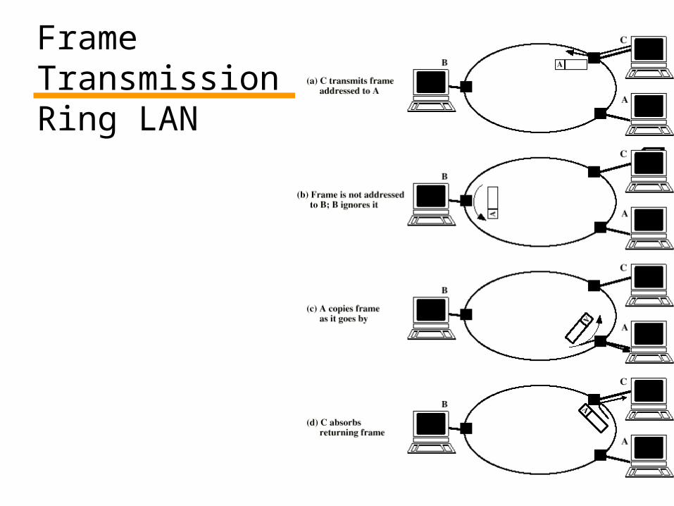
Frame TransmissionRing LAN
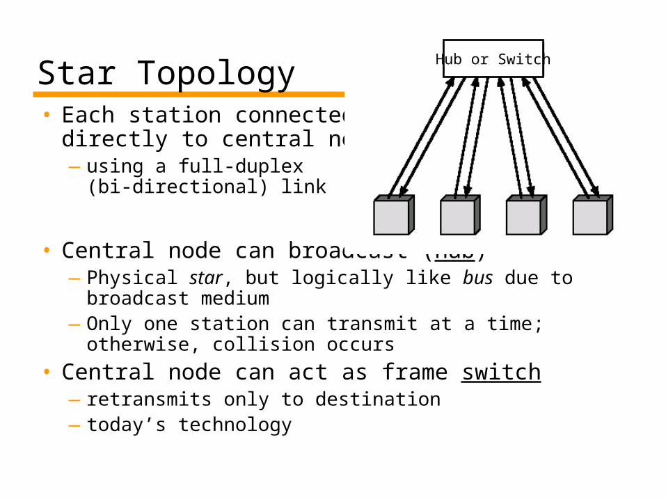
Star Topology• Each station connected
directly to central node—using a full-duplex
(bi-directional) link
• Central node can broadcast (hub)—Physical star, but logically like bus due to broadcast
medium—Only one station can transmit at a time; otherwise,
collision occurs
• Central node can act as frame switch—retransmits only to destination—today’s technology
Hub or Switch
Medium Access Control (MAC)• Traditionally, in LANs data is broadcast
—there is a single medium shared by different users
• We need MAC sublayer for—orderly and efficient use of broadcast medium
• This is actually a “channel allocation” problem
• Synchronous (static) solutions—everyone knows when to transmit
• Asynchronous (dynamic) solution—in response to immediate needs—Two categories
• Round robin• Contention
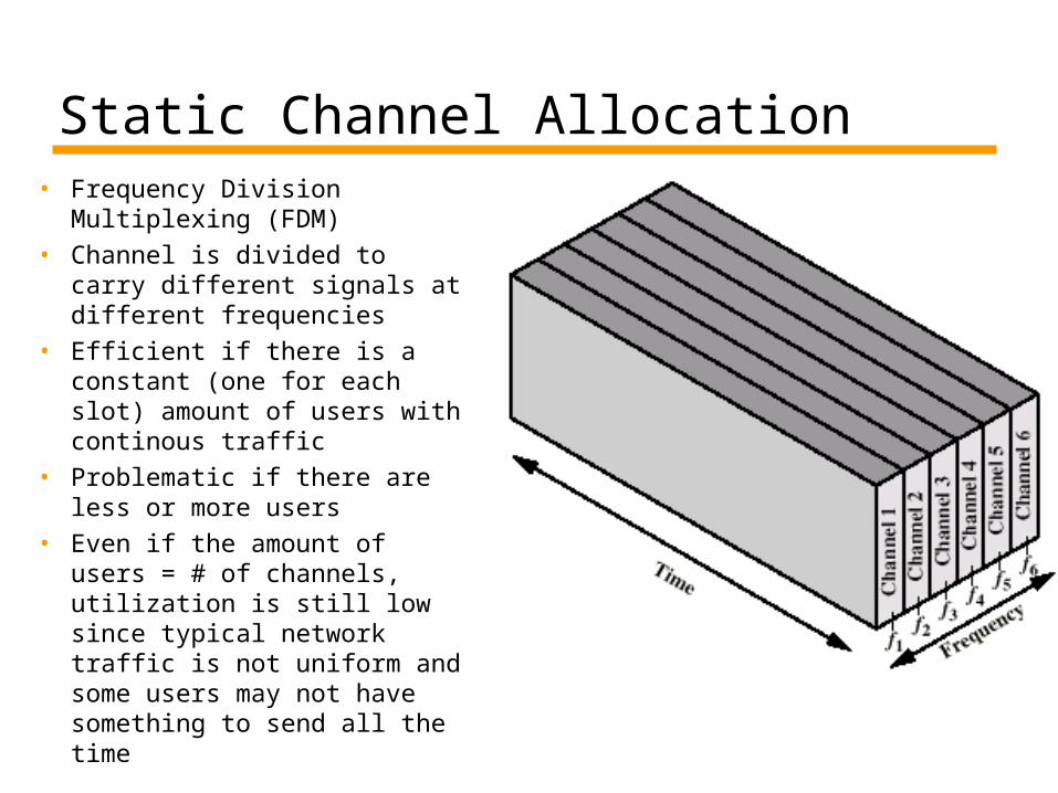
Static Channel Allocation• Frequency Division
Multiplexing (FDM)• Channel is divided to carry
different signals at different frequencies
• Efficient if there is a constant (one for each slot) amount of users with continous traffic
• Problematic if there are less or more users
• Even if the amount of users = # of channels, utilization is still low since typical network traffic is not uniform and some users may not have something to send all the time
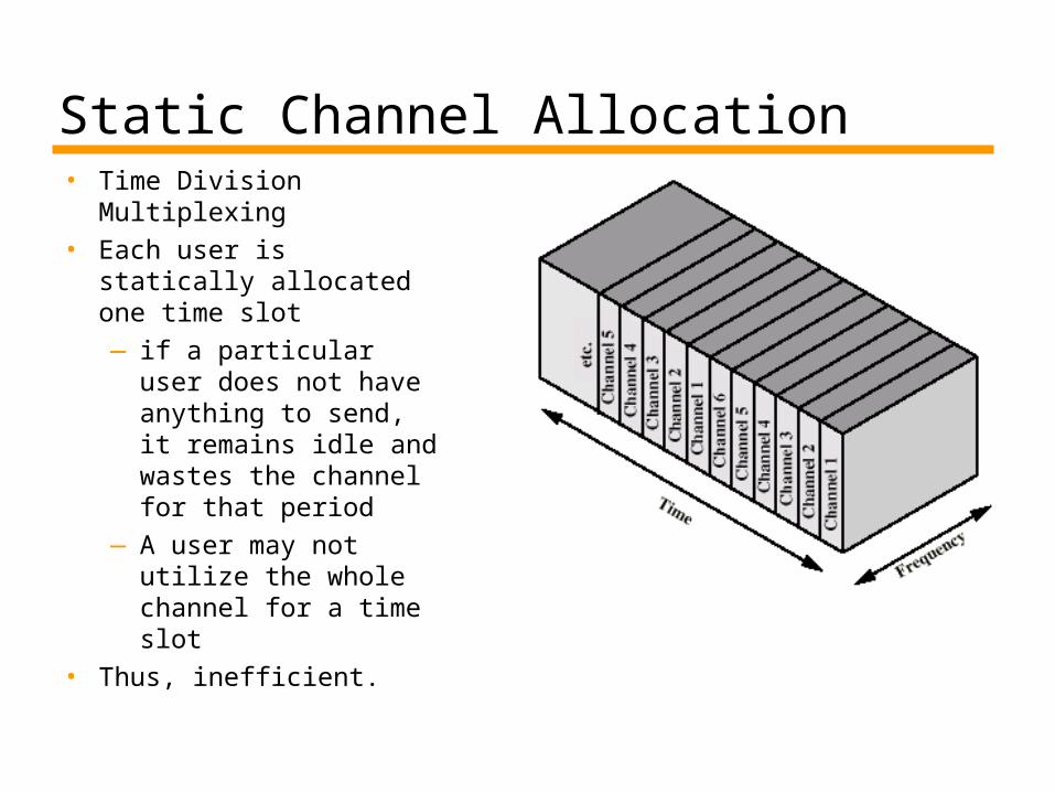
Static Channel Allocation• Time Division
Multiplexing• Each user is statically
allocated one time slot— if a particular user
does not have anything to send, it remains idle and wastes the channel for that period
—A user may not utilize the whole channel for a time slot
• Thus, inefficient.
Dynamic Channel Allocation Categories• Round robin
—each station has a turn to transmit• declines or transmits up to a certain data limit• overhead of passing the turn in either case
—Performs well if many stations have data to transmit for most of the time
• otherwise passing the turn would cause inefficiency
Dynamic Channel Allocation Categories• Contention
—All stations contend to transmit —No control to determine whose turn is it—Stations send data by taking risk of collision
(with others’ packets)• however they understand collisions by listening to
the channel, so that they can retransmit
—There are several implementation methods—In general, good for bursty traffic
• which is the typical traffic types for most networks
—Efficient under light or moderate load—Performance is bad under heavy load
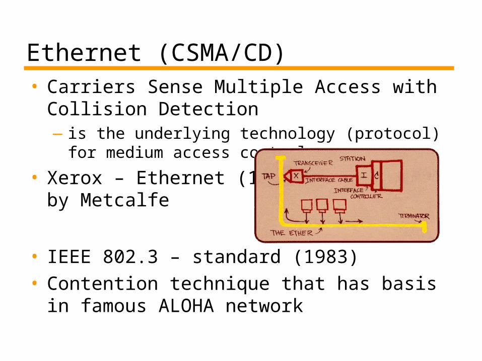
Ethernet (CSMA/CD)• Carriers Sense Multiple Access with
Collision Detection—is the underlying technology (protocol) for
medium access control
• Xerox – Ethernet (1976) by Metcalfe
• IEEE 802.3 – standard (1983)• Contention technique that has basis in
famous ALOHA network
ALOHA• Packet Radio (applicable to any shared medium)
— initially proposed to interconnect Hawaiian Islands (several stations)
• by Norman Abramson of Univ. of Hawaii (early 70s)• Later inspired the designers of Ethernet
• When station has frame, it sends—collisions may occur
• Station listens for max round trip time• If no collision, fine. If collision, retransmit after a
random waiting time—Collison is understood by listening or by having no
acknowledgement (two alternatives – see the notes of this slide)
• Max channel utilization is 18% - very bad
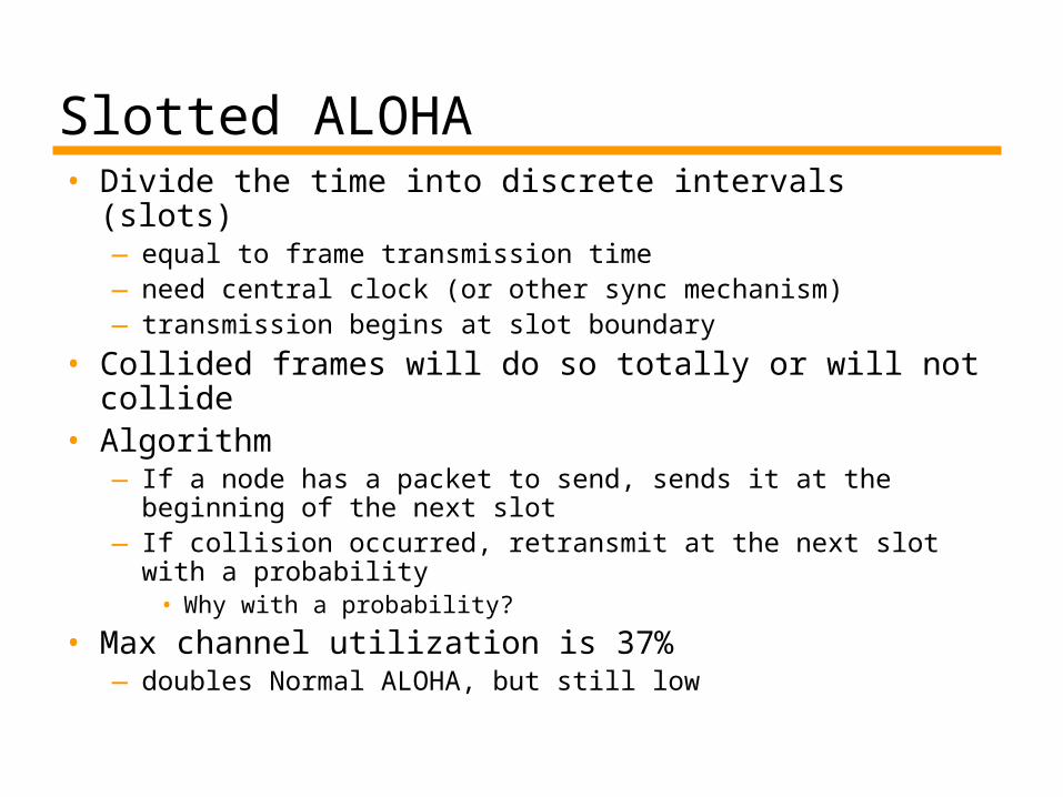
Slotted ALOHA• Divide the time into discrete intervals (slots)
—equal to frame transmission time—need central clock (or other sync mechanism)—transmission begins at slot boundary
• Collided frames will do so totally or will not collide
• Algorithm—If a node has a packet to send, sends it at the beginning
of the next slot—If collision occurred, retransmit at the next slot with a
probability• Why with a probability?
• Max channel utilization is 37%—doubles Normal ALOHA, but still low
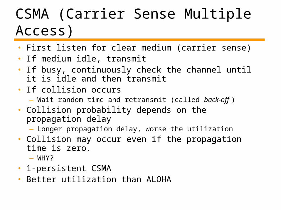
CSMA (Carrier Sense Multiple Access)• First listen for clear medium (carrier sense)• If medium idle, transmit• If busy, continuously check the channel until it is idle
and then transmit• If collision occurs
—Wait random time and retransmit (called back-off )
• Collision probability depends on the propagation delay—Longer propagation delay, worse the utilization
• Collision may occur even if the propagation time is zero. —WHY?
• 1-persistent CSMA• Better utilization than ALOHA
Nonpersistent CSMA• Patient CSMA• If channel idle, send• If not, do not continuously seize the
channel—instead wait a random period of time
• Better utilization, longer delay
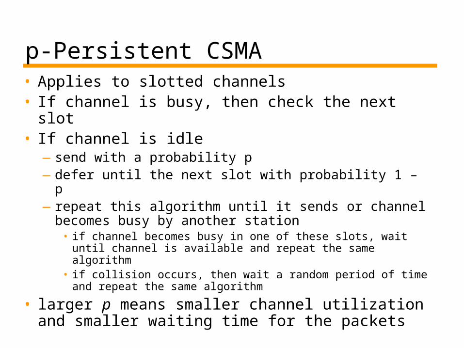
p-Persistent CSMA• Applies to slotted channels• If channel is busy, then check the next slot• If channel is idle
—send with a probability p—defer until the next slot with probability 1 – p—repeat this algorithm until it sends or channel
becomes busy by another station• if channel becomes busy in one of these slots, wait
until channel is available and repeat the same algorithm
• if collision occurs, then wait a random period of time and repeat the same algorithm
• larger p means smaller channel utilization and smaller waiting time for the packets
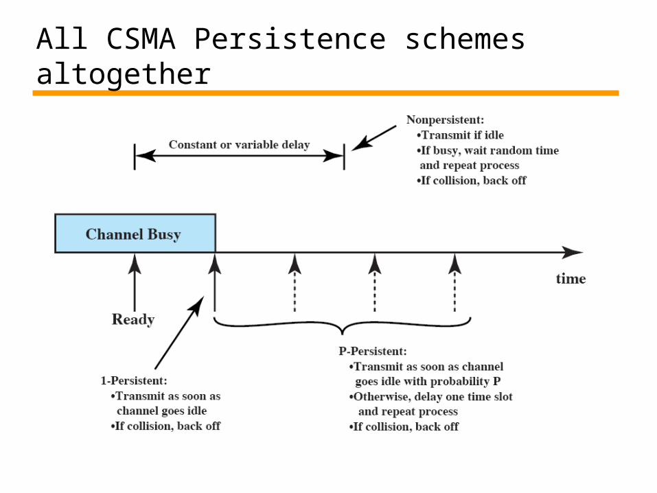
All CSMA Persistence schemes altogether
CSMA/CD (IEEE 802.3 – Ethernet)• As in 1-persistent CSMA, but uses slotted
channels—If medium idle, transmit—If busy, listen for idle slot, then transmit
• In regular CSMA, collision occupies medium for duration of transmission—it is inefficient to complete the transmission of a
collided packet
• In CSMA/CD, stations listen while transmitting • If collision detected (due to high voltage on
bus), cease transmission and wait random time then start again— random waiting time is determined using binary
exponential backoff mechanism
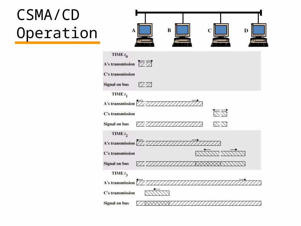
CSMA/CDOperation
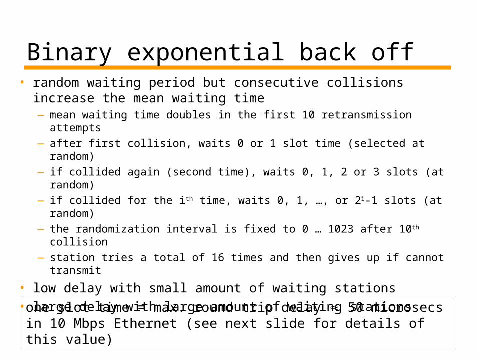
Binary exponential back off • random waiting period but consecutive collisions
increase the mean waiting time—mean waiting time doubles in the first 10 retransmission
attempts—after first collision, waits 0 or 1 slot time (selected at random)—if collided again (second time), waits 0, 1, 2 or 3 slots (at
random)—if collided for the ith time, waits 0, 1, …, or 2i-1 slots (at random)—the randomization interval is fixed to 0 … 1023 after 10th collision—station tries a total of 16 times and then gives up if cannot
transmit
• low delay with small amount of waiting stations• large delay with large amount of waiting stations
one slot time = max. round trip delay 50 microsecs in 10 Mbps Ethernet (see next slide for details of this value)
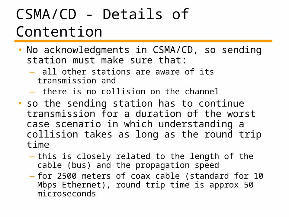
CSMA/CD - Details of Contention• No acknowledgments in CSMA/CD, so sending
station must make sure that: — all other stations are aware of its transmission
and — there is no collision on the channel
• so the sending station has to continue transmission for a duration of the worst case scenario in which understanding a collision takes as long as the round trip time —this is closely related to the length of the cable
(bus) and the propagation speed—for 2500 meters of coax cable (standard for 10
Mbps Ethernet), round trip time is approx 50 microseconds
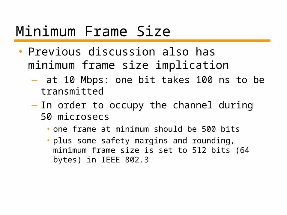
Minimum Frame Size • Previous discussion also has minimum
frame size implication— at 10 Mbps: one bit takes 100 ns to be
transmitted —In order to occupy the channel during 50
microsecs• one frame at minimum should be 500 bits• plus some safety margins and rounding, minimum
frame size is set to 512 bits (64 bytes) in IEEE 802.3
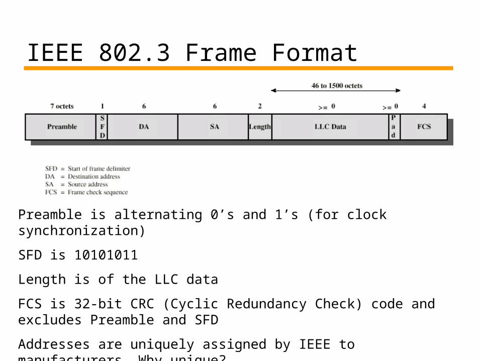
IEEE 802.3 Frame Format
>= >=
Preamble is alternating 0’s and 1’s (for clock synchronization)
SFD is 10101011
Length is of the LLC data
FCS is 32-bit CRC (Cyclic Redundancy Check) code and excludes Preamble and SFD
Addresses are uniquely assigned by IEEE to manufacturers. Why unique?
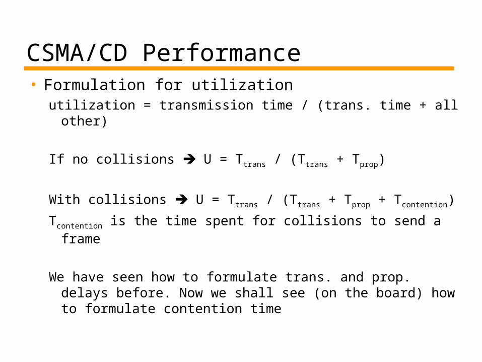
CSMA/CD Performance• Formulation for utilization
utilization = transmission time / (trans. time + all other)
If no collisions U = Ttrans / (Ttrans + Tprop)
With collisions U = Ttrans / (Ttrans + Tprop + Tcontention)
Tcontention is the time spent for collisions to send a frame
We have seen how to formulate trans. and prop. delays before. Now we shall see (on the board) how to formulate contention time
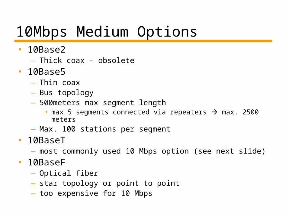
10Mbps Medium Options • 10Base2
—Thick coax - obsolete
• 10Base5—Thin coax —Bus topology—500meters max segment length
• max 5 segments connected via repeaters max. 2500 meters
—Max. 100 stations per segment
• 10BaseT—most commonly used 10 Mbps option (see next slide)
• 10BaseF—Optical fiber —star topology or point to point— too expensive for 10 Mbps
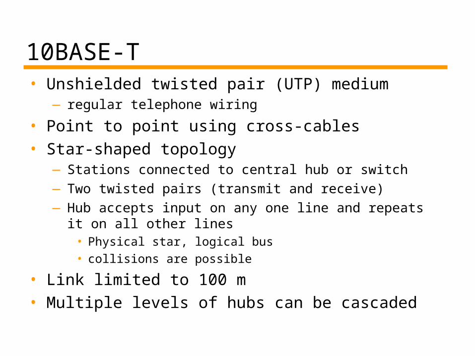
10BASE-T• Unshielded twisted pair (UTP) medium
—regular telephone wiring
• Point to point using cross-cables• Star-shaped topology
—Stations connected to central hub or switch—Two twisted pairs (transmit and receive)—Hub accepts input on any one line and repeats it on all
other lines• Physical star, logical bus• collisions are possible
• Link limited to 100 m • Multiple levels of hubs can be cascaded
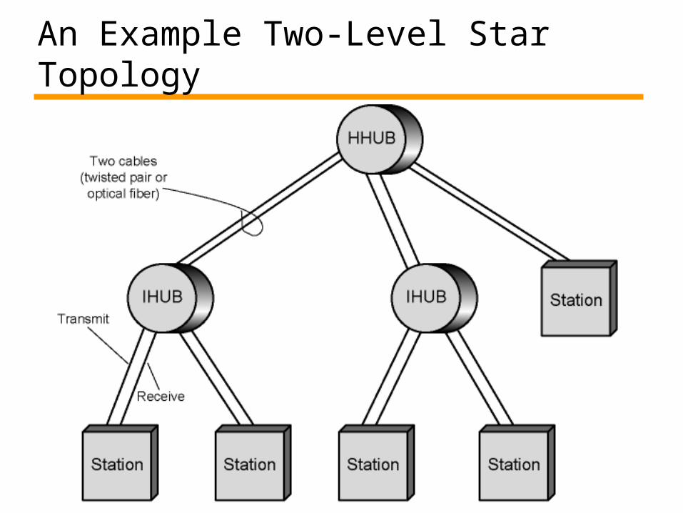
An Example Two-Level Star Topology
Interconnection Elements in LANs• Hubs
• Bridges• Switches• Routers
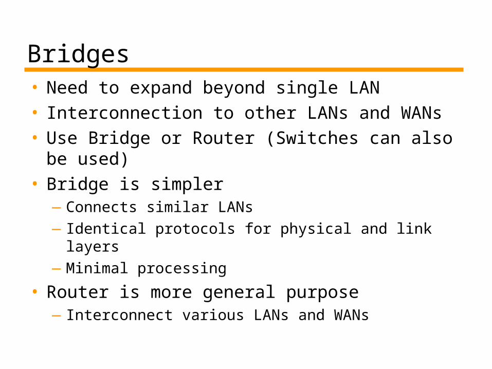
Bridges• Need to expand beyond single LAN• Interconnection to other LANs and WANs• Use Bridge or Router (Switches can also
be used)• Bridge is simpler
—Connects similar LANs—Identical protocols for physical and link layers—Minimal processing
• Router is more general purpose—Interconnect various LANs and WANs
Functions of a Bridge• Read all frames transmitted on one LAN
and accept those addressed to any station on the other LAN
• Retransmit each frame on second LAN• Do the same the other way round
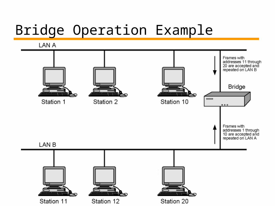
Bridge Operation Example
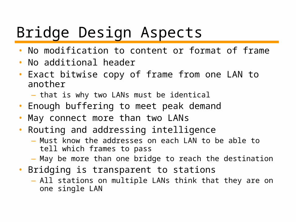
Bridge Design Aspects• No modification to content or format of frame• No additional header• Exact bitwise copy of frame from one LAN to another
— that is why two LANs must be identical
• Enough buffering to meet peak demand• May connect more than two LANs• Routing and addressing intelligence
—Must know the addresses on each LAN to be able to tell which frames to pass
—May be more than one bridge to reach the destination
• Bridging is transparent to stations—All stations on multiple LANs think that they are on one
single LAN
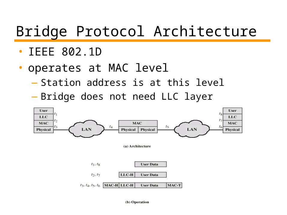
Bridge Protocol Architecture• IEEE 802.1D• operates at MAC level
—Station address is at this level—Bridge does not need LLC layer
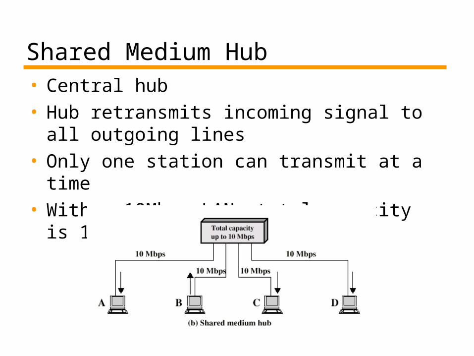
Shared Medium Hub• Central hub• Hub retransmits incoming signal to all
outgoing lines• Only one station can transmit at a time• With a 10Mbps LAN, total capacity is
10Mbps
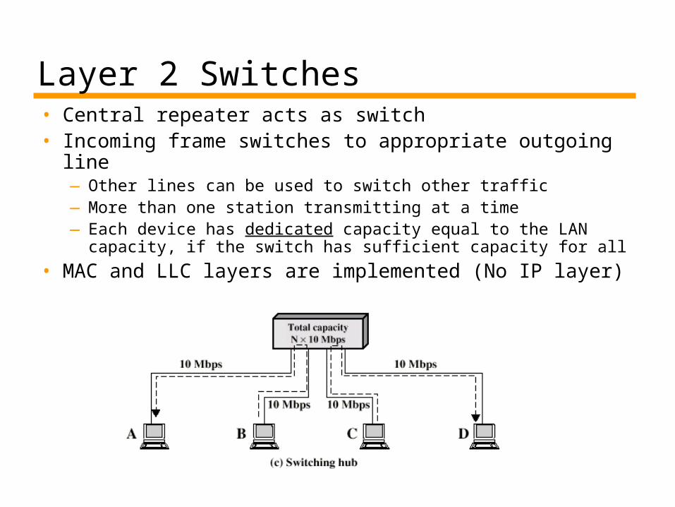
Layer 2 Switches• Central repeater acts as switch• Incoming frame switches to appropriate outgoing
line—Other lines can be used to switch other traffic—More than one station transmitting at a time —Each device has dedicated capacity equal to the LAN
capacity, if the switch has sufficient capacity for all
• MAC and LLC layers are implemented (No IP layer)
Types of Layer 2 Switch• Store and forward switch
—Accept input, buffer it briefly, then output
• Cut through switch—Take advantage of the destination address
being at the start of the frame—Begin repeating incoming frame onto output
line as soon as address recognized—May propagate some bad frames
• WHY?
Layer 2 Switch vs. Bridge• Bridge functionality also exists in layer 2 switches• Some differences
—Bridge only analyzes and forwards one frame at a time—Switch has multiple parallel data paths
• Can handle multiple frames at a time
—Bridge uses store-and-forward operation—Switch also has cut-through operation
• Bridges are not common nowadays—New installations typically include layer 2 switches with
bridge functionality rather than bridges
Problems with Layer 2 Switches (1)• As number of devices in LANs grows, layer 2
switches show some limitations—Broadcast overload
• In LANs some protocols (e.g. ARP) work in broadcast manner
—Lack of multiple routes
• Set of devices and LANs connected by layer 2 switches share common MAC broadcast address—If any device issues broadcast frame, that frame is
delivered to all devices attached to network connected by layer 2 switches and/or bridges
—In large network, broadcast frames can create a significant overhead
Problems with Layer 2 Switches (2) and Solution
• Current standards dictate no closed loops—Only one route is allowed between any two
devices• Limits both performance and reliability.
• Solution: break up network into subnetworks connected by routers (that operate at IP layer)—MAC broadcast frames are limited to devices
and switches contained in single subnetwork—IP-based routers employ sophisticated routing
algorithms • Allow use of multiple routes between subnetworks
going through different routers
Problems with Routers; Layer 3 Switches• Routers are designed to be implemented in software
at the gateway and only process packets to/from outer networks—outside traffic is less than the internal traffic— the same router may create a performance bottleneck in the
heart of a LAN• High-speed LANs and high-performance layer 2 switches pump
millions of packets per second
• Solution: layer 3 switches— Implement IP and the layers below (as in the router)— Implement packet-forwarding logic of router in hardware
• faster
• Two categories—Packet by packet —Flow based—Read the book for details
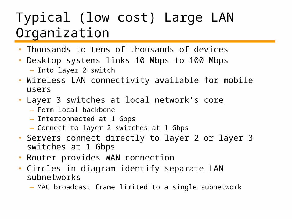
Typical (low cost) Large LAN Organization• Thousands to tens of thousands of devices• Desktop systems links 10 Mbps to 100 Mbps
— Into layer 2 switch
• Wireless LAN connectivity available for mobile users• Layer 3 switches at local network's core
—Form local backbone— Interconnected at 1 Gbps—Connect to layer 2 switches at 1 Gbps
• Servers connect directly to layer 2 or layer 3 switches at 1 Gbps
• Router provides WAN connection• Circles in diagram identify separate LAN subnetworks
—MAC broadcast frame limited to a single subnetwork
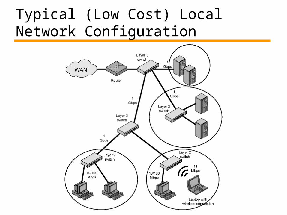
Typical (Low Cost) Local Network Configuration
100Mbps (Fast Ethernet)• 100BaseT4
— to use voice grade cat 3 cables— 3 pairs in each direction with 33.3 Mbps on each using a ternary
signalling scheme (8B6T = 8 bits map to 6 trits)• total 4 pairs (2 of them bidirectional)
— Can be used with cat 5 cables (but waste of resources)• 100Base-X
— Unidirectional data rate of 100 Mbps— Uses two links (one for transmit, one for receive)— Two types: 100Base-TX and 100Base-FX
• 100Base-TX— STP or cat5 UTP (one pair in each direction)— at 125 Mhz with special encoding that has 20% overhead
• 4 bits are encoded using 5-bit time
• 100Base-FX— Optical fiber (one at each direction)— Similar encoding
Fast Ethernet - Details• Same message format as 10 Mbps Ethernet• Fast Ethernet may run in full duplex mode
—So effective data rate per user becomes 200 Mbps—Full duplex mode requires star topology with
switches
• In fact, shared medium no longer exists when switches are used—no collisions, thus CSMA/CD algorithm no longer
needed—but stations still use CSMA/CD and same message
format is used for backward compatibility reasons
Gigabit Ethernet• Strategy same as Fast Ethernet
—New medium and transmission specification—Retains CSMA/CD protocol and frame format—Compatible with 10 and 100 Mbps Ethernet
• Why gigabit Ethernet?— 10/100 Mbps load from end users creates
increased traffic on backbones• so gigabit Ethernet is meaningful for backbones
Gigabit Ethernet – Physical• 1000Base-SX
—Short wavelength, multimode fiber
• 1000Base-LX—Long wavelength, Multi or single mode fiber
• 1000Base-CX—A special STP (<25m)
• one for each direction
• 1000Base-T—4 pairs, cat5 UTP (bidirectional)—100 m
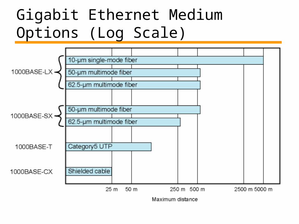
Gigabit Ethernet Medium Options (Log Scale)
10Gbps Ethernet• Why?
—same reasons: increase in traffic, multimedia communications. etc.
• Primarily for high-speed, local backbone interconnection between large-capacity switches
• Allows construction of MANs—Connect geographically dispersed LANs
• Variety of standard optical interfaces (wavelengths and link distances) specified for 10 Gb Ethernet—300 m to 40 kms—full duplex
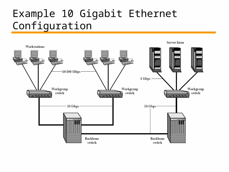
Example 10 Gigabit Ethernet Configuration
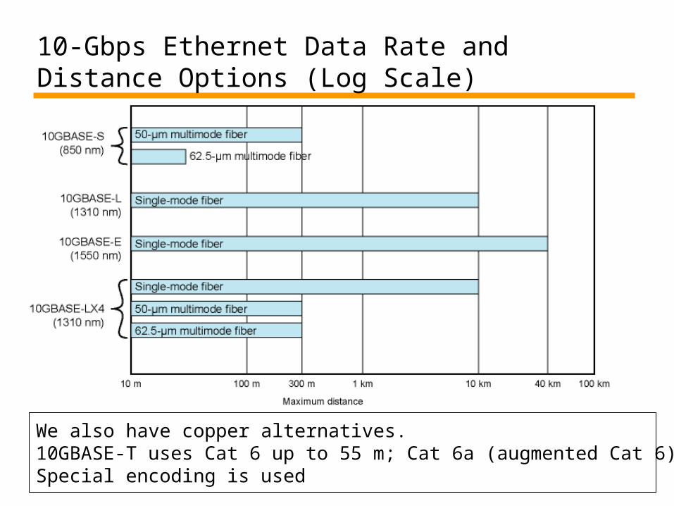
10-Gbps Ethernet Data Rate and Distance Options (Log Scale)
We also have copper alternatives. 10GBASE-T uses Cat 6 up to 55 m; Cat 6a (augmented Cat 6) up to 100 m.Special encoding is used
40 and 100 Gbps Ethernet• Finally arrived • http://www.ieee802.org/3/ba/public/index.
html—IEEE P802.3ba 40Gb/s and 100Gb/s Ethernet
Task Force
• Standardization process is finished in June 2010—IEEE Std 802.3ba-2010
• Some products exist
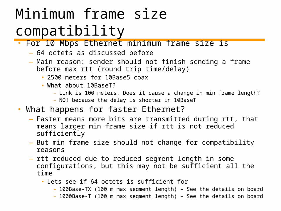
Minimum frame size compatibility• For 10 Mbps Ethernet minimum frame size is
—64 octets as discussed before—Main reason: sender should not finish sending a frame
before max rtt (round trip time/delay)• 2500 meters for 10Base5 coax • What about 10BaseT?
– Link is 100 meters. Does it cause a change in min frame length?– NO! because the delay is shorter in 10BaseT
• What happens for faster Ethernet?—Faster means more bits are transmitted during rtt, that
means larger min frame size if rtt is not reduced sufficiently —But min frame size should not change for compatibility
reasons— rtt reduced due to reduced segment length in some
configurations, but this may not be sufficient all the time• Lets see if 64 octets is sufficient for
– 100Base-TX (100 m max segment length) – See the details on board
– 1000Base-T (100 m max segment length) – See the details on board
Minimum frame size compatibility – Solutions
• From Tanenbaum, section 4.3.8• Reduce segment length
—Not practical! Should reduce to ~50m for gigabit ethernet
• Two practical solutions appeared in standards—Carrier extension
• Sending hardware adds more padding, receiving hardware removes. Thus the standard Ethernet frame remains the same
• Not good for efficiency due to extra padding overhead
—Frame bursting• Sender concatenates several frames• If needed hardware adds more padding
Reading Assignment • Wireless LANs
—Section 15.6, pages 534 - 542
Related Documents