COUNTIS E23/E24 Three-phase active energy meter 63A direct MODBUS Operating instructions EN

Welcome message from author
This document is posted to help you gain knowledge. Please leave a comment to let me know what you think about it! Share it to your friends and learn new things together.
Transcript
COUNTIS E23/E24Three-phase active energy meter
63A direct MODBUSOperating instructions EN
2 COUNTIS E23/E24 - Ref.: 542 103 A
Contents
1. Documentation . . . . . . . . . . . . . . . . . . . . . . . . . . . . . . . . . . . . . . . . . . . . . . . . . . . . . . . . . . . . . . . . . . .3
2. Danger anD warning . . . . . . . . . . . . . . . . . . . . . . . . . . . . . . . . . . . . . . . . . . . . . . . . . . . . . . . . . . . .3
2.1. risk of electrocution, burns or explosion . . . . . . . . . . . . . . . . . . . . . . . . . . . . . . . . . .3
2.2. risk of Damaging Device . . . . . . . . . . . . . . . . . . . . . . . . . . . . . . . . . . . . . . . . . . . . . . . . . . . . . . . .3
3. preliminary operations . . . . . . . . . . . . . . . . . . . . . . . . . . . . . . . . . . . . . . . . . . . . . . . . . . . . . . . .3
4. overview . . . . . . . . . . . . . . . . . . . . . . . . . . . . . . . . . . . . . . . . . . . . . . . . . . . . . . . . . . . . . . . . . . . . . . . . . . .4
4.1. main functions . . . . . . . . . . . . . . . . . . . . . . . . . . . . . . . . . . . . . . . . . . . . . . . . . . . . . . . . . . . . . . . . . .4
4.2. Display views . . . . . . . . . . . . . . . . . . . . . . . . . . . . . . . . . . . . . . . . . . . . . . . . . . . . . . . . . . . . . . . . . . . .4
5. installation . . . . . . . . . . . . . . . . . . . . . . . . . . . . . . . . . . . . . . . . . . . . . . . . . . . . . . . . . . . . . . . . . . . . . . .5
5.1. recommenDations . . . . . . . . . . . . . . . . . . . . . . . . . . . . . . . . . . . . . . . . . . . . . . . . . . . . . . . . . . . . . . .5
5.2. Dimensions (mm) . . . . . . . . . . . . . . . . . . . . . . . . . . . . . . . . . . . . . . . . . . . . . . . . . . . . . . . . . . . . . . . . .5
5.3. terminals . . . . . . . . . . . . . . . . . . . . . . . . . . . . . . . . . . . . . . . . . . . . . . . . . . . . . . . . . . . . . . . . . . . . . . . .5
5.4. connections . . . . . . . . . . . . . . . . . . . . . . . . . . . . . . . . . . . . . . . . . . . . . . . . . . . . . . . . . . . . . . . . . . . . .6
5.4.1. 4-wiRe connection - 4-wiRe loAd monitoRing . . . . . . . . . . . . . . . . . . . . . . . . . . . . .6
5.4.2. 4-wiRe connection - 3-wiRe loAd monitoRing . . . . . . . . . . . . . . . . . . . . . . . . . . . . .6
5.5. sealable covers . . . . . . . . . . . . . . . . . . . . . . . . . . . . . . . . . . . . . . . . . . . . . . . . . . . . . . . . . . . . . . . .6
6. moDbus communication . . . . . . . . . . . . . . . . . . . . . . . . . . . . . . . . . . . . . . . . . . . . . . . . . . . . . . . .7
6.1. general information . . . . . . . . . . . . . . . . . . . . . . . . . . . . . . . . . . . . . . . . . . . . . . . . . . . . . . . . . . .7
6.2. recommenDations . . . . . . . . . . . . . . . . . . . . . . . . . . . . . . . . . . . . . . . . . . . . . . . . . . . . . . . . . . . . . . .7
6.3. communication structure . . . . . . . . . . . . . . . . . . . . . . . . . . . . . . . . . . . . . . . . . . . . . . . . . . . . .7
6.4. communication table . . . . . . . . . . . . . . . . . . . . . . . . . . . . . . . . . . . . . . . . . . . . . . . . . . . . . . . . . . .7
7. programming . . . . . . . . . . . . . . . . . . . . . . . . . . . . . . . . . . . . . . . . . . . . . . . . . . . . . . . . . . . . . . . . . . . . .8
7.1. navigation principle . . . . . . . . . . . . . . . . . . . . . . . . . . . . . . . . . . . . . . . . . . . . . . . . . . . . . . . . . . . .8
7.2. programming menu overview . . . . . . . . . . . . . . . . . . . . . . . . . . . . . . . . . . . . . . . . . . . . . . . . . .8
7.3. DetaileD view of moDbus programming menu . . . . . . . . . . . . . . . . . . . . . . . . . . . . . . . . .9
8. operation . . . . . . . . . . . . . . . . . . . . . . . . . . . . . . . . . . . . . . . . . . . . . . . . . . . . . . . . . . . . . . . . . . . . . . . . . .10
8.1. DetaileD view of menus . . . . . . . . . . . . . . . . . . . . . . . . . . . . . . . . . . . . . . . . . . . . . . . . . . . . . . . . .11
8.2. DetaileD view of "partial energies" . . . . . . . . . . . . . . . . . . . . . . . . . . . . . . . . . . . . . . . . . . . .12
8.3. DetaileD view of "partial energies" reset . . . . . . . . . . . . . . . . . . . . . . . . . . . . . . . . . . . . .12
9. Diagnostic messages . . . . . . . . . . . . . . . . . . . . . . . . . . . . . . . . . . . . . . . . . . . . . . . . . . . . . . . . . . .13
9.1. missing phases . . . . . . . . . . . . . . . . . . . . . . . . . . . . . . . . . . . . . . . . . . . . . . . . . . . . . . . . . . . . . . . . . .13
9.2. phase inversion . . . . . . . . . . . . . . . . . . . . . . . . . . . . . . . . . . . . . . . . . . . . . . . . . . . . . . . . . . . . . . . . .13
9.3. malfunction . . . . . . . . . . . . . . . . . . . . . . . . . . . . . . . . . . . . . . . . . . . . . . . . . . . . . . . . . . . . . . . . . . . . .13
10. assistance . . . . . . . . . . . . . . . . . . . . . . . . . . . . . . . . . . . . . . . . . . . . . . . . . . . . . . . . . . . . . . . . . . . . . . . .13
11. electrical anD technical characteristics . . . . . . . . . . . . . . . . . . . . . . . . . . . . .14
12. miD compliance . . . . . . . . . . . . . . . . . . . . . . . . . . . . . . . . . . . . . . . . . . . . . . . . . . . . . . . . . . . . . . . . .15
3COUNTIS E23/E24 - Ref.: 542 102 A
COUNTIS E23/E24 MODBUS
1. DocumentationAll the documentation for COUNTIS E23/E24 equipment is available online at:www.socomec.com/en/countis-e2x
2. Danger and warning
This equipment must only be installed by professionals.The manufacturer shall not be held responsible for failure to comply with the instructions in this manual.
2.1. Risk of electrocution, burns or explosion• Thedevicemustbeinstalledandservicedonlybyqualifiedpersonnel.
• Alwaysuseanappropriatevoltagedetectiondevicetoconfirmtheabsenceofvoltage.
• Replace all devices, doors, and covers before turning on power to this equipment.
• Always supply the device with the correct rated voltage.
Failure to take these precautions could cause serious injuries.
2.2. Risk of damaging deviceCheck the following:
• the mains frequency (50 Hz).
• the maximum voltage at the voltage input terminals is 276 VAC phase/neutral.
• a maximum current of 63 A.
3. Preliminary operations
For personnel and product safety, please carefully read the contents of these operating instructions before installation.
Check the following points as soon as you receive package containing the COUNTIS E23/E24:
• the packaging is in good condition,
• the product has not been damaged during transportation,
• the product reference number conforms to your order,
• the packaging contains the product, two sealable covers, two plastic seals and a Quick Start guide.
4 COUNTIS E23/E24 - Ref.: 542 103 A
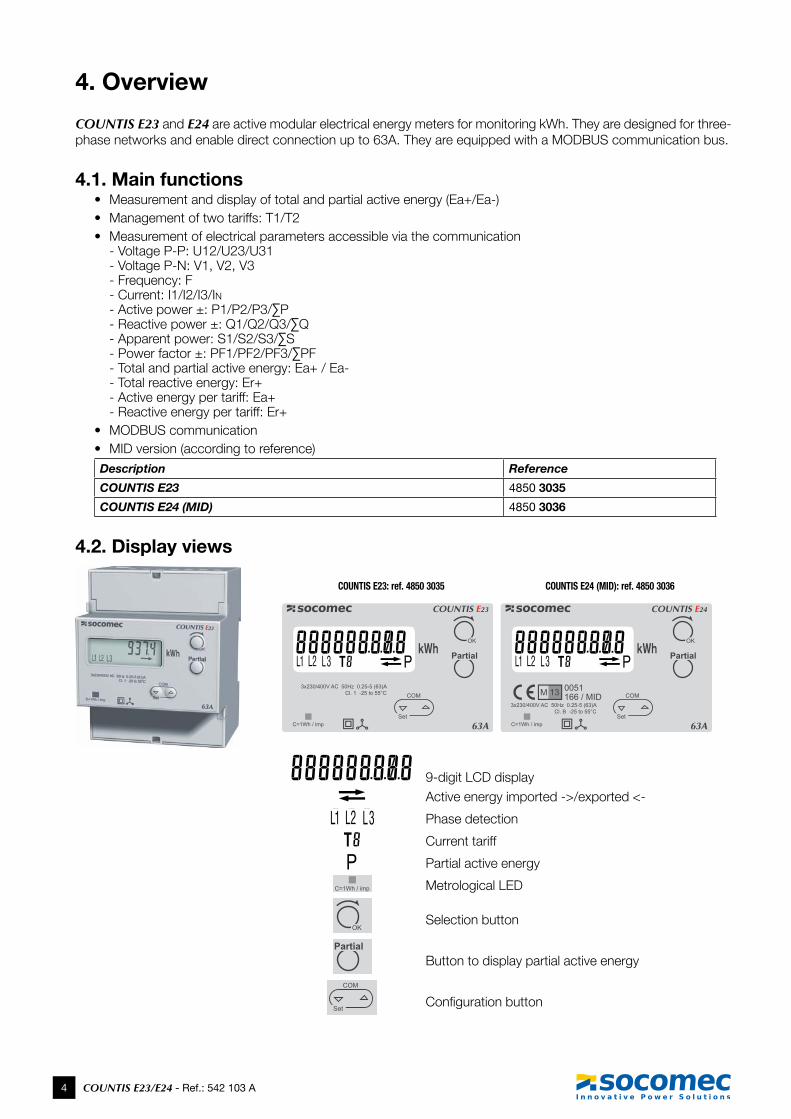
4. Overview
COUNTIS E23 and E24 are active modular electrical energy meters for monitoring kWh. They are designed for three-phase networks and enable direct connection up to 63A. They are equipped with a MODBUS communication bus.
4.1. Main functions• Measurement and display of total and partial active energy (Ea+/Ea-)• Management of two tariffs: T1/T2• Measurement of electrical parameters accessible via the communication
- Voltage P-P: U12/U23/U31 - Voltage P-N: V1, V2, V3 - Frequency: F - Current: I1/I2/I3/In -Activepower±:P1/P2/P3/∑P -Reactivepower±:Q1/Q2/Q3/∑Q -Apparentpower:S1/S2/S3/∑S -Powerfactor±:PF1/PF2/PF3/∑PF - Total and partial active energy: Ea+ / Ea- - Total reactive energy: Er+ - Active energy per tariff: Ea+ - Reactive energy per tariff: Er+
• MODBUS communication• MID version (according to reference) Description Reference
COUNTIS E23 4850 3035
COUNTIS E24 (MID) 4850 3036
4.2. Display views
COUNTIS E23: ref. 4850 3035 COUNTIS E24 (MID): ref. 4850 3036
9-digit LCD display
Active energy imported ->/exported <-
Phase detection
Current tariff
Partial active energy
Metrological LED
Selection button
Button to display partial active energy
Configuration button
5COUNTIS E23/E24 - Ref.: 542 102 A
COUNTIS E23/E24 MODBUS
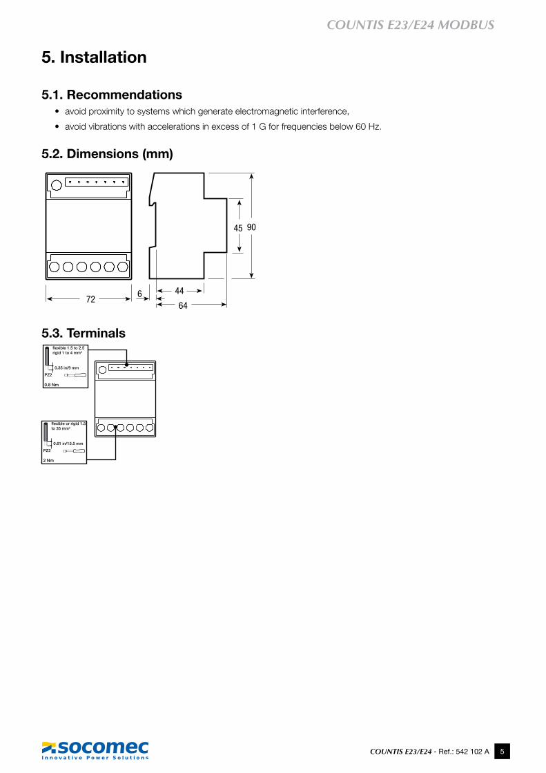
5. Installation
5.1. Recommendations• avoid proximity to systems which generate electromagnetic interference,
• avoid vibrations with accelerations in excess of 1 G for frequencies below 60 Hz.
5.2. Dimensions (mm)
64
45
6
90
4472
5.3. Terminals
64
45
6
90
4472
0.61 in/15.5 mm
pZ2
flexible or rigid 1.5 to 35 mm2
2 nm
0.35 in/9 mm
pZ2
flexible 1.5 to 2.5 rigid 1 to 4 mm2
0.8 nm
6 COUNTIS E23/E24 - Ref.: 542 103 A
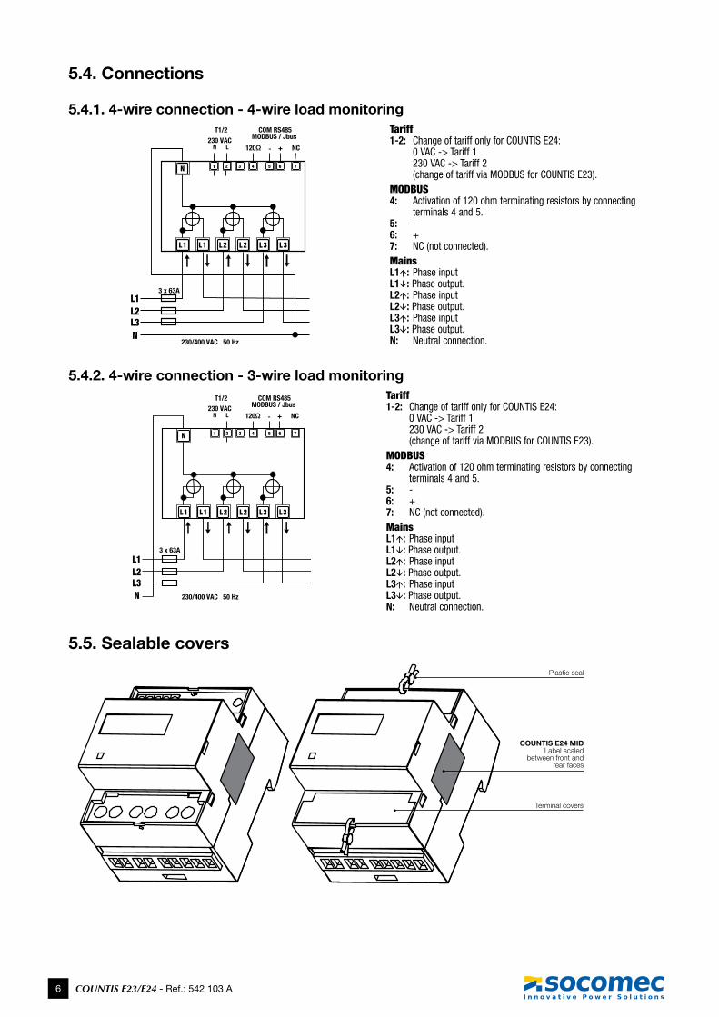
5.4. Connections
5.4.1. 4-wire connection - 4-wire load monitoring
L1L2L3N
L1 L1 L2 L2 L3 L3
N 71 6542 3
L1L2L3N
L1 L1 L2 L2 L3 L3
3 x 63A
230/400 VAC 50 Hz
N 71 6542 3
230 VACCOM RS485
MODBUS / Jbus T1/2
120Ω - + NC
3 x 63A
230/400 VAC 50 Hz
230 VACCOM RS485
MODBUS / Jbus T1/2
120Ω - + NC
Tariff1-2: Change of tariff only for COUNTIS E24:
0 VAC -> Tariff 1 230 VAC -> Tariff 2 (change of tariff via MODBUS for COUNTIS E23).
MODBUS4: Activation of 120 ohm terminating resistors by connecting
terminals 4 and 5.5: -6: +7: NC (not connected).MainsL1: Phase inputL1: Phase output.L2: Phase inputL2: Phase output.L3: Phase inputL3: Phase output.N: Neutral connection.
5.4.2. 4-wire connection - 3-wire load monitoring
L1L2L3N
L1 L1 L2 L2 L3 L3
N 71 6542 3
L1L2L3N
L1 L1 L2 L2 L3 L3
3 x 63A
230/400 VAC 50 Hz
N 71 6542 3
230 VACCOM RS485
MODBUS / Jbus T1/2
120Ω - + NC
3 x 63A
230/400 VAC 50 Hz
230 VACCOM RS485
MODBUS / Jbus T1/2
120Ω - + NC
Tariff1-2: Change of tariff only for COUNTIS E24:
0 VAC -> Tariff 1 230 VAC -> Tariff 2 (change of tariff via MODBUS for COUNTIS E23).
MODBUS4: Activation of 120 ohm terminating resistors by connecting
terminals 4 and 5.5: -6: +7: NC (not connected).MainsL1: Phase inputL1: Phase output.L2: Phase inputL2: Phase output.L3: Phase inputL3: Phase output.N: Neutral connection.
5.5. Sealable covers
Plastic seal
Terminal covers
COUNTIS E24 MIDLabel scaled
between front and rear faces

7COUNTIS E23/E24 - Ref.: 542 102 A
COUNTIS E23/E24 MODBUS
6. MODBUS communication
6.1. General InformationMODBUS® communication is performed via a RS485 serial port (2- or 3-wire) which enables products to be used from a PC or an API.Onastandardconfiguration,aRS485portcanbeusedtoconnect32productstoaPCoraPLCacross1200meters.
R=120Ω
R=120Ω
R=120Ω
R=120Ω R=120Ω R=120Ω
R=120Ω
R=120Ω
R=120Ω
R=120Ω R=120Ω R=120Ω
MODBUS wiring
Wiring with repeater
≈1200mor32UL
≈1200mor32UL ≈1200mor32UL
Repeater
0 -> NC
0 -> NC
6.2. RecommendationsIt is necessary to use a shielded twisted pair (LIYCY type). In an environment where there is interference or large network (in terms of length) we recommend the use of a shielded twisted pair (type LIYCY-CY).A repeater should be used to connect additional products if the distance of 1200 m and/or maximum number of 32 products is exceeded.A120-ohmresistormustbefixedatbothendsofthelink.
6.3. Communication structureThe product communicates via a MODBUS® protocol, which involves a dialogue using a master-slave structure. The mode of communication is the RTU (Remote Terminal Unit) mode using hexadecimal characters of at least 8 bits.
MODBUS® frame structure (master -> slave exchange):
Slave address Function code Address Number of words to read CRC 16
1 byte 1 byte 2 bytes 2 bytes 2 bytes
6.4. Communication tableThe communication tables and associated explanations are available on the COUNTIS E23/E24 documentation page online at the following address:www.socomec.com/en/countis-e2x
8 COUNTIS E23/E24 - Ref.: 542 103 A
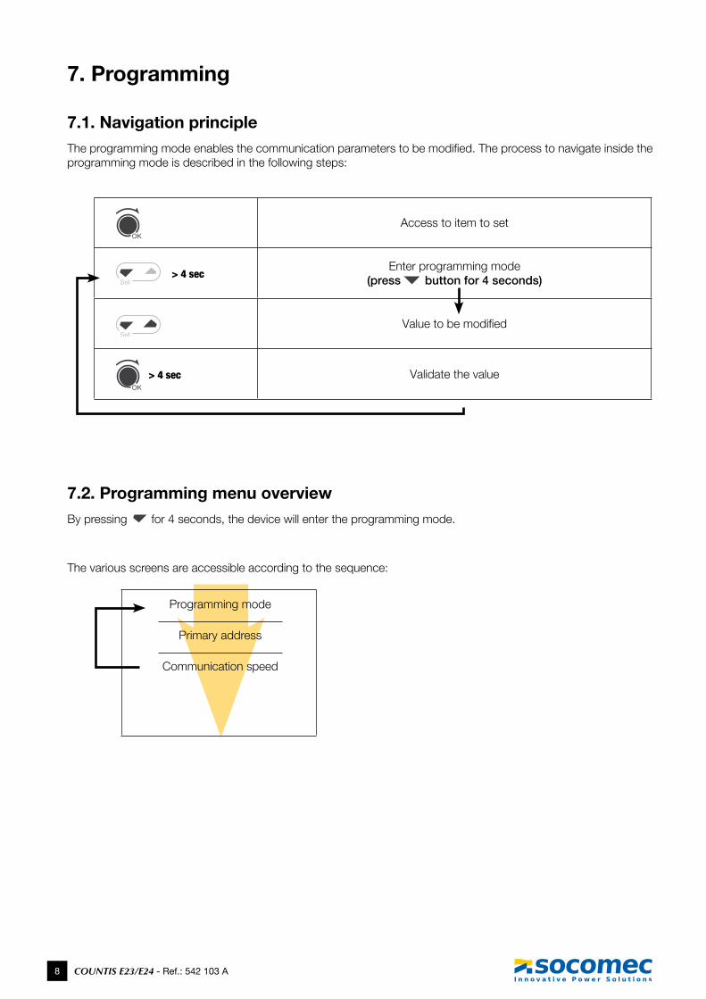
7. Programming
7.1. Navigation principleTheprogrammingmodeenablesthecommunicationparameterstobemodified.Theprocesstonavigateinsidetheprogramming mode is described in the following steps:
Access to item to set
> 4 secEnter programming mode
(press button for 4 seconds)
Value to be modified
> 4 sec Validate the value
7.2. Programming menu overviewBy pressing for 4 seconds, the device will enter the programming mode.
The various screens are accessible according to the sequence:
Programming mode
Primary address
Communication speed
9COUNTIS E23/E24 - Ref.: 542 102 A
COUNTIS E23/E24 MODBUS
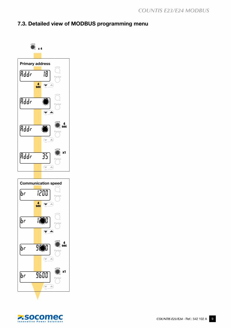
7.3. Detailed view of MODBUS programming menu
x 4
Primary address
4 sec
4 sec
x1
Communication speed
4 sec
4 sec
x1
10 COUNTIS E23/E24 - Ref.: 542 103 A
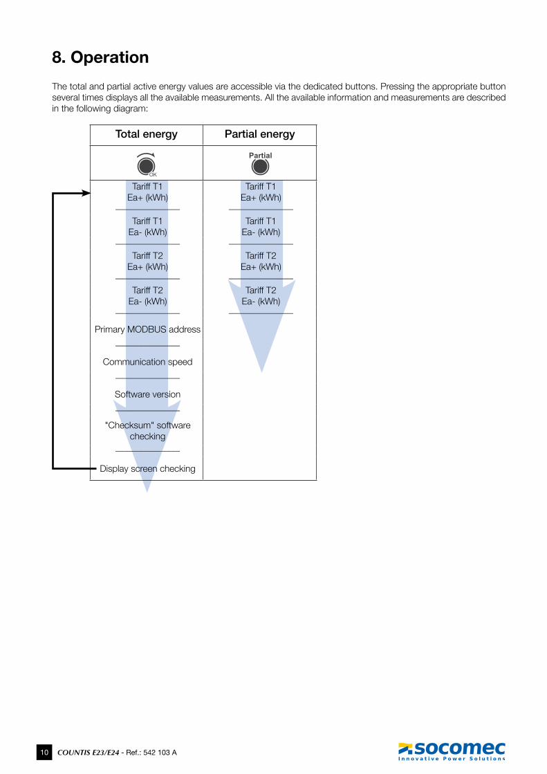
8. Operation
The total and partial active energy values are accessible via the dedicated buttons. Pressing the appropriate button several times displays all the available measurements. All the available information and measurements are described in the following diagram:
Total energy Partial energy
Tariff T1 Ea+ (kWh)
Tariff T1 Ea+ (kWh)
______________ ______________
Tariff T1 Ea- (kWh)
Tariff T1 Ea- (kWh)
______________ ______________
Tariff T2 Ea+ (kWh)
Tariff T2 Ea+ (kWh)
______________ ______________
Tariff T2 Ea- (kWh)
Tariff T2 Ea- (kWh)
______________ ______________
Primary MODBUS address______________
Communication speed______________
Software version______________
"Checksum" software checking
______________
Display screen checking
11COUNTIS E23/E24 - Ref.: 542 102 A
COUNTIS E23/E24 MODBUS
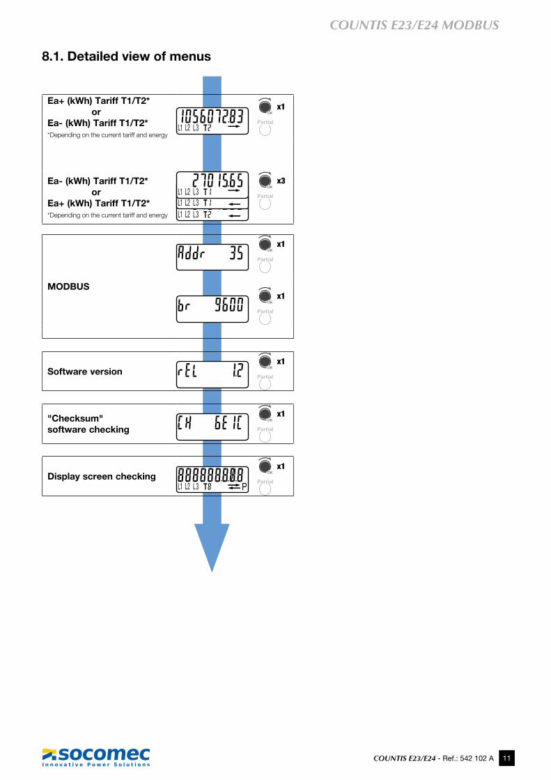
8.1. Detailed view of menus
Ea+ (kWh) Tariff T1/T2*or
Ea- (kWh) Tariff T1/T2** Depending on the current tariff and energy
x1
Ea- (kWh) Tariff T1/T2*or
Ea+ (kWh) Tariff T1/T2** Depending on the current tariff and energy
x3
MODBUS
x1
x1
Software versionx1
"Checksum" software checking
x1
Display screen checkingx1
12 COUNTIS E23/E24 - Ref.: 542 103 A
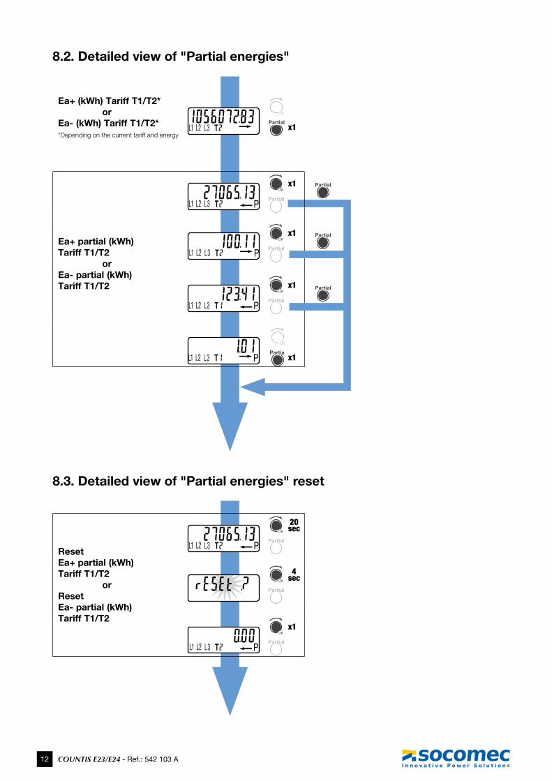
8.2. Detailed view of "Partial energies"
Ea+ (kWh) Tariff T1/T2*or
Ea- (kWh) Tariff T1/T2** Depending on the current tariff and energy
x1
Ea+ partial (kWh) Tariff T1/T2
orEa- partial (kWh) Tariff T1/T2
x1
x1
x1
x1
8.3. Detailed view of "Partial energies" reset
Reset Ea+ partial (kWh) Tariff T1/T2
orReset Ea- partial (kWh) Tariff T1/T2
20 sec
Menu
4 sec
x1
13COUNTIS E23/E24 - Ref.: 542 102 A
COUNTIS E23/E24 MODBUS
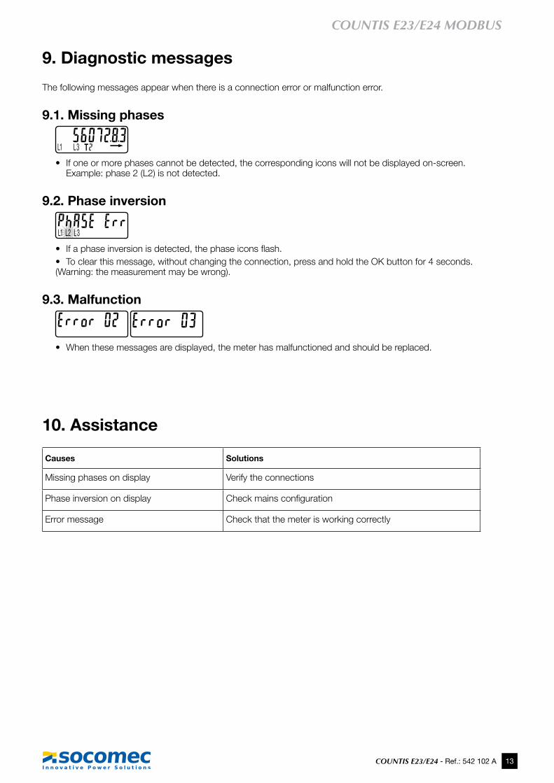
9. Diagnostic messages
The following messages appear when there is a connection error or malfunction error.
9.1. Missing phases
• If one or more phases cannot be detected, the corresponding icons will not be displayed on-screen. Example: phase 2 (L2) is not detected.
9.2. Phase inversion
• If a phaseinversionisdetected,thephaseiconsflash.• To clear this message, without changing the connection, press and hold the OK button for 4 seconds. (Warning: the measurement may be wrong).
9.3. Malfunction
• When these messages are displayed, the meter has malfunctioned and should be replaced.
10. Assistance
Causes Solutions
Missing phases on display Verify the connections
Phase inversion on display Checkmainsconfiguration
Error message Check that the meter is working correctly
14 COUNTIS E23/E24 - Ref.: 542 103 A
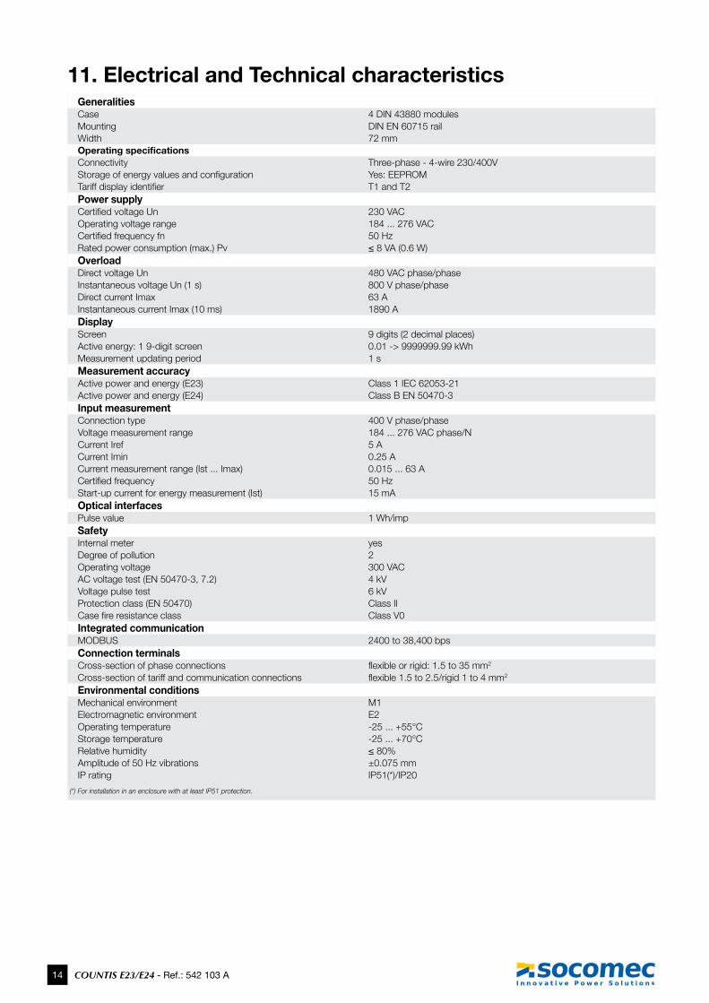
11. Electrical and Technical characteristicsGeneralitiesCase 4 DIN 43880 modulesMounting DIN EN 60715 railWidth 72 mmOperating specificationsConnectivity Three-phase - 4-wire 230/400VStorageofenergyvaluesandconfiguration Yes: EEPROMTariffdisplayidentifier T1 and T2 Power supplyCertifiedvoltageUn 230 VACOperating voltage range 184 ... 276 VACCertifiedfrequencyfn 50 HzRated power consumption (max.) Pv ≤8VA(0.6W)OverloadDirect voltage Un 480 VAC phase/phaseInstantaneous voltage Un (1 s) 800 V phase/phaseDirect current Imax 63 AInstantaneous current Imax (10 ms) 1890 ADisplay Screen 9 digits (2 decimal places) Active energy: 1 9-digit screen 0.01 -> 9999999.99 kWh Measurement updating period 1 sMeasurement accuracyActive power and energy (E23) Class 1 IEC 62053-21Active power and energy (E24) Class B EN 50470-3Input measurementConnection type 400 V phase/phaseVoltage measurement range 184 ... 276 VAC phase/NCurrent Iref 5 ACurrent Imin 0.25 A Current measurement range (Ist ... Imax) 0.015 ... 63 ACertifiedfrequency 50 HzStart-up current for energy measurement (Ist) 15 mAOptical interfacesPulse value 1 Wh/impSafetyInternal meter yesDegree of pollution 2Operating voltage 300 VACAC voltage test (EN 50470-3, 7.2) 4 kVVoltage pulse test 6 kVProtection class (EN 50470) Class IICasefireresistanceclass Class V0Integrated communicationMODBUS 2400 to 38,400 bpsConnection terminalsCross-section of phase connections flexibleorrigid:1.5to35mm2
Cross-section of tariff and communication connections flexible1.5to2.5/rigid1to4mm2
Environmental conditionsMechanical environment M1Electromagnetic environment E2Operating temperature -25 ... +55°CStorage temperature -25 ... +70°CRelative humidity ≤80%Amplitude of 50 Hz vibrations ±0.075 mmIP rating IP51(*)/IP20
(*) For installation in an enclosure with at least IP51 protection.
15COUNTIS E23/E24 - Ref.: 542 102 A
COUNTIS E23/E24 MODBUS
12. MID compliance
The COUNTIS E24 meter complies with the MID directive for connection of three-phase networks (see "5.4. Connections", page 6).
Afterconnectingtheproduct,checkthattheterminalcoversarecorrectlyfittedandsecuredbythe2plasticsealssupplied with the product (see "5.5. Sealable covers", page 6). If the terminal covers must be removed, ensure that the same seal part numbers are used (ref. 4850 304U).
The information given via the communication bus is only sent by way of information and has no legal value.
TheassignedoperatingconditionsguaranteeingMIDcomplianceareavailableinthetechnicalspecificationstables.
The MID declaration of conformity for the COUNTIS E24 is available online at: www.socomec.com/en/countis-e2x
Ref
. 542
103
A -
EN
- 0
9/13
VALID FOR FRANCE
www.socomec.com
hEAD OFFICE
SOCOMEC GROUPS.A. SOCOMEC capital 10 951 300 €R.C.S. Strasbourg B 548 500 149B.P. 60010 - 1, rue de Westhouse F-67235 Benfeld Cedex - FRANCE
InTERnATIOnAL SALES DEpARTMEnT
SOCOMEC1, rue de Westhouse - B.P. 60010 F - 67235 Benfeld Cedex - FRANCETel. +33 (0)3 88 57 41 41 Fax +33 (0)3 88 74 08 [email protected]
Socomec worldwideIn wESTERn EUROpE
BELGIUMB - 1070 Bruxelles Tel. +32 2 340 02 30 [email protected]
FRANCEF - 94132 Fontenay-sous-Bois Cedex Tel. +33 1 45 14 63 30 [email protected]
GERMANYD - 76275 Ettlingen Tel. +49 7243 65292 0 [email protected]
ITALYI - 20098 San Giuliano Milanese (MI) Tel. +39 02 98 49 821 [email protected]
NETHERLANDSNL - 3991 CD Houten Tel. +31 30 760 0900 [email protected]
SPAINE - 08329 Teià (Barcelona)Tel. +34 93 540 75 75 [email protected]
UNITED KINGDOMHitchin Hertfordshire SG4 0TY Tel. +44 1462 440 033 [email protected]
In EASTERn EUROpE, MIDDLE EAST, AFRICA
POLAND01-625 Warszawa Tel. +48 91 442 64 11 [email protected]
ROMANIA023383 Bucharest Tel. +40 21 319 36 88 [email protected]
RUSSIA125167 - Moscow Tel. +7 495 775 19 85 [email protected]
SLOVENIASI - 1000 Ljubljana Tel. +386 1 5807 860 [email protected]
TURKEY34775 Istanbul Tel. +90 216 540 71 20-21-22 [email protected]
UNITED ARAB EMIRATESDubai, U.A.E. Tel. +971 4 29 98 441 [email protected]
Non
con
tract
ual d
ocum
ent.
© 2
013,
Soc
omec
SA
. All
right
s re
serv
ed. -
To
help
pro
tect
the
envi
ronm
ent,
this
doc
umen
t has
bee
n pr
inte
d on
PEF
C p
aper
(Pro
gram
me
for t
he E
ndor
sem
ent o
f For
est C
ertif
icat
ion)
In ASIA
CHINAP.R.C 200052 Shanghai - China Tel. +86 21 52 98 95 55 [email protected]
INDIA122001 Gurgaon, Haryana - India Tel. +91 124 4027210 [email protected]
SINGAPORE Singapore 408723 Tel. +65 6506 7600 [email protected]
In nORTh AMERICA
USA, CANADA & MEXICOCambridge, MA 02142 USA Tel. +1 617 245 0447 [email protected]
YOUR DISTRIBUTOR
Related Documents