Digital Digital Electronics Electronics Electronics Technology Electronics Technology Landon Johnson Counters

Welcome message from author
This document is posted to help you gain knowledge. Please leave a comment to let me know what you think about it! Share it to your friends and learn new things together.
Transcript
Digital ElectronicsDigital Electronics
Electronics TechnologyElectronics Technology
Landon Johnson
Counters
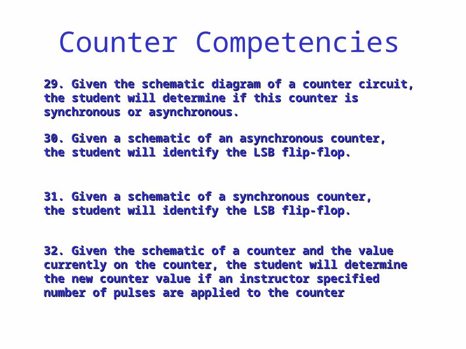
Counter Competencies29. Given the schematic diagram of a counter circuit, the 29. Given the schematic diagram of a counter circuit, the student will determine if this counter is synchronous or student will determine if this counter is synchronous or asynchronous.asynchronous.
30. Given a schematic of an asynchronous counter, 30. Given a schematic of an asynchronous counter, the student will identify the LSB flip-flop.the student will identify the LSB flip-flop.
31. Given a schematic of a synchronous counter, 31. Given a schematic of a synchronous counter, the student will identify the LSB flip-flop.the student will identify the LSB flip-flop.
32. Given the schematic of a counter and the value 32. Given the schematic of a counter and the value currently on the counter, the student will determine currently on the counter, the student will determine the new counter value if an instructor specified the new counter value if an instructor specified number of pulses are applied to the counternumber of pulses are applied to the counter
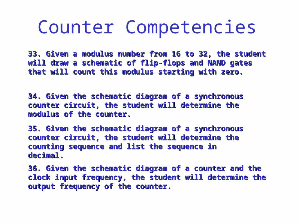
Counter Competencies33. Given a modulus number from 16 to 32, the student 33. Given a modulus number from 16 to 32, the student will draw a schematic of flip-flops and NAND gates that will draw a schematic of flip-flops and NAND gates that will count this modulus starting with zero.will count this modulus starting with zero.
35. Given the schematic diagram of a synchronous 35. Given the schematic diagram of a synchronous counter circuit, the student will determine the counter circuit, the student will determine the counting sequence and list the sequence in counting sequence and list the sequence in decimal.decimal.
34. Given the schematic diagram of a synchronous 34. Given the schematic diagram of a synchronous counter circuit, the student will determine the modulus of counter circuit, the student will determine the modulus of the counter.the counter.
36. Given the schematic diagram of a counter and the 36. Given the schematic diagram of a counter and the clock input frequency, the student will determine the clock input frequency, the student will determine the output frequency of the counter.output frequency of the counter.
COUNTER UNIT
• Asynchronous up and down counters• Asynchronous modulus counters• Seven segment displays/ BCD coding• Synchronous Counters• Pre-settable Counters• Ring Counters
COUNTERS CHARACTERISTICS
1. MODULUS- number of counts in one cycle
2. Up or down count
3. Asynchronous or synchronous operation
4. Free running or self stopping
ASYNCHRONOUS COUNTERS
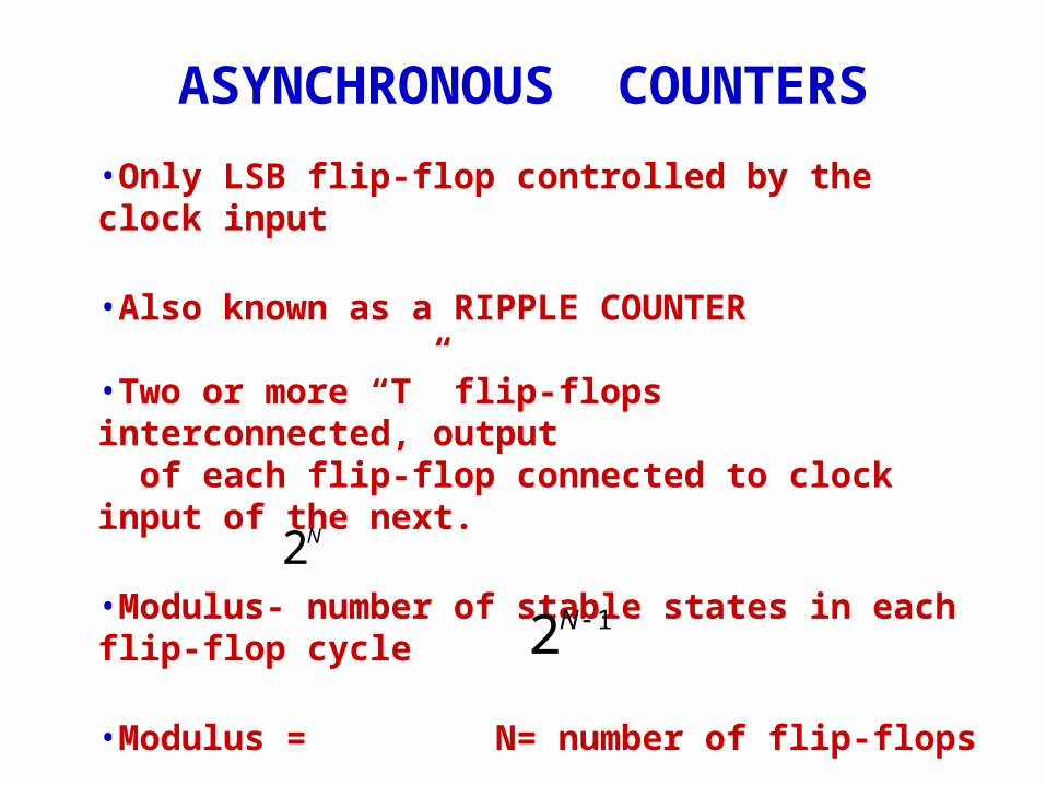
•Only LSB flip-flop controlled by the clock input
•Also known as a RIPPLE COUNTER
•Two or more “T” flip-flops interconnected, output of each flip-flop connected to clock input of the next.
•Modulus- number of stable states in each flip-flop cycle
•Modulus = N= number of flip-flops
•Highest number in count =
N2
12 N
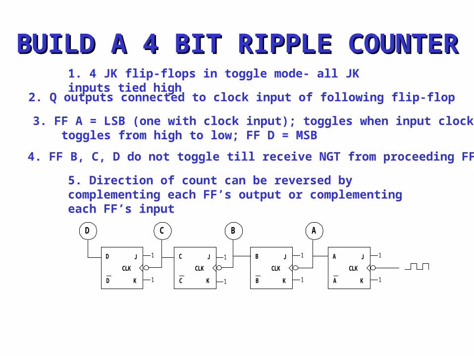
BUILD A 4 BIT RIPPLE BUILD A 4 BIT RIPPLE COUNTERCOUNTER1. 4 JK flip-flops in toggle mode- all JK inputs tied
high2. Q outputs connected to clock input of following flip-flop
3. FF A = LSB (one with clock input); toggles when input clock toggles from high to low; FF D = MSB
4. FF B, C, D do not toggle till receive NGT from proceeding FF
5. Direction of count can be reversed by complementing each FF’s output or complementing each FF’s input
J
K
CLK
B
B
J
K
CLK
C
C
1
1
1
1
1
1
1
1
J
K
CLK
A
A
J
K
CLK
D
D
AC BD
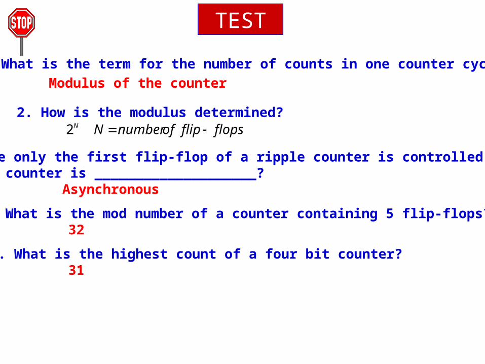
1. What is the term for the number of counts in one counter cycle?
TEST
Modulus of the counter
2. How is the modulus determined? flopsflipofnumberNN 2
3. Since only the first flip-flop of a ripple counter is controlled by a clock, the counter is ____________________?
Asynchronous
4. What is the mod number of a counter containing 5 flip-flops?
5. What is the highest count of a four bit counter?
32
31
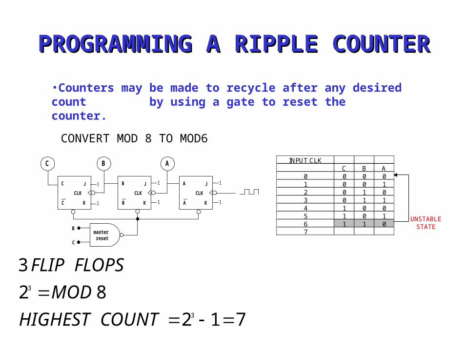
PROGRAMMING A RIPPLE COUNTERPROGRAMMING A RIPPLE COUNTER
•Counters may be made to recycle after any desired count by using a gate to reset the counter.
C
J
K
CLK
B
B
J
K
CLK
C
C
1
1
1
1
1
1
J
K
CLK
A
A
ABINPUT CLK
C B A0 0 0 01 0 0 12 0 1 03 0 1 14 1 0 05 1 0 16 1 1 07
UNSTABLE STATE
CONVERT MOD 8 TO MOD6
712
82
3
3
3
COUNTHIGHEST
MOD
FLOPSFLIP
masterreset
B
C
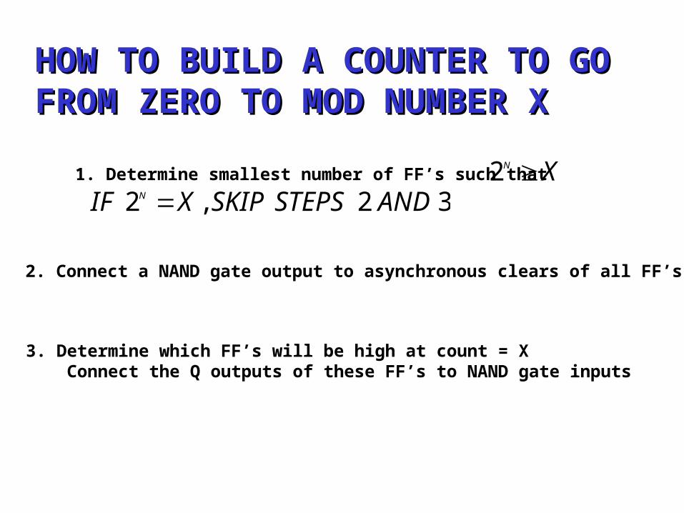
HOW TO BUILD A COUNTER TO GO HOW TO BUILD A COUNTER TO GO FROM ZERO TO MOD NUMBER XFROM ZERO TO MOD NUMBER X
1. Determine smallest number of FF’s such that XN 232,2 ANDSTEPSSKIPXIF N
2. Connect a NAND gate output to asynchronous clears of all FF’s
3. Determine which FF’s will be high at count = X Connect the Q outputs of these FF’s to NAND gate inputs
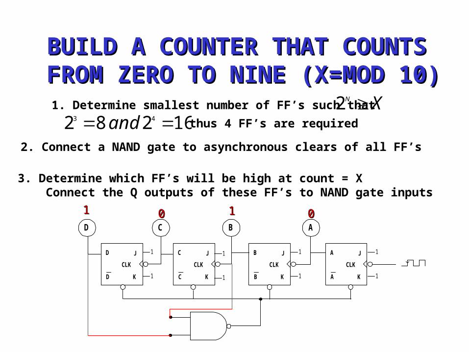
BUILD A COUNTER THAT COUNTSBUILD A COUNTER THAT COUNTS FROM ZERO TO NINE (X=MOD 10)FROM ZERO TO NINE (X=MOD 10)
1. Determine smallest number of FF’s such that XN 216282 43 and thus 4 FF’s are required
2. Connect a NAND gate to asynchronous clears of all FF’s
J
K
CLK
B
B
J
K
CLK
C
C
1
1
1
1
1
1
1
1
J
K
CLK
A
AK
J
CLK
D
D
AC BD
3. Determine which FF’s will be high at count = X Connect the Q outputs of these FF’s to NAND gate inputs
11 1100 00
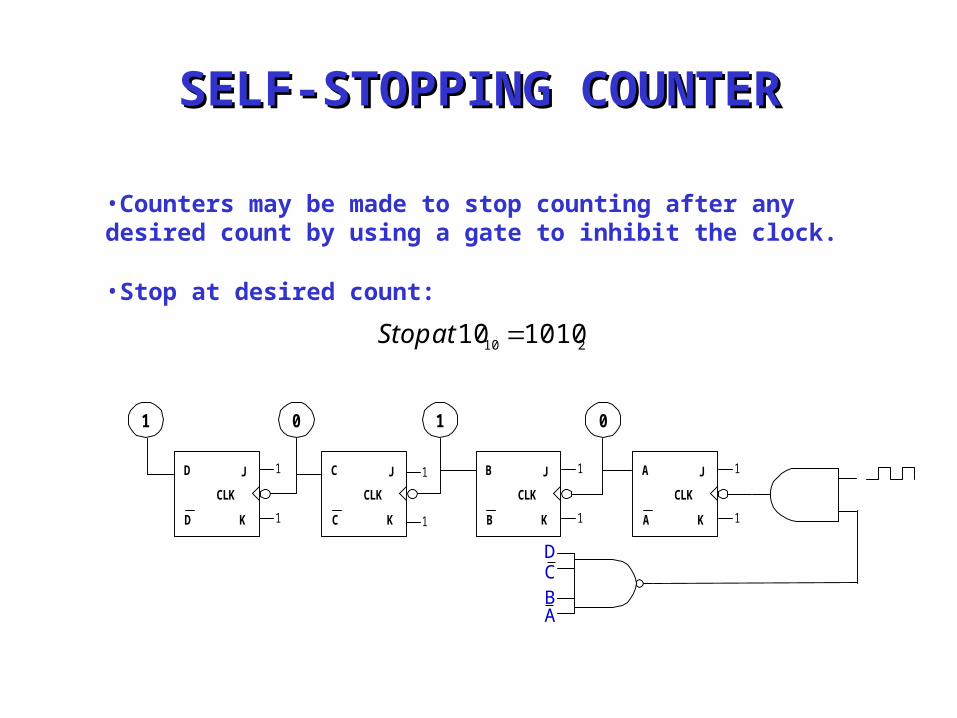
SELF-STOPPING COUNTERSELF-STOPPING COUNTER
•Counters may be made to stop counting after any desired count by using a gate to inhibit the clock.
J
K
CLK
B
B
J
K
CLK
C
C
1
1
1
1
1
1
1
1
J
K
CLK
A
AK
J
CLK
D
D
00 11
•Stop at desired count:
210 101010 atStop
D
BC
A
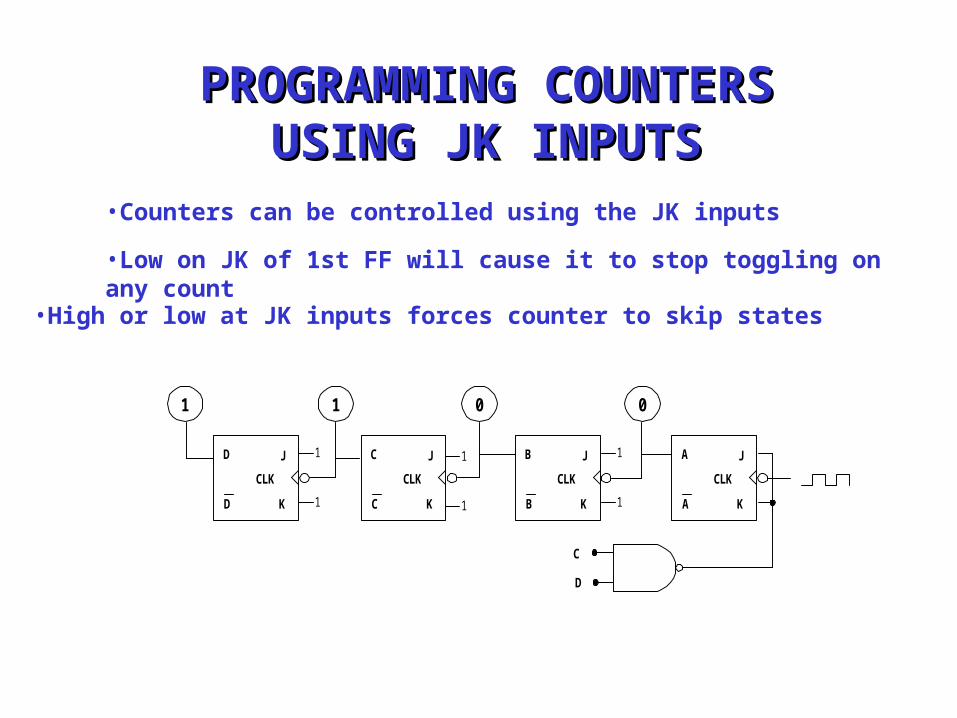
PROGRAMMING COUNTERSPROGRAMMING COUNTERSUSING JK INPUTSUSING JK INPUTS
•Counters can be controlled using the JK inputs
J
K
CLK
B
B
J
K
CLK
C
C
1
1
1
1
1
1
J
K
CLK
A
AK
J
CLK
D
D
C
D
01 01
•Low on JK of 1st FF will cause it to stop toggling on any count
•High or low at JK inputs forces counter to skip states
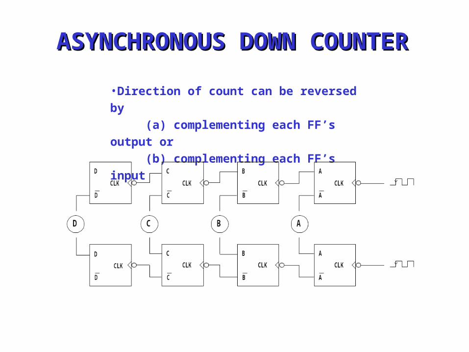
•Direction of count can be reversed by (a) complementing each FF’s output or (b) complementing each FF’s input
ASYNCHRONOUS DOWN COUNTERASYNCHRONOUS DOWN COUNTER
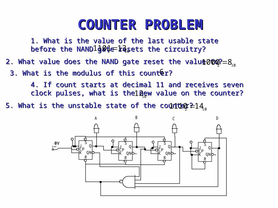
COUNTER COUNTER PROBLEMPROBLEM
A B C D
0V SJCPK
RQN
QS
JCPK
RQN
QS
JCPK
RQN
QS
JCPK
RQN
Q0V S
JCPK
RQN
QS
JCPK
RQN
QS
JCPK
RQN
QS
JCPK
RQN
Q
1. What is the value of the last usable state before the 1. What is the value of the last usable state before the NAND gate resets the circuitry?NAND gate resets the circuitry?
2. What value does the NAND gate reset the value to?2. What value does the NAND gate reset the value to?
3. What is the modulus of this counter?3. What is the modulus of this counter?
4. If count starts at decimal 11 and receives seven clock 4. If count starts at decimal 11 and receives seven clock pulses, what is the new value on the counter?pulses, what is the new value on the counter?
5. What is the unstable state of the counter?5. What is the unstable state of the counter?
102 131101
102 81000 6
1012
102 141110
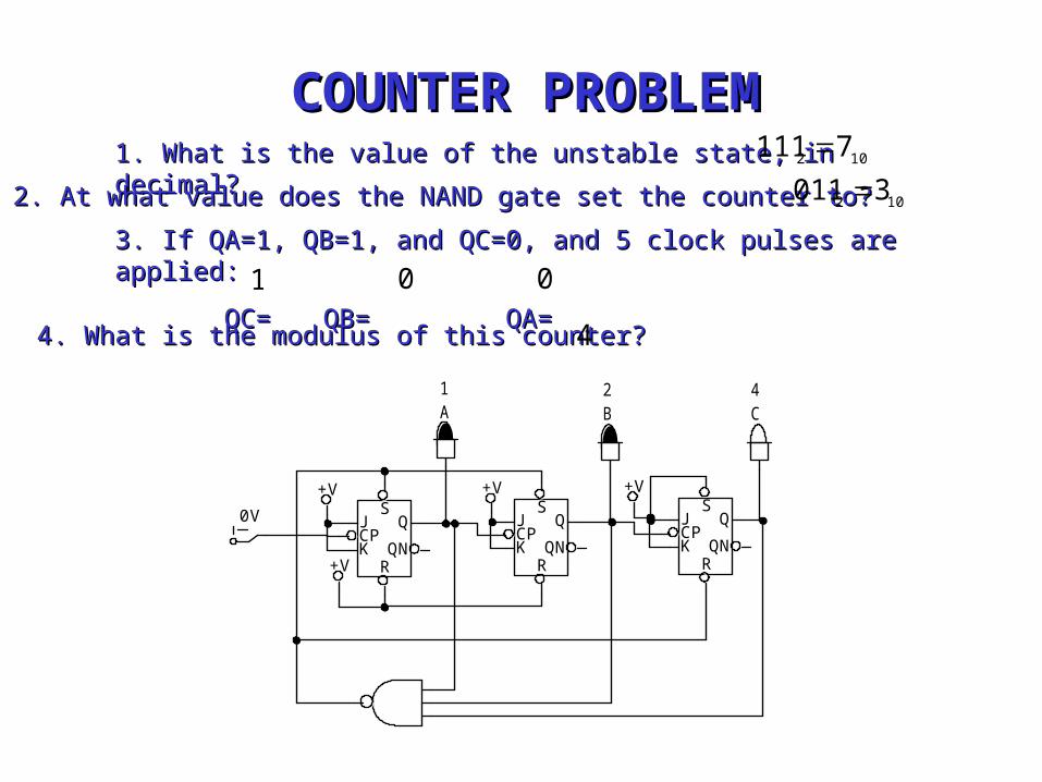
COUNTER COUNTER PROBLEMPROBLEM1. What is the value of the unstable state, in decimal?1. What is the value of the unstable state, in decimal?
2. At what value does the NAND gate set the counter to?2. At what value does the NAND gate set the counter to?
4. What is the modulus of this counter?4. What is the modulus of this counter?
3. If QA=1, QB=1, and QC=0, and 5 clock pulses are applied:3. If QA=1, QB=1, and QC=0, and 5 clock pulses are applied:
QC= QC= QB= QB= QA= QA=
102 7111
102 3011
4
1 0 0
4C
2B
1A
0V
+V+V+V
+V
SJCPK
RQN
QS
JCPK
RQN
QS
JCPK
RQN
Q
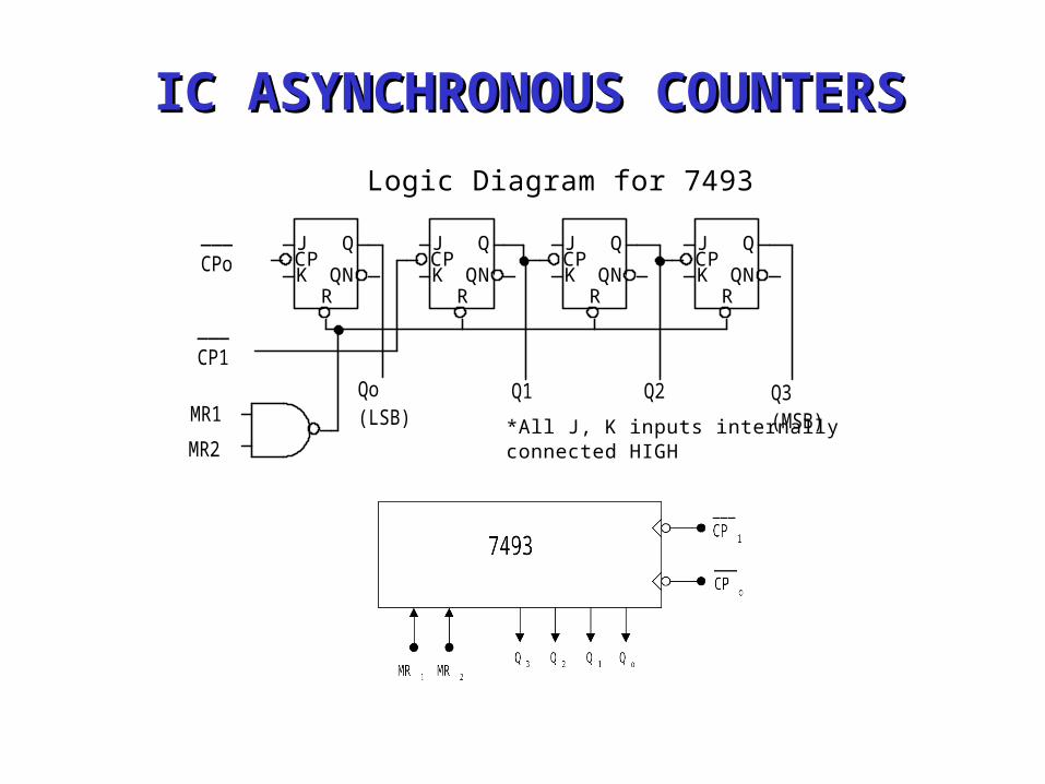
IC ASYNCHRONOUS COUNTERSIC ASYNCHRONOUS COUNTERS
___CPo
___CP1
Qo(LSB)
Q1 Q2 Q3(MSB)MR1
MR2*All J, K inputs internallyconnected HIGH
Logic Diagram for 7493
JCPK
RQN
QJCPK
RQN
QJCPK
RQN
Q JCPK
RQN
Q
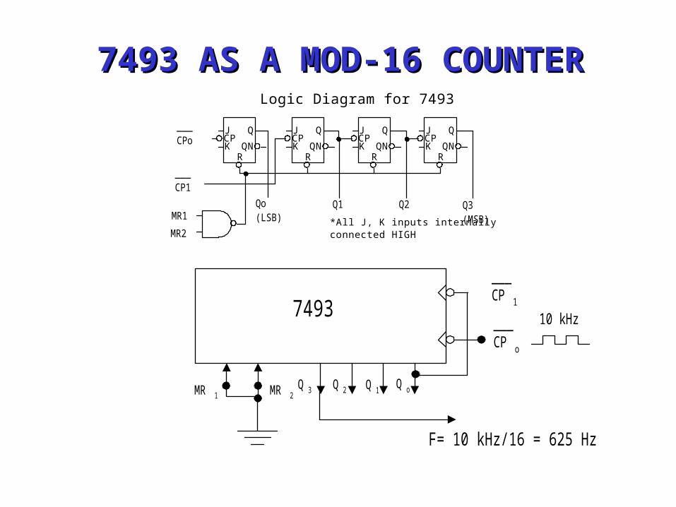
7493 AS A MOD-16 COUNTER7493 AS A MOD-16 COUNTER
___CPo
___CP1
Qo(LSB)
Q1 Q2 Q3(MSB)MR1
MR2*All J, K inputs internallyconnected HIGH
Logic Diagram for 7493
JCPK
RQN
QJCPK
RQN
QJCPK
RQN
Q JCPK
RQN
Q
Q o
7493___CP o
___CP 1
Q 1Q 2Q 3MR 1 MR 2
10 kHz
F= 10 kHz/16 = 625 Hz
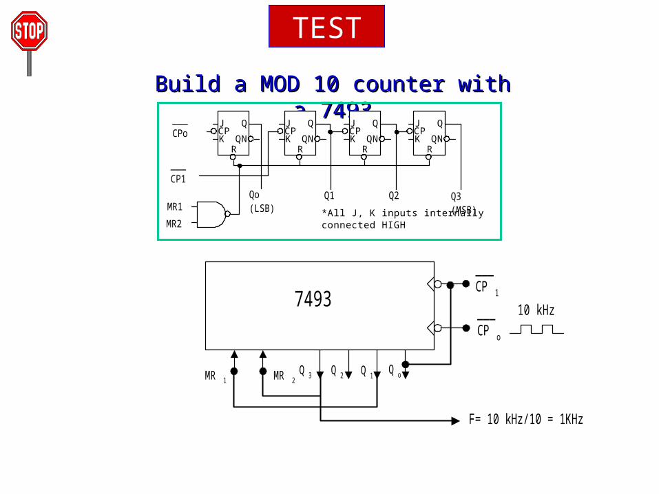
TEST
Build a MOD 10 counter with a Build a MOD 10 counter with a 74937493
10 kHz
MR 2Q o
7493___CP o
___CP 1
Q 1Q 2Q 3MR 1
F= 10 kHz/10 = 1KHz
___CPo
___CP1
Qo(LSB)
Q1 Q2 Q3(MSB)MR1
MR2*All J, K inputs internallyconnected HIGH
Logic Diagram for 7493
JCPK
RQN
QJCPK
RQN
QJCPK
RQN
Q JCPK
RQN
Q
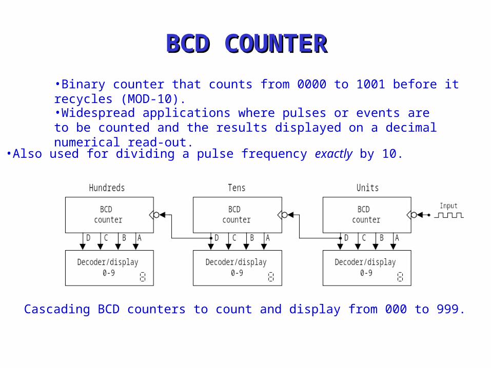
BCD COUNTERBCD COUNTER
•Binary counter that counts from 0000 to 1001 before it recycles (MOD-10).•Widespread applications where pulses or events are to be counted and the results displayed on a decimal numerical read-out.
•Also used for dividing a pulse frequency exactly by 10.
Cascading BCD counters to count and display from 000 to 999.
MR 2Q o
7493___CP o
___CP 1
Q 1Q 2Q 3MR 1MR 2Q o
7493___CP o
___CP 1
Q 1Q 2Q 3not
used
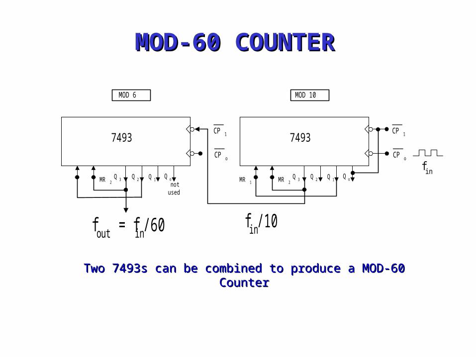
MOD-60 COUNTERMOD-60 COUNTER
MOD 10MOD 6
Two 7493s can be combined to produce a MOD-60 Two 7493s can be combined to produce a MOD-60 CounterCounter
f in/10fout = f in/60
f in
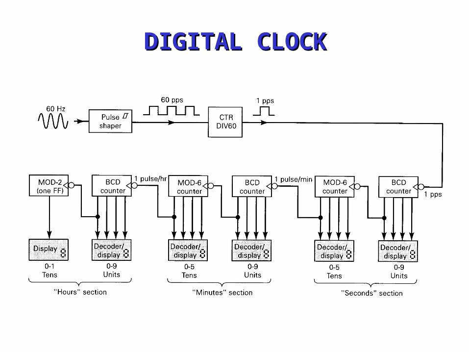
DIGITAL CLOCKDIGITAL CLOCK
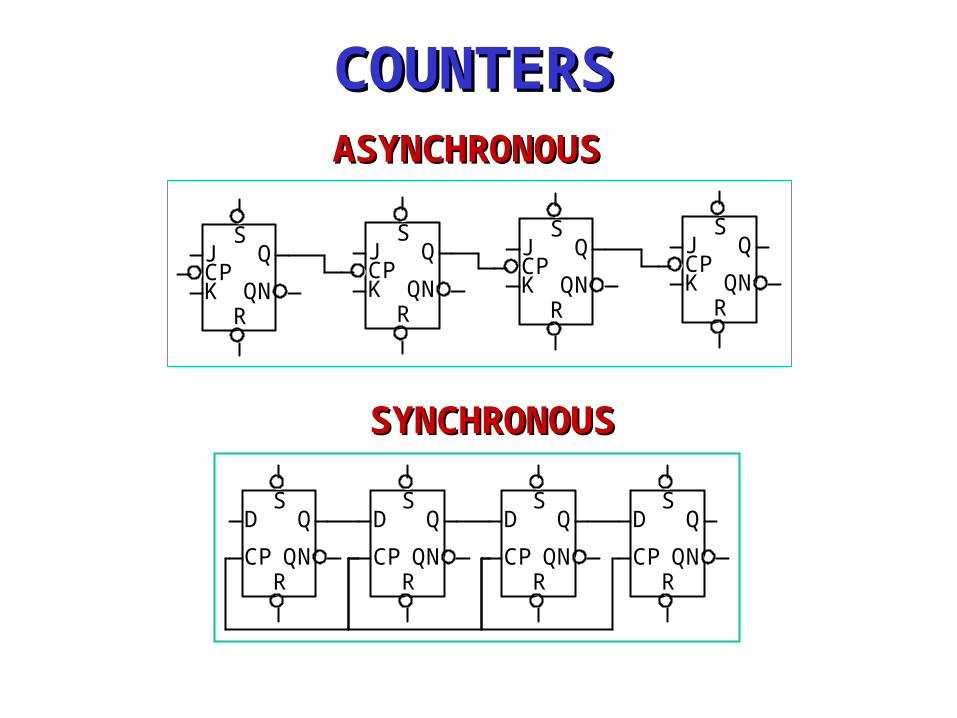
COUNTERSCOUNTERS
SYNCHRONOUSSYNCHRONOUS
SD
CPRQN
QS
D
CPRQN
QS
D
CPRQN
QS
D
CPRQN
Q
ASYNCHRONOUSASYNCHRONOUS
SJCPK
RQN
QS
JCPK
RQN
QS
JCPK
RQN
QS
JCPK
RQN
Q
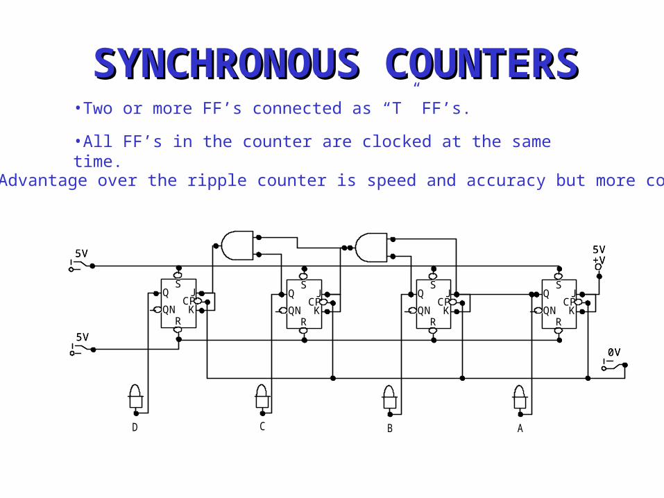
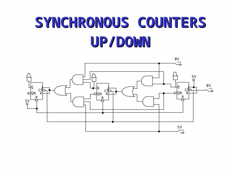
SYNCHRONOUS COUNTERSSYNCHRONOUS COUNTERS•Two or more FF’s connected as “T” FF’s.
•All FF’s in the counter are clocked at the same time.
•Advantage over the ripple counter is speed and accuracy but more complex.
ABCD
0V
5V
5V+V5V
SJ
CPK
RQN
QS
JCPK
RQN
QS
JCPK
RQN
QS
JCPK
RQN
Q
0V
5V
5V+V5V
SJ
CPK
RQN
QS
JCPK
RQN
QS
JCPK
RQN
QS
JCPK
RQN
Q
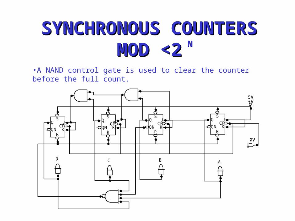
•A NAND control gate is used to clear the counter before the full count.
SYNCHRONOUS COUNTERSSYNCHRONOUS COUNTERSMOD <2MOD <2NN
ABCD
0V
+V5V
SJ
CPK
RQN
QSJ
CPK
RQN
QS
JCPK
RQN
QS
JCPK
RQN
Q
0V
+V5V
SJ
CPK
RQN
QSJ
CPK
RQN
QS
JCPK
RQN
QS
JCPK
RQN
Q
0V
5V
0V
5V
5V
JCPK
RQN
QJCPK
RQN
Q JCPK
RQN
Q
SYNCHRONOUS COUNTERSSYNCHRONOUS COUNTERSUP/DOWNUP/DOWN
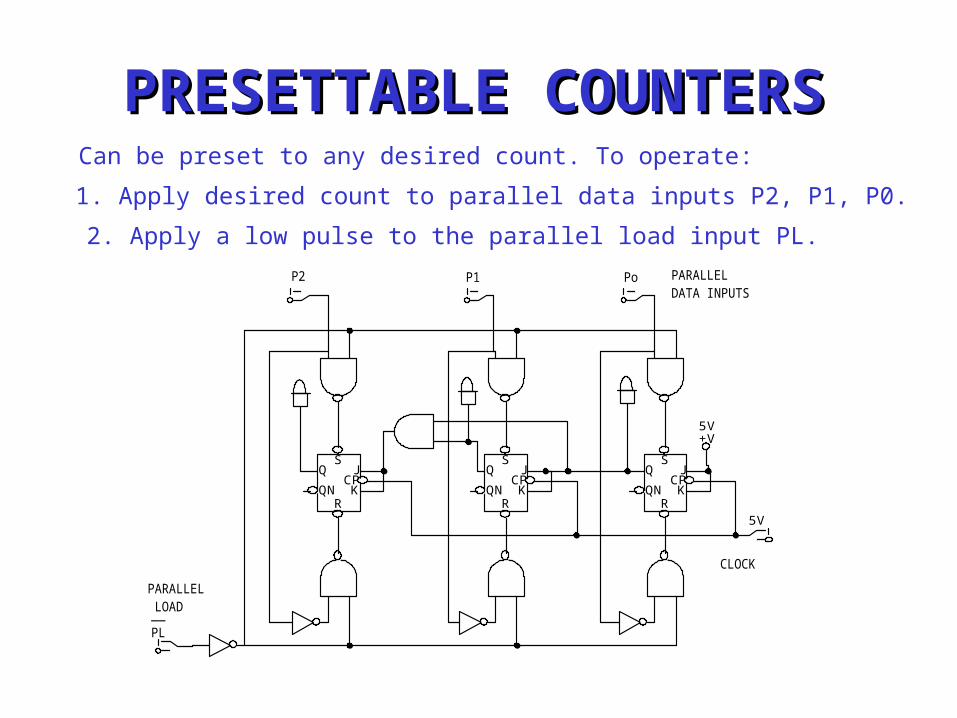
PRESETTABLE COUNTERSPRESETTABLE COUNTERSCan be preset to any desired count. To operate:
1. Apply desired count to parallel data inputs P2, P1, P0.
2. Apply a low pulse to the parallel load input PL.
PARALLEL DATA INPUTS
__PL
P2 P1 Po
CLOCK
PARALLEL LOAD
5V
+V5V
SJ
CPK
RQN
QS
JCPK
RQN
QS
JCPK
RQN
Q
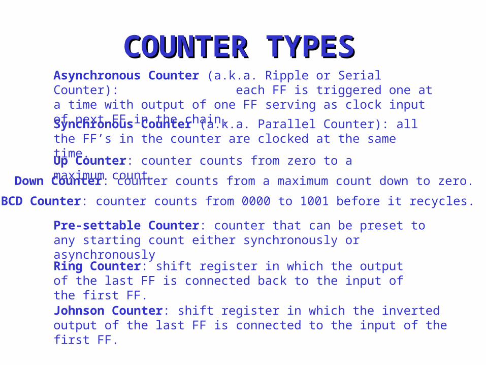
COUNTER TYPESCOUNTER TYPESAsynchronous Counter (a.k.a. Ripple or Serial Counter): each FF is triggered one at a time with output of one FF serving as clock input of next FF in the chain.
Synchronous Counter (a.k.a. Parallel Counter): all the FF’s in the counter are clocked at the same time.
Up Counter: counter counts from zero to a maximum count.Down Counter: counter counts from a maximum count down to zero.
BCD Counter: counter counts from 0000 to 1001 before it recycles.
Pre-settable Counter: counter that can be preset to any starting count either synchronously or asynchronously
Ring Counter: shift register in which the output of the last FF is connected back to the input of the first FF.
Johnson Counter: shift register in which the inverted output of the last FF is connected to the input of the first FF.
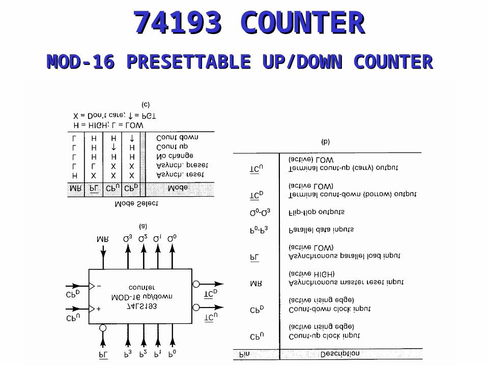
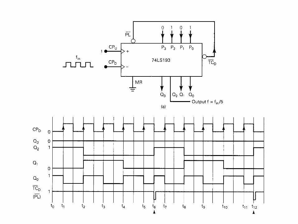
74193 COUNTER74193 COUNTERMOD-16 PRESETTABLE UP/DOWN COUNTERMOD-16 PRESETTABLE UP/DOWN COUNTER
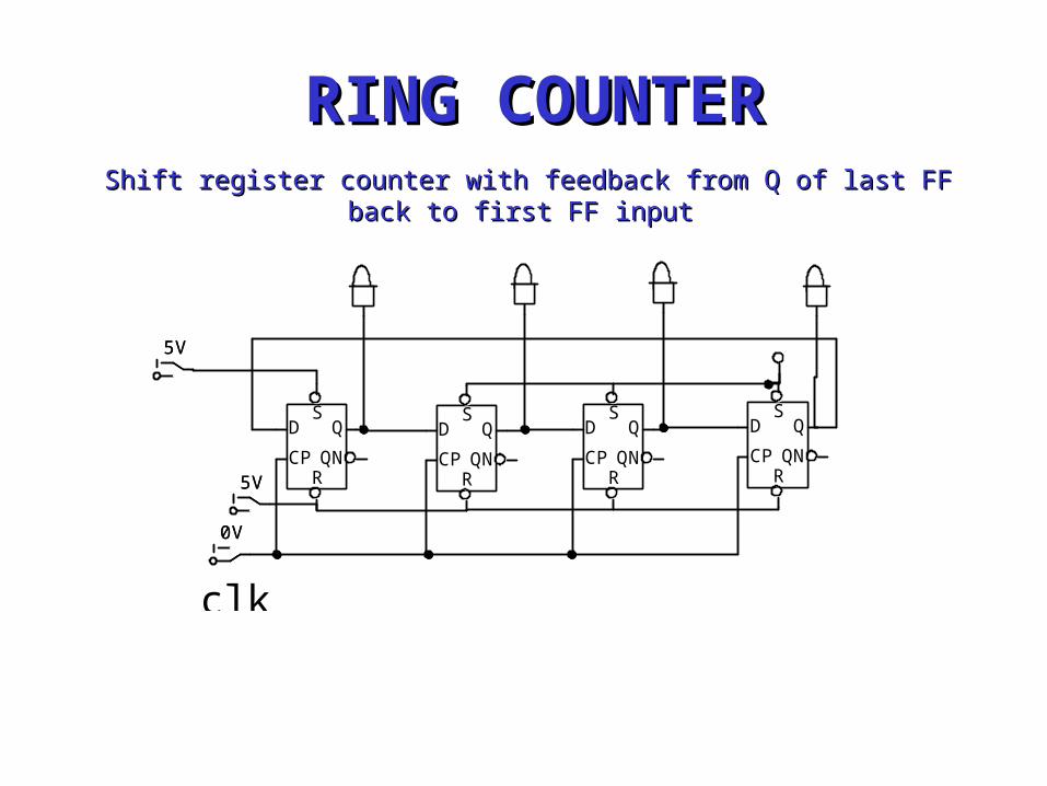
RING COUNTER
clk
5V
0V
5V
SD
CPRQN
QS
D
CPRQN
QS
D
CPRQN
QS
D
CPRQN
Q
5V
0V
5V
SD
CPRQN
QS
D
CPRQN
QS
D
CPRQN
QS
D
CPRQN
Q
RING COUNTERRING COUNTERShift register counter with feedback from Q of last FF back to first Shift register counter with feedback from Q of last FF back to first
FF inputFF input
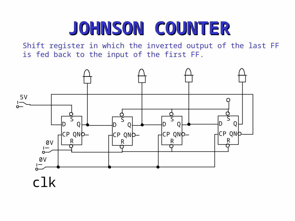
JOHNSON COUNTERJOHNSON COUNTERShift register in which the inverted output of the last FF is fed back to the input of the first FF.
clk
5V
0V
0V
SD
CPRQN
QS
D
CPRQN
QS
D
CPRQN
QS
D
CPRQN
Q
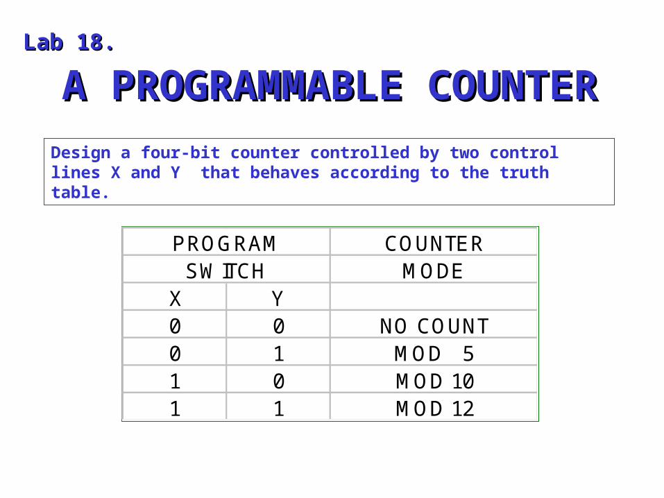
A PROGRAMMABLE COUNTERA PROGRAMMABLE COUNTERLab 18.Lab 18.
Design a four-bit counter controlled by two control lines X and Y that behaves according to the truth table.
PROGRAM COUNTER SWITCH MODE
X Y0 0 NO COUNT0 1 MOD 51 0 MOD 101 1 MOD 12
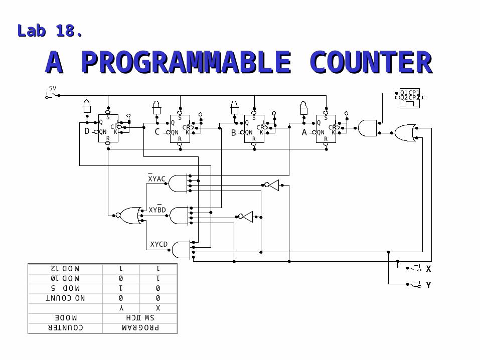
A PROGRAMMABLE COUNTERA PROGRAMMABLE COUNTERLab 18.Lab 18.
ABCD
_XYAC
XYCD
_XYBD
X
Y
5VCP1CP2
Q1Q2
SJ
CPK
RQN
QS
JCPK
RQN
QS
JCPK
RQN
QS
JCPK
RQN
Q
PROGRAMCOUNTER SWITCHMODE
XY00NO COUNT01MOD 510MOD 1011MOD 12
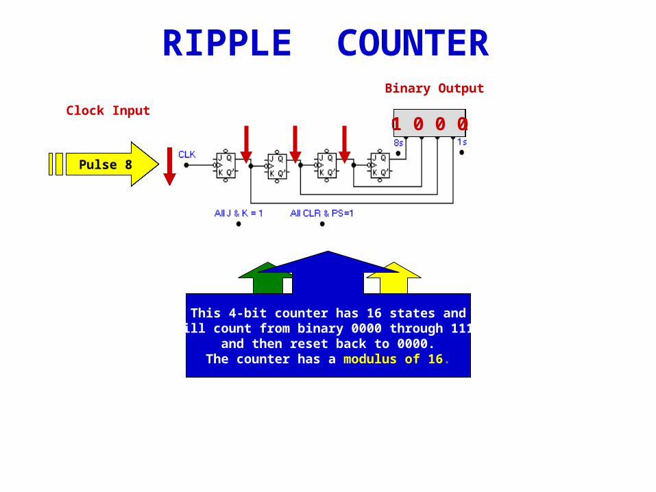
RIPPLE COUNTER
0 0 0 00 0 0 1
Binary Output
0 0 1 00 0 1 10 1 0 00 1 0 10 1 1 00 1 1 11 0 0 0
Pulse 1
Clock Input
All J-K flip-flopsin the
TOGGLE MODE
PS and CLR inputare
INACTIVE
Pulse 2Pulse 3Pulse 4Pulse 5Pulse 6Pulse 7Pulse 8
On the next clock pulse (8) all FFswill toggle because each will receive
a H-to-L pulse- one after another.Watch the count ripple thru the counter.
This 4-bit counter has 16 states andwill count from binary 0000 through 1111
and then reset back to 0000.The counter has a modulus of 16.
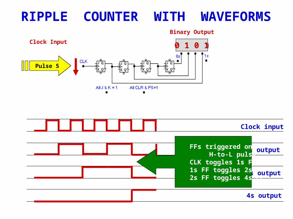
RIPPLE COUNTER WITH WAVEFORMS
0 0 0 00 0 0 1
Binary Output
0 0 1 00 0 1 10 1 0 00 1 0 1
Pulse 1
Clock Input
Pulse 2Pulse 3Pulse 4Pulse 5
Clock input
1s output
2s output
4s output
FFs triggered on H-to-L pulse. CLK toggles 1s FF. 1s FF toggles 2s FF. 2s FF toggles 4s FF.
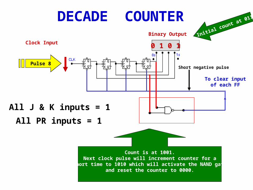
DECADE COUNTERBinary Output
0 1 1 11 0 0 0
Pulse 1
Clock Input
Pulse 2Pulse 3Pulse 4Pulse 5Pulse 6Pulse 7Pulse 8
To change mod-16 counter to decade counter:Reset count to 0000 after 1001 (9) count.
When count hits 1010 reset to 0000.See added 2-input NAND gate that clears all
JK FFs to 0 when count hits 1010.
1 0 0 10 0 0 00 0 0 10 0 1 00 0 1 10 1 0 00 1 0 1
Count is at 1001.Next clock pulse will increment counter for a
short time to 1010 which will activate the NAND gateand reset the counter to 0000.
Initial count at 0111
Short negative pulse
To clear inputof each FF
All J & K inputs = 1
All PR inputs = 1
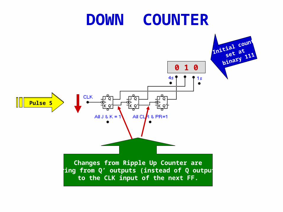
DOWN COUNTER
Changes from Ripple Up Counter arewiring from Q’ outputs (instead of Q outputs)
to the CLK input of the next FF.
Pulse 1Pulse 2
1 1 11 1 0
Initial count
set at
binary 111
1 0 1
Pulse 3Pulse 4
1 0 00 1 1
Pulse 5
0 1 0
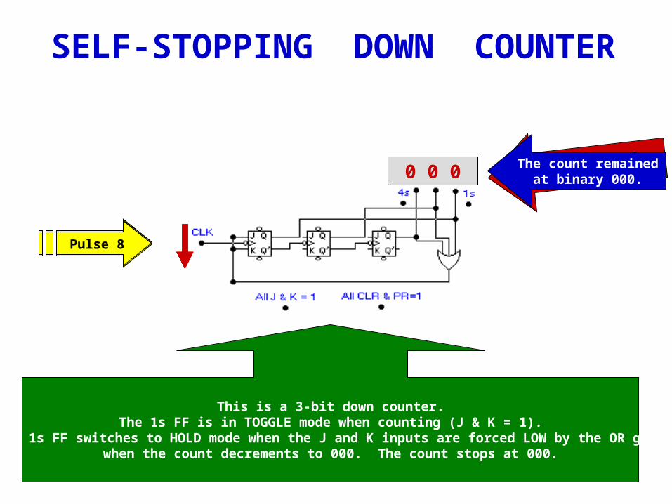
SELF-STOPPING DOWN COUNTER
Pulse 1Pulse 2Pulse 3Pulse 4Pulse 5
1 1 11 1 01 0 11 0 00 1 10 1 0
This is a 3-bit down counter.The 1s FF is in TOGGLE mode when counting (J & K = 1).
The 1s FF switches to HOLD mode when the J and K inputs are forced LOW by the OR gatewhen the count decrements to 000. The count stops at 000.
0 0 1
Pulse 6
0 0 0
Pulse 7Pulse 8
Watch count on
Pulse 8.The count remained
at binary 000.
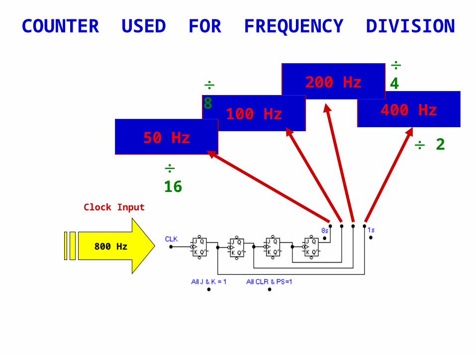
COUNTER USED FOR FREQUENCY DIVISION
Clock Input
800 Hz
400 Hz
200 Hz
100 Hz
50 Hz 2
4
8
16
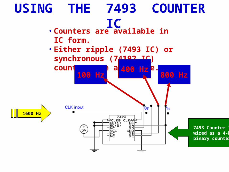
USING THE 7493 COUNTER IC• Counters are available in IC form.• Either ripple (7493 IC) or synchronous
(74192 IC) counters are available.
7493 Counter IC wired as a 4-bit binary counter
1600 Hz
? Hz800 Hz? Hz100 Hz? Hz400 Hz
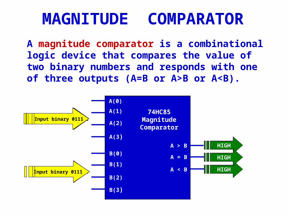
MAGNITUDE COMPARATOR
A magnitude comparator is a combinational logic device that compares the value of two binary numbers and responds with one of three outputs (A=B or A>B or A<B).
Input binary 0001
Input binary 1100 HIGH
HIGH
Input binary 1111
Input binary 0110
Input binary 0111
Input binary 0111
HIGH
74HC85MagnitudeComparator
A = B
A < B
A > B
A(0)
A(1)
A(2)
A(3)
B(0)
B(1)
B(2)
B(3)
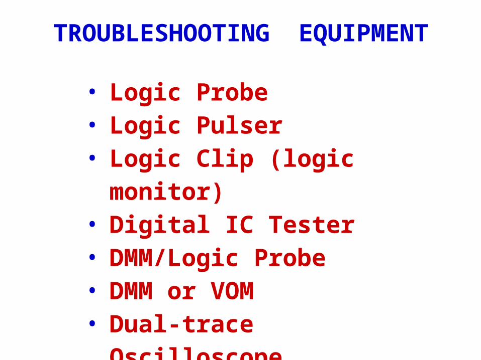
TROUBLESHOOTING EQUIPMENT
• Logic Probe• Logic Pulser• Logic Clip (logic monitor)• Digital IC Tester• DMM/Logic Probe• DMM or VOM• Dual-trace Oscilloscope• Logic Analyzer
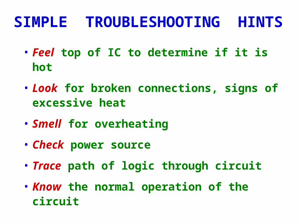
SIMPLE TROUBLESHOOTING HINTS
• Feel top of IC to determine if it is hot
• Look for broken connections, signs of excessive heat
• Smell for overheating
• Check power source
• Trace path of logic through circuit
• Know the normal operation of the circuit
Related Documents