Corrosion-resistant, Bolted Bonnet Gate Valves—Flanged and Butt-welding Ends API STANDARD 603 NINTH EDITION, SEPTEMBER 2018 API MONOGRAM PROGRAM EFFECTIVE DATE: MARCH 2019 falatghareh.ir falatghareh.ir

Welcome message from author
This document is posted to help you gain knowledge. Please leave a comment to let me know what you think about it! Share it to your friends and learn new things together.
Transcript
falatghareh.irfalatghareh.ir
Corrosion-resistant, Bolted Bonnet Gate Valves—Flanged and Butt-welding Ends
API STANDARD 603
NINTH EDITION, SEPTEMBER 2018
API MONOGRAM PROGRAM EFFECTIVE DATE: MARCH 2019
Special Notes
API publications necessarily address problems of a general nature. With respect to particular circumstances, local, state, and federal laws and regulations should be reviewed.
Neither API nor any of API’s employees, subcontractors, consultants, committees, or other assignees make any warranty or representation, either express or implied, with respect to the accuracy, completeness, or usefulness of the information contained herein, or assume any liability or responsibility for any use, or the results of such use, of any information or process disclosed in this publication. Neither API nor any of API’s employees, subcontractors, consultants, or other assignees represent that use of this publication would not infringe upon privately owned rights.
API publications may be used by anyone desiring to do so. Every effort has been made by the Institute to ensure the accuracy and reliability of the data contained in them; however, the Institute makes no representation, warranty, or guarantee in connection with this publication and hereby expressly disclaims any liability or responsibility for loss or damage resulting from its use or for the violation of any authorities having jurisdiction with which this publication may conflict.
API publications are published to facilitate the broad availability of proven, sound engineering and operating practices. These publications are not intended to obviate the need for applying sound engineering judgment regarding when and where these publications should be utilized. The formulation and publication of API publications is not intended in any way to inhibit anyone from using any other practices.
Any manufacturer marking equipment or materials in conformance with the marking requirements of an API standard is solely responsible for complying with all the applicable requirements of that standard. API does not represent, warrant, or guarantee that such products do in fact conform to the applicable API standard.
Users of this Standard should not rely exclusively on the information contained in this document. Sound business, scientific, engineering, and safety judgment should be used in employing the information contained herein.
API is not undertaking to meet the duties of employers, manufacturers, or suppliers to warn and properly train and equip their employees, and others exposed, concerning health and safety risks and precautions, nor undertaking their obligations to comply with authorities having jurisdiction.
All rights reserved. No part of this work may be reproduced, translated, stored in a retrieval system, or transmitted by any means, electronic, mechanical, photocopying, recording, or otherwise, without prior written permission from the publisher. Contact the
Publisher, API Publishing Services, 1220 L Street, NW, Washington, DC 20005.
Copyright © 2018 American Petroleum Institute
falatghareh.irfalatghareh.ir
Foreword
Nothing contained in any API publication is to be construed as granting any right, by implication or otherwise, for the manufacture, sale, or use of any method, apparatus, or product covered by letters patent. Neither should anything contained in the publication be construed as insuring anyone against liability for infringement of letters patent.
The verbal forms used to express the provisions in this document are as follows.
Shall: As used in a standard, “shall” denotes a minimum requirement in order to conform to the standard.
Should: As used in a standard, “should” denotes a recommendation or that which is advised but not required in order to conform to the standard.
May: As used in a standard, “may” denotes a course of action permissible within the limits of a standard.
Can: As used in a standard, “can” denotes a statement of possibility or capability.
This document was produced under API standardization procedures that ensure appropriate notification and participation in the developmental process and is designated as an API standard. Questions concerning the interpretation of the content of this publication or comments and questions concerning the procedures under which this publication was developed should be directed in writing to the Director of Standards, American Petroleum Institute, 1220 L Street, NW, Washington, DC 20005. Requests for permission to reproduce or translate all or any part of the material published herein should also be addressed to the director.
Generally, API standards are reviewed and revised, reaffirmed, or withdrawn at least every five years. A one-time extension of up to two years may be added to this review cycle. Status of the publication can be ascertained from the API Standards Department, telephone (202) 682-8000. A catalog of API publications and materials is published annually by API, 1220 L Street, NW, Washington, DC 20005.
For API Monogram Program licensees and APIQR program registrants, this Standard shall become effective on the program date printed on the cover but may be used voluntarily from the date of publication.
Suggested revisions are invited and should be submitted to the Standards Department, API, 1220 L Street, NW, Washington, DC 20005, [email protected].
iii
falatghareh.irfalatghareh.ir

falatghareh.irfalatghareh.ir
Contents
Page
falatghareh.irfalatghareh.ir
1 Scope . . . . . . . . . . . . . . . . . . . . . . . . . . . . . . . . . . . . . . . . . . . . . . . . . . . . . . . . . . . . . . . . . . . . . . . . . . . . . . . . . . 1
2 Normative References . . . . . . . . . . . . . . . . . . . . . . . . . . . . . . . . . . . . . . . . . . . . . . . . . . . . . . . . . . . . . . . . . . . . 1
3 Terms and Definitions . . . . . . . . . . . . . . . . . . . . . . . . . . . . . . . . . . . . . . . . . . . . . . . . . . . . . . . . . . . . . . . . . . . . . 3
4 Pressure/Temperature Ratings . . . . . . . . . . . . . . . . . . . . . . . . . . . . . . . . . . . . . . . . . . . . . . . . . . . . . . . . . . . . . 4
5 Design. . . . . . . . . . . . . . . . . . . . . . . . . . . . . . . . . . . . . . . . . . . . . . . . . . . . . . . . . . . . . . . . . . . . . . . . . . . . . . . . . . 45.1 Body Wall Thickness. . . . . . . . . . . . . . . . . . . . . . . . . . . . . . . . . . . . . . . . . . . . . . . . . . . . . . . . . . . . . . . . . . . . . . 45.2 Bonnet Wall Thickness . . . . . . . . . . . . . . . . . . . . . . . . . . . . . . . . . . . . . . . . . . . . . . . . . . . . . . . . . . . . . . . . . . . . 55.3 Body . . . . . . . . . . . . . . . . . . . . . . . . . . . . . . . . . . . . . . . . . . . . . . . . . . . . . . . . . . . . . . . . . . . . . . . . . . . . . . . . . . . 65.4 Bonnet . . . . . . . . . . . . . . . . . . . . . . . . . . . . . . . . . . . . . . . . . . . . . . . . . . . . . . . . . . . . . . . . . . . . . . . . . . . . . . . . . 65.5 Bonnet-to-body Joint . . . . . . . . . . . . . . . . . . . . . . . . . . . . . . . . . . . . . . . . . . . . . . . . . . . . . . . . . . . . . . . . . . . . . 75.6 Gate . . . . . . . . . . . . . . . . . . . . . . . . . . . . . . . . . . . . . . . . . . . . . . . . . . . . . . . . . . . . . . . . . . . . . . . . . . . . . . . . . . . . 85.7 Yoke. . . . . . . . . . . . . . . . . . . . . . . . . . . . . . . . . . . . . . . . . . . . . . . . . . . . . . . . . . . . . . . . . . . . . . . . . . . . . . . . . . . 105.8 Stem and Stem Nut . . . . . . . . . . . . . . . . . . . . . . . . . . . . . . . . . . . . . . . . . . . . . . . . . . . . . . . . . . . . . . . . . . . . . . 105.9 Packing and Packing Box. . . . . . . . . . . . . . . . . . . . . . . . . . . . . . . . . . . . . . . . . . . . . . . . . . . . . . . . . . . . . . . . . 115.10 Bolting. . . . . . . . . . . . . . . . . . . . . . . . . . . . . . . . . . . . . . . . . . . . . . . . . . . . . . . . . . . . . . . . . . . . . . . . . . . . . . . . 125.11 Operation . . . . . . . . . . . . . . . . . . . . . . . . . . . . . . . . . . . . . . . . . . . . . . . . . . . . . . . . . . . . . . . . . . . . . . . . . . . . . 135.12 Bypasses and Other Auxiliary Connections . . . . . . . . . . . . . . . . . . . . . . . . . . . . . . . . . . . . . . . . . . . . . . . . 13
6 Materials . . . . . . . . . . . . . . . . . . . . . . . . . . . . . . . . . . . . . . . . . . . . . . . . . . . . . . . . . . . . . . . . . . . . . . . . . . . . . . . 146.1 Materials Other Than Trim Materials . . . . . . . . . . . . . . . . . . . . . . . . . . . . . . . . . . . . . . . . . . . . . . . . . . . . . . . . 146.2 Trim . . . . . . . . . . . . . . . . . . . . . . . . . . . . . . . . . . . . . . . . . . . . . . . . . . . . . . . . . . . . . . . . . . . . . . . . . . . . . . . . . . . 15
7 Testing, Inspection, and Examination. . . . . . . . . . . . . . . . . . . . . . . . . . . . . . . . . . . . . . . . . . . . . . . . . . . . . . . 157.1 Inspection and Examination. . . . . . . . . . . . . . . . . . . . . . . . . . . . . . . . . . . . . . . . . . . . . . . . . . . . . . . . . . . . . . . 157.2 Pressure Tests . . . . . . . . . . . . . . . . . . . . . . . . . . . . . . . . . . . . . . . . . . . . . . . . . . . . . . . . . . . . . . . . . . . . . . . . . . 157.3 Repairs of Defects . . . . . . . . . . . . . . . . . . . . . . . . . . . . . . . . . . . . . . . . . . . . . . . . . . . . . . . . . . . . . . . . . . . . . . . 157.4 Supplementary Requirements . . . . . . . . . . . . . . . . . . . . . . . . . . . . . . . . . . . . . . . . . . . . . . . . . . . . . . . . . . . . . 15
8 Marking . . . . . . . . . . . . . . . . . . . . . . . . . . . . . . . . . . . . . . . . . . . . . . . . . . . . . . . . . . . . . . . . . . . . . . . . . . . . . . . . 158.1 General . . . . . . . . . . . . . . . . . . . . . . . . . . . . . . . . . . . . . . . . . . . . . . . . . . . . . . . . . . . . . . . . . . . . . . . . . . . . . . . . 158.2 Marking for Unidirectional Valves . . . . . . . . . . . . . . . . . . . . . . . . . . . . . . . . . . . . . . . . . . . . . . . . . . . . . . . . . . 16
9 Preparation for Shipment . . . . . . . . . . . . . . . . . . . . . . . . . . . . . . . . . . . . . . . . . . . . . . . . . . . . . . . . . . . . . . . . . 169.1 Coatings . . . . . . . . . . . . . . . . . . . . . . . . . . . . . . . . . . . . . . . . . . . . . . . . . . . . . . . . . . . . . . . . . . . . . . . . . . . . . . . 169.2 Openings . . . . . . . . . . . . . . . . . . . . . . . . . . . . . . . . . . . . . . . . . . . . . . . . . . . . . . . . . . . . . . . . . . . . . . . . . . . . . . 169.3 Gate Position . . . . . . . . . . . . . . . . . . . . . . . . . . . . . . . . . . . . . . . . . . . . . . . . . . . . . . . . . . . . . . . . . . . . . . . . . . . 169.4 Stem Packing . . . . . . . . . . . . . . . . . . . . . . . . . . . . . . . . . . . . . . . . . . . . . . . . . . . . . . . . . . . . . . . . . . . . . . . . . . . 169.5 Packaging. . . . . . . . . . . . . . . . . . . . . . . . . . . . . . . . . . . . . . . . . . . . . . . . . . . . . . . . . . . . . . . . . . . . . . . . . . . . . . 169.6 Purchase Order Information. . . . . . . . . . . . . . . . . . . . . . . . . . . . . . . . . . . . . . . . . . . . . . . . . . . . . . . . . . . . . . . 16
Annex A (informative) API Monogram Program/Use of the API Monogram by Licensees . . . . . . . . . . . . . . . . . 17
Annex B (normative) Information to be specified by the Purchaser . . . . . . . . . . . . . . . . . . . . . . . . . . . . . . . . . . . 21
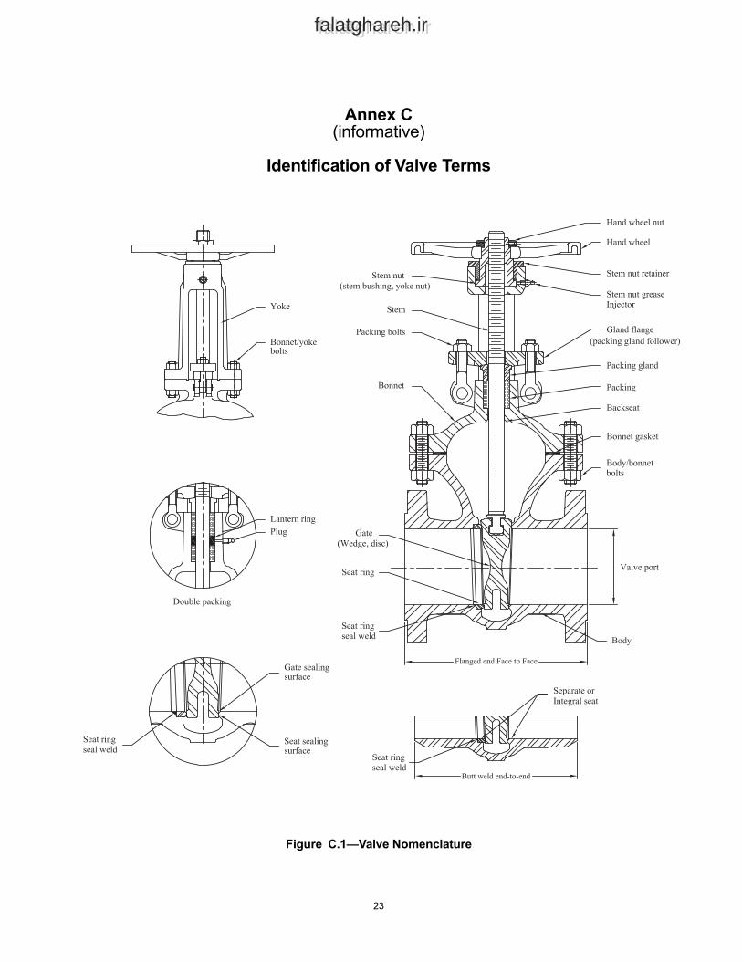
Annex C (informative) Identification of Valve Terms . . . . . . . . . . . . . . . . . . . . . . . . . . . . . . . . . . . . . . . . . . . . . . . . 23
Bibliography . . . . . . . . . . . . . . . . . . . . . . . . . . . . . . . . . . . . . . . . . . . . . . . . . . . . . . . . . . . . . . . . . . . . . . . . . . . . . . . . 24
Figures1 Identification of Terms . . . . . . . . . . . . . . . . . . . . . . . . . . . . . . . . . . . . . . . . . . . . . . . . . . . . . . . . . . . . . . . . . . . . 4
v
Contents
Page
falatghareh.irfalatghareh.ir
2 Types of Valve Gates. . . . . . . . . . . . . . . . . . . . . . . . . . . . . . . . . . . . . . . . . . . . . . . . . . . . . . . . . . . . . . . . . . . . . . 83 Wear Travel of a Wedge Gate . . . . . . . . . . . . . . . . . . . . . . . . . . . . . . . . . . . . . . . . . . . . . . . . . . . . . . . . . . . . . . . 9C.1 Valve Nomenclature . . . . . . . . . . . . . . . . . . . . . . . . . . . . . . . . . . . . . . . . . . . . . . . . . . . . . . . . . . . . . . . . . . . . . 23
Tables1 Minimum Thickness of Shell/Bonnet Wall, tm and Minimum Diameter of Stem, ds . . . . . . . . . . . . . . . . . . 52 Minimum Wear Travel and Maximum Stem Projection . . . . . . . . . . . . . . . . . . . . . . . . . . . . . . . . . . . . . . . . . . 93 Stuffing Box and Packing Dimensions . . . . . . . . . . . . . . . . . . . . . . . . . . . . . . . . . . . . . . . . . . . . . . . . . . . . . . 124 Materials for Parts . . . . . . . . . . . . . . . . . . . . . . . . . . . . . . . . . . . . . . . . . . . . . . . . . . . . . . . . . . . . . . . . . . . . . . . 14
vi

falatghareh.irfalatghareh.ir
falatghareh.irfalatghareh.ir
Corrosion-resistant, Bolted Bonnet Gate Valves—Flanged and Butt-welding Ends
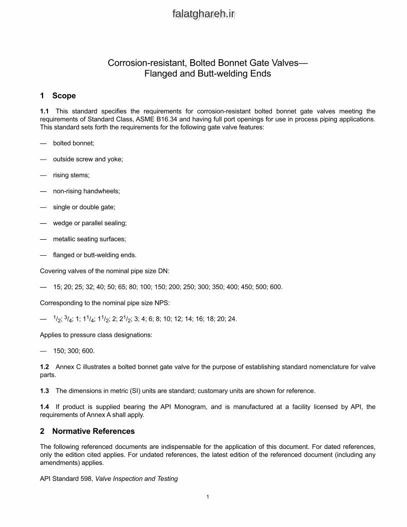
1 Scope
1.1 This standard specifies the requirements for corrosion-resistant bolted bonnet gate valves meeting the requirements of Standard Class, ASME B16.34 and having full port openings for use in process piping applications. This standard sets forth the requirements for the following gate valve features:
— bolted bonnet;
— outside screw and yoke;
— rising stems;
— non-rising handwheels;
— single or double gate;
— wedge or parallel sealing;
— metallic seating surfaces;
— flanged or butt-welding ends.
Covering valves of the nominal pipe size DN:
— 15; 20; 25; 32; 40; 50; 65; 80; 100; 150; 200; 250; 300; 350; 400; 450; 500; 600.
Corresponding to the nominal pipe size NPS:
— 1/2; 3/4; 1; 11/4; 11/2; 2; 21/2; 3; 4; 6; 8; 10; 12; 14; 16; 18; 20; 24.
Applies to pressure class designations:
— 150; 300; 600.
1.2 Annex C illustrates a bolted bonnet gate valve for the purpose of establishing standard nomenclature for valve parts.
1.3 The dimensions in metric (SI) units are standard; customary units are shown for reference.
1.4 If product is supplied bearing the API Monogram, and is manufactured at a facility licensed by API, the requirements of Annex A shall apply.
2 Normative References
The following referenced documents are indispensable for the application of this document. For dated references, only the edition cited applies. For undated references, the latest edition of the referenced document (including any amendments) applies.
API Standard 598, Valve Inspection and Testing
1
2 API STANDARD 603
falatghareh.irfalatghareh.ir
API Standard 600, Steel Gate Valves—Flanged and Butt-welding Ends, Bolted Bonnets
API Standard 602, Gate, Globe and Check Valves for Sizes DN 100 (NPS 4) and Smaller for the Petroleum and Natural Gas Industries
API Standard 624, Type Testing of Rising Stem Valves Equipped with Graphite Packing for Fugitive Emissions
ASME II 1, BPVC Section II-Materials-Part D-Properties-(Customary)
ASME IX, BPVC Section IX-Welding, Brazing, and Fusing Qualifications
ASME B1.1, Unified Inch Screw Threads (UN and UNR Thread Form)
ASME B1.5, Acme Screw Threads
ASME B1.8, Stub Acme Screw Threads
ASME B1.12, Class 5 Interference-Fit Thread
ASME B1.13M, Metric Screw Threads: M Profile
ASME B16.5, Pipe Flanges and Flanged Fittings: NPS 1/2 through NPS 24 Metric/Inch Standard
ASME B16.10, Face-to-Face and End-to-End Dimensions of Valves
ASME B16.20, Metallic Gaskets for Pipe Flanges: Ring-Joint, Spiral-Wound, and Jacketed
ASME B16.25, Buttwelding Ends
ASME B16.34, Valves—Flanged, Threaded, and Welding End
ASME B18.2.2, Nuts for General Applications: Machine Screw Nuts, Hex, Square, Hex Flange, and Coupling Nuts (Inch Series)
ASME B18.2.3.5M, Metric Hex Bolts
ASME B18.2.3.6M, Metric Heavy Hex Bolts
ASME B18.2.6M, Metric Fasteners for Use in Structural Applications
ASME B31.3, Process Piping
ASME B31T, Standard Toughness Requirements for Piping
ASTM A193/A193M 2, Standard Specification for Alloy-Steel and Stainless Steel Bolting for High Temperature or High Pressure Service and Other Special Purpose Applications
ASTM A194/A194M, Standard Specification for Carbon Steel, Alloy Steel, and Stainless Steel Nuts for Bolts for High Pressure or High Temperature Service, or Both
ASTM A439/A439M, Standard Specification for Austenitic Ductile Iron Castings
1 ASME International, 2 Park Avenue, New York, New York 10016, www.asme.org.2 ASTM International, 100 Bar Harbor Drive, P.O. Box C700, West Conshohocken, Pennsylvania 19428, www.astm.org.
CORROSION-RESISTANT, BOLTED BONNET GATE VALVES—FLANGED AND BUTT-WELDING ENDS 3
falatghareh.irfalatghareh.ir
AWS A5.13/A5.13M 3, Specification for Surfacing Electrodes for Shielded Metal Arc Welding
AWS A5.21/A5.21M, Specification for Bare Electrodes and Rods for Surfacing
ISO 5210 4, Industrial valves—Multi-turn valve actuator attachments
MSS SP-55 5, Quality Standard for Steel Castings for Valves, Flanges, Fittings, and Other Piping Components—Visual Method for Evaluation of Surface Irregularities
MSS SP-91, Guidelines for Manual Operation of Valves
MSS SP-102, Multi-Turn Valve Actuator Attachment—Flange and Driving Component Dimensions and Performance Characteristics
3 Terms and Definitions
For the purposes of this document, the following definitions apply.
3.1classAn alphanumeric designation that is used for reference purposes relating to valve pressure/temperature capability, taking into account valve material mechanical properties and valve dimensional characteristics. It comprises “Class” followed by a dimensionless whole number. The number following “Class” does not represent a measurable value and is not used for calculation purposes except where specified in this standard. The allowable pressure for a valve with a designated class number depends on the valve material and its application temperature and is to be found in pressure/temperature ratings tables.
3.2DNAn alphanumeric size designation that is common for piping system components and is used for reference purposes. It comprises the letters “DN” followed by a dimensionless number indirectly related to the physical size of the bore or outside diameter of the end connection as appropriate. The dimensionless number following “DN” does not represent a measurable value and is not used for calculation purposes except where specified.
3.3NPSAn alphanumeric size designation that is common for piping system components and is used for reference purposes. It comprises the letters “NPS” followed by a dimensionless number indirectly related to the physical size of the bore or outside diameter of the end connection as appropriate. The dimensionless number may also be used as a valve size identifier without the prefix “NPS.” The dimensionless size identification number does not represent a measurable value and is not used for calculation purposes.
3.4shellThe body, bonnet, and body-bonnet bolting which together constitute the pressure boundary of an API 603 valve.
3 American Welding Society, 8669 NW 36 Street, #130, Miami, Florida 33166-6672, www.aws.org.4 International Organization for Standardization, ISO Central Secretariat, Chemin de Blandonnet 8, CP 401, 1214 Vernier,
Geneva, Switzerland, www.iso.org.5 Manufacturers Standardization Society of the Valve and Fittings Industry, Inc., 127 Park Street, NE, Vienna, Virginia 22180-
4602, www.msshq.org.
4 API STANDARD 603
falatghareh.irfalatghareh.ir
4 Pressure/Temperature Ratings
4.1 Pressure/temperature ratings shall be in accordance with those specified in the tables of ASME B16.34 for Standard Class for both the applicable material specification and the applicable class.
4.2 Restrictions of temperature and concurrent pressure, or pressure and concurrent temperature (e.g., those imposed by special soft seals or trim materials) shall be marked on the valve identification plate (see Section 8).
4.3 The temperature used to determine the corresponding pressure rating shall be the maximum temperature of the pressure-containing shell of the valve. In general, this temperature is assumed to be the same as that of the contained fluid. The use of a pressure rating corresponding to a temperature other than that of the contained fluid is the responsibility of the user.
4.4 For temperatures below the lowest temperature listed in the ASME B16.34 pressure/temperature tables, the pressure rating shall be no greater than the rating listed for the lowest temperature. The use of valves at lower temperatures is the user’s responsibility, and consideration shall be given to the loss of ductility and impact strength per ASME B31.3 and ASME B31T. Additional information on service valves with body/bonnet extensions can be found in MSS SP-134 [1] and ISO 28921-1 [2].
4.5 Double-seated valves, in some design configurations, may be capable of trapping liquid in the center cavity of the valve when in the closed position. If subjected to an increase in temperature, an excessive build-up of pressure can occur, which may result in a pressure boundary failure. Where such a condition is possible, it is the responsibility of the user to provide or require to be provided adequate means (by design, installation, or operating procedures) for pressure relief of the center cavity.
5 Design
5.1 Body Wall Thickness
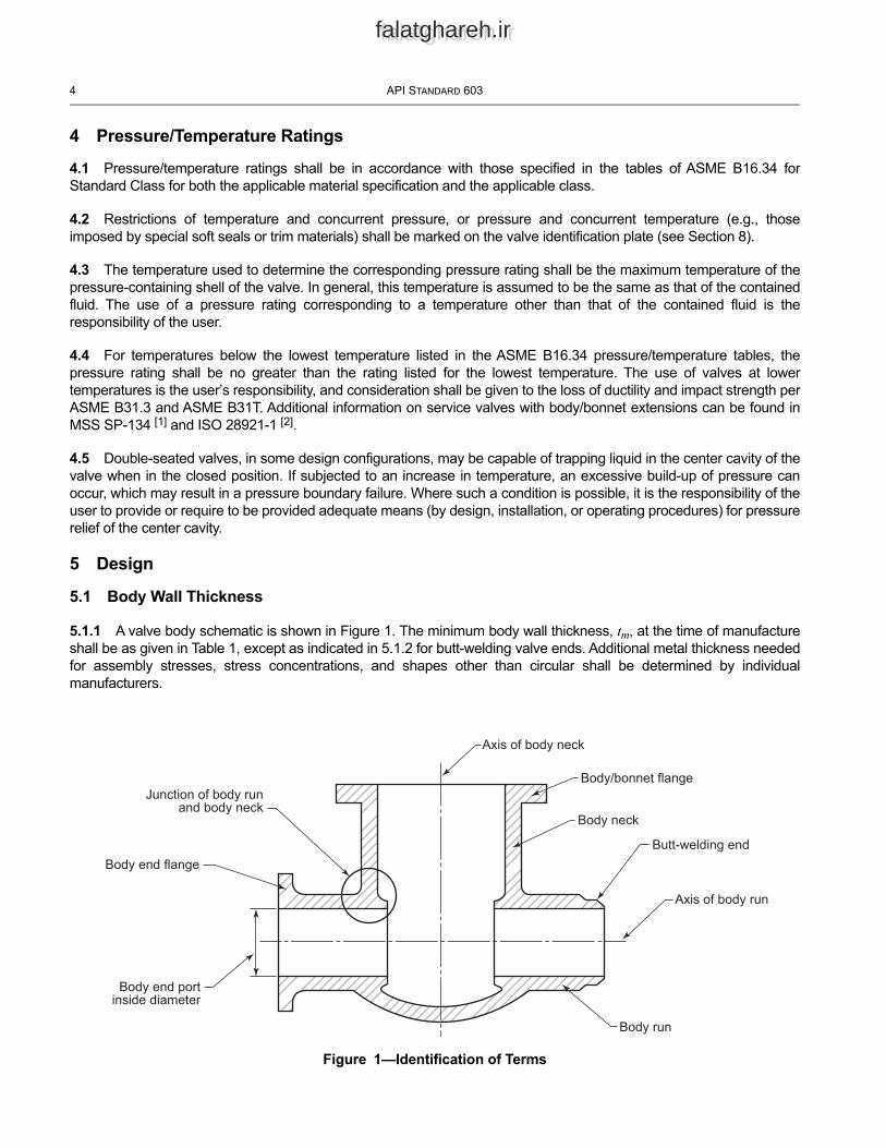
5.1.1 A valve body schematic is shown in Figure 1. The minimum body wall thickness, tm, at the time of manufacture shall be as given in Table 1, except as indicated in 5.1.2 for butt-welding valve ends. Additional metal thickness needed for assembly stresses, stress concentrations, and shapes other than circular shall be determined by individual manufacturers.
Figure 1—Identification of Terms
Junction of body runand body neck
Body end flange
Body end portinside diameter
Axis of body neck
Body/bonnet flange
Body neck
Butt-welding end
Axis of body run
Body run
CORROSION-RESISTANT, BOLTED BONNET GATE VALVES—FLANGED AND BUTT-WELDING ENDS 5
falatghareh.irfalatghareh.ir
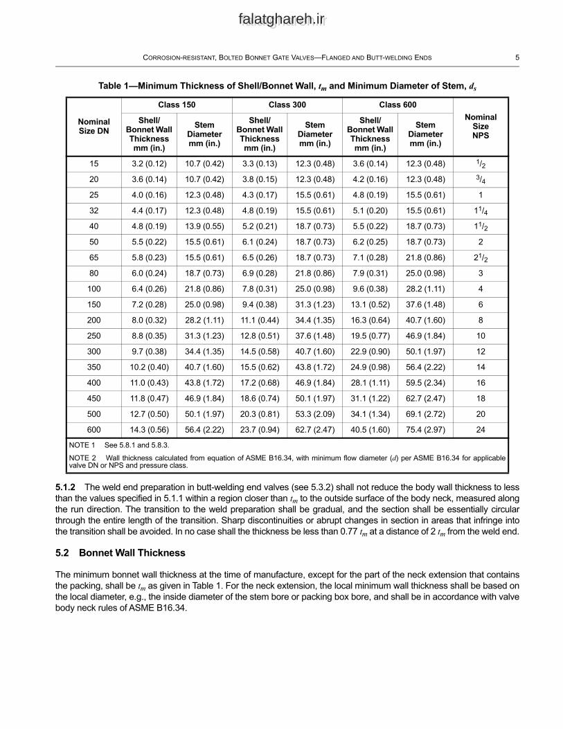
Table 1—Minimum Thickness of Shell/Bonnet Wall, tm and Minimum Diameter of Stem, ds
Nominal Size DN
Class 150 Class 300 Class 600Nominal
Size NPS
Shell/ Bonnet Wall Thickness mm (in.)
Stem Diameter mm (in.)
Shell/ Bonnet Wall Thickness mm (in.)
Stem Diameter mm (in.)
Shell/ Bonnet Wall Thickness mm (in.)
Stem Diameter mm (in.)
15 3.2 (0.12) 10.7 (0.42) 3.3 (0.13) 12.3 (0.48) 3.6 (0.14) 12.3 (0.48) 1/220 3.6 (0.14) 10.7 (0.42) 3.8 (0.15) 12.3 (0.48) 4.2 (0.16) 12.3 (0.48) 3/425 4.0 (0.16) 12.3 (0.48) 4.3 (0.17) 15.5 (0.61) 4.8 (0.19) 15.5 (0.61) 1
32 4.4 (0.17) 12.3 (0.48) 4.8 (0.19) 15.5 (0.61) 5.1 (0.20) 15.5 (0.61) 11/440 4.8 (0.19) 13.9 (0.55) 5.2 (0.21) 18.7 (0.73) 5.5 (0.22) 18.7 (0.73) 11/250 5.5 (0.22) 15.5 (0.61) 6.1 (0.24) 18.7 (0.73) 6.2 (0.25) 18.7 (0.73) 2
65 5.8 (0.23) 15.5 (0.61) 6.5 (0.26) 18.7 (0.73) 7.1 (0.28) 21.8 (0.86) 21/280 6.0 (0.24) 18.7 (0.73) 6.9 (0.28) 21.8 (0.86) 7.9 (0.31) 25.0 (0.98) 3
100 6.4 (0.26) 21.8 (0.86) 7.8 (0.31) 25.0 (0.98) 9.6 (0.38) 28.2 (1.11) 4
150 7.2 (0.28) 25.0 (0.98) 9.4 (0.38) 31.3 (1.23) 13.1 (0.52) 37.6 (1.48) 6
200 8.0 (0.32) 28.2 (1.11) 11.1 (0.44) 34.4 (1.35) 16.3 (0.64) 40.7 (1.60) 8
250 8.8 (0.35) 31.3 (1.23) 12.8 (0.51) 37.6 (1.48) 19.5 (0.77) 46.9 (1.84) 10
300 9.7 (0.38) 34.4 (1.35) 14.5 (0.58) 40.7 (1.60) 22.9 (0.90) 50.1 (1.97) 12
350 10.2 (0.40) 40.7 (1.60) 15.5 (0.62) 43.8 (1.72) 24.9 (0.98) 56.4 (2.22) 14
400 11.0 (0.43) 43.8 (1.72) 17.2 (0.68) 46.9 (1.84) 28.1 (1.11) 59.5 (2.34) 16
450 11.8 (0.47) 46.9 (1.84) 18.6 (0.74) 50.1 (1.97) 31.1 (1.22) 62.7 (2.47) 18
500 12.7 (0.50) 50.1 (1.97) 20.3 (0.81) 53.3 (2.09) 34.1 (1.34) 69.1 (2.72) 20
600 14.3 (0.56) 56.4 (2.22) 23.7 (0.94) 62.7 (2.47) 40.5 (1.60) 75.4 (2.97) 24
5.1.2 The weld end preparation in butt-welding end valves (see 5.3.2) shall not reduce the body wall thickness to less than the values specified in 5.1.1 within a region closer than tm to the outside surface of the body neck, measured along the run direction. The transition to the weld preparation shall be gradual, and the section shall be essentially circular through the entire length of the transition. Sharp discontinuities or abrupt changes in section in areas that infringe into the transition shall be avoided. In no case shall the thickness be less than 0.77 tm at a distance of 2 tm from the weld end.
5.2 Bonnet Wall Thickness
The minimum bonnet wall thickness at the time of manufacture, except for the part of the neck extension that contains the packing, shall be tm as given in Table 1. For the neck extension, the local minimum wall thickness shall be based on the local diameter, e.g., the inside diameter of the stem bore or packing box bore, and shall be in accordance with valve body neck rules of ASME B16.34.
NOTE 1 See 5.8.1 and 5.8.3.
NOTE 2 Wall thickness calculated from equation of ASME B16.34, with minimum flow diameter (d) per ASME B16.34 for applicable valve DN or NPS and pressure class.
6 API STANDARD 603
falatghareh.irfalatghareh.ir
5.3 Body
5.3.1 Flanged Ends
5.3.1.1 Body end flanges shall comply with the dimensional requirements of ASME B16.5. Unless otherwise specified, raised face end flanges shall be provided. The purchaser may specify a flange facing finish other than that specified in ASME B16.5.
5.3.1.2 Face-to-face dimensions shall be in accordance with ASME B16.10. Body end flanges and bonnet flanges shall be cast or forged integral with the body.
5.3.2 Butt-welding Ends
5.3.2.1 Butt-welding ends for valve sizes greater than DN 50 (NPS 2) shall conform to the requirements of ASME B16.25 and B16.34 for the bore specified for use without backing rings. Butt-welding ends for valves DN 50 (NPS 2) and smaller shall conform to the requirements of API 602. Conversion of a flanged end valve to a butt-welding valve for Class 300 and above may be permitted by agreement between the purchaser and manufacturer.
5.3.2.2 End-to-end dimensions for butt-welding end class-designated valves shall be in accordance with ASME B16.10, unless otherwise specified by the purchaser.
5.3.2.3 Short pattern butt-welding end bolted bonnet valves are not permitted.
5.3.3 Body Seats
5.3.3.1 The inside diameter of the seat opening shall not be less than that specified in ASME B16.34 for the applicable valve DN or NPS and pressure class.
5.3.3.2 Body seats may be separate or integral with the body. When hardfacing is furnished, it shall be applied as a weld overlay of AWS A5.13 ECoCr-A or AWS A 5.21 ERCoCr-A, except as provided in 6.2.2, and shall have a minimum finished thickness of 1.6 mm (0.06 in.).
5.3.3.3 Where separate seat rings are provided, they shall be shoulder- or bottom-seated, and either threaded or seal welded in place, except that for DN ≤ 50 (NPS ≤ 2) rolled or pressed-in seat rings may be used. Threaded seat rings shall be seal welded and shall be provided with lugs or slots to facilitate removal. The material used for seal welding shall provide the same corrosion resistance as the valve body material. Tack welding or stitch welding is not permitted.
5.3.3.4 Welding and any associated post-weld heat treatment shall be performed using qualified welders and established procedures in accordance with ASME Section IX and the principles of ASME Section II, Part D.
5.3.3.5 Body seat rings shall have adequate seating area surface and shall have edges equipped with a radius or chamfer as necessary, to prevent galling or any other damage to the gate when the valve is operated against pressure.
5.3.3.6 Sealing compounds or greases shall not be used when assembling seat rings; however, a light lubricant having a viscosity no greater than kerosene may be used to prevent galling of mating threaded surfaces.
5.4 Bonnet
5.4.1 When designing the stem, gland, backseat, and (where supplied) a lantern ring and/or spacer ring, the manufacturer shall consider the need for stem guiding, the prevention of packing extrusion, and avoidance of galling.
CORROSION-RESISTANT, BOLTED BONNET GATE VALVES—FLANGED AND BUTT-WELDING ENDS 7
falatghareh.irfalatghareh.ir
5.4.2 A machined conical or spherical backseat shall be provided in the bonnet to contact a corresponding seating surface on the valve stem. The backseat shall be either an integral surface or weld-deposited hardfacing with a minimum finished thickness of 1.6 mm (0.06 in.). Weld-deposited hardfacing is permissible as noted in 5.3.3.2 and as agreed upon by purchaser.
5.4.3 Bonnets shall be one-piece castings or forgings.
5.4.4 The gland bolting shall be secured to the bonnet so that the bolting is retained during repacking. When eyebolts are used, the eyebolt pin shall be anchored on both sides of the eyebolt. The anchors shall not include open slotted holes or be attached by fillet welds.
5.4.5 Tapped test openings shall be provided only if specified in the purchase order.
5.5 Bonnet-to-body Joint
5.5.1 The bonnet-to-body joint shall be a flange and gasket type.
5.5.2 For Class 150 valves, the bonnet-to-body joint shall be one of the following types illustrated in ASME B16.5.
— flat face;
— raised face;
— tongue and groove;
— spigot and recess (i.e., male and female);
— ring joint.
5.5.3 For valves having pressure class designation Class > 150, the bonnet-to-body joint shall be as in 5.5.2, except that the flat face joint is not permitted.
5.5.4 The bonnet flange gasket shall be one of the following:
— solid metal or grooved (profiled) metal gasket with graphite covering layers;
— metal ring joint with hardness criteria as specified in ASME B16.20;
— spiral wound metal gasket with filler and a centering/compression ring;
— spiral wound metal gasket with filler but without a centering/compression ring; to be used only in ‘tongue and groove’ or ‘spigot and recess’ joints that prevent the gasket spirals from unwinding or buckling.
For Class 150, the following are also acceptable:
— corrugated metal insert with graphite covering layers;
— when approved by the purchaser, flexible graphite sheet, reinforced with a stainless steel flat, perforated, tanged, or corrugated insert equipped with annular containment rings;
— when approved by the purchaser, other suitable facings may be used.
5.5.5 Except for Class 150, the gasket shall not extend beyond the inner edge of the bolt holes.
8 API STANDARD 603
falatghareh.irfalatghareh.ir
5.5.6 Except for Class 150 and all valve classes in sizes DN 65 (NPS 21/2) and smaller, the bonnet-to-body flange gasket shall be circular.
5.5.7 Bonnet and body flange nut bearing surfaces shall be parallel to the flange face within ± 1°. Spot-facing or back-facing required to meet the parallelism requirement shall be in accordance with ASME B16.5.
5.5.8 The bonnet-to-body joint shall be secured by a minimum of four bolts/cap screws that provide uniform spacing and load distribution. For valves DN 25 (NPS 1) and larger, through-bolts shall be used in the bonnet joint. For valves DN 20 (NPS 3/4) and smaller, through-bolts, headed bolts, or cap screws may be used. Cap screws, if used, shall be suitable for external wrenching only. The minimum stud bolt size for each valve size shall be as follows:
— M10 or 3/8 in. when DN ≤ 65 (NPS ≤ 21/2);
— M12 or 1/2 in. when 80 ≤ DN ≤ 200 (3 ≤ NPS ≤ 8);
— M16 or 5/8 in. when DN ≥ 250 (NPS ≥ 10).
5.5.9 The total cross-sectional area of the bolts in valve bonnet bolting shall be in accordance with the requirements of ASME B16.34.
5.5.10 At assembly, gasket contact surfaces shall be free of sealing compounds. A light coating of a lubricant, no heavier than kerosene, may be applied if needed to assist in proper gasket assembly.
5.6 Gate
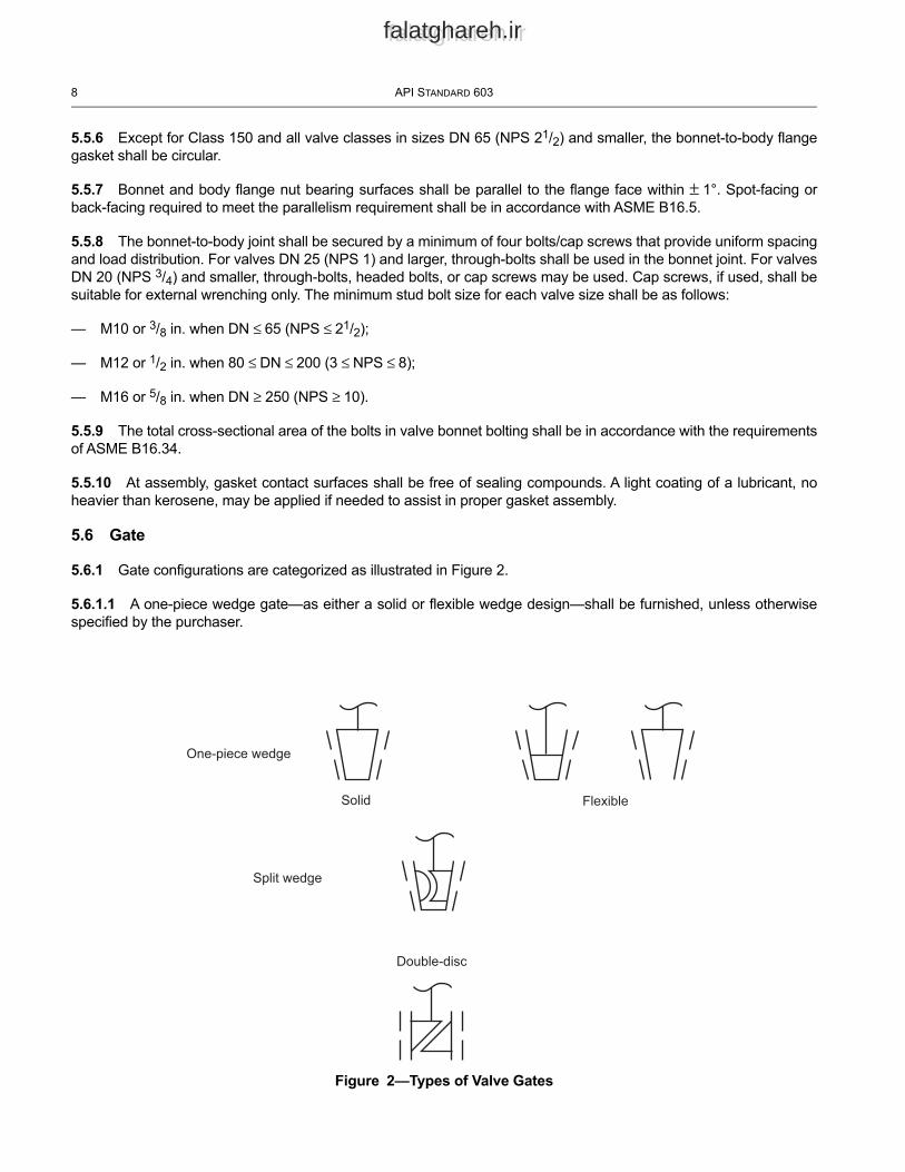
5.6.1 Gate configurations are categorized as illustrated in Figure 2.
5.6.1.1 A one-piece wedge gate—as either a solid or flexible wedge design—shall be furnished, unless otherwise specified by the purchaser.
Figure 2—Types of Valve Gates
FlexibleSolid
One-piece wedge
Split wedge
Double-disc
CORROSION-RESISTANT, BOLTED BONNET GATE VALVES—FLANGED AND BUTT-WELDING ENDS 9
falatghareh.irfalatghareh.ir
5.6.1.2 A two-piece split wedge gate or parallel seat double-disc gate may be furnished when specified by the purchaser. A split wedge gate consists of two independent seating parts that conform to the body seats when closed. The split wedge shall be designed so that the pieces cannot become separated, regardless of the gate position or valve orientation. A double-disc gate shall have a spreading mechanism (i.e., a wedging device or spring) that forces the two parallel discs to the body seats when closed.
5.6.2 In the open position, the gate shall completely clear the valve seat openings (except for a double-disc gate).
5.6.3 Gate seating surfaces shall be integral or faced with weld metal. Unless specified, hardfaced seating surfaces are not required. Finished thickness of any facing material shall be not less than 1.6 mm (0.06 in.)
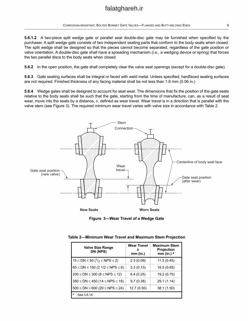
5.6.4 Wedge gates shall be designed to account for seat wear. The dimensions that fix the position of the gate seats relative to the body seats shall be such that the gate, starting from the time of manufacture, can, as a result of seat wear, move into the seats by a distance, h, defined as wear travel. Wear travel is in a direction that is parallel with the valve stem (see Figure 3).
Figure 3—Wear Travel of a Wedge Gate
StemConnection
Gate seat position(new valve)
Weartravel
New Seats Worn Seats
Gate seat position (after wear)
Centerline of body seat face
The required minimum wear travel varies with valve size in accordance with Table 2.
Table 2—Minimum Wear Travel and Maximum Stem Projection
Valve Size RangeDN (NPS)
Wear Travelh
mm (in.)
Maximum Stem Projectionmm (in.) a
15 ≤ DN ≤ 50 (1/2 ≤ NPS ≤ 2) 2.3 (0.09) 11.5 (0.45)
65 ≤ DN ≤ 150 (2 1/2 ≤ NPS ≤ 6) 3.3 (0.13) 16.5 (0.65)
200 ≤ DN ≤ 300 (8 ≤ NPS ≤ 12) 6.4 (0.25) 19.2 (0.75)
350 ≤ DN ≤ 450 (14 ≤ NPS ≤ 18) 9.7 (0.38) 29.1 (1.14)
500 ≤ DN ≤ 600 (20 ≤ NPS ≤ 24) 12.7 (0.50) 38.1 (1.50)a See 5.8.14
10 API STANDARD 603
falatghareh.irfalatghareh.ir
5.6.5 The body and gate shall have guide surfaces to minimize wear of the gate seats during operation of the valve, to accurately position the gate throughout the travel distance to its seat, and to ensure alignment of the gate and stem in all orientations, without gate binding or galling. The possible loss of metal due to corrosion, erosion, abrasive wear, or a combination of these factors shall be considered in the design of the body and gate guide surfaces. Wedge guides and/or body guides need not be hardfaced unless specified in the purchase order, or when required to allow for proper valve operation in any orientation, including effects of wear or galling. Wedge guides and/or body guides shall not protrude beyond the seat rings into the port area of the valve.
5.7 Yoke
5.7.1 The yoke may be either an integral part of the bonnet or a separate part.
5.7.2 Yokes that are separate shall have yoke-to-bonnet mating surfaces machined so as to assure a proper bearing assembly interface. Separate yokes shall be bolted to the bonnet with through-bolts.
5.7.3 The yoke-to-stem nut bearing surfaces shall be machined flat and parallel. A lubricating fitting shall be provided for the bearing surfaces.
5.8 Stem and Stem Nut
5.8.1 The minimum stem diameter, ds measured at the section that passes through the packing, shall be in accordance with Table 1. The actual stem diameter shall take into account the valve design details and the stem materials’ strength characteristics. The stem strength shall be considered when calculating the maximum input force from the handwheel, the chain wheel operator (if equipped) and the gearbox (if equipped), in accordance with MSS SP-91.
5.8.2 The stem shall have a gate attachment means at one end and an external, trapezoidal style thread form at the other. Stem nuts shall be used for handwheel attachment and for driving the operating stem thread. The handwheel-to-stem nut connection shall be secured to prevent loosening.
5.8.3 The stem-to-stem nut threads shall be of trapezoidal form as specified in ASME B1.5 or ASME B1.8, (minor modifications are permitted for either thread) with nominal dimensional variations allowed. The major diameter of the thread may be less by a maximum of 1.6 mm (0.06 in.) than the diameter of the stem that passes through the packing. Stem threads shall be left-handed so that a direct operated handwheel rotated in a clockwise direction closes the valve. For manually operated valves, the minimum thread engagement length between the stem and the stem nut shall be one-and-one-half times the stem diameter.
5.8.4 The stem shall be one-piece wrought material. A stem that is a welded fabrication or threaded assembly shall not be provided.
5.8.5 The stem surface area in contact with the packing shall have a surface finish, Ra, of 0.80 µm (32 µin.) or smoother.
5.8.6 Out-of-straightness of the entire length of the stem shall not exceed 0.001 mm/mm (0.001 in./in.)
5.8.7 The stem end that connects to a gate shall be in the form of a “T,” except that for a double-disc gate, the end connection may be threaded.
5.8.8 The stem connection shall be designed to prevent the stem from turning or from becoming disengaged from the gate while the valve is in service.
5.8.9 The stem design shall be such that the strength of the stem-to-gate connection and the part of the stem within the valve pressure boundary shall, under axial load, exceed the strength of the stem at the root of the operating thread.
CORROSION-RESISTANT, BOLTED BONNET GATE VALVES—FLANGED AND BUTT-WELDING ENDS 11
falatghareh.irfalatghareh.ir
5.8.10 The one-piece stem shall include a raised conical or spherical surface that seats against the bonnet backseat when the gate is at its full open position.
Warning—Adding or replacing packing while the valve is under pressure is not recommended.
5.8.11 The yoke shall retain the stem nut which links the handwheel to the stem. For valves larger than DN 150 (NPS 6) Class 150, DN 100 (NPS 4) Class 300 or DN 50 (NPS 2) Class 600, the stem nut arrangement shall be designed to:
a) Permit the removal of the handwheel, without allowing the stem and gate to drop into the closed position, if the handwheel is removed when the valve is in the open position.
b) Allow the stem nut to be replaced, with the stem secured, without affecting the pressure-retaining capability of the bonnet assembly. However, replacement under pressure is not recommended.
5.8.12 Valves shall have a stem operated by a rotating stem nut mounted at the top of the yoke. The stem nut shall have a hexagonal shank, a round shank with a keyway, or another drive of equivalent strength and durability for attachment to the handwheel.
5.8.13 When the stem nut is retained in the yoke by means of a threaded bushing, the bushing shall be secured in place using either a lock weld or a positive mechanical lock. Locking by simple metal upsetting such as peening or staking is not permitted.
5.8.14 The closed-position stem thread projection beyond the stem nut on a new handwheel operated valve shall be equal to or greater than the minimum wear travel values listed in Table 2. The maximum stem projection distance shall be as indicated in Table 2.
5.8.15 Valves DN 150 (NPS ≥ 6) and pressure class equal to Class 600, shall be furnished with stem nuts having ball or roller bearings.
5.9 Packing and Packing Box
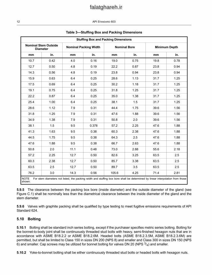
5.9.1 The packing may be either square, rectangular, or trapezoidal in cross-section. The nominal radial width of the packing shall be in accordance with Table 3.
5.9.2 The nominal depth of the packing box, below the packing box entry chamfer, shall accommodate a minimum of five uncompressed rings of packing. Unless otherwise specified by the purchaser, the packing box surface area in contact with the packing material shall have a surface finish, Ra, of 4.5 μm (175 μin.) or smoother. The stuffing box dimensions shall meet those specified in Table 3. The bottom of the packing box shall be flat. The remaining adjustment length of the packing gland, with the gland tight and after final hydrostatic testing, shall be greater than one and one-half times the packing width specified in Table 3.
5.9.3 A gland and a separate gland flange shall be provided for packing compression. The gland flange shall have two holes to receive the gland bolting. Slots for gland flange bolts shall not be used. The gland and gland flange shall be self-aligning. The gland shall have a shoulder at its outer edge so as to prevent complete entry of the gland into the packing box.
5.9.4 A lantern ring shall be furnished only if specified in the purchase order. In order to accommodate the lantern ring, the stuffing box depth shall be at least equivalent to that of a minimum of three uncompressed rings of packing above the lantern ring and three uncompressed rings of packing below the lantern ring, plus the length of the lantern ring.
12 API STANDARD 603
falatghareh.irfalatghareh.ir
Table 3—Stuffing Box and Packing Dimensions
Stuffing Box and Packing Dimensions
Nominal Stem Outside Diameter Nominal Packing Width Nominal Bore Minimum Depth
mm in. mm in. mm in. mm in.
10.7 0.42 4.0 0.16 19.0 0.75 19.8 0.78
12.7 0.50 4.8 0.19 22.2 0.87 23.8 0.94
14.3 0.56 4.8 0.19 23.8 0.94 23.8 0.94
15.9 0.63 6.4 0.25 28.6 1.13 31.7 1.25
17.5 0.69 6.4 0.25 30.2 1.18 31.7 1.25
19.1 0.75 6.4 0.25 31.8 1.25 31.7 1.25
22.2 0.87 6.4 0.25 35.0 1.38 31.7 1.25
25.4 1.00 6.4 0.25 38.1 1.5 31.7 1.25
28.6 1.12 7.9 0.31 44.4 1.75 39.6 1.56
31.8 1.25 7.9 0.31 47.6 1.88 39.6 1.56
34.9 1.38 7.9 0.31 50.8 2.0 39.6 1.56
38.1 1.5 9.5 0.378 57.2 2.25 47.6 1.88
41.3 1.63 9.5 0.38 60.3 2.38 47.6 1.88
44.5 1.75 9.5 0.38 64.3 2.5 47.6 1.88
47.6 1.88 9.5 0.38 66.7 2.63 47.6 1.88
50.8 2.0 11.1 0.48 73.0 2.88 55.6 2.18
57.2 2.25 12.7 0.50 82.6 3.25 63.5 2.5
60.3 2.38 12.7 0.50 85.7 3.38 63.5 2.5
63.5 2.5 12.7 0.50 89.7 3.5 63.5 2.5
76.2 3.0 14.3 0.56 105.6 4.25 71.4 2.81
5.9.5 The clearance between the packing box bore (inside diameter) and the outside diameter of the gland (see Figure C.1) shall be nominally less than the diametrical clearance between the inside diameter of the gland and the stem diameter.
5.9.6 Valves with graphite packing shall be qualified by type testing to meet fugitive emissions requirements of API Standard 624.
5.10 Bolting
5.10.1 Bolting shall be standard inch series bolting, except if the purchaser specifies metric series bolting. Bolting for the bonnet-to-body joint shall be continuously threaded stud bolts with heavy, semi-finished hexagon nuts that are in accordance with ASME B18.2.2 or ASME B18.2.6M. Headed bolts (ASME B18.2.3.5M, ASME B18.2.3.6M) are permitted, but shall be limited to Class 150 in sizes DN 200 (NPS 8) and smaller and Class 300 in sizes DN 150 (NPS 6) and smaller. Cap screws may be utilized for bonnet bolting for valves DN 20 (NPS 3/4) and smaller.
5.10.2 Yoke-to-bonnet bolting shall be either continuously threaded stud bolts or headed bolts with hexagon nuts.
NOTE For stem diameters not listed, the packing width and stuffing box bore shall be determined by linear interpolation from those shown.
CORROSION-RESISTANT, BOLTED BONNET GATE VALVES—FLANGED AND BUTT-WELDING ENDS 13
falatghareh.irfalatghareh.ir
5.10.3 Gland bolts shall be hinged eyebolts, headed bolts, stud bolts or studs. Hexagon nuts shall be used.
5.10.4 Bolting with diameters M24 (1 in.) and smaller shall have coarse (UNC) threads or the most nearly corresponding metric threads. Bolting with diameters larger than M24 (1 in.) shall be 8-thread series (8UN) or the most nearly corresponding metric threads. Bolt threads shall be Class 2A and nut threads shall be Class 2B, in accordance with ASME B1.1. Studs used for gland bolting shall use a Class 5 interference fit conforming to ASME B1.12. When metric bolting is used, metric bolt threads shall be tolerance Class 6g and nuts tolerance Class 6H, in accordance with ASME B1.13M.
5.11 Operation
5.11.1 Unless otherwise specified by the purchaser, the valve shall be supplied with a direct-operated handwheel that opens the valve when turned in a counter-clockwise direction.
5.11.2 The handwheel shall be a spoke-rim type with a maximum of six spokes and shall be free from burrs and sharp edges. Unless otherwise specified, the handwheel shall be a one-piece casting or forging, or a multi-piece carbon steel fabrication that includes other carbon steel product forms. Fabricated handwheels shall have strength and toughness characteristics comparable to that of handwheels made as one-piece castings or forgings.
5.11.3 The handwheel shall be marked with the word "OPEN" and an arrow pointing in the direction of the opening, except when the handwheel size makes such marking impractical.
5.11.4 The handwheel shall be retained on the stem nut by a threaded handwheel nut.
5.11.5 If operation by a chain wheel, gearbox or power actuator is to be added to the valve, the purchaser shall specify the following, as applicable:
— the dimension from the centerline of the valve stem or gear input shaft to the bottom of the chain loop (for chain wheel operation only);
— spur or bevel gear and the position of gearing handwheel relative to the pipe axis;
— electric, hydraulic, pneumatic, or other actuator type;
— maximum service temperature and pressure differential across the valve disc;
— maximum rim pull;
— power supply attributes for power actuators (including maximum differential pressure).
5.11.6 Valve-to-gear-box or power actuator flange mating dimensions shall be according to ISO 5210 or MSS-SP- 102 or shall comply with the purchaser’s specifications.
5.12 Bypasses and Other Auxiliary Connections
Auxiliary connections and tapped test openings to the body and/or bonnet, such as drains, shall be furnished only if specified in the purchase order. The design and construction of the joint and the piping of auxiliary connections shall conform to the requirements of ASME B16.34. When required for valve DN 50 (NPS 2) or larger, auxiliary connections shall be sized and located as specified in ASME B16.34. The size and location of auxiliary connections shall be indicated in the purchase order.
14 API STANDARD 603
falatghareh.irfalatghareh.ir
6 Materials
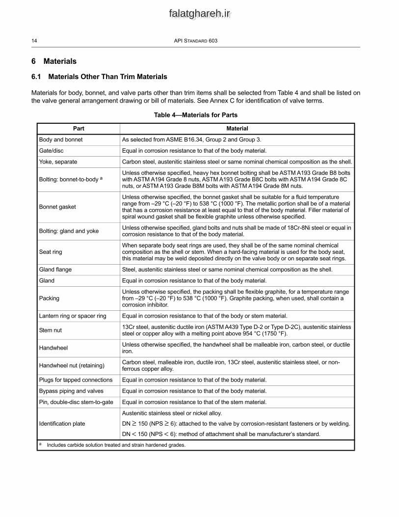
6.1 Materials Other Than Trim Materials
Materials for body, bonnet, and valve parts other than trim items shall be selected from Table 4 and shall be listed on the valve general arrangement drawing or bill of materials. See Annex C for identification of valve terms.
Table 4—Materials for Parts
Part Material
Body and bonnet As selected from ASME B16.34, Group 2 and Group 3.
Gate/disc Equal in corrosion resistance to that of the body material.
Yoke, separate Carbon steel, austenitic stainless steel or same nominal chemical composition as the shell.
Bolting: bonnet-to-body aUnless otherwise specified, heavy hex bonnet bolting shall be ASTM A193 Grade B8 bolts with ASTM A194 Grade 8 nuts, ASTM A193 Grade B8C bolts with ASTM A194 Grade 8C nuts, or ASTM A193 Grade B8M bolts with ASTM A194 Grade 8M nuts.
Bonnet gasketUnless otherwise specified, the bonnet gasket shall be suitable for a fluid temperature range from –29 °C (–20 °F) to 538 °C (1000 °F). The metallic portion shall be of a material that has a corrosion resistance at least equal to that of the body material. Filler material of spiral wound gasket shall be flexible graphite unless otherwise specified.
Bolting: gland and yoke Unless otherwise specified, gland bolts and nuts shall be made of 18Cr-8Ni steel or equal in corrosion resistance to that of the body material.
Seat ringWhen separate body seat rings are used, they shall be of the same nominal chemical composition as the shell or stem. When a hard-facing material is used for the body seat, this material may be weld deposited directly on the valve body or on separate seat rings.
Gland flange Steel, austenitic stainless steel or same nominal chemical composition as the shell.
Gland Equal in corrosion resistance to that of the body material.
PackingUnless otherwise specified, the packing shall be flexible graphite, for a temperature range from –29 °C (–20 °F) to 538 °C (1000 °F). Graphite packing, when used, shall contain a corrosion inhibitor.
Lantern ring or spacer ring Equal in corrosion resistance to that of the body or stem material.
Stem nut 13Cr steel, austenitic ductile iron (ASTM A439 Type D-2 or Type D-2C), austenitic stainless steel or copper alloy with a melting point above 954 °C (1750 °F).
Handwheel Unless otherwise specified, the handwheel shall be malleable iron, carbon steel, or ductile iron.
Handwheel nut (retaining) Carbon steel, malleable iron, ductile iron, 13Cr steel, austenitic stainless steel, or non-ferrous copper alloy.
Plugs for tapped connections Equal in corrosion resistance to that of the body material.
Bypass piping and valves Equal in corrosion resistance to that of the body material.
Pin, double-disc stem-to-gate Equal in corrosion resistance to that of the stem material.
Identification plate
Austenitic stainless steel or nickel alloy.
DN ≥ 150 (NPS ≥ 6): attached to the valve by corrosion-resistant fasteners or by welding.
DN < 150 (NPS < 6): method of attachment shall be manufacturer’s standard.a Includes carbide solution treated and strain hardened grades.
CORROSION-RESISTANT, BOLTED BONNET GATE VALVES—FLANGED AND BUTT-WELDING ENDS 15
falatghareh.irfalatghareh.ir
6.2 Trim
6.2.1 The trim comprises the following:
a) the stem;
b) body seating surface;
c) gate seating surface;
d) small internal parts that normally contact the service fluid (i.e., stem connections, internal pins or screws, and the spreading mechanism of a double-disc valve).
6.2.2 The standard valve trim parts shall be made of a material with the same nominal chemical composition as the valve body and bonnet. Alternate trims and overlays (including those referenced in API 600 and AWS A5.13 ECoCr-E and AWS A5.21 ECoCr-E hardfacing) can be supplied by agreement between purchaser and manufacturer.
7 Testing, Inspection, and Examination
7.1 Inspection and Examination
7.1.1 The valve manufacturer shall examine each valve to assure compliance to this standard.
7.1.2 If inspection by the purchaser is specified in the purchase order, inspection shall be in accordance with API 598. Examination by the manufacturer shall be as specified in API 598.
7.1.3 Cast surfaces of pressure boundary parts shall be visually inspected in accordance with MSS SP-55.
7.2 Pressure Tests
Each valve shall be pressure tested as specified in API 598.
7.3 Repairs of Defects
Defects in the shell of a cast or forged valve that are revealed by inspection or testing shall be repaired as permitted by the most nearly applicable ASTM cast or forged material specification listed in ASME B16.34.
7.4 Supplementary Requirements
Supplementary examination and testing (such as alloy verification [Positive Material Identification], corrosion testing, Nondestructive Examination requirements, or other types) are required when specified in the purchase order.
8 Marking
8.1 General
Valves shall be marked in accordance with the requirements of ASME B16.34, except that the nameplate shall include the designation “API 603 E9” in addition to the designation ASME B16.34. When special trim, packing or gasket materials other than graphite are used, pressure/temperature limitations shall be noted on the nameplate per ASME B16.34. Valves with packing or gasket materials other than graphite shall have an additional tag in the packing or gasket area to indicate non-graphitic material being used.
16 API STANDARD 603
falatghareh.irfalatghareh.ir
8.2 Marking for Unidirectional Valves
Valves with a center cavity relief shall have a flow arrow pointing downstream based on the center cavity relief to the high pressure side (inlet side) unless otherwise specified in the purchase order. The flow direction arrow shall either be cast, forged, or stamped into the valve body outer wall, or a separate identification plate shall be permanently attached to the body.
9 Preparation for Shipment
9.1 Coatings
9.1.1 Except for the handwheel or non-corrosion resistant material parts, valve parts shall not be painted.
9.2 Openings
9.2.1 Valve end flanges and welding ends shall be blanked to protect the gasket surfaces or welding ends and the valve internals during shipment and storage. The protective covers shall be made of wood, wood fiber, plastic, or metal and shall be securely attached to the valve ends by bolts, steel straps, steel clips, or suitable friction-locking devices. The protective cover surface in direct contact with the flange sealing surface shall not be of a porous material which allows moisture to accumulate on the sealing surface. Covers shall be designed so that the valve cannot be installed without the removal of the protective cover.
9.2.2 Tapped connections shall be fitted with fully tightened and threaded solid plugs.
9.3 Gate Position
The valve shall be shipped with the gate closed and with the stem threads lubricated.
9.4 Stem Packing
The valve shall be shipped with the lantern ring, if specified, and the packing installed (see 5.9.2). Unless specified otherwise by the purchaser, the packing gland bolts shall be tightened for shipment.
9.5 Packaging
9.5.1 Unless export packaging is specified in the purchase order, valves may be shipped loose, palletized, or packed in a box or crate.
9.5.2 When export packaging is specified in the purchase order, valves shall be shipped individually or collectively in wooden boxes or crates in a manner that will prevent shifting within the package.
9.6 Purchase Order Information
Items marked with an asterisk in Annex B are considered an integral part of this standard and shall be specified by the purchaser.
falatghareh.irfalatghareh.ir
Annex A(informative)
API Monogram ProgramUse of the API Monogram by Licensees
A.1 Scope
A.1.1 Applicability
This annex is normative (mandatory) for products supplied bearing the API Monogram and manufactured at a facility licensed by API; for all other instances it is not applicable.
A.1.2 General
The API Monogram® is a registered certification mark owned by the American Petroleum Institute (API) and authorized for licensing by the API Board of Directors. Through the API Monogram Program, API licenses product manufacturers to apply the API Monogram to products that comply with product specifications and that have been manufactured under a quality management system that meets the requirements of API Q1. API maintains a complete, searchable list of all Monogram licensees on the API Composite List website (http://www.api.org/compositelist).
The application of the API Monogram and license number on products constitutes a representation and warranty by the licensee to API and to purchasers of the products that, as of the date indicated, the products were manufactured under a quality management system conforming to the requirements of API Q1 and that the product conforms in every detail with the applicable standard(s) or product specification(s). API Monogram program licenses are issued only after an on-site audit has verified that an organization has implemented and continually maintained a quality management system that meets the requirements of API Q1, and that the resulting products satisfy the requirements of the applicable API product specification(s) and/or standard(s). Although any manufacturer may claim that its products meet API product requirements without monogramming them, only manufacturers with a license from API can apply the API Monogram to their products.
Together with the requirements of the API Monogram license agreement, this annex establishes the requirements for those organizations that wish to voluntarily obtain an API license to provide API monogrammed products that satisfy the requirements of the applicable API product specification(s) and/or standard(s) and API Monogram Program requirements.
For information on becoming an API Monogram Licensee, please contact API, Certification Programs, 1220 L Street NW, Washington, DC 20005 or call (202) 682-8145 or by email at [email protected].
A.2 Normative References
In addition to the referenced standards listed earlier in this document, this annex references the following standard:
API Specification Q1, Specification for Quality Management System Requirements for Manufacturing Organizations for the Petroleum and Natural Gas Industry
For Licensees under the Monogram Program, the latest version of this document shall be used. The requirements identified therein are mandatory.
17
18 API STANDARD 603
falatghareh.irfalatghareh.ir
A.3 API Monogram Program: Licensee Responsibilities
A.3.1 Monogram Program Requirements
For all organizations desiring to acquire and maintain a license to use the API Monogram, conformance with the following shall be required at all times:
a) quality management system requirements of API Q1;
b) API Monogram Program requirements of API Q1, Annex A;
c) requirements contained in the API product specification(s) to which the organization is licensed;
d) requirements contained in the API Monogram Program License Agreement.
A.3.2 Control of the Application and Removal of the API Monogram
Each licensee shall control the application and removal of the API Monogram in accordance with the following:
a) products that do not conform to API-specified requirements shall not bear the API Monogram;
b) each licensee shall develop and maintain an API Monogram marking procedure that documents the marking/monogramming requirements specified by this annex and any applicable API product specification(s) and/or standard(s). The marking procedure shall:
1) define the authority responsible for the application and removal of the API Monogram and license number;
2) define the method(s) used to apply the Monogram and license number;
3) identify the location on the product where the API Monogram and license number are to be applied;
4) require the application of the date of manufacture of the product in conjunction with the use of the API Monogram and license number;
5) require that the date of manufacture, at a minimum, be two digits representing the month and two digits representing the year (e.g., 05-12 for May 2012) unless otherwise stipulated in the applicable API product specification(s) or standard(s);
6) define the application of all other required API product specification(s) and/or standard(s) marking requirements.
c) only an API licensee shall apply the API Monogram and its designated license number to API monogrammable products;
d) the API Monogram and license number, when issued, are site-specific and subsequently the API Monogram shall only be applied at that site-specific licensed facility location;
e) the API Monogram may be applied at any time appropriate during the production process but shall be removed in accordance with the licensee’s API Monogram marking procedure if the product is subsequently found to be out of conformance with any of the requirements of the applicable API product specification(s) and/or standard(s) and API Monogram Program.
For certain manufacturing processes or types of products, alternative API Monogram marking procedures may be acceptable. Requirements for alternative API Monogram marking are detailed in the API Monogram Program
CORROSION-RESISTANT, BOLTED BONNET GATE VALVES—FLANGED AND BUTT-WELDING ENDS 19
falatghareh.irfalatghareh.ir
Alternative Marking of Products License Agreement, available on the API Monogram Program website at https://www.api.org/~/media/Files/Certification/Monogram-APIQR/0_API-Monogram-APIQR/Resources/API-Monogram-Alt-Marking-Agreement_Rev-8_FM-011_Modified-20180601.pdf.
A.3.3 Design and Design Documentation
Each licensee and/or applicant for licensing shall maintain current design documentation as identified in API Q1 for all of the applicable products that fall under the scope of each Monogram license. The design document information shall provide objective evidence that the product design meets the requirements of the applicable and most current API product specification(s) and/or standard(s). The design documentation shall be made available during API audits of the facility.
In specific instances, the exclusion of design activities is allowed under the Monogram Program, as detailed in Advisory #6, available on API Monogram Program website at https://www.api.org/products-and-services/api-monogram-and-apiqr/advisories-updates.
A.3.4 Manufacturing Capability
The API Monogram Program is designed to identify facilities that have demonstrated the ability to manufacture equipment that conforms to API specifications and/or standards. API may refuse initial licensing or suspend current licensing based on a facility’s level of manufacturing capability. If API determines that an additional review is warranted, API may perform additional audits (at the organization’s expense) of any subcontractors to ensure their conformance with the requirements of the applicable API product specification(s) and/or standard(s).
A.3.5 Use of the API Monogram in Advertising
An API Monogram licensee shall not use the API Monogram and/or license number on letterheads, buildings or other structures, websites, or in any advertising without an express statement of fact describing the scope of Licensee’s authorization (license number and product specification). The Licensee should contact API for guidance on the use of the API Monogram other than on products.
A.4 Product Marking Requirements
A.4.1 General
These marking requirements shall apply only to those API Licensees wishing to mark applicable products in conjunction with the requirements of the API Monogram Program.
A.4.2 Product Specification Identification
Manufacturers shall mark products as specified by the applicable API specifications or standards. Marking shall include reference to the applicable API specification and/or standard. Unless otherwise specified, reference to the API specifications and/or standards shall be, as a minimum, “API [Document Number]” (e.g., API 6A or API 600). Unless otherwise specified, when space allows, the marking may include use of “Spec” or “Std,” as applicable (e.g., API Spec 6A or API Std 600).
A.4.3 Units
Products shall be marked with units as specified in the API specification and/or standard. If not specified, equipment shall be marked with U.S. customary (USC) units. Use of dual units [USC units and metric (SI) units] may be acceptable, if such units are allowed by the applicable product specification and/or standard.
20 API STANDARD 603
falatghareh.irfalatghareh.ir
A.4.4 Nameplates
Nameplates, when applicable, shall be made of a corrosion-resistant material unless otherwise specified by the API specification and/or standard. Nameplate shall be located as specified by the API specification and/or standard. If the location is not specified, then the licensee shall develop and maintain a procedure detailing the location to which the nameplate shall be applied. Nameplates may be attached at any time during the manufacturing process.
The API Monogram and license number shall be marked on the nameplate, in addition to the other product marking requirements specified by the applicable product specification and/or standard.
A.4.5 License Number
The API Monogram license number shall not be used unless it is marked in conjunction with the API Monogram. The license number shall be used in close proximity to the API Monogram.
A.5 API Monogram Program: Nonconformance Reporting
API solicits information on products that are found to be nonconforming with API specified requirements, as well as field failures (or malfunctions), which are judged to be caused by either specification and/or standard deficiencies or nonconformities against API specified requirements. Customers are requested to report to API all problems with API monogrammed products. A nonconformance may be reported using the API Nonconformance Reporting System available at http://ncr.api.org/ncr.aspx.
falatghareh.irfalatghareh.ir
Annex B(normative)
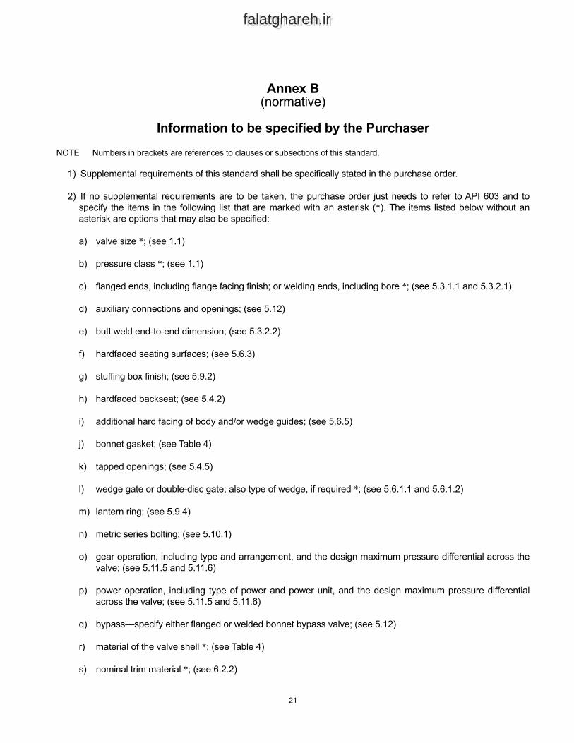
Information to be specified by the PurchaserNOTE Numbers in brackets are references to clauses or subsections of this standard.
1) Supplemental requirements of this standard shall be specifically stated in the purchase order.
2) If no supplemental requirements are to be taken, the purchase order just needs to refer to API 603 and to specify the items in the following list that are marked with an asterisk (*). The items listed below without an asterisk are options that may also be specified:
a) valve size *; (see 1.1)
b) pressure class *; (see 1.1)
c) flanged ends, including flange facing finish; or welding ends, including bore *; (see 5.3.1.1 and 5.3.2.1)
d) auxiliary connections and openings; (see 5.12)
e) butt weld end-to-end dimension; (see 5.3.2.2)
f) hardfaced seating surfaces; (see 5.6.3)
g) stuffing box finish; (see 5.9.2)
h) hardfaced backseat; (see 5.4.2)
i) additional hard facing of body and/or wedge guides; (see 5.6.5)
j) bonnet gasket; (see Table 4)
k) tapped openings; (see 5.4.5)
l) wedge gate or double-disc gate; also type of wedge, if required *; (see 5.6.1.1 and 5.6.1.2)
m) lantern ring; (see 5.9.4)
n) metric series bolting; (see 5.10.1)
o) gear operation, including type and arrangement, and the design maximum pressure differential across the valve; (see 5.11.5 and 5.11.6)
p) power operation, including type of power and power unit, and the design maximum pressure differential across the valve; (see 5.11.5 and 5.11.6)
q) bypass—specify either flanged or welded bonnet bypass valve; (see 5.12)
r) material of the valve shell *; (see Table 4)
s) nominal trim material *; (see 6.2.2)
21
22 API STANDARD 603
falatghareh.irfalatghareh.ir
t) handwheels; (see 5.11.1 and 5.11.2)
u) alternate stem packing material; (see Table 4)
v) bonnet bolting material; (see Table 4)
w) inspection by purchaser; (see 7.1.2)
x) flow direction marking; (see 8.2)
y) supplementary examination and testing; (see 7.4)
z) export packaging. (see 9.5)
falatghareh.irfalatghareh.ir
Annex C(informative)
Identification of Valve Terms
Figure C.1—Valve Nomenclature
23
falatghareh.irfalatghareh.ir
Bibliography
[1] MSS SP-134, Valves for Cryogenic Service including Requirements for Body/Bonnet Extensions
[2] ISO 28921-1, Industrial valves—Isolating valves for low-temperature applications—Part 1: Design, manufacturing and production testing
24

falatghareh.irfalatghareh.ir
Product No. C60309
falatghareh.irfalatghareh.ir
Related Documents