Cooling your industry, optimising your process. Air cooled industrial chillers with Scroll compressors and R410A refrigerant. Cooling capacity 1,71 – 57,5 Tons

Welcome message from author
This document is posted to help you gain knowledge. Please leave a comment to let me know what you think about it! Share it to your friends and learn new things together.
Transcript

Cooling your industry,optimising your process.
Air cooled industrial chillers with Scroll compressors and R410A refrigerant. Cooling capacity 1,71 – 57,5 Tons


IND
EX
3
Technical specifications ...................................................................................................... 4
Selection guide .................................................................................................................. 11
Performance and technical data ...................................................................................... 12
Pressure drops and available head pressure .................................................................... 19
Working limits and correction factors .............................................................................. 20
Overall dimensions ........................................................................................................... 21
Installation guide ............................................................................................................... 29

TAEe
vo T
ech
4
1 General2 Nameplate3 Versions4 Advantages derived from the use of a storage tank5 Testing6 Construction configurations7 Compressor8 Evaporator9 Condensing coil10 Electric fans11 Refrigeration circuit12 Structure and casing13 Hydraulic group14 Electrical panel15 Control and safety devices16 Microprocessor control standard version17 Options, kits and special designs 17.1 Options 17.2 Kits 17.3 Special designs18 Lifting
1. General
TAEevo Tech is an air cooled liquid chiller, designed for industrial use and for installation in an external environment. A broad range of options available in product configuration and accessories in kit form, complete the already generous standard equipment and allow this machine to meet the majority of requirements of industrial applications. TAEevo Tech is therefore the solution for all applications that require high performance, reliability, continuity of operation and reduced management costs.
All the TAEevo Tech models are equipped with a high efficiency finned coil evaporator immersed in a hydraulic storage tank. Thanks to the technology of this evaporator the TAEevo Tech ensures reliable operation in particularly demanding applications and also with liquids containing impurities. The standard hydraulic storage tank also assures optimum precision in the control of temperature even
in the presence of highly variable thermal loads from the user and simplifies installation.
The TAEevo Tech units are equipped with a finned coil condenser, axial fans and scroll compressors installed on a refrigeration circuit (mod. 015-401) and two refrigeration circuits (mod. 402-802). The refrigerant used is R410A.Management of the TAEevo Tech is provided by an iCHiLL 208CX parametric microprocessor control capable of managing all the main functions, including outlet water temperature control, alarms and external interface.
The TAEevo Tech units are available in standard version with power supply 460/3/60 Hz. The degree of electrical protection is NEMA Type 1 and IP44 for the mod. 015-020, IP54 for the mod.031-802.
2. Nameplate
T A E evo Tech XXX No. refrigerant circuits; Power indicative of the refrigeration compressor in HP; Tech = R410A refrigerant; Hermetic compressor; A = air-cooled condenser;
T =”tank”; cooler with storage tank;
3. Versions
TAEevo Tech is available in the following versions:Basic Version The basic version is equipped with a carbon steel tank suitable for all industrial processes with hydraulic circuit under pressure, and atmospheric if the filling tank kit is present.Materials in contact with the process water are:• carbon steel, copper, aluminium, brass, rubber (piping).
Non Ferrous Version (Mod. 015-351)Suitable for operation with aggressive process fluids that react with carbon steel. The evaporator is made completely in copper and protected by a brass frame. The cylindrical storage tank made of AISI 304 stainless steel is suitable for pressurised hydraulic circuits.Materials in contact with the process water are:• AISI304 stainless steel, copper, brass, rubber (piping).
TECHNICAL SPECIFICATIONS
TAEe
vo T
ech
5
4. Advantages derived from the use of a storage tank
In a refrigeration system designed for use in an industrial process the user load may present significant and sudden variations, or working conditions that are very different from nominal conditions for long periods. Consequently the chiller supplying the plant is frequently required to operate at maximum capacity (in the proximity of its operating limits) or alternatively with periods subject to frequent ON/OFF cycles. This type of working is detrimental to the lifetime of compressors and often results in significant fluctuations of the chilled water temperature - clearly undesirable both from the energy efficiency standpoint and also in relation to the requirements of the process.The benefits deriving from the use of the storage tank present on all the TAEevo Tech units as standard can be summarised as follows:
• The units offer a reservoir of water at the preset temperature for the process to be controlled: in this manner the “energy stored” in the tank is able to compensate for the imbalances caused by sudden changes in load demand from the user.
• Operation of compressors in highly stable conditions: in this case the chiller can run with almost unvarying inlet temperature irrespective of surrounding conditions. Together with a constant water flow rate,this is a primary condition in order to ensure the maximum lifetime of the compressors.
• Reduction of the frequency of peaks and guarantee of sufficient duration of each period of running and each period of stopping of the compressors.
5. Testing
All units are tested in a test chamber in order to check correct operation. The main checks performed are as follows:• the correct instalment of all components and the absence of
refrigerant leaks;• electrical safety tests as prescribed by EN60204-1;• correct operation of microprocessor and correct values of all the
operating parameters;
• the temperature probes and pressure transducers;At the time of installation the units require exclusively electrical and hydraulic connections, thus maximising reliability levels. It is always advisable to install a filter on the unit inlet.
6. Construction configurations
By combining the configurations described below with the accessories available as sales kits the units can be customised to meet a very broad range of plant requirements.WARNING: when configuring the unit it should be remembered that not all combinations are possible. Always consult the PERFORMANCE AND TECHNICAL DATA section for the model in question or contact us.
REFRIGERANT:- R410A
POWER SUPPLY:- 460V-3-60 Hz UL approved
PUMP:- SP: (without pump, but with electrical panel suitable to provided to
supply a P3 external pump)- P3- P5
TANK AND HYDRAULIC CIRCUIT:- standard
- Non Ferrous version with cylindrical stainless steel tank + evaporator with finned copper / copper coil mod. 015-351)
FANS:- axial (standard)
AXIAL FANS CONTROL:- ON/OFF (standard)
CONDENSING COILS PROTECTION: - ABSENT (standard)- Painting process
EVAPORATOR FROST PROTECTION:- ABSENT (standard)
HYDRAULIC CIRCUIT MANUAL FILLING TANK KIT:- ABSENT (standard)- PRESENT (mod.031-802)
START COMPRESSORS:- DIRECT: (standard)
7. Compressors
Refrigerant compressors with orbiting scrolls, 2-pole electric motor, mounted on rubber antivibration dampers. These compressors feature protection against overheating, excessive currents and against temperature values that are too high for the exhaust gases.The crankcase heater standard is automatically supplied when the unit stops (the chiller must be switched on), preventing dilution of the oil by the refrigerant when the compressor is shut down, thus ensuring proper lubrication of the mechanical components even at low temperature environment.Thanks to the low weight of the rotating components and the absence of suction and discharge valves, the scroll compressors offer a
series of benefits: higher energy efficiency, reduced pressure drops on the suction side, significantly lower noise level, reduced vibration on the delivery side, high resistance to possible liquid hammering. The compressors are installed within a compartment separate from the condensing vane, allowing maintenance tasks even when the machine is running.The models 201 - 802 use two compressors connected in parallel for each circuit increasing performance with partial loads and thus maximise the ESEER Seasonal Energy Efficiency Ratio. This solution, using the “unloading” function, also allows the starting up the system, and the operation of the machine, even in conditions very different from the nominal ones.
TAEe
vo T
ech
6
8. Evaporator
High-efficiency finned coil exchanger made with copper pipes and aluminium fins, shoulders and cabinet made of galvanised steel. Installed inside the water storage tank, the evaporator cools the process fluid that flows in contact with the finned surface, exchanging heat with the refrigerant fluid evaporating inside the tubes. This particular technical solution allows TAEevo Tech to operate with high flow rates and reduced pressure drops, ensuring a high level of reliability in heavy industrial applications and also with liquids containing impurities.
The antifreeze function of the microprocessor controls the outlet temperature of the water while protecting the evaporator from the danger of freezing. A level sensor inside of the tank protects the chiller from the lack of process fluid. All evaporators installed on the TAEevo Tech chillers can work with antifreeze solutions and, generally, with all other liquids that are compatible with the materials utilised in the hydraulic circuit (refer to the list of materials in contact with process fluids).
9. Condensing coil
Finned coil heat exchanger consisting of tubes and the manifolds in copper, corrugated fins in aluminium, and shoulders in galvanized sheet metal. These coils are sized and designed utilising the latest computerised design technology, making it possible to achieve very high EER efficiency values. Thanks to the positioning on only one
side of the machine, installation is also facilitated when the spaces available are restricted (example: close to a wall). From mod. 031 the condenser is protected by removable metal filters to facilitate cleaning procedures (in mod. 015-020) protection is provided by a panel grid.
10. Fans
Mod. 015-020 are provided with axial fans equipped with painted sickle-shaped galvanized steel sheet blades that are directly connected to the electric motor (IP44). Mod. 031-802 are provided with axial fans made in die-cast aluminium, sickle-shaped blades in aluminium or galvanized steel sheet covered with polypropylene and electric motor IP54. All the fans’ motors are provided with built-in thermal circuit breakers.
The fans are statically and dynamically balanced, equipped with external safety grilles.The motors feature 4 or 6-poles with external rotor to maximize the energy efficiency, and are protected with a chain of thermistors.Standard fan control for models 015-401 is ON/OFF type managed by pressure switches. In models 402-802 control is in step mode with pressure transducer.
11. Refrigeration circuit
The refrigeration circuit comprises:• Mechanical thermostatic expansion valve with external
equalization: located at the inlet of the evaporator, it controls the flow of refrigerant according to the thermal load. This valve optimises compressor performance,ensuring sufficient superheating of the gas on the suction side in all operating conditions.
• Filter-dryer hygroscopic molecular sieves: it retains the impurities and any traces of moisture present in the refrigeration circuit.
• Liquid refrigerant and humidity flow indicator: installed on the liquid line, it enables checking of the correct charge of refrigerant gas (presence of bubbles) and for any moisture in the refrigerant circuit.
• High and low pressure refrigerant pressure gauges: available from model 031, they are installed on the front panel.
• HP High pressure and LP low pressure refrigerant pressure switches.
• PV fan pressure switch: for ON/OFF control of the fans (Mod. 015-401).
• Pressure transducer: mod. 402-802. • Schrader service valves.
All of the brazed welded joints are made with silver alloy and the cold pipes are insulated to prevent the condensation of moisture.
12. Structure and casingAll models have a structure with the compressor compartment separate both from the compartment where the tank and the condensing coil are located and from the electrical cabinet, thereby simplifying maintenance operations. Units from model 015 to 161 are equipped with a fully enclosed cabinet with structural panels and pump installed in the compressors compartment. The models 201-802 are equipped with a fully enclosed cabinet, plinth composed of longitudinal beams and crossmembers,and uprights to support
the outer panelling. The plinth, uprights and all outer panels and/or enclosure panels are made of galvanized carbon steel sheet and assembled by means of galvanized steel rivets or stainless steel metric screws to facilitate removal. All panels undergo a phosphor degreasing phase followed by epoxy polyester power coating. The plinth and the coolant pressure gauge panel are in RAL 5013 blue colour, while the rest of the structure and panels are in RAL 7035 light grey.
13. Hydraulic group
INERTIAL STORAGE TANK All models are equipped with a cylindrical inertial storage tank (containing the evaporator) externally insulated by an insulating and anti-condensation layer. Sized for operation in closed hydraulic circuits and with maximum pressure of 6 barg, the storage tank
can also be used in open hydraulic circuits if equipped with the tank filling kit. The standard tank is in carbon steel while in the Non Ferrous version the AISI 304 stainless steel is used. The tank is equipped with a drain valve so that it can be emptied and with a bleed valve to vent air during the process of filling the hydraulic circuit.
TAEe
vo T
ech
7
HYDRAULIC BY-PASSAll TAEevo Tech are equipped with an internal by-pass between the hydraulic outlet and inlet connections.In case of an incorrect closing of inlet/outlet connections, the hydraulic by-pass allows the machine and the pump to preserve their integrity, ensuring a minimum fluid flow necessary for both the anti-freeze alarm and the pump circuit breaker interventions.Warning: the by-pass has been designed only for preserving the integrity of the machine if the shut-off valves fail to close. The by-pass operation with continuous cycles for extended periods is strictly forbidden.
LEVEL SENSORConductive-type level sensor. If the process fluid within the storage tank is insufficient, the operation of the machine is blocked.
PUMPSThe pumps are centrifugal type with motors in IE2/IE3 class according to the models (International Regulation IEC 60034-30) with seals made of silicon carbide / silicon carbide / EPDM material. The pumps are
available in two different configurations: pump P3 with nominal pressure head 43 psig and pump P5 with nominal pressure head 72 psig.Pump materials in contact with process water:• pump P3: fully stainless steel up to mod. 251; for the remaining
models, the pump body is made of cast iron;• pump P5: fully stainless steel up to mod. 161; for the remaining
models, the pump body is made of cast iron;• pump P3 and P5 pump completely in stainless steel for the Non
Ferrous version (see “Non Ferrous Versions) for pressure circuits.
BLEED VALVEBleed valve: installed on the top of the cylindrical tank, the bleed valve is used to vent any air pockets in the tank.
WATER PRESSURE GAUGE A water pressure gauge on the unit’s rear panel indicates the water pressure at the unit outlet and plant filling pressure (with pump stopped).
14. Electrical panel
The electrical cabinet is designed and wired in compliance with the directive UL 508A.It is composed of an enclosure accommodating all the components secured to a mounting plate, with a hinged door having a perimeter seal mounted to the cabinet structure. For the mod. 015-020 it is composed by a cover panel with a perimeter seal. The unit’s controller is mounted on the door and it is protected by an openable transparent polycarbonate cover; the door is also equipped with the main disconnect switch with safety door lock (door cannot be opened until the electrical cabinet power has been disconnected). The electrical cabinet utilises components sourced from premium
manufacturers and ensures a level of weather protection that is commensurate with outdoor installation of the chiller (protection rating IP54) NEMA Type 1. The power section includes automatic thermal-magnetic cut-outs for the protection of power devices such as compressors, fans and centrifugal pumps, a series of contactors and a phase monitor for protection of the unit from the absence of phase and from incorrect phase sequence. The control section includes the transformer feeding the auxiliaries and the microprocessor circuit boards. A voltage-free general alarm contact plus fitting for remote ON/OFF are also available.
15. Control and safety devices
High pressure transducers: standard for the mod. 402-802. The pressure transducers measure the compressor discharge pressure with the resulting signal utilised by the electronic controller for the following functions: high pressure measurement and alarms, unloading for high pressure and fans step control.Temperature probes: installed on the hydraulic circuit, they measure the temperature values of: evaporator outlet water (antifreeze function), storage tank outlet water (temperature control function).
External air temperature probe available as standard.High and low pressure switches with automatic reset: they are installed on the refrigerant circuit high/low pressure side, respectively; they stop the compressor if anomalous working pressures are detected.Fans pressure switch: used for ON/OFF control of the axial fans.Conductive point level sensor: installed in the tank where it is used to shutdown the unit if an insufficient water level is detected
16. Microprocessor control standard version
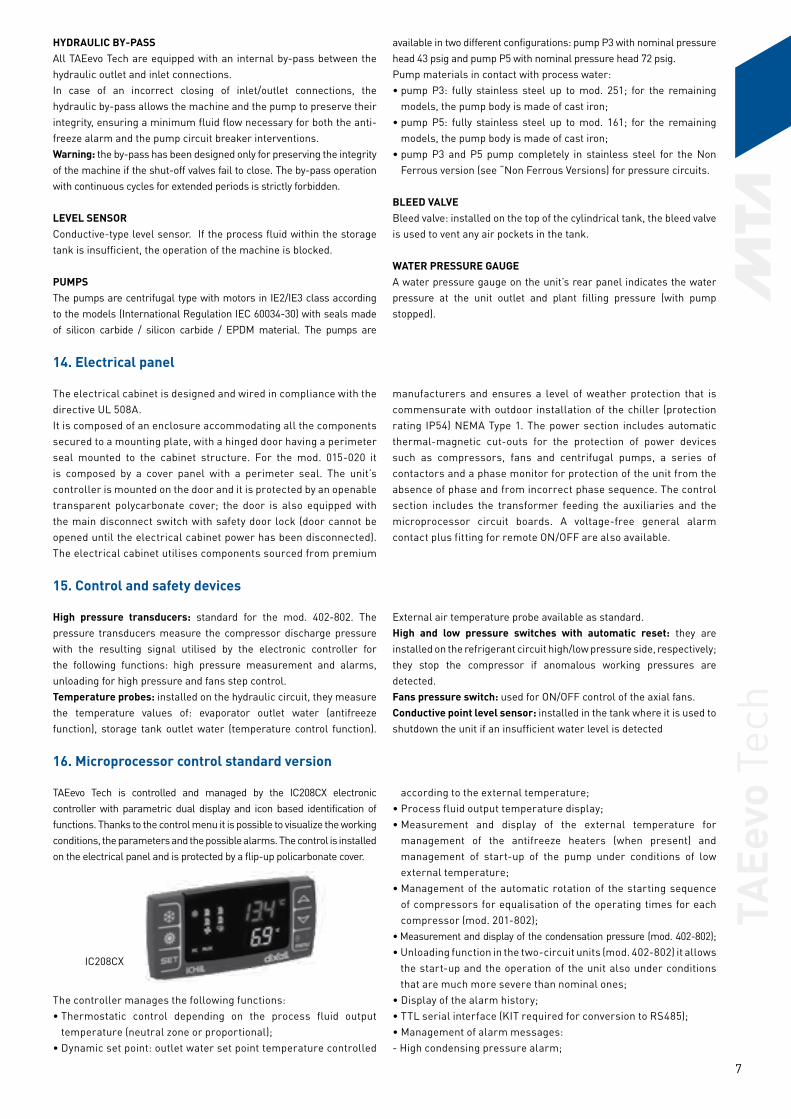
TAEevo Tech is controlled and managed by the IC208CX electronic controller with parametric dual display and icon based identification of functions. Thanks to the control menu it is possible to visualize the working conditions, the parameters and the possible alarms. The control is installed on the electrical panel and is protected by a flip-up policarbonate cover.
The controller manages the following functions:• Thermostatic control depending on the process fluid output
temperature (neutral zone or proportional);• Dynamic set point: outlet water set point temperature controlled
according to the external temperature;• Process fluid output temperature display;• Measurement and display of the external temperature for
management of the antifreeze heaters (when present) and management of start-up of the pump under conditions of low external temperature;
• Management of the automatic rotation of the starting sequence of compressors for equalisation of the operating times for each compressor (mod. 201-802);
• Measurement and display of the condensation pressure (mod. 402-802);• Unloading function in the two-circuit units (mod. 402-802) it allows
the start-up and the operation of the unit also under conditions that are much more severe than nominal ones;
• Display of the alarm history;• TTL serial interface (KIT required for conversion to RS485);• Management of alarm messages:- High condensing pressure alarm;
IC208CX
TAEe
vo T
ech
8
- low evaporation pressure alarm;- freeze alarm on water at evaporator outlet;- compressor fault alarm;- pump thermal protection alarm;- tank level alarm;
- count of operating hours of the unit and of the individual compressors.
A voltage-free contact is provided for remotisaton of a general alarm signal.
17. Options, kits and special designs17.1 Options
Options must be specified at the time of order because they can only be installed in the factory.
• VERSION WITHOUT PUMP: includes the provision for electronic power of an external pump equivalent to a P3.
• POWER SUPPLY 400V/3/50 Hz: see relative documentation.
• POWER SUPPLY 400V/3/50 Hz - 460V/3/60 Hz dual frequency: see relative documentation.
• PAINTED CONDENSING COIL: epoxy primer and polyurethane-base paint (GRAY) to the coils, collectors and bends.
17.2 Kits
The kits are supplied separately, generally at the same time of the unit, and installed by the user. They can be supplied later as spare parts,modification kits, completion kits, etc.:
• HYDRAULIC CIRCUIT MANUAL FILLING TANK KIT: the tank kit ensures filling of the tank and hydraulic circuit when the latter is not pressurised (open circuits). The kit is composed of:
- plastic tank for filling the circuit and displaying the water level; - galvanized and painted sheet steel supporting frame/casing; - connecting fittings with tank.The tank kit may be installed directly on the unit at the factory and is also available in “sales kit” version. For models 015-020 it is not possible to choose the kit from the configurator but it is only available in the “sales kit” version.
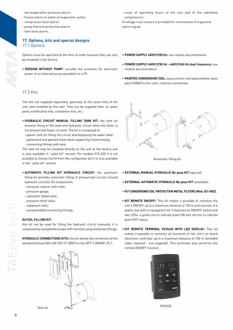
• AUTOMATIC FILLING KIT HYDRAULIC CIRCUIT: the automatic filling kit provides automatic filling of pressurised circuits (closed hydraulic circuits). Kit composition:
- pressure reducer with valve; - pressure gauge; - automatic bleed valve; - pressure relief valve; - expansion tank; - preassembled connecting fittings. GLYCOL FILLING KIT:this kit can be used for filling the hydraulic circuit manually, it is composed by a polyethilene pipe with hermetic plug and brass fittings. HYDRAULIC CONNECTIONS KITS: this kit allows the conversion of the standard thread GAS UNI ISO 7/1 (BSP) to the NPT F ANSIB1.20.1.
• EXTERNAL MANUAL HYDRAULIC By-pass KIT (special).
• EXTERNAL AUTOMATIC HYDRAULIC By-pass KIT (available).
• KIT CONDENSING COIL PROTECTION METAL FILTERS (Mod. 031-802).
• KIT REMOTE ON/OFF: This kit makes it possible to remotise the unit’s ON/OFF up to a maximum distance of 150 m and consists of a plastic box with a transparent lid. It features an ON/OFF switch and two LEDs, a green one to indicate plant ON and red one to indicate plant OFF status.
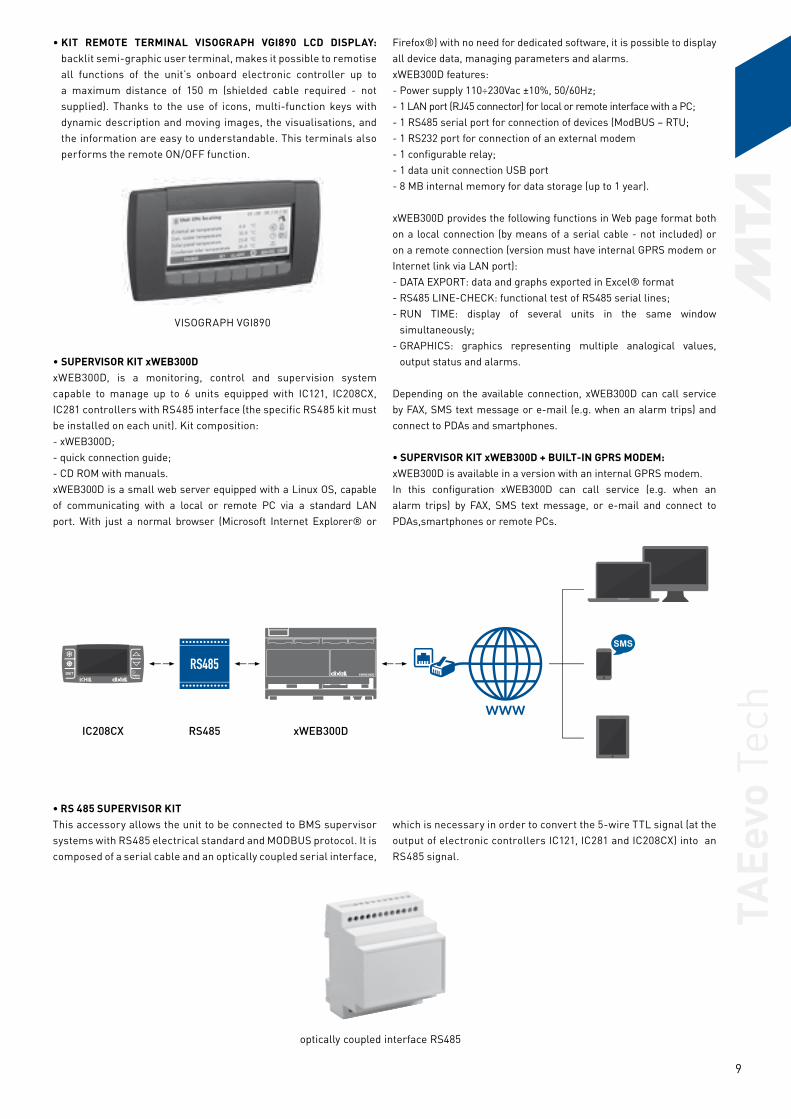
• KIT REMOTE TERMINAL VICX620 WITH LED DISPLAY: This kit makes it possible to remotise all functions of the unit’s on board electronic controller up to a maximum distance of 150 m (shielded cable required - not supplied). This terminals also performs the remote ON/OFF function.
VICX620Tank kit
Automatic filling kit
TAEe
vo T
ech
9
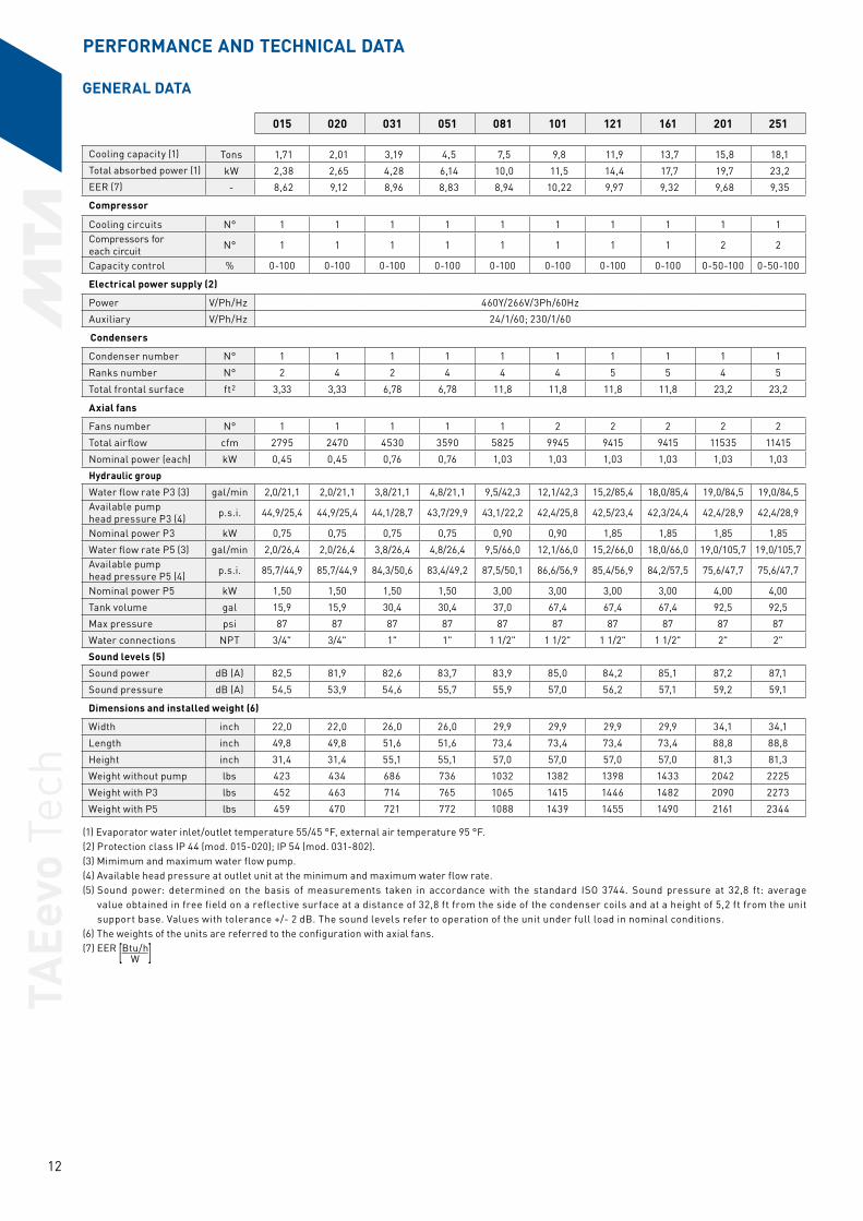
• KIT REMOTE TERMINAL VISOGRAPH VGI890 LCD DISPLAY: backlit semi-graphic user terminal, makes it possible to remotise all functions of the unit’s onboard electronic controller up to a maximum distance of 150 m (shielded cable required - not supplied). Thanks to the use of icons, multi-function keys with dynamic description and moving images, the visualisations, and the information are easy to understandable. This terminals also performs the remote ON/OFF function.
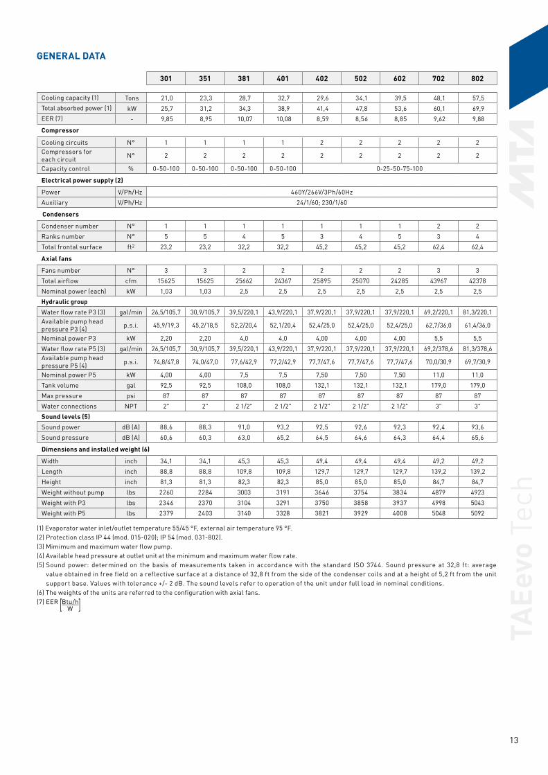
• SUPERVISOR KIT xWEB300DxWEB300D, is a monitoring, control and supervision system capable to manage up to 6 units equipped with IC121, IC208CX, IC281 controllers with RS485 interface (the specific RS485 kit must be installed on each unit). Kit composition:- xWEB300D;- quick connection guide;- CD ROM with manuals.xWEB300D is a small web server equipped with a Linux OS, capable of communicating with a local or remote PC via a standard LAN port. With just a normal browser (Microsoft Internet Explorer® or
Firefox®) with no need for dedicated software, it is possible to display all device data, managing parameters and alarms.xWEB300D features: - Power supply 110÷230Vac ±10%, 50/60Hz;- 1 LAN port (RJ45 connector) for local or remote interface with a PC;- 1 RS485 serial port for connection of devices (ModBUS – RTU;- 1 RS232 port for connection of an external modem- 1 configurable relay;- 1 data unit connection USB port- 8 MB internal memory for data storage (up to 1 year).
xWEB300D provides the following functions in Web page format both on a local connection (by means of a serial cable - not included) or on a remote connection (version must have internal GPRS modem or Internet link via LAN port):- DATA EXPORT: data and graphs exported in Excel® format- RS485 LINE-CHECK: functional test of RS485 serial lines;- RUN TIME: display of several units in the same window
simultaneously;- GRAPHICS: graphics representing multiple analogical values,
output status and alarms.
Depending on the available connection, xWEB300D can call service by FAX, SMS text message or e-mail (e.g. when an alarm trips) and connect to PDAs and smartphones.
• SUPERVISOR KIT xWEB300D + BUILT-IN GPRS MODEM:xWEB300D is available in a version with an internal GPRS modem. In this configuration xWEB300D can call service (e.g. when an alarm trips) by FAX, SMS text message, or e-mail and connect to PDAs,smartphones or remote PCs.
• RS 485 SUPERVISOR KITThis accessory allows the unit to be connected to BMS supervisor systems with RS485 electrical standard and MODBUS protocol. It is composed of a serial cable and an optically coupled serial interface,
which is necessary in order to convert the 5-wire TTL signal (at the output of electronic controllers IC121, IC281 and IC208CX) into an RS485 signal.
IC208CX RS485 xWEB300D
VISOGRAPH VGI890
optically coupled interface RS485

TAEe
vo T
ech
10
• GATEWAY TREND KITIt allows connection of the unit and its supervisor by a Trend control
network. This kit must necessary be combined with kit "RS485 Modbus supervisor kit".
17.3 Special designs
The special features are not described in detail in our catalogues. The feasibility of special designs must be assessed, confirmed, and priced on a case by case basis in agreement with our sales offices before placing the order.• Water flow switch: device to protects the evaporator from the
absence of water flow.• Copper-copper condensing coils: with copper tubes and fins and
brass shoulders.• FIN GUARD/BLYGOLD treatment for condensing coils: consisting
of a passivating primer and a polyurethane-based top coat.
• R407F version for outlet water temperature down to 14 °F.• R134a version for external air temperature up to +122 °F.• Centrifugal fans electronic control.• 400V/3/50 Hz (see dedicated documentations).• 400V/3/50 Hz - 460V/3/60 Hz dual frequency (mod. 015-161) (see
dedicated documentations).• Different power supply (230V/3/60 Hz; 575V/3/60 Hz) avaiable on
request.
18. Lifting
All units are positioned and secured to pallets, on which they can be handled by means of forklift trucks and pallet trucks. The units can also be moved even when not standing on a pallet thanks to features on the plinth (mod. 015-351).
The 201-802 models can be handled by inserting lifting bars into the plinth and utilising lifting straps. The bars for lifting and handling aren’tsupplied as standard.

TAEe
vo T
ech
11
SELECTION GUIDE
Selection of a chiller is performed by means of the tables given in the “Selection guide” and by means of the Data Tables relative to eachmodel. For correct selection of a chiller it is necessary:
1) Ensure that the operating limits specified in the “Working limits” table are complied with”.
2) Ensure that the flow rate of water to be cooled is between the flow values specified in the “General Data” table of each unit; excessively low flow rates will result in laminar flow and, consequently, a risk offreezing and poor temperature control; in contrast, excessively high flow rates lead to excessive load drops and possible bursting ofevaporator piping.
3) Add ethylene glycol or other antifreeze liquids when using the chiller at water outlet temperatures below +41 °F; consult the “Water and ethylene glycol solutions” table to find the quantity
of ethylene glycol required and to assess the reduction in cooling duty, the increase in compressor power input, and the increase in evaporator pressure drops due to the presence of ethylene glycol.
4) If TAEevo Tech models are installed at altitudes in excess of 1640 ft, assess the reduction of cooling performance and the increase in compressor power input values by means of the coefficients given in the”Condenser corrective coefficients” table.
5) If the temperature difference between the evaporator water inlet andoutlet differs by 10 °F, correct the cooling capacity and power input utilising the“ΔT corrective coefficients ≠ 10 °F” tables.
TAEe
vo T
ech
12
(1) Evaporator water inlet/outlet temperature 55/45 °F, external air temperature 95 °F.(2) Protection class IP 44 (mod. 015-020); IP 54 (mod. 031-802).(3) Mimimum and maximum water flow pump. (4) Available head pressure at outlet unit at the minimum and maximum water flow rate. (5) Sound power: determined on the basis of measurements taken in accordance with the standard ISO 3744. Sound pressure at 32,8 ft: average
value obtained in free field on a reflective surface at a distance of 32,8 ft from the side of the condenser coils and at a height of 5,2 ft from the unit support base. Values with tolerance +/- 2 dB. The sound levels refer to operation of the unit under full load in nominal conditions.
(6) The weights of the units are referred to the configuration with axial fans.(7) EER [Btu/h] W
015 020 031 051 081 101 121 161 201 251
Cooling capacity (1) Tons 1,71 2,01 3,19 4,5 7,5 9,8 11,9 13,7 15,8 18,1Total absorbed power (1) kW 2,38 2,65 4,28 6,14 10,0 11,5 14,4 17,7 19,7 23,2EER (7) - 8,62 9,12 8,96 8,83 8,94 10,22 9,97 9,32 9,68 9,35
Compressor
Cooling circuits N° 1 1 1 1 1 1 1 1 1 1Compressors for each circuit N° 1 1 1 1 1 1 1 1 2 2
Capacity control % 0-100 0-100 0-100 0-100 0-100 0-100 0-100 0-100 0-50-100 0-50-100
Electrical power supply (2)
Power V/Ph/Hz 460Y/266V/3Ph/60Hz
Auxiliary V/Ph/Hz 24/1/60; 230/1/60
Condensers
Condenser number N° 1 1 1 1 1 1 1 1 1 1
Ranks number N° 2 4 2 4 4 4 5 5 4 5
Total frontal surface ft2 3,33 3,33 6,78 6,78 11,8 11,8 11,8 11,8 23,2 23,2
Axial fans
Fans number N° 1 1 1 1 1 2 2 2 2 2
Total airflow cfm 2795 2470 4530 3590 5825 9945 9415 9415 11535 11415
Nominal power (each) kW 0,45 0,45 0,76 0,76 1,03 1,03 1,03 1,03 1,03 1,03
Hydraulic group
Water flow rate P3 (3) gal/min 2,0/21,1 2,0/21,1 3,8/21,1 4,8/21,1 9,5/42,3 12,1/42,3 15,2/85,4 18,0/85,4 19,0/84,5 19,0/84,5Available pump head pressure P3 (4) p.s.i. 44,9/25,4 44,9/25,4 44,1/28,7 43,7/29,9 43,1/22,2 42,4/25,8 42,5/23,4 42,3/24,4 42,4/28,9 42,4/28,9
Nominal power P3 kW 0,75 0,75 0,75 0,75 0,90 0,90 1,85 1,85 1,85 1,85
Water flow rate P5 (3) gal/min 2,0/26,4 2,0/26,4 3,8/26,4 4,8/26,4 9,5/66,0 12,1/66,0 15,2/66,0 18,0/66,0 19,0/105,7 19,0/105,7Available pump head pressure P5 (4) p.s.i. 85,7/44,9 85,7/44,9 84,3/50,6 83,4/49,2 87,5/50,1 86,6/56,9 85,4/56,9 84,2/57,5 75,6/47,7 75,6/47,7
Nominal power P5 kW 1,50 1,50 1,50 1,50 3,00 3,00 3,00 3,00 4,00 4,00
Tank volume gal 15,9 15,9 30,4 30,4 37,0 67,4 67,4 67,4 92,5 92,5
Max pressure psi 87 87 87 87 87 87 87 87 87 87
Water connections NPT 3/4" 3/4" 1" 1" 1 1/2" 1 1/2" 1 1/2" 1 1/2" 2" 2"
Sound levels (5)
Sound power dB (A) 82,5 81,9 82,6 83,7 83,9 85,0 84,2 85,1 87,2 87,1
Sound pressure dB (A) 54,5 53,9 54,6 55,7 55,9 57,0 56,2 57,1 59,2 59,1
Dimensions and installed weight (6)
Width inch 22,0 22,0 26,0 26,0 29,9 29,9 29,9 29,9 34,1 34,1
Length inch 49,8 49,8 51,6 51,6 73,4 73,4 73,4 73,4 88,8 88,8
Height inch 31,4 31,4 55,1 55,1 57,0 57,0 57,0 57,0 81,3 81,3
Weight without pump lbs 423 434 686 736 1032 1382 1398 1433 2042 2225
Weight with P3 lbs 452 463 714 765 1065 1415 1446 1482 2090 2273
Weight with P5 lbs 459 470 721 772 1088 1439 1455 1490 2161 2344
PERFORMANCE AND TECHNICAL DATA
GENERAL DATA
TAEe
vo T
ech
13
(1) Evaporator water inlet/outlet temperature 55/45 °F, external air temperature 95 °F.(2) Protection class IP 44 (mod. 015-020); IP 54 (mod. 031-802).(3) Mimimum and maximum water flow pump. (4) Available head pressure at outlet unit at the minimum and maximum water flow rate. (5) Sound power: determined on the basis of measurements taken in accordance with the standard ISO 3744. Sound pressure at 32,8 ft: average
value obtained in free field on a reflective surface at a distance of 32,8 ft from the side of the condenser coils and at a height of 5,2 ft from the unit support base. Values with tolerance +/- 2 dB. The sound levels refer to operation of the unit under full load in nominal conditions.
(6) The weights of the units are referred to the configuration with axial fans.(7) EER [Btu/h] W
301 351 381 401 402 502 602 702 802
Cooling capacity (1) Tons 21,0 23,3 28,7 32,7 29,6 34,1 39,5 48,1 57,5Total absorbed power (1) kW 25,7 31,2 34,3 38,9 41,4 47,8 53,6 60,1 69,9EER (7) - 9,85 8,95 10,07 10,08 8,59 8,56 8,85 9,62 9,88
Compressor
Cooling circuits N° 1 1 1 1 2 2 2 2 2Compressors for each circuit N° 2 2 2 2 2 2 2 2 2
Capacity control % 0-50-100 0-50-100 0-50-100 0-50-100 0-25-50-75-100
Electrical power supply (2)
Power V/Ph/Hz 460Y/266V/3Ph/60Hz
Auxiliary V/Ph/Hz 24/1/60; 230/1/60
Condensers
Condenser number N° 1 1 1 1 1 1 1 2 2
Ranks number N° 5 5 4 5 3 4 5 3 4
Total frontal surface ft2 23,2 23,2 32,2 32,2 45,2 45,2 45,2 62,4 62,4
Axial fans
Fans number N° 3 3 2 2 2 2 2 3 3
Total airflow cfm 15625 15625 25662 24367 25895 25070 24285 43967 42378
Nominal power (each) kW 1,03 1,03 2,5 2,5 2,5 2,5 2,5 2,5 2,5
Hydraulic group
Water flow rate P3 (3) gal/min 26,5/105,7 30,9/105,7 39,5/220,1 43,9/220,1 37,9/220,1 37,9/220,1 37,9/220,1 69,2/220,1 81,3/220,1Available pump head pressure P3 (4) p.s.i. 45,9/19,3 45,2/18,5 52,2/20,4 52,1/20,4 52,4/25,0 52,4/25,0 52,4/25,0 62,7/36,0 61,4/36,0
Nominal power P3 kW 2,20 2,20 4,0 4,0 4,00 4,00 4,00 5,5 5,5
Water flow rate P5 (3) gal/min 26,5/105,7 30,9/105,7 39,5/220,1 43,9/220,1 37,9/220,1 37,9/220,1 37,9/220,1 69,2/378,6 81,3/378,6Available pump head pressure P5 (4) p.s.i. 74,8/47,8 74,0/47,0 77,6/42,9 77,2/42,9 77,7/47,6 77,7/47,6 77,7/47,6 70,0/30,9 69,7/30,9
Nominal power P5 kW 4,00 4,00 7,5 7,5 7,50 7,50 7,50 11,0 11,0
Tank volume gal 92,5 92,5 108,0 108,0 132,1 132,1 132,1 179,0 179,0
Max pressure psi 87 87 87 87 87 87 87 87 87
Water connections NPT 2" 2" 2 1/2" 2 1/2" 2 1/2" 2 1/2" 2 1/2" 3" 3"
Sound levels (5)
Sound power dB (A) 88,6 88,3 91,0 93,2 92,5 92,6 92,3 92,4 93,6
Sound pressure dB (A) 60,6 60,3 63,0 65,2 64,5 64,6 64,3 64,4 65,6
Dimensions and installed weight (6)
Width inch 34,1 34,1 45,3 45,3 49,4 49,4 49,4 49,2 49,2
Length inch 88,8 88,8 109,8 109,8 129,7 129,7 129,7 139,2 139,2
Height inch 81,3 81,3 82,3 82,3 85,0 85,0 85,0 84,7 84,7
Weight without pump lbs 2260 2284 3003 3191 3646 3754 3834 4879 4923
Weight with P3 lbs 2346 2370 3104 3291 3750 3858 3937 4998 5043
Weight with P5 lbs 2379 2403 3140 3328 3821 3929 4008 5048 5092
GENERAL DATA

TAEe
vo T
ech
14
ModelPower supply With axial fans and pump P3 With axial fans and pump P5 With axial fans and SP
Hz FLI (kW) FLI (HP) FLA (A) ICF1 (A) FLI (kW) FLI (HP) FLA (A) ICF1 (A) FLI (kW) FLI (HP) FLA (A) ICF1 (A)015 460V/3Ph/60Hz 4,8 7-1/2 9,4 28 6,4 10 12 31 3,9 7-1/2 7,9 27
020 460V/3Ph/60Hz 4,9 7-1/2 9,4 32 6,6 10 12 35 4,1 7-1/2 7,9 31
031 460V/3Ph/60Hz 6,8 7-1/2 11 47 8,4 10 13 50 6,0 7-1/2 9,1 46
051 460V/3Ph/60Hz 8,8 10 13 63 10 15 15 66 7,9 7-1/2 11 62
081 460V/3Ph/60Hz 15 15 21 116 17 20 24 120 13 15 19 114
101 460V/3Ph/60Hz 18 20 26 127 20 25 29 131 16 20 24 125
121 460V/3Ph/60Hz 22 25 32 154 23 25 34 156 20 25 29 150
161 460V/3Ph/60Hz 25 30 38 177 26 30 40 179 23 30 35 173
201 460V/3Ph/60Hz 29 40 41 118 31 40 45 122 26 30 38 114
251 460V/3Ph/60Hz 32 40 47 129 35 40 51 133 30 40 44 125
301 460V/3Ph/60Hz 37 50 54 154 39 50 58 158 35 40 50 150
351 460V/3Ph/60Hz 44 60 66 177 46 60 69 181 41 50 62 173
381 460V/3Ph/60Hz 50 75 79 181 54 75 83 185 46 60 71 173
401 460V/3Ph/60Hz 57 75 85 233 61 75 89 237 52 60 77 225
402 460V/3Ph/60Hz 58 75 85 122 62 75 89 126 54 60 77 114
502 460V/3Ph/60Hz 66 100 97 133 70 100 101 137 61 75 89 125
602 460V/3Ph/60Hz 73 100 107 158 77 100 111 162 68 100 99 150
702 460V/3Ph/60Hz 85 100 123 160 89 125 129 165 78 100 114 150
802 460V/3Ph/60Hz 96 125 147 183 100 125 153 188 89 125 138 173
P3 = pump P3;P5 = pump P5;SP = without pump;FLI = max power absorbed in the working limits condition;FLA = max current absorbed in the working limits condition;ICF1 = Start-up current at the start of the last compressor in the working limits condition.
(1) To calculate a different distance of the sound pressure level, use the formula: dB(A)L=dB(A)32,8 ft+Kdb.
Sound power: determined on the basis of measurements taken in accordance with the standard ISO 3744. Sound pressure at 32,8 ft: average value obtained in free field on a reflective surface at a distance of 32,8 ft from the side of the condenser coils and at a height of 5,2 ft from the unit support base. Values with tolerance +/- 2 dB. The sound levels refer to operation of the unit under full load in nominal conditions.
DistanceKdB
(1) L (ft)
3,3 15
9,8 10
16,4 6
32,8 0
ELECTRICAL DATA
Octave bands (Hz)Power Pressure
Model Version63 125 250 500 1000 2000 4000 8000
Sound power level LW dB (A) Lw dB (A) Lp dB (A) 32,8 ft
015 axials fans 50,3 63,3 75,6 77,9 77,3 73,1 65,4 55,9 82,5 54,5
020 axials fans 49,7 62,7 75,0 77,3 76,7 72,5 64,8 55,3 81,9 53,9
031 axials fans 53,6 75,0 75,9 72,2 78,1 73,7 66,7 58,9 82,6 54,6
051 axials fans 54,7 76,1 77,0 73,3 79,2 74,8 67,8 60,0 83,7 55,7
081 axials fans 52,9 71,7 72,0 75,0 80,7 77,3 71,2 60,9 83,9 55,9
101 axials fans 53,8 72,7 73,1 76,1 81,8 78,4 72,3 61,9 85,0 57,0
121 axials fans 53,0 71,9 72,3 75,3 81,0 77,6 71,5 61,1 84,2 56,2
161 axials fans 53,6 72,7 73,1 76,1 81,8 78,4 72,2 61,7 85,1 57,1
201 axials fans 62,8 74,8 75,9 78,0 83,9 80,8 74,3 62,2 87,2 59,2
251 axials fans 62,7 74,7 75,8 77,9 83,8 80,7 74,2 62,1 87,1 59,1
301 axials fans 63,8 76,0 77,1 79,3 85,4 82,1 75,5 63,1 88,6 60,6
351 axials fans 63,5 75,7 76,8 79,0 85,1 81,8 75,2 62,8 88,3 60,3
381 axials fans 50,4 74,6 78,9 83,7 85,1 85,6 83,1 75,4 91,0 63,0
401 axials fans 51,8 74,6 79,0 86,8 87,9 87,0 85,4 75,1 93,2 65,2
402 axials fans 66,9 79,6 80,8 83,1 89,4 86,0 79,1 66,2 92,5 64,5
502 axials fans 67,0 79,7 80,9 83,2 89,5 86,1 79,2 66,3 92,6 64,6
602 axials fans 66,7 79,4 80,6 82,9 89,2 85,8 78,9 66,0 98,3 64,3
702 axials fans 53,8 76,5 80,7 85,6 85,9 86,6 85,0 77,4 92,4 64,4
802 axials fans 52,4 76,5 80,8 86,2 87,7 88,4 85,8 78,4 93,6 65,6
SOUND LEVELS
TAEe
vo T
ech
15
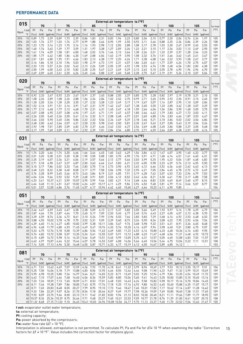
015 External air temperature ta (°F)ta max
(°F)70 75 85 90 95 100 105
Glycol t out Pf Pa Fw Pf Pa Fw Pf Pa Fw Pf Pa Fw Pf Pa Fw Pf Pa Fw Pf Pa Fw
°F (Ton) (kW) (gal/min) (Ton) (kW) (gal/min) (Ton) (kW) (gal/min) (Ton) (kW) (gal/min) (Ton) (kW) (gal/min) (Ton) (kW) (gal/min) (Ton) (kW) (gal/min)35% 15 0,89 1,73 2,39 0,89 1,73 2,39 0,86 1,83 2,31 0,83 1,94 2,23 0,80 2,06 2,15 0,77 2,20 2,06 0,74 2,34 1,97 10535% 20 1,03 1,74 2,77 1,03 1,74 2,77 0,99 1,88 2,64 0,95 1,99 2,55 0,92 2,11 2,46 0,88 2,25 2,36 0,84 2,39 2,26 10825% 25 1,23 1,75 3,16 1,23 1,75 3,16 1,16 1,93 2,98 1,12 2,05 2,88 1,08 2,17 2,78 1,03 2,30 2,67 0,99 2,45 2,55 10925% 30 1,40 1,74 3,62 1,39 1,77 3,59 1,31 1,97 3,38 1,27 2,09 3,26 1,22 2,21 3,15 1,17 2,34 3,03 1,12 2,49 2,90 10920% 35 1,61 1,74 4,09 1,58 1,81 4,00 1,48 2,02 3,76 1,44 2,13 3,64 1,38 2,26 3,51 1,33 2,39 3,37 1,28 2,54 3,23 10920% 40 1,85 1,77 4,42 1,80 1,86 4,30 1,69 2,08 4,04 1,63 2,19 3,90 1,58 2,32 3,76 1,51 2,46 3,62 1,45 2,61 3,47 109
45 2,01 1,81 4,80 1,95 1,91 4,66 1,83 2,13 4,38 1,77 2,25 4,24 1,71 2,38 4,08 1,64 2,52 3,93 1,58 2,67 3,77 10950 2,16 1,86 5,18 2,10 1,96 5,03 1,98 2,19 4,73 1,91 2,31 4,57 1,84 2,45 4,41 1,77 2,59 4,24 1,70 2,75 4,07 10955 2,33 1,92 5,57 2,26 2,02 5,42 2,13 2,26 5,09 2,05 2,39 4,92 1,98 2,53 4,74 1,90 2,68 4,56 1,83 2,83 4,38 10960 2,50 1,99 6,00 2,43 2,10 5,82 2,28 2,35 5,47 2,21 2,49 5,29 2,13 2,63 5,10 2,05 2,78 4,90 1,96 2,94 4,70 10965 2,69 2,09 6,45 2,61 2,20 6,26 2,45 2,46 5,88 2,37 2,60 5,68 2,28 2,75 5,47 2,19 2,91 5,26 2,10 3,07 5,04 105
t out: evaporator outlet water temperature; ta: external air temperature; Pf: cooling capacity; Pa: power absorbed by the compressors; Fw: water flow rate (∆T = 10 °F). Interpolation is allowed, extrapolation is not permitted. To calculate Pf, Pa and Fw for ∆T≠ 10 °F when examining the table ”Correction factors for ∆T ≠ 10 °F”. Value includes the correction factor for ethylene glycol.
020 External air temperature ta (°F)ta max
(°F)70 75 85 90 95 100 105
Glycol t out Pf Pa Fw Pf Pa Fw Pf Pa Fw Pf Pa Fw Pf Pa Fw Pf Pa Fw Pf Pa Fw
°F (Ton) (kW) (gal/min) (Ton) (kW) (gal/min) (Ton) (kW) (gal/min) (Ton) (kW) (gal/min) (Ton) (kW) (gal/min) (Ton) (kW) (gal/min) (Ton) (kW) (gal/min)35% 15 0,92 2,33 2,47 0,92 2,33 2,47 0,91 2,37 2,45 0,88 2,55 2,37 0,85 2,75 2,28 0,82 2,97 2,19 0,78 3,21 2,10 10535% 20 1,08 2,26 2,89 1,08 2,26 2,88 1,06 2,34 2,84 1,02 2,52 2,75 0,99 2,71 2,65 0,95 2,92 2,55 0,91 3,15 2,45 10925% 25 1,30 2,20 3,36 1,30 2,20 3,35 1,27 2,32 3,28 1,23 2,49 3,17 1,19 2,67 3,07 1,14 2,87 2,95 1,10 3,09 2,84 10925% 30 1,52 2,16 3,91 1,51 2,16 3,91 1,47 2,31 3,79 1,42 2,47 3,67 1,38 2,65 3,55 1,33 2,85 3,42 1,28 3,07 3,29 10920% 35 1,77 2,12 4,48 1,77 2,12 4,48 1,70 2,31 4,31 1,65 2,47 4,18 1,59 2,64 4,04 1,54 2,84 3,90 1,48 3,05 3,75 10920% 40 2,07 2,08 4,95 2,07 2,08 4,94 1,97 2,31 4,71 1,91 2,47 4,57 1,85 2,64 4,42 1,79 2,83 4,27 1,72 3,03 4,11 109
45 2,26 2,05 5,40 2,26 2,05 5,41 2,14 2,32 5,11 2,08 2,48 4,97 2,01 2,65 4,80 1,94 2,83 4,64 1,87 3,03 4,47 10950 2,46 2,03 5,90 2,45 2,06 5,86 2,32 2,33 5,54 2,24 2,49 5,37 2,18 2,66 5,21 2,10 2,84 5,02 2,02 3,04 4,84 10955 2,68 2,00 6,42 2,64 2,07 6,31 2,50 2,35 5,98 2,43 2,50 5,81 2,35 2,67 5,62 2,27 2,85 5,43 2,19 3,04 5,24 10960 2,92 1,98 7,01 2,85 2,09 6,82 2,70 2,37 6,46 2,62 2,52 6,27 2,54 2,69 6,08 2,45 2,86 5,88 2,37 3,05 5,68 10865 3,17 1,99 7,60 3,09 2,11 7,41 2,92 2,39 7,01 2,84 2,54 6,80 2,75 2,71 6,59 2,66 2,89 6,38 2,57 3,08 6,16 105
031 External air temperature ta (°F)ta max
(°F)70 75 85 90 95 100 105
Glycol t out Pf Pa Fw Pf Pa Fw Pf Pa Fw Pf Pa Fw Pf Pa Fw Pf Pa Fw Pf Pa Fw
°F (Ton) (kW) (gal/min) (Ton) (kW) (gal/min) (Ton) (kW) (gal/min) (Ton) (kW) (gal/min) (Ton) (kW) (gal/min) (Ton) (kW) (gal/min) (Ton) (kW) (gal/min)35% 15 1,74 3,20 4,66 1,74 3,20 4,66 1,66 3,44 4,45 1,60 3,63 4,29 1,54 3,84 4,12 1,47 4,07 3,95 1,40 4,33 3,77 10535% 20 2,01 3,20 5,38 2,01 3,20 5,38 1,90 3,50 5,08 1,83 3,70 4,90 1,76 3,91 4,71 1,68 4,14 4,51 1,61 4,40 4,31 10925% 25 2,35 3,19 6,07 2,34 3,21 6,04 2,19 3,57 5,66 2,12 3,77 5,46 2,03 3,99 5,25 1,95 4,22 5,04 1,87 4,48 4,82 10925% 30 2,71 3,18 6,98 2,67 3,27 6,87 2,50 3,63 6,44 2,41 3,83 6,21 2,32 4,05 5,98 2,23 4,29 5,74 2,13 4,55 5,50 10920% 35 3,10 3,17 7,86 3,02 3,33 7,64 2,83 3,70 7,16 2,73 3,90 6,92 2,63 4,12 6,66 2,52 4,36 6,40 2,42 4,63 6,13 10920% 40 3,48 3,23 8,32 3,38 3,40 8,08 3,17 3,77 7,58 3,06 3,98 7,32 2,95 4,21 7,05 2,84 4,45 6,78 2,72 4,72 6,49 109
45 3,76 3,28 8,99 3,65 3,46 8,73 3,43 3,84 8,19 3,31 4,05 7,91 3,19 4,28 7,62 3,07 4,53 7,33 2,94 4,79 7,03 10950 4,04 3,34 9,66 3,92 3,52 9,39 3,68 3,91 8,81 3,56 4,12 8,52 3,43 4,36 8,21 3,30 4,61 7,90 3,17 4,88 7,58 10955 4,33 3,41 10,37 4,21 3,59 10,07 3,95 3,99 9,46 3,82 4,21 9,14 3,68 4,44 8,82 3,55 4,69 8,49 3,40 4,97 8,15 10960 4,64 3,48 11,13 4,51 3,67 10,82 4,24 4,07 10,17 4,11 4,29 9,84 3,96 4,53 9,48 3,81 4,79 9,14 3,66 5,07 8,77 10865 5,01 3,57 12,00 4,86 3,76 11,65 4,57 4,17 10,96 4,42 4,40 10,60 4,27 4,64 10,23 4,11 4,90 9,85 - - - 104
051 External air temperature ta (°F)ta max
(°F)70 75 85 90 95 100 105
Glycol t out Pf Pa Fw Pf Pa Fw Pf Pa Fw Pf Pa Fw Pf Pa Fw Pf Pa Fw Pf Pa Fw
°F (Ton) (kW) (gal/min) (Ton) (kW) (gal/min) (Ton) (kW) (gal/min) (Ton) (kW) (gal/min) (Ton) (kW) (gal/min) (Ton) (kW) (gal/min) (Ton) (kW) (gal/min)35% 15 2,46 4,67 6,59 2,45 4,67 6,58 2,28 5,09 6,13 2,17 5,37 5,82 2,05 5,66 5,49 1,92 5,97 5,14 1,78 6,29 4,79 10635% 20 2,87 4,64 7,70 2,87 4,64 7,70 2,65 5,17 7,09 2,53 5,45 6,77 2,40 5,74 6,43 2,27 6,05 6,07 2,13 6,38 5,70 10925% 25 3,39 4,59 8,74 3,34 4,72 8,61 3,10 5,24 7,99 2,96 5,53 7,64 2,83 5,83 7,29 2,68 6,14 6,92 2,53 6,48 6,53 10925% 30 3,88 4,55 10,02 3,78 4,78 9,75 3,52 5,31 9,09 3,39 5,60 8,73 3,24 5,90 8,34 3,08 6,22 7,95 2,92 6,56 7,54 10920% 35 4,39 4,60 11,14 4,27 4,85 10,82 3,99 5,38 10,11 3,84 5,67 9,74 3,68 5,98 9,32 3,51 6,31 8,91 3,34 6,65 8,48 10920% 40 4,94 4,68 11,79 4,80 4,93 11,45 4,49 5,47 10,74 4,33 5,76 10,35 4,16 6,07 9,94 3,98 6,40 9,51 3,80 6,75 9,07 109
45 5,33 4,75 12,74 5,18 5,00 12,39 4,86 5,54 11,63 4,69 5,83 11,22 4,52 6,14 10,80 4,33 6,48 10,36 4,14 6,83 9,90 10950 5,74 4,82 13,72 5,58 5,07 13,35 5,24 5,61 12,55 5,07 5,91 12,12 4,88 6,23 11,67 4,68 6,56 11,21 4,48 6,92 10,73 10955 6,15 4,89 14,72 5,98 5,14 14,33 5,64 5,69 13,51 5,45 5,99 13,05 5,25 6,31 12,57 5,05 6,65 12,08 4,83 7,02 11,57 10960 6,62 4,97 15,87 6,44 5,22 15,44 6,07 5,78 14,53 5,87 6,08 14,06 5,66 6,40 13,56 5,44 6,75 13,04 5,22 7,11 12,51 10865 7,14 5,05 17,13 6,96 5,30 16,68 6,55 5,87 15,71 6,33 6,17 15,19 6,12 6,50 14,67 5,89 6,85 14,12 - - - 103
081 External air temperature ta (°F)ta max
(°F)70 75 85 90 95 100 105
Glycol t out Pf Pa Fw Pf Pa Fw Pf Pa Fw Pf Pa Fw Pf Pa Fw Pf Pa Fw Pf Pa Fw
°F (Ton) (kW) (gal/min) (Ton) (kW) (gal/min) (Ton) (kW) (gal/min) (Ton) (kW) (gal/min) (Ton) (kW) (gal/min) (Ton) (kW) (gal/min) (Ton) (kW) (gal/min)35% 15 4,71 7,01 12,62 4,69 7,07 12,59 4,36 7,92 11,70 4,18 8,41 11,22 3,99 8,94 10,69 3,77 9,53 10,12 3,55 10,17 9,51 10635% 20 5,25 7,00 14,06 5,18 7,19 13,88 4,83 8,06 12,95 4,64 8,55 12,44 4,44 9,08 11,90 4,22 9,67 11,32 3,99 10,31 10,69 10925% 25 5,95 6,98 15,35 5,80 7,34 14,97 5,44 8,21 14,03 5,23 8,71 13,49 5,02 9,25 12,94 4,79 9,84 12,35 4,54 10,49 11,72 10925% 30 6,62 7,10 17,07 6,44 7,48 16,60 6,04 8,36 15,59 5,83 8,85 15,04 5,60 9,41 14,43 5,35 10,00 13,80 5,10 10,65 13,14 10920% 35 7,33 7,26 18,59 7,13 7,65 18,09 6,71 8,53 17,01 6,48 9,03 16,43 6,24 9,58 15,82 5,98 10,17 15,16 5,70 10,84 14,45 10920% 40 8,11 7,46 19,38 7,89 7,86 18,85 7,43 8,75 17,74 7,18 9,25 17,16 6,92 9,80 16,53 6,65 10,40 15,88 6,35 11,07 15,17 109
45 8,71 7,65 20,83 8,48 8,05 20,27 7,99 8,95 19,10 7,73 9,46 18,47 7,45 10,01 17,82 7,17 10,62 17,14 6,87 11,28 16,42 10950 9,32 7,86 22,29 9,07 8,26 21,70 8,54 9,18 20,44 8,27 9,69 19,77 7,98 10,26 19,09 7,69 10,85 18,40 7,38 11,51 17,65 10955 9,92 8,09 23,75 9,66 8,50 23,13 9,11 9,42 21,82 8,82 9,94 21,12 8,52 10,50 20,40 8,21 11,11 19,66 7,89 11,77 18,90 10960 10,57 8,34 25,34 10,29 8,75 24,66 9,71 9,68 23,27 9,40 10,21 22,53 9,09 10,77 21,78 8,76 11,39 21,00 8,41 12,07 20,15 10865 11,32 8,68 27,15 11,02 9,10 26,43 10,41 10,03 24,96 10,08 10,56 24,17 9,75 11,13 23,37 9,40 11,75 22,53 9,04 12,43 21,67 105
PERFORMANCE DATA

TAEe
vo T
ech
16
101 External air temperature ta (°F)ta max
(°F)70 75 85 90 95 100 105
Glycol t out Pf Pa Fw Pf Pa Fw Pf Pa Fw Pf Pa Fw Pf Pa Fw Pf Pa Fw Pf Pa Fw
°F (Ton) (kW) (gal/min) (Ton) (kW) (gal/min) (Ton) (kW) (gal/min) (Ton) (kW) (gal/min) (Ton) (kW) (gal/min) (Ton) (kW) (gal/min) (Ton) (kW) (gal/min)35% 15 5,66 8,72 15,17 5,65 8,72 15,16 5,39 9,38 14,46 5,18 9,92 13,89 4,97 10,48 13,34 4,75 11,10 12,74 4,52 11,78 12,12 10935% 20 6,33 8,71 16,95 6,32 8,71 16,94 5,98 9,51 16,03 5,76 10,05 15,42 5,52 10,64 14,80 5,30 11,25 14,20 5,05 11,93 13,54 10925% 25 7,29 8,69 18,81 7,30 8,69 18,84 6,83 9,68 17,62 6,58 10,22 16,98 6,33 10,81 16,32 6,06 11,45 15,64 5,79 12,13 14,93 10925% 30 8,30 8,68 21,39 8,23 8,82 21,24 7,72 9,82 19,90 7,44 10,38 19,20 7,17 10,97 18,48 6,87 11,61 17,73 6,57 12,30 16,95 10920% 35 9,44 8,67 23,94 9,28 8,98 23,52 8,72 9,98 22,11 8,43 10,53 21,36 8,11 11,14 20,55 7,79 11,79 19,74 7,45 12,48 18,89 10920% 40 10,70 8,73 25,55 10,41 9,18 24,88 9,81 10,19 23,42 9,47 10,76 22,61 9,13 11,37 21,80 8,77 12,01 20,96 8,41 12,71 20,08 109
45 11,47 8,90 27,42 11,18 9,36 26,72 10,53 10,37 25,18 10,19 10,93 24,37 9,84 11,54 23,52 9,45 12,20 22,60 9,07 12,90 21,67 10950 12,23 9,08 29,27 11,92 9,54 28,52 11,27 10,55 26,95 10,91 11,12 26,10 10,53 11,73 25,19 10,14 12,38 24,26 9,74 13,09 23,30 10955 13,01 9,26 31,14 12,69 9,73 30,37 11,98 10,75 28,69 11,59 11,32 27,75 11,22 11,93 26,87 10,81 12,59 25,87 10,38 13,31 24,85 10860 13,83 9,46 33,14 13,49 9,92 32,33 12,75 10,95 30,56 12,36 11,53 29,63 11,94 12,15 28,62 11,51 12,82 27,59 11,07 13,52 26,52 10765 14,87 9,73 35,67 14,52 10,19 34,81 13,73 11,23 32,93 13,32 11,80 31,94 12,88 12,42 30,89 12,42 13,09 29,79 - - - 103
t out: evaporator outlet water temperature; ta: external air temperature; Pf: cooling capacity; Pa: power absorbed by the compressors; Fw: water flow rate (∆T = 10 °F). Interpolation is allowed, extrapolation is not permitted. To calculate Pf, Pa and Fw for ∆T≠ 10 °F when examining the table ”Correction factors for ∆T ≠ 10 °F”. Value includes the correction factor for ethylene glycol.
121 External air temperature ta (°F)ta max
(°F)70 75 85 90 95 100 105
Glycol t out Pf Pa Fw Pf Pa Fw Pf Pa Fw Pf Pa Fw Pf Pa Fw Pf Pa Fw Pf Pa Fw
°F (Ton) (kW) (gal/min) (Ton) (kW) (gal/min) (Ton) (kW) (gal/min) (Ton) (kW) (gal/min) (Ton) (kW) (gal/min) (Ton) (kW) (gal/min) (Ton) (kW) (gal/min)35% 15 6,98 10,48 18,72 6,97 10,48 18,70 6,67 11,37 17,89 6,44 11,98 17,28 6,19 12,64 16,60 5,94 13,33 15,93 5,67 14,06 15,22 10935% 20 7,75 10,51 20,76 7,74 10,51 20,75 7,35 11,58 19,69 7,09 12,22 19,00 6,83 12,89 18,31 6,56 13,60 17,56 6,27 14,35 16,79 10925% 25 8,90 10,54 22,96 8,86 10,67 22,86 8,36 11,85 21,57 8,07 12,50 20,82 7,78 13,19 20,06 7,47 13,92 19,26 7,14 14,70 18,43 10925% 30 10,09 10,56 26,03 9,96 10,88 25,68 9,40 12,07 24,24 9,09 12,73 23,45 8,75 13,44 22,57 8,40 14,19 21,67 8,04 14,98 20,75 10920% 35 11,47 10,59 29,08 11,21 11,12 28,42 10,58 12,32 26,82 10,23 12,99 25,94 9,87 13,70 25,03 9,49 14,46 24,05 9,07 15,29 22,99 10920% 40 12,93 10,88 30,88 12,61 11,43 30,11 11,89 12,65 28,41 11,50 13,33 27,48 11,10 14,05 26,50 10,66 14,82 25,47 10,20 15,66 24,36 109
45 13,84 11,12 33,09 13,51 11,68 32,29 12,73 12,92 30,43 12,33 13,60 29,47 11,89 14,33 28,43 11,43 15,11 27,34 10,96 15,94 26,20 10950 14,77 11,39 35,34 14,40 11,94 34,44 13,59 13,18 32,51 13,14 13,87 31,44 12,68 14,61 30,35 12,19 15,39 29,16 11,69 16,25 27,96 10955 15,71 11,64 37,63 15,32 12,19 36,68 14,45 13,43 34,60 13,98 14,13 33,48 13,49 14,88 32,31 12,98 15,68 31,08 12,45 16,53 29,80 10960 16,67 11,93 39,95 16,24 12,48 38,91 15,32 13,74 36,72 14,84 14,44 35,56 14,31 15,20 34,29 13,77 16,00 33,01 13,23 16,84 31,71 10965 17,94 12,32 43,01 17,47 12,87 41,90 16,48 14,13 39,52 15,95 14,84 38,25 15,39 15,60 36,91 14,82 16,41 35,53 14,21 17,28 34,08 105
161 External air temperature ta (°F)ta max
(°F)70 75 85 90 95 100 105
Glycol t out Pf Pa Fw Pf Pa Fw Pf Pa Fw Pf Pa Fw Pf Pa Fw Pf Pa Fw Pf Pa Fw
°F (Ton) (kW) (gal/min) (Ton) (kW) (gal/min) (Ton) (kW) (gal/min) (Ton) (kW) (gal/min) (Ton) (kW) (gal/min) (Ton) (kW) (gal/min) (Ton) (kW) (gal/min)35% 15 8,52 12,15 22,85 8,43 12,41 22,62 7,92 13,69 21,24 7,64 14,44 20,49 7,35 15,26 19,71 7,04 16,18 18,89 6,72 17,19 18,03 10935% 20 9,46 12,25 25,35 9,27 12,72 24,84 8,72 14,02 23,35 8,42 14,76 22,57 8,11 15,57 21,73 7,78 16,47 20,85 7,44 17,47 19,94 10925% 25 10,74 12,53 27,70 10,46 13,11 26,98 9,84 14,42 25,39 9,51 15,16 24,54 9,17 15,97 23,65 8,81 16,86 22,73 8,43 17,84 21,75 10925% 30 12,00 12,86 30,95 11,69 13,46 30,14 11,01 14,79 28,40 10,65 15,53 27,46 10,27 16,34 26,49 9,88 17,22 25,47 9,46 18,18 24,40 10920% 35 13,43 13,22 34,05 13,06 13,85 33,12 12,31 15,20 31,22 11,92 15,95 30,21 11,49 16,76 29,14 11,06 17,64 28,03 10,60 18,59 26,89 10920% 40 14,97 13,68 35,75 14,55 14,33 34,76 13,72 15,71 32,77 13,27 16,47 31,71 12,81 17,28 30,59 12,32 18,16 29,43 11,82 19,10 28,24 109
45 15,99 14,06 38,23 15,57 14,72 37,21 14,70 16,12 35,13 14,22 16,89 34,00 13,73 17,70 32,83 13,22 18,58 31,61 12,69 19,52 30,34 10950 17,05 14,43 40,80 16,58 15,12 39,67 15,64 16,56 37,42 15,14 17,33 36,23 14,64 18,15 35,02 14,09 19,03 33,71 13,52 19,98 32,34 10955 18,08 14,81 43,30 17,63 15,50 42,21 16,62 16,97 39,79 16,09 17,76 38,52 15,53 18,60 37,19 14,97 19,49 35,83 14,38 20,43 34,42 10960 19,17 15,22 45,94 18,67 15,94 44,73 17,60 17,44 42,18 17,04 18,25 40,82 16,46 19,09 39,44 15,86 19,99 38,00 15,24 20,93 36,51 10965 20,57 15,72 49,32 20,00 16,48 47,95 18,84 18,03 45,19 18,26 18,83 43,80 17,62 19,71 42,25 16,98 20,61 40,71 16,32 21,56 39,14 105
201 External air temperature ta (°F)ta max
(°F)70 75 85 90 95 100 105
Glycol t out Pf Pa Fw Pf Pa Fw Pf Pa Fw Pf Pa Fw Pf Pa Fw Pf Pa Fw Pf Pa Fw
°F (Ton) (kW) (gal/min) (Ton) (kW) (gal/min) (Ton) (kW) (gal/min) (Ton) (kW) (gal/min) (Ton) (kW) (gal/min) (Ton) (kW) (gal/min) (Ton) (kW) (gal/min)35% 15 9,25 14,03 24,80 9,24 14,03 24,78 8,66 15,64 23,23 8,31 16,60 22,29 7,93 17,65 21,27 7,52 18,81 20,16 7,07 20,07 18,97 10635% 20 10,34 14,00 27,71 10,30 14,17 27,59 9,62 15,89 25,79 9,26 16,85 24,81 8,87 17,91 23,75 8,44 19,07 22,61 7,98 20,35 21,39 10925% 25 11,92 13,97 30,75 11,72 14,48 30,22 11,00 16,19 28,37 10,60 17,17 27,35 10,18 18,23 26,25 9,73 19,40 25,09 9,24 20,67 23,84 10925% 30 13,57 13,96 35,00 13,22 14,73 34,09 12,44 16,45 32,08 11,99 17,45 30,92 11,54 18,52 29,76 11,05 19,69 28,51 10,54 20,98 27,18 10920% 35 15,29 14,27 38,76 14,89 15,04 37,75 14,03 16,78 35,57 13,58 17,76 34,42 13,08 18,84 33,16 12,54 20,04 31,79 11,99 21,33 30,39 10920% 40 17,16 14,67 40,99 16,72 15,45 39,93 15,77 17,21 37,66 15,26 18,20 36,44 14,72 19,28 35,17 14,16 20,46 33,82 13,54 21,78 32,35 109
45 18,40 15,03 43,99 17,92 15,83 42,85 16,94 17,59 40,50 16,41 18,58 39,23 15,85 19,67 37,89 15,26 20,86 36,48 14,64 22,16 35,01 10950 19,68 15,41 47,09 19,18 16,21 45,90 18,09 17,96 43,27 17,55 19,00 41,99 16,96 20,10 40,58 16,35 21,30 39,11 15,69 22,62 37,53 10955 20,98 15,80 50,23 20,44 16,61 48,94 19,31 18,43 46,23 18,70 19,46 44,77 18,08 20,57 43,29 17,44 21,77 41,76 16,78 23,08 40,17 10960 22,30 16,28 53,42 21,75 17,08 52,13 20,56 18,91 49,27 19,93 19,94 47,76 19,29 21,06 46,22 18,61 22,27 44,60 17,91 23,59 42,92 10865 23,91 16,90 57,34 23,31 17,73 55,91 22,04 19,58 52,85 21,37 20,62 51,24 20,71 21,72 49,66 19,99 22,95 47,95 19,26 24,28 46,18 105
251 External air temperature ta (°F)ta max
(°F)70 75 85 90 95 100 105
Glycol t out Pf Pa Fw Pf Pa Fw Pf Pa Fw Pf Pa Fw Pf Pa Fw Pf Pa Fw Pf Pa Fw
°F (Ton) (kW) (gal/min) (Ton) (kW) (gal/min) (Ton) (kW) (gal/min) (Ton) (kW) (gal/min) (Ton) (kW) (gal/min) (Ton) (kW) (gal/min) (Ton) (kW) (gal/min)35% 15 10,83 15,91 29,06 10,80 16,04 28,96 10,01 18,09 26,85 9,60 19,23 25,75 9,18 20,46 24,63 8,75 21,80 23,48 - - - 10435% 20 12,11 15,88 32,46 11,93 16,36 31,97 11,10 18,43 29,75 10,67 19,59 28,58 10,22 20,84 27,38 9,75 22,19 26,13 9,28 23,65 24,87 10625% 25 13,98 15,85 36,06 13,58 16,75 35,03 12,67 18,86 32,69 12,19 20,04 31,45 11,69 21,31 30,16 11,17 22,67 28,82 10,64 24,15 27,45 10925% 30 15,77 16,13 40,67 15,31 17,09 39,47 14,29 19,24 36,85 13,76 20,43 35,49 13,21 21,71 34,08 12,64 23,09 32,60 12,06 24,58 31,10 10920% 35 17,71 16,53 44,90 17,18 17,52 43,56 16,13 19,66 40,89 15,55 20,86 39,43 14,95 22,15 37,90 14,30 23,57 36,25 13,65 25,07 34,60 10920% 40 19,86 17,04 47,43 19,29 18,03 46,07 18,11 20,21 43,26 17,47 21,42 41,73 16,81 22,73 40,16 16,12 24,13 38,51 15,40 25,65 36,79 109
45 21,28 17,46 50,88 20,70 18,46 49,49 19,39 20,64 46,35 18,78 21,88 44,90 18,06 23,21 43,18 17,32 24,65 41,40 16,54 26,19 39,55 10950 22,76 17,87 54,46 22,14 18,88 52,98 20,81 21,12 49,78 20,10 22,37 48,08 19,34 23,71 46,28 18,55 25,17 44,38 17,75 26,70 42,47 10955 24,19 18,34 57,92 23,53 19,36 56,34 22,13 21,63 52,99 21,39 22,88 51,21 20,64 24,20 49,43 19,80 25,68 47,41 18,99 27,20 45,46 10960 25,72 18,83 61,64 25,02 19,88 59,94 23,54 22,17 56,41 22,75 23,44 54,53 21,94 24,79 52,58 21,09 26,26 50,53 20,21 27,81 48,43 10965 27,60 19,47 66,18 26,88 20,51 64,46 25,31 22,82 60,69 24,47 24,11 58,68 23,60 25,48 56,60 22,70 26,95 54,43 21,75 28,53 52,16 107
TAEe
vo T
ech
17
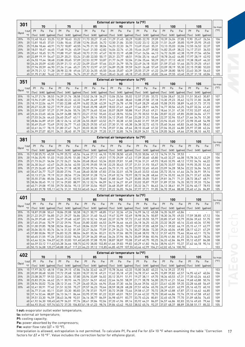
301 External air temperature ta (°F)ta max
(°F)70 75 85 90 95 100 105
Glycol t out Pf Pa Fw Pf Pa Fw Pf Pa Fw Pf Pa Fw Pf Pa Fw Pf Pa Fw Pf Pa Fw
°F (Ton) (kW) (gal/min) (Ton) (kW) (gal/min) (Ton) (kW) (gal/min) (Ton) (kW) (gal/min) (Ton) (kW) (gal/min) (Ton) (kW) (gal/min) (Ton) (kW) (gal/min)35% 15 12,40 18,43 33,25 12,39 18,43 33,22 11,73 20,27 31,45 11,29 21,45 30,29 10,85 22,70 29,09 10,39 24,04 27,85 9,90 25,47 26,54 10635% 20 13,81 18,45 37,01 13,84 18,46 37,08 12,96 20,65 34,72 12,50 21,84 33,50 12,02 23,12 32,20 11,51 24,49 30,85 10,99 25,95 29,45 10925% 25 15,86 18,46 40,91 15,72 18,87 40,55 14,75 21,10 38,04 14,23 22,33 36,71 13,69 23,63 35,31 13,13 25,03 33,86 12,55 26,52 32,37 10925% 30 18,01 18,47 46,45 17,68 19,24 45,59 16,61 21,50 42,82 16,04 22,74 41,35 15,44 24,07 39,82 14,82 25,49 38,22 14,17 27,01 36,53 10920% 35 20,41 18,65 51,75 19,88 19,67 50,40 18,73 21,93 47,47 18,10 23,19 45,88 17,41 24,56 44,13 16,72 26,00 42,38 15,99 27,54 40,54 10920% 40 22,89 19,19 54,67 22,29 20,21 53,24 21,00 22,50 50,17 20,31 23,77 48,51 19,54 25,16 46,67 18,78 26,62 44,85 17,97 28,19 42,92 109
45 24,55 19,64 58,68 23,88 20,65 57,09 22,53 22,99 53,87 21,77 24,29 52,04 21,04 25,64 50,29 20,21 27,12 48,32 19,38 28,69 46,32 10950 26,26 20,09 62,83 25,59 21,13 61,22 24,09 23,49 57,64 23,31 24,79 55,76 22,49 26,18 53,81 21,59 27,63 51,66 20,73 29,25 49,61 10955 27,94 20,59 66,90 27,24 21,64 65,21 25,72 23,97 61,57 24,89 25,28 59,59 24,01 26,68 57,49 23,09 28,19 55,30 22,15 29,80 53,03 10960 29,75 21,12 71,28 28,98 22,18 69,44 27,33 24,55 65,50 26,46 25,87 63,39 25,55 27,29 61,22 24,59 28,80 58,92 23,63 30,39 56,63 10965 31,95 21,82 76,62 31,17 22,86 74,74 29,37 25,27 70,43 28,43 26,60 68,18 27,45 28,02 65,82 26,44 29,55 63,40 25,37 31,18 60,84 105
t out: evaporator outlet water temperature; ta: external air temperature; Pf: cooling capacity; Pa: power absorbed by the compressors; Fw: water flow rate (∆T = 10 °F). Interpolation is allowed, extrapolation is not permitted. To calculate Pf, Pa and Fw for ∆T≠ 10 °F when examining the table ”Correction factors for ∆T ≠ 10 °F”. Value includes the correction factor for ethylene glycol.
351 External air temperature ta (°F)ta max
(°F)70 75 85 90 95 100 105
Glycol t out Pf Pa Fw Pf Pa Fw Pf Pa Fw Pf Pa Fw Pf Pa Fw Pf Pa Fw Pf Pa Fw
°F (Ton) (kW) (gal/min) (Ton) (kW) (gal/min) (Ton) (kW) (gal/min) (Ton) (kW) (gal/min) (Ton) (kW) (gal/min) (Ton) (kW) (gal/min) (Ton) (kW) (gal/min)35% 15 14,37 21,76 38,53 14,39 21,76 38,58 13,52 24,18 36,27 13,06 25,56 35,02 12,57 27,05 33,72 12,06 28,67 32,33 11,51 30,43 30,87 10735% 20 15,94 21,89 42,70 15,80 22,23 42,33 14,89 24,69 39,91 14,41 26,08 38,60 13,88 27,58 37,18 13,30 29,23 35,62 12,72 31,00 34,08 10925% 25 18,19 22,04 46,91 17,83 22,88 45,99 16,82 25,38 43,39 16,27 26,78 41,98 15,69 28,29 40,48 15,08 29,93 38,89 14,40 31,73 37,15 10925% 30 20,27 22,28 52,27 19,79 23,41 51,02 18,65 25,98 48,09 18,03 27,41 46,49 17,44 28,91 44,96 16,77 30,56 43,25 16,07 32,34 41,45 10920% 35 22,59 22,87 57,27 21,99 24,06 55,74 20,77 26,65 52,66 20,07 28,09 50,88 19,41 29,63 49,21 18,66 31,31 47,30 17,92 33,07 45,42 10920% 40 25,26 23,65 60,34 24,59 24,88 58,73 23,21 27,52 55,45 22,42 28,96 53,54 21,70 30,53 51,84 20,87 32,22 49,85 20,00 34,04 47,77 109
45 27,03 24,26 64,63 26,40 25,47 63,11 24,91 28,16 59,55 24,12 29,65 57,66 23,28 31,23 55,64 22,37 32,96 53,47 21,46 34,76 51,30 10950 28,84 24,89 69,01 28,12 26,14 67,28 26,55 28,87 63,52 25,71 30,38 61,50 24,82 31,97 59,39 23,94 33,65 57,27 22,98 35,48 54,98 10955 30,69 25,49 73,49 29,92 26,77 71,63 28,25 29,55 67,63 27,30 31,10 65,38 26,38 32,72 63,15 25,40 34,44 60,83 24,40 36,28 58,42 10960 32,61 26,17 78,15 31,80 27,47 76,21 30,03 30,30 71,96 29,07 31,84 69,66 28,10 33,48 67,32 27,04 35,22 64,80 25,97 37,08 62,24 10965 34,99 27,07 83,91 34,11 28,40 81,79 32,19 31,29 77,20 31,17 32,85 74,74 30,09 34,51 72,16 29,05 36,24 69,66 27,90 38,10 66,92 107
381 External air temperature ta (°F)ta max
(°F)70 75 85 90 95 100 105
Glycol t out Pf Pa Fw Pf Pa Fw Pf Pa Fw Pf Pa Fw Pf Pa Fw Pf Pa Fw Pf Pa Fw
°F (Ton) (kW) (gal/min) (Ton) (kW) (gal/min) (Ton) (kW) (gal/min) (Ton) (kW) (gal/min) (Ton) (kW) (gal/min) (Ton) (kW) (gal/min) (Ton) (kW) (gal/min)35% 15 17,00 25,73 45,59 16,99 25,72 45,56 16,44 27,12 44,10 15,90 28,50 42,65 15,33 30,04 41,12 14,74 31,74 39,53 - - - 10235% 20 19,04 25,95 51,03 19,03 25,95 51,00 18,29 27,71 49,01 17,70 29,09 47,43 17,09 30,60 45,80 16,45 32,27 44,08 15,78 34,12 42,29 10625% 25 21,73 26,21 56,04 21,72 26,21 56,04 20,68 28,43 53,34 20,03 29,81 51,68 19,36 31,31 49,93 18,65 32,95 48,12 17,92 34,76 46,22 10925% 30 24,30 26,41 62,67 24,25 26,54 62,55 22,95 29,05 59,18 22,25 30,43 57,37 21,51 31,93 55,47 20,75 33,57 53,50 19,95 35,35 51,44 10920% 35 27,25 26,60 69,07 26,94 27,18 68,30 25,50 29,74 64,65 24,73 31,15 62,70 23,92 32,65 60,65 23,09 34,28 58,54 22,22 36,04 56,32 10920% 40 30,67 26,77 73,27 30,00 27,94 71,66 28,40 30,58 67,83 27,54 32,01 65,78 26,65 33,53 63,66 25,72 35,16 61,44 24,76 36,91 59,14 109
45 33,13 27,26 79,19 32,31 28,56 77,24 30,59 31,28 73,14 29,69 32,74 70,97 28,72 34,28 68,66 27,74 35,92 66,33 26,71 37,67 63,86 10950 35,55 27,86 85,06 34,66 29,22 82,93 32,85 32,01 78,60 31,88 33,49 76,27 30,85 35,05 73,81 29,81 36,71 71,31 28,72 38,47 68,71 10955 38,06 28,45 91,12 37,16 29,83 88,97 35,12 32,74 84,09 34,12 34,27 81,69 33,02 35,87 79,07 31,89 37,55 76,35 30,72 39,33 73,56 10960 40,71 29,08 97,55 39,70 30,54 95,13 37,59 33,54 90,07 36,48 35,09 87,41 35,32 36,71 84,63 34,13 38,41 81,79 32,94 40,17 78,93 10865 43,83 29,78 105,11 42,76 31,31 102,53 40,45 34,41 97,01 39,22 36,05 94,04 37,97 37,71 91,05 36,70 39,44 88,00 35,40 41,24 84,89 105
401 External air temperature ta (°F)ta max
(°F)70 75 85 90 95 100 105
Glycol t out Pf Pa Fw Pf Pa Fw Pf Pa Fw Pf Pa Fw Pf Pa Fw Pf Pa Fw Pf Pa Fw
°F (Ton) (kW) (gal/min) (Ton) (kW) (gal/min) (Ton) (kW) (gal/min) (Ton) (kW) (gal/min) (Ton) (kW) (gal/min) (Ton) (kW) (gal/min) (Ton) (kW) (gal/min)35% 15 18,87 29,08 50,61 18,86 29,08 50,58 18,21 30,77 48,85 17,61 32,36 47,24 16,99 34,12 45,58 16,35 36,07 43,86 - - - 10135% 20 21,22 29,27 56,85 21,21 29,27 56,84 20,31 31,40 54,43 19,67 32,99 52,69 18,98 34,76 50,87 18,30 36,70 49,03 17,59 38,85 47,12 10625% 25 24,39 29,48 62,91 24,37 29,48 62,87 23,10 32,16 59,60 22,37 33,78 57,72 21,62 35,55 55,77 20,85 37,49 53,79 20,06 39,63 51,75 10925% 30 27,45 29,66 70,79 27,32 29,94 70,46 25,80 32,83 66,53 24,99 34,46 64,45 24,18 36,25 62,35 23,32 38,20 60,14 22,45 40,34 57,90 10920% 35 31,00 29,85 78,58 30,54 30,64 77,43 28,84 33,59 73,12 27,96 35,25 70,87 27,05 37,05 68,59 26,11 39,02 66,19 25,15 41,17 63,77 10920% 40 35,06 30,15 83,74 34,16 31,52 81,59 32,27 34,54 77,09 31,29 36,23 74,74 30,27 38,06 72,30 29,24 40,04 69,85 28,17 42,21 67,29 109
45 37,80 30,84 90,37 36,83 32,25 88,04 34,81 35,34 83,21 33,76 37,06 80,70 32,68 38,92 78,12 31,57 40,93 75,46 30,44 43,11 72,76 10950 40,65 31,55 97,26 39,53 33,02 94,56 37,39 36,20 89,46 36,26 37,96 86,74 35,09 39,86 83,96 33,95 41,86 81,23 32,74 44,07 78,34 10955 43,46 32,34 104,07 42,35 33,83 101,40 40,05 37,08 95,90 38,87 38,87 93,08 37,69 40,75 90,25 36,33 42,84 86,99 35,12 45,07 84,08 10860 46,59 33,12 111,63 45,38 34,66 108,75 42,92 38,00 102,85 41,66 39,83 99,83 40,29 41,82 96,54 38,96 43,91 93,37 37,62 46,18 90,14 10765 50,15 34,08 120,27 48,88 35,67 117,22 46,23 39,12 110,85 44,85 40,99 107,55 43,46 42,99 104,21 42,02 45,14 100,78 - - - 103
402 External air temperature ta (°F)ta max
(°F)70 75 85 90 95 100 105
Glycol t out Pf Pa Fw Pf Pa Fw Pf Pa Fw Pf Pa Fw Pf Pa Fw Pf Pa Fw Pf Pa Fw
°F (Ton) (kW) (gal/min) (Ton) (kW) (gal/min) (Ton) (kW) (gal/min) (Ton) (kW) (gal/min) (Ton) (kW) (gal/min) (Ton) (kW) (gal/min) (Ton) (kW) (gal/min)35% 15 17,97 28,73 48,18 17,84 29,15 47,84 16,54 32,62 44,37 15,78 34,64 42,33 15,00 36,82 40,22 14,14 39,22 37,93 - - - 10335% 20 20,09 28,68 53,83 19,72 29,68 52,83 18,37 33,18 49,21 17,62 35,18 47,20 16,78 37,41 44,95 15,89 39,82 42,57 14,95 42,47 40,04 10625% 25 23,08 28,77 59,53 22,41 30,34 57,80 20,94 33,89 54,02 20,12 35,91 51,91 19,27 38,11 49,70 18,34 40,53 47,31 17,30 43,24 44,63 10925% 30 25,83 29,34 66,62 25,11 30,93 64,75 23,51 34,51 60,62 22,64 36,55 58,39 21,71 38,78 56,00 20,73 41,21 53,46 19,68 43,88 50,76 10920% 35 28,94 30,02 73,36 28,12 31,64 71,29 26,40 35,24 66,94 25,46 37,30 64,54 24,46 39,54 62,01 23,41 42,00 59,35 22,28 44,68 56,49 10920% 40 32,41 30,91 77,42 31,51 32,55 75,27 29,57 36,23 70,64 28,59 38,28 68,28 27,51 40,54 65,70 26,37 43,01 62,99 25,16 45,72 60,10 109
45 34,77 31,66 83,11 33,81 33,30 80,83 31,78 37,01 75,97 30,72 39,08 73,44 29,58 41,37 70,72 28,39 43,88 67,87 27,13 46,62 64,85 10950 37,14 32,44 88,87 36,13 34,11 86,44 33,95 37,90 81,22 32,81 40,01 78,51 31,64 42,32 75,70 30,40 44,84 72,74 29,10 47,58 69,62 10955 39,51 33,30 94,59 38,43 34,98 92,01 36,16 38,77 86,59 34,98 40,91 83,77 33,75 43,24 80,81 32,45 45,78 77,70 31,09 48,54 74,45 10960 41,92 34,30 100,45 40,79 36,01 97,74 38,41 39,84 92,04 37,20 41,96 89,14 35,92 44,31 86,07 34,57 46,86 82,83 33,16 49,65 79,46 10865 44,93 35,62 107,74 43,72 37,35 104,83 41,18 41,23 98,74 39,84 43,42 95,53 38,52 45,74 92,37 37,07 48,37 88,89 35,58 51,17 85,32 105
TAEe
vo T
ech
18
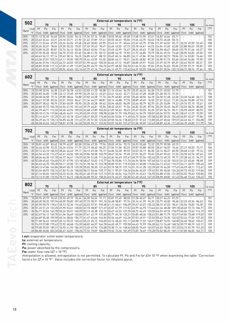
502 External air temperature ta (°F)ta max
(°F)70 75 85 90 95 100 105
Glycol t out Pf Pa Fw Pf Pa Fw Pf Pa Fw Pf Pa Fw Pf Pa Fw Pf Pa Fw Pf Pa Fw
°F (Ton) (kW) (gal/min) (Ton) (kW) (gal/min) (Ton) (kW) (gal/min) (Ton) (kW) (gal/min) (Ton) (kW) (gal/min) (Ton) (kW) (gal/min) (Ton) (kW) (gal/min)35% 15 21,12 32,48 56,65 20,94 33,03 56,16 19,34 37,16 51,88 18,52 39,46 49,68 17,68 41,95 47,41 16,82 44,64 45,11 - - - 10235% 20 23,63 32,44 63,31 23,10 33,71 61,90 21,43 37,89 57,41 20,55 40,23 55,06 19,64 42,75 52,63 18,72 45,48 50,16 - - - 10525% 25 27,12 32,64 69,95 26,24 34,56 67,68 24,40 38,82 62,95 23,43 41,19 60,44 22,42 43,75 57,84 21,39 46,52 55,17 20,33 49,50 52,45 10825% 30 30,26 33,37 78,04 29,30 35,33 75,57 27,33 39,62 70,47 26,26 42,02 67,73 25,18 44,61 64,92 24,04 47,40 62,00 22,88 50,42 59,00 10920% 35 33,85 34,20 85,81 32,76 36,16 83,04 30,63 40,54 77,64 29,45 42,99 74,67 28,24 45,63 71,58 26,98 48,47 68,40 25,75 51,46 65,27 10920% 40 37,90 35,28 90,52 36,70 37,25 87,65 34,38 41,70 82,12 33,08 44,18 79,02 31,73 46,85 75,79 30,34 49,72 72,48 28,90 52,82 69,02 109
45 40,63 36,12 97,14 39,43 38,14 94,25 36,85 42,67 88,10 35,49 45,16 84,85 34,11 47,84 81,54 32,65 50,72 78,04 31,14 53,82 74,44 10950 43,36 37,01 103,74 42,11 39,05 100,75 39,44 43,59 94,35 38,00 46,11 90,91 36,53 48,82 87,39 34,98 51,73 83,68 33,40 54,86 79,90 10955 46,04 37,96 110,23 44,72 40,03 107,07 41,90 44,62 100,32 40,46 47,12 96,87 38,85 49,91 93,03 37,29 52,79 89,29 35,63 55,93 85,31 10960 48,89 39,00 117,16 47,50 41,09 113,81 44,55 45,73 106,74 42,97 48,30 102,96 41,34 51,06 99,06 39,64 54,03 95,00 37,90 57,19 90,81 10965 52,43 40,34 125,72 50,94 42,46 122,16 47,79 47,16 114,61 46,13 49,77 110,62 44,39 52,55 106,46 42,59 55,54 102,13 40,72 58,74 97,64 105
t out: evaporator outlet water temperature; ta: external air temperature; Pf: cooling capacity; Pa: power absorbed by the compressors; Fw: water flow rate (∆T = 10 °F). Interpolation is allowed, extrapolation is not permitted. To calculate Pf, Pa and Fw for ∆T≠ 10 °F when examining the table ”Correction factors for ∆T ≠ 10 °F”. Value includes the correction factor for ethylene glycol.
602 External air temperature ta (°F)ta max
(°F)70 75 85 90 95 100 105
Glycol t out Pf Pa Fw Pf Pa Fw Pf Pa Fw Pf Pa Fw Pf Pa Fw Pf Pa Fw Pf Pa Fw
°F (Ton) (kW) (gal/min) (Ton) (kW) (gal/min) (Ton) (kW) (gal/min) (Ton) (kW) (gal/min) (Ton) (kW) (gal/min) (Ton) (kW) (gal/min) (Ton) (kW) (gal/min)35% 15 23,98 35,96 64,30 23,69 36,78 63,53 22,03 41,20 59,08 21,16 43,64 56,75 20,25 46,24 54,30 19,31 49,02 51,79 - - - 10135% 20 26,83 36,00 71,88 26,12 37,60 69,98 24,35 42,13 65,23 23,41 44,62 62,71 22,42 47,28 60,08 21,40 50,13 57,35 - - - 10425% 25 30,68 36,58 79,14 29,80 38,64 76,88 27,82 43,28 71,76 26,75 45,83 69,02 25,65 48,56 66,18 24,50 51,48 63,20 23,30 54,60 60,11 10825% 30 34,61 37,38 89,24 33,51 39,53 86,41 31,34 44,27 80,81 30,14 46,88 77,74 28,89 49,69 74,50 27,67 52,62 71,35 26,34 55,80 67,93 10920% 35 38,97 38,42 98,79 37,83 40,59 95,90 35,35 45,38 89,62 33,96 48,03 86,09 32,64 50,79 82,75 31,25 53,89 79,23 29,74 57,15 75,41 10920% 40 43,83 39,73 104,70 42,54 41,93 101,62 39,79 46,81 95,04 38,32 49,51 91,54 36,82 52,35 87,94 35,20 55,45 84,07 33,53 58,76 80,08 109
45 46,99 40,71 112,33 45,60 42,94 109,02 42,68 47,89 102,02 41,09 50,63 98,23 39,47 53,55 94,35 37,69 56,74 90,11 35,95 60,07 85,93 10950 50,10 41,76 119,86 48,65 44,01 116,39 45,55 49,02 108,98 43,86 51,79 104,95 42,14 54,75 100,81 40,34 57,92 96,50 38,47 61,29 92,05 10955 53,14 42,91 127,25 51,63 45,18 123,61 48,31 50,25 115,68 46,54 53,06 111,45 44,72 56,06 107,08 42,85 59,26 102,60 40,87 62,67 97,86 10960 56,39 44,13 135,13 54,85 46,38 131,42 51,35 51,50 123,04 49,50 54,34 118,60 47,51 57,43 113,85 45,49 60,66 109,01 43,43 64,11 104,08 10965 60,58 45,65 145,27 58,81 47,98 141,02 55,05 53,17 132,02 53,07 56,03 127,27 51,06 59,09 122,43 48,89 62,36 117,24 46,70 65,83 111,99 106
702 External air temperature ta (°F)ta max
(°F)70 75 85 90 95 100 105
Glycol t out Pf Pa Fw Pf Pa Fw Pf Pa Fw Pf Pa Fw Pf Pa Fw Pf Pa Fw Pf Pa Fw
°F (Ton) (kW) (gal/min) (Ton) (kW) (gal/min) (Ton) (kW) (gal/min) (Ton) (kW) (gal/min) (Ton) (kW) (gal/min) (Ton) (kW) (gal/min) (Ton) (kW) (gal/min)35% 15 30,81 42,87 82,62 30,79 42,87 82,58 29,06 47,35 77,94 28,02 49,94 75,15 26,93 52,68 72,22 25,79 55,58 69,15 - - - 10135% 20 34,46 42,98 92,33 34,26 43,54 91,79 32,19 48,40 86,25 31,06 51,06 83,23 29,87 53,88 80,03 28,61 56,87 76,66 27,31 60,03 73,17 10625% 25 39,12 43,10 100,92 38,44 44,63 99,17 36,13 49,58 93,19 34,86 52,30 89,92 33,53 55,19 86,50 32,14 58,27 82,90 30,68 61,52 79,14 10925% 30 43,54 43,32 112,27 42,41 45,56 109,36 39,86 50,58 102,79 38,47 53,34 99,20 37,01 56,29 95,45 35,49 59,42 91,53 33,90 62,74 87,43 10920% 35 48,04 44,34 121,78 46,77 46,61 118,57 43,96 51,68 111,46 42,45 54,49 107,61 40,79 57,54 103,42 39,12 60,73 99,17 37,38 64,12 94,77 10920% 40 53,00 45,62 126,60 51,57 47,90 123,18 48,47 53,02 115,77 46,78 55,86 111,74 44,96 58,96 107,40 43,13 62,20 103,01 41,23 65,64 98,48 109
45 56,63 46,70 135,38 55,11 49,00 131,74 51,78 54,15 123,78 50,00 57,01 119,53 48,13 60,08 115,06 46,13 63,42 110,27 44,11 66,91 105,44 10950 60,13 47,84 143,86 58,49 50,15 139,95 55,02 55,30 131,63 53,15 58,19 127,16 51,15 61,28 122,39 49,10 64,59 117,47 46,99 68,11 112,41 10955 63,54 48,93 152,14 61,82 51,24 148,03 58,13 56,46 139,17 56,11 59,37 134,36 54,06 62,49 129,45 51,90 65,82 124,26 49,72 69,32 119,06 10960 67,16 50,04 160,93 65,33 52,36 156,55 61,40 57,60 147,13 59,32 60,54 142,15 57,15 63,67 136,95 54,88 67,04 131,50 52,52 70,63 125,84 10965 72,12 51,80 172,94 70,17 54,12 168,26 66,00 59,32 158,26 63,74 62,27 152,85 61,40 65,43 147,25 58,98 68,82 141,43 56,48 72,43 135,43 105
802 External air temperature ta (°F)ta max
(°F)70 75 85 90 95 100 105
Glycol t out Pf Pa Fw Pf Pa Fw Pf Pa Fw Pf Pa Fw Pf Pa Fw Pf Pa Fw Pf Pa Fw
°F (Ton) (kW) (gal/min) (Ton) (kW) (gal/min) (Ton) (kW) (gal/min) (Ton) (kW) (gal/min) (Ton) (kW) (gal/min) (Ton) (kW) (gal/min) (Ton) (kW) (gal/min)35% 15 35,96 49,79 96,45 35,96 49,79 96,44 34,00 54,54 91,17 32,81 57,45 88,00 31,58 60,67 84,71 30,31 64,23 81,29 - - - 10135% 20 40,30 50,25 107,96 40,09 50,82 107,40 37,73 55,91 101,10 36,48 58,81 97,74 35,16 61,99 94,20 33,77 65,50 90,48 32,33 69,36 86,63 10625% 25 45,90 50,75 118,41 45,13 52,34 116,43 42,52 57,51 109,68 41,13 60,41 106,09 39,67 63,57 102,33 38,15 67,03 98,41 36,56 70,82 94,30 10925% 30 51,26 51,22 132,20 49,95 53,61 128,82 47,10 58,87 121,47 45,57 61,79 117,52 43,99 64,95 113,44 42,34 68,38 109,18 40,60 72,13 104,71 10920% 35 56,71 52,54 143,78 55,26 55,01 140,09 52,13 60,38 132,15 50,47 63,32 127,95 48,72 66,49 123,50 46,93 69,92 118,97 45,04 73,63 114,19 10920% 40 62,67 54,12 149,70 61,06 56,69 145,84 57,61 62,19 137,60 55,77 65,18 133,21 53,85 68,36 128,63 51,88 71,79 123,91 49,83 75,48 119,02 109
45 66,89 55,38 159,90 65,16 58,04 155,77 61,47 63,66 146,96 59,54 66,69 142,34 57,53 69,91 137,52 55,43 73,35 132,52 53,26 77,04 127,32 10950 71,00 56,62 169,87 69,14 59,37 165,42 65,22 65,15 156,05 63,16 68,24 151,11 60,98 71,52 145,91 58,87 74,93 140,85 56,60 78,62 135,41 10955 74,93 57,80 179,42 72,92 60,68 174,59 68,82 66,57 164,78 66,65 69,71 159,58 64,43 72,99 154,28 62,13 76,48 148,76 59,77 80,19 143,11 10960 79,00 59,02 189,31 76,95 61,93 184,39 72,65 67,94 174,08 70,38 71,14 168,64 68,05 74,49 163,07 65,65 78,00 157,32 63,15 81,75 151,33 10965 84,80 60,86 203,34 82,67 63,81 198,24 77,92 70,09 186,85 75,52 73,36 181,09 73,09 76,69 175,28 70,52 80,25 169,11 67,85 84,02 162,71 105
TAEe
vo T
ech
19
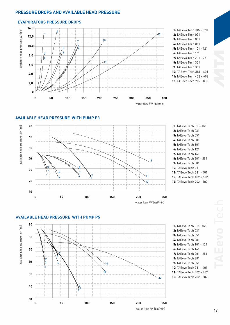
PRESSURE DROPS AND AVAILABLE HEAD PRESSURE
water flow FW [gal/min]
water flow FW [gal/min]
avai
labl
e he
ad p
ress
ure
∆P
[psi
]av
aila
ble
head
pre
ssur
e ∆
P [p
si]
avai
labl
e he
ad p
ress
ure
∆P
[psi
]
1: TAEevo Tech 015 - 020 2: TAEevo Tech 031 3: TAEevo Tech 051 4: TAEevo Tech 081 5: TAEevo Tech 101 6: TAEevo Tech 121 7: TAEevo Tech 161 8: TAEevo Tech 201 - 251 9: TAEevo Tech 30110: TAEevo Tech 35111: TAEevo Tech 381 - 40112: TAEevo Tech 402 ÷ 60213: TAEevo Tech 702 - 802
1: TAEevo Tech 015 - 020 2: TAEevo Tech 031 3: TAEevo Tech 051 4: TAEevo Tech 081 5: TAEevo Tech 101 - 121 6: TAEevo Tech 161 7: TAEevo Tech 201 - 251 8: TAEevo Tech 301 9: TAEevo Tech 35110: TAEevo Tech 381 - 40111: TAEevo Tech 402 ÷ 60212: TAEevo Tech 702 - 802
1: TAEevo Tech 015 - 020 2: TAEevo Tech 031 3: TAEevo Tech 051 4: TAEevo Tech 081 5: TAEevo Tech 101 - 121 6: TAEevo Tech 161 7: TAEevo Tech 201 - 251 8: TAEevo Tech 301 9: TAEevo Tech 35110: TAEevo Tech 381 - 40111: TAEevo Tech 402 ÷ 60212: TAEevo Tech 702 - 802
water flow FW [gal/min]
EVAPORATORS PRESSURE DROPS
AVAILABLE HEAD PRESSURE WITH PUMP P3
AVAILABLE HEAD PRESSURE WITH PUMP P5
8,0
10,0
12,0
14,0
6,0
4,0
2,0
0
70
60
50
40
30
20
10
90
80
70
60
50
40
30
50 100 150 200 250 300 350 4000
50 100 150 200 2500
50 100 150 200 2500
9
11
12
13
2
3
1
5
68
10
4
7
123
4
567
8
910
11
1
23 4
56
78
9
10
11
12
12
TAEe
vo T
ech
20
WORKING LIMITS AND CORRECTION FACTORS
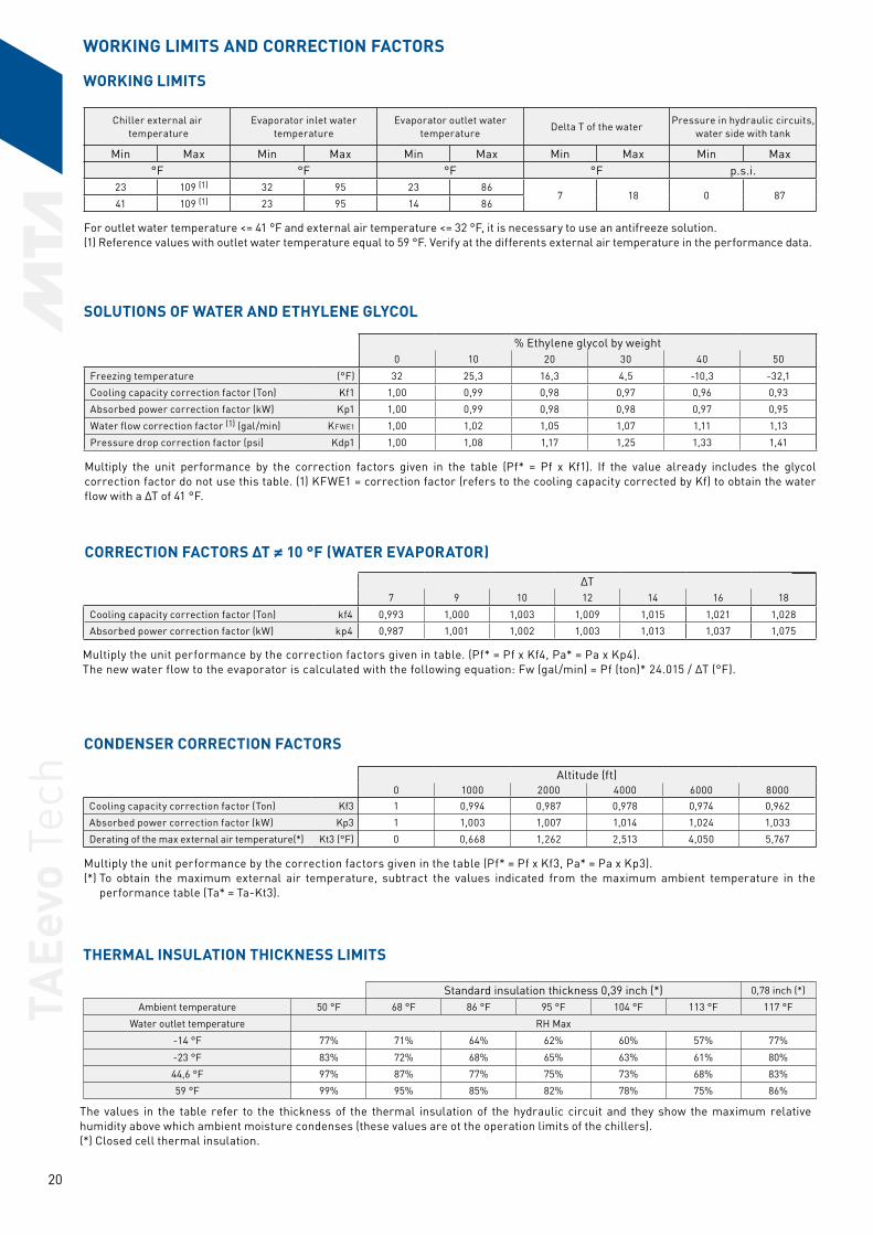
For outlet water temperature <= 41 °F and external air temperature <= 32 °F, it is necessary to use an antifreeze solution.(1) Reference values with outlet water temperature equal to 59 °F. Verify at the differents external air temperature in the performance data.
% Ethylene glycol by weight0 10 20 30 40 50
Freezing temperature (°F) 32 25,3 16,3 4,5 -10,3 -32,1
Cooling capacity correction factor (Ton) Kf1 1,00 0,99 0,98 0,97 0,96 0,93
Absorbed power correction factor (kW) Kp1 1,00 0,99 0,98 0,98 0,97 0,95
Water flow correction factor (1) (gal/min) KFWE1 1,00 1,02 1,05 1,07 1,11 1,13
Pressure drop correction factor (psi) Kdp1 1,00 1,08 1,17 1,25 1,33 1,41
Multiply the unit performance by the correction factors given in the table (Pf* = Pf x Kf1). If the value already includes the glycol correction factor do not use this table. (1) KFWE1 = correction factor (refers to the cooling capacity corrected by Kf) to obtain the water flow with a ∆T of 41 °F.
∆T7 9 10 12 14 16 18
Cooling capacity correction factor (Ton) kf4 0,993 1,000 1,003 1,009 1,015 1,021 1,028
Absorbed power correction factor (kW) kp4 0,987 1,001 1,002 1,003 1,013 1,037 1,075
Multiply the unit performance by the correction factors given in table. (Pf* = Pf x Kf4, Pa* = Pa x Kp4). The new water flow to the evaporator is calculated with the following equation: Fw (gal/min) = Pf (ton)* 24.015 / ∆T (°F).
Altitude (ft)0 1000 2000 4000 6000 8000
Cooling capacity correction factor (Ton) Kf3 1 0,994 0,987 0,978 0,974 0,962
Absorbed power correction factor (kW) Kp3 1 1,003 1,007 1,014 1,024 1,033
Derating of the max external air temperature(*) Kt3 (°F) 0 0,668 1,262 2,513 4,050 5,767
Multiply the unit performance by the correction factors given in the table (Pf* = Pf x Kf3, Pa* = Pa x Kp3). (*) To obtain the maximum external air temperature, subtract the values indicated from the maximum ambient temperature in the
performance table (Ta* = Ta-Kt3).
Chiller external air temperature
Evaporator inlet water temperature
Evaporator outlet water temperature
Delta T of the waterPressure in hydraulic circuits,
water side with tank
Min Max Min Max Min Max Min Max Min Max°F °F °F °F p.s.i.
23 109 (1) 32 95 23 867 18 0 87
41 109 (1) 23 95 14 86
Standard insulation thickness 0,39 inch (*) 0,78 inch (*)
Ambient temperature 50 °F 68 °F 86 °F 95 °F 104 °F 113 °F 117 °F
Water outlet temperature RH Max
-14 °F 77% 71% 64% 62% 60% 57% 77%
-23 °F 83% 72% 68% 65% 63% 61% 80%
44,6 °F 97% 87% 77% 75% 73% 68% 83%
59 °F 99% 95% 85% 82% 78% 75% 86%
The values in the table refer to the thickness of the thermal insulation of the hydraulic circuit and they show the maximum relative humidity above which ambient moisture condenses (these values are ot the operation limits of the chillers).(*) Closed cell thermal insulation.
THERMAL INSULATION THICKNESS LIMITS
CONDENSER CORRECTION FACTORS
SOLUTIONS OF WATER AND ETHYLENE GLYCOL
CORRECTION FACTORS ∆T ≠ 10 °F (WATER EVAPORATOR)
WORKING LIMITS

TAEe
vo T
ech
21
OVERALL DIMENSIONSTAEevo Tech 015 - 020
Axial Fans
TAEevo Tech 031 - 051Axial Fans
N° 2+2 Holes Ø12**
AIRFLOW
14,762,76 2,76 45,47
AIRFLOW
N° 2+2 Holes Ø12**
Note: All TAEevo Tech units are supplied, as standard, with BSP/NPT adapters, supplied together with the unit.
Air vent = 1/2" F NPT
Water discharge = 1/2" F NPT
Holes
Electrical power supply
Tank kit optional§
**015 020 031 051
Water inlet 3/4" F NPT 3/4" F NPT 1”F NPT 1”F NPT
Water outlet 3/4" F NPT 3/4" F NPT 1”F NPT 1”F NPT

TAEe
vo T
ech
22
TAEevo Tech 081Axial Fans
AIRFLOW
N° 2+2 Holes Ø12**
TAEevo Tech 031 - 051Axial Fans and kit tank
AIRFLOW
N° 2+2 Holes Ø12**
Note: All TAEevo Tech units are supplied, as standard, with BSP/NPT adapters, supplied together with the unit.
031 051 081
Water inlet 1”F NPT 1”F NPT 1" 1/2F NPT
Water outlet 1”F NPT 1”F NPT 1" 1/2F NPT
Air vent = 1/2" F NPT
Water discharge = 1/2" F NPT
Holes
Electrical power supply
Tank kit optional§
**

TAEe
vo T
ech
23
TAEevo Tech 081Axial Fans and kit tank
AIRFLOW
N° 2+2 Holes Ø12**
TAEevo Tech 101 - 121 - 161Axial Fans
AIRFLOW
N° 2+2 Holes Ø12**
Note: All TAEevo Tech units are supplied, as standard, with BSP/NPT adapters, supplied together with the unit.
081 101 121 161
Water inlet 1" 1/2F NPT 1" 1/2F NPT 1" 1/2F NPT 1" 1/2F NPT
Water outlet 1" 1/2F NPT 1" 1/2F NPT 1" 1/2F NPT 1" 1/2F NPT
Air vent = 1/2" F NPT
Water discharge = 1/2" F NPT
Holes
Electrical power supply
Tank kit optional§
**

TAEe
vo T
ech
24
TAEevo Tech 101 - 121 - 161Axial Fans and kit tank
AIRFLOW
N° 2+2 Holes Ø12**
TAEevo Tech 201 - 251Axial Fans
AIRFLOW
N° 4+4 Holes Ø20**
Note: All TAEevo Tech units are supplied, as standard, with BSP/NPT adapters, supplied together with the unit.
101 121 161 201 251
Water inlet 1" 1/2F NPT 1" 1/2F NPT 1" 1/2F NPT 2”F NPT 2”F NPT
Water outlet 1" 1/2F NPT 1" 1/2F NPT 1" 1/2F NPT 2”F NPT 2”F NPT
Air vent = 1/2" F NPT
Water discharge = 1/2" F NPT
Holes
Electrical power supply
Tank kit optional§
**
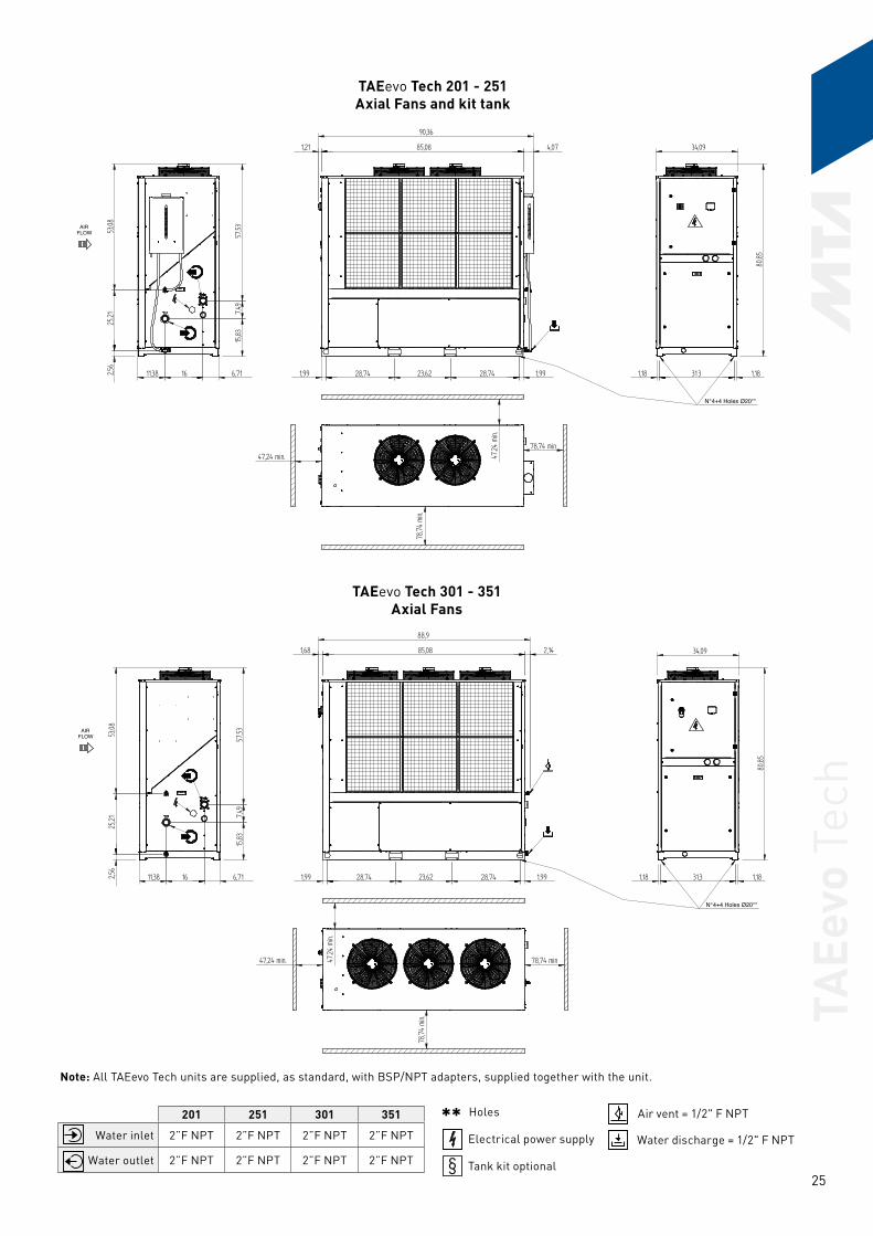
TAEe
vo T
ech
25
TAEevo Tech 201 - 251Axial Fans and kit tank
AIRFLOW
N° 4+4 Holes Ø20**
TAEevo Tech 301 - 351Axial Fans
AIRFLOW
N° 4+4 Holes Ø20**
Note: All TAEevo Tech units are supplied, as standard, with BSP/NPT adapters, supplied together with the unit.
201 251 301 351
Water inlet 2”F NPT 2”F NPT 2”F NPT 2”F NPT
Water outlet 2”F NPT 2”F NPT 2”F NPT 2”F NPT
Air vent = 1/2" F NPT
Water discharge = 1/2" F NPT
Holes
Electrical power supply
Tank kit optional§
**
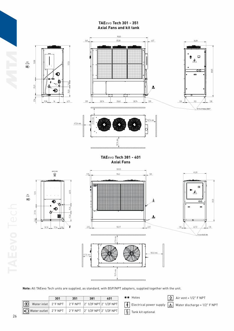
TAEe
vo T
ech
26
TAEevo Tech 301 - 351Axial Fans and kit tank
AIRFLOW
N° 4+4 Holes Ø20**
301 351 381 401
Water inlet 2”F NPT 2”F NPT 2” 1/2F NPT 2” 1/2F NPT
Water outlet 2”F NPT 2”F NPT 2” 1/2F NPT 2” 1/2F NPT
Air vent = 1/2" F NPT
Water discharge = 1/2" F NPT
Holes
Electrical power supply
Tank kit optional§
**
TAEevo Tech 381 - 401Axial Fans
AIRFLOW
HOLESN° 2+2 Ø20
AIR FLOW
Note: All TAEevo Tech units are supplied, as standard, with BSP/NPT adapters, supplied together with the unit.
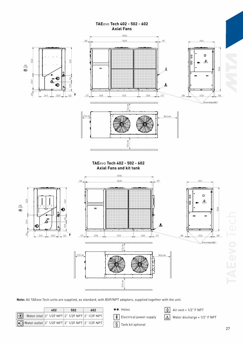
TAEe
vo T
ech
27
TAEevo Tech 402 - 502 - 602Axial Fans
AIRFLOW
N° 4+4 Holes Ø20**
TAEevo Tech 402 - 502 - 602Axial Fans and kit tank
AIRFLOW
N° 4+4 Holes Ø20**
Note: All TAEevo Tech units are supplied, as standard, with BSP/NPT adapters, supplied together with the unit.
402 502 602
Water inlet 2” 1/2F NPT 2” 1/2F NPT 2” 1/2F NPT
Water outlet 2” 1/2F NPT 2” 1/2F NPT 2” 1/2F NPT
Air vent = 1/2" F NPT
Water discharge = 1/2" F NPT
Holes
Electrical power supply
Tank kit optional§
**

TAEe
vo T
ech
28
TAEevo Tech 702 - 802Axial Fans
AIRFLOW
AIRFLOW
AIR FLOW
HOLESN° 4+4 Ø20
Note: All TAEevo Tech units are supplied, as standard, with BSP/NPT adapters, supplied together with the unit.
702 802
Water inlet 3"F NPT 3"F NPT
Water outlet 3"F NPT 3"F NPT
Air vent = 1/2" F NPT
Water discharge = 1/2" F NPT
Holes
Electrical power supply
Tank kit optional§
**

TAEe
vo T
ech
29
INSTALLATION GUIDE
The chillers must be installed in compliance with the following indications:
a) The units must be installed horizontally to ensure correct return of oil to the compressors.
b) Ensure that the clearances prescribed in the catalogue are observed.
c) Position the unit in such a way to minimise the effects of noise emissions, vibration, etc. Specifically, ensure that the units are installed as far as possible from areas in which noise emissions could result in disturbance; in this context do not install the chiller under windows or between two residential units. Vibration transmitted to ground must be reduced by the use of antivibration devices mounted beneath the unit, flexible couplings on the water piping connections and on the trunking containing the electrical power feeding cables.
d) Always hook up the electrical connection of the unit with reference to the wiring diagram supplied with it.
e) Make the hydraulic connections installing the following: - antivibration connections; - shut-off valves (gate valves) to isolate the unit from the hydraulic
circuit; - test points on the inlet and outlet piping for temperature
measurements, to obtain a direct indication of working temperatures; - air venting valves at the highest points of the circuit; - drain valves at the lowest points of the circuit; - pump and expansion vessel (closed circuit) if not already supplied
on the unit; - flow switch (to be supplied by the customer); - strainer (0,02/0,03 inch) at unit inlet to protect the exchanger from
any metal chips or debris in the piping.
f) Install suitable wind screens protecting the condensing coils if the chiller is required to operate with ambient temperatures below 32 °F and if it is envisaged that the condensing coils could be subject to wind velocities greater than 6.6 ft/s.
g) If the application requires cooling capacities greater than the maximum available with a single unit, several chillers can be hydraulically connected in parallel. In this case it is necessary that the units are identical to avoid water flow rates imbalance.
h) It is essential to ensure an adequate volume of air on the intake and delivery sides of the condensing coils. It is also important to avoid recirculation of air between the intake and delivery sides of fans to avoid a reduction of performance or even a shut-down of normal operation. When using several chillers connected in parallel with the condensing coils located face to face on adjacent units, it is essential to maintain sufficient distance between the units. For the minimum distance values refer to the Technical Catalogue.
i) If it is necessary to process water flow rates that are greater than the maximum permissible, it is advisable to set up a by-pass between the chiller inlet and outlet.
l) If it is necessary to process water flow rates that are lower than the minimum permissible, it is advisable to set up a by-pass between the chiller outlet and inlet.
m) Ensure that all the air is bled out of the hydraulic circuit.
n) Always drain the hydraulic circuit during winter shutdowns; alternatively ensure that the circuit is filled with a suitable antifreeze solution. We also recommend running the pumps during brief winter shutdowns and fitting additional electric heaters on the hydraulic circuit piping.

TAEe
vo T
ech
30

5050
ETAE
T601
CA
07-
17
MTA products comply with European safety directives, as recognised by the CE symbol.
MTA is ISO9001 certified, a sign of its commitment to complete customer satisfaction.
MTA partecipates in the E.C.C. programme for LCP-HP. Certified products are listed on:www.eurovent-certification.com.Eurovent Certification applied to the units:- Air/Water with cooling capacity
up to 600 kW- Water/Water up to 1500 kW
M.T.A. S.p.A.Viale Spagna, 8 ZI35020 Tribano (PD) Italy
Tel. +39 049 9588611Fax +39 049 9588676
[email protected] www.mta-it.com
Milan branch officeTel. +39 02 95738492
MTA France S.A.Tel: +33 04 7249 8989www.mtafrance.fr
MTA Deutschland GmbHTel: +49 (2157) 12402 - 0www.mta.de
Novair-MTA, S.A. (España)Tel: +34 938 281 790www.novair-mta.com
SC MTA ROMÂNIA SrlTel: +40 723 022023www.mta-it.ro
MTA USA, LLCTel: +1 716 693 8651www.mta-usa.com
MTA Australasia Pty LtdTel: +61 1300 304 177www.mta-au.com
MTA is represented in over 80 countries worldwide. For information concerning your nearest MTA representative please contact M.T.A. S.p.A.
The continuous improvement of MTA's products can cause some variations in the information herein even without prior notice. Reproduction in whole or in part is forbidden.
The
imag
es o
f the
pro
duct
s in
the
docu
men
t are
for
illus
trat
ive
purp
oses
onl
y an
d th
eref
ore
do n
ot h
ave
any
cont
ract
ual v
alue
.
EAC Declaration
Related Documents