Control4 EA-5 Controller Installation Guide Supported model • C4-EA5 Entertainment and Automation Controller, 5 Zone Introduction The Control4 EA-5 Entertainment and Automation Controller is designed to deliver the ultimate smart home experience, featuring the highest-quality audio of the EA series and processing power to coordinate hundreds of smart devices. The EA-5 can automate sophisticated home theaters, complex interior and exterior lighting scenes, vital security and communications systems, and climate controls for multiple zones. The EA-5 features five independent audio outputs—two digital coaxial, two RCA stereo analog, and one HDMI—with an audiophile-grade signal-to-noise ratio of 118dB. A built-in music server delivers immersive, multi-stream, high-resolution audio with five built-in simultaneous audio streams from your local music collection, a variety of streaming music services, or from AirPlay-enabled devices using native Control4 ShairBridge technology. Expand beyond five streams by including additional EA-5 or EA-3 Controllers. Secure, wireless ZigBee communication; plentiful I/O including IR, serial, contacts and relays; and IP control enable connections to smart home devices such as thermostats, door locks, doorbells, cameras, security panels, sensors, lighting, shades, garage door controllers, irrigation systems, and much more. The sleek design, rack-mount form factor, and top-of-the-line connectivity make the EA-5 the ultimate foundation for any Control4 system and the platform to power the future of your smart home. Box contents The following items are included in the box: • Control4 EA-5 Controller (C4-EA5) • AC power cord • IR emitters (6) • Warranty card • Rack ears (2) • Dual-band antennas (3) • Four-position terminal block for contacts and relays Accessories sold separately • Control4 3.5 mm-to-DB9 Serial Cable (C4-CBL3.5-DB9B) Warnings Caution! To reduce the risk of electrical shock, do not expose this apparatus to rain or moisture. Avertissement ! Pour réduire le risque de choc électrique, n’exposez pas cet appareil à la pluie ou à l’humidité. Caution! In an over-current condition on USB or contact output the software disables the output. If the attached USB device or contact sensor does not appear to power on, remove the device from the controller. Avertissement ! Dans une condition de surintensité sur USB ou sortie de contact le logiciel désactive sortie. Si le périphérique USB ou le capteur de contact connecté ne semble pas s’allumer, retirez le périphérique du contrôleur. For more information, visit the Products pages at www.control4.com. Requirements and specifications Note: We recommend using Ethernet instead of WiFi for the best network connectivity. Note: The Ethernet or WiFi network should be installed before you install the EA-5 Controller. Composer Pro is required to configure this device. See the Composer Pro User Guide (ctrl4.co/cpro-ug) for details. Specifications Model number C4-EA5 Inputs / Outputs Video out 1 video out—1 HDMI Video HDMI 1.4 output; HD 1080p, 50-60 Hz Audio out 5 audio out—1 HDMI, 2 stereo analog, 2 digital coax Audio in 4 audio in—2 stereo analog, 2 digital coax Audio playback formats AAC, AIFF, ALAC, FLAC, M4A, MP2, MP3, MP4/M4A, Ogg Vorbis, PCM, WAV, WMA High-resolution audio playback Up to 192 kHz / 24 bit Advanced audio subsystem Dual audio signal processors, multiple sample rate converters Audio system controls (analog or digital coax) 10-band graphic equalizer, input gain, output gain, loudness, tone controls, balance Signal-to-noise ratio <-118 dBFS Total harmonic distortion 0.00023 (-110 dB) Network Ethernet 10/100/1000BaseT compatible (required for controller setup). Built-in Ethernet switch 1 Ethernet in + 4 gigabit Ethernet switch ports Wireless Dual-Band Wireless-N (2.4GHz, 5GHz, 802.11n/g/b) Wireless security WEP, WPA, and WPA2 Wireless antenna 2 external reverse SMA connectors ZigBee Pro 802.15.4 ZigBee antenna External reverse SMA connector eSATA port 1 eSATA port USB port 1 USB 2.0 port—500mA Control IR OUT 8 IR out—5V 27mA max output 1 IR blaster—front IR capture 1 IR receiver—front; 20-60 KHz SERIAL OUT 4 Serial out—2 DB9 ports and 2 shared with IR out 1-2 Contact 4 contact sensors—30VDC, 1.25A maximum Relay 4 relays—AC: 36V, 2A; DC: 24V, 2A maximum Power Power requirements 100-240 VAC, 60/50Hz Power consumption Max: 40W, 136 BTUs/hour Idle: XXW, XX BTUs/hour Other Operating temperature 32˚ - 104˚ F (0˚ - 40˚ C) Storage temperature 4˚ - 158˚ F (-20˚ - 70˚ C) Fan dB level Max: 35 dB Dimensions (H x W x D) 17.5" (444 mm) x 10.125" (258 mm) x 1.875" (49 mm) w/feet Weight 6.85 lbs (3.10 kg) Shipping weight 9.30 lbs (4.20 kg) Additional resources The following resources are available for more support. • Control4 Knowledgebase: kb.control4.com and Dealer Forums: forums.control4.com • Control4 Technical Support • Control4 website: www.control4.com • Composer Pro documentation in online help or PDF format available on the Dealer Portal under Support: ctrl4.co/docs Front view A Data LED—The LED indicates that the controller is streaming audio. B IR window—IR blaster and IR receiver for learning IR codes. C Caution LED—This LED shows solid red, then blinks blue during the boot process. Note: The Caution LED flashes yellow during the factory restore process. See “Factory Restore” in this document. D Link LED—The blue LED indicates that the controller has been identified in a Control4 Composer project and is communicating with Director. E Power LED—The blue LED indicates that AC power is connected. The controller turns on immediately after power is applied to it. Back view A Power plug port—AC power receptacle for an IEC 60320-C13 power cord. B WIFI 1—Antenna 1 for the WiFi radio. C Contact/Relay port—Connect up to four relay devices and four contact sensor devices to the terminal block connector. Relay connections are COM, NC (normally closed), and NO (normally open). Contact sensor connections are +12, SIG (signal), and GND (ground). D GIGABIT SWITCH—Four port gigabit-ethernet switch to connect other local devices to the network. E ETHERNET IN—RJ-45 jack for a 10/100/1000 BaseT Ethernet connection. F USB—One port for an external USB drive (e.g., FAT32-formatted devices). See “Set up external storage devices” in this document. G E-SATA—One port for an external eSATA drive. See “Set up external storage devices” in this document. H WIFI 2—Antenna 2 for the WiFi radio. I SERIAL—Two serial ports for RS-232 control. See “Connecting the serial ports” in this document. J ID and FACTORY RESET—ID button to identify the device in Composer Pro. FACTORY RESET button to restore the controller to factory defaults. Can also reboot the controller. K HDMI OUT—An HDMI port to display system menus. Also an audio out over HDMI. L IR / SERIAL—Eight 3.5 mm jacks for up to eight IR emitters or for a combination of IR emitters and serial devices. Ports 1 and 2 can be configured independently for serial control or for IR control. See “Setting up IR emitters” in this document for more information. M DIGITAL AUDIO—Two digital coax audio input and two output ports. Allows audio to be shared (IN 1 or 2) over the local network to other Control4 devices. Outputs audio (OUT 1 or 2) shared from other Control4 devices or from digital audio sources (local media or digital streaming services such as TuneIn.) N ANALOG AUDIO—Two stereo audio input and two output ports. Allows audio to be shared (IN 1 or 2) over the local network to other Control4 devices. Outputs audio (OUT 1 or 2) shared from other Control4 devices or from digital audio sources (local media or digital streaming services such as TuneIn.) O ZIGBEE—Antenna for the ZigBee radio. A B C D E A B C D E F G H I J K L M N O Installing the controller To install the controller: 1 Ensure that the home network is in place before starting system setup. The controller requires a network connection, Ethernet (recommended) or WiFi, to use all of the features as designed. When connected, the controller can access web-based media databases, communicate with other IP devices in the home, and access Control4 system updates. 2 Mount the controller in a rack or stacked on a shelf. Always allow plenty of ventilation. See “Mounting the controller in a rack” in this document. 3 Connect the controller to the network. • Ethernet—To connect using an Ethernet connection, plug the data cable from the home network connection into the controller’s RJ-45 port (labeled “ETHERNET IN”) and the network port on the wall or at the network switch. • WiFi—To connect using WiFi, first connect the controller to Ethernet, and then use Composer Pro System Manager to reconfigure the controller for WiFi. Important: Do not install your EA controller on a 172.18.xxx.xxx subnet. 4 Connect system devices. Attach IR and serial devices as described in “Connecting the IR ports/serial ports” and “Setting up IR emitters.” 5 Set up any external storage devices as described in “Setting up external storage devices” in this document. 6 Power up the controller. Plug the power cord into the controller’s power plug port and then into an electrical outlet. Mounting the controller in a rack Using the included rack-mount ears, the EA-5 can easily be mounted in a rack for convenient installation and flexible rack placement. To attach the rack ears to the controller: 1 Remove the three screws in each of the rubber feet on the bottom of the controller. 2 Remove the rubber feet and place the rack ears. The rack ears can be positioned for front or rear rack mounting. 3 Use two of the screws from the rubber feet to secure the rack ears to the controller. Pluggable terminal block connectors For the contact and relay ports, the EA-5 makes use of a pluggable terminal block connector which is a removable plastic part that locks in individual wires (included). To connect a device to the pluggable terminal block: 1 Insert one of the wires required for your device into the appropriate opening in the pluggable terminal block you reserved for that device. 2 Insert the wire: • If using solid-core wire, insert the wire into the hole below the slotted retention tab, and ensure that the wire is tightly secured. • If using stranded wire, press the slotted retention tab in using a small, flat-blade screwdriver. Insert the wire into the hole below the tab, and then release the tab to secure the wire. Example: To add a motion sensor (see Figure 3), connect its wires to the following contact openings: • Power input to +12V • Output signal to SIG • Ground connector to GND Note: To connect dry contact closure devices, such as doorbells, connect the switch between +12V (Power) and SIG (Signal).

Welcome message from author
This document is posted to help you gain knowledge. Please leave a comment to let me know what you think about it! Share it to your friends and learn new things together.
Transcript
Control4 EA-5 ControllerInstallation Guide
Supported model• C4-EA5 Entertainment and Automation Controller, 5 Zone
IntroductionThe Control4 EA-5 Entertainment and Automation Controller is designed to deliver the ultimate smart home experience, featuring the highest-quality audio of the EA series and processing power to coordinate hundreds of smart devices. The EA-5 can automate sophisticated home theaters, complex interior and exterior lighting scenes, vital security and communications systems, and climate controls for multiple zones.
The EA-5 features five independent audio outputs—two digital coaxial, two RCA stereo analog, and one HDMI—with an audiophile-grade signal-to-noise ratio of 118dB. A built-in music server delivers immersive, multi-stream, high-resolution audio with five built-in simultaneous audio streams from your local music collection, a variety of streaming music services, or from AirPlay-enabled devices using native Control4 ShairBridge technology. Expand beyond five streams by including additional EA-5 or EA-3 Controllers.
Secure, wireless ZigBee communication; plentiful I/O including IR, serial, contacts and relays; and IP control enable connections to smart home devices such as thermostats, door locks, doorbells, cameras, security panels, sensors, lighting, shades, garage door controllers, irrigation systems, and much more. The sleek design, rack-mount form factor, and top-of-the-line connectivity make the EA-5 the ultimate foundation for any Control4 system and the platform to power the future of your smart home.
Box contents
The following items are included in the box:
• Control4 EA-5 Controller (C4-EA5)• AC power cord• IR emitters (6)• Warranty card• Rack ears (2)• Dual-band antennas (3)• Four-position terminal block for contacts and relays
Accessories sold separately• Control4 3.5 mm-to-DB9 Serial Cable (C4-CBL3.5-DB9B)
WarningsCaution! To reduce the risk of electrical shock, do not expose this apparatus to rain or moisture.
Avertissement ! Pour réduire le risque de choc électrique, n’exposez pas cet appareil à la pluie ou à l’humidité.
Caution! In an over-current condition on USB or contact output the software disables the output. If the attached USB device or contact sensor does not appear to power on, remove the device from the controller.
Avertissement ! Dans une condition de surintensité sur USB ou sortie de contact le logiciel désactive sortie. Si le périphérique USB ou le capteur de contact connecté ne semble pas s’allumer, retirez le périphérique du contrôleur.
For more information, visit the Products pages at www.control4.com.
Requirements and specificationsNote: We recommend using Ethernet instead of WiFi for the best network connectivity.
Note: The Ethernet or WiFi network should be installed before you install the EA-5 Controller.
Composer Pro is required to configure this device. See the Composer Pro User Guide (ctrl4.co/cpro-ug) for details.
Specifications
Model number C4-EA5
Inputs / Outputs
Video out 1 video out—1 HDMI
Video HDMI 1.4 output; HD 1080p, 50-60 Hz
Audio out 5 audio out—1 HDMI, 2 stereo analog, 2 digital coax
Audio in 4 audio in—2 stereo analog, 2 digital coax
Audio playback formats AAC, AIFF, ALAC, FLAC, M4A, MP2, MP3, MP4/M4A, Ogg Vorbis, PCM, WAV, WMA
High-resolution audio playback Up to 192 kHz / 24 bit
Advanced audio subsystem Dual audio signal processors, multiple sample rate converters
Audio system controls (analog or digital coax)
10-band graphic equalizer, input gain, output gain, loudness, tone controls, balance
Signal-to-noise ratio <-118 dBFS
Total harmonic distortion 0.00023 (-110 dB)
Network
Ethernet 10/100/1000BaseT compatible (required for controller setup).
Built-in Ethernet switch 1 Ethernet in + 4 gigabit Ethernet switch ports
Wireless Dual-Band Wireless-N (2.4GHz, 5GHz, 802.11n/g/b)
Wireless security WEP, WPA, and WPA2
Wireless antenna 2 external reverse SMA connectors
ZigBee Pro 802.15.4
ZigBee antenna External reverse SMA connector
eSATA port 1 eSATA port
USB port 1 USB 2.0 port—500mA
Control
IR OUT 8 IR out—5V 27mA max output1 IR blaster—front
IR capture 1 IR receiver—front; 20-60 KHz
SERIAL OUT 4 Serial out—2 DB9 ports and 2 shared with IR out 1-2
Contact 4 contact sensors—30VDC, 1.25A maximum
Relay 4 relays—AC: 36V, 2A; DC: 24V, 2A maximum
Power
Power requirements 100-240 VAC, 60/50Hz
Power consumption Max: 40W, 136 BTUs/hourIdle: XXW, XX BTUs/hour
Other
Operating temperature 32˚ - 104˚ F (0˚ - 40˚ C)
Storage temperature 4˚ - 158˚ F (-20˚ - 70˚ C)
Fan dB level Max: 35 dB
Dimensions (H x W x D) 17.5" (444 mm) x 10.125" (258 mm) x 1.875" (49 mm) w/feet
Weight 6.85 lbs (3.10 kg)
Shipping weight 9.30 lbs (4.20 kg)
Additional resourcesThe following resources are available for more support.
• Control4 Knowledgebase: kb.control4.com and Dealer Forums: forums.control4.com
• Control4 Technical Support• Control4 website: www.control4.com• Composer Pro documentation in online help or PDF format available
on the Dealer Portal under Support: ctrl4.co/docs
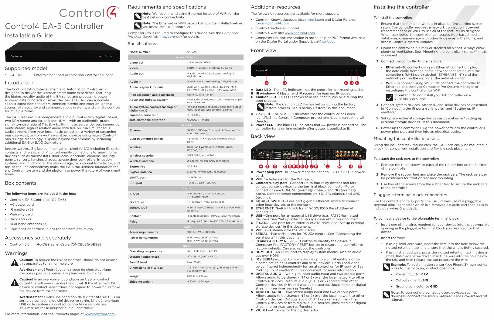
Front view
A Data LED—The LED indicates that the controller is streaming audio.B IR window—IR blaster and IR receiver for learning IR codes.C Caution LED—This LED shows solid red, then blinks blue during the
boot process. Note: The Caution LED flashes yellow during the factory restore process. See “Factory Restore” in this document.
D Link LED—The blue LED indicates that the controller has been identified in a Control4 Composer project and is communicating with Director.
E Power LED—The blue LED indicates that AC power is connected. The controller turns on immediately after power is applied to it.
Back view
A Power plug port—AC power receptacle for an IEC 60320-C13 power cord.
B WIFI 1—Antenna 1 for the WiFi radio.C Contact/Relay port—Connect up to four relay devices and four
contact sensor devices to the terminal block connector. Relay connections are COM, NC (normally closed), and NO (normally open). Contact sensor connections are +12, SIG (signal), and GND (ground).
D GIGABIT SWITCH—Four port gigabit-ethernet switch to connect other local devices to the network.
E ETHERNET IN—RJ-45 jack for a 10/100/1000 BaseT Ethernet connection.
F USB—One port for an external USB drive (e.g., FAT32-formatted devices). See “Set up external storage devices” in this document.
G E-SATA—One port for an external eSATA drive. See “Set up external storage devices” in this document.
H WIFI 2—Antenna 2 for the WiFi radio.I SERIAL—Two serial ports for RS-232 control. See “Connecting the
serial ports” in this document.J ID and FACTORY RESET—ID button to identify the device in
Composer Pro. FACTORY RESET button to restore the controller to factory defaults. Can also reboot the controller.
K HDMI OUT—An HDMI port to display system menus. Also an audio out over HDMI.
L IR / SERIAL—Eight 3.5 mm jacks for up to eight IR emitters or for a combination of IR emitters and serial devices. Ports 1 and 2 can be configured independently for serial control or for IR control. See “Setting up IR emitters” in this document for more information.
M DIGITAL AUDIO—Two digital coax audio input and two output ports. Allows audio to be shared (IN 1 or 2) over the local network to other Control4 devices. Outputs audio (OUT 1 or 2) shared from other Control4 devices or from digital audio sources (local media or digital streaming services such as TuneIn.)
N ANALOG AUDIO—Two stereo audio input and two output ports. Allows audio to be shared (IN 1 or 2) over the local network to other Control4 devices. Outputs audio (OUT 1 or 2) shared from other Control4 devices or from digital audio sources (local media or digital streaming services such as TuneIn.)
O ZIGBEE—Antenna for the ZigBee radio.
A B C D E
A B C D E F G H I J K L M N O
Installing the controller
To install the controller:
1 Ensure that the home network is in place before starting system setup. The controller requires a network connection, Ethernet (recommended) or WiFi, to use all of the features as designed. When connected, the controller can access web-based media databases, communicate with other IP devices in the home, and access Control4 system updates.
2 Mount the controller in a rack or stacked on a shelf. Always allow plenty of ventilation. See “Mounting the controller in a rack” in this document.
3 Connect the controller to the network.
• Ethernet—To connect using an Ethernet connection, plug the data cable from the home network connection into the controller’s RJ-45 port (labeled “ETHERNET IN”) and the network port on the wall or at the network switch.
• WiFi—To connect using WiFi, first connect the controller to Ethernet, and then use Composer Pro System Manager to reconfigure the controller for WiFi.
Important: Do not install your EA controller on a 172.18.xxx.xxx subnet.
4 Connect system devices. Attach IR and serial devices as described in “Connecting the IR ports/serial ports” and “Setting up IR emitters.”
5 Set up any external storage devices as described in “Setting up external storage devices” in this document.
6 Power up the controller. Plug the power cord into the controller’s power plug port and then into an electrical outlet.
Mounting the controller in a rackUsing the included rack-mount ears, the EA-5 can easily be mounted in a rack for convenient installation and flexible rack placement.
To attach the rack ears to the controller:
1 Remove the three screws in each of the rubber feet on the bottom of the controller.
2 Remove the rubber feet and place the rack ears. The rack ears can be positioned for front or rear rack mounting.
3 Use two of the screws from the rubber feet to secure the rack ears to the controller.
Pluggable terminal block connectorsFor the contact and relay ports, the EA-5 makes use of a pluggable terminal block connector which is a removable plastic part that locks in individual wires (included).
To connect a device to the pluggable terminal block:
1 Insert one of the wires required for your device into the appropriate opening in the pluggable terminal block you reserved for that device.
2 Insert the wire:
• If using solid-core wire, insert the wire into the hole below the slotted retention tab, and ensure that the wire is tightly secured.
• If using stranded wire, press the slotted retention tab in using a small, flat-blade screwdriver. Insert the wire into the hole below the tab, and then release the tab to secure the wire.
Example: To add a motion sensor (see Figure 3), connect its wires to the following contact openings:
• Power input to +12V
• Output signal to SIG
• Ground connector to GND
Note: To connect dry contact closure devices, such as doorbells, connect the switch between +12V (Power) and SIG (Signal).
control4.com | 888.400.4070
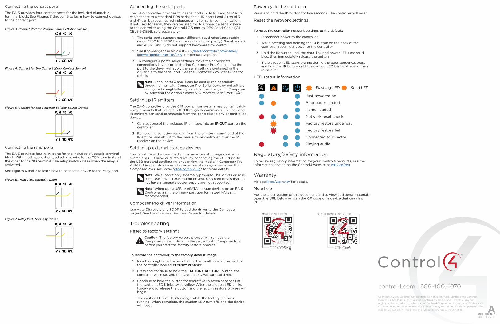
Connecting the contact ports
The EA-5 provides four contact ports for the included pluggable terminal block. See Figures 3 through 5 to learn how to connect devices to the contact port.
Figure 3. Contact Port for Voltage Source (Motion Sensor)
Figure 4. Contact for Dry Contact (Door Contact Sensor)
Figure 5. Contact for Self-Powered Voltage Source Device
Connecting the relay ports
The EA-5 provides four relay ports for the included pluggable terminal block. With most applications, attach one wire to the COM terminal and the other to the NO terminal. The relay switch closes when the relay is activated.
See Figures 6 and 7 to learn how to connect a device to the relay port.
Figure 6. Relay Port, Normally Open
Figure 7. Relay Port, Normally Closed
Connecting the serial portsThe EA-5 controller provides four serial ports. SERIAL 1 and SERIAL 2 can connect to a standard DB9 serial cable. IR ports 1 and 2 (serial 3 and 4) can be reconfigured independently for serial communication. If not used for serial, they can be used for IR. Connect a serial device to the controller using the Control4 3.5 mm-to-DB9 Serial Cable (C4-CBL3.5-DB9B, sold separately).
1 The serial ports support many different baud rates (acceptable range: 1200 to 115200 baud for odd and even parity). Serial ports 3 and 4 (IR 1 and 2) do not support hardware flow control.
2 See Knowledgebase article #268 (dealer.control4.com/dealer/knowledgebase/article/268) for pinout diagrams.
3 To configure a port’s serial settings, make the appropriate connections in your project using Composer Pro. Connecting the port to the driver will apply the serial settings contained in the driver file to the serial port. See the Composer Pro User Guide for details.
Note: Serial ports 3 and 4 can be configured as straight-through or null with Composer Pro. Serial ports by default are configured straight-through and can be changed in Composer by selecting the option Enable Null-Modem Serial Port (3/4).
Setting up IR emittersThe EA-5 controller provides 8 IR ports. Your system may contain third-party products that are controlled through IR commands. The included IR emitters can send commands from the controller to any IR-controlled device.
1 Connect one of the included IR emitters into an IR OUT port on the controller.
2 Remove the adhesive backing from the emitter (round) end of the IR emitter and affix it to the device to be controlled over the IR receiver on the device.
Setting up external storage devicesYou can store and access media from an external storage device, for example, a USB drive or eSata drive, by connecting the USB drive to the USB port and configuring or scanning the media in Composer Pro. A NAS drive can also be used as an external storage device, see the Composer Pro User Guide (ctrl4.co/cpro-ug) for more details.
Note: We support only externally powered USB drives or solid-state USB drives (USB thumb drives). USB hard drives that do not have a separate power supply are not supported.
Note: When using USB or eSATA storage devices on an EA-5 Controller, a single primary partition formatted FAT32 is recommended.
Composer Pro driver informationUse Auto Discovery and SDDP to add the driver to the Composer project. See the Composer Pro User Guide for details.
TroubleshootingReset to factory settings
Caution! The factory restore process will remove the Composer project. Back up the project with Composer Pro before you start the factory restore process
To restore the controller to the factory default image:
1 Insert a straightened paper clip into the small hole on the back of the controller labeled FACTORY RESTORE.
2 Press and continue to hold the FACTORY RESTORE button, the controller will reset and the caution LED will turn solid red.
3 Continue to hold the button for about five to seven seconds until the caution LED blinks twice yellow. After the caution LED blinks twice yellow, release the button and the factory restore process will begin.
The caution LED will blink orange while the factory restore is running. When complete, the caution LED turn offs and the device will reset.
Power cycle the controllerPress and hold the ID button for five seconds. The controller will reset.
Reset the network settings
To reset the controller network settings to the default:
1 Disconnect power to the controller.
2 While pressing and holding the ID button on the back of the controller, reconnect power to the controller.
3 Hold the ID button until the data, link and power LEDs are solid blue, then immediately release the button.
4 If the caution LED stays orange during the boot sequence, press and hold the ID button until the caution LED blinks blue, and then release it.
LED status information
Just powered on
Bootloader loaded
Kernel loaded
Network reset check
Factory restore underway
Factory restore fail
Connected to Director
Playing audio
Regulatory/Safety informationTo review regulatory information for your Control4 products, see the information located on the Control4 website at ctrl4.co/reg.
WarrantyVisit ctrl4.co/warranty for details.
More help
For the latest version of this document and to view additional materials, open the URL below or scan the QR code on a device that can view PDFs.
—Flashing LED —Solid LED
MOST RECENT VERSION
ctrl4.co/ea5-ig
MORE INFO ON EA CONTROLLERS
ctrl4.co/ea
200-00382-A 2016-01-25 DH
Copyright ©2016, Control4 Corporation. All rights reserved. Control4, the Control4 logo, the 4-ball logo, 4Store, 4Sight, Control4 My Home, and Everyday Easy are registered trademarks or trademarks of Control4 Corporation in the United States and/or other countries. All other names and brands may be claimed as the property of their respective owners. All specifications subject to change without notice. A
Related Documents