GEARS & TRANSMISSIONS Workshop paper I [ 3 ] Faculdade de Engenharia da Universidade do Porto, Portugal, 5 th June 2003 Contact fatigue of carbonitrided and shot-peened gears. Effects of residual stresses A.C. Batista 1 , A.M. Dias 2 1 Department of Physics, University of Coimbra, P-3004-516 Coimbra, Portugal, [email protected] 2 Department of Mechanical Engineering, University of Coimbra - Polo II, P-3030-201 Coimbra, Portugal, [email protected] ABSTRACT: The X-ray diffraction technique was used to characterise the evolution of residual stresses, during contact fatigue tests of carbo-nitrided and shot-peened gears from an automotive gearbox. A numerical model was developed to predict residual stress relaxation and to estimate the most probable site of contact fatigue crack initiation, using multiaxial fatigue criteria. An experimental method combining the X-ray diffraction stress analysis and the electric resistance strain gauge technique was used to determine the mechanical characteristics of the surface-treated layers. The Dang Van multiaxial fatigue criterion was used to estimate the most probable depth of contact fatigue crack initiation, taking account of the influence of residual stresses, roughness and friction. Introduction Contact fatigue may affect numerous mechanisms, such as bearings and gears. If the parts work under sufficiently high contact load situations, a progressive irreversible degradation of their surface, like pitting or spalling, can be observed. Contact fatigue pitting and spalling are commonly attributed to the repeated traverse of a Hertzian stress field over the same material volume, primarily under rolling contact conditions (with relatively little sliding) in which other competing failure modes are less likely to lead to earlier failure. The study of this phenomenon is very complex since its mechanisms have not yet been clearly defined. Several parameters have to be considered, ranging from the material characteristics to the surface and environment conditions. In the automotive industry this phenomenon particularly affects gears. After the progress achieved in the field of metallurgy (fatigue and fracture of gear teeth) and lubrication (wear and seizing), the improvement of modern gearboxes has come up against this phenomenon, encountered in heavy duty conditions.

Welcome message from author
This document is posted to help you gain knowledge. Please leave a comment to let me know what you think about it! Share it to your friends and learn new things together.
Transcript
GEARS & TRANSMISSIONS Workshop paper I [ 3 ]
Faculdade de Engenharia da Universidade do Porto, Portugal, 5th June 2003
Contact fatigue of carbonitrided and shot-peened gears. Effects of residual stresses
A.C. Batista1, A.M. Dias2 1 Department of Physics, University of Coimbra, P-3004-516 Coimbra, Portugal, [email protected] 2 Department of Mechanical Engineering, University of Coimbra - Polo II, P-3030-201 Coimbra, Portugal, [email protected]
ABSTRACT: The X-ray diffraction technique was used to characterise the evolution of residual stresses, during
contact fatigue tests of carbo-nitrided and shot-peened gears from an automotive gearbox. A numerical model was
developed to predict residual stress relaxation and to estimate the most probable site of contact fatigue crack
initiation, using multiaxial fatigue criteria. An experimental method combining the X-ray diffraction stress analysis
and the electric resistance strain gauge technique was used to determine the mechanical characteristics of the
surface-treated layers. The Dang Van multiaxial fatigue criterion was used to estimate the most probable depth of
contact fatigue crack initiation, taking account of the influence of residual stresses, roughness and friction.
Introduction
Contact fatigue may affect numerous mechanisms, such as bearings and gears. If the parts
work under sufficiently high contact load situations, a progressive irreversible degradation of
their surface, like pitting or spalling, can be observed. Contact fatigue pitting and spalling are
commonly attributed to the repeated traverse of a Hertzian stress field over the same material
volume, primarily under rolling contact conditions (with relatively little sliding) in which other
competing failure modes are less likely to lead to earlier failure.
The study of this phenomenon is very complex since its mechanisms have not yet been clearly
defined. Several parameters have to be considered, ranging from the material characteristics to
the surface and environment conditions. In the automotive industry this phenomenon particularly
affects gears. After the progress achieved in the field of metallurgy (fatigue and fracture of gear
teeth) and lubrication (wear and seizing), the improvement of modern gearboxes has come up
against this phenomenon, encountered in heavy duty conditions.

[ 4 ] paper I GEARS 2003
Faculdade de Engenharia da Universidade do Porto, Portugal, 5th June 2003
This study aims to develop a numerical model that enables the prediction of the behaviour of
surface treated mechanical components submitted to contact fatigue. It covers the most important
aspects highlighted in the literature review, given below:
• Use of the X-ray diffraction technique to study the evolution of different mechanical and
metallurgical parameters as a function of the damage.
• Development or adaptation of methods to identify the mechanical behaviour laws of
surface treated materials.
• Development of a numerical model enabling the prediction of residual stress evolution.
• Use of multiaxial fatigue criteria to predict the initiation site of contact fatigue damage,
taking account of residual stresses and roughness.
The model will later be used to study the contact fatigue damage on gears from an automotive
gearbox.
State of the art
Contact fatigue
The pioneering experimental investigation on the contact fatigue phenomenon was conducted
by Way [1]. Since then various researchers have studied the problem from different points of
view. No conclusive theory has yet been established because of the complexity of the
phenomenon, which is influenced by factors such as contact stresses [2, 3], lubrication film
specific thickness [4, 5], surface topography and the interactions between asperities [6, 7],
residual stresses [8-10] and surface tractions [11]. All these studies show the complexity of the
problem, as well as the difficulty of establishing rules applicable to different mechanisms or
configurations.
In his work, using the same gears and surface treatments as those used here, Pedron [12]
covered various aspects ranging from the mechanisms of damage initiation and evolution to the
identification of the most influential parameters. Dufourg [13] studied the influence of
metallurgical aspects on the contact fatigue damage of carbo-nitrided gears. This author found
that, in general, contact fatigue cracks are initiated at the free surface. Dufourg also analysed the
microstructure evolution. He separated the thermal and mechanical effects by submitting samples
to an isothermal tempering equivalent in temperature and time to the average conditions during

GEARS & TRANSMISSIONS Workshop paper I [ 5 ]
Faculdade de Engenharia da Universidade do Porto, Portugal, 5th June 2003
gear tests. He thus observed the decomposition of high carbon content primary martensite, noting
that, although the thermal effect may by itself explain the decomposition, the mechanical effect
facilitated it and made it more complete.
Influence of residual stresses on contact fatigue
Resistance to fatigue is largely influenced by manufacturing processes and surface treatments,
which can modify the mechanical, geometrical and metallurgical characteristics of the near
surface layers and introduce a gradient of residual stresses between the surface and the bulk
material. With contact fatigue, as with classic fatigue, compressive residual stresses can increase
the life of the components, as they delay crack initiation and propagation [14, 15]. Attention
must be paid not only to the surface residual stresses, but also to the residual stress values and the
gradient shape in the internal layers. Indeed, maximum contact fatigue stresses are often located
below the surface, which may induce in-depth crack initiation.
Multiaxial fatigue criteria must be used in contact fatigue life analysis, since residual stresses
and contact fatigue stresses are always multiaxial. One commonly used criterion is that of Dang
Van [16] which predicts the absence of fatigue crack initiation, if:
(1)
where represents the microscopic shear stress, the hydrostatic pressure, t the time and T
the load cycle period. The constants α and β are characteristics of the material and may be
obtained from rotating bending and torsion fatigue tests.
As contact fatigue crack initiation is a local phenomenon, fatigue criteria should be applied
locally, keeping in mind the fatigue strength, residual stresses and loading stresses at each depth.
The parameters of the criteria are usually only known for the material of the treated surface and
the bulk material, and not for the intermediate layers. Some authors [17] overcome this problem
by assuming an in-depth evolution for fatigue resistance similar to that observed for hardness or
X-ray diffraction peak breadth (related to strain hardening).
[ 6 ] paper I GEARS 2003
Faculdade de Engenharia da Universidade do Porto, Portugal, 5th June 2003
Residual stress relaxation
Residual stress relaxation can occur when the components are submitted to mechanical or
thermal loading. It also depends on the material and on the type of surface treatment that
generated the residual stresses.
Relaxation of residual stresses caused by mechanical surface treatments, like shot-peening, is
basically conditioned by dislocation movement converting the elastic residual strains, associated
with residual stresses, into micro-plastic strains [18]. For residual stresses produced by thermal
or thermochemical treatments, stress relaxation is a function of the possibility of dislocation
movement, and of the stability of the metallurgical structure. Any modification to the
microstructure leads to a modification of the distribution of residual stresses.
Residual stress relaxation should be taken into account in fatigue life analysis. During the
design phase, unfortunately, this relaxation is often poorly understood and may only be assessed
by fatigue tests and the experimental determination of residual stresses. Otherwise, reference
may be made to results found in the literature for similar materials and treatments. Some efforts
have been made to develop numerical residual stress relaxation models, ranging from the
simplest [19-21] to more complex theoretical models [22, 23], but there is still some more work
to be done in this area.
Characterisation of mechanical properties in surface-treated materials
Surface hardening treatments modify the mechanical elastic-plastic properties of the surface
layers. Knowledge of the mechanical characteristics of the surface layers is very important for
estimating the mechanical behaviour of the treated parts. The hardness test is commonly used to
estimate qualitative changes in the mechanical properties of those layers. For applications such as
numerical analysis, however, the actual elastic-plastic behaviour has to be known.
The local mechanical properties cannot be determined by classical mechanical tests, due to the
difficulty of obtaining samples with a homogeneous cross-section representative of the affected
layers. For surface-treated materials, with different properties over the cross-section, a method
based on locally measured parameters is necessary.
Some indirect methods have been used by different authors, based on the elasto-plastic
analysis of spherical indentation profiles [24], or on the local yield stress estimation by means of
GEARS & TRANSMISSIONS Workshop paper I [ 7 ]
Faculdade de Engenharia da Universidade do Porto, Portugal, 5th June 2003
nanoindentation measurements combined with compression tests [25]. Other authors have
proposed the estimation of the mechanical properties from the in-depth distribution of the X-ray
diffraction peak broadening [23]. Nevertheless, these methods are of limited application, either
because they have not been experimentally validated or because they are not very accurate and
still need some improvement.
Materials and experimental techniques
Materials
The gears used in this study were made of AISI 4130 steel. The chemical composition of the
material is as follows (%wt): C = 0.27, Mn = 0.73, Cr = 1.10, Mo = 0.25, Si ≤ 0.40, Cu ≤ 0.30,
Ni ≤ 0.30, Al ≤ 0.050, P ≤ 0.025 and S = 0.030. The parts were studied after two different types
of surface treatments: (i) carbo-nitriding, and (ii) carbo-nitriding followed by shot-peening.
The carbo-nitriding treatment was performed in a controlled atmosphere of nitrogen, methane,
natural gas and ammonia gas, for a period of 3 hours. During this time the samples went through
five industrial furnaces, at constant temperatures within the range 790˚C to 880˚C. The carbo-
nitriding treatment was finished by a quenching in oil at 140˚C, for 5 minutes.
The shot-peening treatment was performed using steel shot S110 (58 HRC) and a pressure of
about 6 bar, with a total projection time of 60 seconds. This treatment induces a small increase of
the surface roughness values of gear teeth, from 0.23 µm to 0.25 µm for Ra, and from 1.5 µm to
1.7 µm for Rz.
The surface treatments were chosen to obtain two completely different in-depth residual stress
profiles for the same metallurgy. This would permit the influence of the residual stresses on
contact fatigue damage to be evaluated.
Contact fatigue tests
Contact fatigue tests were carried out on a gearbox simulator developed by Renault SA. This
equipment permits the testing of the gears from a Renault JB4 gearbox under service conditions.
Both the transmitted torque and the temperature of the lubrication oil can be defined.
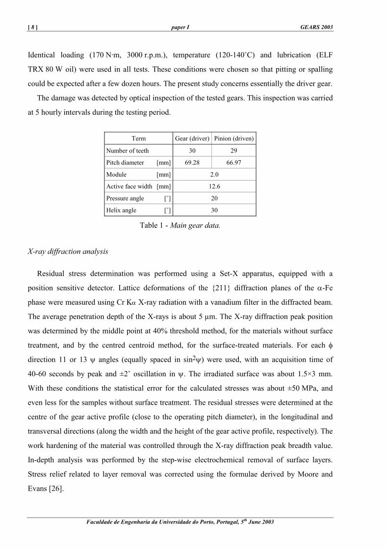
Geometrical details of the helical gears used in this study are shown in Table 1. Tooth flanks
were finished by “shaving”. Both the driver and the driven gear have similar hardness profiles.
[ 8 ] paper I GEARS 2003
Faculdade de Engenharia da Universidade do Porto, Portugal, 5th June 2003
Identical loading (170 N·m, 3000 r.p.m.), temperature (120-140˚C) and lubrication (ELF
TRX 80 W oil) were used in all tests. These conditions were chosen so that pitting or spalling
could be expected after a few dozen hours. The present study concerns essentially the driver gear.
The damage was detected by optical inspection of the tested gears. This inspection was carried
at 5 hourly intervals during the testing period.
Term Gear (driver) Pinion (driven)
Number of teeth 30 29
Pitch diameter [mm] 69.28 66.97
Module [mm] 2.0
Active face width [mm] 12.6
Pressure angle [˚] 20
Helix angle [˚] 30
Table 1 - Main gear data.
X-ray diffraction analysis
Residual stress determination was performed using a Set-X apparatus, equipped with a
position sensitive detector. Lattice deformations of the {211} diffraction planes of the α-Fe
phase were measured using Cr Kα X-ray radiation with a vanadium filter in the diffracted beam.
The average penetration depth of the X-rays is about 5 µm. The X-ray diffraction peak position
was determined by the middle point at 40% threshold method, for the materials without surface
treatment, and by the centred centroid method, for the surface-treated materials. For each φ
direction 11 or 13 ψ angles (equally spaced in sin2ψ) were used, with an acquisition time of
40-60 seconds by peak and ±2˚ oscillation in ψ. The irradiated surface was about 1.5×3 mm.
With these conditions the statistical error for the calculated stresses was about ±50 MPa, and
even less for the samples without surface treatment. The residual stresses were determined at the
centre of the gear active profile (close to the operating pitch diameter), in the longitudinal and
transversal directions (along the width and the height of the gear active profile, respectively). The
work hardening of the material was controlled through the X-ray diffraction peak breadth value.
In-depth analysis was performed by the step-wise electrochemical removal of surface layers.
Stress relief related to layer removal was corrected using the formulae derived by Moore and
Evans [26].

GEARS & TRANSMISSIONS Workshop paper I [ 9 ]
Faculdade de Engenharia da Universidade do Porto, Portugal, 5th June 2003
The volume fraction of retained austenite was determined by X-ray diffraction quantitative
analysis, using a Philips goniometer equipped with a proportional detector. X-ray Cr Kα
radiation was used, with a vanadium filter in the diffracted beam. The diffraction planes used
were the {200} and {211} of the α-Fe phase, and the {200} and {220} of the γ-Fe phase. The
irradiated surface was about 2×3 mm.
Morphology of surface damage to the gears
Fatigue tests were performed for up to 30 hours for the carbo-nitrided only gears and for up to
65 hours for the gears with an additional shot-peening treatment. In the carbo-nitrided only gears,
the damage appeared after about 20 hours of testing, in the form of pitting and spalling, in a
restricted area below the operating pitch diameter, near the lower limit of the active profile
(Figure 1). During the first phase of their formation the spalls usually show an arrowhead
configuration, typical for surface origin spalling. With the continuation of tests, the spalls
increased in number and size, which could reach several square millimetres. An increase of the
pit size was also observed.
As regards the gears with an additional shot-peening treatment, the damage appears after the
same test time, but in the form of micropitting, starting below the operating pitch diameter and
then spreading to the upper part of the active profile. Some pitting appeared later, in a more
restricted area close to the lower limit of the active profile. After 65 hours, the gear teeth also
presented some spalls with dimensions of less than 0.5 mm2.
It can be concluded that damage to the gears appears after about the same testing time for both
kinds of surface treatment, but in different forms: pitting and spalling for the carbo-nitrided only
gears, and micropitting for the carbo-nitrided and shot-peened gears. Figure 2 shows a scheme of
the damage observed on the gears with both types of surface treatments.
The maximum spalling depth was around 140 µm after 30 hours, for the carbo-nitrided only
gears, and 60 µm after 65 hours of testing for the carbo-nitrided plus shot-peened gears. Dufourg
[13] carried out tests for up to 52 hours, on the same type of carbo-nitrided only gears, under the
same test conditions. According to his results, increasing the test time led to an increase in
maximum spalling depth, though this did not exceed 300 µm. These results indicate a reasonable
difference in contact fatigue crack propagation for the carbo-nitrided gears with and without
shot-peening.

[ 10 ] paper I GEARS 2003
Faculdade de Engenharia da Universidade do Porto, Portugal, 5th June 2003
Figure 1 - Examples of (a) pitting and (b) spalling observed on the carbo-nitrided only gears, after 20 hours of contact fatigue testing.
Figure 2 - Scheme of the damage observed on the gears: (a) carbo-nitrided only, and (b) with an additional shot-peening treatment.
Microstructure and residual stress state evolution during contact fatigue tests
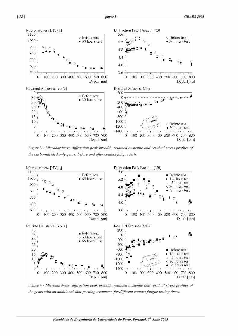
The X-ray diffraction technique was used to characterise the surface-treated layers, in terms of
diffraction peak breadth, retained austenite and residual stresses. The respective in-depth
distributions are shown in Figures 3 and 4, for both surface treatments.
X-ray diffraction peak broadening and retained austenite
Before contact fatigue testing, the in-depth distributions of the X-ray diffraction peak breadth
for the martensitic phase were similar for both surface treatments. It shows a maximum value at a
depth of 150 µm, where the retained austenite content shows a marked decrease, stabilising at a
depth of 600 µm. This evolution can be attributed: (i) to the strain adaptation during the heat
treatment, allowed by the high retained austenite content (30-35 vol % at the surface), at depths
of less than 150 µm, and (ii) to the decrease in the carbon content of the martensite, at depths of
more than 150 µm, since there is no more retained austenite. According to the diffraction peak
GEARS & TRANSMISSIONS Workshop paper I [ 11 ]
Faculdade de Engenharia da Universidade do Porto, Portugal, 5th June 2003
breadth profile, the thickness of the carbo-nitrided layer is about 600 µm, which is confirmed by
microhardness data. The additional shot-peening treatment generates a considerable phase
transformation of the retained austenite in the first 150 µm of the carbo-nitrided layer. This
transformation induces a hardening of the material in the first 150 µm, which is in agreement
with microhardness data. The diffraction peak breadth does not show this phenomenon, because
our results only concern the diffraction peak breadth of the martensitic phase, which remains
basically the same.
During the contact fatigue tests the evolution of the diffraction peak breadth is similar for both
surface treatments. A decrease over the first 300 µm was observed, indicating a softening of the
materials, which agrees with microhardness data. The decrease begins after the first few minutes
and takes place during the first 30 hours. Examples of this behaviour are presented in Figures 3
and 4 for the gears with both surface treatments.
At the end of the contact fatigue tests, the carbo-nitrided plus shot-peened gears showed the
smallest diffraction peak breadth values, indicating a greater softening for this material. This
phenomenon may be linked to the lower residual austenite content in the surface layer
(10-15 vol %), relative to the carbo-nitrided only gears (30-35 vol %). The cyclic strain is then
mainly sustained by the martensitic phase, resulting in a more significant softening in the
material with an additional shot-peening treatment.
The carbo-nitrided only gears seemed to undergo a partial transformation of the retained
austenite in the near surface layers. This is essentially due to the cyclic strain effect [13]. The
carbo-nitrided plus shot-peened gears did not exhibit any retained austenite transformation since
the less stable austenite had already been transformed by the shot-peening treatment.
[ 12 ] paper I GEARS 2003
Faculdade de Engenharia da Universidade do Porto, Portugal, 5th June 2003
Figure 3 - Microhardness, diffraction peak breadth, retained austenite and residual stress profiles of the carbo-nitrided only gears, before and after contact fatigue tests.
Figure 4 - Microhardness, diffraction peak breadth, retained austenite and residual stress profiles of the gears with an additional shot-peening treatment, for different contact fatigue testing times.

GEARS & TRANSMISSIONS Workshop paper I [ 13 ]
Faculdade de Engenharia da Universidade do Porto, Portugal, 5th June 2003
Residual stresses
The in-depth residual stress profiles for the carbo-nitrided gears are quite similar for the
longitudinal and transverse directions of the teeth's active profile. The carbo-nitriding treatment
introduces a constant value of residual stresses of about -300 MPa in the first 250 µm, followed
by a slow decrease of the compressive stresses up to a depth of 600 µm. After 30 hours of
contact fatigue testing the compressive residual stresses have only increased in a layer very close
to the surface, and do not show any significant evolution at depths superior to 10 µm. Figure 3
shows an example of the in-depth distribution of residual stresses for the carbo-nitrided only
pinions.
The additional shot-peening treatment also develops compressive residual stresses which
reach a maximum value of about -1200 MPa, at a depth of 30-50 µm, followed by a plateau with
higher compressive stresses than those on the carbo-nitrided samples. A significant residual
stress relaxation was observed during the contact fatigue tests. The relaxation started after only a
few minutes and was mainly completed after the first 5 hours of testing. After longer testing (65
hours), the maximum level of compressive stresses occurred at the surface. Figure 4 gives an
example of the residual stress evolution for the carbo-nitrided plus shot-peened gears.
The stabilised residual stress profile of the carbo-nitrided plus shot-peened gears shows higher
compressive stresses in the first 100 µm than the carbo-nitrided only gears. This difference could
contribute to the delayed development of spalling in the shot-peened gears, as compressive
residual stresses slow down the propagation of cracks [14, 15], essential for the development of
spalling.
Figure 5 - Schematic view of the four-point bending apparatus during a compression test of the surface-treated layer.
[ 14 ] paper I GEARS 2003
Faculdade de Engenharia da Universidade do Porto, Portugal, 5th June 2003
Characterisation of mechanical properties in the surface-hardened layers
The following sections describe the determination of the stress-strain laws for hardened
surface layers, using two different methods.
Method combining the X-ray diffraction stress analysis and electric resistance strain gauge
technique
An experimental procedure has been developed for the determination of stress-strain laws of
materials presenting a gradient of mechanical characteristics across the surface layers [27, 28]. It
is based on the determination of stresses and strains by X-ray diffraction and strain gauges,
respectively, as a function of loading during 4-point bending tests:
(i) Flat samples are submitted to increasing loading in a 4-point bending mounting, as shown
in Figure 5.
(ii) The evolution of the stresses and the applied macroscopic strains in the surface of the
samples are determined by X-ray diffraction and strain gauges, respectively, as a function
of the bending moment.
Since the penetration depth of X-rays is very small and the strain is directly determined by
strain gauges at the surface, the determined stress-strain law is characteristic of the analysed
surface.
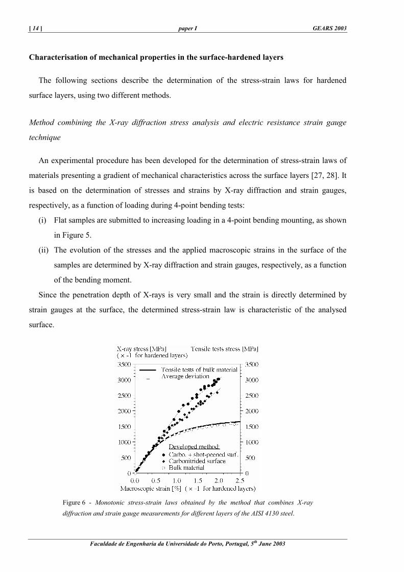
Figure 6 - Monotonic stress-strain laws obtained by the method that combines X-ray diffraction and strain gauge measurements for different layers of the AISI 4130 steel.

GEARS & TRANSMISSIONS Workshop paper I [ 15 ]
Faculdade de Engenharia da Universidade do Porto, Portugal, 5th June 2003
The method was applied to the surface layers and bulk material of samples submitted to the
same surface treatments as the gears. The core material was studied after removing the surface
hardened layers by electrolytic polishing. The monotonic stress-strain curves obtained for the
treated surface and for the bulk material are shown in Figure 6. Tensile tests were also carried out
for the bulk material. A good agreement between the developed method and the tensile tests was
observed for the bulk material, confirming the reliability of the method. In this way monotonic
stress-strain laws could be experimentally determined before contact fatigue.
Method combining spherical indentation tests with a numerical elasto-plastic analysis of the
indentation process
The mechanical properties of materials can be obtained from a comparison between
experimental indentation profiles and profiles obtained by a numerical elasto-plastic analysis of
the indentation process [24].
Indentation tests were performed for different maximal contact pressures in order to describe
the elastic-plastic behaviour of the material. To avoid singularities and to have an easily
modelled contact, spherical indentation was chosen. The experimental residual indentation radius
and depth were determined for each indentation profile using a profilometer. The indentation
tests have been performed using alumina spheres, with diameters of 2.5 mm and 20 mm.
The indentation test is modelled in axial symmetry, on the finite element code presented in the
next section, thereby obtaining a numerical indentation profile that is a function of the
mechanical characteristics introduced in the model. In our case, the sample is assumed to consist
of two different layers: one representative of the surface hardened material layer, with 300 µm
depth, and a second one simulating the bulk material. The bulk material properties used were
those obtained from tensile tests. The elasto-plastic characteristics of the surface layer are then
progressively adjusted in the numerical model until the calculated profile is sufficiently close to
the experimental one. The action of the indentator is taken into account by the contact pressure
distribution. The friction was not considered. The finite element mesh was defined with a high
element density in the contact zone. The element size was about 20 µm at the centre of the
axisymmetric contact.
The method was validated by applying it to the hardened surface layer of the gears with both
surface treatments, before contact fatigue loading. Good agreement was found with the

[ 16 ] paper I GEARS 2003
Faculdade de Engenharia da Universidade do Porto, Portugal, 5th June 2003
experimental results obtained by the combined X-ray diffraction and strain gauge measurements,
described above.
Indentation tests and modelling were also performed on the gears after contact fatigue
softening, in order to determine the cyclic elasto-plastic characteristics of the treated layers. The
example given in Figure 7 presents some of the results obtained for the surface of the hardened
layers. Some softening occurred in both materials during contact fatigue testing. This
phenomenon is more pronounced for the material with an additional shot-peening treatment,
which is in agreement with X-ray diffraction peak breadth evolution.
Figure 7 - Cyclic stress-strain laws obtained for the surface-treated layers of the AISI 4130 steel by a numerical analysis of spherical indentation tests.
Numerical model for predicting residual stress relaxation and the most probable site of
contact fatigue crack initiation
A numerical model has been developed for predicting residual stress relaxation and the most
probable site of contact fatigue crack initiation. It has been developed for IBM PC compatible
microcomputers from the two-dimensional finite element code ACORD.2D. The program
permits a choice to be made between axial-symmetry and plane strain condition, and uses a
kinematic hardening law to describe the elastic-plastic material behaviour. It is structured in four
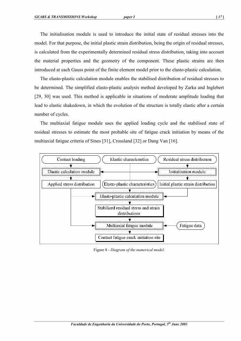
modules (Figure 8).
The elastic calculation module determines the distribution of the applied stresses from the
contact pressure distribution, assuming a linear-elastic material behaviour.
GEARS & TRANSMISSIONS Workshop paper I [ 17 ]
Faculdade de Engenharia da Universidade do Porto, Portugal, 5th June 2003
The initialisation module is used to introduce the initial state of residual stresses into the
model. For that purpose, the initial plastic strain distribution, being the origin of residual stresses,
is calculated from the experimentally determined residual stress distribution, taking into account
the material properties and the geometry of the component. These plastic strains are then
introduced at each Gauss point of the finite element model prior to the elasto-plastic calculation.
The elasto-plastic calculation module enables the stabilised distribution of residual stresses to
be determined. The simplified elasto-plastic analysis method developed by Zarka and Inglebert
[29, 30] was used. This method is applicable in situations of moderate amplitude loading that
lead to elastic shakedown, in which the evolution of the structure is totally elastic after a certain
number of cycles.
The multiaxial fatigue module uses the applied loading cycle and the stabilised state of
residual stresses to estimate the most probable site of fatigue crack initiation by means of the
multiaxial fatigue criteria of Sines [31], Crossland [32] or Dang Van [16].
Figure 8 - Diagram of the numerical model.
[ 18 ] paper I GEARS 2003
Faculdade de Engenharia da Universidade do Porto, Portugal, 5th June 2003
Modelling of residual stress relaxation
The developed model was used to predict the stabilised residual stress distribution of gears
after contact fatigue loading.
The LDP software [33] was used to calculate the contact load distribution between gear teeth,
assuming a linear-elastic behaviour. The results indicate values of about 1450 MPa for the
maximum contact pressure at the centre of the active profile and about 1300 MPa in the damage
initiation zone. The corresponding values for the contact half-width are in the order of 145 µm
and 110 µm, respectively.
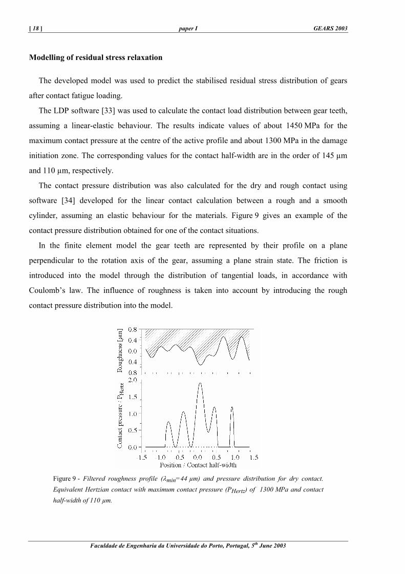
The contact pressure distribution was also calculated for the dry and rough contact using
software [34] developed for the linear contact calculation between a rough and a smooth
cylinder, assuming an elastic behaviour for the materials. Figure 9 gives an example of the
contact pressure distribution obtained for one of the contact situations.
In the finite element model the gear teeth are represented by their profile on a plane
perpendicular to the rotation axis of the gear, assuming a plane strain state. The friction is
introduced into the model through the distribution of tangential loads, in accordance with
Coulomb’s law. The influence of roughness is taken into account by introducing the rough
contact pressure distribution into the model.
Figure 9 - Filtered roughness profile (λmin=44 µm) and pressure distribution for dry contact. Equivalent Hertzian contact with maximum contact pressure (PHertz) of 1300 MPa and contact half-width of 110 µm.
GEARS & TRANSMISSIONS Workshop paper I [ 19 ]
Faculdade de Engenharia da Universidade do Porto, Portugal, 5th June 2003
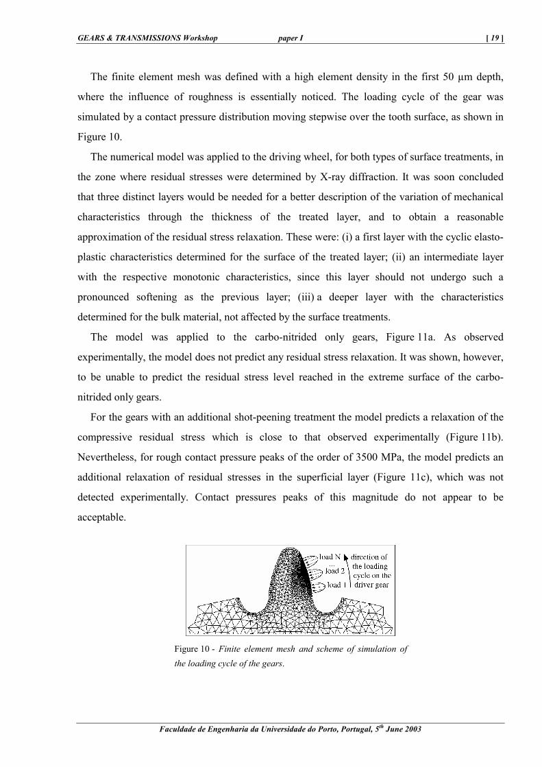
The finite element mesh was defined with a high element density in the first 50 µm depth,
where the influence of roughness is essentially noticed. The loading cycle of the gear was
simulated by a contact pressure distribution moving stepwise over the tooth surface, as shown in
Figure 10.
The numerical model was applied to the driving wheel, for both types of surface treatments, in
the zone where residual stresses were determined by X-ray diffraction. It was soon concluded
that three distinct layers would be needed for a better description of the variation of mechanical
characteristics through the thickness of the treated layer, and to obtain a reasonable
approximation of the residual stress relaxation. These were: (i) a first layer with the cyclic elasto-
plastic characteristics determined for the surface of the treated layer; (ii) an intermediate layer
with the respective monotonic characteristics, since this layer should not undergo such a
pronounced softening as the previous layer; (iii) a deeper layer with the characteristics
determined for the bulk material, not affected by the surface treatments.
The model was applied to the carbo-nitrided only gears, Figure 11a. As observed
experimentally, the model does not predict any residual stress relaxation. It was shown, however,
to be unable to predict the residual stress level reached in the extreme surface of the carbo-
nitrided only gears.
For the gears with an additional shot-peening treatment the model predicts a relaxation of the
compressive residual stress which is close to that observed experimentally (Figure 11b).
Nevertheless, for rough contact pressure peaks of the order of 3500 MPa, the model predicts an
additional relaxation of residual stresses in the superficial layer (Figure 11c), which was not
detected experimentally. Contact pressures peaks of this magnitude do not appear to be
acceptable.
Figure 10 - Finite element mesh and scheme of simulation of the loading cycle of the gears.

[ 20 ] paper I GEARS 2003
Faculdade de Engenharia da Universidade do Porto, Portugal, 5th June 2003
Figure 11 - Comparison of the calculated residual stress relaxation with the experimental values, for: (a) the carbo-nitrided only gears (smooth contact), and for the gears with an additional shot-peening treatment, considering the (b) smooth contact and (c) the rough contact with Pmax=2.7 PHertz.
Estimate of contact fatigue crack initiation
The Dang Van multiaxial fatigue criterion was used to estimate the most probable depth of
contact fatigue crack initiation. Calculations were performed on the damage zone of the gears,
between the operating pitch diameter and the lower limit of the active profile, using the
distribution of applied stresses and the stabilised state of residual stresses determined by the
GEARS & TRANSMISSIONS Workshop paper I [ 21 ]
Faculdade de Engenharia da Universidade do Porto, Portugal, 5th June 2003
numerical model. The α and β criterion parameters were determined experimentally [35]. The
same parameters were used through the entire thickness of the surface-treated layers.
The results are presented in the form of the in-depth distribution of the parameter
(τ+αp-β)critical, defined in Figure 12. Contact fatigue crack initiation takes place, preferentially,
where this parameter is positive or presents its maximum value.
Figure 13a shows some of the results obtained for the smooth contact. They indicate greater
damage to the material below the surface, inside the treated layer. The analysis shows that
Hertzian loading does not justify the contact fatigue crack initiation observed experimentally at
the surface. Even with the introduction of friction, the model only predicts the initiation of
fatigue cracks for friction coefficients of about 0.5 or higher, which does not appear to be
acceptable for the lubricated contact.
Considering the contact pressure distribution due to rough contact, it was observed that the
influence of roughness essentially affects the first 50 µm below the surface, Figures 13b and 13c.
The model now indicates greater damage in the surface or its immediate vicinity, which agrees
with experimental observations. Nevertheless, it can be noted that the model requires high values
of the friction coefficient (Figure 13b) or high contact pressure peaks (Figure 13c) to predict
crack initiation, which does not appear to be acceptable. In fact, for contact pressures of this
magnitude, the model predicts an additional relaxation of residual stresses in the superficial
layer, which was not detected experimentally. This analysis shows that contact fatigue crack
initiation cannot be completely explained by the combined action of roughness and friction
alone.
The analysis predicts a lower damage level for the material with an additional shot-peening
treatment, because of the more intense compressive residual stresses in the first 100 µm.
However, it was observed experimentally that damage initiates at similar test times for the gears
with both surface treatments, although the development of spalling was delayed for the shot-
peened gears. These results indicate that residual stresses preferentially control the propagation
of contact fatigue cracks. The initiation of cracks can, furthermore, depend on other factors, such
as geometric surface irregularities (here only considered through the contact pressure
distribution) or singularities of the metallurgical microstructure, and is not exclusively attributed
to mechanical parameters.

[ 22 ] paper I GEARS 2003
Faculdade de Engenharia da Universidade do Porto, Portugal, 5th June 2003
Figure 12 - Definition of the parameter (τ+αp-β)critical.
Figure 13 - Results of the Dang Van criterion for the damage initiation zone of the gears, for: (a) smooth contact with PHertz=1.3 GPa, µ=0.1; (b) rough contact with Pmax=1.6·PHertz, µ=0.4; (c) rough contact with Pmax=2.7·PHertz, µ=0. Dry contact is assumed.

GEARS & TRANSMISSIONS Workshop paper I [ 23 ]
Faculdade de Engenharia da Universidade do Porto, Portugal, 5th June 2003
Conclusions
The aim of this work was to study the contact fatigue damage of gears from an automotive
gearbox, submitted to combined treatments of carbo-nitriding and shot-peening. The
experimental results show an evolution of the near surface layers during contact fatigue tests,
indicated by gradual changes in the residual stresses and in the X-ray diffraction peak breadth.
The residual stress relaxation takes place during the first few hours of testing. The X-ray
diffraction peak breadth evolution indicates a softening of the treated layers, more pronounced
for the material with an additional shot-peening treatment.
The damage appears after the same testing time for both kinds of surface treatments, but the
development of spalling is delayed in the gears with an additional shot-peening treatment. This
may be due to the higher level of compressive residual stresses in the surface layer of those gears.
The results as a whole suggest that the influence of residual stresses is related more to the
propagation of contact fatigue cracks than to their initiation.
The stress-strain laws of the surface-treated layers were determined by means of two separate
methods, based on locally measured parameters. Cyclic loading led to a softening of the most
superficial layer, with the most pronounced effect for the material with an additional shot-
peening treatment.
A numerical model was developed to predict the residual stress relaxation and the most
probable site of contact fatigue crack initiation, taking account of the influence of roughness and
friction.
The calculated residual stress relaxation showed a reasonable agreement with experimental
data. However, the gradient of the mechanical characteristics over the thickness of the surface-
treated layer needs to be described with close approximation, in order to obtain good results.
The Dang Van multiaxial fatigue criterion predicts a higher probability of damage in the
surface of the gears or in its immediate vicinity, as confirmed by experimental data, when the
rough contact pressure distribution is taken into account. Initiation of contact fatigue cracks,
however, cannot be easily justified by the combined action of roughness and friction alone.
[ 24 ] paper I GEARS 2003
Faculdade de Engenharia da Universidade do Porto, Portugal, 5th June 2003
References
[1] S. Way, "Pitting due to rolling contact", Journal of Applied Mechanics, Vol. 2, pp. A49-A58, 1935.
[2] G. Lundberg, A. Palmgren, "Dynamic capacity of rolling bearings", Journal of Applied Mechanics, Vol. 16, pp.
165-172, 1949.
[3] J.E. Merwin, K.L. Johnson, "An analysis of plastic deformation in rolling contact", Proceedings of the
Institution of Mechanical Engineers, Vol. 177, pp. 679-690, 1963.
[4] P.H. Dawson, "Effect of metallic contact on the pitting of lubricated rolling surfaces", Journal of Mechanical
Engineering Science, Vol. 4, pp. 16-21, 1962.
[5] J.Y. Liu, T.E. Tallian, J.I. McCool, "Dependence of bearing fatigue life on film thickness to surface roughness
ratio", ASLE Transactions, Vol. 18, Nr. 2, pp. 144-152, 1975.
[6] K. Ichimaru, A. Nakajima, F. Hirano, "Effect of asperity interaction on pitting in rollers and gears",
Transactions of the ASME, Journal of Mechanical Design, Vol. 103, pp. 482-491, April 1981.
[7] N. Yamashita, T. Mura, H.S. Cheng, "Effect of stresses induced by a spherical asperity on surface pitting in
elastohydrodynamic contacts", ASLE Transactions, Vol. 28, Nr. 1, pp. 11-20, 1985.
[8] H. Muro, T. Tsushima, M. Nagafuchi, "Initiation and propagation of surface cracks in rolling fatigue of high
hardness steel", Wear, Vol. 35, pp. 261-282, 1975.
[9] S.S. Cretu, N.G. Popinceanu, "Influence of residual stresses induced by plastic deformation on rolling contact
fatigue", Wear, Vol. 105, pp. 153-170, 1985.
[10] X. Hongbin, C. Qing, S. Eryu, W. Dengzhen, C. Zhaohong, W. Zhengle, "The effect of shot peening on rolling
contact fatigue behaviour and its crack initiation and propagation in carburized steel", Wear, Vol. 151, pp. 77-
86, 1991.
[11] N. Soda, T. Yamamoto, "Effect of tangential traction and roughness on crack initiation/propagation during
rolling contact", ASLE Transactions, Vol. 25, pp. 198-206, 1982.
[12] J.P. Pedron, "Approche des problèmes de fatigue de surface dans l'industrie automobile", La Revue de
Métallurgie - CIT, pp. 193-203, February 1990.
[13] X. Dufourg, "Pitting des engrenages de boite de vitesse: caractérisation microstructurale avant et après essai de
fatigue d'endurance", Ph.D. Thesis, Université de Paris-Sud, Orsay, France, December 1992.
[14] H. Gray, L. Wagner, G. Lütjering, "Influence of residual stresses on fatigue crack propagation of small surface
cracks", Residual Stresses in Science and Technology, Vol. 2, DGM, pp. 815-822, 1987.
[15] M.T. Hanson, L.M. Keer, "An analytical life prediction model for the crack propagation occuring in contact
fatigue failure", STLE Tribology Transactions, Vol. 35, Nr. 3, pp. 451-461, 1992.
[16] K. Dang Van, "Sur la résistance à la fatigue des métaux", Sciences et Techniques de l'Armement, Mémorial de
l'Artillerie Française, Vol. 47, Nr. 3, pp. 641-722, 1973.
GEARS & TRANSMISSIONS Workshop paper I [ 25 ]
Faculdade de Engenharia da Universidade do Porto, Portugal, 5th June 2003
[17] A. Deperrois, L. Castex, K. Dang Van, P. Merrien, A. Bignonnet, "High cycle fatigue life of surface hardened
steels under multi-axial loading", Fatigue 90, Honolulu, July 1990.
[18] O. Vöhringer, "Relaxation of residual stresses", Residual Stresses, Edited by E. Macherauch and V. Hauk,
DGM, pp. 47-80, 1986.
[19] S. Kodama, "The behaviour of residual stress during fatigue stress cycles", International Conference on
Mechanical Behaviour of Materials, Kyoto, Japan, Vol. 2, pp. 111-118, August 1971.
[20] M.R. James, "The relaxation of residual stresses during fatigue", Symposium on Residual Stress and Stress
Relaxation, Edited by E. Kula and V. Weiss, Plenum Press, pp. 297-314, 1982.
[21] J. Bergström, "Residual stress and microstructural behaviour of a shot peened steel in fatigue. An X-ray
diffraction study", Ph.D. Thesis, Linköping Institute of Technology, Sweden, 1986.
[22] J. Lu, J.F. Flavenot, "Prediction of residual stress relaxation during fatigue loading and taking residual stresses
in a multiaxial fatigue criteria into account", Second International Conference on Residual Stresses, Nancy,
France, Edited by G. Beck et al, Elsevier Applied Science, pp. 784-790, November 1988.
[23] W. Cao, L. Castex, "Modelling of the shot peening residual stress relaxation in steel structure under cyclic
loading", Second International Conference on Residual Stresses, Nancy, France, Edited by G. Beck et al,
Elsevier Applied Science, pp. 631-636, 1988.
[24] P. Virmoux, G. Inglebert, R. Gras, "Characterisation of elastic-plastic behaviour for contact purposes on
surface hardened materials", Dissipative Processes in Tribology, Edited by D. Dowson et al., Elsevier Science
BV, pp. 287-301, 1994.
[25] H. Elghazal, G. Dudragne, D. Girodin, A. Hamel, G. Lormand, A. Vincent, "Etude du comportement d'aciers
cémentés sollicités en fatigue de contact", 17èmes Journées de Printemps, Fatigue de Contact, Senlis, France,
Société Francaise de Métallurgie et de Matériaux, pp. 27.1-27.12, May 1998.
[26] M.G. Moore, W.P. Evans, "Mathematical correction for stress in removed layers in X-ray diffraction residual
stress analysis", SAE Transactions, Vol. 66, pp. 340-345, 1958.
[27] A.C. Batista, "Deterioração por fadiga de contacto de engrenagens tratadas superficialmente", Ph.D. Thesis,
University of Coimbra, Portugal, 1997.
[28] A.C. Batista, A.M. Dias, "Characterisation of mechanical properties in surface-treated materials", Journal of
Testing and Evaluation, JTEVA, Vol. 28, Nr. 3, pp. 217-223, May 2000.
[29] J. Zarka, J. Casier, "Elastic-plastic response of a structure to cyclic loading: practical rules", Mechanics Today,
Edited by S. Nemat-Nasser, Vol. 6, Pergamon Press, New York, USA, pp. 93-198, 1979.
[30] G. Inglebert, J. Frelat, "Quick analysis of inelastic structures using a simplified method", Nuclear Engineering
and Design, Nr. 116, pp. 281-291, 1989.
[31] G. Sines, "Behavior of metals under complex stresses", Metal Fatigue, Edited by G. Sines and J.L. Waisman,
McGraw-Hill, pp. 145-169, 1959.
[ 26 ] paper I GEARS 2003
Faculdade de Engenharia da Universidade do Porto, Portugal, 5th June 2003
[32] B. Crossland, "Effect of large hydrostatic pressures on the torsional fatigue strength of an alloy steel",
International Conference on Fatigue of Metals, IME/ASME, Londres, UK, pp. 138-149, 1956.
[33] "LDP - Load Distribution Program", Version 8.1, Gear Dynamics and Gear Noise Research Laboratory, Ohio
State University, USA, 1992.
[34] "Normal Contact Calculation Between Elastic Solids", CETRIB-INEGI, Faculty of Engineering, University of
Porto, Portugal, 1992.
[35] "Internal Report", Renault S.A., France, 1995.
GEARS & TRANSMISSIONS Workshop paper I [ 27 ]
Faculdade de Engenharia da Universidade do Porto, Portugal, 5th June 2003

[ 28 ] paper I GEARS 2003
Faculdade de Engenharia da Universidade do Porto, Portugal, 5th June 2003
Related Documents
![Contact fatigue of carbonitrided and shot-peened gears. Effects … - ACastanhola... · 2003-06-20 · GEARS & TRANSMISSIONS Workshop paper I [ 3 ] Faculdade de Engenharia da Universidade](https://static.cupdf.com/doc/110x72/5f85f3e09a911f79f76b33c4/contact-fatigue-of-carbonitrided-and-shot-peened-gears-effects-acastanhola.jpg)