Concrete properties of a 1904 Hennebique reinforced concrete viaduct A. Hellebois & B. Espion Department of Building, Architecture and Town Planning (Laboratory of Civil Engineering), Université Libre de Bruxelles, Belgium Abstract Our study focuses on the material properties of a 107-year-old reinforced concrete viaduct, called viaduct of Colo-Hugues, in Braine-l’Alleud (near Brussels, Belgium), designed by the well known Hennebique’s office in 1904. Parameters investigated include determination of the concrete strength by means of Schmidt rebound hammer tests correlated with compression of core samples, Young modulus, carbonation depth with phenolphthalein semi-destructive and destructive testing and concrete permeability. This experimental research was performed to analyse the influence between the results of carbonation depth and the compressive strength for the first generation of reinforced concrete through a representative case study. Keywords: material characterisation, modern heritage, historic reinforced concrete, Hennebique system. 1 Introduction The pathologies affecting reinforced concrete (r.c.) structures are similar and identifiable in many constructions independently of their dates of construction. However, design methods and execution technologies have extensively changed from the first applications of reinforced concrete elements at the turn of the 20 th century until now. To the best of our knowledge, little has been published on the mechanical and physical properties of reinforced concrete built before the 1 st World War [1, 2]. However, the durability issues constitute crucial questions requiring urgent answers for properly preserving this early reinforced concrete heritage. To fulfil this lack of data, this paper focuses on the properties of a 107- Structural Repairs and Maintenance of Heritage Architecture XII 589 www.witpress.com, ISSN 1743-3509 (on-line) WIT Transactions on The Built Environment, Vol 118, © 2011 WIT Press doi:10.2495/ 10491 STR1

Welcome message from author
This document is posted to help you gain knowledge. Please leave a comment to let me know what you think about it! Share it to your friends and learn new things together.
Transcript
Concrete properties of a 1904 Hennebique reinforced concrete viaduct
A. Hellebois & B. Espion Department of Building, Architecture and Town Planning (Laboratory of Civil Engineering), Université Libre de Bruxelles, Belgium
Abstract
Our study focuses on the material properties of a 107-year-old reinforced concrete viaduct, called viaduct of Colo-Hugues, in Braine-l’Alleud (near Brussels, Belgium), designed by the well known Hennebique’s office in 1904. Parameters investigated include determination of the concrete strength by means of Schmidt rebound hammer tests correlated with compression of core samples, Young modulus, carbonation depth with phenolphthalein semi-destructive and destructive testing and concrete permeability. This experimental research was performed to analyse the influence between the results of carbonation depth and the compressive strength for the first generation of reinforced concrete through a representative case study. Keywords: material characterisation, modern heritage, historic reinforced concrete, Hennebique system.
1 Introduction
The pathologies affecting reinforced concrete (r.c.) structures are similar and identifiable in many constructions independently of their dates of construction. However, design methods and execution technologies have extensively changed from the first applications of reinforced concrete elements at the turn of the 20th
century until now. To the best of our knowledge, little has been published on the mechanical and physical properties of reinforced concrete built before the 1st World War [1, 2]. However, the durability issues constitute crucial questions requiring urgent answers for properly preserving this early reinforced concrete heritage. To fulfil this lack of data, this paper focuses on the properties of a 107-
Structural Repairs and Maintenance of Heritage Architecture XII 589
www.witpress.com, ISSN 1743-3509 (on-line) WIT Transactions on The Built Environment, Vol 118, © 2011 WIT Press
doi:10.2495/ 10491STR1
years old reinforced concrete structure, and more particularly on the relation between strength (concrete compressive strength) and durability (only the carbonation depth issue so far). The case study is an ancient narrow-gage railway viaduct, designed by the Hennebique Company and built in 1904 in Belgium. Investigations, by means of non-destructive techniques (NDT) and samples taken, are carried out to identify the important material data needed later on for a thorough structural assessment of the viaduct (at the moment in preparation). Finally, this contribution initiates comparisons firstly between methods of appraisal in terms of reliability and secondly between structures erected around the beginning of the 20th century. A data base of common properties of early r.c. could therefore be drawn up. This overview could help future researchers to compare critically their results with other examples, such as this one.
2 Description of the Colo-Hugues viaduct
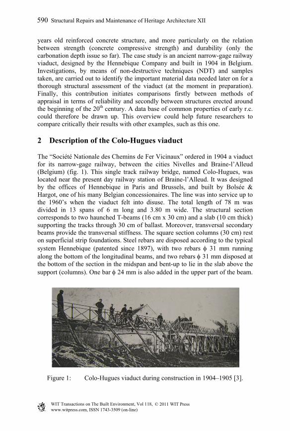
The “Société Nationale des Chemins de Fer Vicinaux” ordered in 1904 a viaduct for its narrow-gage railway, between the cities Nivelles and Braine-l’Alleud (Belgium) (fig. 1). This single track railway bridge, named Colo-Hugues, was located near the present day railway station of Braine-l’Alleud. It was designed by the offices of Hennebique in Paris and Brussels, and built by Bolsée & Hargot, one of his many Belgian concessionaires. The line was into service up to the 1960’s when the viaduct felt into disuse. The total length of 78 m was divided in 13 spans of 6 m long and 3.80 m wide. The structural section corresponds to two haunched T-beams (16 cm x 30 cm) and a slab (10 cm thick) supporting the tracks through 30 cm of ballast. Moreover, transversal secondary beams provide the transversal stiffness. The square section columns (30 cm) rest on superficial strip foundations. Steel rebars are disposed according to the typical system Hennebique (patented since 1897), with two rebars 31 mm running along the bottom of the longitudinal beams, and two rebars 31 mm disposed at the bottom of the section in the midspan and bent-up to lie in the slab above the support (columns). One bar 24 mm is also added in the upper part of the beam.
Figure 1: Colo-Hugues viaduct during construction in 1904–1905 [3].
590 Structural Repairs and Maintenance of Heritage Architecture XII
www.witpress.com, ISSN 1743-3509 (on-line) WIT Transactions on The Built Environment, Vol 118, © 2011 WIT Press
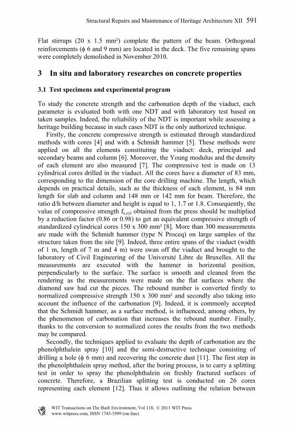
Flat stirrups (20 x 1.5 mm²) complete the pattern of the beam. Orthogonal reinforcements ( 6 and 9 mm) are located in the deck. The five remaining spans were completely demolished in November 2010.
3 In situ and laboratory researches on concrete properties
3.1 Test specimens and experimental program
To study the concrete strength and the carbonation depth of the viaduct, each parameter is evaluated both with one NDT and with laboratory test based on taken samples. Indeed, the reliability of the NDT is important while assessing a heritage building because in such cases NDT is the only authorized technique. Firstly, the concrete compressive strength is estimated through standardized methods with cores [4] and with a Schmidt hammer [5]. These methods were applied on all the elements constituting the viaduct: deck, principal and secondary beams and column [6]. Moreover, the Young modulus and the density of each element are also measured [7]. The compressive test is made on 13 cylindrical cores drilled in the viaduct. All the cores have a diameter of 83 mm, corresponding to the dimension of the core drilling machine. The length, which depends on practical details, such as the thickness of each element, is 84 mm length for slab and column and 148 mm or 142 mm for beam. Therefore, the ratio d/h between diameter and height is equal to 1, 1.7 or 1.8. Consequently, the value of compressive strength fc,cyl obtained from the press should be multiplied by a reduction factor (0.86 or 0.98) to get an equivalent compressive strength of standardized cylindrical cores 150 x 300 mm² [8]. More than 300 measurements are made with the Schmidt hammer (type N Proceq) on large samples of the structure taken from the site [9]. Indeed, three entire spans of the viaduct (width of 1 m, length of 7 m and 4 m) were swan off the viaduct and brought to the laboratory of Civil Engineering of the Université Libre de Bruxelles. All the measurements are executed with the hammer in horizontal position, perpendicularly to the surface. The surface is smooth and cleaned from the rendering as the measurements were made on the flat surfaces where the diamond saw had cut the pieces. The rebound number is converted firstly to normalized compressive strength 150 x 300 mm² and secondly also taking into account the influence of the carbonation [9]. Indeed, it is commonly accepted that the Schmidt hammer, as a surface method, is influenced, among others, by the phenomenon of carbonation that increases the rebound number. Finally, thanks to the conversion to normalized cores the results from the two methods may be compared. Secondly, the techniques applied to evaluate the depth of carbonation are the phenolphthalein spray [10] and the semi-destructive technique consisting of drilling a hole ( 6 mm) and recovering the concrete dust [11]. The first step in the phenolphthalein spray method, after the boring process, is to carry a splitting test in order to spray the phenolphthalein on freshly fractured surfaces of concrete. Therefore, a Brazilian splitting test is conducted on 26 cores representing each element [12]. Thus it allows outlining the relation between
Structural Repairs and Maintenance of Heritage Architecture XII 591
www.witpress.com, ISSN 1743-3509 (on-line) WIT Transactions on The Built Environment, Vol 118, © 2011 WIT Press
tensile strength and compressive strength for the associated concrete. Once more, testing a semi-destructive method in parallel with a well known invasive technique yields an opportunity to make a critical review of the NDT. Indeed, NDT receive generally a warm welcome from practitioners in the field of structural assessment even though limited studies have been carried out, as it is the case for the drilling hole technique for estimation of the carbonation front.
3.2 Assessment and discussion of the concrete compressive strength
In table 1, the mean and normalized values of the compressive strength are listed for each element. The conversion curves given by the producer is valid for any level of concrete strength and for a cylinder between 14 and 56 days old [9]. Therefore, a coefficient of reduction acting on the compressive strength is applied to simulate the carbonation influence. This factor takes into account the strength level and the age of the structure. Following the formula proposed by Kim et al. [13], this factor is equal to 0.63 for the column (rebound number = 33) and to 0.93 for the slab and beams (rebound number = 47 to 49).
Table 1: Results of the compressive tests, mean and normalized values for each element (150 x 300 mm²). A: on cylindrical core; B: with Schmidt Hammer; C: with Schmidt Hammer including carbonation correction; E: Young Modulus and the density.
Location A
fcm,cyl (MPa) B
fcm,cyl (MPa) C
fcm,cyl (MPa) E
(MPa) Density (kg/m³)
Slab 54,2 49,0 45,5 35 910 2372 Beam 33,3 45,3 41,5 28 357 2330
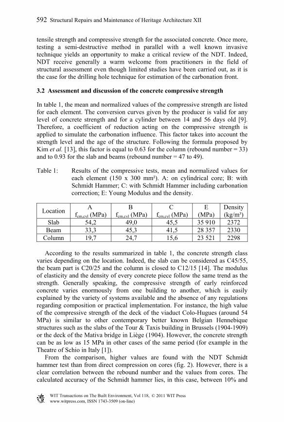
Column 19,7 24,7 15,6 23 521 2298 According to the results summarized in table 1, the concrete strength class varies depending on the location. Indeed, the slab can be considered as C45/55, the beam part is C20/25 and the column is closed to C12/15 [14]. The modulus of elasticity and the density of every concrete piece follow the same trend as the strength. Generally speaking, the compressive strength of early reinforced concrete varies enormously from one building to another, which is easily explained by the variety of systems available and the absence of any regulations regarding composition or practical implementation. For instance, the high value of the compressive strength of the deck of the viaduct Colo-Hugues (around 54 MPa) is similar to other contemporary better known Belgian Hennebique structures such as the slabs of the Tour & Taxis building in Brussels (1904-1909) or the deck of the Mativa bridge in Liège (1904). However, the concrete strength can be as low as 15 MPa in other cases of the same period (for example in the Theatre of Schio in Italy [1]). From the comparison, higher values are found with the NDT Schmidt hammer test than from direct compression on cores (fig. 2). However, there is a clear correlation between the rebound number and the values from cores. The calculated accuracy of the Schmidt hammer lies, in this case, between 10% and
592 Structural Repairs and Maintenance of Heritage Architecture XII
www.witpress.com, ISSN 1743-3509 (on-line) WIT Transactions on The Built Environment, Vol 118, © 2011 WIT Press
26%, which is a common precision for this technique [15]. Furthermore, the difference between extreme values in a same type of element is important and even higher when the measurement comes from the surface hardness method (fig. 2). Nevertheless, the compressive strength for the beam shows scattered results depending on the exact location of the cores in the viaduct. So far, there is no rational explanation, besides the possible change in concrete composition associated to a modification or a halt in the construction process. The first step for determination of the carbonation depth is a Brazilian splitting test (fig. 3). The ratio between tensile splitting strength and compressive
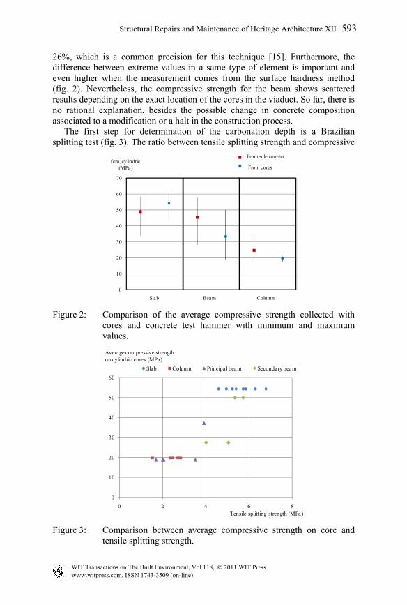
Figure 2: Comparison of the average compressive strength collected with cores and concrete test hammer with minimum and maximum values.
Figure 3: Comparison between average compressive strength on core and tensile splitting strength.
0
10
20
30
40
50
60
70
Slab Beam Column
fcm, cylindric (MPa)
From sclerometer
From cores
0
10
20
30
40
50
60
0 2 4 6 8Tensile splitting strength (MPa)
Slab Column Principal beam Secondary beam
Average compressive strength on cylindric cores (MPa)
Structural Repairs and Maintenance of Heritage Architecture XII 593
www.witpress.com, ISSN 1743-3509 (on-line) WIT Transactions on The Built Environment, Vol 118, © 2011 WIT Press
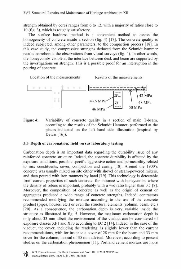
strength obtained by cores ranges from 6 to 12, with a majority of ratios close to 10 (fig. 3), which is roughly satisfactory. The surface hardness method is a convenient method to assess the homogeneity of concrete inside a section (fig. 4) [17]. The concrete quality is indeed subjected, among other parameters, to the compaction process [18]. In this case study, the compressive strengths deduced from the Schmidt hammer results corroborate the observations from visual surveys (fig. 4). In other words, the honeycombs visible at the interface between deck and beam are supported by the investigations on strength. This is a possible proof for an interruption in the pouring of concrete.
Figure 4: Variability of concrete quality in a section of main T-beam, according to the results of the Schmidt Hammer, performed at the places indicated on the left hand side illustration (inspired by Dewar [16]).
3.3 Depth of carbonation: field versus laboratory testing
Carbonation depth is an important data regarding the durability issue of any reinforced concrete structure. Indeed, the concrete durability is affected by the exposure conditions, possible specific aggressive action and permeability related to mix constituents, cover, compaction and curing [18]. Around the 1900’s concrete was usually mixed on site either with shovel or steam-powered mixers, and then poured with iron rammers by hand [19]. This technology is detectable from current properties of such concrete, for instance with honeycombs where the density of rebars is important, probably with a w/c ratio higher than 0.5 [8]. Moreover, the composition of concrete as well as the origin of cement or aggregates produced a wide range of concrete strengths. Indeed, contractors recommended modifying the mixture according to the use of the concrete product (pipes, houses, etc.) or even the structural elements (column, beam, etc.) [20]. As a consequence, the carbonation depth is very variable inside the structure as illustrated in fig. 5. However, the maximum carbonation depth is only about 33 mm albeit the environment of the viaduct can be considered of exposure classes XF1 and XF3 according to EC 2 [14]. Indeed, in the case of the viaduct, the cover, including the rendering, is slightly lower than the current recommendations, with for instance a cover of 28 mm for the beam and 33 mm cover for the column, instead of 35 mm advised. Moreover, according to present studies on the carbonation phenomenon [11], Portland cement mortars are more
48 MPa 50 MPa
43,5 MPa
46 MPa
42 MPa
Location of the measurements Results of the measurements
594 Structural Repairs and Maintenance of Heritage Architecture XII
www.witpress.com, ISSN 1743-3509 (on-line) WIT Transactions on The Built Environment, Vol 118, © 2011 WIT Press
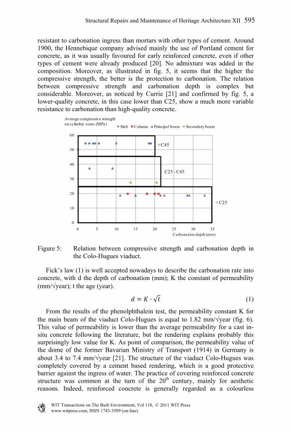
resistant to carbonation ingress than mortars with other types of cement. Around 1900, the Hennebique company advised mainly the use of Portland cement for concrete, as it was usually favoured for early reinforced concrete, even if other types of cement were already produced [20]. No admixture was added in the composition. Moreover, as illustrated in fig. 5, it seems that the higher the compressive strength, the better is the protection to carbonation. The relation between compressive strength and carbonation depth is complex but considerable. Moreover, as noticed by Currie [21] and confirmed by fig. 5, a lower-quality concrete, in this case lower than C25, show a much more variable resistance to carbonation than high-quality concrete.
Figure 5: Relation between compressive strength and carbonation depth in the Colo-Hugues viaduct.
Fick’s law (1) is well accepted nowadays to describe the carbonation rate into concrete, with d the depth of carbonation (mm); K the constant of permeability (mm/year); t the age (year).
· √ (1)
From the results of the phenolphthalein test, the permeability constant K for the main beam of the viaduct Colo-Hugues is equal to 1.82 mm/year (fig. 6). This value of permeability is lower than the average permeability for a cast in-situ concrete following the literature, but the rendering explains probably this surprisingly low value for K. As point of comparison, the permeability value of the dome of the former Bavarian Ministry of Transport (1914) in Germany is about 3.4 to 7.4 mm/year [21]. The structure of the viaduct Colo-Hugues was completely covered by a cement based rendering, which is a good protective barrier against the ingress of water. The practice of covering reinforced concrete structure was common at the turn of the 20th century, mainly for aesthetic reasons. Indeed, reinforced concrete is generally regarded as a colourless
0
10
20
30
40
50
60
0 5 10 15 20 25 30 35Carbonation depth (mm)
Slab Column Principal beam Secondary beam
< C25
C25 - C45
> C45
Average compressive strength on cylindric cores (MPa)
Structural Repairs and Maintenance of Heritage Architecture XII 595
www.witpress.com, ISSN 1743-3509 (on-line) WIT Transactions on The Built Environment, Vol 118, © 2011 WIT Press
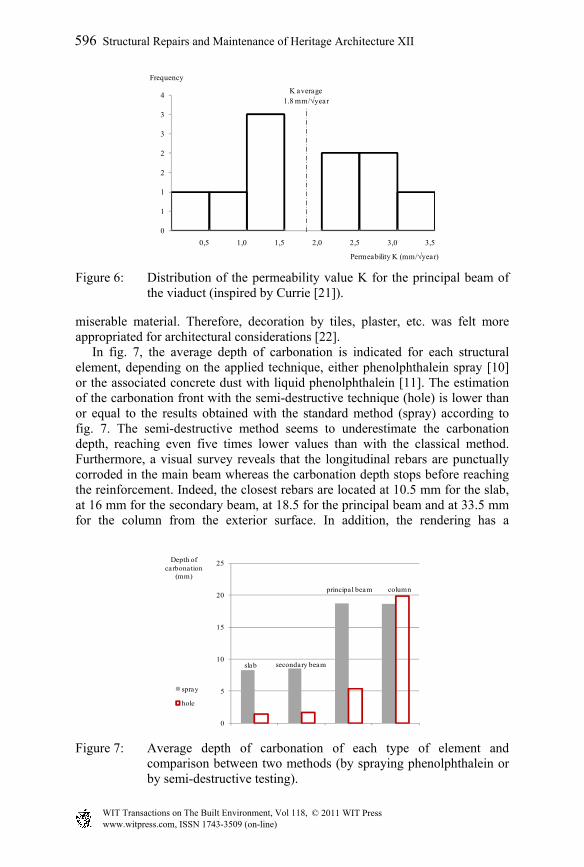
Figure 6: Distribution of the permeability value K for the principal beam of the viaduct (inspired by Currie [21]).
miserable material. Therefore, decoration by tiles, plaster, etc. was felt more appropriated for architectural considerations [22]. In fig. 7, the average depth of carbonation is indicated for each structural element, depending on the applied technique, either phenolphthalein spray [10] or the associated concrete dust with liquid phenolphthalein [11]. The estimation of the carbonation front with the semi-destructive technique (hole) is lower than or equal to the results obtained with the standard method (spray) according to fig. 7. The semi-destructive method seems to underestimate the carbonation depth, reaching even five times lower values than with the classical method. Furthermore, a visual survey reveals that the longitudinal rebars are punctually corroded in the main beam whereas the carbonation depth stops before reaching the reinforcement. Indeed, the closest rebars are located at 10.5 mm for the slab, at 16 mm for the secondary beam, at 18.5 for the principal beam and at 33.5 mm for the column from the exterior surface. In addition, the rendering has a
Figure 7: Average depth of carbonation of each type of element and comparison between two methods (by spraying phenolphthalein or by semi-destructive testing).
0
1
1
2
2
3
3
4
0,5 1,0 1,5 2,0 2,5 3,0 3,5
Frequency
Permeability K (mm/year)
K average1.8 mm/year
slab
column
secondary beam
principal beam
0
5
10
15
20
25Depth of carbonation
(mm)
spray
hole
596 Structural Repairs and Maintenance of Heritage Architecture XII
www.witpress.com, ISSN 1743-3509 (on-line) WIT Transactions on The Built Environment, Vol 118, © 2011 WIT Press
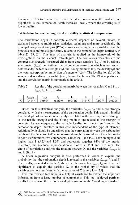
thickness of 0.5 to 1 mm. To explain the steel corrosion of the viaduct, one hypothesis is that carbonation depth increases locally where the covering is of lower quality.
3.4 Relation between strength and durability: statistical interpretation
The carbonation depth in concrete elements depends on several factors, as explained above. A multivariate statistical technique and more specifically the principal component analysis (PCA) allows evaluating which variables from the previous data are most significantly related to the carbonation depth (called X in table 2) [23, 24]. This type of analysis is applied in the framework of the investigations on the viaduct Colo-Hugues. The continuous variables are the compressive strength (measured either from cores samples (fcm,cyl) or by using a sclerometer (fcm,R) but without the carbonation correction which is not known beforehand), the tensile strength (fct), the Young modulus (E), the density (ρ) and the water absorption by immersion of concrete (Abs.). The localisation (L) of the sample test is a discrete variable (slab, beam of column). The PCA is performed and the correlation matrix is summarized in table 2.
Table 2: Results of the correlation matrix between the variables X and fcm,cyl, fcm,R, fct, L, E, ρ, Abs.
fcm,cyl fcm,R fct L E ρ Abs. X -0,4246 0,0594 -0,4649 -0,0146 -0,4477 -0,0273 0,0295
Based on this statistical analysis, the variables fcm,cyl, fct and E are strongly correlated with the measurement of the carbonation depth. This actually implies that the depth of carbonation is mainly correlated with the compressive strength as the tensile strength and the Young modulus are related to the strength of concrete. As a consequence, the variable localisation is not significant on the carbonation depth therefore in this case independent of the type of element. Additionally, it should be underlined that the correlation between the carbonation depth and the “uncorrected” compressive strength measured with the sclerometer is poor. Furthermore, two components, named PC1 and PC2, have an eigenvalue higher than 1 (5.25 and 1.37) and represents together 94% of the inertia. Therefore, the graphical representation is plotted in PC1 and PC2 axes. The circle of correlation confirms the relation between X and the variables fcm,cyl, fct and E (fig. 8). A linear regression analysis is also performed in order to explain the probability that the carbonation depth is related to the variables fcm,cyl, fct and E. The results, presented in table 3, show that the variables fcm,cyl, fct and E are all significant to explain the variable X, as the probability (P-value) that the variables are not significant with the variation of X is very low [25]. This multivariate technique is a helpful assistance to extract the important information from a large number of components. This tool achieved pertinent results for analysing the carbonation depth variation in the Colo-Hugues viaduct.
Structural Repairs and Maintenance of Heritage Architecture XII 597
www.witpress.com, ISSN 1743-3509 (on-line) WIT Transactions on The Built Environment, Vol 118, © 2011 WIT Press
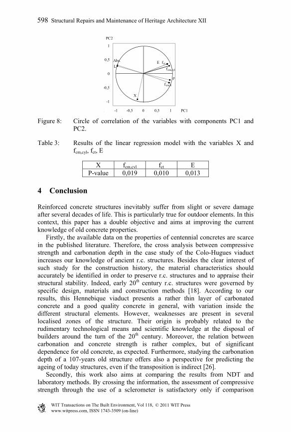
Figure 8: Circle of correlation of the variables with components PC1 and PC2.
Table 3: Results of the linear regression model with the variables X and fcm,cyl, fct, E
4 Conclusion
Reinforced concrete structures inevitably suffer from slight or severe damage after several decades of life. This is particularly true for outdoor elements. In this context, this paper has a double objective and aims at improving the current knowledge of old concrete properties. Firstly, the available data on the properties of centennial concretes are scarce in the published literature. Therefore, the cross analysis between compressive strength and carbonation depth in the case study of the Colo-Hugues viaduct increases our knowledge of ancient r.c. structures. Besides the clear interest of such study for the construction history, the material characteristics should accurately be identified in order to preserve r.c. structures and to appraise their structural stability. Indeed, early 20th century r.c. structures were governed by specific design, materials and construction methods [18]. According to our results, this Hennebique viaduct presents a rather thin layer of carbonated concrete and a good quality concrete in general, with variation inside the different structural elements. However, weaknesses are present in several localised zones of the structure. Their origin is probably related to the rudimentary technological means and scientific knowledge at the disposal of builders around the turn of the 20th century. Moreover, the relation between carbonation and concrete strength is rather complex, but of significant dependence for old concrete, as expected. Furthermore, studying the carbonation depth of a 107-years old structure offers also a perspective for predicting the ageing of today structures, even if the transposition is indirect [26]. Secondly, this work also aims at comparing the results from NDT and laboratory methods. By crossing the information, the assessment of compressive strength through the use of a sclerometer is satisfactory only if comparison
X
fcm,cyl
fcm,R
fctL
ρ
EAbs.
-1
-0,5
0
0,5
1
5 -1 -0,5 0 0,5 1 1,5
PC2
PC1
X fcm,cyl fct E P-value 0,019 0,010 0,013
598 Structural Repairs and Maintenance of Heritage Architecture XII
www.witpress.com, ISSN 1743-3509 (on-line) WIT Transactions on The Built Environment, Vol 118, © 2011 WIT Press
between cores and rebound number is possible. The estimation of the carbonation depth differs between the normalized technique and the semi-destructive method. So far, the in-situ evaluation seems to be less reliable than the classic phenolphthalein spray. However, the concrete quality of the viaduct is surprisingly satisfactory despite its great age. Finally, the durability issue is a global problem as summarized by Somerville: “The life of concrete structures in service depends not only on the production and placing of durable concrete, but also on proper design, detailing and construction methods, and on appropriate levels of maintenance” [18]. The combination of these parameters ensures the sustainability of a concrete structure such as the Colo-Hugues viaduct.
Acknowledgements
The authors are grateful to the CRICC-OCCN Laboratory and to Rajan Filomeno Coelho for their help in this study as well as the F.R.S.-FNRS for their financial support.
References
[1] Da Porto, F., Valluzzi, M. R., Srievanin, E. & Modena, C., Appraisal of two early twentieth century composite masonry-concrete structures: the Civic Theatre in Schio (Italy 1907) and Carraresi’s Castle in Padua (Italy, XIII century). Proc. of the Int. Association for Shell and Spatial Structures (IASS) Symposium. Evolution and Trends in Design, Analysis and Construction of Shell and Spatial Structures. eds. A. Domingo, & C. Lazaro, Valencia, pp. 698-709, 2009.
[2] Mezzina, M., Palmisano, F. & Uva, G., Reinforced Concrete Constructions at the Beginning of the 20th Century: Historical Review and Structural Assessment (Chapter 16). Materials, Technologies and Practice in Historic Heritage Structures, ed. M. B. Dan, R. Přikryl, & Á. Török, Springer Netherlands: Dordrecht, pp. 293-323, 2010.
[3] Cité de l’architecture et du patrimoine, Institut Français d’Architecture, Centre d’archives d’architecture du 20ème siècle, Fonds Bétons armés Hennebique, folders n° 076 Ifa 46/5 and n° 076 Ifa 1071/20, consultation in 2010.
[4] EN 12390-3, Testing hardened concrete: Part 3, compressive strength of test specimens, 2001.
[5] EN 12504:2, Testing concrete in structures. Non-destructive testing. Determination of rebound number, 2001.
[6] EN 13791, Assessment of in-situ compressive strength in structures and precast concrete components, pp. 1-27, 2007.
[7] NBN B 15-203, Concrete testing – Static module of elasticity with compression, 1990.
[8] Neville, A., Propriétés des bétons, Eyrolles: Paris, pp. 559-625, 2000.
Structural Repairs and Maintenance of Heritage Architecture XII 599
www.witpress.com, ISSN 1743-3509 (on-line) WIT Transactions on The Built Environment, Vol 118, © 2011 WIT Press
[9] Concrete Test Hammer. Original Schmidt Proceq N/NR - L/LR. User Manual. Switzerland, pp. 1-17, 2006.
[10] EN 14630, Products and systems for the protection and repair of concrete structures. Test methods. Determination of carbonation depth in hardened concrete by the phenolphthalein method, 2007.
[11] Pollet, V., Dooms, B. & Mosselmans, G., Corrosion des armatures induite par la carbonatation du béton: comment s’en prémunir? Les Dossiers du CSTC, 2(3), pp. 1-7, 2007.
[12] EN 12390-6, Testing hardened concrete: Part 6, tensile splitting strength of test specimens, 2000.
[13] Kim, J.-K., Kim, C.-Y., Yi, S.-T. & Lee, Y., Effect of carbonation on the rebound number and compressive strength of concrete. Cement and Concrete Composites, 31(2), pp. 139-144, 2009.
[14] EC2: Eurocode 2. Design of concrete structures, 2004-2006. [15] Malhotra, V. M. & Carino, N. J., Handbook on Nondestructive Testing of
Concrete (2e ed.). CRC Press, pp. 1.1-1.13, 2004. [16] Dewar, J.D., Testing concrete for durability (Part 1). Concrete, 19 (6), pp.
40-41, 1985. [17] Pucinotti, R. & De Lorenzo, R. A., In situ non-destructive testing : the steel
and concrete resistance assessment of ancient r/c structures. Proc. of the 11th Int. Conf. On Structural Studies, Repairs and Maintenance of Heritage Architecture, Malta, pp. 355-364, 2005.
[18] Somerville, G., The design life of concrete (with Discussion). The Structural Engineer, 64 (2), pp. 60-71, 64 (9), pp. 233-241, 1986.
[19] Loov, R., Reinforced concrete at the turn of the century. Concrete International, 13(12), pp. 67-73, 1991.
[20] Christophe, P., Le Béton Armé et ses Applications (2e éd.). Paris: C. Béranger, pp. 388-399, 1902.
[21] Currie, R. J., Carbonation depths in structural-quality concrete: an assessment of evidence from investigations of structures and from other sources, BRE 75, Building Research Establishment: Garston, Wartford, pp. 1-19, 1986.
[22] Cloquet, L., L’emploi du béton armé en architecture, Le Béton Armé, 11(17), pp.17-24, 1908.
[23] Abdi, H. & Williams, L. J., Principal component analysis. Wiley Interdisciplinary Reviews: Computational Statistics, 2(4), 2010.
[24] Harr, M., Reliability-Based Design in Civil Engineering. MacGraw-Hill Book Company, pp. 96-98, pp. 234-254, 1987.
[25] Schervish, M., P Values: What They Are and What They Are Not. The American Statistician, 50(3), pp. 203-206, 1996.
[26] Pade, C. & Guimaraes, M., The CO2 uptake of concrete in a 100 year perspective. Cement and Concrete Research, 37(9), pp. 1348-1356, 2007.
600 Structural Repairs and Maintenance of Heritage Architecture XII
www.witpress.com, ISSN 1743-3509 (on-line) WIT Transactions on The Built Environment, Vol 118, © 2011 WIT Press
Related Documents