Welcome message from author
This document is posted to help you gain knowledge. Please leave a comment to let me know what you think about it! Share it to your friends and learn new things together.
Transcript

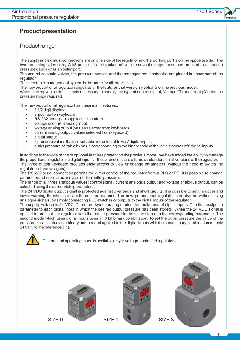
1700 Series
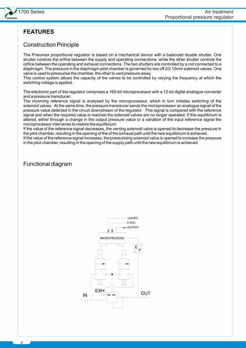
EP
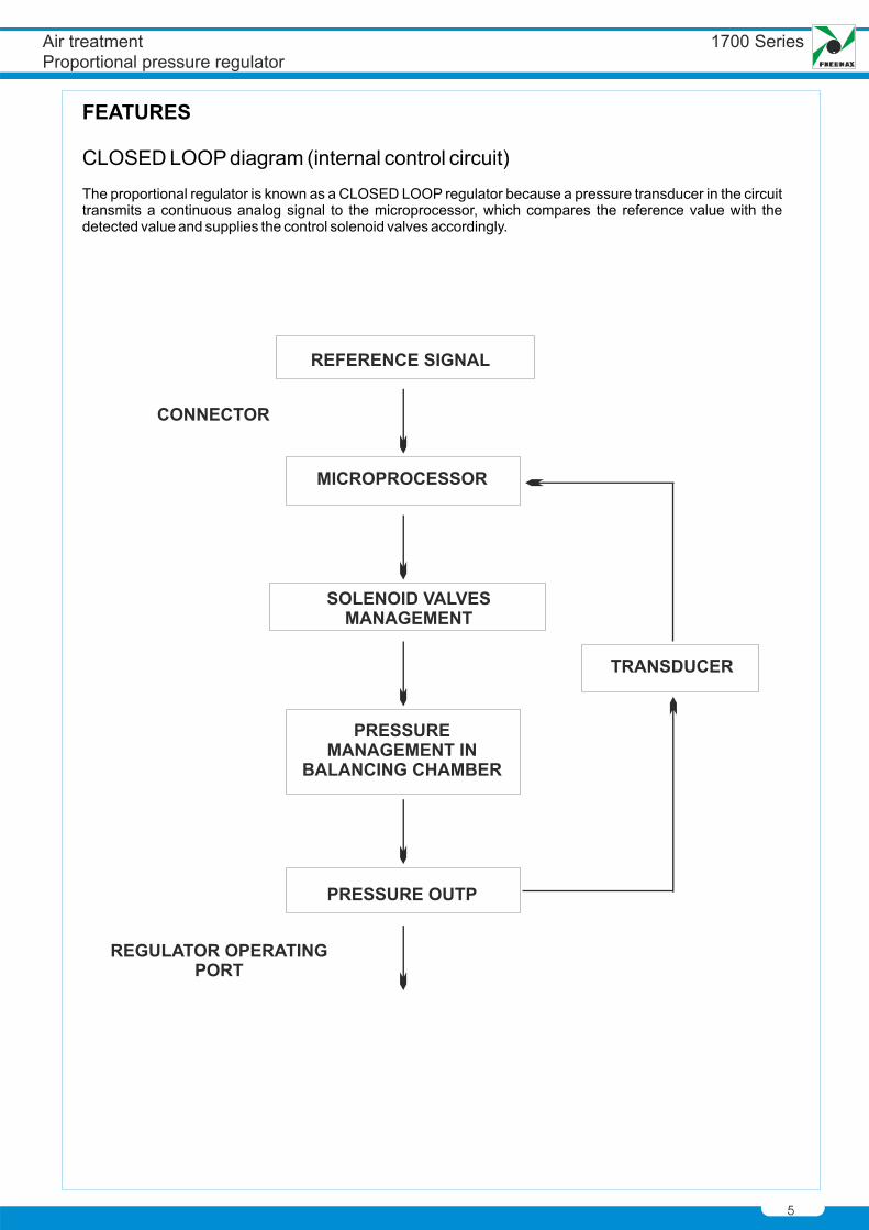
MICROPROCESS.
+24VDC
0 VDC
OUTPUT
IN OUTEXH
1700 Series
1700 Series
7
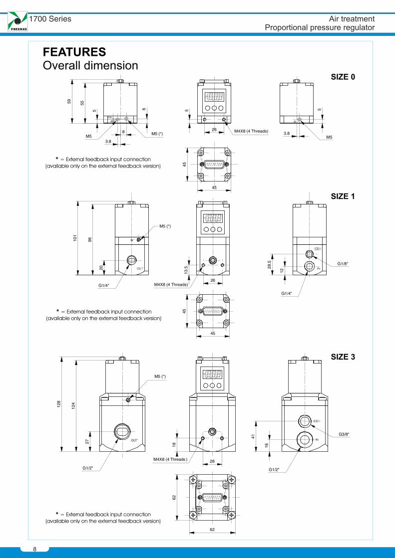
ø1,8
8
1700 Series
9
10
1155
11 88
99
1700 Series
11
Display features
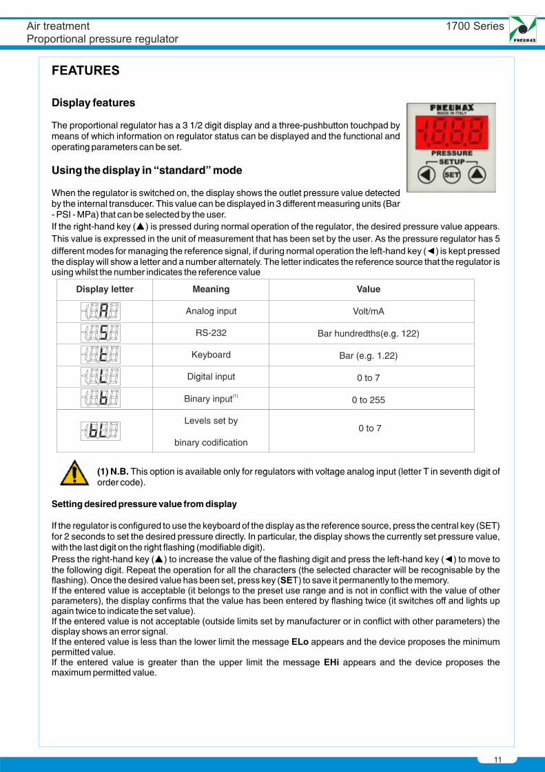
The proportional regulator has a 3 1/2 digit display and a three-pushbutton touchpad bymeans of which information on regulator status can be displayed and the functional andoperating parameters can be set.
Using the display in “standard” mode
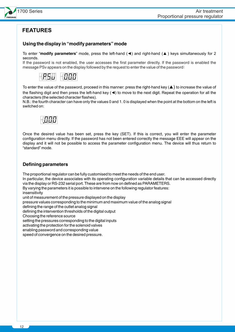
When the regulator is switched on, the display shows the outlet pressure value detectedby the internal transducer. This value can be displayed in 3 different measuring units (Bar- PSI - MPa) that can be selected by the user.If the right-hand key (
(1) N.B. This option is available only for regulators with voltage analog input (letter T in seventh digit oforder code).
Setting desired pressure value from display
If the regulator is configured to use the keyboard of the display as the reference source, press the central key (SET)for 2 seconds to set the desired pressure directly. In particular, the display shows the currently set pressure value,with the last digit on the right flashing (modifiable digit).Press the right-hand key (
Value
Volt/mA
Bar hundredths(e.g. 122)
Bar (e.g. 1.22)
0 to 7
0 to 255
Meaning
Analog input
RS-232
Keyboard
Digital input
(1)Binary input
Levels set by
binary codification
Display letter
0 to 7
12
Using the display in “modify parameters” mode
To enter “modify parameters” mode, press the left-hand (
To enter the value of the password, proceed in this manner: press the right-hand key () to move to the next digit.
Once the desired value has been set, press the key (SET). If this is correct, you will enter the parameterconfiguration menu directly. If the password has not been entered correctly the message EEE will appear on thedisplay and it will not be possible to access the parameter configuration menu. The device will thus return to“standard” mode.
Defining parameters
The proportional regulator can be fully customised to meet the needs of the end user.In particular, the device associates with its operating configuration variable details that can be accessed directlyvia the display or RS-232 serial port. These are from now on defined as PARAMETERS.By varying the parameters it is possible to intervene on the following regulator features:insensitivityunit of measurement of the pressure displayed on the displaypressure values corresponding to the minimum and maximum value of the analog signaldefining the range of the outlet analog signaldefining the intervention thresholds of the digital outputChoosing the reference sourcesetting the pressures corresponding to the digital inputsactivating the protection for the solenoid valvesenabling password and corresponding valuespeed of convergence on the desired pressure.
If the password is not enabled, the user accesses the first parameter directly. If the password is enabled themessage PSv appears on the display followed by the request to enter the value of the password
1700 Series
13
Warning
Whilst the regulator is in “modify parameters” mode outlet pressure is not adjusted, so it cannot beguaranteed that desired pressure corresponds to the outlet pressure.
Whilst the regulator is in “modify parameters” mode RS-232 communication is disabled.Press the two keys ( ) ( ) to leave “modify parameters” mode:
all the CONFIRMED parameters are saved to the permanent memory and are thus maintained evenafter switch-off.Analogue and digital output are not updated therefore it is not possible to ensure they are correct;
In order to leave “modify parameters” mode without saving any modified parameter (not evenconfirmed parameters) wait for two minutes to elapse without pressing any key. Alternatively, switch offthe regulator and switch it on again.
If the regulator is switched off whilst it is in “modify parameters” mode no modified parameter issaved to the permanent memory even if it has already been confirmed.
Modifying parametersOnce the user has entered the parameters configuration menu (with the previously described procedure), thedisplay is as follows:
P identifies the parameter selection mode whilst the number displayed on the right indicates the parameternumber.Press the right-hand key ( ) to change the parameter number from (P0) to (P22). Each time the key is pressed thenumber increases by 1; if the key is kept pressed the parameter number increases automatically.Once you have identified the parameter that you wish to display or modify, press the key (SET) to access it.After the key (SET) has been pressed the display shows the current value of the selected parameter and enables itto be modified. Depending on the type of parameter, 1 or more characters may be displayed.The procedure for modifying the values is the same as for entering the password: it is possible to modify just onecharacter at a time (the flashing character) by pressing the right-hand key ( ). On the other hand, if the left-handkey ( ) is pressed, the active character is changed (for those parameters that have more than one character).Once the value to be assigned to the parameter has been set, press the key (SET) to confirm the selection made.If the entered value is acceptable (it belongs to the preset use range and is not in conflict with the value of otherparameters) the display confirms that the value has been entered by flashing twice (it switches off and switches onagain twice to indicate the set value). A parameter that has been modified in this way is said to have beenCONFIRMED.When flashing stops the regulator returns to the parameter selection (it again displays the message “P X”, X beingthe last parameter to have been modified).If the entered value is not acceptable (outside the limits set by the manufacturer or in conflict with otherparameters) the display shows an error message.If the entered value is less than the lower limit the message ELo appears and the device proposes the minimumpermitted value.If the entered value is greater than the upper limit the message EHi appears and the device proposes themaximum permitted value.N.B.: the proposed values are not automatically confirmed. To confirm, press the key (SET).
By proceeding in this way (parameter selection, subsequent modification and confirmation) it is possible to modifythe value of all the parameters.Once all the values have been modified, in order to enable all the modified values to be saved and to return to thestandard operating mode, press the right-hand ( ) and left-hand ( ) keys simultaneously for about two seconds.
The regulator confirms the change of operating mode by showing this symbol on the display for about half asecond
14
List of parameters
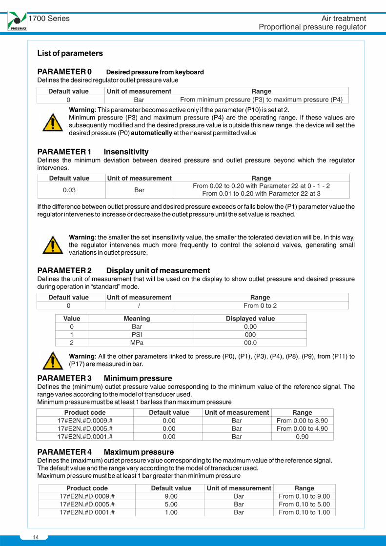
PARAMETER 0 Desired pressure from keyboardDefines the desired regulator outlet pressure value
Warning: This parameter becomes active only if the parameter (P10) is set at 2.Minimum pressure (P3) and maximum pressure (P4) are the operating range. If these values aresubsequently modified and the desired pressure value is outside this new range, the device will set thedesired pressure (P0) automatically at the nearest permitted value
PARAMETER 1 InsensitivityDefines the minimum deviation between desired pressure and outlet pressure beyond which the regulatorintervenes.
If the difference between outlet pressure and desired pressure exceeds or falls below the (P1) parameter value theregulator intervenes to increase or decrease the outlet pressure until the set value is reached.
Warning: the smaller the set insensitivity value, the smaller the tolerated deviation will be. In this way,the regulator intervenes much more frequently to control the solenoid valves, generating smallvariations in outlet pressure.
PARAMETER 2 Display unit of measurementDefines the unit of measurement that will be used on the display to show outlet pressure and desired pressureduring operation in “standard” mode.
Warning: All the other parameters linked to pressure (P0), (P1), (P3), (P4), (P8), (P9), from (P11) to (P17) are measured in bar.
PARAMETER 3 Minimum pressureDefines the (minimum) outlet pressure value corresponding to the minimum value of the reference signal. Therange varies according to the model of transducer used.Minimum pressure must be at least 1 bar less than maximum pressure
PARAMETER 4 Maximum pressureDefines the (maximum) outlet pressure value corresponding to the maximum value of the reference signal.The default value and the range vary according to the model of transducer used.Maximum pressure must be at least 1 bar greater than minimum pressure
Default value0
Unit of measurement/
RangeFrom 0 to 2
Value012
MeaningBarPSIMPa
Displayed value0.0000000.0
Default value
0.03
Unit of measurement
Bar
RangeFrom 0.02 to 0.20 with Parameter 22 at 0 - 1 - 2
From 0.01 to 0.20 with Parameter 22 at 3
Default value0
Unit of measurementBar
RangeFrom minimum pressure (P3) to maximum pressure (P4)
Product code17#E2N.#D.0009.#17#E2N.#D.0005.#17#E2N.#D.0001.#
Default value0.000.000.00
Unit of measurementBarBarBar
RangeFrom 0.00 to 8.90From 0.00 to 4.90
0.90
Product code17#E2N.#D.0009.#17#E2N.#D.0005.#17#E2N.#D.0001.#
9.005.001.00
Default valueBarBarBar
Unit of measurement RangeFrom 0.10 to 9.00From 0.10 to 5.00From 0.10 to 1.00
1700 Series
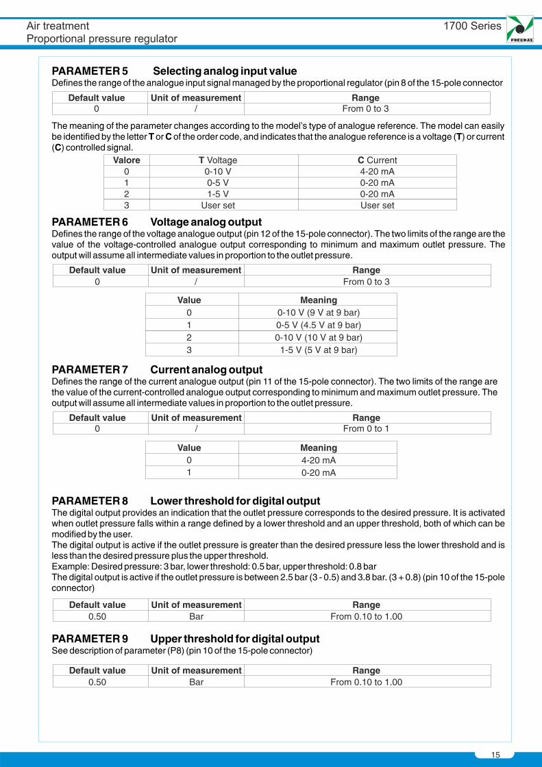
PARAMETER 5 Selecting analog input valueDefines the range of the analogue input signal managed by the proportional regulator (pin 8 of the 15-pole connector
The meaning of the parameter changes according to the model's type of analogue reference. The model can easilybe identified by the letter T or C of the order code, and indicates that the analogue reference is a voltage (T) or current(C) controlled signal.
15
Default value0
Unit of measurement/
RangeFrom 0 to 3
PARAMETER 6 Voltage analog outputDefines the range of the voltage analogue output (pin 12 of the 15-pole connector). The two limits of the range are thevalue of the voltage-controlled analogue output corresponding to minimum and maximum outlet pressure. Theoutput will assume all intermediate values in proportion to the outlet pressure.
Default value0
Unit of measurement/
RangeFrom 0 to 3
PARAMETER 7 Current analog outputDefines the range of the current analogue output (pin 11 of the 15-pole connector). The two limits of the range arethe value of the current-controlled analogue output corresponding to minimum and maximum outlet pressure. Theoutput will assume all intermediate values in proportion to the outlet pressure.
Value01
Meaning4-20 mA0-20 mA
Default value0
Unit of measurement/
RangeFrom 0 to 1
PARAMETER 8 Lower threshold for digital outputThe digital output provides an indication that the outlet pressure corresponds to the desired pressure. It is activatedwhen outlet pressure falls within a range defined by a lower threshold and an upper threshold, both of which can bemodified by the user.The digital output is active if the outlet pressure is greater than the desired pressure less the lower threshold and isless than the desired pressure plus the upper threshold.Example: Desired pressure: 3 bar, lower threshold: 0.5 bar, upper threshold: 0.8 barThe digital output is active if the outlet pressure is between 2.5 bar (3 - 0.5) and 3.8 bar. (3 + 0.8) (pin 10 of the 15-poleconnector)
Default value0.50
Unit of measurementBar
RangeFrom 0.10 to 1.00
PARAMETER 9 Upper threshold for digital outputSee description of parameter (P8) (pin 10 of the 15-pole connector)
Default v0.50
alue Unit of measurementBar
RangeFrom 0.10 to 1.00
Valore0123
T Voltage0-10 V0-5 V1-5 V
User set
C Current4-20 mA0-20 mA0-20 mAUser set
Value0123
Meaning0-10 V (9 V at 9 bar)0-5 V (4.5 V at 9 bar)0-10 V (10 V at 9 bar)
1-5 V (5 V at 9 bar)
16
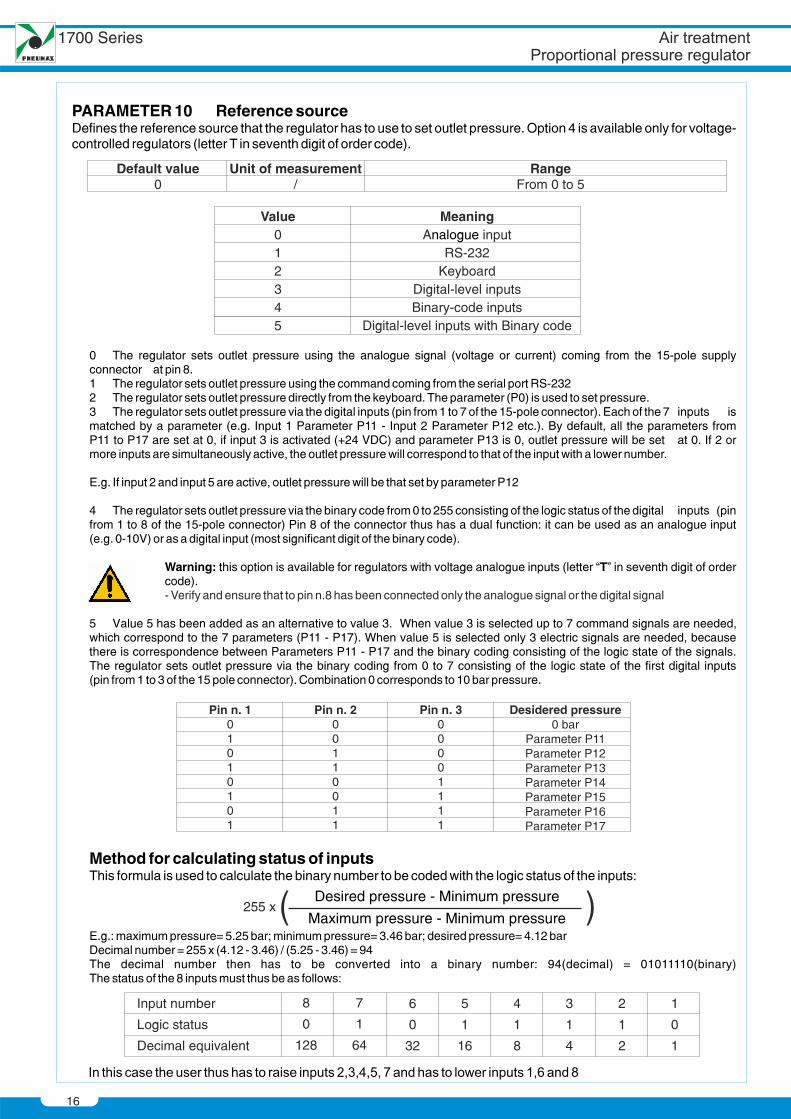
PARAMETER Reference sourceDefines the reference source that the regulator has to use to set outlet pressure. Option 4 is available only for voltage-controlled regulators (letter T in seventh digit of order code).
10
0 The regulator sets outlet pressure using the analogue signal (voltage or current) coming from the 15-pole supplyconnector at pin 8.1 The regulator sets outlet pressure using the command coming from the serial port RS-2322 The regulator sets outlet pressure directly from the keyboard. The parameter (P0) is used to set pressure.3 The regulator sets outlet pressure via the digital inputs (pin from 1 to 7 of the 15-pole connector). Each of the 7 inputs ismatched by a parameter (e.g. Input 1 Parameter P11 - Input 2 Parameter P12 etc.). By default, all the parameters fromP11 to P17 are set at 0, if input 3 is activated (+24 VDC) and parameter P13 is 0, outlet pressure will be set at 0. If 2 ormore inputs are simultaneously active, the outlet pressure will correspond to that of the input with a lower number.
E.g. If input 2 and input 5 are active, outlet pressure will be that set by parameter P12
4 The regulator sets outlet pressure via the binary code from 0 to 255 consisting of the logic status of the digital inputs (pinfrom 1 to 8 of the 15-pole connector) Pin 8 of the connector thus has a dual function: it can be used as an analogue input(e.g. 0-10V) or as a digital input (most significant digit of the binary code).
Warning: this option is available for regulators with voltage analogue inputs (letter “T” in seventh digit of ordercode).
5 Value 5 has been added as an alternative to value 3. When value 3 is selected up to 7 command signals are needed, which correspond to the 7 parameters (P11 - P17). When value 5 is selected only 3 electric signals are needed, becausethere is correspondence between Parameters P11 - P17 and the binary coding consisting of the logic state of the signals.The regulator sets outlet pressure via the binary coding from 0 to 7 consisting of the logic state of the first digital inputs(pin from 1 to 3 of the 15 pole connector). Combination 0 corresponds to 10 bar pressure.
Method for calculating status of inputsThis formula is used to calculate the binary number to be coded with the logic status of the inputs:
E.g.: maximum pressure= 5.25 bar; minimum pressure= 3.46 bar; desired pressure= 4.12 barDecimal number = 255 x (4.12 - 3.46) / (5.25 - 3.46) = 94The decimal number then has to be converted into a binary number: 94(decimal) = 01011110(binary)The status of the 8 inputs must thus be as follows:
- Verify and ensure that to pin n.8 has been connected only the analogue signal or the digital signal
Input number
Logic status
Decimal equivalent
8
0
128
7
1
64
6
0
32
5
1
16
4
1
8
3
1
4
2
1
2
1
0
1
Default v u0
al e Unit of measurement/
RangeFrom 0 to 5
1700 Series
Value012345
MeaningA input
RS-232Keyboard
Digital-level inputsBinary-code inputs
Digital-level inputs with Binary code
nalogue
Pin n. 101010101
Pin n. 200110011
Pin n. 300001111
Desidered pressure0 bar
Parameter P11Parameter P12Parameter P13Parameter P14Parameter P15Parameter P16Parameter P17
Desired pressure - Minimum pressure
Maximum pressure - Minimum pressure255 x
17
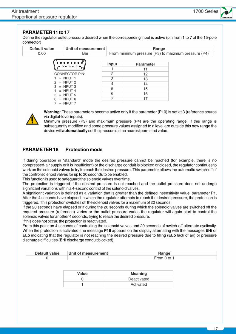
Value01
MeaningDeactivated
Activated
Default value0
Unit of measurement/
RangeFrom 0 to 1
PARAMETER 11 to 17Define the regulator outlet pressure desired when the corresponding input is active (pin from 1 to 7 of the 15-poleconnector)
Default value0.00
Unit of measurementBar
RangeFrom minimum pressure (P3) to maximum pressure (P4)
Input1234567
Parameter11121314151617
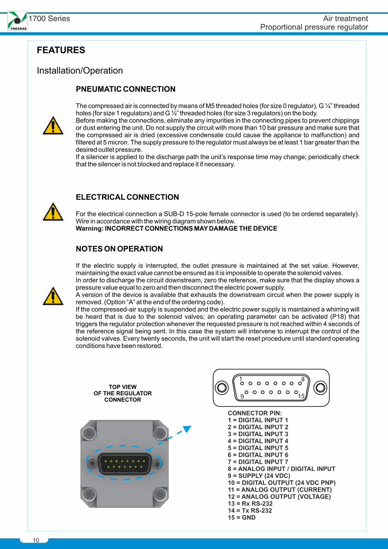
CONNECTOR PIN1 = INPUT 12 = INPUT 23 = INPUT 34 = INPUT 45 = INPUT 56 = INPUT 67 = INPUT 7
Warning: These parameters become active only if the parameter (P10) is set at 3 (reference sourcevia digital-level inputs).Minimum pressure (P3) and maximum pressure (P4) are the operating range. If this range issubsequently modified and some pressure values assigned to a level are outside this new range thedevice will automatically set the pressure at the nearest permitted value.
PARAMETER 18 Protection mode
If during operation in “standard” mode the desired pressure cannot be reached (for example, there is nocompressed-air supply or it is insufficient) or the discharge conduit is blocked or closed, the regulator continues towork on the solenoid valves to try to reach the desired pressure. This parameter allows the automatic switch-off ofthe control solenoid valves for up to 20 seconds to be enabled.This function is used to safeguard the solenoid valves over time.The protection is triggered if the desired pressure is not reached and the outlet pressure does not undergosignificant variations within a 4-second control of the solenoid valves.A significant variation is defined as a variation that is greater than the defined insensitivity value, parameter P1. After the 4 seconds have elapsed in which the regulator attempts to reach the desired pressure, the protection istriggered. This protection switches off the solenoid valves for a maximum of 20 seconds.If the 20 seconds have elapsed or if during the 20 seconds during which the solenoid valves are switched off therequired pressure (reference) varies or the outlet pressure varies the regulator will again start to control thesolenoid valves for another 4 seconds, trying to reach the desired pressure.If this does not occur, the protection is reactivated.From this point on 4 seconds of controlling the solenoid valves and 20 seconds of switch-off alternate cyclically.When the protection is activated, the message P18 appears on the display alternating with the messages EHi orELo indicating that the regulator is not reaching the desired pressure due to filling (ELo lack of air) or pressuredischarge difficulties (EHi discharge conduit blocked).
18
Default value0
Unit of measurement/
RangeFrom 0 to 1
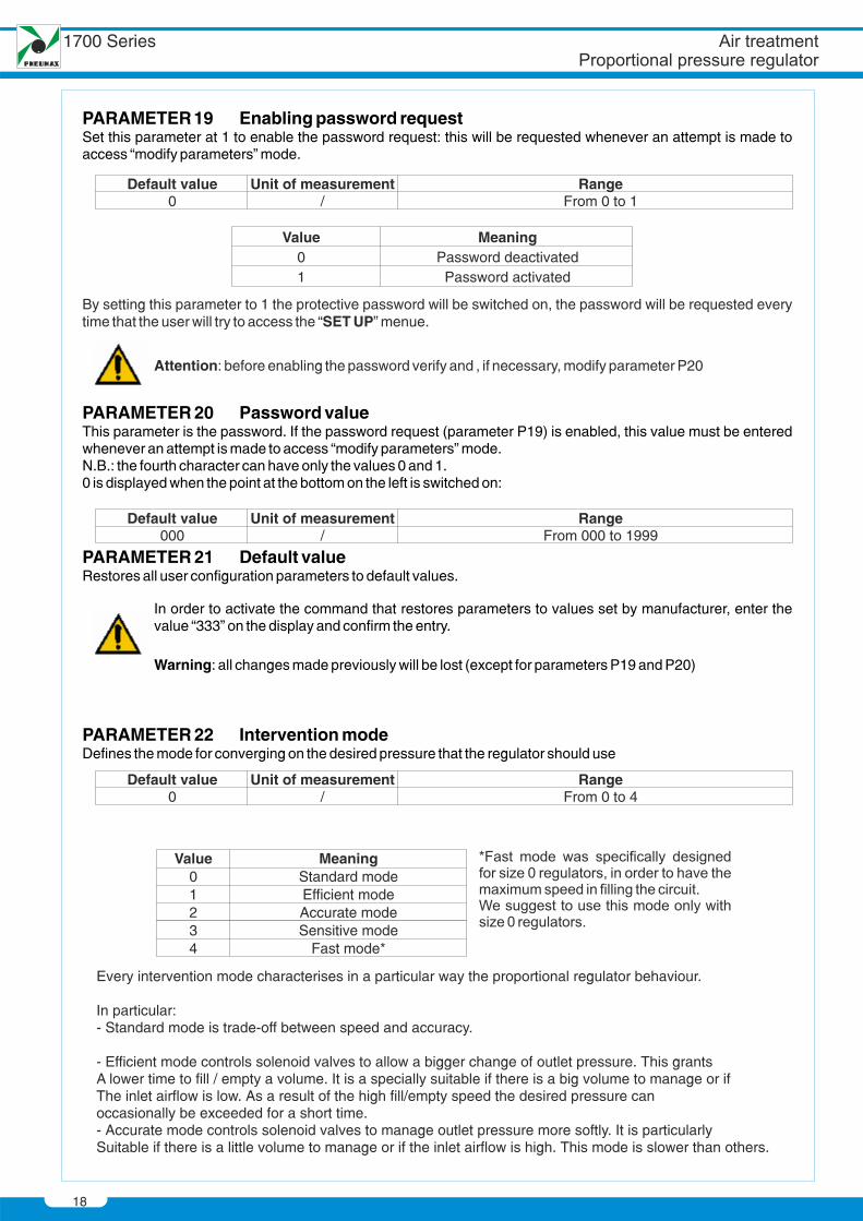
PARAMETER19 Enabling password requestSet this parameter at 1 to enable the password request: this will be requested whenever an attempt is made toaccess “modify parameters” mode.
Value01
MeaningPassword deactivated
Password activated
PARAMETER 20 Password valueThis parameter is the password. If the password request (parameter P19) is enabled, this value must be enteredwhenever an attempt is made to access “modify parameters” mode.N.B.: the fourth character can have only the values 0 and 1.0 is displayed when the point at the bottom on the left is switched on:
Default value000
Unit of measurement/
RangeFrom 000 to 1999
PARAMETER 22 Intervention modeDefines the mode for converging on the desired pressure that the regulator should use
PARAMETER 21 Default valueRestores all user configuration parameters to default values.
In order to activate the command that restores parameters to values set by manufacturer, enter thevalue “333” on the display and confirm the entry.
Warning: all changes made previously will be lost (except for parameters P19 and P20)
Default value0
Unit of measurement/
RangeFrom 0 to 4
1700 Series
Attention: before enabling the password verify and , if necessary, modify parameter P20
Every intervention mode characterises in a particular way the proportional regulator behaviour.
In particular:- Standard mode is trade-off between speed and accuracy.
- Efficient mode controls solenoid valves to allow a bigger change of outlet pressure. This grantsA lower time to fill / empty a volume. It is a specially suitable if there is a big volume to manage or ifThe inlet airflow is low. As a result of the high fill/empty speed the desired pressure canoccasionally be exceeded for a short time.- Accurate mode controls solenoid valves to manage outlet pressure more softly. It is particularlySuitable if there is a little volume to manage or if the inlet airflow is high. This mode is slower than others.
By setting this parameter to 1 the protective password will be switched on, the password will be requested everytime that the user will try to access the “SET UP” menue.
Value01234
MeaningStandard modeEfficient modeAccurate modeSensitive mode
Fast mode*
19
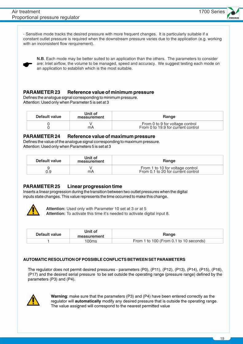
The regulator does not permit desired pressures - parameters (P0), (P11), (P12), (P13), (P14), (P15), (P16), (P17) and the desired serial pressure to be set outside the operating range (pressure range) defined by the parameters (P3) and (P4).
AUTOMATIC RESOLUTION OF POSSIBLE CONFLICTS BETWEEN SET PARAMETERS
Warning: make sure that the parameters (P3) and (P4) have been entered correctly as the regulator will automatically modify any desired pressure that is outside the operating range.The value assigned will correspond to the nearest permitted value
- Sensitive mode tracks the desired pressure with more frequent changes. It is particularly suitable if a constant outlet pressure is required when the downstream pressure varies due to the application (e.g. working with an inconsistent flow rerquirement).
N.B. Each mode may be better suited to an application than the others. The parameters to consider are: Inlet airflow, the volume to be managed, speed and accuracy. We suggest testing each mode on an application to establish which is the most suitable.
PARAMETER 23 Reference value of minimum pressureDefines the analogue signal corresponding to minimum pressure.Attention: Used only when Parameter 5 is set at 3
PARAMETER 25 Linear progression timeInserts a linear progression during the transition between two outlet pressures when the digitalinputs state changes. This value represents the time occurred to make this change.
PARAMETER 24 Reference value of maximum pressureDefines the value of the analogue signal corresponding to maximum pressure.Attention: Used only when Parameters 5 is set at 3
Default value
1
Unit ofmeasurement
100ms
Range
From 1 to 100 (From 0.1 to 10 seconds)
Default value
00
Unit ofmeasurement
mAV
Range
From 0 to 9 for voltage controlFrom 0 to 19.9 for current control
Default value
90.9
Unit ofmeasurement
mAV
Range
From 1 to 10 for voltage controlFrom 0.1 to 20 for current control
Attention: Used only with Parameter 10 set at 3 or at 5Attention: To activate this time it’s needed to activate digital input 8.
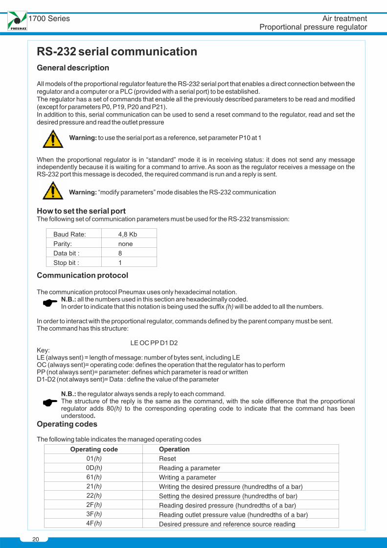
General description
All models of the proportional regulator feature the RS-232 serial port that enables a direct connection between theregulator and a computer or a PLC (provided with a serial port) to be established.The regulator has a set of commands that enable all the previously described parameters to be read and modified(except for parameters P0, P19, P20 and P21).In addition to this, serial communication can be used to send a reset command to the regulator, read and set thedesired pressure and read the outlet pressure
Warning: to use the serial port as a reference, set parameter P10 at 1
OperationResetReading a parameterWriting a parameterWriting the desired pressure (hundredths of a bar)Setting the desired pressure (hundredths of bar)Reading desired pressure (hundredths of a bar)Reading outlet pressure value (hundredths of a bar)Desired pressure and reference source reading
20
1700 Series
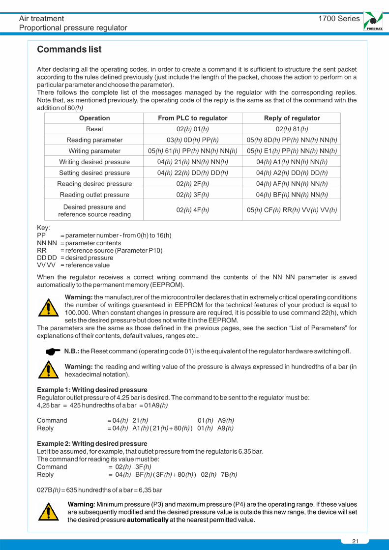
Commands list
After declaring all the operating codes, in order to create a command it is sufficient to structure the sent packetaccording to the rules defined previously (just include the length of the packet, choose the action to perform on aparticular parameter and choose the parameter).There follows the complete list of the messages managed by the regulator with the corresponding replies.Note that, as mentioned previously, the operating code of the reply is the same as that of the command with theaddition of 80(h)
Key:PP = parameter number - from 0(h) to 16(h)NN NN = parameter contents
When the regulator receives a correct writing command the contents of the NN NN parameter is savedautomatically to the permanent memory (EEPROM).
Warning: the manufacturer of the microcontroller declares that in extremely critical operating conditionsthe number of writings guaranteed in EEPROM for the technical features of your product is equal to100.000. When constant changes in pressure are required, it is possible to use command 22(h), whichsets the desired pressure but does not write it in the EEPROM.
The parameters are the same as those defined in the previous pages, see the section “List of Parameters” forexplanations of their contents, default values, ranges etc..
N.B.: the Reset command (operating code 01) is the equivalent of the regulator hardware switching off.
Warning: the reading and writing value of the pressure is always expressed in hundredths of a bar (inhexadecimal notation).
Example 1: Writing desired pressureRegulator outlet pressure of 4.25 bar is desired. The command to be sent to the regulator must be:4,25 bar = 425 hundredths of a bar = 01A9(h)
Command = 04(h) 21(h) 01(h) A9(h)Reply = 04(h) A1(h) ( 21(h)+ 80(h) ) 01(h) A9(h)
Example 2: Writing desired pressureLet it be assumed, for example, that outlet pressure from the regulator is 6.35 bar.The command for reading its value must be:Command = 02(h) 3F(h)Reply = 04(h) BF(h) ( 3F(h)+ 80(h) ) 02(h) 7B(h)
027B(h)= 635 hundredths of a bar = 6,35 bar
Warning: Minimum pressure (P3) and maximum pressure (P4) are the operating range. If these valuesare subsequently modified and the desired pressure value is outside this new range, the device will setthe desired pressure automatically at the nearest permitted value.
21
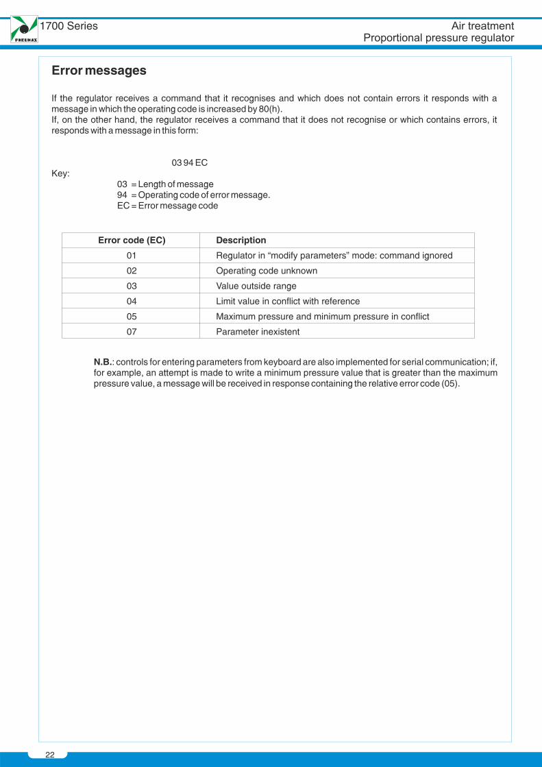
Error messages
If the regulator receives a command that it recognises and which does not contain errors it responds with amessage in which the operating code is increased by 80(h).If, on the other hand, the regulator receives a command that it does not recognise or which contains errors, itresponds with a message in this form:
03 94 ECKey:
03 = Length of message94 = Operating code of error message.EC = Error message code
Error code (EC)
01
02
03
04
05
07
Description
Regulator in “modify parameters” mode: command ignored
Operating code unknown
Value outside range
Limit value in conflict with reference
Maximum pressure and minimum pressure in conflict
Parameter inexistent
N.B.: controls for entering parameters from keyboard are also implemented for serial communication; if,for example, an attempt is made to write a minimum pressure value that is greater than the maximumpressure value, a message will be received in response containing the relative error code (05).
22
1700 Series
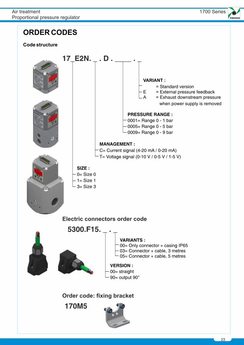
17_E2N. _ . D . ____ . _
MANAGEMENT :CT= Voltage signal (0-10 V / 0-5 V / 1-5 V)
= Current signal (4-20 mA / 0-20 mA)
PRESSURE RANGE :
0005= Range 0 - 5 bar0009= Range 0 - 9 bar
0001= Range 0 - 1 bar
5300.F15. _ . _
VERSION :0090= output 90
= straight
VARIANTS :
03= Connector + cable, 3 metres05= Connector + cable, 5 metres
00= Only connector + casing IP65
170M5
SIZE :01= Size 13= Size 3
= Size 0
23
External pressure feedbackExhaust downstream pressure
when power supply is removed
Standard version
24
1700 Series

Related Documents