COLLEGE PHYSICS Chapter # Chapter Title PowerPoint Image Slideshow COLLEGE PHYSICS Chapter 19 ELECTRIC POTENTIAL AND ELECTRIC FIELD PowerPoint Image Slideshow

COLLEGE PHYSICS Chapter 19 ELECTRIC POTENTIAL AND ELECTRIC FIELD PowerPoint Image Slideshow.
Jan 03, 2016
Welcome message from author
This document is posted to help you gain knowledge. Please leave a comment to let me know what you think about it! Share it to your friends and learn new things together.
Transcript
COLLEGE PHYSICSChapter 19 ELECTRIC POTENTIAL AND ELECTRIC FIELD
PowerPoint Image Slideshow

FIGURE 19.1
Automated external defibrillator unit (AED) (credit: U.S. Defense Department photo/Tech. Sgt. Suzanne M. Day)
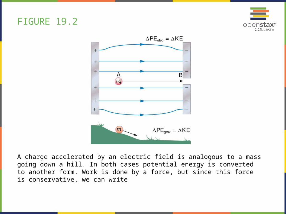
FIGURE 19.2
A charge accelerated by an electric field is analogous to a mass going down a hill. In both cases potential energy is converted to another form. Work is done by a force, but since this force is conservative, we can write
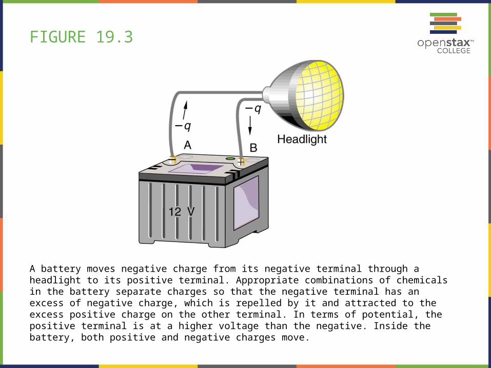
FIGURE 19.3
A battery moves negative charge from its negative terminal through a headlight to its positive terminal. Appropriate combinations of chemicals in the battery separate charges so that the negative terminal has an excess of negative charge, which is repelled by it and attracted to the excess positive charge on the other terminal. In terms of potential, the positive terminal is at a higher voltage than the negative. Inside the battery, both positive and negative charges move.
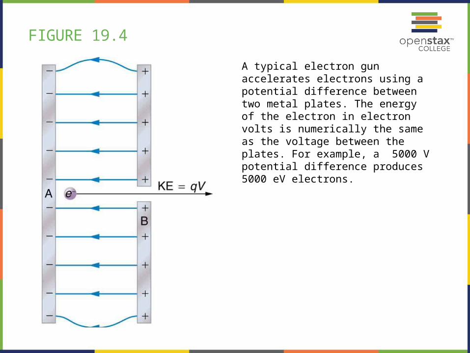
FIGURE 19.4
A typical electron gun accelerates electrons using a potential difference between two metal plates. The energy of the electron in electron volts is numerically the same as the voltage between the plates. For example, a 5000 V potential difference produces 5000 eV electrons.
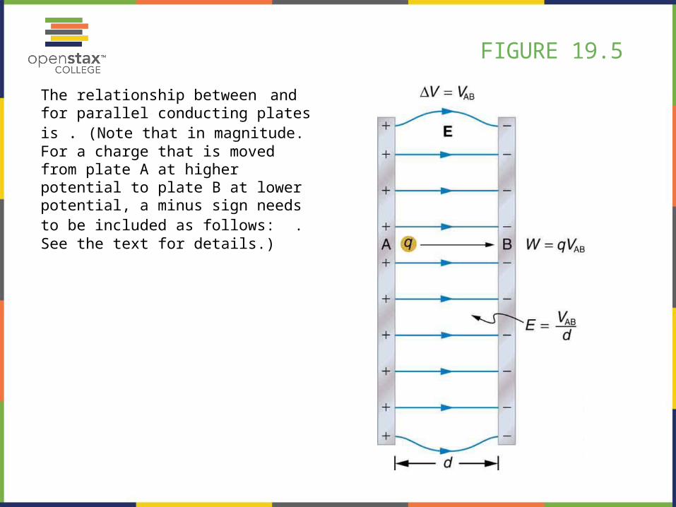
FIGURE 19.5
The relationship between and for parallel conducting plates is . (Note that in magnitude. For a charge that is moved from plate A at higher potential to plate B at lower potential, a minus sign needs to be included as follows: . See the text for details.)
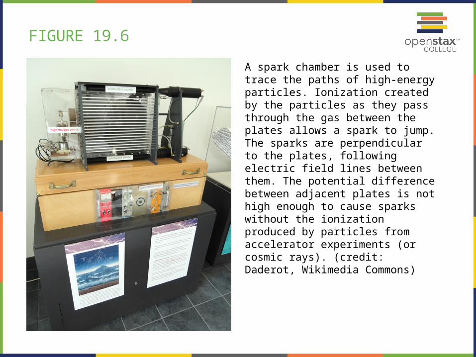
FIGURE 19.6
A spark chamber is used to trace the paths of high-energy particles. Ionization created by the particles as they pass through the gas between the plates allows a spark to jump. The sparks are perpendicular to the plates, following electric field lines between them. The potential difference between adjacent plates is not high enough to cause sparks without the ionization produced by particles from accelerator experiments (or cosmic rays). (credit: Daderot, Wikimedia Commons)
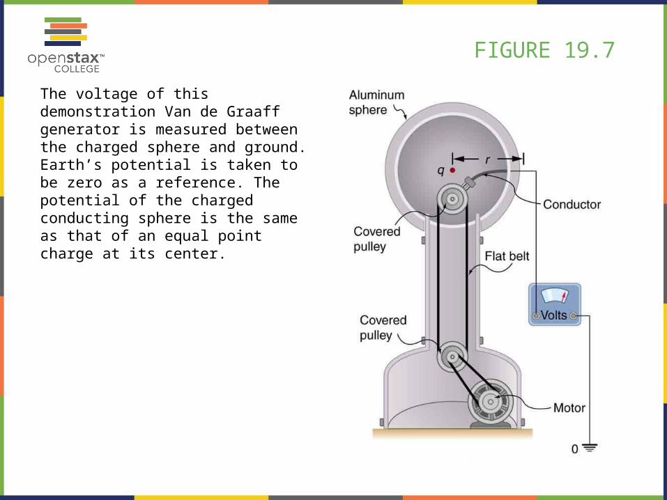
FIGURE 19.7
The voltage of this demonstration Van de Graaff generator is measured between the charged sphere and ground. Earth’s potential is taken to be zero as a reference. The potential of the charged conducting sphere is the same as that of an equal point charge at its center.
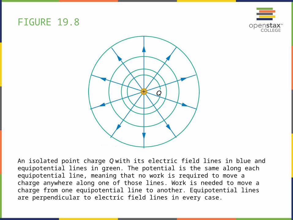
FIGURE 19.8
An isolated point charge Q with its electric field lines in blue and equipotential lines in green. The potential is the same along each equipotential line, meaning that no work is required to move a charge anywhere along one of those lines. Work is needed to move a charge from one equipotential line to another. Equipotential lines are perpendicular to electric field lines in every case.
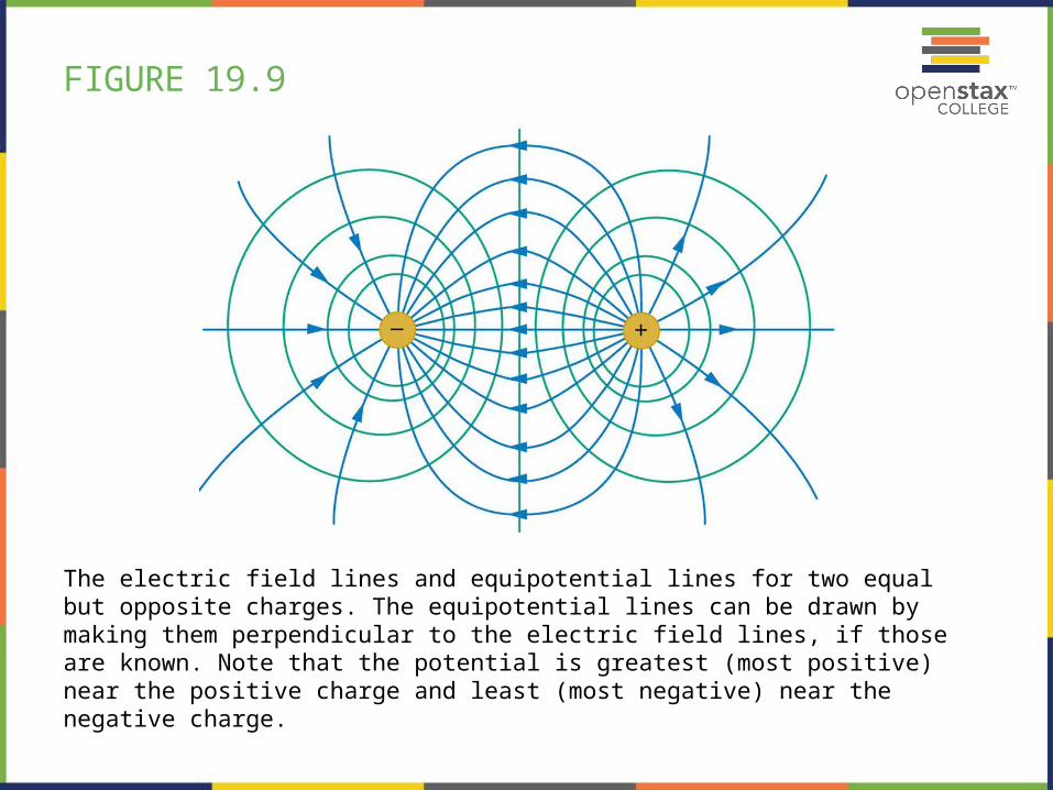
FIGURE 19.9
The electric field lines and equipotential lines for two equal but opposite charges. The equipotential lines can be drawn by making them perpendicular to the electric field lines, if those are known. Note that the potential is greatest (most positive) near the positive charge and least (most negative) near the negative charge.
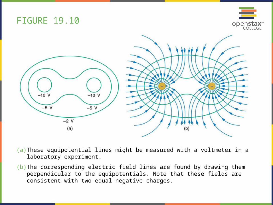
FIGURE 19.10
(a) These equipotential lines might be measured with a voltmeter in a laboratory experiment.
(b) The corresponding electric field lines are found by drawing them perpendicular to the equipotentials. Note that these fields are consistent with two equal negative charges.
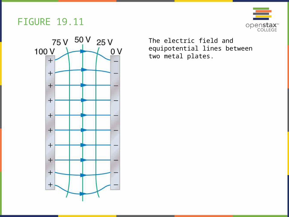
FIGURE 19.11
The electric field and equipotential lines between two metal plates.
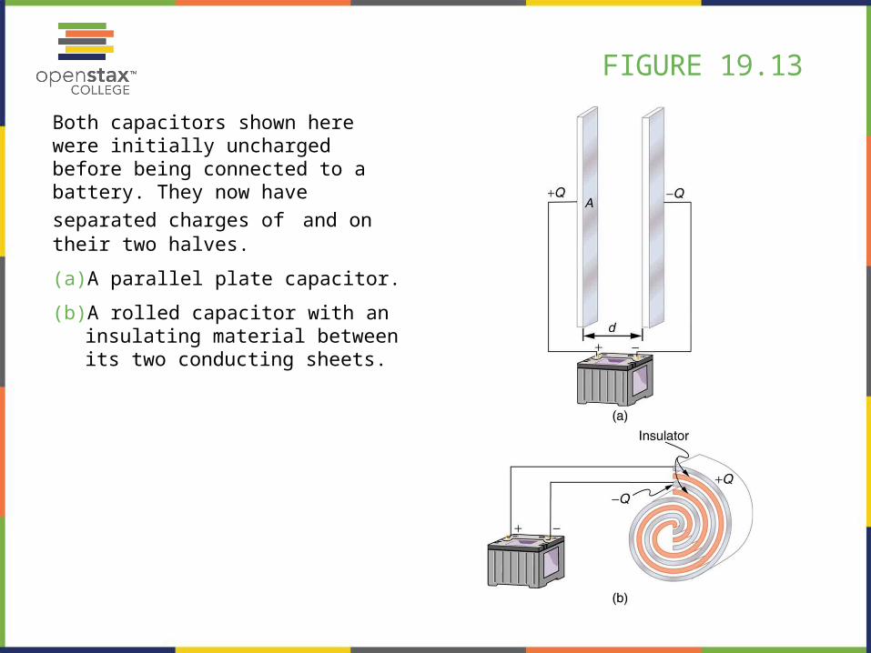
FIGURE 19.13
Both capacitors shown here were initially uncharged before being connected to a battery. They now have separated
charges of and on their two halves.
(a) A parallel plate capacitor.
(b) A rolled capacitor with an insulating material between its two conducting sheets.
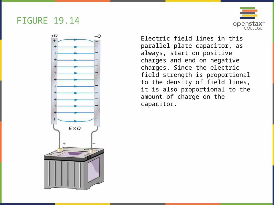
FIGURE 19.14
Electric field lines in this parallel plate capacitor, as always, start on positive charges and end on negative charges. Since the electric field strength is proportional to the density of field lines, it is also proportional to the amount of charge on the capacitor.
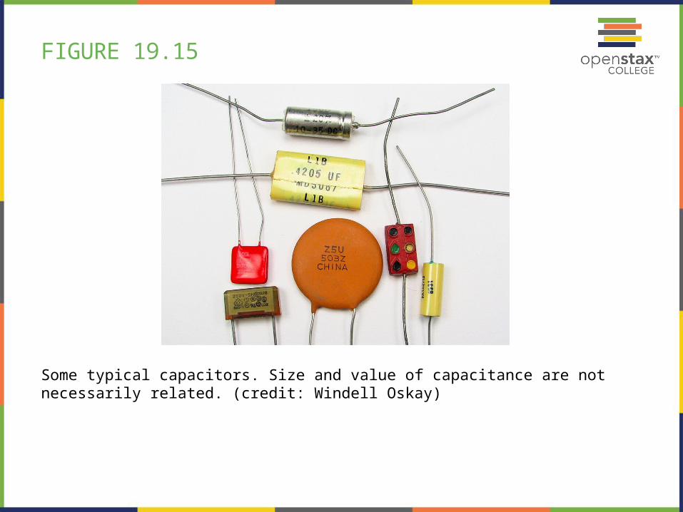
FIGURE 19.15
Some typical capacitors. Size and value of capacitance are not necessarily related. (credit: Windell Oskay)
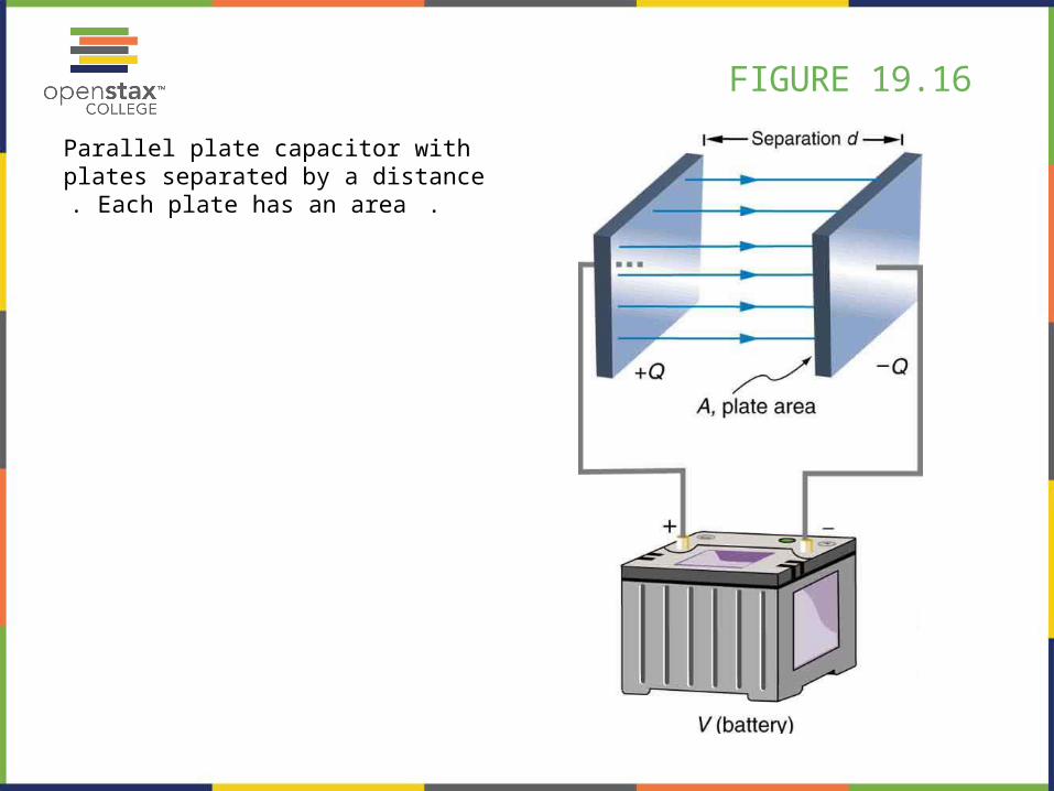
FIGURE 19.16
Parallel plate capacitor with plates separated by a distance . Each plate has an area .
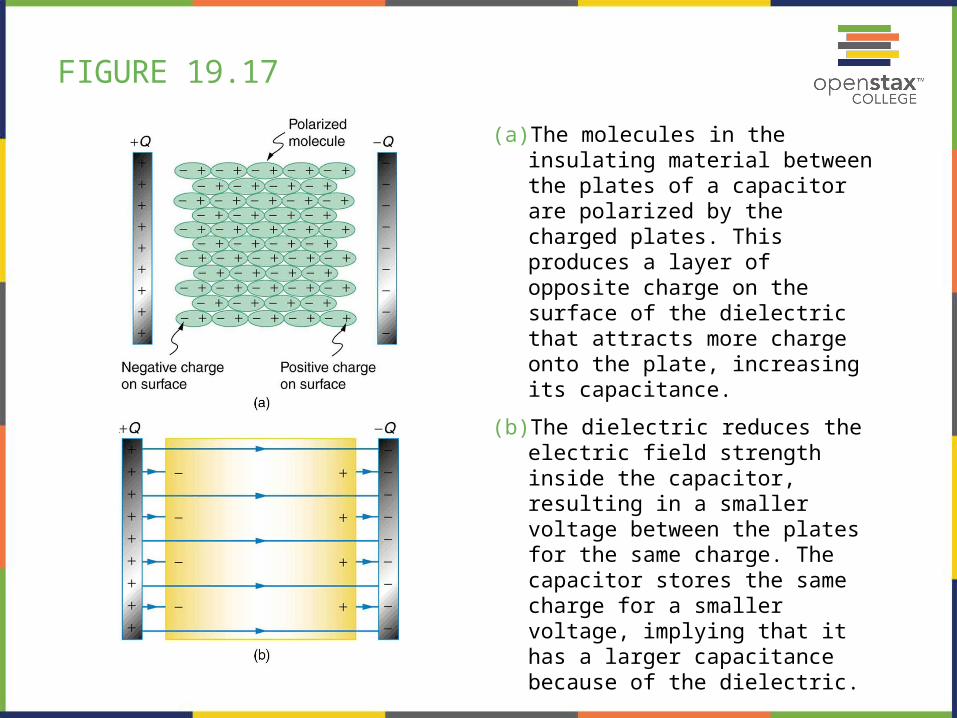
FIGURE 19.17
(a) The molecules in the insulating material between the plates of a capacitor are polarized by the charged plates. This produces a layer of opposite charge on the surface of the dielectric that attracts more charge onto the plate, increasing its capacitance.
(b) The dielectric reduces the electric field strength inside the capacitor, resulting in a smaller voltage between the plates for the same charge. The capacitor stores the same charge for a smaller voltage, implying that it has a larger capacitance because of the dielectric.
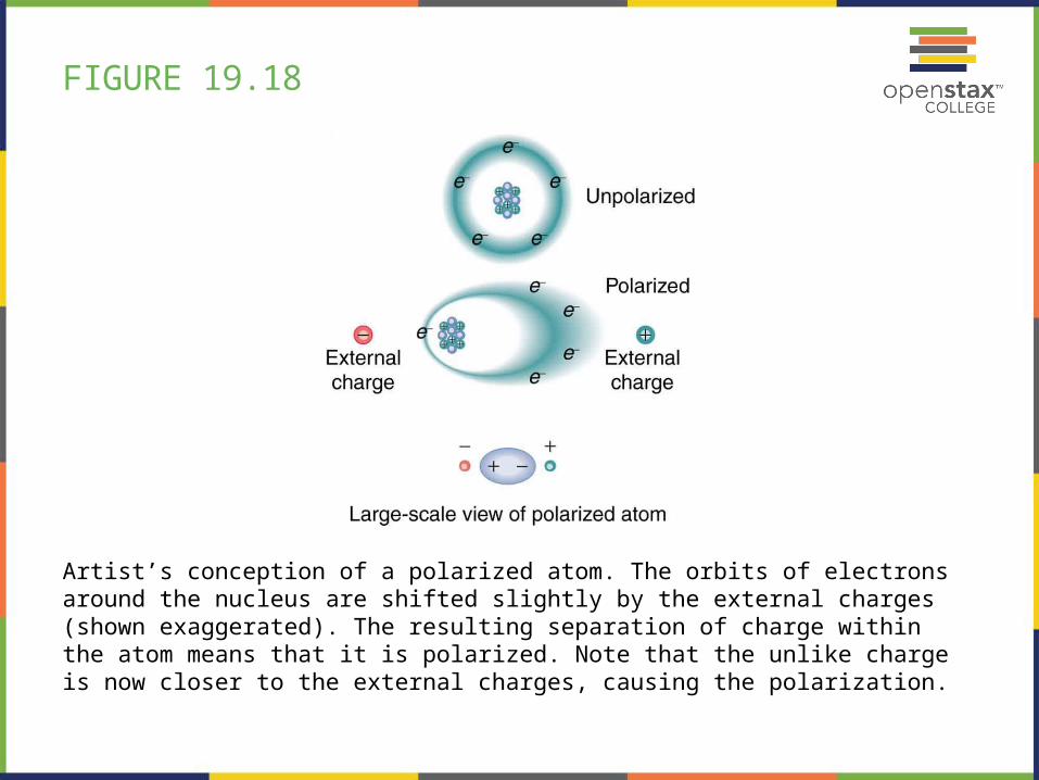
FIGURE 19.18
Artist’s conception of a polarized atom. The orbits of electrons around the nucleus are shifted slightly by the external charges (shown exaggerated). The resulting separation of charge within the atom means that it is polarized. Note that the unlike charge is now closer to the external charges, causing the polarization.

FIGURE 19.19
Artist’s conception of a water molecule. There is an inherent separation of charge, and so water is a polar molecule. Electrons in the molecule are attracted to the oxygen nucleus and leave an excess of positive charge near the two hydrogen nuclei. (Note that the schematic on the right is a rough illustration of the distribution of electronsin the water molecule. It does not show the actual numbers of protons and electrons involved in the structure.)
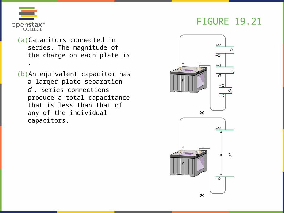
FIGURE 19.21
(a) Capacitors connected in series. The magnitude of the charge on each plate is .
(b) An equivalent capacitor has a larger plate separation d . Series connections produce a total capacitance that is less than that of any of the individual capacitors.
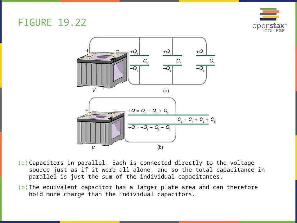
FIGURE 19.22
(a) Capacitors in parallel. Each is connected directly to the voltage source just as if it were all alone, and so the total capacitance in parallel is just the sum of the individual capacitances.
(b) The equivalent capacitor has a larger plate area and can therefore hold more charge than the individual capacitors.
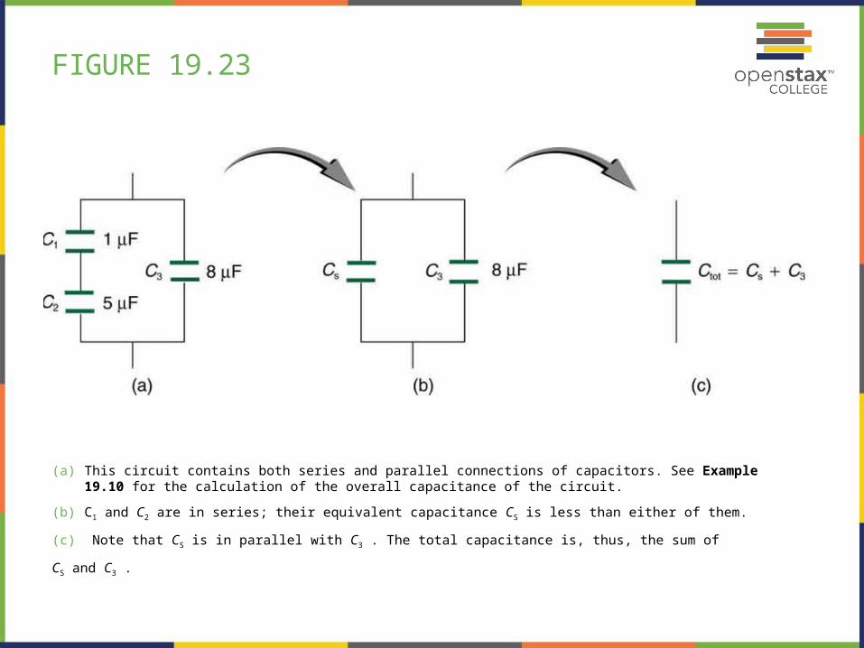
FIGURE 19.23
(a) This circuit contains both series and parallel connections of capacitors. See Example 19.10 for the calculation of the overall capacitance of the circuit.
(b) C1 and C2 are in series; their equivalent capacitance CS is less than either of them.
(c) Note that CS is in parallel with C3 . The total capacitance is, thus, the sum of
CS and C3 .
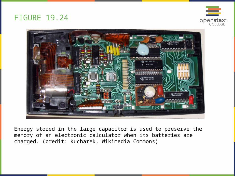
FIGURE 19.24
Energy stored in the large capacitor is used to preserve the memory of an electronic calculator when its batteries are charged. (credit: Kucharek, Wikimedia Commons)
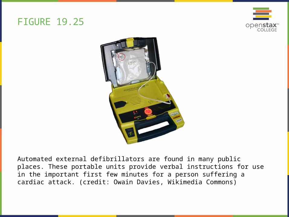
FIGURE 19.25
Automated external defibrillators are found in many public places. These portable units provide verbal instructions for use in the important first few minutes for a person suffering a cardiac attack. (credit: Owain Davies, Wikimedia Commons)
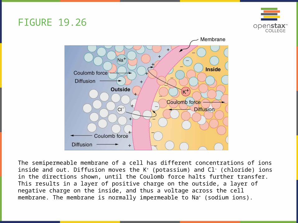
FIGURE 19.26
The semipermeable membrane of a cell has different concentrations of ions inside and out. Diffusion moves the K+ (potassium) and Cl– (chloride) ions in the directions shown, until the Coulomb force halts further transfer. This results in a layer of positive charge on the outside, a layer of negative charge on the inside, and thus a voltage across the cell membrane. The membrane is normally impermeable to Na+ (sodium ions).
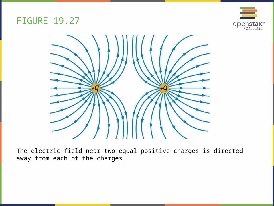
FIGURE 19.27
The electric field near two equal positive charges is directed away from each of the charges.
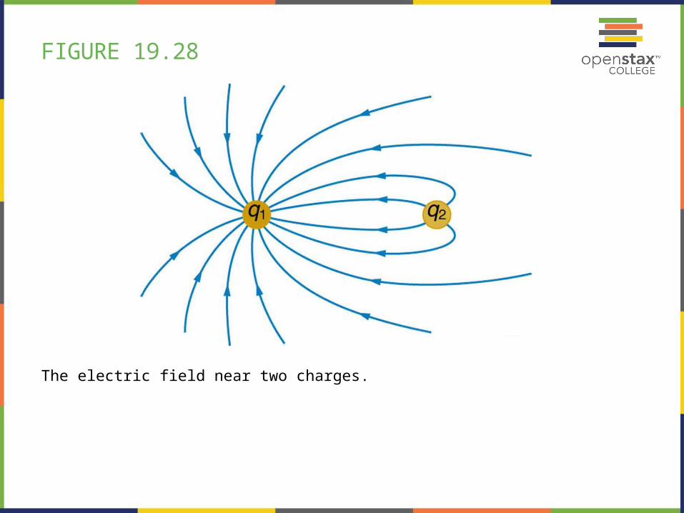
FIGURE 19.28
The electric field near two charges.
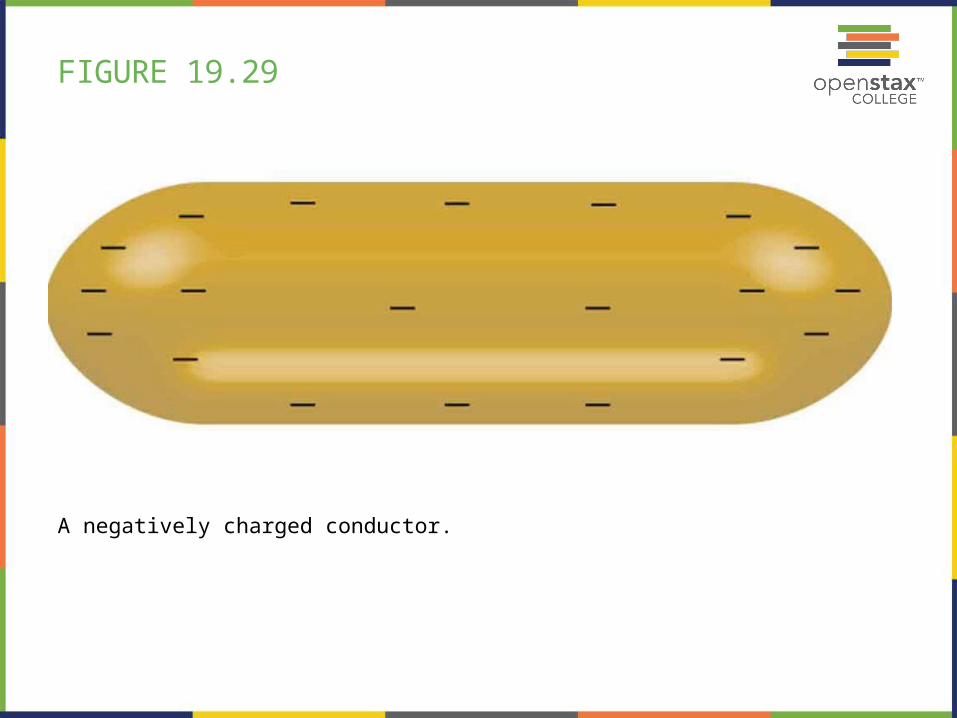
FIGURE 19.29
A negatively charged conductor.
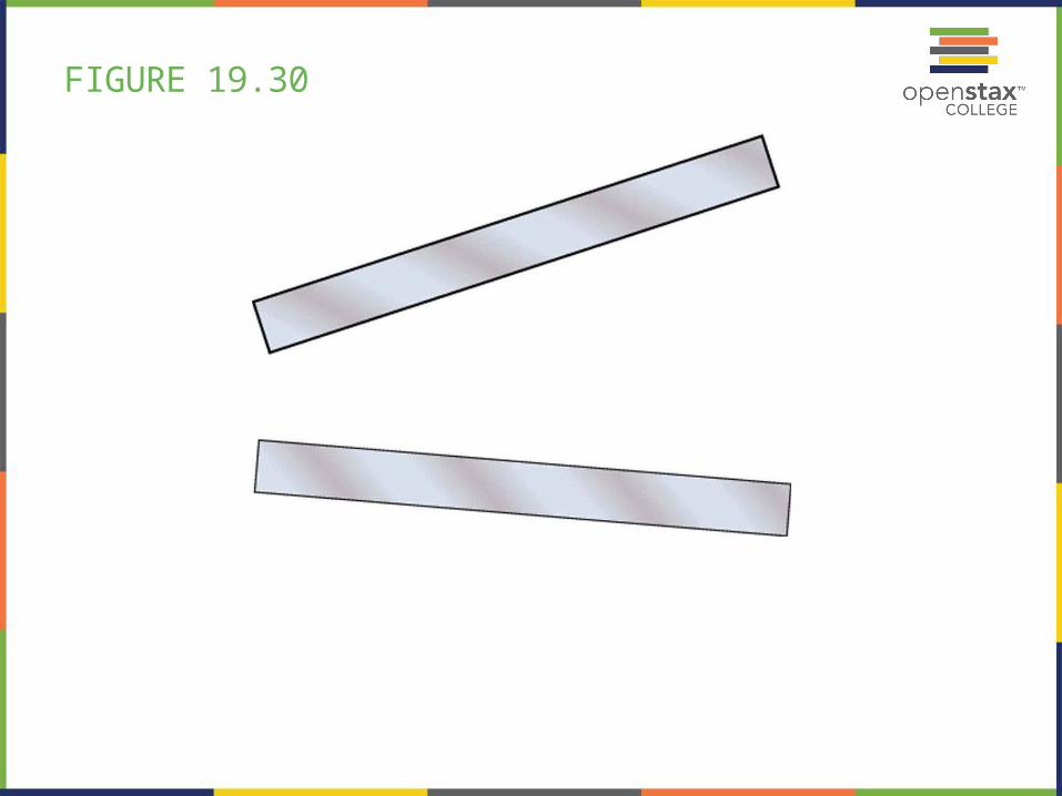
FIGURE 19.30
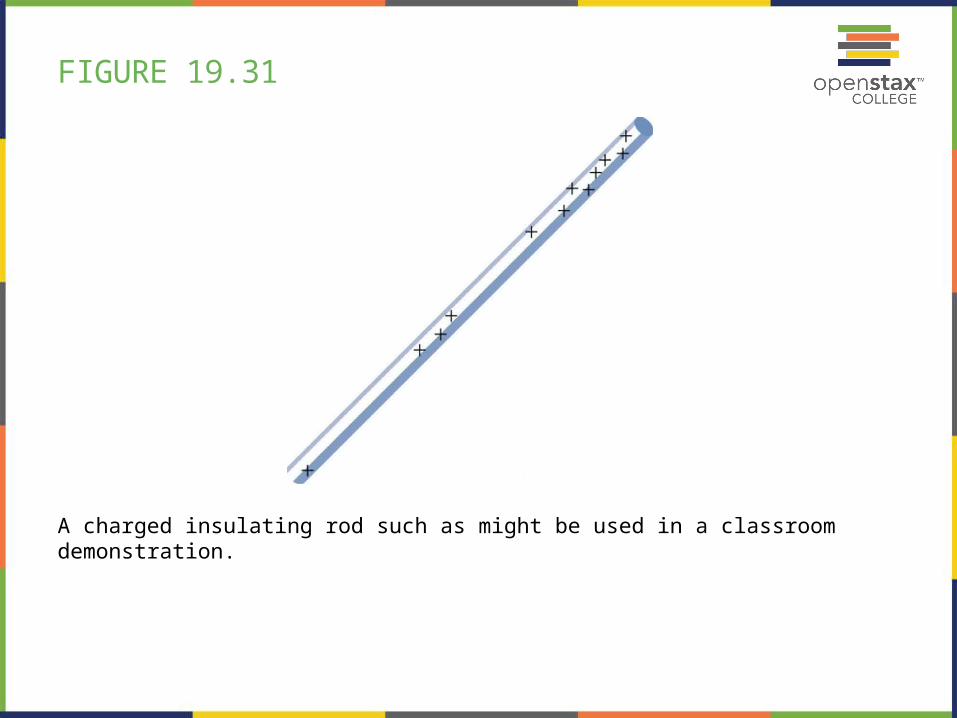
FIGURE 19.31
A charged insulating rod such as might be used in a classroom demonstration.

FIGURE 19.32
Lesser electric ray (Narcine bancroftii) (credit: National Oceanic and Atmospheric Administration, NOAA's Fisheries Collection).
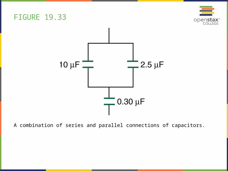
FIGURE 19.33
A combination of series and parallel connections of capacitors.
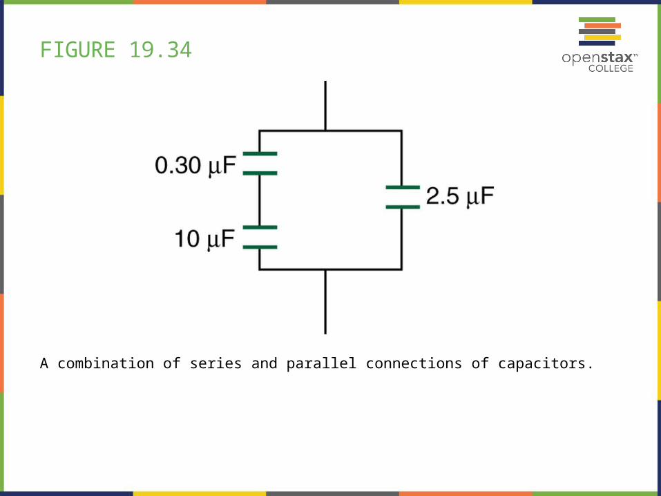
FIGURE 19.34
A combination of series and parallel connections of capacitors.
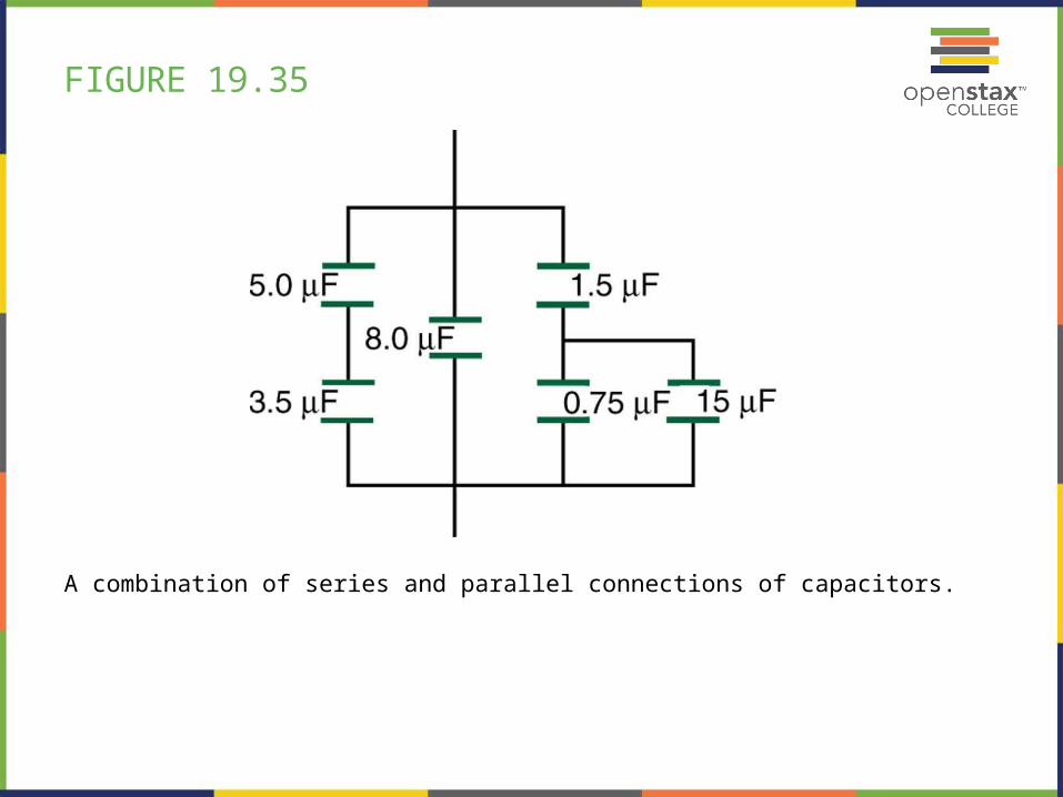
FIGURE 19.35
A combination of series and parallel connections of capacitors.

This PowerPoint file is copyright 2011-2013, Rice University. All Rights Reserved.
Related Documents