BRITISH STANDARD BS EN 10219-2:2006 Cold formed welded structural hollow sections of non-alloy and fine grain steels — Part 2: Tolerances, dimensions and sectional properties The European Standard EN 10219-2:2006 has the status of a British Standard ICS 77.140.75

Welcome message from author
This document is posted to help you gain knowledge. Please leave a comment to let me know what you think about it! Share it to your friends and learn new things together.
Transcript

BRITISH STANDARD
BS EN10219-2:2006Cold formed welded structural hollow sections of non-alloy and fine grain steels —
Part 2: Tolerances, dimensions and sectional properties
The European Standard EN 10219-2:2006 has the status of a British Standard
ICS 77.140.75
�������������� ���������������������������������������������������

BS EN 10219-2:2006
This British Standard was published under the authority of the Standards Policy and Strategy Committee on 31 May 2006
© BSI 2006
ISBN 0 580 48464 5
National foreword
This British Standard is the official English language version of EN 10219-2:2006. It supersedes BS EN 10219-2:1997 which is withdrawn.
The UK participation in its preparation was entrusted to Technical Committee ISE/12, Structural steel, which has the responsibility to:
A list of organizations represented on this committee can be obtained on request to its secretary.
Cross-references
The British Standards which implement international or European publications referred to in this document may be found in the BSI Catalogue under the section entitled “International Standards Correspondence Index”, or by using the “Search” facility of the BSI Electronic Catalogue or of British Standards Online.
This publication does not purport to include all the necessary provisions of a contract. Users are responsible for its correct application.
Compliance with a British Standard does not of itself confer immunity from legal obligations.
— aid enquirers to understand the text;
— present to the responsible international/European committee any enquiries on the interpretation, or proposals for change, and keep UK interests informed;
— monitor related international and European developments and promulgate them in the UK.
Summary of pages
This document comprises a front cover, an inside front cover, the EN title page, pages 2 to 36, an inside back cover and a back cover.
The BSI copyright notice displayed in this document indicates when the document was last issued.
Amendments issued since publication
Amd. No. Date Comments

EUROPEAN STANDARD
NORME EUROPÉENNE
EUROPÄISCHE NORM
EN 10219-2
April 2006
ICS 77.140.75 Supersedes EN 10219-2:1997
English Version
Cold formed welded structural hollow sections of non-alloy andfine grain steels - Part 2: Tolerances, dimensions and sectional
properties
Profils creux pour la construction soudés, formés à froid enaciers non alliés et à grains fins - Partie 2 : Tolérances,
dimensions et caractéristiques de profil
Kaltgefertigte geschweißte Hohlprofile für den Stahlbau ausunlegierten Baustählen und aus Feinkornbaustählen - Teil
2: Grenzabmaße, Maße und statische Werte
This European Standard was approved by CEN on 16 March 2006.
CEN members are bound to comply with the CEN/CENELEC Internal Regulations which stipulate the conditions for giving this EuropeanStandard the status of a national standard without any alteration. Up-to-date lists and bibliographical references concerning such nationalstandards may be obtained on application to the Central Secretariat or to any CEN member.
This European Standard exists in three official versions (English, French, German). A version in any other language made by translationunder the responsibility of a CEN member into its own language and notified to the Central Secretariat has the same status as the officialversions.
CEN members are the national standards bodies of Austria, Belgium, Cyprus, Czech Republic, Denmark, Estonia, Finland, France,Germany, Greece, Hungary, Iceland, Ireland, Italy, Latvia, Lithuania, Luxembourg, Malta, Netherlands, Norway, Poland, Portugal, Romania,Slovakia, Slovenia, Spain, Sweden, Switzerland and United Kingdom.
EUROPEAN COMMITTEE FOR STANDARDIZATIONC OM ITÉ EUR OP ÉEN DE NOR M ALIS AT IONEUROPÄISCHES KOMITEE FÜR NORMUNG
Management Centre: rue de Stassart, 36 B-1050 Brussels
© 2006 CEN All rights of exploitation in any form and by any means reservedworldwide for CEN national Members.
Ref. No. EN 10219-2:2006: E

EN 10219-2:2006 (E)
2
Contents
Foreword ..........................................................................................................................................................3 1 Scope ...................................................................................................................................................4 2 Normative references .........................................................................................................................4 3 Terms and definitions.........................................................................................................................4 4 Symbols...............................................................................................................................................4 5 Information to be obtained by the manufacturer ..............................................................................5 6 Tolerances...........................................................................................................................................5 7 Measurement of size and shape ........................................................................................................8 7.1 General ................................................................................................................................................8 7.2 Outside dimensions............................................................................................................................8 7.3 Thickness ............................................................................................................................................8 7.4 Out-of-roundness................................................................................................................................9 7.5 Concavity and convexity ....................................................................................................................9 7.6 Squareness of sides .........................................................................................................................10 7.7 External corner profile......................................................................................................................11 7.8 Twist...................................................................................................................................................11 7.9 Straightness ......................................................................................................................................12 8 Dimensions and sectional properties..............................................................................................12 Annex A (informative) Additional tolerances for piling tube .....................................................................14 A.1 General ..............................................................................................................................................14 A.2 Out of roundness tolerance .............................................................................................................14 A.3 Accidental eccentricity tolerance ....................................................................................................15 A.4 Dimple tolerance ...............................................................................................................................17 Annex B (normative) Formulae for the calculation of sectional properties .............................................20 B.1 General ..............................................................................................................................................20 B.2 Circular hollow sections...................................................................................................................20 B.3 Rectangular, or square, hollow sections.........................................................................................21 Annex C (normative) Sectional properties for a limited range of standard sizes ....................................24 Bibliography...................................................................................................................................................36

EN 10219-2:2006 (E)
3
Foreword
This European Standard (EN 10219-2:2006) has been prepared by Technical Committee ECISS/TC 10 “Structural steels - Grades and qualities”, the secretariat of which is held by NEN.
This European Standard shall be given the status of a national standard, either by publication of an identical text or by endorsement, at the latest by October 2006, and conflicting national standards shall be withdrawn at the latest by October 2006.
This European Standard supersedes EN 10219—2:1997.
This standard consists of the following parts under the general title 'Cold formed welded structural hollow sections of non-alloy and fine grain steels':
− Part 1: Technical delivery conditions
− Part 2: Tolerances, dimensions and sectional properties
It forms part of a series of standards on hollow sections together with EN 10210-1 and 2, which are also under revision.
According to the CEN/CENELEC Internal Regulations, the national standards organizations of the following countries are bound to implement this European Standard: Austria, Belgium, Cyprus, Czech Republic, Denmark, Estonia, Finland, France, Germany, Greece, Hungary, Iceland, Ireland, Italy, Latvia, Lithuania, Luxembourg, Malta, Netherlands, Norway, Poland, Portugal, Romania, Slovakia, Slovenia, Spain, Sweden, Switzerland and United Kingdom.

EN 10219-2:2006 (E)
4
1 Scope
This part of EN 10219 specifies tolerances for cold formed welded circular, square and rectangular structural hollow sections, manufactured in wall thicknesses up to 40 mm, in the following size ranges:
Circular: Outside diameters up to 2 500 mm
Square: Outside dimensions up to 500 mm x 500 mm
Rectangular: Outside dimensions up to 500 mm x 300 mm
The formulae for calculating sectional properties of sections manufactured to the dimensional tolerances of this standard, to be used for the purposes of structural design, are given in Annex B.
Dimensions and sectional properties for a limited range of sizes are given in Annex C.
Technical delivery conditions are specified in EN 10219-1.
NOTE The designation of the sections' major axis (yy) and its minor axis (zz) align with the axis designation used for structural design in the structural Eurocodes.
2 Normative references
The following referenced documents are indispensable for the application of this European Standard. For dated references, only the edition cited applies. For undated references, the latest edition of the referenced document (including any amendments) applies.
EN 10219-1:2006, Cold formed welded structural hollow sections of non-alloy and fine grain steels — Part 1: Technical delivery conditions
3 Terms and definitions
For the purposes of this European Standard, the terms and definitions given in EN 10219-1:2006 apply.
4 Symbols
For the purposes of this European Standard, the symbols defined in Table 1 apply.

EN 10219-2:2006 (E)
5
Table 1 — Symbols and definitions
Symbol Unit Definition A cm2 Cross-sectional area As m2/m Superficial area per metre length B mm Specified side dimension of a square hollow section. Specified dimension of
the shorter side of a rectangular hollow section C1/C2 mm Length of corner region of a square or rectangular hollow section Ct cm3 Torsional modulus constant D mm Specified outside diameter of a circular hollow section Dmax/Dmin mm The maximum and minimum outside diameter of a circular hollow section
measured in the same plane e mm Deviation from straightness H mm Specified dimension of the longer side of a rectangular hollow section I cm4 Second moment of area It cm4 Torsional inertia constant (polar moment of inertia in the case of circular
hollow sections only) i cm Radius of gyration L mm Length M kg/m Mass per unit length O % Out-of-roundness R mm External corner radius of a square or rectangular hollow section T mm Specified thickness V mm Total measured twist V1 mm Twist measured at one end of a section Wel cm3 Elastic section modulus Wpl cm3 Plastic section modulus x1 mm Concavity of a side of a square or rectangular hollow section x2 mm Convexity of a side of a square or rectangular hollow section yy — Axis of cross-section, major axis of a rectangular hollow section zz — Axis of cross-section, minor axis of a rectangular hollow section θ º Angle between adjacent sides of a square or rectangular hollow section
5 Information to be obtained by the manufacturer
The following mandatory information from this part of EN 10219 shall be obtained by the manufacturer at the time of enquiry and order.
a) The type of length, length range or length (see Table 4).
b) The dimensions (see Clause 8).
NOTE This information is included in the list of information to be obtained by the manufacturer contained in EN 10219-1.
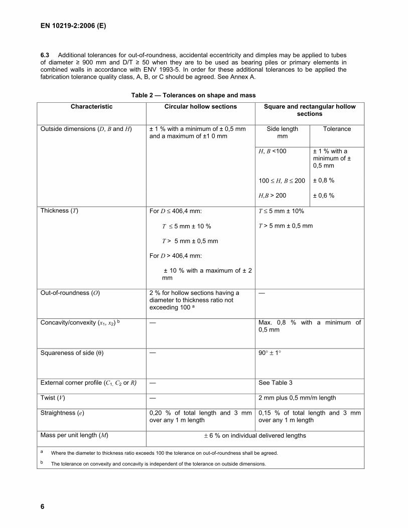
6 Tolerances
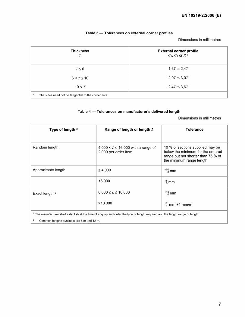
6.1 Tolerances shall not exceed the values given in Table 2 for shape and mass, Table 3 for external corner profiles, Table 4 for manufacturer's delivered length and Table 5 for the height of the internal and external weld bead of submerged arc welded hollow sections.
6.2 The internal corners of square and rectangular hollow sections shall be rounded.
NOTE The internal corner profile is not specified.
EN 10219-2:2006 (E)
6
6.3 Additional tolerances for out-of-roundness, accidental eccentricity and dimples may be applied to tubes of diameter ≥ 900 mm and D/T ≥ 50 when they are to be used as bearing piles or primary elements in combined walls in accordance with ENV 1993-5. In order for these additional tolerances to be applied the fabrication tolerance quality class, A, B, or C should be agreed. See Annex A.
Table 2 — Tolerances on shape and mass
Characteristic Circular hollow sections Square and rectangular hollow sections
Outside dimensions (D, B and H) ± 1 % with a minimum of ± 0,5 mm and a maximum of ±1 0 mm
Side length mm
Tolerance
H, B <100 ± 1 % with a minimum of ± 0,5 mm
100 ≤ H, B ≤ 200 ± 0,8 %
H,B > 200 ± 0,6 %
Thickness (T) For D ≤ 406,4 mm:
T ≤ 5 mm ± 10 %
T > 5 mm ± 0,5 mm
For D > 406,4 mm:
± 10 % with a maximum of ± 2 mm
T ≤ 5 mm ± 10%
T > 5 mm ± 0,5 mm
Out-of-roundness (O) 2 % for hollow sections having a diameter to thickness ratio not exceeding 100 a
—
Concavity/convexity (x1, x2) b
— Max. 0,8 % with a minimum of 0,5 mm
Squareness of side (θ)
— 90° ± 1°
External corner profile (C1, C2 or R) — See Table 3
Twist (V) — 2 mm plus 0,5 mm/m length
Straightness (e) 0,20 % of total length and 3 mm over any 1 m length
0,15 % of total length and 3 mm over any 1 m length
Mass per unit length (M) ± 6 % on individual delivered lengths
a Where the diameter to thickness ratio exceeds 100 the tolerance on out-of-roundness shall be agreed.
b The tolerance on convexity and concavity is independent of the tolerance on outside dimensions.
EN 10219-2:2006 (E)
7
Table 3 — Tolerances on external corner profiles
Dimensions in millimetres
Thickness T
External corner profile C1, C2 or R a
T ≤ 6 1,6T to 2,4T
6 < T ≤ 10 2,0T to 3,0T
10 < T 2,4T to 3,6T
a The sides need not be tangential to the corner arcs.
Table 4 — Tolerances on manufacturer's delivered length
Dimensions in millimetres
Type of length a Range of length or length L
Tolerance
Random length 4 000 < L ≤ 16 000 with a range of 2 000 per order item
10 % of sections supplied may be below the minimum for the ordered range but not shorter than 75 % of the minimum range length
Approximate length ≥ 4 000 500
+ mm
<6 000 50
+ mm
6 000 ≤ L ≤ 10 000 150
+ mm Exact length b
>10 000 50
+ mm +1 mm/m
a The manufacturer shall establish at the time of enquiry and order the type of length required and the length range or length.
b Common lengths available are 6 m and 12 m.

EN 10219-2:2006 (E)
8
Table 5 — Tolerance on height of internal and external weld bead for submerged arc welded hollow sections
Dimensions in millimetres
Thickness, T Maximum weld bead height
≤14,2 3,5
>14,2 4,8
7 Measurement of size and shape
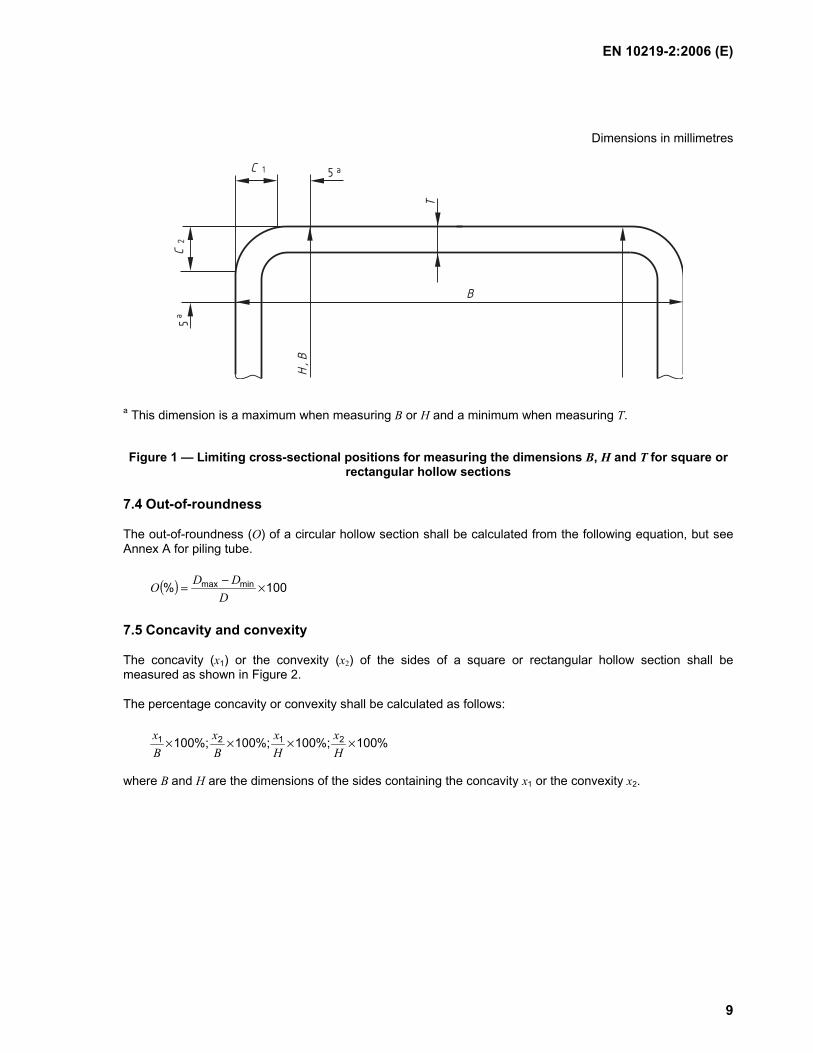
7.1 General
All external dimensions, including out-of-roundness, shall be measured at a distance from the end of the hollow section of not less than D for circular sections, B for square sections or H for rectangular sections, with a minimum of 100 mm.
7.2 Outside dimensions
For circular hollow sections the diameter (D) shall be measured either directly, e.g. using a calliper gauge, or by circumference tape at the discretion of the manufacturer.
The limiting cross-sectional positions for measuring B and H for square and rectangular hollow sections are shown in Figure 1.
7.3 Thickness
The thickness (T) shall be measured at a position not less than 2T from the weld.
The limiting cross-sectional positions for measuring the thickness of square and rectangular hollow sections are shown in Figure 1.
NOTE Thickness is normally measured within a distance of half the outside diameter or half the dimension of the longer side from the end of the section.
EN 10219-2:2006 (E)
9
Dimensions in millimetres
C 51C
2
H , B
T
B
5a
a
a This dimension is a maximum when measuring B or H and a minimum when measuring T.
Figure 1 — Limiting cross-sectional positions for measuring the dimensions B, H and T for square or rectangular hollow sections
7.4 Out-of-roundness
The out-of-roundness (O) of a circular hollow section shall be calculated from the following equation, but see Annex A for piling tube.
( ) 100% minmax ×−=D
DDO
7.5 Concavity and convexity
The concavity (x1) or the convexity (x2) of the sides of a square or rectangular hollow section shall be measured as shown in Figure 2.
The percentage concavity or convexity shall be calculated as follows:
%100%;100%;100%;100 2121 ××××Hx
Hx
Bx
Bx
where B and H are the dimensions of the sides containing the concavity x1 or the convexity x2.

EN 10219-2:2006 (E)
10
C ,
C1
2
B , H
BA
x 1x
1x
A B
2
C ,
C1
2
2x
Figure 2 — Measurement of concavity/convexity of square or rectangular hollow sections
7.6 Squareness of sides
The deviation from squareness of the sides of a square or rectangular hollow section shall be measured as the difference between 90º and θ as shown in Figure 3.
θ
Figure 3 — Squareness of sides of square or rectangular hollow sections
EN 10219-2:2006 (E)
11
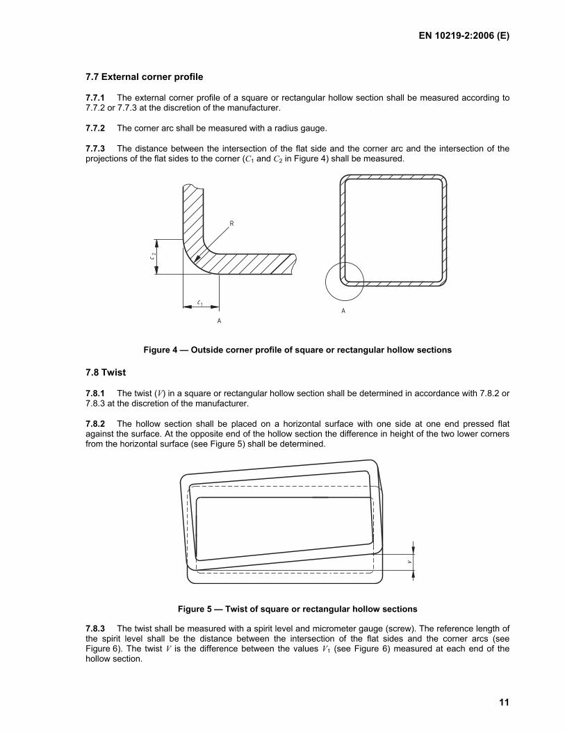
7.7 External corner profile
7.7.1 The external corner profile of a square or rectangular hollow section shall be measured according to 7.7.2 or 7.7.3 at the discretion of the manufacturer.
7.7.2 The corner arc shall be measured with a radius gauge.
7.7.3 The distance between the intersection of the flat side and the corner arc and the intersection of the projections of the flat sides to the corner (C1 and C2 in Figure 4) shall be measured.
c 1
c2
A
A
R
Figure 4 — Outside corner profile of square or rectangular hollow sections
7.8 Twist
7.8.1 The twist (V) in a square or rectangular hollow section shall be determined in accordance with 7.8.2 or 7.8.3 at the discretion of the manufacturer.
7.8.2 The hollow section shall be placed on a horizontal surface with one side at one end pressed flat against the surface. At the opposite end of the hollow section the difference in height of the two lower corners from the horizontal surface (see Figure 5) shall be determined.
v
Figure 5 — Twist of square or rectangular hollow sections
7.8.3 The twist shall be measured with a spirit level and micrometer gauge (screw). The reference length of the spirit level shall be the distance between the intersection of the flat sides and the corner arcs (see Figure 6). The twist V is the difference between the values V1 (see Figure 6) measured at each end of the hollow section.

EN 10219-2:2006 (E)
12
1V
1
2
Key 1 Spirit level 2 H for rectangular sections, B for square sections
Figure 6 — Measurement of twist
7.9 Straightness
The deviation from straightness (e) of the total length of a hollow section shall be measured at the point of maximum departure of the hollow section from a straight line connecting its two ends, as shown in Figure 7 where L is the manufacturer's delivered length. The percentage deviation from straightness shall be calculated as follows:
%100×Le
In addition the local deviation (e) from straightness of a hollow section, measured at any point along its length from a straight line length L of 1 m, shall be not more than 3 mm.
e
L
Figure 7 — Measurement of deviation from straightness
8 Dimensions and sectional properties
The nominal sectional properties of hollow sections within the scope of this part of EN 10219 and manufactured to the dimensional tolerances of this standard, required for the purposes of structural design, shall be calculated in accordance with Annex B.
The sectional properties for a limited range of standard sizes of cold formed hollow sections are given in Table C.1 for circular sections, Table C.2 for square sections and Table C.3 for rectangular sections. These sectional properties were calculated from the formulae given in Annex B.

EN 10219-2:2006 (E)
13
NOTE Not all sizes and thicknesses shown in Tables C.1, C.2 and C.3 are available from all manufacturers and the user is recommended to check availability. Other sizes and thicknesses within the scope of this standard may be available.

EN 10219-2:2006 (E)
14
Annex A (informative)
Additional tolerances for piling tube
A.1 General
This annex contains guidance on additional tolerances that can be applied to tubes when they are to be used as bearing piles or primary elements in combined walls in accordance with ENV 1993-5. These requirements are generally relevant to tubes of diameter ≥ 900 mm and D/T ≥ 100.
For verification of tubular piles subject to shell buckling, ENV 1993-5: Piling refers to ENV 1993-1-6. Shell buckling is partly governed by geometrical imperfections of the shell due to out-of-roundness, accidental eccentricity and dimples. ENV 1993-1-6 specifies limits for each of these geometrical imperfections, based on the concept of fabrication quality classes. Details of how to assess out-of-roundness, accidental eccentricity and dimples, and the recommended maximum permitted values for each fabrication quality class, are given in A.2, A.3 and A.4.
NOTE 1 See ENV 1993-1-6 for further details of fabrication tolerance quality classes, their design implications and for definitions and use of symbols.
NOTE 2 The values of certain parameters, given in Tables A.1, A.2 and A.3 may be subject to change by national application of ENV 1993-1-6. Nationally determined parameters will be given in the relevant National Annex of ENV 1993-1-6.
A.2 Out of roundness tolerance
Out-of-roundness of a tubular pile is assessed in terms of the parameter Ur the difference between the maximum and minimum values of the measured internal diameter, relative to the nominal inside diameter, see Figure A.1, given by:
Ur = nom
minmax
ddd −
Where:
dmax is the maximum measured internal diameter;
dmin is the minimum measured internal diameter;
dnom is the nominal inside diameter (d = D – 2T, see B.2).
An appropriate number of diameters should be measured in order to identify the maximum and minimum values.

EN 10219-2:2006 (E)
15
dmin
dmax
dnom
Figure A.1 — Assessment of dmin and dmax and relationship to d
The out-of-roundness parameter Ur should satisfy the condition:
Ur ≤ Ur, max
where:
Ur, max is the maximum permitted value for the out-of-roundness parameter.
Recommended values for each fabrication tolerance quality class are given in Table A.1.
Table A.1 — Maximum permitted values for out-of-roundness parameter Ur, max
Dimensions in mm
Diameter range
d ≤ 500 500 < d < 1250 1250 ≤ d Fabrication
tolerance quality class
Description
Value of Ur max a
Class A Excellent 0,14 0,007+0,0093 (1,25 - d) 0,007
Class B High 0,02 0,010+0,0133 (1,25 - d) 0,01
Class C Normal 0,03 0,015+0,020 (1,25 - d) 0,015
a The values of this parameter may be subject to change by national application of ENV 1993-1-6. If in doubt, reference should be made to the relevant National Annex of ENV 1993-1-6.
A.3 Accidental eccentricity tolerance
Accidental eccentricity, the unintentional eccentricity due to misalignment of the tube walls at horizontal joints, is assessed in terms of the parameter Ue given by:
Ue = Tea

EN 10219-2:2006 (E)
16
where:
ea is the accidental eccentricity between the mid points of the tube walls at the joint, compared to their normal thickness;
T is the tube wall thickness.
NOTE For joints involving tubes of different thicknesses, it is recommended to refer to ENV 1993-1-6.
T
T
ea
Figure A.2 — Measurement of tube wall eccentricity (ea)
The accidental eccentricity ea should satisfy the condition:
ea ≤ ea, max
where:
ea, max is the maximum permitted accidental eccentricity.
Recommended values for each fabrication tolerance quality class are given in Table A.2.
The accidental eccentricity parameter Ue should satisfy the condition:
Ue ≤ Ue, max
where:
Ue, max is the maximum permitted value for the accidental eccentricity parameter.
Recommended values for each fabrication tolerance quality class are given in Table A.2.

EN 10219-2:2006 (E)
17
Table A.2 — Maximum permitted values for accidental eccentricity parameter Ue, max and for accidental eccentricity ea, max
Dimensions in mm
Fabrication tolerance quality
class Description Ue, max a ea, max
a
Class A Excellent 0,14 2
Class B High 0,2 3
Class C Normal 0,3 4
a The values of these parameters may be subject to change by national application of ENV 1993-1-6. If in doubt, reference should be made to the relevant National Annex of ENV 1993-1-6.
A.4 Dimple tolerance
The depth of initial dimples in the tube wall wo is measured, in both the meridontal and circumferential directions, using a measurement gauge, see Figure A.3, of length lg where:
a) meridontally and circumferentially lg = rT4
b) across welds lg = 25 T but lg ≤ 500 mm
The gauge used for meridontal measurements should be straight but that used for measurements in the circumferential direction should have a radius of curvature r where:
r = 2
)( TD −
NOTE For joints involving tubes of different thicknesses, it is recommended to refer to ENV 1993-1-6.

EN 10219-2:2006 (E)
18
T
wo
Ig
Figure A.3 — Measurement of depth wo of initial dimples
The level of initial dimples in the wall of the tubular pile is assessed in terms of the dimple tolerance parameter Ud given by:
Ud = g
o
lw
The dimple tolerance parameter Ud should satisfy the condition:
Ud ≤ Ud, max
where:
Ud, max is the maximum permitted value for the dimple tolerance parameter.
Recommended values for each fabrication tolerance class are given in Table A.3.

EN 10219-2:2006 (E)
19
Table A.3 — Maximum permitted values for dimple tolerance parameter Ud, max
Dimensions in mm
Fabrication tolerance
quality class Description Ud, max
Class A Excellent 0,006
Class B High 0,01
Class C Normal 0,016
a The values of this parameter may be subject to change by national application of ENV 1993-1-6. If in doubt, reference should be made to the National Annex of ENV 1993-1-6.

EN 10219-2:2006 (E)
20
Annex B (normative)
Formulae for the calculation of sectional properties
B.1 General
Tables C.1, C.2 and C.3 of this standard give nominal sectional properties for a limited range of sizes of cold formed hollow sections. The nominal sectional properties of hollow sections supplied to the requirements of this standard shall be calculated using the formulae given below.
NOTE The designation of the sections' major axis (yy) and its minor axis (zz) align with the axis designation used for structural design in the structural Eurocodes. This is a change from previous axis designations.
B.2 Circular hollow sections
The sectional properties for circular hollow sections in Table C.1 are calculated using the formulae given below.
Specified outside diameter (D) (mm)
Specified thickness (T) (mm)
Inside diameter (d = D - 2T) (mm)
These parameters, which characterize the shape of circular hollow sections, may vary within the tolerances allowed by this standard and the sectional properties still remain valid.
Superficial area per metre length 310
DsA π=
(m2/m)
Cross-sectional area ( )2
22
104 ×−= dDA π
(cm2)
Mass per unit length M = 0,785 × A (kg/m)
Second moment of area ( )4
44
1064 ×−= dDI π
(cm4)
Radius of gyration
AIi =
(cm)

EN 10219-2:2006 (E)
21
Elastic section modulus
DIW 102
el×=
(cm3)
Plastic section modulus 3
33
pl 106 ×−= dDW
(cm3)
Torsional inertia constant (polar moment of inertia)
IIt 2= (cm4)
Torsional modulus constant Ct = 2Wel (cm3)
B.3 Rectangular, or square, hollow sections
The sectional properties for square hollow sections in Table C.2 and for rectangular hollow sections in Table C.3 are calculated using the formulae given below.
Specified side dimension of a square hollow section or shorter side of a rectangular hollow section
(B) (mm)
Specified dimension of the longer side of a rectangular hollow section (H) (mm)
Specified thickness (T) (mm)
External corner radius (ro) for calculation is:
for thicknesses ≤ 6 mm 2,0 T (mm)
for thicknesses > 6 mm ≤ 10 mm 2,5 T (mm)
for thicknesses > 10mm 3,0 T (mm)
Internal corner radius (ri) for calculation is:
for thicknesses ≤ 6 mm 1,0 T (mm)
for thicknesses > 6 mm and ≤ 10 mm 1,5 T (mm)
for thicknesses > 10 mm 2,0 T (mm)
These parameters, which characterize the geometric shape of rectangular, or square, hollow sections, may vary within the tolerances allowed by this standard and the sectional properties still remain valid.
Superficial area per metre length ( )oo3s 410
2 rrBHA π+−+= (m2/m)

EN 10219-2:2006 (E)
22
Cross-sectional area ( ) ( )( )2
2i
2o
10422 rrTHBT
A−−−−+
=π
(cm2)
Mass per unit length M = 0,785A (kg/m)
Second moment of area
Major axis Iyy
( )( ) ( ) ( )
+++−−−−= 2
ξξξξ2
ggg
33
4 4412
221210
1 hAIhAITHTBBH
(cm4)
Minor axis Izz
( )( ) ( ) ( )
+++−−−−= 2
ξξξξ2
ggg
33
4 4412
221210
1 hAIhAITBTHHB
(cm4)
Radius of gyration
Major axis iyy =
AI yy
(cm)
Minor axis izz = A
I zz (cm)
Elastic section modulus
Major axis Wel yy = H
I yy2×10
(cm3)
Minor axis Wel zz = B
I zz2×10
(cm3)
Plastic section modulus
Major axis Wpl yy =
( )( ) ( ) ( )
+−−−− ξξgg
22
3 444
22410
1 hAhATHTBBH
(cm3)
Minor axis Wpl zz =
( )( ) ( ) ( )
+−−−− ξξgg
22
3 444
22410
1 hAhATBTHHB
(cm3)

EN 10219-2:2006 (E)
23
Torsional inertia constant
+= h
34t 2
3101 KAhTI
(cm4)
Torsional modulus constant
+
=TKT
IC
/10 t
t (cm3)
Where 2og 4
1 rA
−= π
(mm2)
2iξ 4
1 rA
−= π
(mm2)
Major axis og 3-12
3102
rHh
−−=
ππ
(mm)
(For minor axis substitute B for H.)
Major axis iξ 3-12
3102
2 rTHh
−−−=
ππ
(mm)
(For minor axis substitute B for H.)
( )4
og 31231
1631 rI
−
−−=π
π
(mm4)
( )4
i31231
1631 rI
−
−−=π
πξξ
(mm4)
h = 2[(B – T) + (H – T)] – 2Rc(4 - π) (mm)
Ah = (B – T) (H – T)] – R2c(4 - π) (mm)
hTA
K h2=
(mm2)
2io
crr
R+
= (mm)

EN 10219-2:2006 (E)
24
Annex C (normative)
Sectional properties for a limited range of standard sizes
Table C.1 — Nominal dimensions and sectional properties of a limited range of circular hollow sections (see Figure C.1)
Specified outside
diameter
Specified thickness
Mass per unit
length
Cross-sectional
area
Second moment of area
Radius of gyration
Elastic section
modulus
Plastic section
modulus
Torsional inertia
constant
Torsional modulus constant
Super- ficial area per metre
length
Nominal length
per tonne
D T M A I i Wel Wpl Lt Ct As mm mm kg/m cm2 cm4 cm cm3 cm3 cm4 cm3 m2/m m
21,3 2,0 0,95 1,21 0,571 0,686 0,536 0,748 1,14 1,07 0,067 1050 21,3 2,5 1,16 1,48 0,664 0,671 0,623 0,889 1,33 1,25 0,067 863 21,3 3,0 1,35 1,72 0,741 0,656 0,696 1,01 1,48 1,39 0,067 739 26,9 2,0 1,23 1,56 1,22 0,883 0,907 1,24 2,44 1,81 0,085 814 26,9 2,5 1,50 1,92 1,44 0,867 1,07 1,49 2,88 2,14 0,085 665 26,9 3,0 1,77 2,25 1,63 0,852 1,21 1,72 3,27 2,43 0,085 566 33,7 2,0 1,56 1,99 2,51 1,12 1,49 2,01 5,02 2,98 0,106 640 33,7 2,5 1,92 2,45 3,00 1,11 1,78 2,44 6,00 3,56 0,106 520 33,7 3,0 2,27 2,89 3,44 1,09 2,04 2,84 6,88 4,08 0,106 440 42,4 2,0 1,99 2,54 5,19 1,43 2,45 3,27 10,4 4,90 0,133 502 42,4 2,5 2,46 3,13 6,26 1,41 2,95 3,99 12,5 5,91 0,133 407 42,4 3,0 2,91 3,71 7,25 1,40 3,42 4,67 14,5 6,84 0,133 343 42,4 4,0 3,79 4,83 8,99 1,36 4,24 5,92 18,0 8,48 0,133 264 48,3 2,0 2,28 2,91 7,81 1,64 3,23 4,29 15,6 6,47 0,152 438 48,3 2,5 2,82 3,60 9,46 1,62 3,92 5,25 18,9 7,83 0,152 354 48,3 3,0 3,35 4,27 11,0 1,61 4,55 6,17 22,0 9,11 0,152 298 48,3 4,0 4,37 5,57 13,8 1,57 5,70 7,87 27,5 11,4 0,152 229 48,3 5,0 5,34 6,80 16,2 1,54 6,69 9,42 32,3 13,4 0,152 187 60,3 2,0 2,88 3,66 15,6 2,06 5,17 6,80 31,2 10,3 0,189 348 60,3 2,5 3,56 4,54 19,0 2,05 6,30 8,36 38,0 12,6 0,189 281 60,3 3,0 4,24 5,40 22,2 2,03 7,37 9,86 44,4 14,7 0,189 236 60,3 4,0 5,55 7,07 28,2 2,00 9,34 12,7 56,3 18,7 0,189 180 60,3 5,0 6,82 8,69 33,5 1,96 11,1 15,3 67,0 22,2 0,189 147 76,1 2,0 3,65 4,66 32,0 2,62 8,40 11,0 64,0 16,8 0,239 274 76,1 2,5 4,54 5,78 39,2 2,60 10,3 13,5 78,4 20,6 0,239 220 76,1 3,0 5,41 6,89 46,1 2,59 12,1 16,0 92,2 24,2 0,239 185 76,1 4,0 7,11 9,06 59,1 2,55 15,5 20,8 118 31,0 0,239 141 76,1 5,0 8,77 11,2 70,9 2,52 18,6 25,3 142 37,3 0,239 114 76,1 6,0 10,4 13,2 81,8 2,49 21,5 29,6 164 43,0 0,239 96,4 76,1 6,3 10,8 13,8 84,8 2,48 22,3 30,8 170 44,6 0,239 92,2 88,9 2,0 4,29 5,46 51,6 3,07 11,6 15,1 103 23,2 0,279 233 88,9 2,5 5,33 6,79 63,4 3,06 14,3 18,7 127 28,5 0,279 188 88,9 3,0 6,36 8,10 74,8 3,04 16,8 22,1 150 33,6 0,279 157 88,9 4,0 8,38 10,7 96,3 3,00 21,7 28,9 193 43,3 0,279 119 88,9 5,0 10,3 13,2 116 2,97 26,2 35,2 233 52,4 0,279 96,7 88,9 6,0 12,3 15,6 135 2,94 30,4 41,3 270 60,7 0,279 81,5 88,9 6,3 12,8 16,3 140 2,93 31,5 43,1 280 63,1 0,279 77,9 101,6 2,0 4,91 6,26 77,6 3,52 15,3 19,8 155 30,6 0,319 204 101,6 2,5 6,11 7,78 95,6 3,50 18,8 24,6 191 37,6 0,319 164 101,6 3,0 7,29 9,29 113 3,49 22,3 29,2 226 44,5 0,319 137 101,6 4,0 9,63 12,3 146 3,45 28,8 38,1 293 57,6 0,319 104 101,6 5,0 11,9 15,2 177 3,42 34,9 46,7 355 69,9 0,319 84,0 101,6 6,0 14,1 18,0 207 3,39 40,7 54,9 413 81,4 0,319 70,7 101,6 6,3 14,8 18,9 215 3,38 42,3 57,3 430 84,7 0,319 67,5 114,3 2,5 6,89 8,78 137 3,95 24,0 31,3 275 48,0 0,359 145 114,3 3,0 8,23 10,5 163 3,94 28,4 37,2 325 56,9 0,359 121 114,3 4,0 10,9 13,9 211 3,90 36,9 48,7 422 73,9 0,359 91,9 114,3 5,0 13,5 17,2 257 3,87 45,0 59,8 514 89,9 0,359 74,2 114,3 6,0 16,0 20,4 300 3,83 52,5 70,4 600 105 0,359 62,4

EN 10219-2:2006 (E)
25
Specified outside
diameter
Specified thickness
Mass per unit
length
Cross-sectional
area
Second moment of area
Radius of gyration
Elastic section
modulus
Plastic section
modulus
Torsional inertia
constant
Torsional modulus constant
Super- ficial area per metre
length
Nominal length
per tonne
D T M A I i Wel Wpl Lt Ct As mm mm kg/m cm2 cm4 cm cm3 cm3 cm4 cm3 m2/m m
114,3 6,3 16,8 21,4 313 3,82 54,7 73,6 625 109 0,359 59,6 114,3 8,0 21,0 26,7 379 3,77 66,4 90,6 759 133 0,359 47,7 139,7 3,0 10,1 12,9 301 4,83 43,1 56,1 602 86,2 0,439 98,9 139,7 4,0 13,4 17,1 393 4,80 56,2 73,7 786 112 0,439 74,7 139,7 5,0 16,6 21,2 481 4,77 68,8 90,8 961 138 0,439 60,2 139,7 6,0 19,8 25,2 564 4,73 80,8 107 1129 162 0,439 50,5 139,7 6,3 20,7 26,4 589 4,72 84,3 112 1177 169 0,439 48,2 139,7 8,0 26,0 33,1 720 4,66 103 139 1441 206 0,439 38,5 139,7 10,0 32,0 40,7 862 4,60 123 169 1724 247 0,439 31,3 168,3 3,0 12,2 15,6 532 5,85 63,3 82,0 1065 127 0,529 81,8 168,3 4,0 16,2 20,6 697 5,81 82,8 108 1394 166 0,529 61,7 168,3 5,0 20,1 25,7 856 5,78 102 133 1712 203 0,529 49,7 168,3 6,0 24,0 30,6 1009 5,74 120 158 2017 240 0,529 41,6 168,3 6,3 25,2 32,1 1053 5,73 125 165 2107 250 0,529 39,7 168,3 8,0 31,6 40,3 1297 5,67 154 206 2595 308 0,529 31,6 168,3 10,0 39,0 49,7 1564 5,61 186 251 3128 372 0,529 25,6 177,8 4,0 17,1 21,8 825 6,15 92,8 121 1650 186 0,559 58,3 177,8 5,0 21,3 27,1 1014 6,11 114 149 2028 228 0,559 46,9 177,8 6,0 25,4 32,4 1196 6,08 135 177 2392 269 0,559 39,3 177,8 6,3 26,6 33,9 1250 6,07 141 185 2499 281 0,559 37,5 177,8 8,0 33,5 42,7 1541 6,01 173 231 3083 347 0,559 29,9 177,8 10,0 41,4 52,7 1862 5,94 209 282 3724 419 0,559 24,2 177,8 12,0 49,1 62,5 2159 5,88 243 330 4318 486 0,559 20,4 177,8 12,5 51,0 64,9 2230 5,86 251 342 4460 502 0,559 19,6 193,7 4,0 18,7 23,8 1073 6,71 111 144 2146 222 0,609 53,4 193,7 5,0 23,3 29,6 1320 6,67 136 178 2640 273 0,609 43,0 193,7 6,0 27,8 35,4 1560 6,64 161 211 3119 322 0,609 36,0 193,7 6,3 29,1 37,1 1630 6,63 168 221 3260 337 0,609 34,3 193,7 8,0 36,6 46,7 2016 6,57 208 276 4031 416 0,609 27,3 193,7 10,0 45,3 57,7 2442 6,50 252 338 4883 504 0,609 22,1 193,7 12,0 53,8 68,5 2839 6,44 293 397 5678 586 0,609 18,6 193,7 12,5 55,9 71,2 2934 6,42 303 411 5869 606 0,609 17,9 219,1 4,0 21,2 27,0 1564 7,61 143 185 3128 286 0,688 47,1 219,1 5,0 26,4 33,6 1928 7,57 176 229 3856 352 0,688 37,9 219,1 6,0 31,5 40,2 2282 7,54 208 273 4564 417 0,688 31,7 219,1 6,3 33,1 42,1 2386 7,53 218 285 4772 436 0,688 30,2 219,1 8,0 41,6 53,1 2960 7,47 270 357 5919 540 0,688 24,0 219,1 10,0 51,6 65,7 3598 7,40 328 438 7197 657 0,688 19,4 219,1 12,0 61,3 78,1 4200 7,33 383 515 8400 767 0,688 16,3 219,1 12,5 63,7 81,1 4345 7,32 397 534 8689 793 0,688 15,7 244,5 5,0 29,5 37,6 2699 8,47 221 287 5397 441 0,768 33,9 244,5 6,0 35,3 45,0 3199 8,43 262 341 6397 523 0,768 28,3 244,5 6,3 37,0 47,1 3346 8,42 274 358 6692 547 0,768 27,0 244,5 8,0 46,7 59,4 4160 8,37 340 448 8321 681 0,768 21,4 244,5 10,0 57,8 73,7 5073 8,30 415 550 10150 830 0,768 17,3 244,5 12,0 68,8 87,7 5938 8,23 486 649 11880 972 0,768 14,5 244,5 12,5 71,5 91,1 6147 8,21 503 673 12300 1006 0,768 14,0 273,0 5,0 33,0 42,1 3781 9,48 277 359 7562 554 0,858 30,3 273,0 6,0 39,5 50,3 4487 9,44 329 428 8974 657 0,858 25,3 273,0 6,3 41,4 52,8 4696 9,43 344 448 9392 688 0,858 24,1 273,0 8,0 52,3 66,6 5852 9,37 429 562 11700 857 0,858 19,1 273,0 10,0 64,9 82,6 7154 9,31 524 692 14310 1048 0,858 15,4 273,0 12,0 77,2 98,4 8396 9,24 615 818 16790 1230 0,858 12,9 273,0 12,5 80,3 102 8697 9,22 637 849 17400 1274 0,858 12,5 323,9 5,0 39,3 50,1 6369 11,3 393 509 12740 787 1,02 25,4 323,9 6,0 47,0 59,9 7572 11,2 468 606 15150 935 1,02 21,3 323,9 6,3 49,3 62,9 7929 11,2 490 636 15860 979 1,02 20,3 323,9 8,0 62,3 79,4 9910 11,2 612 799 19820 1224 1,02 16,0 323,9 10,0 77,4 98,6 12160 11,1 751 986 24320 1501 1,02 12,9 323,9 12,0 92,3 118 14320 11,0 884 1168 28640 1768 1,02 10,8 323,9 12,5 96,0 122 14850 11,0 917 1213 29690 1833 1,02 10,4 355,6 5,0 43,2 55,1 8464 12,4 476 615 16930 952 1,12 23,1

EN 10219-2:2006 (E)
26
Specified outside
diameter
Specified thickness
Mass per unit
length
Cross-sectional
area
Second moment of area
Radius of gyration
Elastic section
modulus
Plastic section
modulus
Torsional inertia
constant
Torsional modulus constant
Super- ficial area per metre
length
Nominal length
per tonne
D T M A I i Wel Wpl Lt Ct As mm mm kg/m cm2 cm4 cm cm3 cm3 cm4 cm3 m2/m m
355,6 6,0 51,7 65,9 10070 12,4 566 733 20140 1133 1,12 19,3 355,6 6,3 54,3 69,1 10550 12,4 593 769 21090 1186 1,12 18,4 355,6 8,0 68,6 87,4 13200 12,3 742 967 26400 1485 1,12 14,6 355,6 10,0 85,2 109 16220 12,2 912 1195 32450 1825 1,12 11,7 355,6 12,0 102 130 19140 12,2 1076 1417 38280 2153 1,12 9,83 355,6 12,5 106 135 19850 12,1 1117 1472 39700 2233 1,12 9,45 355,6 16,0 134 171 24660 12,0 1387 1847 49330 2774 1,12 7,46 355,6 20,0 166 211 29800 11,9 1676 2255 59580 3351 1,12 6,04 406,4 6,0 59,2 75,5 15130 14,2 745 962 30260 1489 1,28 16,9 406,4 6,3 62,2 79,2 15850 14,1 780 1009 31700 1560 1,28 16,1 406,4 8,0 78,6 100 19870 14,1 978 1270 39750 1956 1,28 12,7 406,4 10,0 97,8 125 24480 14,0 1205 1572 48950 2409 1,28 10,2 406,4 12,0 117 149 28940 14,0 1424 1867 57870 2848 1,28 8,57 406,4 12,5 121 155 30030 13,9 1478 1940 60060 2956 1,28 8,24 406,4 16,0 154 196 37450 13,8 1843 2440 74900 3686 1,28 6,49 406,4 20,0 191 243 45430 13,7 2236 2989 90860 4472 1,28 5,25 406,4 25,0 235 300 54700 13,5 2692 3642 109400 5384 1,28 4,25 457,0 6,0 66,7 85,0 21620 15,9 946 1220 43240 1892 1,44 15,0 457,0 6,3 70,0 89,2 22650 15,9 991 1280 45310 1983 1,44 14,3 457,0 8,0 88,6 113 28450 15,9 1245 1613 56900 2490 1,44 11,3 457,0 10,0 110 140 35090 15,8 1536 1998 70180 3071 1,44 9,07 457,0 12,0 132 168 41560 15,7 1819 2377 83110 3637 1,44 7,59 457,0 12,5 137 175 43150 15,7 1888 2470 86290 3776 1,44 7,30 457,0 16,0 174 222 53960 15,6 2361 3113 107900 4723 1,44 5,75 457,0 20,0 216 275 65680 15,5 2874 3822 131400 5749 1,44 4,64 457,0 25,0 266 339 79420 15,3 3475 4671 158800 6951 1,44 3,75 457,0 30,0 316 402 92170 15,1 4034 5479 184400 8068 1,44 3,17 508,0 6,0 74,3 94,6 29810 17,7 1174 1512 59620 2347 1,60 13,5 508,0 6,3 77,9 99,3 31250 17,7 1230 1586 62490 2460 1,60 12,8 508,0 8,0 98,6 126 39280 17,7 1546 2000 78560 3093 1,60 10,1 508,0 10,0 123 156 48520 17,6 1910 2480 97040 3820 1,60 8,14 508,0 12,0 147 187 57540 17,5 2265 2953 115100 4530 1,60 6,81 508,0 12,5 153 195 59760 17,5 2353 3070 119500 4705 1,60 6,55 508,0 16,0 194 247 74910 17,4 2949 3874 149800 5898 1,60 5,15 508,0 20,0 241 307 91430 17,3 3600 4766 182900 7199 1,60 4,15 508,0 25,0 298 379 111000 17,1 4367 5837 221800 8734 1,60 3,36 508,0 30,0 354 451 129200 16,9 5086 6864 258400 10170 1,60 2,83 610,0 6,0 89,4 114 51920 21,4 1702 2189 103900 3405 1,92 11,2 610,0 6,3 93,8 119 54440 21,3 1785 2296 108900 3570 1,92 10,7 610,0 8,0 119 151 68550 21,3 2248 2899 137100 4495 1,92 8,42 610,0 10,0 148 188 84850 21,2 2782 3600 169700 5564 1,92 6,76 610,0 12,0 177 225 100800 21,1 3305 4292 201700 6611 1,92 5,65 610,0 12,5 184 235 104800 21,1 3435 4463 209000 6869 1,92 5,43 610,0 16,0 234 299 131800 21,0 4321 5647 263600 8641 1,92 4,27 610,0 20,0 291 371 161500 20,9 5295 6965 323000 10590 1,92 3,44 610,0 25,0 361 459 196900 20,7 6456 8561 393800 12910 1,92 2,77 610,0 30,0 429 547 230500 20,5 7557 10100 461000 15110 1,92 2,33 711,0 6,0 104 133 82570 24,9 2323 2982 165100 4645 2,23 9,59 711,0 6,3 109 139 86590 24,9 2436 3129 173200 4871 2,23 9,13 711,0 8,0 139 177 109200 24,9 3071 3954 218300 6141 2,23 7,21 711,0 10,0 173 220 135300 24,8 3806 4914 270600 7612 2,23 5,78 711,0 12,0 207 264 161000 24,7 4529 5864 322000 9057 2,23 4,83 711,0 12,5 215 274 167300 24,7 4707 6099 334700 9415 2,23 4,64 711,0 16,0 274 349 211000 24,6 5936 7730 422100 11870 2,23 3,65 711,0 20,0 341 434 259400 24,4 7295 9552 518700 14590 2,23 2,93 711,0 25,0 423 539 317400 24,3 8927 11770 634700 17850 2,23 2,36 711,0 30,0 504 642 372800 24,1 10490 13920 745600 21000 2,23 1,98 762,0 6,0 112 143 101800 26,7 2672 3429 20360 5345 2,39 8,94 762,0 6,3 117 150 106800 26,7 2803 3598 213600 5605 2,39 8,52 762,0 8,0 149 190 134700 26,7 3535 4548 269400 7070 2,39 6,72 762,0 10,0 185 236 167000 26,6 4384 5655 334100 8768 2,39 5,39 762,0 12,0 222 283 198900 26,5 5219 6751 397700 10440 2,39 4,51

EN 10219-2:2006 (E)
27
Specified outside
diameter
Specified thickness
Mass per unit
length
Cross-sectional
area
Second moment of area
Radius of gyration
Elastic section
modulus
Plastic section
modulus
Torsional inertia
constant
Torsional modulus constant
Super- ficial area per metre
length
Nominal length
per tonne
D T M A I i Wel Wpl Lt Ct As mm mm kg/m cm2 cm4 cm cm3 cm3 cm4 cm3 m2/m m
762,0 12,5 231 294 206700 26,5 5426 7023 413500 10900 2,39 4,33 762,0 16,0 294 375 261000 26,4 6850 8906 522000 13700 2,39 3,40 762,0 20,0 366 466 321100 26,2 8427 11000 642200 16860 2,39 2,73 762,0 25,0 454 579 393500 26,1 10327 13580 786900 20650 2,39 2,20 762,0 30,0 542 690 462900 25,9 12148 16080 925700 24300 2,39 1,85 813,0 8,0 159 202 163900 28,5 4032 5184 327800 8064 2,55 6,30 813,0 10,0 198 252 203400 28,4 5003 6448 406700 10010 2,55 5,05 813,0 12,0 237 302 242200 28,3 5959 7700 484500 11930 2,55 4,22 813,0 12,5 247 314 251900 28,3 6196 8011 503700 12400 2,55 4,05 813,0 16,0 314 401 318200 28,2 7828 10170 636400 15660 2,55 3,18 813,0 20,0 391 498 392000 28,0 9641 12600 783800 19280 2,55 2,56 813,0 25,0 486 619 480900 27,9 11829 15530 961700 23660 2,55 2,06 813,0 30,0 579 738 566400 27,7 13933 18400 1133000 27870 2,55 1,73 914,0 8,0 179 228 233700 32,0 5113 6567 467300 10230 2,87 5,59 914,0 10,0 223 284 290200 32,0 6349 8172 580300 12700 2,87 4,49 914,0 12,0 267 340 345890 31,9 7569 9764 691800 15140 2,87 3,75 914,0 12,5 278 354 359700 31,9 7871 10160 719400 15740 2,87 3,60 914,0 16,0 354 451 455100 31,8 9959 12900 910300 19920 2,87 2,82 914,0 20,0 441 562 561500 31,6 12286 15990 1123000 24570 2,87 2,27 914,0 25,0 548 698 690300 31,4 15105 19760 1381000 30210 2,87 1,82 914,0 30,0 654 833 814800 31,3 17829 23450 1630000 35660 2,87 1,53 1016,0 8,0 199 253 321800 35,6 6334 8129 6436000 12670 3,19 5,03 1016,0 10,0 248 316 399900 35,6 7871 10120 799700 15740 3,19 4,03 1016,0 12,0 297 378 477000 35,5 9389 12100 954000 18780 3,19 3,37 1016,0 12,5 309 394 496100 35,5 9766 12590 992300 19530 3,19 3,23 1016,0 16,0 395 503 628500 35,4 12372 16000 1257000 24740 3,19 2,53 1016,0 20,0 491 626 776300 35,2 15282 19840 1553000 30560 3,19 2,04 1016,0 25,0 611 778 956000 35,0 18821 24560 1912000 37640 3,19 1,64 1016,0 30,0 729 929 1130000 34,9 22251 29180 2261000 44500 3,19 1,37 1067,0 10,0 261 332 463900 37,4 8693 11170 927600 17390 3,35 3,84 1067,0 12,0 312 398 553420 37,3 10373 13360 1107000 20750 3,35 3,20 1067,0 12,5 325 414 575700 37,3 10790 13900 1151000 21580 3,35 3,08 1067,0 16,0 415 528 729600 37,2 13676 17680 1459000 27350 3,35 2,41 1067,0 20,0 516 658 901800 37,0 16903 21930 1804000 33810 3,35 1,94 1067,0 25,0 642 818 1111000 36,9 20831 27150 2223000 41660 3,35 1,56 1067,0 30,0 767 977 1315000 36,7 24646 32270 2630000 49290 3,35 1,30 1168,0 10,0 286 364 609800 40,9 10443 13410 1220000 20890 3,67 3,50 1168,0 12,0 342 436 728100 40,9 12467 16040 1456000 24930 3,67 2,92 1168,0 12,5 356 454 757400 40,9 12969 16690 1515000 25940 3,67 2,81 1168,0 16,0 455 579 960800 40,7 16452 21240 1922000 32900 3,67 2,20 1168,0 20,0 566 721 1189000 40,6 20353 26360 2377000 40710 3,67 1,77 1168,0 25,0 705 898 1467000 40,4 25115 32670 2933000 50230 3,67 1,42 1219,0 10,0 298 380 694000 42,7 11387 14620 1388000 22770 3,83 3,35 1219,0 12,0 357 455 828700 42,7 13597 17480 1657000 27190 3,83 2,80 1219,0 12,5 372 474 862200 42,7 14146 18200 1724000 28290 3,83 2,69 1219,0 16,0 475 605 1094000 42,5 17951 23260 2188000 35900 3,83 2,11 1219,0 20,0 591 753 1354000 42,4 22217 28760 2708400 44440 3,83 1,69 1219,0 25,0 736 938 1672000 42,2 27430 35650 3344000 54860 3,83 1,36

EN 10219-2:2006 (E)
28
T
Y Y
Z
Z
D
Figure C.1 — Circular hollow section

EN 10219-2:2006 (E)
29
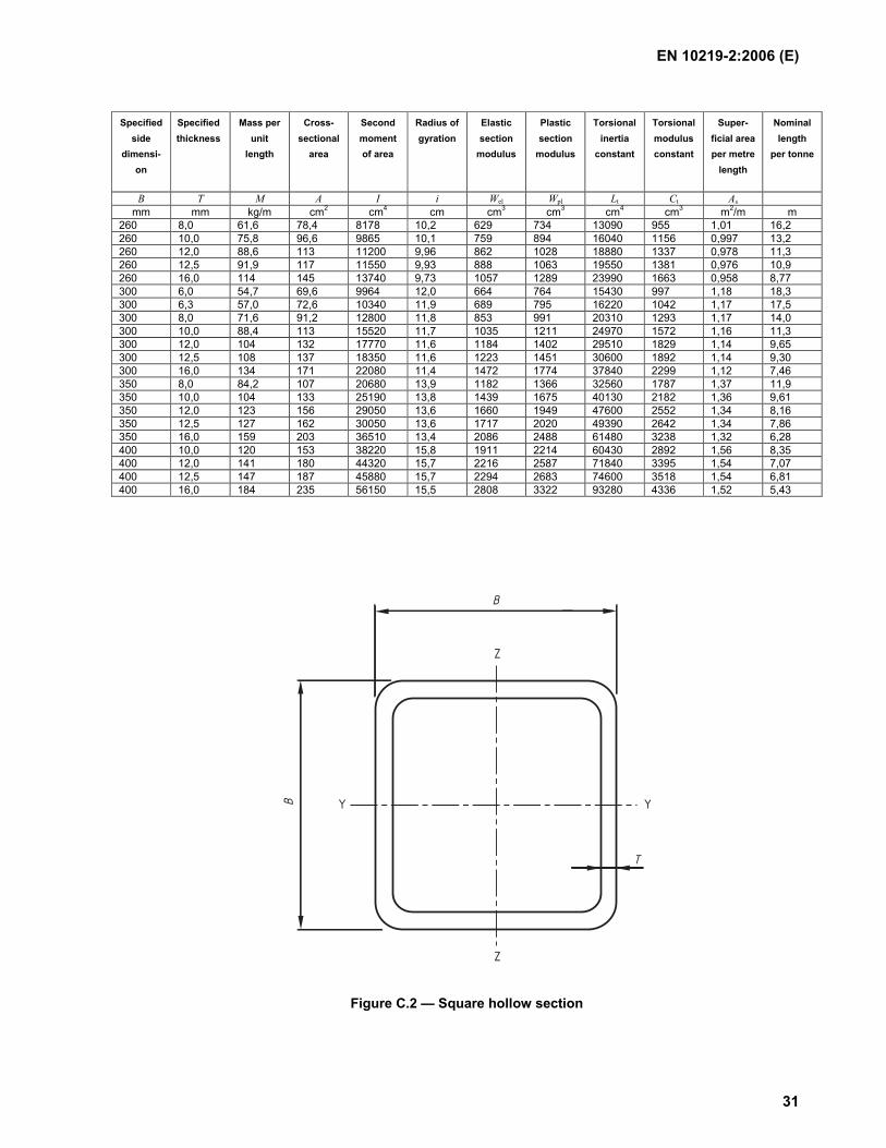
Table C.2 — Nominal dimensions and sectional properties of a limited range of square hollow sections (see Figure C.2)
Specified side
dimensi-on
Specified thickness
Mass per unit
length
Cross-sectional
area
Second moment of area
Radius of gyration
Elastic section
modulus
Plastic section
modulus
Torsional inertia
constant
Torsional modulus constant
Super- ficial area per metre
length
Nominal length
per tonne
B T M A I i Wel Wpl Lt Ct As mm mm kg/m cm2 cm4 cm cm3 cm3 cm4 cm3 m2/m m
20 2,0 1,05 1,34 0,692 0,720 0,692 0,877 1,21 1,06 0,0731 953 25 2,0 1,36 1,74 1,48 0,924 1,19 1,47 2,53 1,80 0,0931 733 25 2,5 1,64 2,09 1,69 0,899 1,35 1,71 2,97 2,07 0,0914 610 25 3,0 1,89 2,41 1,84 0,874 1,47 1,91 3,33 2,27 0,0897 529 30 2,0 1,68 2,14 2,72 1,13 1,81 2,21 4,54 2,75 0,113 596 30 2,5 2,03 2,59 3,16 1,10 2,10 2,61 5,40 3,20 0,111 492 30 3,0 2,36 3,01 3,50 1,08 2,34 2,96 6,15 3,58 0,110 423 40 2,0 2,31 2,94 6,94 1,54 3,47 4,13 11,3 5,23 0,153 434 40 2,5 2,82 3,59 8,22 1,51 4,11 4,97 13,6 6,21 0,151 355 40 3,0 3,30 4,21 9,32 1,49 4,66 5,72 15,8 7,07 0,150 303 40 4,0 4,20 5,35 11,1 1,44 5,54 7,01 19,4 8,48 0,146 238 50 2,0 2,93 3,74 14,1 1,95 5,66 6,66 22,6 8,51 0,193 341 50 2,5 3,60 4,59 16,9 1,92 6,78 8,07 27,5 10,2 0,191 278 50 3,0 4,25 5,41 19,5 1,90 7,79 9,39 32,1 11,8 0,190 236 50 4,0 5,45 6,95 23,7 1,85 9,49 11,7 40,4 14,4 0,186 183 50 5,0 6,56 8,36 27,0 1,80 10,8 13,7 47,5 16,6 0,183 152 60 2,0 3,56 4,54 25,1 2,35 8,38 9,79 39,8 12,6 0,233 281 60 2,5 4,39 5,59 30,3 2,33 10,1 11,9 48,7 15,2 0,231 228 60 3,0 5,19 6,61 35,1 2,31 11,7 14,0 57,1 17,7 0,230 193 60 4,0 6,71 8,55 43,6 2,26 14,5 17,6 72,6 22,0 0,226 149 60 5,0 8,13 10,4 50,5 2,21 16,8 20,9 86,4 25,6 0,223 123 60 6,0 9,45 12,0 56,1 2,16 18,7 23,7 98,4 28,6 0,219 106 60 6,3 9,55 12,2 54,4 2,11 18,1 23,4 100 28,8 0,213 105 70 2,5 5,17 6,59 49,4 2,74 14,1 16,5 78,5 21,2 0,271 193 70 3,0 6,13 7,81 57,5 2,71 16,4 19,4 92,4 24,7 0,270 163 70 4,0 7,97 10,1 72,1 2,67 20,6 24,8 119 31,1 0,266 126 70 5,0 9,70 12,4 84,6 2,62 24,2 29,6 142 36,7 0,263 103 70 6,0 11,3 14,4 95,2 2,57 27,2 33,8 163 41,4 0,259 88,3 70 6,3 11,5 14,7 93,8 2,53 26,8 33,8 168 42,1 0,253 86,7 80 3,0 7,07 9,01 87,8 3,12 22,0 25,8 140 33,0 0,310 141 80 4,0 9,22 11,7 111 3,07 27,8 33,1 180 41,8 0,306 108 80 5,0 11,3 14,4 131 3,03 32,9 39,7 218 49,7 0,303 88,7 80 6,0 13,2 16,8 149 2,98 37,3 45,8 252 56,6 0,299 75,7 80 6,3 13,5 17,2 149 2,94 37,1 46,1 261 57,9 0,293 74,0 80 8,0 16,4 20,8 168 2,84 42,1 53,9 307 66,6 0,286 61,1 90 3,0 8,01 10,2 127 3,53 28,3 33,0 201 42,5 0,350 125 90 4,0 10,5 13,3 162 3,48 36,0 42,6 261 54,2 0,346 95,4 90 5,0 12,8 16,4 193 3,43 42,9 51,4 316 64,7 0,343 77,9 90 6,0 15,1 19,2 220 3,39 49,0 59,5 368 74,2 0,339 66,2 90 6,3 15,5 19,7 221 3,35 49,1 60,3 382 76,2 0,333 64,6 90 8,0 18,9 24,0 255 3,25 56,6 71,3 456 88,8 0,326 53,0 100 3,0 8,96 11,4 177 3,94 35,4 41,2 279 53,2 0,390 112 100 4,0 11,7 14,9 226 3,89 45,3 53,3 362 68,1 0,386 85,2 100 5,0 14,4 18,4 271 3,84 54,2 64,6 441 81,7 0,383 69,4 100 6,0 17,0 21,6 311 3,79 62,3 75,1 514 94,1 0,379 58,9 100 6,3 17,5 22,2 314 3,76 62,8 76,4 536 97,0 0,373 57,3 100 8,0 21,4 27,2 366 3,67 73,2 91,1 645 114 0,366 46,8 100 10,0 25,6 32,6 411 3,55 82,2 105 750 130 0,357 39,1 100 12,0 28,3 36,1 408 3,36 81,6 110 794 136 0,338 35,3 100 12,5 29,1 37,0 410 3,33 82,1 111 804 137 0,336 34,4 120 3,0 10,8 13,8 312 4,76 52,1 60,2 488 78,2 0,470 92,3 120 4,0 14,2 18,1 402 4,71 67,0 78,3 637 101 0,466 70,2 120 5,0 17,5 22,4 485 4,66 80,9 95,4 778 122 0,463 57,0 120 6,0 20,7 26,4 562 4,61 93,7 112 913 141 0,459 48,2 120 6,3 21,4 27,3 572 4,58 95,3 114 955 146 0,453 46,7 120 8,0 26,4 33,6 677 4,49 113 138 1163 175 0,446 37,9 120 10,0 31,8 40,6 777 4,38 129 162 1376 203 0,437 31,4 120 12,0 35,8 45,7 806 4,20 134 174 1518 219 0,418 27,9 120 12,5 36,9 47,0 817 4,17 136 178 1551 223 0,416 27,1

EN 10219-2:2006 (E)
30
Specified side
dimensi-on
Specified thickness
Mass per unit
length
Cross-sectional
area
Second moment of area
Radius of gyration
Elastic section
modulus
Plastic section
modulus
Torsional inertia
constant
Torsional modulus constant
Super- ficial area per metre
length
Nominal length
per tonne
B T M A I i Wel Wpl Lt Ct As mm mm kg/m cm2 cm4 cm cm3 cm3 cm4 cm3 m2/m m
140 4,0 16,8 21,3 652 5,52 93,1 108 1023 140 0,546 59,7 140 5,0 20,7 26,4 791 5,48 113 132 1256 170 0,543 48,3 140 6,0 24,5 31,2 920 5,43 131 155 1479 198 0,539 40,8 140 6,3 25,4 32,3 941 5,39 134 160 1550 205 0,533 39,4 140 8,0 31,4 40,0 1127 5,30 161 194 1901 248 0,526 31,8 140 10,0 38,1 48,6 1312 5,20 187 230 2274 291 0,517 26,2 140 12,0 43,4 55,3 1398 5,03 200 253 2567 322 0,498 23,1 140 12,5 44,8 57,0 1425 5,00 204 259 2634 329 0,496 22,3 150 4,0 18,0 22,9 808 5,93 108 125 1265 162 0,586 55,5 150 5,0 22,3 28,4 982 5,89 131 153 1554 197 0,583 44,9 150 6,0 26,4 33,6 1146 5,84 153 180 1833 230 0,579 37,9 150 6,3 27,4 34,8 1174 5,80 156 185 1922 239 0,573 36,6 150 8,0 33,9 43,2 1412 5,71 188 226 2364 289 0,566 29,5 150 10,0 41,3 52,6 1653 5,61 220 269 2839 341 0,557 24,2 150 12,0 47,1 60,1 1780 5,44 237 298 3231 380 0,538 21,2 150 12,5 48,7 62,0 1817 5,41 242 306 3321 389 0,536 20,5 150 16,0 58,7 74,8 2009 5,18 268 351 3830 440 0,518 17,0 160 4,0 19,3 24,5 987 6,34 123 143 1541 185 0,626 51,9 160 5,0 23,8 30,4 1202 6,29 150 175 1896 226 0,623 42,0 160 6,0 28,3 36,0 1405 6,25 176 206 2239 264 0,619 35,4 160 6,3 29,3 37,4 1442 6,21 180 213 2349 275 0,613 34,1 160 8,0 36,5 46,4 1741 6,12 218 260 2897 334 0,606 27,4 160 10,0 44,4 56,6 2048 6,02 256 311 3490 395 0,597 22,5 160 12,0 50,9 64,9 2224 5,86 278 346 3997 443 0,578 19,6 160 12,5 52,6 67,0 2275 5,83 284 356 4114 455 0,576 19,0 160 16,0 63,7 81,2 2546 5,60 318 413 4799 520 0,558 15,7 180 4,0 21,8 27,7 1422 7,16 158 182 2210 237 0,706 45,9 180 5,0 27,0 34,4 1737 7,11 193 224 2724 290 0,703 37,1 180 6,0 32,1 40,8 2037 7,06 226 264 3223 340 0,699 31,2 180 6,3 33,3 42,4 2096 7,03 233 273 3383 354 0,693 30,0 180 8,0 41,5 52,8 2546 6,94 283 336 4189 432 0,686 24,1 180 10,0 50,7 64,6 3017 6,84 335 404 5074 515 0,677 19,7 180 12,0 58,5 74,5 3322 6,68 369 454 5865 584 0,658 17,1 180 12,5 60,5 77,0 3406 6,65 378 467 6050 600 0,656 16,5 180 16,0 73,8 94,0 3887 6,43 432 550 7178 698 0,638 13,6 200 4,0 24,3 30,9 1968 7,97 197 226 3049 295 0,786 41,2 200 5,0 30,1 38,4 2410 7,93 241 279 3763 362 0,783 33,2 200 6,0 35,8 45,6 2833 7,88 283 330 4459 426 0,779 27,9 200 6,3 37,2 47,4 2922 7,85 292 341 4682 444 0,773 26,8 200 8,0 46,5 59,2 3566 7,76 357 421 5815 544 0,766 21,5 200 10,0 57,0 72,6 4251 7,65 425 508 7072 651 0,757 17,6 200 12,0 66,0 84,1 4730 7,50 473 576 8230 743 0,738 15,2 200 12,5 68,3 87,0 4859 7,47 486 594 8502 765 0,736 14,6 200 16,0 83,8 107 5625 7,26 562 706 10210 901 0,718 11,9 220 5,0 33,2 42,4 3238 8,74 294 340 5038 442 0,863 30,1 220 6,0 39,6 50,4 3813 8,70 347 402 5976 521 0,859 25,3 220 6,3 41,2 52,5 3940 8,66 358 417 6277 543 0,853 24,3 220 8,0 51,5 65,6 4828 8,58 439 516 7815 668 0,846 19,4 220 10,0 63,2 80,6 5782 8,47 526 625 9533 804 0,837 15,8 220 12,0 73,5 93,7 6487 8,32 590 712 11150 922 0,818 13,6 220 12,5 76,2 97,0 6674 8,29 607 735 11530 951 0,816 13,1 220 16,0 93,9 120 7812 8,08 710 881 13970 1129 0,798 10,7 250 5,0 38,0 48,4 4805 9,97 384 442 7443 577 0,983 26,3 250 6,0 45,2 57,6 5672 9,92 454 524 8843 681 0,979 22,1 250 6,3 47,1 60,0 5873 9,89 470 544 9290 711 0,973 21,2 250 8,0 59,1 75,2 7229 9,80 578 676 11600 878 0,966 16,9 250 10,0 72,7 92,6 8707 9,70 697 822 14200 1062 0,957 13,8 250 12,0 84,8 108 9859 9,55 789 944 16690 1226 0,938 11,8 250 12,5 88,0 112 10160 9,52 813 975 17280 1266 0,936 11,4 250 16,0 109 139 12050 9,32 964 1180 21150 1520 0,918 9,18 260 6,0 47,1 60,0 6405 10,3 493 569 9970 739 1,02 21,2 260 6,3 49,1 62,6 6635 10,3 510 591 10480 772 1,01 20,4
EN 10219-2:2006 (E)
31
Specified side
dimensi-on
Specified thickness
Mass per unit
length
Cross-sectional
area
Second moment of area
Radius of gyration
Elastic section
modulus
Plastic section
modulus
Torsional inertia
constant
Torsional modulus constant
Super- ficial area per metre
length
Nominal length
per tonne
B T M A I i Wel Wpl Lt Ct As mm mm kg/m cm2 cm4 cm cm3 cm3 cm4 cm3 m2/m m
260 8,0 61,6 78,4 8178 10,2 629 734 13090 955 1,01 16,2 260 10,0 75,8 96,6 9865 10,1 759 894 16040 1156 0,997 13,2 260 12,0 88,6 113 11200 9,96 862 1028 18880 1337 0,978 11,3 260 12,5 91,9 117 11550 9,93 888 1063 19550 1381 0,976 10,9 260 16,0 114 145 13740 9,73 1057 1289 23990 1663 0,958 8,77 300 6,0 54,7 69,6 9964 12,0 664 764 15430 997 1,18 18,3 300 6,3 57,0 72,6 10340 11,9 689 795 16220 1042 1,17 17,5 300 8,0 71,6 91,2 12800 11,8 853 991 20310 1293 1,17 14,0 300 10,0 88,4 113 15520 11,7 1035 1211 24970 1572 1,16 11,3 300 12,0 104 132 17770 11,6 1184 1402 29510 1829 1,14 9,65 300 12,5 108 137 18350 11,6 1223 1451 30600 1892 1,14 9,30 300 16,0 134 171 22080 11,4 1472 1774 37840 2299 1,12 7,46 350 8,0 84,2 107 20680 13,9 1182 1366 32560 1787 1,37 11,9 350 10,0 104 133 25190 13,8 1439 1675 40130 2182 1,36 9,61 350 12,0 123 156 29050 13,6 1660 1949 47600 2552 1,34 8,16 350 12,5 127 162 30050 13,6 1717 2020 49390 2642 1,34 7,86 350 16,0 159 203 36510 13,4 2086 2488 61480 3238 1,32 6,28 400 10,0 120 153 38220 15,8 1911 2214 60430 2892 1,56 8,35 400 12,0 141 180 44320 15,7 2216 2587 71840 3395 1,54 7,07 400 12,5 147 187 45880 15,7 2294 2683 74600 3518 1,54 6,81 400 16,0 184 235 56150 15,5 2808 3322 93280 4336 1,52 5,43
Z
B
B
T
Z
YY
Figure C.2 — Square hollow section
EN 10219-2:2006 (E)
32
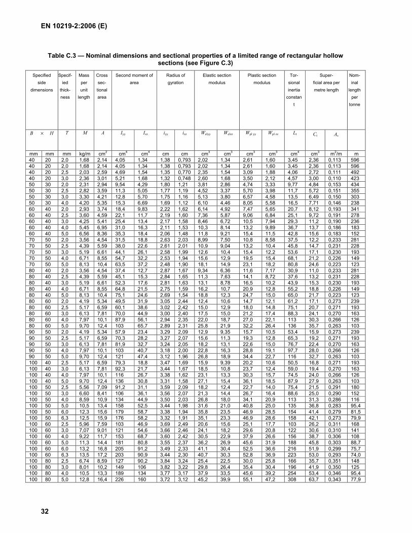
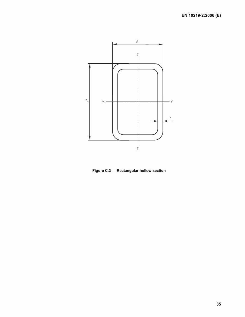
Table C.3 — Nominal dimensions and sectional properties of a limited range of rectangular hollow sections (see Figure C.3)
Specified side
dimensions
Specif-ied
thick-ness
Mass per unit
length
Crosssec-tional area
Second moment of area
Radius of gyration
Elastic section modulus
Plastic section modulus
Tor-sional inertia
constant
Super- ficial area per metre length
Nom-inal
length per
tonne
B × H T M A Iyy Izz iyy izz Welyy Welzz Wpl yy Wpl zz Lt
Ct As
mm mm mm kg/m cm2 cm4 cm4 cm cm cm3 cm3 cm3 cm3 cm4 cm3 m2/m m 40 20 2,0 1,68 2,14 4,05 1,34 1,38 0,793 2,02 1,34 2,61 1,60 3,45 2,36 0,113 596 40 20 2,0 1,68 2,14 4,05 1,34 1,38 0,793 2,02 1,34 2,61 1,60 3,45 2,36 0,113 596 40 20 2,5 2,03 2,59 4,69 1,54 1,35 0,770 2,35 1,54 3,09 1,88 4,06 2,72 0,111 492 40 20 3,0 2,36 3,01 5,21 1,68 1,32 0,748 2,60 1,68 3,50 2,12 4,57 3,00 0,110 423 50 30 2,0 2,31 2,94 9,54 4,29 1,80 1,21 3,81 2,86 4,74 3,33 9,77 4,84 0,153 434 50 30 2,5 2,82 3,59 11,3 5,05 1,77 1,19 4,52 3,37 5,70 3,98 11,7 5,72 0,151 355 50 30 3,0 3,30 4,21 12,8 5,70 1,75 1,16 5,13 3,80 6,57 4,58 13,5 6,49 0,150 303 50 30 4,0 4,20 5,35 15,3 6,69 1,69 1,12 6,10 4,46 8,05 5,58 16,5 7,71 0,146 238 60 40 2,0 2,93 3,74 18,4 9,83 2,22 1,62 6,14 4,92 7,47 5,65 20,7 8,12 0,193 341 60 40 2,5 3,60 4,59 22,1 11,7 2,19 1,60 7,36 5,87 9,06 6,84 25,1 9,72 0,191 278 60 40 3,0 4,25 5,41 25,4 13,4 2,17 1,58 8,46 6,72 10,5 7,94 29,3 11,2 0,190 236 60 40 4,0 5,45 6,95 31,0 16,3 2,11 1,53 10,3 8,14 13,2 9,89 36,7 13,7 0,186 183 60 40 5,0 6,56 8,36 35,3 18,4 2,06 1,48 11,8 9,21 15,4 11,5 42,8 15,6 0,183 152 70 50 2,0 3,56 4,54 31,5 18,8 2,63 2,03 8,99 7,50 10,8 8,58 37,5 12,2 0,233 281 70 50 2,5 4,39 5,59 38,0 22,6 2,61 2,01 10,9 9,04 13,2 10,4 45,8 14,7 0,231 228 70 50 3,0 5,19 6,61 44,1 26,1 2,58 1,99 12,6 10,4 15,4 12,2 53,6 17,1 0,230 193 70 50 4,0 6,71 8,55 54,7 32,2 2,53 1,94 15,6 12,9 19,5 15,4 68,1 21,2 0,226 149 70 50 5,0 8,13 10,4 63,5 37,2 2,48 1,90 18,1 14,9 23,1 18,2 80,8 24,6 0,223 123 80 40 2,0 3,56 4,54 37,4 12,7 2,87 1,67 9,34 6,36 11,6 7,17 30,9 11,0 0,233 281 80 40 2,5 4,39 5,59 45,1 15,3 2,84 1,65 11,3 7,63 14,1 8,72 37,6 13,2 0,231 228 80 40 3,0 5,19 6,61 52,3 17,6 2,81 1,63 13,1 8,78 16,5 10,2 43,9 15,3 0,230 193 80 40 4,0 6,71 8,55 64,8 21,5 2,75 1,59 16,2 10,7 20,9 12,8 55,2 18,8 0,226 149 80 40 5,0 8,13 10,4 75,1 24,6 2,69 1,54 18,8 12,3 24,7 15,0 65,0 21,7 0,223 123 80 60 2,0 4,19 5,34 49,5 31,9 3,05 2,44 12,4 10,6 14,7 12,1 61,2 17,1 0,273 239 80 60 2,5 5,17 6,59 60,1 38,6 3,02 2,42 15,0 12,9 18,0 14,8 75,1 20,7 0,271 193 80 60 3,0 6,13 7,81 70,0 44,9 3,00 2,40 17,5 15,0 21,2 17,4 88,3 24,1 0,270 163 80 60 4,0 7,97 10,1 87,9 56,1 2,94 2,35 22,0 18,7 27,0 22,1 113 30,3 0,266 126 80 60 5,0 9,70 12,4 103 65,7 2,89 2,31 25,8 21,9 32,2 26,4 136 35,7 0,263 103 90 50 2,0 4,19 5,34 57,9 23,4 3,29 2,09 12,9 9,35 15,7 10,5 53,4 15,9 0,273 239 90 50 2,5 5,17 6,59 70,3 28,2 3,27 2,07 15,6 11,3 19,3 12,8 65,3 19,2 0,271 193 90 50 3,0 6,13 7,81 81,9 32,7 3,24 2,05 18,2 13,1 22,6 15,0 76,7 22,4 0,270 163 90 50 4,0 7,97 10,1 103 40,7 3,18 2,00 22,8 16,3 28,8 19,1 97,7 28,0 0,266 126 90 50 5,0 9,70 12,4 121 47,4 3,12 1,96 26,8 18,9 34,4 22,7 116 32,7 0,263 103 100 40 2,5 5,17 6,59 79,3 18,8 3,47 1,69 15,9 9,39 20,2 10,6 50,5 16,8 0,271 193 100 40 3,0 6,13 7,81 92,3 21,7 3,44 1,67 18,5 10,8 23,7 12,4 59,0 19,4 0,270 163 100 40 4,0 7,97 10,1 116 26,7 3,38 1,62 23,1 13,3 30,3 15,7 74,5 24,0 0,266 126 100 40 5,0 9,70 12,4 136 30,8 3,31 1,58 27,1 15,4 36,1 18,5 87,9 27,9 0,263 103 100 50 2,5 5,56 7,09 91,2 31,1 3,59 2,09 18,2 12,4 22,7 14,0 75,4 21,5 0,291 180 100 50 3,0 6,60 8,41 106 36,1 3,56 2,07 21,3 14,4 26,7 16,4 88,6 25,0 0,290 152 100 50 4,0 8,59 10,9 134 44,9 3,50 2,03 26,8 18,0 34,1 20,9 113 31,3 0,286 116 100 50 5,0 10,5 13,4 158 52,5 3,44 1,98 31,6 21,0 40,8 25,0 135 36,8 0,283 95,4 100 50 6,0 12,3 15,6 179 58,7 3,38 1,94 35,8 23,5 46,9 28,5 154 41,4 0,279 81,5 100 50 6,3 12,5 15,9 176 58,2 3,32 1,91 35,1 23,3 46,9 28,6 158 42,1 0,273 79,9 100 60 2,5 5,96 7,59 103 46,9 3,69 2,49 20,6 15,6 25,1 17,7 103 26,2 0,311 168 100 60 3,0 7,07 9,01 121 54,6 3,66 2,46 24,1 18,2 29,6 20,8 122 30,6 0,310 141 100 60 4,0 9,22 11,7 153 68,7 3,60 2,42 30,5 22,9 37,9 26,6 156 38,7 0,306 108 100 60 5,0 11,3 14,4 181 80,8 3,55 2,37 36,2 26,9 45,6 31,9 188 45,8 0,303 88,7 100 60 6,0 13,2 16,8 205 91,2 3,49 2,33 41,1 30,4 52,5 36,6 216 51,9 0,299 75,7 100 60 6,3 13,5 17,2 203 90,9 3,44 2,30 40,7 30,3 52,8 36,9 223 53,0 0,293 74,0 100 80 2,5 6,74 8,59 127 90,2 3,84 3,24 25,4 22,5 30,0 25,8 166 35,7 0,351 148 100 80 3,0 8,01 10,2 149 106 3,82 3,22 29,8 26,4 35,4 30,4 196 41,9 0,350 125 100 80 4,0 10,5 13,3 189 134 3,77 3,17 37,9 33,5 45,6 39,2 254 53,4 0,346 95,4 100 80 5,0 12,8 16,4 226 160 3,72 3,12 45,2 39,9 55,1 47,2 308 63,7 0,343 77,9

EN 10219-2:2006 (E)
33
Specified side
dimensions
Specif-ied
thick-ness
Mass per unit
length
Crosssec-tional area
Second moment of area
Radius of gyration
Elastic section modulus
Plastic section modulus
Tor-sional inertia
constant
Super- ficial area per metre length
Nom-inal
length per
tonne
B × H T M A Iyy Izz iyy izz Welyy Welzz Wpl yy Wpl zz Lt
Ct As
mm mm mm kg/m cm2 cm4 cm4 cm cm cm3 cm3 cm3 cm3 cm4 cm3 m2/m m 100 80 6,0 15,1 19,2 258 182 3,67 3,08 51,7 45,5 63,8 54,7 357 73,0 0,339 66,2 100 80 6,3 15,5 19,7 259 183 3,62 3,04 51,8 45,7 64,6 55,4 371 75,0 0,333 64,6 120 60 2,5 6,74 8,59 161 55,2 4,33 2,53 26,9 18,4 33,2 20,6 133 31,7 0,351 148 120 60 3,0 8,01 10,2 189 64,4 4,30 2,51 31,5 21,5 39,2 24,2 156 37,1 0,350 125 120 60 4,0 10,5 13,3 241 81,2 4,25 2,47 40,1 27,1 50,5 31,1 201 47,0 0,346 95,4 120 60 5,0 12,8 16,4 287 96,0 4,19 2,42 47,8 32,0 60,9 37,4 242 55,8 0,343 77,9 120 60 6,0 15,1 19,2 328 109 4,13 2,38 54,7 36,3 70,6 43,1 280 63,6 0,339 66,2 120 60 6,3 15,5 19,7 327 109 4,07 2,35 54,5 36,4 71,2 43,7 289 65,1 0,333 64,6 120 60 8,0 18,9 24,0 375 124 3,95 2,27 62,6 41,3 84,1 51,3 340 75,0 0,326 53,0 120 80 3,0 8,96 11,4 230 123 4,49 3,29 38,4 30,9 46,2 35,0 255 50,8 0,390 112 120 80 4,0 11,7 14,9 295 157 4,44 3,24 49,1 39,3 59,8 45,2 331 64,9 0,386 85,2 120 80 5,0 14,4 18,4 353 188 4,39 3,20 58,9 46,9 72,4 54,7 402 77,8 0,383 69,4 120 80 6,0 17,0 21,6 406 215 4,33 3,15 67,7 53,8 84,3 63,5 469 89,4 0,379 58,9 120 80 6,3 17,5 22,2 408 217 4,28 3,12 68,1 54,3 85,6 64,7 488 92,1 0,373 57,3 120 80 8,0 21,4 27,2 476 252 4,18 3,04 79,3 62,9 102 76,9 584 108 0,366 46,8 140 80 4,0 13,0 16,5 430 180 5,10 3,30 61,4 45,1 75,5 51,3 412 76,5 0,426 77,0 140 80 5,0 16,0 20,4 517 216 5,04 3,26 73,9 54,0 91,8 62,2 501 91,8 0,423 62,6 140 80 6,0 18,9 24,0 597 248 4,98 3,21 85,3 62,0 107 72,4 584 106 0,419 53,0 140 80 6,3 19,4 24,8 603 251 4,93 3,19 86,1 62,9 109 74,0 609 109 0,413 51,4 140 80 8,0 23,9 30,4 708 293 4,82 3,10 101 73,3 131 88,4 731 129 0,406 41,8 150 100 4,0 14,9 18,9 595 319 5,60 4,10 79,3 63,7 95,7 72,5 662 105 0,486 67,2 150 100 5,0 18,3 23,4 719 384 5,55 4,05 95,9 76,8 117 88,3 809 127 0,483 54,5 150 100 6,0 21,7 27,6 835 444 5,50 4,01 111 88,8 137 103 948 147 0,479 46,1 150 100 6,3 22,4 28,5 848 453 5,45 3,98 113 90,5 140 106 992 152 0,473 44,6 150 100 8,0 27,7 35,2 1008 536 5,35 3,90 134 107 169 128 1206 182 0,466 36,1 150 100 10,0 33,4 42,6 1162 614 5,22 3,80 155 123 199 150 1426 211 0,457 29,9 150 100 12,0 37,7 48,1 1207 642 5,01 3,65 161 128 215 163 1573 229 0,438 26,5 150 100 12,5 38,9 49,5 1225 651 4,97 3,63 163 130 220 166 1606 233 0,436 25,7 160 80 4,0 14,2 18,1 598 204 5,74 3,35 74,7 50,9 92,9 57,4 494 88,0 0,466 70,2 160 80 5,0 17,5 22,4 722 244 5,68 3,30 90,2 61,0 113 69,7 601 106 0,463 57,0 160 80 6,0 20,7 26,4 836 281 5,62 3,26 105 70,2 132 81,3 702 122 0,459 48,2 160 80 6,3 21,4 27,3 846 286 5,57 3,24 106 71,4 135 83,3 732 126 0,453 46,7 160 80 8,0 26,4 33,6 1001 335 5,46 3,16 125 83,7 163 100 882 150 0,446 37,9 160 80 10,0 31,8 40,6 1146 380 5,32 3,06 143 95,0 191 117 1031 172 0,437 31,4 160 80 12,0 35,8 45,7 1171 391 5,06 2,93 146 97,8 204 125 1111 183 0,418 27,9 160 80 12,5 36,9 47,0 1185 396 5,02 2,90 148 98,9 208 127 1129 185 0,416 27,1 180 100 4,0 16,8 21,3 926 374 6,59 4,18 103 74,8 126 84,0 854 127 0,546 59,7 180 100 5,0 20,7 26,4 1124 452 6,53 4,14 125 90,4 154 103 1045 154 0,543 48,3 180 100 6,0 24,5 31,2 1310 524 6,48 4,10 146 105 181 120 1227 179 0,539 40,8 180 100 6,3 25,4 32,3 1335 536 6,43 4,07 148 107 186 124 1283 185 0,533 39,4 180 100 8,0 31,4 40,0 1598 637 6,32 3,99 178 127 226 150 1565 222 0,526 31,8 180 100 10,0 38,1 48,6 1859 736 6,19 3,89 207 147 268 177 1859 260 0,517 26,2 180 100 12,0 43,4 55,3 1965 782 5,96 3,76 218 156 292 194 2073 285 0,498 23,1 180 100 12,5 44,8 57,0 2001 796 5,92 3,74 222 159 300 199 2122 290 0,496 22,3 200 100 4,0 18,0 22,9 1200 411 7,23 4,23 120 82,2 148 91,7 985 142 0,586 55,5 200 100 5,0 22,3 28,4 1459 497 7,17 4,19 146 99,4 181 112 1206 172 0,583 44,9 200 100 6,0 26,4 33,6 1703 577 7,12 4,14 170 115 213 132 1417 200 0,579 37,9 200 100 6,3 27,4 34,8 1739 591 7,06 4,12 174 118 219 135 1483 208 0,573 36,6 200 100 8,0 33,9 43,2 2091 705 6,95 4,04 209 141 267 165 1811 250 0,566 29,5 200 100 10,0 41,3 52,6 2444 818 6,82 3,94 244 164 318 195 2154 292 0,557 24,2 200 100 12,0 47,1 60,1 2607 876 6,59 3,82 261 175 350 215 2414 322 0,538 21,2 200 100 12,5 48,7 62,0 2659 892 6,55 3,79 266 178 359 221 2474 329 0,536 20,5 200 120 4,0 19,3 24,5 1353 618 7,43 5,02 135 103 164 115 1345 172 0,626 51,9 200 120 5,0 23,8 30,4 1649 750 7,37 4,97 165 125 201 141 1652 210 0,623 42,0 200 120 6,0 28,3 36,0 1929 874 7,32 4,93 193 146 237 166 1947 245 0,619 35,4 200 120 6,3 29,3 37,4 1976 898 7,27 4,90 198 150 244 172 2040 255 0,613 34,1

EN 10219-2:2006 (E)
34
Specified side
dimensions
Specif-ied
thick-ness
Mass per unit
length
Crosssec-tional area
Second moment of area
Radius of gyration
Elastic section modulus
Plastic section modulus
Tor-sional inertia
constant
Super- ficial area per metre length
Nom-inal
length per
tonne
B × H T M A Iyy Izz iyy izz Welyy Welzz Wpl yy Wpl zz Lt
Ct As
mm mm mm kg/m cm2 cm4 cm4 cm cm cm3 cm3 cm3 cm3 cm4 cm3 m2/m m 200 120 8,0 36,5 46,4 2386 1079 7,17 4,82 239 180 298 209 2507 308 0,606 27,4 200 120 10,0 44,4 56,6 2806 1262 7,04 4,72 281 210 356 250 3007 364 0,597 22,5 200 120 12,0 50,9 64,9 3031 1368 6,84 4,59 303 228 395 278 3419 406 0,578 19,6 200 120 12,5 52,6 67,0 3099 1397 6,80 4,57 310 233 406 285 3514 416 0,576 19,0 250 150 5,0 30,1 38,4 3304 1508 9,28 6,27 264 201 320 225 3285 337 0,783 33,2 250 150 6,0 35,8 45,6 3886 1768 9,23 6,23 311 236 378 266 3886 396 0,779 27,9 250 150 6,3 37,2 47,4 4001 1825 9,18 6,20 320 243 391 276 4078 412 0,773 26,8 250 150 8,0 46,5 59,2 4886 2219 9,08 6,12 391 296 482 340 5050 504 0,766 21,5 250 150 10,0 57,0 72,6 5825 2634 8,96 6,02 466 351 582 409 6121 602 0,757 17,6 250 150 12,0 66,0 84,1 6458 2925 8,77 5,90 517 390 658 463 7088 684 0,738 15,2 250 150 12,5 68,3 87,0 6633 3002 8,73 5,87 531 400 678 477 7315 704 0,736 14,6 250 150 16,0 83,8 106,8 7660 3453 8,47 5,69 613 460 805 566 8713 823 0,718 11,9 260 180 5,0 33,2 42,4 4121 2350 9,86 7,45 317 261 377 294 4695 426 0,863 30,1 260 180 6,3 41,2 52,5 5013 2856 9,77 7,38 386 317 463 361 5844 523 0,853 24,3 260 180 8,0 51,5 65,6 6145 3493 9,68 7,29 473 388 573 446 7267 642 0,846 19,4 260 180 10,0 63,2 80,6 7363 4174 9,56 7,20 566 464 694 540 8850 772 0,837 15,8 260 180 12,0 73,5 93,7 8245 4679 9,38 7,07 634 520 790 615 10330 884 0,818 13,6 260 180 12,5 76,2 97,0 8482 4812 9,35 7,04 652 535 815 635 10680 911 0,816 13,1 260 180 16,0 93,9 120 9923 5614 9,11 6,85 763 624 977 759 12890 1079 0,798 10,7 300 100 6,0 35,8 45,6 4777 842 10,2 4,30 318 168 411 188 2403 306 0,779 27,9 300 100 6,3 37,2 47,4 4907 868 10,2 4,28 327 174 425 194 2515 318 0,773 26,8 300 100 8,0 46,5 59,2 5978 1045 10,0 4,20 399 209 523 238 3080 385 0,766 21,5 300 100 10,0 57,0 72,6 7106 1224 9,90 4,11 474 245 631 285 3681 455 0,757 17,6 300 100 12,0 66,0 84,1 7808 1343 9,64 4,00 521 269 710 321 4177 508 0,738 15,2 300 100 12,5 68,3 87,0 8010 1374 9,59 3,97 534 275 732 330 4292 521 0,736 14,6 300 100 16,0 83,8 107 9157 1543 9,26 3,80 610 309 865 386 4939 592 0,718 11,9 300 150 6,0 40,5 51,6 6074 2080 10,8 6,35 405 277 500 309 4988 479 0,879 24,7 300 150 6,3 42,2 53,7 6266 2150 10,8 6,32 418 287 517 321 5234 499 0,873 23,7 300 150 8,0 52,8 67,2 7684 2623 10,7 6,25 512 350 640 396 6491 612 0,866 18,9 300 150 10,0 64,8 82,6 9209 3125 10,6 6,15 614 417 776 479 7879 733 0,857 15,4 300 150 12,0 75,4 96,1 10300 3498 10,4 6,03 687 466 883 546 9153 837 0,838 13,3 300 150 12,5 78,1 99,5 10590 3595 10,3 6,01 706 479 912 563 9452 862 0,836 12,8 300 150 16,0 96,4 123 12390 4174 10,0 5,83 826 557 1092 673 11330 1015 0,818 10,4 300 200 6,0 45,2 57,6 7370 3962 11,3 8,29 491 396 588 446 8115 651 0,979 22,1 300 200 6,3 47,1 60,0 7624 4104 11,3 8,27 508 410 610 463 8524 680 0,973 21,2 300 200 8,0 59,1 75,2 9389 5042 11,2 8,19 626 504 757 574 10630 838 0,966 16,9 300 200 10,0 72,7 92,6 11310 6058 11,1 8,09 754 606 921 698 12990 1012 0,957 13,8 300 200 12,0 84,8 108 12790 6854 10,9 7,96 853 685 1056 801 15240 1167 0,938 11,8 300 200 12,5 88,0 112 13180 7060 10,8 7,94 879 706 1091 828 15770 1204 0,936 11,4 300 200 16,0 109 139 15620 8340 10,6 7,75 1041 834 1319 1000 19220 1442 0,918 9,18 350 250 6,0 54,7 69,6 12460 7458 13,4 10,3 712 597 843 671 14550 967 1,18 18,3 350 250 6,3 57,0 72,6 12920 7744 13,3 10,3 738 620 876 698 15290 1010 1,17 17,5 350 250 8,0 71,6 91,2 16000 9573 13,2 10,2 914 766 1092 869 19140 1253 1,17 14,0 350 250 10,0 88,4 113 19410 11590 13,1 10,1 1109 927 1335 1062 23500 1522 1,16 11,3 350 250 12,0 104 132 22200 13260 13,0 10,0 1268 1061 1544 1229 27750 1770 1,14 9,65 350 250 12,5 108 137 22920 13690 12,9 9,99 1310 1095 1598 1272 28770 1830 1,14 9,30 350 250 16,0 134 171 27580 16430 12,7 9,81 1576 1315 1954 1554 35500 2220 1,12 7,46 400 200 8,0 71,6 91,2 18970 6517 14,4 8,45 949 652 1173 728 15820 1133 1,17 14,0 400 200 12,5 108 137 27100 9260 14,1 8,22 1355 926 1714 1062 23600 1644 1,14 9,30 400 200 16,0 134 171 32550 11060 13,8 8,05 1627 1106 2093 1294 28930 1984 1,12 7,46 400 300 8,0 84,2 107 25120 16210 15,3 12,3 1256 1081 1487 1224 31180 1747 1,37 11,9 400 300 10,0 104 133 30610 19730 15,2 12,2 1530 1315 1824 1501 38410 2132 1,36 9,61 400 300 12,0 123 156 35280 22750 15,0 12,1 1764 1516 2122 1747 45530 2492 1,34 8,16 400 300 12,5 127 162 36490 23520 15,0 12,0 1824 1568 2198 1810 47240 2580 1,34 7,86 400 300 16,0 159 203 44350 28540 14,8 11,9 2218 1902 2708 2228 58730 3159 1,32 6,28
EN 10219-2:2006 (E)
35
B
T
H Y
Z
Z
Y
Figure C.3 — Rectangular hollow section

EN 10219-2:2006 (E)
36
Bibliography
ENV 1993-1-6, Eurocode 3: Design of steel structures - Part 1-6: General rules - Supplementary rules for the shell structures
ENV 1993-5, Eurocode 3: Design of steel structures - Part 5: Piling

blank

BS EN 10219-2:2006
BSI
389 Chiswick High Road
London
W4 4AL
BSI — British Standards InstitutionBSI is the independent national body responsible for preparing British Standards. It presents the UK view on standards in Europe and at the international level. It is incorporated by Royal Charter.
Revisions
British Standards are updated by amendment or revision. Users of British Standards should make sure that they possess the latest amendments or editions.
It is the constant aim of BSI to improve the quality of our products and services. We would be grateful if anyone finding an inaccuracy or ambiguity while using this British Standard would inform the Secretary of the technical committee responsible, the identity of which can be found on the inside front cover. Tel: +44 (0)20 8996 9000. Fax: +44 (0)20 8996 7400.
BSI offers members an individual updating service called PLUS which ensures that subscribers automatically receive the latest editions of standards.
Buying standards
Orders for all BSI, international and foreign standards publications should be addressed to Customer Services. Tel: +44 (0)20 8996 9001. Fax: +44 (0)20 8996 7001. Email: [email protected]. Standards are also available from the BSI website at http://www.bsi-global.com.
In response to orders for international standards, it is BSI policy to supply the BSI implementation of those that have been published as British Standards, unless otherwise requested.
Information on standards
BSI provides a wide range of information on national, European and international standards through its Library and its Technical Help to Exporters Service. Various BSI electronic information services are also available which give details on all its products and services. Contact the Information Centre. Tel: +44 (0)20 8996 7111. Fax: +44 (0)20 8996 7048. Email: [email protected].
Subscribing members of BSI are kept up to date with standards developments and receive substantial discounts on the purchase price of standards. For details of these and other benefits contact Membership Administration. Tel: +44 (0)20 8996 7002. Fax: +44 (0)20 8996 7001. Email: [email protected].
Information regarding online access to British Standards via British Standards Online can be found at http://www.bsi-global.com/bsonline.
Further information about BSI is available on the BSI website at http://www.bsi-global.com.
Copyright
Copyright subsists in all BSI publications. BSI also holds the copyright, in the UK, of the publications of the international standardization bodies. Except as permitted under the Copyright, Designs and Patents Act 1988 no extract may be reproduced, stored in a retrieval system or transmitted in any form or by any means – electronic, photocopying, recording or otherwise – without prior written permission from BSI.
This does not preclude the free use, in the course of implementing the standard, of necessary details such as symbols, and size, type or grade designations. If these details are to be used for any other purpose than implementation then the prior written permission of BSI must be obtained.
Details and advice can be obtained from the Copyright & Licensing Manager. Tel: +44 (0)20 8996 7070. Fax: +44 (0)20 8996 7553. Email: [email protected].
Related Documents


![Design manual of welded and cold-formed hollow … manual of welded and cold-formed hollow sections v ... (EC3-1-1) [1], ... approach was developed in the form of cross](https://static.cupdf.com/doc/110x72/5ad8f6f07f8b9a137f8b918f/design-manual-of-welded-and-cold-formed-hollow-manual-of-welded-and-cold-formed.jpg)