17 - 151 HYDRONIC The ELFOENERGY series chillers represent an important stage in the development of this type of unit. They feature the most up-to-date advances in technology, standing out for: EFFICIENCY thanks to its special construction, the ELFOENERGY ensures high energy efficiency, in particular during operation at partial loads; SELF-ADAPTING the evolved electronics implemented adapt the operating parameters of the chiller to the load conditions of the system it is installed in, optimising consumption, efficiency and the working life of the components; EASE OF INSTALLATION each unit is supplied as standard with a complete hydronic assembly and is completely tested in the factory; installation is consequently quick and easy. BT08B007GB-02 ELFO ENERGY COMPACT AIR TO WATER HEAT PUMP FOR OUTDOOR INSTALLATION Ultra-compact. Top noiselessness. Variable flow-rate circulator. Reduced energy consumption. WSAN-EE 17 - 151 (R-410A) Cooling Heating [kW] [kW] 17 4.00 4.91 21 4.99 6.09 25 5.58 6.40 31 7.33 8.71 41 8.49 10.1 51 10.4 12.4 61 13.1 14.5 71 15.7 17.1 81 17.3 19.3 91 18.6 21.6 101 22.9 25.2 121 25.7 28.5 131 29.1 33.4 151 33.5 38.0 Size CERTIFIED QUALITY SYSTEM UNI EN ISO 9001:2000 Clivet is partecipating in the EUROVENT Certification Programme "Liquid Chilling Packages". Products are listed in the EUROVENT Directory of Certified Products and in the site www.eurovent-certification.com. Eurovent Chillers Certification Programme covers air cooled packaged chillers up to 600 kW and water cooled packaged chillers up to 1500 kW. CLIVET Air Cooled Heat Pump Cooke Industries - Phone: +64-9-579 2185 Fax: +64-9-579 2181 Email: [email protected] Web: www.cookeindustries.co.nz

Clivet WSAN-EE HeatPump
Nov 28, 2015
Heat pumps
Welcome message from author
This document is posted to help you gain knowledge. Please leave a comment to let me know what you think about it! Share it to your friends and learn new things together.
Transcript

17 - 151 HYDRONIC
The ELFOENERGY series chillers represent an important stage in the development of this type of unit. They feature the most up-to-date advances in technology, standing out for: EFFICIENCY thanks to its special construction, the ELFOENERGY ensures high energy efficiency, in particular during operation at partial loads; SELF-ADAPTING the evolved electronics implemented adapt the operating parameters of the chiller to the load conditions of the system it is installed in, optimising consumption, efficiency and the working life of the components; EASE OF INSTALLATION each unit is supplied as standard with a complete hydronic assembly and is completely tested in the factory; installation is consequently quick and easy.
BT
08B0
07G
B-02
ELFO ENERGY COMPACT AIR TO WATER HEAT PUMP FOR OUTDOOR INSTALLATION
� Ultra-compact.
� Top noiselessness.
� Variable flow-rate circulator.
� Reduced energy consumption.
WSAN-EE 17 - 151 (R-410A) Cooling Heating
[kW] [kW]
17 4.00 4.91
21 4.99 6.09
25 5.58 6.40
31 7.33 8.71
41 8.49 10.1
51 10.4 12.4
61 13.1 14.5
71 15.7 17.1
81 17.3 19.3
91 18.6 21.6
101 22.9 25.2
121 25.7 28.5
131 29.1 33.4
151 33.5 38.0
Size
CERTIFIED QUALITY SYSTEM UNI EN ISO 9001:2000
Clivet is partecipating in the EUROVENT Certification Programme "Liquid Chilling Packages". Products are listed in the EUROVENT Directory of Certified Products and in the site www.eurovent-certification.com. Eurovent Chillers Certification
Programme covers air cooled packaged chillers up to 600 kW and water cooled packaged chillers up to 1500 kW.
CLIVET Air Cooled Heat Pump
Cooke Industries - Phone: +64-9-579 2185 Fax: +64-9-579 2181 Email: [email protected] Web: www.cookeindustries.co.nz

HYDRONIC 17 - 151
BT0
8B00
7GB
-02
2
PERFECT FOR RESIDENTIAL
FOR AN IDEAL USE FLEXIBILITY
The installation of outdoor units is always a critical aspect in the installation of comfort systems. Having a unit with reduced dimensions is a basic factor to minimize its aesthetic impact and to increase its adaptability to the building features. ELFOENERGY COMPACT is a compact and plain unit, with very reduced dimensions, specifically studied to meet aesthetic requirements and reduced invasivity needs, particularly important for residential buildings. All this, together with the top noiselessness of this unit, makes it ideal for houses, where every reduction in dimensions and noise level of the unit leads to a better system flexibility and comfort quality.
ASSURED OPERATION
EVEN UNDER THE MOST CRITICAL CONDITIONS FOR THE SYSTEM
The special features of ELFOENERGY enable it to overcome autonomously the traditional operating limits. A series of automatically-activated devices assure the unit operation even when the system water is under critical conditions, that would lock the operation of the old generation units: if the water temperature exceeds the max. operating temperatures, the electronic control decrease the water flow rate of the circulator if the external air temperature exceeds the max. operating temperatures, the electronic control forces the fan rotation speed at 100%.
TOP NOISELESSNESS
FOR A SUPERIOR COMFORT
ELFO Energy SMALL R-407C
The high noiselessness further improves the use flexibility of ELFOENERGY COMPACT, whose installation does not jeopardize the comfort quality. The special building features of ELFOENERGY COMPACT, such as the installation of the fans in aero-dynamically shaped nozzles and the use of special vibration-damper rubber pieces for the compressors, increase the unit efficiency and lower the sound level, thus making it especially noiseless.
ELFO Energy SMALL R-407C
NO ACCUMULATION
REDUCED DIMENSIONS, CONSUMPTION AND HEAT DISPERSION
The smart electronics designed to optimize the compressor switching on/off cycles dramatically reduces both the operating transients, the time spent for each compressor switching-on to get the highest yield, and the harmful and expensive pickup currents. The adjustment based on this concept of SLIDING TEMPERATURES steadily searches for the best balance between power to be supplied and energy spent to produce it. In this way the accumulation is no longer needed, with obvious advantages as for electric consumption, space recovery and removal of heat dispersions.
Cooling Capacity
soun
d pr
essu
re le
vel d
B a
t 1-m
dis
tanc
e
CLIVET Air Cooled Heat Pump
Cooke Industries - Phone: +64-9-579 2185 Fax: +64-9-579 2181 Email: [email protected] Web: www.cookeindustries.co.nz

17 - 151 HYDRONIC
BT0
8B00
7GB
-02
3
SLIDING TEMPERATURE VARIABLE REVOLUTION FAN
The elctronic adjustment of ELFOENERGY enables to suit the temperature of the water generated by the unit to the load conditions detected by system according to a SLIDING TEMPERATURE concept that searches for the best balance between power to be supplied and energy spent to produce it. Thus, there is a Dynamic Set Point controlled by the microprocessor. This function also anable to reduce the machine switching-on number and increase its efficiency.
Noise is one of the most critical factors of this unit type. The application of special adjustment logic enables to adapt the fan operating speed to the system load and to the external air temperature. This optimizes the energy efficiency, guarantees the lowest possible noise level, above all in the evening and at night, when the air temperature is lower and noise is more annoying.
The copper/copper condensing coil allows a better resistence to the natural agent like salt and sulphureous vapours.
CONTROL OF INTEGRATIVE ELEMENTS VARIABLE REVOLUTION CIRCULATOR
The electronic control of ELFOENERGY further enables to control an integration element (boiler or electric heaters) during the winter according to a pre-set threshold of temperature detected by the external air probe installed on the unit.
The variable flow-rate circulator assures the best operation of the unit even under the most critical conditions for the system, and enables to control teh summer/winter operation change in reduced times.
STANDARD-SUPPLIED USER KEYPAD WATER FILTER SUPPLIED AS STANDARD
ELFOENERGY is supplied complete with remote user keypad, for the best control on the room comfort.
The standard-supplied water filter completes the accessoires and the components ELFOENERGY is standard eqquipped with.
Electric - refrigerating - water alarm signals Check comfort-economic-test control SUMMER-WINTER-OFF signals SUMMER-WINTER-OFF control
compressor
Compressor operating cycle without compensation Compressor operating cycle with compensation
Time
CLIVET Air Cooled Heat Pump
Cooke Industries - Phone: +64-9-579 2185 Fax: +64-9-579 2181 Email: [email protected] Web: www.cookeindustries.co.nz

HYDRONIC 17 - 151
BT0
8B00
7GB
-02
4
STANDARD UNIT SPECIFICATIONS
COMPRESSOR From size 17 to 31: - hermetic rotary compressor. Fitted on rubber antivibration mounts and complete with oil charge and suction filter From size 41 to 151: - hermetic orbiting scroll compressor complete with motor over-temperature and over-current devices and protection against excessive gas discharge temperature. Fitted on rubber antivibration mounts and complete with oil charge - An oil heater prevents excessive dilution of the oil by the refrigerant, and is automatically activated at all stages where the compressor is switched off. STRUCTURE Structure made from "aluzink" plate, providing excellent mechanical characteristics and extensive corrosion strength From size 17 to 51: - The baseframe , the roof and the nozzle are made of pressed and powder coated RAL 9001 steel plate. From size 61 to 151: - base made from galvanized steel plate painted with polyester powder paint, RAL 9001. PANELLING External panels in prepainted aluminium especially indicated in outdoor installation due to its superior resistance to corrosion avoiding periodic painting. Side panels are easily removable and allow complete access to unit components INTERNAL EXCHANGER Direct expansion heat exchanger, braze-welded AISI 316 stainless steel plates with large exchange surface and complete with external heat and anti-condensate insulation. The exchanger comes complete with: - antifreeze heater to protect the water side exchanger, preventing the formation of frost if the water temperature falls below a set value. EXTERNAL EXCHANGER Finned exchanger, made from copper pipes arranged in staggered rows and mechanically expanded for better adherence to the collar of the fins. The fins are made from aluminium with a special corrugated surface, set a suitable distance apart to ensure maximum heat exchange efficiency. The unit is fitted as standard with coil protection grills. From size 131 to 151: (Optional) FAN Propeller fans with aluminium pressure die-cast blades, directly driven by single-phase external rotor electric motor complying with VDE 0530/12.84, complete with thermal protection, IP 54 class according to DIN 40 050 norm. The impellers are housed in aerodynamically shaped nozzles to increase the efficiency and minimize the sound level, and protected by fan guards. REFRIGERANT CIRCUIT The circuit is complete with: - 4-way reverse cycle valve - liquid receiver - filter dryer - high pressure switch - low pressure switch - pressure probes - expansion device (thermostatic expansion valve only from size 61 to 151) TRAY From size 17 to 51: - The baseframe of the unit is constructed to enable the condensate to drain freely to a suitable connection. - Attention, if external temperature reaches values near to 0°C or lower, it is necessary to prevent ice on the condensate discharge at the base of the unit. From size 61 to 121: - Thermoformed ABS condensate collection tray fitted with drain pipe. From size 131 to 151: - supplied without condensate collection tray
ELECTRICAL PANEL The Power Section includes: - auxiliary circuit fuse - compressor and fan fuses - compressor control contactor - isolating transformer for auxiliary circuit power supply From size 61 to 151: - main door lock isolator switch The control section includes: - high refrigerant gas pressure pre-alarm function that in many cases prevents the unit from being shut-down - compressor overload protection and timer - relay for remote cumulative fault signal - possibility of communication with ZONE MASTER system (optional) - set point compensation with outside temperature probe - defrosting cycle optimization - condenser control REMOTE KEYPAD FOR USER Remotable control keypad, including: - ON/OFF and alarm reset buttons - signal led compressor state - High or low pressure alarm LED - Probe fault alarm LED - Compressor safety alarm LED - Fan overload alarm LED - Power signal LED - Selected function signal LED - signal led unit in ON - heating and cooling operating mode buttons - SLEEP button for optimised night-time operation The remote keypad connection for user to the unit is set using a 3 x 0.34 mm2 screened cable. Maximum distance 100m. HYDRAULIC CIRCUIT - diaphragm expansion vessel - water side safety valve - drain valve - STEAL-MESH FILTER From size 17 to 51: - Flow Switch - variable flow-rate circulator From size 61 to 151: - differential pressure switch, water side - Centrifugal pump ACCESSORIES - copper / aluminium condenser coils with acrylic lining - copper / aluminium condenser coils with Fin Guard (Silver) treatment - unit without hydronic assembly From size 31 to 151: - phase monitor - - - - serial communication module to supervisor (MODBUS) - set point compensation according to the outside enthalpy - Disposal for inrush current reduction - Double temperature control kit, set point compensation with 4-20mA, 3 ways valve. - Rubber antivibration mounts
CLIVET Air Cooled Heat Pump
Cooke Industries - Phone: +64-9-579 2185 Fax: +64-9-579 2181 Email: [email protected] Web: www.cookeindustries.co.nz
17 - 151 HYDRONIC
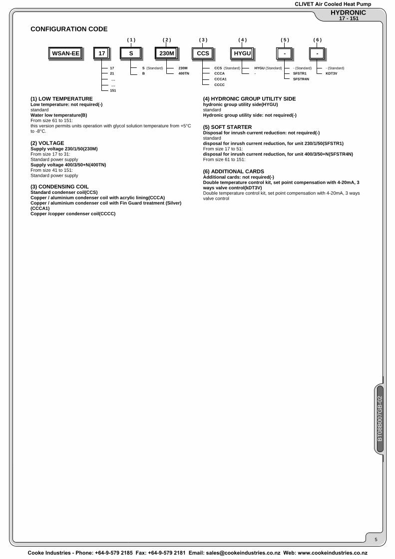
CONFIGURATION CODE
( 1 ) ( 2 ) ( 3 ) ( 4 ) ( 5 ) ( 6 )
WSAN-EE 17 S 230M CCS HYGU - -
17 S (Standard) 230M CCS (Standard) HYGU (Standard) - (Standard) - (Standard)21 B 400TN CCCA - SFSTR1 KDT3V … CCCA1 SFSTR4N
… CCCC151
(1) LOW TEMPERATURE Low temperature: not required(-) standard Water low temperature(B) From size 61 to 151: this version permits units operation with glycol solution temperature from +5°C to -8°C. (2) VOLTAGE Supply voltage 230/1/50(230M) From size 17 to 31: Standard power supply Supply voltage 400/3/50+N(400TN) From size 41 to 151: Standard power supply (3) CONDENSING COIL Standard condenser coil(CCS) Copper / aluminium condenser coil with acrylic lining(CCCA) Copper / aluminium condenser coil with Fin Guard treatment (Silver)(CCCA1) Copper /copper condenser coil(CCCC)
(4) HYDRONIC GROUP UTILITY SIDE hydronic group utility side(HYGU) standard Hydronic group utility side: not required(-) (5) SOFT STARTER Disposal for inrush current reduction: not required(-) standard disposal for inrush current reduction, for unit 230/1/50(SFSTR1) From size 17 to 51: disposal for inrush current reduction, for unit 400/3/50+N(SFSTR4N) From size 61 to 151: (6) ADDITIONAL CARDS Additional cards: not required(-) Double temperature control kit, set point compensation with 4-20mA, 3 ways valve control(kDT3V) Double temperature control kit, set point compensation with 4-20mA, 3 ways valve control
BT0
8B00
7GB
-02
5
CLIVET Air Cooled Heat Pump
Cooke Industries - Phone: +64-9-579 2185 Fax: +64-9-579 2181 Email: [email protected] Web: www.cookeindustries.co.nz
HYDRONIC 17 - 151
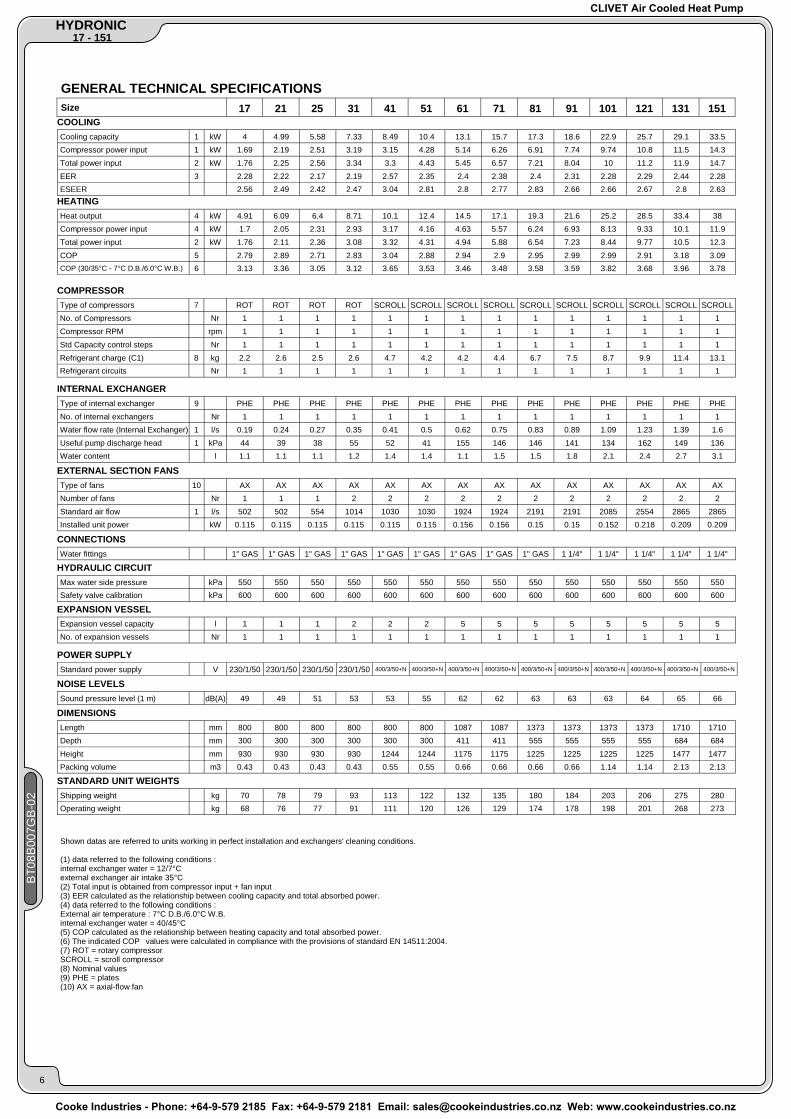
GENERAL TECHNICAL SPECIFICATIONS
Size 17 21 25 31 41 51 61 71 81 91 101 121 131 151 COOLING Cooling capacity 1 kW 4 4.99 5.58 7.33 8.49 10.4 13.1 15.7 17.3 18.6 22.9 25.7 29.1 33.5 Compressor power input 1 kW 1.69 2.19 2.51 3.19 3.15 4.28 5.14 6.26 6.91 7.74 9.74 10.8 11.5 14.3 Total power input 2 kW 1.76 2.25 2.56 3.34 3.3 4.43 5.45 6.57 7.21 8.04 10 11.2 11.9 14.7 EER 3 2.28 2.22 2.17 2.19 2.57 2.35 2.4 2.38 2.4 2.31 2.28 2.29 2.44 2.28 ESEER 2.56 2.49 2.42 2.47 3.04 2.81 2.8 2.77 2.83 2.66 2.66 2.67 2.8 2.63
HEATING Heat output 4 kW 4.91 6.09 6.4 8.71 10.1 12.4 14.5 17.1 19.3 21.6 25.2 28.5 33.4 38 Compressor power input 4 kW 1.7 2.05 2.31 2.93 3.17 4.16 4.63 5.57 6.24 6.93 8.13 9.33 10.1 11.9 Total power input 2 kW 1.76 2.11 2.36 3.08 3.32 4.31 4.94 5.88 6.54 7.23 8.44 9.77 10.5 12.3 COP 5 2.79 2.89 2.71 2.83 3.04 2.88 2.94 2.9 2.95 2.99 2.99 2.91 3.18 3.09 COP (30/35°C - 7°C D.B./6.0°C W.B.) 6 3.13 3.36 3.05 3.12 3.65 3.53 3.46 3.48 3.58 3.59 3.82 3.68 3.96 3.78
COMPRESSOR Type of compressors 7 ROT ROT ROT ROT SCROLL SCROLL SCROLL SCROLL SCROLL SCROLL SCROLL SCROLL SCROLL SCROLL No. of Compressors Nr 1 1 1 1 1 1 1 1 1 1 1 1 1 1 Compressor RPM rpm 1 1 1 1 1 1 1 1 1 1 1 1 1 1 Std Capacity control steps Nr 1 1 1 1 1 1 1 1 1 1 1 1 1 1 Refrigerant charge (C1) 8 kg 2.2 2.6 2.5 2.6 4.7 4.2 4.2 4.4 6.7 7.5 8.7 9.9 11.4 13.1 Refrigerant circuits Nr 1 1 1 1 1 1 1 1 1 1 1 1 1 1
INTERNAL EXCHANGER Type of internal exchanger 9 PHE PHE PHE PHE PHE PHE PHE PHE PHE PHE PHE PHE PHE PHE No. of internal exchangers Nr 1 1 1 1 1 1 1 1 1 1 1 1 1 1 Water flow rate (Internal Exchanger) 1 l/s 0.19 0.24 0.27 0.35 0.41 0.5 0.62 0.75 0.83 0.89 1.09 1.23 1.39 1.6 Useful pump discharge head 1 kPa 44 39 38 55 52 41 155 146 146 141 134 162 149 136 Water content l 1.1 1.1 1.1 1.2 1.4 1.4 1.1 1.5 1.5 1.8 2.1 2.4 2.7 3.1
EXTERNAL SECTION FANS Type of fans 10 AX AX AX AX AX AX AX AX AX AX AX AX AX AX Number of fans Nr 1 1 1 2 2 2 2 2 2 2 2 2 2 2 Standard air flow 1 l/s 502 502 554 1014 1030 1030 1924 1924 2191 2191 2085 2554 2865 2865 Installed unit power kW 0.115 0.115 0.115 0.115 0.115 0.115 0.156 0.156 0.15 0.15 0.152 0.218 0.209 0.209
CONNECTIONS Water fittings 1" GAS 1" GAS 1" GAS 1" GAS 1" GAS 1" GAS 1" GAS 1" GAS 1" GAS 1 1/4" 1 1/4" 1 1/4" 1 1/4" 1 1/4"
HYDRAULIC CIRCUIT Max water side pressure kPa 550 550 550 550 550 550 550 550 550 550 550 550 550 550 Safety valve calibration kPa 600 600 600 600 600 600 600 600 600 600 600 600 600 600
EXPANSION VESSEL Expansion vessel capacity l 1 1 1 2 2 2 5 5 5 5 5 5 5 5 No. of expansion vessels Nr 1 1 1 1 1 1 1 1 1 1 1 1 1 1
POWER SUPPLY Standard power supply V 230/1/50 230/1/50 230/1/50 230/1/50 400/3/50+N 400/3/50+N 400/3/50+N 400/3/50+N 400/3/50+N 400/3/50+N 400/3/50+N 400/3/50+N 400/3/50+N 400/3/50+N
NOISE LEVELS Sound pressure level (1 m) dB(A) 49 49 51 53 53 55 62 62 63 63 63 64 65 66
DIMENSIONS Length mm 800 800 800 800 800 800 1087 1087 1373 1373 1373 1373 1710 1710 Depth mm 300 300 300 300 300 300 411 411 555 555 555 555 684 684 Height mm 930 930 930 930 1244 1244 1175 1175 1225 1225 1225 1225 1477 1477 Packing volume m3 0.43 0.43 0.43 0.43 0.55 0.55 0.66 0.66 0.66 0.66 1.14 1.14 2.13 2.13
STANDARD UNIT WEIGHTS Shipping weight kg 70 78 79 93 113 122 132 135 180 184 203 206 275 280 Operating weight kg 68 76 77 91 111 120 126 129 174 178 198 201 268 273
Shown datas are referred to units working in perfect installation and exchangers' cleaning conditions. (1) data referred to the following conditions : internal exchanger water = 12/7°C external exchanger air intake 35°C (2) Total input is obtained from compressor input + fan input (3) EER calculated as the relationship between cooling capacity and total absorbed power. (4) data referred to the following conditions : External air temperature : 7°C D.B./6.0°C W.B. internal exchanger water = 40/45°C (5) COP calculated as the relationship between heating capacity and total absorbed power. (6) The indicated COP�values were calculated in compliance with the provisions of standard EN 14511:2004. (7) ROT = rotary compressor SCROLL = scroll compressor (8) Nominal values (9) PHE = plates (10) AX = axial-flow fan
BT0
8B00
7GB
-02
6
CLIVET Air Cooled Heat Pump
Cooke Industries - Phone: +64-9-579 2185 Fax: +64-9-579 2181 Email: [email protected] Web: www.cookeindustries.co.nz

17 - 151 HYDRONIC
BT0
8B00
7GB
-02
7
Voltage: 230/1/50
ELECTRICAL DATA Size 17 21 25 31 41 51
F.L.A. - FULL LOAD CURRENT AT MAX ADMISSIBLE CONDITIONS F.L.A. - Pump A 0.95 0.95 0.95 1.18 1.18 1.18 F.L.A. - Total A 11.82 14.77 15.44 20.66 24.46 32.06
L.R.A. LOCKED ROTOR AMPERES L.R.A. - Compressor 1 A 43 62 62 88 97 130
F.L.I. FULL LOAD POWER INPUT AT MAX ADMISSIBLE CONDITION F.L.I. - Pump kW 0.2 0.2 0.2 0.27 0.27 0.27 F.L.I. - Total kW 2.58 3.19 3.34 4.74 5.02 6.03
M.I.C. MAXIMUM INRUSH CURRENT M.I.C. - Value A 44.49 63.49 63.49 90.26 99.26 132.26
power supply 230/1/50 Hz +/-6% The pump is included in the total values calculation for non standard voltage please contact Clivet technical office The units are compliant with the provisions of European standards CEI EN 60204 and CEI EN 60335.
Voltage: 400/3/50+N
ELECTRICAL DATA Size 31 41 51 61 71 81 91 101 121 131 151
F.L.A. - FULL LOAD CURRENT AT MAX ADMISSIBLE CONDITIONS F.L.A. - Pump A 1.18 1.18 1.18 3.2 3.2 3.2 3.2 1.45 1.58 1.58 1.58 F.L.A. - Total A 9.11 9.86 12.56 15.68 18.78 19.98 20.98 23.43 26.06 28.87 33.87
L.R.A. LOCKED ROTOR AMPERES L.R.A. - Compressor 1 A 33 48 64 74 101 95 111 118 118 140 173
F.L.I. FULL LOAD POWER INPUT AT MAX ADMISSIBLE CONDITION F.L.I. - Pump kW 0.27 0.27 0.27 0.66 0.66 0.66 0.66 0.61 0.82 0.82 0.82 F.L.I. - Total kW 4.74 4.86 6.33 7.6 9.2 10.05 11.15 12.9 14.6 15.85 18.2
M.I.C. MAXIMUM INRUSH CURRENT M.I.C. - Value A 35.26 49.08 65.08 78.48 105.48 99.48 115.48 120.73 121.26 143.26 176.26
power supply 400/3/50 (+ NEUTRAL) +/- 6% Maximum Phase Unbalance: 2% The pump is included in the total values calculation for non standard voltage please contact Clivet technical office The units are compliant with the provisions of European standards CEI EN 60204 and CEI EN 60335.
OPERATING LIMITS (COOLING) Size 17 21 25 31 41 51 61 71 81 91 101 121 131 151
EXTERNAL EXCHANGER Max air intake temperature 1 °C 51 50 49 50 52 49 47 45 46 46 45 46 47 45
INTERNAL EXCHANGER Max water inlet temperature 2 °C 21 21 22 22 22 22 23 23 23 23 23 23 23 23 Min. water outlet temperature 3 °C 3 3 3 3 3 3 3 3 3 3 3 3 3 3
difference between inlet / outlet water temperature = 5°C Delta temperature min/max=3/8°C ATTENTION: IN CASE OF PREDOMINANT WINDS, WINDBREAK BARRIERS ARE NECESSARY. Data refer to unit operating with fans at max. flow-rate. It follows an energy efficiency increa-se, but also a sound pressure increase of about 2/3 dB(A). (1) internal exchanger water = 12/7°C (2) external exchanger air intake 30°C Maximum exchanger inlet water temperature 32°C during max. 15 minutes, thanks to the variable flow rate device for the circulator (standard). (size 61-71-81-91-101-121)
(3) Antifreeze (std) (4) Data referred to still air internal exchanger water = 40/45°C Internal exchanger water outlet temperature=38°C (5) Internal exchanger water outlet temperature=38°C (6) room temperature = 7°C (RH = 85%) (7) Minimum water temperature at exchanger inlet 14°C during max. 15 minutes, thanks to the variable flow rate device of the circulator (standard). (size 61-71-81-91-101-121)
OPERATING LIMITS (HEATING) EXTERNAL EXCHANGER
Max air temperature inlet (WB) 4 °C 25 25 25 25 25 25 25 25 25 25 25 25 25 25 Min air inlet temperature (W.B.) 5 °C -15 -15 -15 -15 -15 -15 -14 -14 -15 -15 -13 -15 -15 -15
INTERNAL EXCHANGER
Max water inlet temperature 6 °C 48 49 51 51 51 51 50 51 51 51 50 51 52 52 Min. water inlet temperature 7 °C 20 20 20 20 20 20 20 20 20 20 20 20 20 20
CLIVET Air Cooled Heat Pump
Cooke Industries - Phone: +64-9-579 2185 Fax: +64-9-579 2181 Email: [email protected] Web: www.cookeindustries.co.nz

HYDRONIC 17 - 151
FOULING CORRECTION FACTOR
m² °C/W F1 FK1
0.44 x 10^(-4) 1.00 1.00 0.88 x 10^(-4) 0.97 0.99 1.76 x 10^(-4) 0.94 0.98
INTERNAL EXCHANGER
The cooling performance values provided in the tables are based on the external exchanger having clean plates (fouling factor 1). For different fouling factor values, multiply the performance by the coefficients shown in the table. F1 = Cooling capacity correction factors FK1 = Compressor power input correction factor
SOUND LEVELS
Size Sound Power Level (dB) Sound
pressure level Octave band (Hz)
63 63 125 125 250 250 500 500 dB(A) dB(A)
17 67 67 68 68 62 62 61 61 49 61 21 69 69 68 68 62 62 61 61 49 62 25 72 72 70 70 65 65 63 63 51 64 31 73 73 70 70 67 67 64 64 53 67 41 74 74 71 71 68 68 65 65 53 68 51 75 75 70 70 68 68 67 67 55 69 61 86 81 80 72 72 65 56 49 62 77 71 86 81 80 73 72 65 57 49 62 77 81 86 81 81 76 72 66 57 50 63 78 91 86 81 81 75 71 66 58 51 63 78 101 86 84 77 75 73 69 62 56 63 78 121 87 83 82 77 74 68 62 55 64 80 131 87 81 86 77 74 69 59 52 65 81 151 84 81 88 79 72 69 55 48 66 82
Sound power level
Measures according to ISO 3744 regulations, with respect to the EUROVENT 8/1 certification. The sound pressure is measured at 1 m from the external surface of the unit in open field conditions. data referred to the following conditions : Internal exchanger water = 12/7 °C; outdoor air temperature 35°C
CORRECTION FACTOR FOR ANTIFREEZE SOLUTIONS
5% 10% 15% 20% 25% 30% 35% 40% Freezing temperature °C -2.0 -3.9 -6.5 -8.9 -11.8 -15.6 -19.0 -23.4 Safety temperature °C 3.0 1.0 -1.0 -4.0 -6.0 -10.0 -14.0 -19.0 Cooling Capacity Factor Nr 0.995 0.990 0.985 0.981 0.977 0.974 0.971 0.968 Compressor input Factor Nr 0.997 0.993 0.990 0.988 0.986 0.984 0.982 0.981 Internal exchanger Glycol solution flow Factor Nr 1.003 1.010 1.020 1.033 1.050 1.072 1.095 1.124 Pressure drop Factor Nr 1.029 1.060 1.090 1.118 1.149 1.182 1.211 1.243
% ethylene glycol by weight
The correction factors shown refer to water and glycol ethylene mixes used to prevent the formation of frost on the exchangers in the water circuit during inactivity in winter.
INTEGRATED HEATING CAPACITIES
Air temperature external exchanger inlet °C (D.B. / W.B.) -5 / -5.4 0 / -0.6 5 / 3.9 OTHERS Heating capacity multiplication coefficient 0.89 0.88 0.94 1 To obtain the integrated heating capacities (the real heating capacity considering the defrost cycles too), multiply the kWt value in the heating performance tables by the following coefficient.
BT0
8B00
7GB
-02
8
CLIVET Air Cooled Heat Pump
Cooke Industries - Phone: +64-9-579 2185 Fax: +64-9-579 2181 Email: [email protected] Web: www.cookeindustries.co.nz

17 - 151 HYDRONIC
PUMP PERFORMANCE
PUMP PERFORMANCE(1)
10
20
30
40
50
60
70
80
90
100
110
0,1 0,2 0,3 0,4 0,5 0,6Q (l/s)
DP
(kPa
)
4131 5121 2517
PUMP PERFORMANCE(2)
102030405060708090
100110120130140150160170180190200
0,5 0,6 0,7 0,8 0,9 1,0 1,1 1,2 1,3 1,4 1,5 1,6 1,7 1,8 1,9 2,0 2,1 2,2 2,3 2,4 2,5
Q (l/s)
DP (k
Pa)
61
151
131121
101
91
71-81
EXCHANGER PRESSURE DROP LIMIT. WARNING: DON'T USE OVER THIS LIMIT EXCHANGER PRESSURE DROPS
10
20
30
40
50
60
70
80
0,1 0,2 0,3 0,4 0,5 0,6 0,7
Q (l/s)
DP
(kPa
)
17 21 51413125
UNIT WITHOUT HYDRONIC ASSEMBLY DP = PRESSURE DROP Q = WATER FLOW
EXCHAMGER PRESSURE DROP LIMIT. WARNING: DON'T USE BELOW THIS LIMIT.
EXCHANGER PRESSURE DROPS EXCHANGER PRESSURE DROP LIMIT. WARNING: DON'T USE OVER THIS LIMIT
10
20
30
40
50
60
70
80
0,3 0,4 0,5 0,6 0,7 0,8 0,9 1,0 1,1 1,2 1,3 1,4 1,5 1,6 1,7 1,8 1,9 2,0
Q (l/s)
DP
(kPa
)
61 71-81 91
151
131
121101
EXCHANGER PRESSURE DROP LIMIT. WARNING: DON'T USE OVER THIS LIMIT
BT0
8B00
7GB
-02
9
CURVE OF DISCHARGE HEAD WITH HYDRONIC ASSEMBLY DP[KPA]=USEFUL DISCHARGE HEAD Q[L/S]= WATER-FLOW RATE THE HEADS ARE INTENDED AS AVAILABLE AT THE UNIT CONNECTIONS
CLIVET Air Cooled Heat Pump
Cooke Industries - Phone: +64-9-579 2185 Fax: +64-9-579 2181 Email: [email protected] Web: www.cookeindustries.co.nz

HYDRONIC 17 - 151
BT0
8B00
7GB
-02
10
COOLING PERFORMANCE
Size
17
21
25
31
41
51
61
To (ºC)
6
7
8
9
10
11
6
7
8
9
10
11
6
7
8
9
10
11
6
7
8
9
10
11
6
7
8
9
10
11
6
7
8
9
10
11
6
7
8
9
10
11
EXTERNAL EXCHANGER AIR TEMPERATURE (°C)
25 30 35 40 43
kWf kWe kWf kWe kWf kWe kWf kWe kWf kWe kWf kWe
45
4.35 1.43 4.13 1.55 3.89 1.68 3.63 1.81 3.48 1.89 3.37 1.94
4.47 1.43 4.24 1.56 4.00 1.69 3.74 1.82 3.58 1.90 3.47 1.96
4.60 1.44 4.36 1.57 4.11 1.70 3.85 1.84 3.69 1.92 3.58 1.98
4.72 1.45 4.48 1.58 4.23 1.71 3.97 1.85 3.81 1.94 3.70 2.00
4.86 1.45 4.61 1.59 4.36 1.73 4.09 1.87 3.93 1.95 3.82 2.01
5.00 1.46 4.75 1.60 4.49 1.74 4.22 1.88 4.06 1.97 3.94 2.03
5.45 1.84 5.15 2.00 4.85 2.17 4.54 2.36 4.35 2.47 4.22 2.55
5.61 1.86 5.30 2.02 4.99 2.19 4.67 2.38 4.48 2.50 4.35 2.58
5.77 1.87 5.46 2.04 5.14 2.22 4.81 2.40 4.62 2.52 4.48 2.60
5.94 1.89 5.62 2.06 5.29 2.24 4.96 2.43 4.76 2.55 4.62 2.63
6.11 1.90 5.78 2.08 5.45 2.26 5.11 2.45 4.91 2.57 4.77 2.66
6.29 1.92 5.95 2.09 5.61 2.28 5.27 2.48 5.06 2.60 4.93 2.68
6.09 2.13 5.77 2.30 5.43 2.49 5.10 2.68 4.90 2.80 4.76 2.89
6.25 2.15 5.92 2.33 5.58 2.51 5.24 2.71 5.03 2.83 4.89 2.92
6.42 2.17 6.08 2.35 5.73 2.53 5.38 2.73 5.17 2.86 5.03 2.95
6.59 2.19 6.24 2.37 5.89 2.56 5.53 2.76 5.31 2.89 5.16 2.98
6.77 2.21 6.42 2.39 6.05 2.58 5.68 2.79 5.46 2.93
6.95 2.22 6.60 2.41 6.23 2.61 5.84 2.82 5.61 2.96
8.06 2.68 7.60 2.92 7.12 3.16 6.63 3.40 6.33 3.55 6.13 3.64
8.29 2.70 7.82 2.95 7.33 3.19 6.83 3.43 6.52 3.58 6.31 3.68
8.54 2.73 8.05 2.97 7.55 3.22 7.03 3.46 6.71 3.61 6.49 3.71
8.79 2.75 8.29 3.00 7.78 3.24 7.24 3.50 6.91 3.65 6.68 3.75
9.05 2.77 8.54 3.02 8.01 3.27 7.46 3.53 7.11 3.68 6.88 3.79
9.31 2.80 8.79 3.05 8.25 3.30 7.68 3.56 7.32 3.72 7.08 3.82
9.27 2.50 8.76 2.81 8.24 3.14 7.71 3.49 7.39 3.70 7.17 3.85
9.55 2.52 9.02 2.82 8.49 3.15 7.94 3.50 7.61 3.72 7.39 3.87
9.82 2.53 9.29 2.84 8.74 3.17 8.18 3.51 7.84 3.73 7.62 3.88
10.1 2.55 9.56 2.86 9.00 3.18 8.43 3.53 8.09 3.74 7.86 3.89
10.4 2.56 9.84 2.87 9.27 3.20 8.69 3.55 8.34 3.76 8.11 3.91
10.7 2.58 10.1 2.89 9.55 3.22 8.96 3.56 8.60 3.78 8.36 3.92
11.4 3.35 10.8 3.79 10.2 4.26 9.54 4.77 9.17 5.09 8.93 5.30
11.7 3.38 11.1 3.82 10.4 4.28 9.82 4.78 9.44 5.09 9.18 5.30
12.0 3.41 11.4 3.84 10.7 4.30 10.1 4.79 9.71 5.09 9.45 5.30
12.3 3.45 11.7 3.87 11.1 4.32 10.4 4.80 10.00 5.10 9.73 5.30
12.7 3.48 12.0 3.90 11.4 4.34 10.7 4.81 10.3 5.10 10.0 5.30
13.0 3.50 12.3 3.93 11.7 4.36 11.0 4.82 10.6 5.11 10.3 5.30
14.3 4.11 13.6 4.58 12.7 5.09 11.8 5.65 11.3 6.01 10.9 6.26
14.7 4.15 13.9 4.62 13.1 5.14 12.2 5.70 11.6 6.05 11.2 6.29
15.1 4.19 14.3 4.67 13.4 5.18 12.5 5.74 12.0 6.09 11.6 6.33
15.5 4.23 14.6 4.71 13.8 5.23 12.9 5.78 12.3 6.13 12.0 6.37
15.9 4.27 15.0 4.75 14.1 5.27 13.2 5.82 12.7 6.16 12.3 6.40
16.3 4.30 15.4 4.79 14.5 5.30 13.6 5.85 13.0 6.20 12.7 6.43
kWf = Cooling capacity in kW kWe = Compressor power input in kW To = Internal exchanger water outlet temperature in° C Performances in function of the inlet/outlet water temperature differential = 5°C The performance refers to rated air flow. Data listed in the tables are based on plate exchangers without fouling and clean coils. For different situation it is necessary to use adeguate correction factors.
CLIVET Air Cooled Heat Pump
Cooke Industries - Phone: +64-9-579 2185 Fax: +64-9-579 2181 Email: [email protected] Web: www.cookeindustries.co.nz

17 - 151 HYDRONIC
BT0
8B00
7GB
-02
11
COOLING PERFORMANCE
Size
71
81
91
101
121
131
151
To (ºC)
6
7
8
9
10
11
6
7
8
9
10
11
6
7
8
9
10
11
6
7
8
9
10
11
6
7
8
9
10
11
6
7
8
9
10
11
6
7
8
9
10
11
EXTERNAL EXCHANGER AIR TEMPERATURE (°C)
25 30 35 40 43
kWf kWe kWf kWe kWf kWe kWf kWe kWf kWe kWf kWe
45
17.1 5.07 16.2 5.63 15.2 6.22 14.2 6.83 13.6 7.21 13.1 7.46
17.6 5.12 16.7 5.68 15.7 6.26 14.6 6.87 14.0 7.25 13.5 7.51
18.1 5.16 17.1 5.72 16.1 6.31 15.0 6.92 14.4 7.30 18.6 5.22 17.6 5.77 16.5 6.35 15.4 6.97 14.8 7.36 19.1 5.27 18.1 5.82 17.0 6.41 15.8 7.03 15.1 7.42 19.6 5.32 18.5 5.87 17.4 6.46 16.2 7.09 15.5 7.48
19.0 5.51 18.0 6.15 16.8 6.87 15.6 7.66 14.8 8.18 14.2 8.53
19.6 5.55 18.5 6.19 17.3 6.91 16.0 7.71 15.2 8.22 14.6 8.58
20.1 5.60 19.1 6.23 17.8 6.95 16.5 7.75 15.6 8.27 15.0 8.63
20.7 5.64 19.6 6.28 18.4 6.99 17.0 7.79 16.1 8.30 15.4 8.67
21.2 5.69 20.1 6.32 18.9 7.03 17.4 7.82 16.5 8.34 15.8 8.70
21.8 5.74 20.7 6.37 19.4 7.07 17.9 7.86 17.0 8.36 16.3 8.72
20.2 6.33 19.2 6.99 18.1 7.69 17.0 8.41 16.4 8.86 15.9 9.16
20.8 6.38 19.7 7.04 18.6 7.74 17.5 8.46 16.9 8.90 16.4 9.20
21.3 6.43 20.2 7.09 19.1 7.79 18.0 8.51 17.4 8.95 17.0 9.26
21.9 6.48 20.7 7.15 19.6 7.85 18.6 8.57 17.9 9.02 17.5 9.32
22.4 6.54 21.3 7.21 20.2 7.91 19.1 8.63 18.5 9.08 18.1 9.39
23.0 6.60 21.8 7.27 20.7 7.97 19.7 8.71 19.0 9.16 18.6 9.47
25.4 7.83 24.0 8.67 22.4 9.63 20.4 10.7 19.1 11.4 18.2 11.9
26.0 7.94 24.5 8.79 22.9 9.74 21.0 10.8 19.7 11.4 18.8 11.9
26.6 8.04 25.1 8.90 23.4 9.84 21.5 10.9 20.3 11.5 27.2 8.14 25.6 9.01 23.9 9.94 22.1 10.9 20.9 11.6 27.8 8.24 26.2 9.12 24.5 10.0 22.7 11.0 21.5 11.6 28.5 8.33 26.9 9.21 25.1 10.1 23.3 11.1 22.2 11.7
28.1 8.81 26.5 9.77 24.9 10.8 23.3 11.7 22.2 12.3 21.6 12.7
29.0 8.84 27.4 9.78 25.7 10.8 23.9 11.8 22.8 12.4 22.0 12.9
29.8 8.87 28.2 9.80 26.5 10.8 24.5 11.8 23.3 12.5 22.4 13.0
30.7 8.91 29.1 9.83 27.2 10.8 25.2 11.9 23.8 12.6 22.9 13.1
31.5 8.96 29.9 9.87 27.9 10.9 25.8 12.0 24.4 12.7 23.4 13.1
32.4 9.02 30.6 9.91 28.7 10.9 26.4 12.0 24.9 12.7 23.9 13.2
31.3 9.42 29.9 10.3 28.3 11.4 26.5 12.5 25.4 13.3 24.5 13.8
32.3 9.47 30.8 10.4 29.1 11.5 27.2 12.6 26.1 13.3 25.3 13.8
33.3 9.52 31.6 10.5 29.8 11.6 28.0 12.7 26.8 13.4 26.1 13.9
34.3 9.59 32.5 10.6 30.6 11.7 28.7 12.8 27.6 13.5 26.8 13.9
35.2 9.66 33.3 10.7 31.4 11.8 29.5 12.9 28.3 13.5 27.5 14.0
36.1 9.75 34.2 10.8 32.2 11.8 30.2 12.9 29.1 13.6 28.3 14.1
35.9 11.5 34.2 12.8 32.6 14.1 31.0 15.6 30.1 16.6 29.4 17.3
36.9 11.6 35.2 12.9 33.5 14.3 31.9 15.8 31.0 16.8 30.3 17.5
38.0 11.7 36.2 13.0 34.4 14.4 32.8 15.9 31.8 16.9 39.0 11.8 37.1 13.1 35.3 14.5 33.6 16.1 32.7 17.1 40.0 11.9 38.1 13.2 36.2 14.7 34.5 16.2 33.5 17.2 41.1 12.0 39.1 13.3 37.2 14.8 35.3 16.3 34.3 17.3
kWf = Cooling capacity in kW kWe = Compressor power input in kW To = Internal exchanger water outlet temperature in° C Performances in function of the inlet/outlet water temperature differential = 5°C The performance refers to rated air flow. Data listed in the tables are based on plate exchangers without fouling and clean coils. For different situation it is necessary to use adeguate correction factors.
CLIVET Air Cooled Heat Pump
Cooke Industries - Phone: +64-9-579 2185 Fax: +64-9-579 2181 Email: [email protected] Web: www.cookeindustries.co.nz
HYDRONIC 17 - 151
BT0
8B00
7GB
-02
12
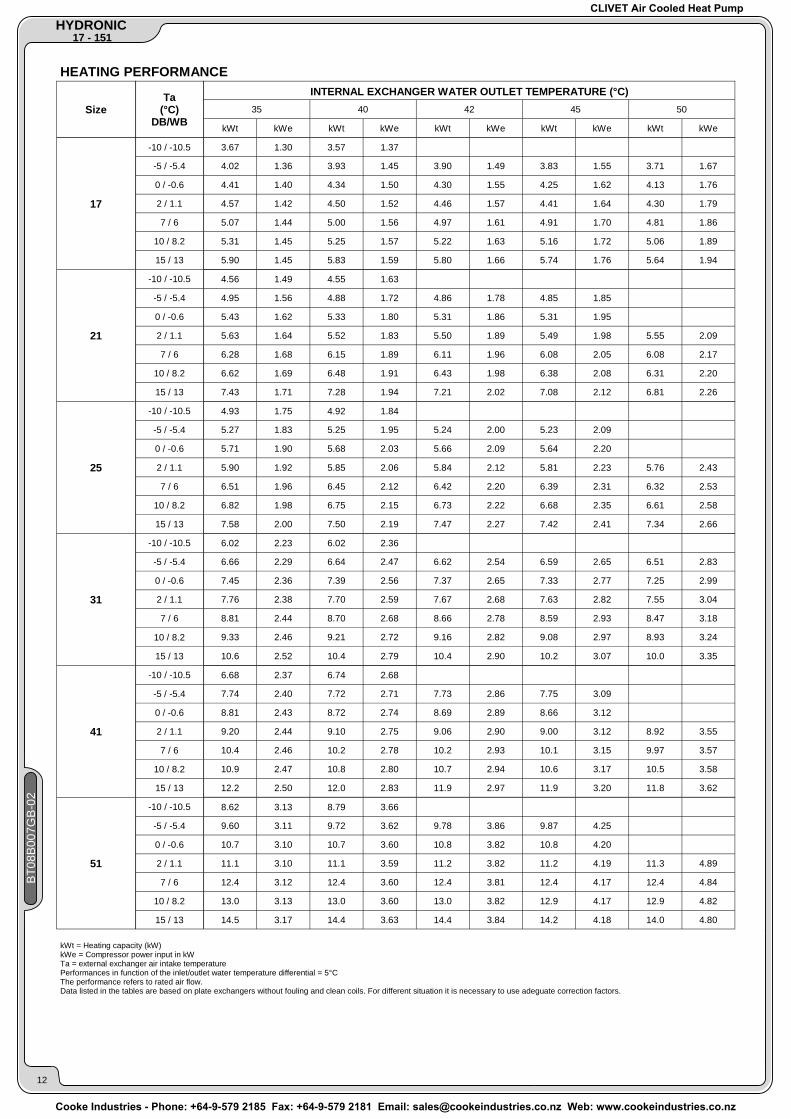
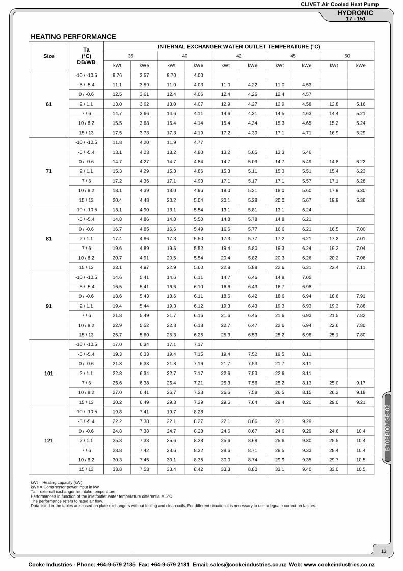
HEATING PERFORMANCE
Size
17
21
25
31
41
51
Ta (°C)
DB/WB
-10 / -10.5
-5 / -5.4
0 / -0.6
2 / 1.1
7 / 6
10 / 8.2
15 / 13
-10 / -10.5
-5 / -5.4
0 / -0.6
2 / 1.1
7 / 6
10 / 8.2
15 / 13
-10 / -10.5
-5 / -5.4
0 / -0.6
2 / 1.1
7 / 6
10 / 8.2
15 / 13
-10 / -10.5
-5 / -5.4
0 / -0.6
2 / 1.1
7 / 6
10 / 8.2
15 / 13
-10 / -10.5
-5 / -5.4
0 / -0.6
2 / 1.1
7 / 6
10 / 8.2
15 / 13
-10 / -10.5
-5 / -5.4
0 / -0.6
2 / 1.1
7 / 6
10 / 8.2
15 / 13
INTERNAL EXCHANGER WATER OUTLET TEMPERATURE (°C) 35 40 42 45
kWt kWe kWt kWe kWt kWe kWt kWe kWt kWe
50
3.67 1.30 3.57 1.37 4.02 1.36 3.93 1.45 3.90 1.49 3.83 1.55 3.71 1.67
4.41 1.40 4.34 1.50 4.30 1.55 4.25 1.62 4.13 1.76
4.57 1.42 4.50 1.52 4.46 1.57 4.41 1.64 4.30 1.79
5.07 1.44 5.00 1.56 4.97 1.61 4.91 1.70 4.81 1.86
5.31 1.45 5.25 1.57 5.22 1.63 5.16 1.72 5.06 1.89
5.90 1.45 5.83 1.59 5.80 1.66 5.74 1.76 5.64 1.94
4.56 1.49 4.55 1.63 4.95 1.56 4.88 1.72 4.86 1.78 4.85 1.85 5.43 1.62 5.33 1.80 5.31 1.86 5.31 1.95 5.63 1.64 5.52 1.83 5.50 1.89 5.49 1.98 5.55 2.09
6.28 1.68 6.15 1.89 6.11 1.96 6.08 2.05 6.08 2.17
6.62 1.69 6.48 1.91 6.43 1.98 6.38 2.08 6.31 2.20
7.43 1.71 7.28 1.94 7.21 2.02 7.08 2.12 6.81 2.26
4.93 1.75 4.92 1.84 5.27 1.83 5.25 1.95 5.24 2.00 5.23 2.09 5.71 1.90 5.68 2.03 5.66 2.09 5.64 2.20
5.90 1.92 5.85 2.06 5.84 2.12 5.81 2.23 5.76 2.43
6.51 1.96 6.45 2.12 6.42 2.20 6.39 2.31 6.32 2.53
6.82 1.98 6.75 2.15 6.73 2.22 6.68 2.35 6.61 2.58
7.58 2.00 7.50 2.19 7.47 2.27 7.42 2.41 7.34 2.66
6.02 2.23 6.02 2.36 6.66 2.29 6.64 2.47 6.62 2.54 6.59 2.65 6.51 2.83
7.45 2.36 7.39 2.56 7.37 2.65 7.33 2.77 7.25 2.99
7.76 2.38 7.70 2.59 7.67 2.68 7.63 2.82 7.55 3.04
8.81 2.44 8.70 2.68 8.66 2.78 8.59 2.93 8.47 3.18
9.33 2.46 9.21 2.72 9.16 2.82 9.08 2.97 8.93 3.24
10.6 2.52 10.4 2.79 10.4 2.90 10.2 3.07 10.0 3.35
6.68 2.37 6.74 2.68 7.74 2.40 7.72 2.71 7.73 2.86 7.75 3.09 8.81 2.43 8.72 2.74 8.69 2.89 8.66 3.12 9.20 2.44 9.10 2.75 9.06 2.90 9.00 3.12 8.92 3.55
10.4 2.46 10.2 2.78 10.2 2.93 10.1 3.15 9.97 3.57
10.9 2.47 10.8 2.80 10.7 2.94 10.6 3.17 10.5 3.58
12.2 2.50 12.0 2.83 11.9 2.97 11.9 3.20 11.8 3.62
8.62 3.13 8.79 3.66 9.60 3.11 9.72 3.62 9.78 3.86 9.87 4.25 10.7 3.10 10.7 3.60 10.8 3.82 10.8 4.20 11.1 3.10 11.1 3.59 11.2 3.82 11.2 4.19 11.3 4.89
12.4 3.12 12.4 3.60 12.4 3.81 12.4 4.17 12.4 4.84
13.0 3.13 13.0 3.60 13.0 3.82 12.9 4.17 12.9 4.82
14.5 3.17 14.4 3.63 14.4 3.84 14.2 4.18 14.0 4.80
kWt = Heating capacity (kW) kWe = Compressor power input in kW Ta = external exchanger air intake temperature Performances in function of the inlet/outlet water temperature differential = 5°C The performance refers to rated air flow. Data listed in the tables are based on plate exchangers without fouling and clean coils. For different situation it is necessary to use adeguate correction factors.
CLIVET Air Cooled Heat Pump
Cooke Industries - Phone: +64-9-579 2185 Fax: +64-9-579 2181 Email: [email protected] Web: www.cookeindustries.co.nz
17 - 151 HYDRONIC
BT0
8B00
7GB
-02
13
HEATING PERFORMANCE
Size
61
71
81
91
101
121
Ta (°C)
DB/WB
-10 / -10.5
-5 / -5.4
0 / -0.6
2 / 1.1
7 / 6
10 / 8.2
15 / 13
-10 / -10.5
-5 / -5.4
0 / -0.6
2 / 1.1
7 / 6
10 / 8.2
15 / 13
-10 / -10.5
-5 / -5.4
0 / -0.6
2 / 1.1
7 / 6
10 / 8.2
15 / 13
-10 / -10.5
-5 / -5.4
0 / -0.6
2 / 1.1
7 / 6
10 / 8.2
15 / 13
-10 / -10.5
-5 / -5.4
0 / -0.6
2 / 1.1
7 / 6
10 / 8.2
15 / 13
-10 / -10.5
-5 / -5.4
0 / -0.6
2 / 1.1
7 / 6
10 / 8.2
15 / 13
INTERNAL EXCHANGER WATER OUTLET TEMPERATURE (°C) 35 40 42 45
kWt kWe kWt kWe kWt kWe kWt kWe kWt kWe
50
9.76 3.57 9.70 4.00 11.1 3.59 11.0 4.03 11.0 4.22 11.0 4.53 12.5 3.61 12.4 4.06 12.4 4.26 12.4 4.57 13.0 3.62 13.0 4.07 12.9 4.27 12.9 4.58 12.8 5.16
14.7 3.66 14.6 4.11 14.6 4.31 14.5 4.63 14.4 5.21
15.5 3.68 15.4 4.14 15.4 4.34 15.3 4.65 15.2 5.24
17.5 3.73 17.3 4.19 17.2 4.39 17.1 4.71 16.9 5.29
11.8 4.20 11.9 4.77 13.1 4.23 13.2 4.80 13.2 5.05 13.3 5.46 14.7 4.27 14.7 4.84 14.7 5.09 14.7 5.49 14.8 6.22
15.3 4.29 15.3 4.86 15.3 5.11 15.3 5.51 15.4 6.23
17.2 4.36 17.1 4.93 17.1 5.17 17.1 5.57 17.1 6.28
18.1 4.39 18.0 4.96 18.0 5.21 18.0 5.60 17.9 6.30
20.4 4.48 20.2 5.04 20.1 5.28 20.0 5.67 19.9 6.36
13.1 4.90 13.1 5.54 13.1 5.81 13.1 6.24 14.8 4.86 14.8 5.50 14.8 5.78 14.8 6.21 16.7 4.85 16.6 5.49 16.6 5.77 16.6 6.21 16.5 7.00
17.4 4.86 17.3 5.50 17.3 5.77 17.2 6.21 17.2 7.01
19.6 4.89 19.5 5.52 19.4 5.80 19.3 6.24 19.2 7.04
20.7 4.91 20.5 5.54 20.4 5.82 20.3 6.26 20.2 7.06
23.1 4.97 22.9 5.60 22.8 5.88 22.6 6.31 22.4 7.11
14.6 5.41 14.6 6.11 14.7 6.46 14.8 7.05 16.5 5.41 16.6 6.10 16.6 6.43 16.7 6.98 18.6 5.43 18.6 6.11 18.6 6.42 18.6 6.94 18.6 7.91
19.4 5.44 19.3 6.12 19.3 6.43 19.3 6.93 19.3 7.88
21.8 5.49 21.7 6.16 21.6 6.45 21.6 6.93 21.5 7.82
22.9 5.52 22.8 6.18 22.7 6.47 22.6 6.94 22.6 7.80
25.7 5.60 25.3 6.25 25.3 6.53 25.2 6.98 25.1 7.80
17.0 6.34 17.1 7.17 19.3 6.33 19.4 7.15 19.4 7.52 19.5 8.11 21.8 6.33 21.8 7.16 21.7 7.53 21.7 8.11 22.8 6.34 22.7 7.17 22.6 7.53 22.6 8.11 25.6 6.38 25.4 7.21 25.3 7.56 25.2 8.13 25.0 9.17
27.0 6.41 26.7 7.23 26.6 7.58 26.5 8.15 26.2 9.18
30.2 6.49 29.8 7.29 29.6 7.64 29.4 8.20 29.0 9.21
19.8 7.41 19.7 8.28 22.2 7.38 22.1 8.27 22.1 8.66 22.1 9.29 24.8 7.38 24.7 8.28 24.6 8.67 24.6 9.29 24.6 10.4
25.8 7.38 25.6 8.28 25.6 8.68 25.6 9.30 25.5 10.4
28.8 7.42 28.6 8.32 28.6 8.71 28.5 9.33 28.4 10.4
30.3 7.45 30.1 8.35 30.0 8.74 29.9 9.35 29.7 10.5
33.8 7.53 33.4 8.42 33.3 8.80 33.1 9.40 33.0 10.5
kWt = Heating capacity (kW) kWe = Compressor power input in kW Ta = external exchanger air intake temperature Performances in function of the inlet/outlet water temperature differential = 5°C The performance refers to rated air flow. Data listed in the tables are based on plate exchangers without fouling and clean coils. For different situation it is necessary to use adeguate correction factors.
CLIVET Air Cooled Heat Pump
Cooke Industries - Phone: +64-9-579 2185 Fax: +64-9-579 2181 Email: [email protected] Web: www.cookeindustries.co.nz

HYDRONIC 17 - 151
BT0
8B00
7GB
-02
14
HEATING PERFORMANCE
Size
131
151
Ta (°C)
DB/WB
-10 / -10.5
-5 / -5.4
0 / -0.6
2 / 1.1
7 / 6
10 / 8.2
15 / 13
-10 / -10.5
-5 / -5.4
0 / -0.6
2 / 1.1
7 / 6
10 / 8.2
15 / 13
INTERNAL EXCHANGER WATER OUTLET TEMPERATURE (°C) 35 40 42 45
kWt kWe kWt kWe kWt kWe kWt kWe kWt kWe
50
22.3 7.75 22.3 8.66 22.3 9.05 22.3 9.67 25.5 7.85 25.4 8.77 25.4 9.18 25.4 9.81 25.4 11.0
28.8 7.97 28.7 8.90 28.6 9.31 28.6 9.96 28.5 11.1
30.0 8.02 29.9 8.95 29.8 9.36 29.8 10.0 29.7 11.2
33.8 8.17 33.6 9.11 33.5 9.52 33.4 10.2 33.2 11.4
35.6 8.24 35.4 9.18 35.3 9.59 35.1 10.3 34.9 11.4
39.7 8.42 39.4 9.36 39.3 9.77 39.1 10.4 38.7 11.6
26.6 9.43 26.3 10.4 26.1 10.7 25.6 11.3 29.2 9.38 29.2 10.4 29.2 10.8 29.1 11.5 29.0 12.6
32.2 9.39 32.4 10.5 32.5 10.9 32.7 11.6 33.1 13.0
33.5 9.40 33.7 10.5 33.8 11.0 34.0 11.7 34.5 13.1
37.4 9.48 37.6 10.6 37.7 11.1 38.0 11.9 38.7 13.3
39.4 9.53 39.5 10.7 39.6 11.1 39.8 11.9 40.5 13.4
44.2 9.68 44.0 10.8 44.0 11.3 44.1 12.1 44.6 13.6 kWt = Heating capacity (kW) kWe = Compressor power input in kW Ta = external exchanger air intake temperature Performances in function of the inlet/outlet water temperature differential = 5°C The performance refers to rated air flow. Data listed in the tables are based on plate exchangers without fouling and clean coils. For different situation it is necessary to use adeguate correction factors.
CLIVET Air Cooled Heat Pump
Cooke Industries - Phone: +64-9-579 2185 Fax: +64-9-579 2181 Email: [email protected] Web: www.cookeindustries.co.nz

17 - 151 HYDRONIC
BT0
8B00
7GB
-02
15
ACCESSORIES Each accessory is marked by a configuration code, e.g. CMMBX. If the last letter is X, it means that the accessory is provided sepa-rately. If the code does not contain the letter X, the accessory is installed at the factory.
(CCCA -)Copper / aluminium condenser coils with acrylic lining
The copper/aluminium evaporator coils with acrylic lining can be used in the room where the ambient air contains a concentration of salt and other not very aggres-sive agents.
Configuration Detail
(CCCA1 -)Copper / aluminium condenser coils with Fin Guard (Silver) treatment
The Fin Guard Silver, for finned exchanger, is a polyurethane vernish waterproof (for waterworks, see and discharge water). It is also resistant to oil products and other different solvents. It hasn't any effects on the air side pressure drops.
Configuration Detail
(CCCC -)Copper / copper condenser coils The copper/copper condensing coil allows a better resistence to the natural agent like salt and sulphureous vapours.
Configuration Detail
(-)Unit without hydronic assembly
The unit can be requested without circulating pump, expansion vessel, safety valve water side and filling assembly.
Configuration Detail
(CMMBX -)Serial communication module to supervisor (MODBUS)
The serial communication module to supervisor (MODBUS) is connected with the principal module through a comb connection (see lay-out on electrical panel). In this way the remote assistance and supervision are available through standard MODBUS protocol.It is possible to connect to a single supervisor system up to 127 units. The connection to PC must be obtained through a converter RS485/232; the serial port RS232 admits as maximum a 10 m length. The serial communication module to supervisor (MODBUS) is necessary when the unit is connected to ELFOCONTROL.
12 Vac
gnd+-
81 2 3 4 5 6 7
CN2
12109 11
16
+5V 13
1415
gnd
1917
1821
20
SERIALETTL / RS485
CN1 gn
d12
VAC
+-
12 V AC
CN
1C
N1
19
18
2021
201
819
21
RS-485
RS-232
gnd
-
+
Supervisore
TTL /RS485
+-
ALLE ALTREUNITA’
12 V AC
gnd
TTL /RS485
-
gnd
+
separately supplied accessories
(PMX -)phase monitor The phase monitor allows to check the right presence of electric supply phases for 400/3/50 units. separately supplied accessories
CLIVET Air Cooled Heat Pump
Cooke Industries - Phone: +64-9-579 2185 Fax: +64-9-579 2181 Email: [email protected] Web: www.cookeindustries.co.nz

HYDRONIC 17 - 151
BT0
8B00
7GB
-02
16
(SPC3X -)Set point compensation with according to outdoor enthalpy
It allows to modulate the unit set point according to the external enthalpy. By energy efficiency optimization, it optimizes also the defrosting times during winter operation. The humidity probe is electronically connected to the main control module present in the unit.
separately supplied accessories
(KDT3V, KDT3VX -)Double temperature control kit, set point compensation with 4-20mA, 3 ways valve.
This accessory may wither be installed at the factory or provided separately. (KDT3V - )Configuration Detail (KDT3VX - )separately supplied accessories
This kit can be used to manage some of the main accessories supplied with the unit. It is especially useful for controlling a 3-way hot water valve, for managing two different set points depending on the water use, i.e. radiating panels and fan coils, and for activating set point compensation via a 4-20mA signal. It consists of an expansion board connected to the electronics in the standard unit. It can be used for: 1) The management of the various elements (circulating pump, mixer valve and delivery sensor) in order to ensure the correct water temperature when supplying the radiating panels. This accessory controls the mixer valve on the basis of the climatic curve parameters set in the unit microprocessor, and operates on the basis of the EXTERNAL air. Humidity control and all addi-tional regulations/controls are excluded from the Clivet supply. 2) Dynamic set point variation on the basis of a WATER RESET signal (4-20 mA) from an external device.
(1) UNIT ELECTRIC PANEL (2) EXPANSION VESSEL (3) SAFETY VALVE (4) PUMP (5) 3 WAYS-VALVE (OPTIONAL) (6) UNDERFLOOR HEATING (7) TERMINAL UNITS
Configuration Detail
separately supplied accessories
(SFSTR4N, SFSTR1 -)Disposal for inrush current reduction
(SFSTR1 - )disposal for inrush current reduction, for unit 230/1/50 (SFSTR4N - )disposal for inrush current reduction, for unit 400/3/50+N (only for sizes from 61 to 151)
Starting up a motor directly can overload the electricity network, with start-up currents up to 8 times the nominal current. Thanks to the breakaway current reduc-tion device, start-up takes place gradually, with the start-up current being limited during this period of time. The start-up current can therefore be reduced to 3.5 - 4 times the nominal current, meaning that the power systems and protection devices can be sized with lower parameters.
Configuration Detail
(AMRX -)Rubber antivibration mounts The rubber antivibration mounts reduce the vibrations of compressor during its operation and they are installed at the base toe.
separately supplied accessories
Diagram with the three-way valve located on the water supply, from the unit towards the system
CLIVET Air Cooled Heat Pump
Cooke Industries - Phone: +64-9-579 2185 Fax: +64-9-579 2181 Email: [email protected] Web: www.cookeindustries.co.nz

17 - 151 HYDRONIC
DIMENSIONAL DRAWING
800
157 510 133
336
W1
W4
W2
"G" W3
M N
PO
(13)500
(13)
150
(13)100
1
2
3
7
811
12
12
65
117
50
96
63
118
300
336
360
1
3
4
5
6
8
9
10
930
(1) COMPRESSOR (2) EXTERNAL EXCHANGER (3) INTERNAL EXCHANGER (4) ELECTRICAL PANEL (5) WATER INLET 1" GAS (6) WATER OUTLET 1" GAS (7) HELICAL FANS (8) PUMP (9) WATER SIDE SAFETY VALVE (10) POWER INPUT (11) EXPANSION VESSEL (12) CONDENSATE DISCHARGE (13) CLEARANCE ACCESS RECOMMENDED ("G") BARYCENTRE
Size 17 21 25
M mm 319 336 337 N mm 191 174 173 O mm 166 173 172 P mm 170 163 164
Length mm 800 800 800 Depth mm 300 300 300 Height mm 930 930 930
W1 kg 21 26 27 W2 kg 13 14 14 W3 kg 21 24 24 W4 kg 13 12 12
Operating weight kg 68 76 77 Shipping weight kg 70 78 79
BT0
8B00
7GB
-02
17
CLIVET Air Cooled Heat Pump
Cooke Industries - Phone: +64-9-579 2185 Fax: +64-9-579 2181 Email: [email protected] Web: www.cookeindustries.co.nz

HYDRONIC 17 - 151
DIMENSIONAL DRAWING
300
336800
157 510 133
336
71
122
W1
W4
W2
"G" W3
M N
PO
(13)500
(13)
150
(13)100
1
1
2
3
3
4
5
6
7
7
8
8
9 10
11
12
12
65
117
5098150
360
930
(1) COMPRESSOR (2) EXTERNAL EXCHANGER (3) INTERNAL EXCHANGER (4) ELECTRICAL PANEL (5) WATER INLET 1" GAS (6) WATER OUTLET 1" GAS (7) HELICAL FANS (8) PUMP (9) WATER SIDE SAFETY VALVE (10) POWER INPUT (11) EXPANSION VESSEL (12) CONDENSATE DISCHARGE (13) CLEARANCE ACCESS RECOMMENDED ("G") BARYCENTRE
Size 31
M mm 355 N mm 155 O mm 158 P mm 178
Length mm 800 Depth mm 300 Height mm 930
W1 kg 30 W2 kg 13 W3 kg 33 W4 kg 15
Operating weight kg 91 Shipping weight kg 93
BT0
8B00
7GB
-02
18
CLIVET Air Cooled Heat Pump
Cooke Industries - Phone: +64-9-579 2185 Fax: +64-9-579 2181 Email: [email protected] Web: www.cookeindustries.co.nz
17 - 151 HYDRONIC
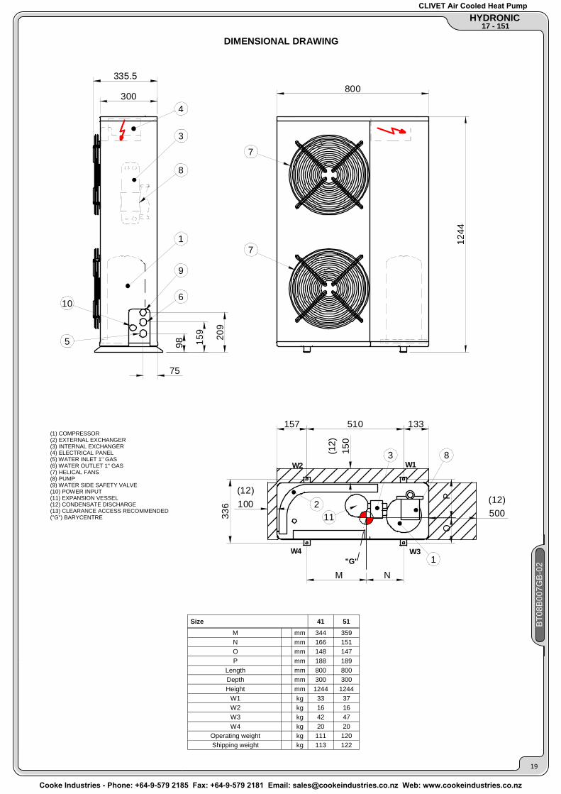
DIMENSIONAL DRAWING
"G"
W2
W4
W1
W3
(12)
150
(12)100 (12)
500
M N
PO
157 510 133
336
300
335.5800
1244
98 159 209
75
1
1
2
3
3
4
5
6
7
7
8
8
9
10
11
(1) COMPRESSOR (2) EXTERNAL EXCHANGER (3) INTERNAL EXCHANGER (4) ELECTRICAL PANEL (5) WATER INLET 1" GAS (6) WATER OUTLET 1" GAS (7) HELICAL FANS (8) PUMP (9) WATER SIDE SAFETY VALVE (10) POWER INPUT (11) EXPANSION VESSEL (12) CONDENSATE DISCHARGE (13) CLEARANCE ACCESS RECOMMENDED ("G") BARYCENTRE
Size 41 51
M mm 344 359 N mm 166 151 O mm 148 147 P mm 188 189
Length mm 800 800 Depth mm 300 300 Height mm 1244 1244
W1 kg 33 37 W2 kg 16 16 W3 kg 42 47 W4 kg 20 20
Operating weight kg 111 120 Shipping weight kg 113 122
BT0
8B00
7GB
-02
19
CLIVET Air Cooled Heat Pump
Cooke Industries - Phone: +64-9-579 2185 Fax: +64-9-579 2181 Email: [email protected] Web: www.cookeindustries.co.nz

HYDRONIC 17 - 151
DIMENSIONAL DRAWING
411
1174
1040
80
344
15 1057 15
"G"
117 823 148
80
150
100
148
365
2020
2
3 4
56
7
488
5
5
8
9
10
3
6
(12) (12)500
(12)
11 11
1
P0
MN
W1
W4
W2
W3
116
13 13
(1) COMPRESSOR (2) ELECTRICAL PANEL (3) INTERNAL EXCHANGER (4) EXTERNAL EXCHANGER (5) HELICAL FANS (6) PUMP (7) EXPANSION VESSEL (8) WATER OUTLET (STANDARD UNIT) (9) WATER INLET (STANDARD UNIT) (10) POWER INPUT (11) CONDENSATE DISCHARGE (12) CLEARANCE ACCESS RECOMMENDED (13) LIFTING HOLES ("G") BARYCENTRE
Size 61 71
M mm 630 632 N mm 427 425 O mm 149 149 P mm 216 216
Length mm 1087 1087 Depth mm 411 411 Height mm 1175 1175
W1 kg 44 46 W2 kg 30 31 W3 kg 31 32 W4 kg 21 21
Operating weight kg 126 129 Shipping weight kg 132 135
BT0
8B00
7GB
-02
20
CLIVET Air Cooled Heat Pump
Cooke Industries - Phone: +64-9-579 2185 Fax: +64-9-579 2181 Email: [email protected] Web: www.cookeindustries.co.nz

17 - 151 HYDRONIC
DIMENSIONAL DRAWING
"G"
2
3
4
5
5
5
6
7
8
9
10
11 11
117 1087 170
1326
370
508
2121
134315 15
556
1225
78
500
150
100
(12)
(12)
(12)
BA
1
7
3
1
N M
OP
86.5
C
27
W1
W4
W2
W3
13 13
81 / 91 101 / 121A mm. 150 175B mm. 555 500
GRANDEZZE
(1) COMPRESSOR (2) ELECTRICAL PANEL (3) INTERNAL EXCHANGER (4) EXTERNAL EXCHANGER (5) HELICAL FANS (6) PUMP (7) EXPANSION VESSEL (8) WATER OUTLET (STANDARD UNIT) (9) WATER INLET (STANDARD UNIT) (10) POWER INPUT (11) CONDENSATE DISCHARGE (12) CLEARANCE ACCESS RECOMMENDED (13) LIFTING HOLES ("G") BARYCENTRE
Size 81 91 101 121
M mm 764 766 758 763 N mm 579 577 585 580 O mm 217 217 228 229 P mm 291 291 280 279
Length mm 1373 1373 1373 1373 Depth mm 555 555 555 555 Height mm 1225 1225 1225 1225
W1 kg 57 58 61 63 W2 kg 43 44 47 48 W3 kg 43 43 50 52 W4 kg 32 33 39 39
Operating weight kg 174 178 198 201 Shipping weight kg 180 184 203 206
BT0
8B00
7GB
-02
21
Size
CLIVET Air Cooled Heat Pump
Cooke Industries - Phone: +64-9-579 2185 Fax: +64-9-579 2181 Email: [email protected] Web: www.cookeindustries.co.nz

HYDRONIC 17 - 151
DIMENSIONAL DRAWING
"G"
1711
1476
78
150 1225 325
174
505
2
7
3
5
5
8
10
9
684
1
6
4
5
670
1700
(11)500
150
100(11)
(11)
1
OP
W1
W4
W2
W3
150 325
2063
020
N M
120
12 12
7
1
63
(1) COMPRESSOR (2) ELECTRICAL PANEL (3) INTERNAL EXCHANGER (4) EXTERNAL EXCHANGER (5) HELICAL FANS (6) PUMP (7) EXPANSION VESSEL (8) WATER OUTLET (STANDARD UNIT) (9) WATER INLET (STANDARD UNIT) (10) POWER INPUT (11) CLEARANCE ACCESS RECOMMENDED (12) LIFTING HOLES ("G") BARYCENTRE
Size 131 151
M mm 703 706 N mm 517 514 O mm 292 292 P mm 378 378
Length mm 1710 1710 Depth mm 684 684 Height mm 1477 1477
W1 kg 94 97 W2 kg 56 57 W3 kg 73 75 W4 kg 44 44
Operating weight kg 268 273 Shipping weight kg 275 280
CLIVET SPAFeltre (BL) ITALYTel. + 39 0439 3131Fax + 39 0439 [email protected]
CLIVET ESPAÑA S.A.Madrid - SPAINTel. + 34 91 6658280Fax + 34 91 [email protected]
CLIVET UK LTDFareham (Hampshire) U.K.Tel. + 44 (0) 1489 572238Fax + 44 (0) 1489 [email protected]
CLIVET NEDERLAND B.V.Amersfoort - NetherlandsTel. + 31 (0) 33 7503420Fax + 31 (0) 33 [email protected]
CLIVET TFAIR SYSTEMS (P)LTD.Malur - INDIATel. +91 8151 232683/5Fax [email protected]
CLIVET SPABUREAU DE LIAISON EN FRANCEVerrierès le Buisson - FRANCETel. + 33 (0)1 69 20 25 75Fax + 33 (0)1 69 20 60 [email protected]
CLIVET GmbHNorderstedt - GERMANYTel. +49 (0) 40 32 59 57-0Fax +49 (0) 40 32 59 [email protected]
The data contained in this bulletin is not binding and may be changed by the manufacturer without prior notice. All reproduction, even partial, is prohibited. © Copyright - CLIVET S.p.A. - Feltre (BL) - Italy
CLIVET Air Cooled Heat Pump
Cooke Industries - Phone: +64-9-579 2185 Fax: +64-9-579 2181 Email: [email protected] Web: www.cookeindustries.co.nz
Related Documents