Cisco Systems, Inc. www.cisco.com Cisco IE 4000 Switch Hardware Installation Guide First Published: September 2015 Last Updated: December 2015

Welcome message from author
This document is posted to help you gain knowledge. Please leave a comment to let me know what you think about it! Share it to your friends and learn new things together.
Transcript
Cisco IE 4000 Switch Hardware Installation GuideFirst Published: September 2015Last Updated: December 2015
Cisco Systems, Inc. www.cisco.com

THE SPECIFICATIONS AND INFORMATION REGARDING THE PRODUCTS IN THIS MANUAL ARE SUBJECT TO CHANGE WITHOUT NOTICE. ALL STATEMENTS, INFORMATION, AND RECOMMENDATIONS IN THIS MANUAL ARE BELIEVED TO BE ACCURATE BUT ARE PRESENTED WITHOUT WARRANTY OF ANY KIND, EXPRESS OR IMPLIED. USERS MUST TAKE FULL RESPONSIBILITY FOR THEIR APPLICATION OF ANY PRODUCTS.THE SOFTWARE LICENSE AND LIMITED WARRANTY FOR THE ACCOMPANYING PRODUCT ARE SET FORTH IN THE INFORMATION PACKET THAT SHIPPED WITH THE PRODUCT AND ARE INCORPORATED HEREIN BY THIS REFERENCE. IF YOU ARE UNABLE TO LOCATE THE SOFTWARE LICENSE OR LIMITED WARRANTY, CONTACT YOUR CISCO REPRESENTATIVE FOR A COPY.The following information is for FCC compliance of Class A devices: This equipment has been tested and found to comply with the limits for a Class A digital device, pursuant to part 15 of the FCC rules. These limits are designed to provide reasonable protection against harmful interference when the equipment is operated in a commercial environment. This equipment generates, uses, and can radiate radio-frequency energy and, if not installed and used in accordance with the instruction manual, may cause harmful interference to radio communications. Operation of this equipment in a residential area is likely to cause harmful interference, in which case users will be required to correct the interference at their own expense. The following information is for FCC compliance of Class B devices: This equipment has been tested and found to comply with the limits for a Class B digital device, pursuant to part 15 of the FCC rules. These limits are designed to provide reasonable protection against harmful interference in a residential installation. This equipment generates, uses and can radiate radio frequency energy and, if not installed and used in accordance with the instructions, may cause harmful interference to radio communications. However, there is no guarantee that interference will not occur in a particular installation. If the equipment causes interference to radio or television reception, which can be determined by turning the equipment off and on, users are encouraged to try to correct the interference by using one or more of the following measures:■ Reorient or relocate the receiving antenna.
■ Increase the separation between the equipment and receiver.
■ Connect the equipment into an outlet on a circuit different from that to which the receiver is connected.
■ Consult the dealer or an experienced radio/TV technician for help.
Modifications to this product not authorized by Cisco could void the FCC approval and negate your authority to operate the product. The Cisco implementation of TCP header compression is an adaptation of a program developed by the University of California, Berkeley (UCB) as part of UCB’s public domain version of the UNIX operating system. All rights reserved. Copyright © 1981, Regents of the University of California. NOTWITHSTANDING ANY OTHER WARRANTY HEREIN, ALL DOCUMENT FILES AND SOFTWARE OF THESE SUPPLIERS ARE PROVIDED “AS IS” WITH ALL FAULTS. CISCO AND THE ABOVE-NAMED SUPPLIERS DISCLAIM ALL WARRANTIES, EXPRESSED OR IMPLIED, INCLUDING, WITHOUT LIMITATION, THOSE OF MERCHANTABILITY, FITNESS FOR A PARTICULAR PURPOSE AND NONINFRINGEMENT OR ARISING FROM A COURSE OF DEALING, USAGE, OR TRADE PRACTICE.IN NO EVENT SHALL CISCO OR ITS SUPPLIERS BE LIABLE FOR ANY INDIRECT, SPECIAL, CONSEQUENTIAL, OR INCIDENTAL DAMAGES, INCLUDING, WITHOUT LIMITATION, LOST PROFITS OR LOSS OR DAMAGE TO DATA ARISING OUT OF THE USE OR INABILITY TO USE THIS MANUAL, EVEN IF CISCO OR ITS SUPPLIERS HAVE BEEN ADVISED OF THE POSSIBILITY OF SUCH DAMAGES.Any Internet Protocol (IP) addresses and phone numbers used in this document are not intended to be actual addresses and phone numbers. Any examples, command display output, network topology diagrams, and other figures included in the document are shown for illustrative purposes only. Any use of actual IP addresses or phone numbers in illustrative content is unintentional and coincidental.All printed copies and duplicate soft copies are considered un-Controlled copies and the original on-line version should be referred to for latest version.Cisco has more than 200 offices worldwide. Addresses, phone numbers, and fax numbers are listed on the Cisco website at www.cisco.com/go/offices.Cisco and the Cisco logo are trademarks or registered trademarks of Cisco and/or its affiliates in the U.S. and other countries. To view a list of Cisco trademarks, go to this URL:www.cisco.com/go/trademarks. Third-party trademarks mentioned are the property of their respective owners. The use of the word partner does not imply a partnership relationshipbetween Cisco and any other company. (1110R)
© 2015 Cisco Systems, Inc. All rights reserved.
ii
PrefaceAudience
This guide is for the networking or computer technician responsible for installing Cisco IE 4000 series switches. We assume that you are familiar with the concepts and terminology of Ethernet and local area networking.
PurposeThis guide documents the hardware features of the Cisco IE 4000 switches. It describes the physical and performance characteristics of each switch, explains how to install a switch, and provides troubleshooting information.
This guide does not describe system messages that you might receive or how to configure your switch. For more information, see the Cisco IE4000 documentation at http://www.cisco.com/en/US/products/ps12451/tsd_products_support_series_home.html
For information about the standard Cisco IOS commands, see http://www.cisco.com/cisco/web/psa/configure.html?mode=prod&level0=268438303
ConventionsThis document uses the following conventions and symbols for notes, cautions, and warnings.
Note: Means reader take note. Notes contain helpful suggestions or references to materials not contained in this manual.
Caution: Means reader be careful. In this situation, you might do something that could result in equipment damage or loss of data.
Warning: This warning symbol means danger. You are in a situation that could cause bodily injury. Before you work on any equipment, be aware of the hazards involved with electrical circuitry and be familiar with standard practices for preventing accidents. Use the statement number provided at the end of each warning to locate its translation in the translated safety warnings that accompanied this device. Statement 1071
The safety warnings for this product are translated into several languages in the Regulatory Compliance and Safety Information for the Cisco IE 4000 Switch that ships with the product. The EMC regulatory statements are also included in that guide.
Related PublicationsBefore installing, configuring, or upgrading the switch, see the release notes on Cisco.com for the latest information.
These documents provide complete information about the switch and are available on Cisco.com:
Regulatory Compliance and Safety Information for the Cisco IE 4000 Switch
Release Notes for the Cisco IE 4000 Switch
iii
Cisco Systems, Inc. www.cisco.com
Preface
Obtaining Documentation, Obtaining Support, and Security Guidelines
Cisco IE 4000 Switch Software Configuration Guide
Device Manager online help (available on the switch)
These compatibility matrix documents are available from this Cisco.com site:
http://www.cisco.com/en/US/products/hw/modules/ps5455/products_device_support_tables_list.html
Cisco Gigabit Ethernet Transceiver Modules Compatibility Matrix (not orderable but available on Cisco.com)
Cisco Small Form-Factor Pluggable Modules Compatibility Matrix (not orderable but available on Cisco.com)
Obtaining Documentation, Obtaining Support, and Security Guidelines
For information on obtaining documentation, obtaining support, providing documentation feedback, security guidelines, and also recommended aliases and general Cisco documents, see the monthly What’s New in Cisco Product Documentation, which also lists all new and revised Cisco technical documentation, at:
http://www.cisco.com/en/US/docs/general/whatsnew/whatsnew.html
iv
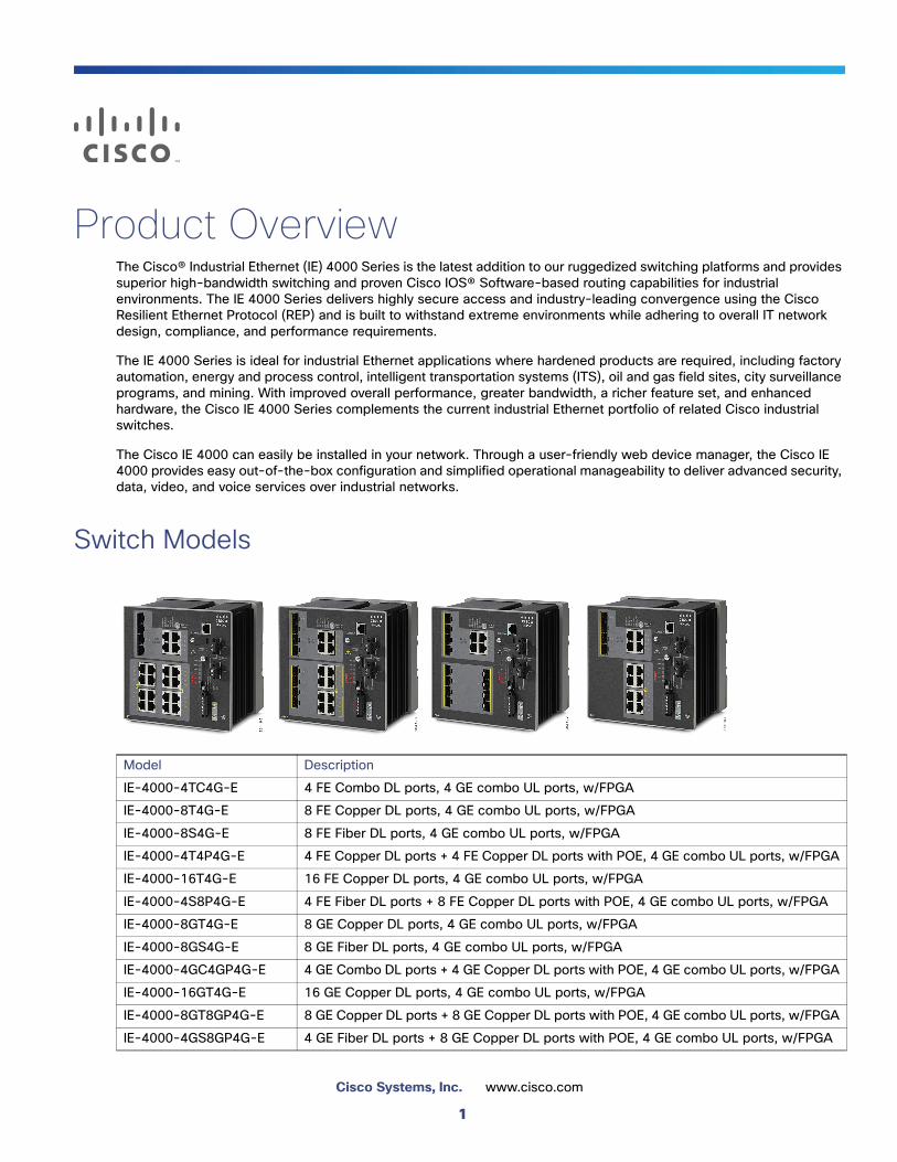
Product OverviewThe Cisco® Industrial Ethernet (IE) 4000 Series is the latest addition to our ruggedized switching platforms and provides superior high-bandwidth switching and proven Cisco IOS® Software-based routing capabilities for industrial environments. The IE 4000 Series delivers highly secure access and industry-leading convergence using the Cisco Resilient Ethernet Protocol (REP) and is built to withstand extreme environments while adhering to overall IT network design, compliance, and performance requirements.
The IE 4000 Series is ideal for industrial Ethernet applications where hardened products are required, including factory automation, energy and process control, intelligent transportation systems (ITS), oil and gas field sites, city surveillance programs, and mining. With improved overall performance, greater bandwidth, a richer feature set, and enhanced hardware, the Cisco IE 4000 Series complements the current industrial Ethernet portfolio of related Cisco industrial switches.
The Cisco IE 4000 can easily be installed in your network. Through a user-friendly web device manager, the Cisco IE 4000 provides easy out-of-the-box configuration and simplified operational manageability to deliver advanced security, data, video, and voice services over industrial networks.
Switch Models
Model Description
IE-4000-4TC4G-E 4 FE Combo DL ports, 4 GE combo UL ports, w/FPGA
IE-4000-8T4G-E 8 FE Copper DL ports, 4 GE combo UL ports, w/FPGA
IE-4000-8S4G-E 8 FE Fiber DL ports, 4 GE combo UL ports, w/FPGA
IE-4000-4T4P4G-E 4 FE Copper DL ports + 4 FE Copper DL ports with POE, 4 GE combo UL ports, w/FPGA
IE-4000-16T4G-E 16 FE Copper DL ports, 4 GE combo UL ports, w/FPGA
IE-4000-4S8P4G-E 4 FE Fiber DL ports + 8 FE Copper DL ports with POE, 4 GE combo UL ports, w/FPGA
IE-4000-8GT4G-E 8 GE Copper DL ports, 4 GE combo UL ports, w/FPGA
IE-4000-8GS4G-E 8 GE Fiber DL ports, 4 GE combo UL ports, w/FPGA
IE-4000-4GC4GP4G-E 4 GE Combo DL ports + 4 GE Copper DL ports with POE, 4 GE combo UL ports, w/FPGA
IE-4000-16GT4G-E 16 GE Copper DL ports, 4 GE combo UL ports, w/FPGA
IE-4000-8GT8GP4G-E 8 GE Copper DL ports + 8 GE Copper DL ports with POE, 4 GE combo UL ports, w/FPGA
IE-4000-4GS8GP4G-E 4 GE Fiber DL ports + 8 GE Copper DL ports with POE, 4 GE combo UL ports, w/FPGA
1
Cisco Systems, Inc. www.cisco.com
Product Overview
Front Panel Overview
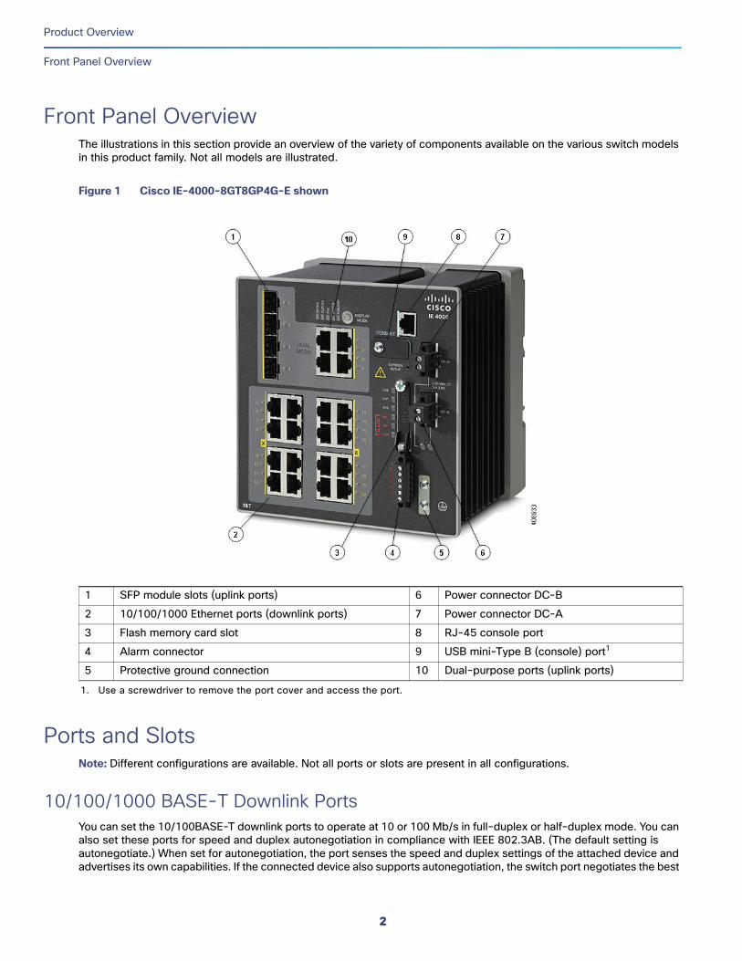
Front Panel OverviewThe illustrations in this section provide an overview of the variety of components available on the various switch models in this product family. Not all models are illustrated.
Figure 1 Cisco IE-4000-8GT8GP4G-E shown
Ports and SlotsNote: Different configurations are available. Not all ports or slots are present in all configurations.
10/100/1000 BASE-T Downlink PortsYou can set the 10/100BASE-T downlink ports to operate at 10 or 100 Mb/s in full-duplex or half-duplex mode. You can also set these ports for speed and duplex autonegotiation in compliance with IEEE 802.3AB. (The default setting is autonegotiate.) When set for autonegotiation, the port senses the speed and duplex settings of the attached device and advertises its own capabilities. If the connected device also supports autonegotiation, the switch port negotiates the best
1 SFP module slots (uplink ports) 6 Power connector DC-B
2 10/100/1000 Ethernet ports (downlink ports) 7 Power connector DC-A
3 Flash memory card slot 8 RJ-45 console port
4 Alarm connector 9 USB mini-Type B (console) port1
1. Use a screwdriver to remove the port cover and access the port.
5 Protective ground connection 10 Dual-purpose ports (uplink ports)
2
Product Overview
Ports and Slots
connection (that is, the fastest line speed that both devices support, and full-duplex transmission if the attached device supports it) and configures itself accordingly. In all cases, the attached device must be within 328 feet (100 meters). 100BASE-TX traffic requires Category 5 cable. 10BASE-T traffic can use Category 3 or Category 4 cables.
When connecting the switch to workstations, servers, routers, and Cisco IP phones, make sure that the cable is a straight-through cable.
You can use the mdix auto interface configuration command in the command-line interface (CLI) to enable the automatic medium-dependent interface crossover (auto-MDIX) feature. When the auto-MDIX feature is enabled, the switch detects the required cable type for copper Ethernet connections and configures the interfaces accordingly. For configuration information for this feature, see the switch software configuration guide or the switch command reference.
10/100/1000BASE-T Uplink PortsThe IEEE 802.3u 10/100/1000BASE-T uplink ports provide full-duplex 10, 100 or 1000 Mb/s connectivity over Category 5 unshielded twisted pair (UTP) copper cabling. The default setting is autonegotiate. The cable can be up to 100 m (0.1 km) in length.
100/1000 Mb/s SFP Module Downlink SlotsThe IEEE 802.3u 100 Mb/s SFP module downlink slots provide full-duplex 100 Mb/s connectivity over multi-mode (MM) fiber cables or single-mode (SM) fiber cables. These ports use a SFP fiber-optic transceiver module that accepts a dual LC connector. Check the SFP specifications for the cable type and length.
100/1000 Mb/s SFP Module Uplink SlotsThe IEEE 802.3u 100 Mb/s SFP module uplink slots provide full-duplex 100 or 1000 Mb/s connectivity over multi-mode (MM) fiber cables or single-mode (SM) fiber cables. These ports use a SFP fiber-optic transceiver module that accepts a dual LC connector. Check the SFP specifications for the cable type and length.
Dual-Purpose Fast Ethernet Downlink PortsYou can configure the dual-purpose Fast Ethernet Downlink ports on the switch as either 10/100BASE-T ports or as 100 Mb/s SFP-module ports. You can set the 10/100 ports to autonegotiate, or you can configure them as fixed 10 or 100 Mb/s ports.
By default, the switch selects the medium for each dual-purpose port (10/100BASE-T or SFP). When a link is achieved on one media type, the switch disables the other media type until the active link goes down. If links are active on both media, the SFP-module port has priority, but you can use the media-type interface configuration command to manually designate the port as an RJ-45 port or an SFP port.
You can configure the speed and duplex settings consistent with the selected media type. For information on configuring interfaces, see the switch software configuration guide.
Dual-Purpose Gigabit Ethernet Uplink or Downlink PortsYou can configure the dual-purpose Gigabit Ethernet uplink or downlink ports on the switch as either 10/1001000BASE-T ports or as 100/1000 Mb/s SFP-module ports. You can set the 10/100/1000BASE-T ports to autonegotiate, or you can configure them as fixed 10, 100, or 1000 Mb/s (Gigabit) Ethernet ports.
By default, the switch selects the medium for each dual-purpose port (10/100/1000BASE-T or SFP). When a link is achieved on one media type, the switch disables the other media type until the active link goes down. If links are active on both media, the SFP-module port has priority, but you can use the media-type interface configuration command to manually designate the port as an RJ-45 port or an SFP port.
3
Product Overview
Power Connectors
You can configure the speed and duplex settings consistent with the selected media type. For information on configuring interfaces, see the switch software configuration guide.
Management PortsYou can connect the switch to a PC running Microsoft Windows or to a terminal server through either the RJ-45 console port or the USB mini-Type B console port, also referred to as the USB-mini console port. These ports use the following connectors:
RJ-45 console port uses an RJ-45-to-DB-9 female cable.
USB-mini console port (5-pin connector) uses a USB Type A-to-5-pin mini-Type B cable.
The USB-mini console interface speeds are the same as the RJ-45 console interface speeds.
To use the USB-mini console port, you must install the Cisco Windows USB device driver on the device that is connected to the USB-mini console port and that is running Microsoft Windows.
Note: For information about downloading the Cisco USB device driver, see Installing the Cisco Microsoft Windows XP, 2000, Vista, 7, 8, and 10 USB Device Driver, page 48.
With the Cisco Windows USB device driver, connecting and disconnecting the USB cable from the console port does not affect Windows HyperTerminal operations. Mac OS X or Linux require no special drivers.
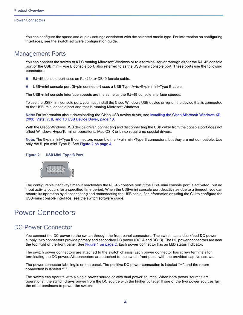
Note: The 5-pin mini-Type B connectors resemble the 4-pin mini-Type B connectors, but they are not compatible. Use only the 5-pin mini-Type B. See Figure 2 on page 4.
Figure 2 USB Mini-Type B Port
The configurable inactivity timeout reactivates the RJ-45 console port if the USB-mini console port is activated, but no input activity occurs for a specified time period. When the USB-mini console port deactivates due to a timeout, you can restore its operation by disconnecting and reconnecting the USB cable. For information on using the CLI to configure the USB-mini console interface, see the switch software guide.
Power Connectors
DC Power ConnectorYou connect the DC power to the switch through the front panel connectors. The switch has a dual-feed DC power supply; two connectors provide primary and secondary DC power (DC-A and DC-B). The DC power connectors are near the top right of the front panel. See Figure 1 on page 2. Each power connector has an LED status indicator.
The switch power connectors are attached to the switch chassis. Each power connector has screw terminals for terminating the DC power. All connectors are attached to the switch front panel with the provided captive screws.
The power connector labeling is on the panel. The positive DC power connection is labeled “+”, and the return connection is labeled “–”.
The switch can operate with a single power source or with dual power sources. When both power sources are operational, the switch draws power from the DC source with the higher voltage. If one of the two power sources fail, the other continues to power the switch.
2531
63
4
Product Overview
Alarm Connector
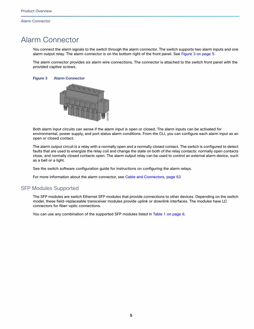
Alarm ConnectorYou connect the alarm signals to the switch through the alarm connector. The switch supports two alarm inputs and one alarm output relay. The alarm connector is on the bottom right of the front panel. See Figure 3 on page 5.
The alarm connector provides six alarm wire connections. The connector is attached to the switch front panel with the provided captive screws.
Figure 3 Alarm Connector
Both alarm input circuits can sense if the alarm input is open or closed. The alarm inputs can be activated for environmental, power supply, and port status alarm conditions. From the CLI, you can configure each alarm input as an open or closed contact.
The alarm output circuit is a relay with a normally open and a normally closed contact. The switch is configured to detect faults that are used to energize the relay coil and change the state on both of the relay contacts: normally open contacts close, and normally closed contacts open. The alarm output relay can be used to control an external alarm device, such as a bell or a light.
See the switch software configuration guide for instructions on configuring the alarm relays.
For more information about the alarm connector, see Cable and Connectors, page 63
SFP Modules SupportedThe SFP modules are switch Ethernet SFP modules that provide connections to other devices. Depending on the switch model, these field-replaceable transceiver modules provide uplink or downlink interfaces. The modules have LC connectors for fiber-optic connections.
You can use any combination of the supported SFP modules listed in Table 1 on page 6.
3312
08
5
Product Overview
LEDs
LEDsYou can use the LEDs to monitor the switch status, activity, and performance. Figure 4 on page 7 and on page 10 show the front panel LEDs.
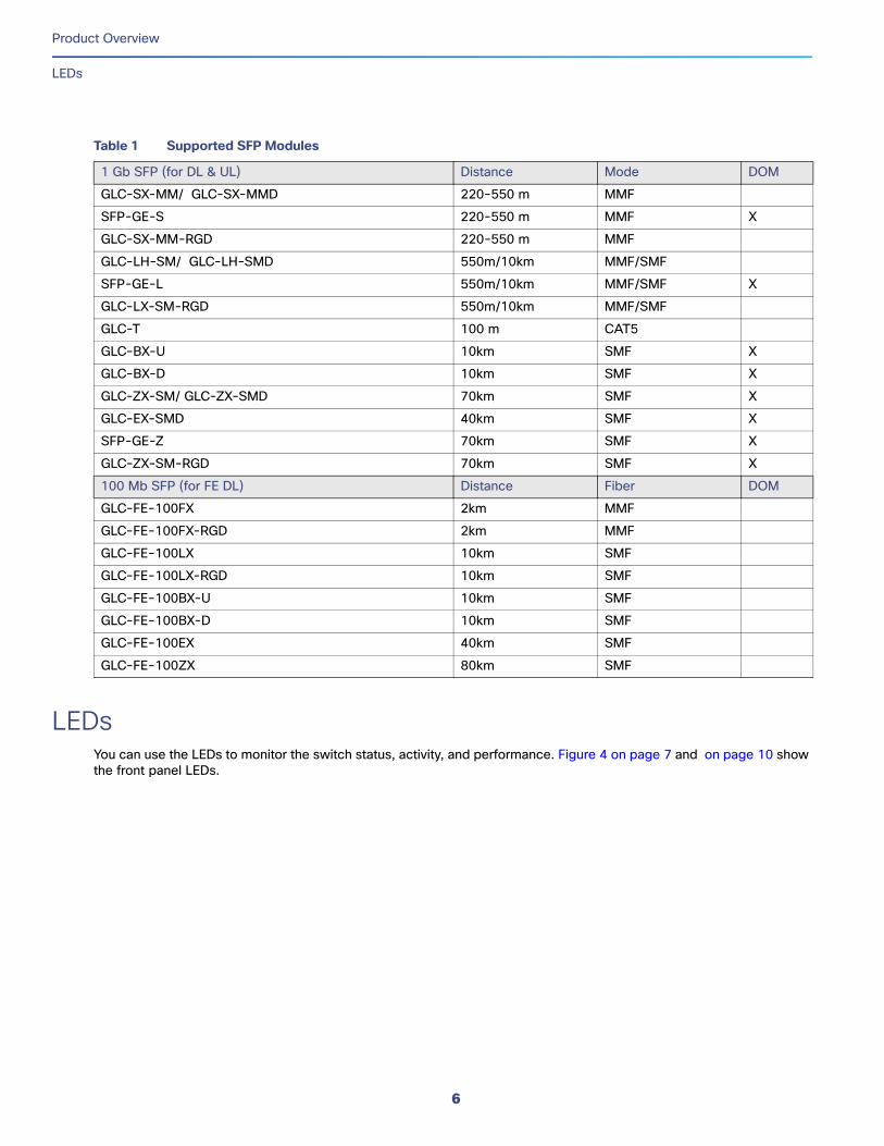
Table 1 Supported SFP Modules
1 Gb SFP (for DL & UL) Distance Mode DOM
GLC-SX-MM/ GLC-SX-MMD 220-550 m MMF
SFP-GE-S 220-550 m MMF X
GLC-SX-MM-RGD 220-550 m MMF
GLC-LH-SM/ GLC-LH-SMD 550m/10km MMF/SMF
SFP-GE-L 550m/10km MMF/SMF X
GLC-LX-SM-RGD 550m/10km MMF/SMF
GLC-T 100 m CAT5
GLC-BX-U 10km SMF X
GLC-BX-D 10km SMF X
GLC-ZX-SM/ GLC-ZX-SMD 70km SMF X
GLC-EX-SMD 40km SMF X
SFP-GE-Z 70km SMF X
GLC-ZX-SM-RGD 70km SMF X
100 Mb SFP (for FE DL) Distance Fiber DOM
GLC-FE-100FX 2km MMF
GLC-FE-100FX-RGD 2km MMF
GLC-FE-100LX 10km SMF
GLC-FE-100LX-RGD 10km SMF
GLC-FE-100BX-U 10km SMF
GLC-FE-100BX-D 10km SMF
GLC-FE-100EX 40km SMF
GLC-FE-100ZX 80km SMF
6
Product Overview
LEDs
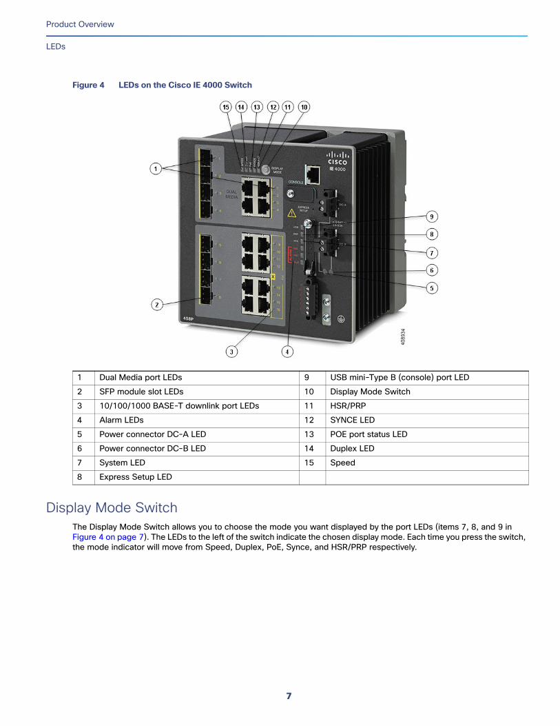
Figure 4 LEDs on the Cisco IE 4000 Switch
Display Mode SwitchThe Display Mode Switch allows you to choose the mode you want displayed by the port LEDs (items 7, 8, and 9 in Figure 4 on page 7). The LEDs to the left of the switch indicate the chosen display mode. Each time you press the switch, the mode indicator will move from Speed, Duplex, PoE, Synce, and HSR/PRP respectively.
1 Dual Media port LEDs 9 USB mini-Type B (console) port LED
2 SFP module slot LEDs 10 Display Mode Switch
3 10/100/1000 BASE-T downlink port LEDs 11 HSR/PRP
4 Alarm LEDs 12 SYNCE LED
5 Power connector DC-A LED 13 POE port status LED
6 Power connector DC-B LED 14 Duplex LED
7 System LED 15 Speed
8 Express Setup LED
7
Product Overview
LEDs
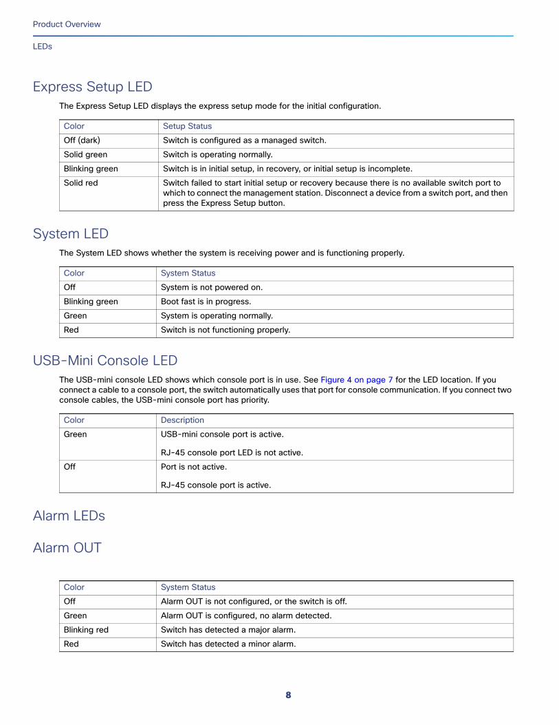
Express Setup LEDThe Express Setup LED displays the express setup mode for the initial configuration.
System LEDThe System LED shows whether the system is receiving power and is functioning properly.
USB-Mini Console LEDThe USB-mini console LED shows which console port is in use. See Figure 4 on page 7 for the LED location. If you connect a cable to a console port, the switch automatically uses that port for console communication. If you connect two console cables, the USB-mini console port has priority.
Alarm LEDs
Alarm OUT
Color Setup Status
Off (dark) Switch is configured as a managed switch.
Solid green Switch is operating normally.
Blinking green Switch is in initial setup, in recovery, or initial setup is incomplete.
Solid red Switch failed to start initial setup or recovery because there is no available switch port to which to connect the management station. Disconnect a device from a switch port, and then press the Express Setup button.
Color System Status
Off System is not powered on.
Blinking green Boot fast is in progress.
Green System is operating normally.
Red Switch is not functioning properly.
Color Description
Green USB-mini console port is active.
RJ-45 console port LED is not active.
Off Port is not active.
RJ-45 console port is active.
Color System Status
Off Alarm OUT is not configured, or the switch is off.
Green Alarm OUT is configured, no alarm detected.
Blinking red Switch has detected a major alarm.
Red Switch has detected a minor alarm.
8
Product Overview
LEDs
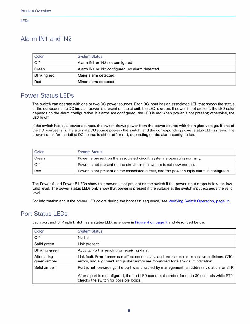
Alarm IN1 and IN2
Power Status LEDsThe switch can operate with one or two DC power sources. Each DC input has an associated LED that shows the status of the corresponding DC input. If power is present on the circuit, the LED is green. If power is not present, the LED color depends on the alarm configuration. If alarms are configured, the LED is red when power is not present; otherwise, the LED is off.
If the switch has dual power sources, the switch draws power from the power source with the higher voltage. If one of the DC sources fails, the alternate DC source powers the switch, and the corresponding power status LED is green. The power status for the failed DC source is either off or red, depending on the alarm configuration.
The Power A and Power B LEDs show that power is not present on the switch if the power input drops below the low valid level. The power status LEDs only show that power is present if the voltage at the switch input exceeds the valid level.
For information about the power LED colors during the boot fast sequence, see Verifying Switch Operation, page 39.
Port Status LEDsEach port and SFP uplink slot has a status LED, as shown in Figure 4 on page 7 and described below.
Color System Status
Off Alarm IN1 or IN2 not configured.
Green Alarm IN1 or IN2 configured, no alarm detected.
Blinking red Major alarm detected.
Red Minor alarm detected.
Color System Status
Green Power is present on the associated circuit, system is operating normally.
Off Power is not present on the circuit, or the system is not powered up.
Red Power is not present on the associated circuit, and the power supply alarm is configured.
Color System Status
Off No link.
Solid green Link present.
Blinking green Activity. Port is sending or receiving data.
Alternating green-amber
Link fault. Error frames can affect connectivity, and errors such as excessive collisions, CRC errors, and alignment and jabber errors are monitored for a link-fault indication.
Solid amber Port is not forwarding. The port was disabled by management, an address violation, or STP.
After a port is reconfigured, the port LED can remain amber for up to 30 seconds while STP checks the switch for possible loops.
9
Product Overview
Flash Memory Card
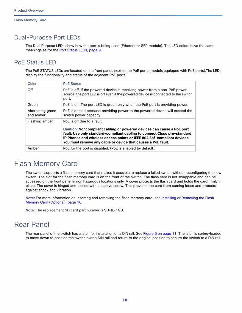
Dual-Purpose Port LEDsThe Dual Purpose LEDs show how the port is being used (Ethernet or SFP module). The LED colors have the same meanings as for the Port Status LEDs, page 9.
PoE Status LEDThe PoE STATUS LEDs are located on the front panel, next to the PoE ports (models equipped with PoE ports).The LEDs display the functionality and status of the adjacent PoE ports.
Flash Memory CardThe switch supports a flash memory card that makes it possible to replace a failed switch without reconfiguring the new switch. The slot for the flash memory card is on the front of the switch. The flash card is hot swappable and can be accessed on the front panel in non hazardous locations only. A cover protects the flash card and holds the card firmly in place. The cover is hinged and closed with a captive screw. This prevents the card from coming loose and protects against shock and vibration.
Note: For more information on inserting and removing the flash memory card, see Installing or Removing the Flash Memory Card (Optional), page 16.
Note: The replacement SD card part number is SD-IE-1GB.
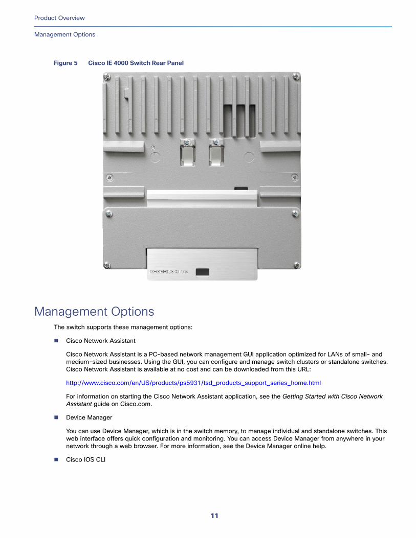
Rear Panel The rear panel of the switch has a latch for installation on a DIN rail. See Figure 5 on page 11. The latch is spring-loaded to move down to position the switch over a DIN rail and return to the original position to secure the switch to a DIN rail.
Color PoE Status
Off PoE is off. If the powered device is receiving power from a non-PoE power source, the port LED is off even if the powered device is connected to the switch port.
Green PoE is on. The port LED is green only when the PoE port is providing power.
Alternating green and amber
PoE is denied because providing power to the powered device will exceed the switch power capacity.
Flashing amber PoE is off due to a fault.
Caution: Noncompliant cabling or powered devices can cause a PoE port fault. Use only standard-compliant cabling to connect Cisco pre-standard IP Phones and wireless access points or IEEE 802.3af-compliant devices. You must remove any cable or device that causes a PoE fault.
Amber PoE for the port is disabled. (PoE is enabled by default.)
10
Product Overview
Management Options
Figure 5 Cisco IE 4000 Switch Rear Panel
Management OptionsThe switch supports these management options:
Cisco Network Assistant
Cisco Network Assistant is a PC-based network management GUI application optimized for LANs of small- and medium-sized businesses. Using the GUI, you can configure and manage switch clusters or standalone switches. Cisco Network Assistant is available at no cost and can be downloaded from this URL:
http://www.cisco.com/en/US/products/ps5931/tsd_products_support_series_home.html
For information on starting the Cisco Network Assistant application, see the Getting Started with Cisco Network Assistant guide on Cisco.com.
Device Manager
You can use Device Manager, which is in the switch memory, to manage individual and standalone switches. This web interface offers quick configuration and monitoring. You can access Device Manager from anywhere in your network through a web browser. For more information, see the Device Manager online help.
Cisco IOS CLI
11
Product Overview
Network Configurations
The switch CLI is based on Cisco IOS software and is enhanced to support desktop-switching features. You can fully configure and monitor the switch. You can access the CLI either by connecting your management station directly to the switch management port, or a console port, or by using Telnet from a remote management station. See the switch command reference on Cisco.com for more information.
SNMP network management
You can manage switches from a SNMP-compatible management station that is running platforms such as HP OpenView or SunNet Manager. The switch supports a comprehensive set of Management Information Base (MIB) extensions and four Remote Monitoring (RMON) groups. See the switch software configuration guide on Cisco.com and the documentation that came with your SNMP application for more information.
Common Industrial Protocol
The Common Industrial Protocol (CIP) management objects are supported. The Cisco IE 4000 can be managed by CIP-based management tools, allowing the user to manage an entire industrial automation system with one tool.
PROFINET TCP/IP and RT
This switch supports PROFINET TCP/IP and RT and can be managed by Siemens' automation software such as STEP 7.
Network ConfigurationsSee the switch software configuration guide on Cisco.com for network configuration concepts and examples of using the switch to create dedicated network segments and interconnecting the segments through Gigabit Ethernet connections.
12
Switch InstallationThis chapter describes how to install your switch, verify the boot fast, and connect the switch to other devices. It also includes information specifically for installations in hazardous environments.
Read these topics, and perform the procedures in this order:
Preparing for Installation, page 13
Installing or Removing the Flash Memory Card (Optional), page 16
Connecting to a Console Port (Optional), page 17
Connecting to Power, page 18
Installing the Switch, page 29
Connecting Alarm Circuits, page 31
Connecting Destination Ports, page 35
Verifying Switch Operation, page 39
Where to Go Next, page 39
Preparing for InstallationThis section provides information about these topics:
Warnings, page 13
Installation Guidelines, page 15
Installation Guidelines, page 15
Verifying Package Contents, page 16
WarningsThese warnings are translated into several languages in the Regulatory Compliance and Safety Information for this switch.
Warning: Before working on equipment that is connected to power lines, remove jewelry (including rings, necklaces, and watches). Metal objects will heat up when connected to power and ground and can cause serious burns or weld the metal object to the terminals. Statement 43
Warning: Exposure to some chemicals could degrade the sealing properties of materials used in the sealed relay device. Statement 381
Warning: Do not work on the system or connect or disconnect cables during periods of lightning activity. Statement 1001
13
Cisco Systems, Inc. www.cisco.com
Switch Installation
Preparing for Installation
Warning: Before performing any of the following procedures, ensure that power is removed from the DC circuit. Statement 1003
Warning: Read the installation instructions before you connect the system to its power source. Statement 1004
Warning: This unit is intended for installation in restricted access areas. A restricted access area can be accessed only through the use of a special tool, lock and key, or other means of security. Statement 1017
Warning: This equipment must be grounded. Never defeat the ground conductor or operate the equipment in the absence of a suitably installed ground conductor. Contact the appropriate electrical inspection authority or an electrician if you are uncertain that suitable grounding is available. Statement 1024
Warning: This unit might have more than one power supply connection. All connections must be removed to de-energize the unit. Statement 1028
Warning: Only trained and qualified personnel should be allowed to install, replace, or service this equipment. Statement 1030
Warning: Ultimate disposal of this product should be handled according to all national laws and regulations. Statement 1040
Warning: For connections outside the building where the equipment is installed, the following ports must be connected through an approved network termination unit with integral circuit protection.10/100/1000 Ethernet Statement 1044
Warning: To prevent the system from overheating, do not operate it in an area that exceeds the maximum recommended ambient temperature of:158°F (70°C) Statement 1047
Warning: In switch installations in a hazardous location, the DC power source could be located away from the vicinity of the switch. Before performing any of the following procedures, locate the DC circuit to ensure that the power is removed and cannot be turned on accidentally, or verify that the area is nonhazardous before proceeding. Statement 1059
Warning: This equipment is supplied as “open type” equipment. It must be mounted within an enclosure that is suitably designed for those specific environmental conditions that will be present and appropriately designed to prevent personal injury resulting from accessibility to live parts. The interior of the enclosure must be accessible only by the use of a tool.
The enclosure must meet IP 54 or NEMA type 4 minimum enclosure rating standards. Statement 1063
Warning: When used in a Class I, Division 2, hazardous location, this equipment must be mounted in a suitable enclosure with proper wiring method, for all power, input and output wiring, that complies with the governing electrical codes and in accordance with the authority having jurisdiction over Class I, Division 2 installations. Statement 1066
Warning: Installation of the equipment must comply with local and national electrical codes. Statement 1074
Warning: Explosion Hazard—The area must be known to be nonhazardous before installing, servicing, or replacing the unit. Statement 1082
Warning: Explosion Hazard—Substitution of components may impair suitability for Class I, Division 2/Zone 2. Statement 1083
Caution: When installed in a Class I, Div/Zone 2 hazardous location environment, this equipment must be installed in a min. IP54, ATEX certified enclosure.
Caution: Airflow around the switch must be unrestricted. To prevent the switch from overheating, there must be the following minimum clearances:– Top and bottom: 2.0 in. (50.8 mm)
14
Switch Installation
Preparing for Installation
– Sides: 2.0 in. (50.8 mm)– Front: 2.0 in. (50.8 mm)Contact your Cisco Technical Assistance Centre (TAC) if tighter spacings are required.
Caution: When installed in a Class I, Div/Zone 2 hazardous location environment, this equipment must be installed in a pollution degree 2 environment per IEC 60664-1)
Caution: This equipment is suitable for use in Class I, Division 2, Groups A, B, C, D, or only nonhazardous locations.
Caution: Airflow around the switch must be unrestricted. To prevent the switch from overheating, there must be the following minimum clearances:– Top and bottom: 2.0 in. (50.8 mm)– Sides: 2.0 in. (50.8 mm)– Front: 2.0 in. (50.8 mm)
Installation GuidelinesWhen determining where to place the switch, observe these guidelines.
Environment and Enclosure GuidelinesReview these environmental and enclosure guidelines before installation:
This equipment is intended for use in a Pollution Degree 2 industrial environment, in overvoltage Category II applications (as defined in IEC publication 60664-1), at altitudes up to 9842 ft (3 km) without derating.
This equipment is considered Group 1, Class A industrial equipment, according to IEC/CISPR Publication 11. Without appropriate precautions, there may be potential difficulties ensuring electromagnetic compatibility in other environments due to conducted as well as radiated disturbance.
This equipment is supplied as open-type equipment. It must be mounted within an enclosure that is suitably designed for those specific environmental conditions that will be present and appropriately designed to prevent personal injury resulting from accessibility to live parts. The enclosure must have suitable flame-retardant properties to prevent or minimize the spread of flame, complying with a flame-spread rating of 5VA, V2, V1, V0 (or equivalent) if nonmetallic. The interior of the enclosure must be accessible only by the use of a tool. Subsequent sections of this publication might contain additional information regarding specific enclosure-type ratings that are required to comply with certain product safety certifications.
General GuidelinesBefore installation, observe these general guidelines:
Caution: Proper ESD protection is required whenever you handle Cisco equipment. Installation and maintenance personnel should be properly grounded by using ground straps to eliminate the risk of ESD damage to the switch.
Do not touch connectors or pins on component boards. Do not touch circuit components inside the switch. When not in use, store the equipment in appropriate static-safe packaging.
If you are responsible for the application of safety-related programmable electronic systems (PES), you need to be aware of the safety requirements in the application of the system and be trained in using the system.
This product is grounded through the DIN rail to chassis ground. Use zinc-plated yellow-chromate steel DIN rail to assure proper grounding. The use of other DIN rail materials (such as aluminum, plastic, and so on) that can corrode, oxidize, or are poor conductors can result in improper or intermittent grounding. Secure the DIN rail to the mounting surface approximately every 7.8 in. (200 mm), and use end-anchors appropriately.
When determining where to place the switch, observe these guidelines:
15
Switch Installation
Installing or Removing the Flash Memory Card (Optional)
Before installing the switch, first verify that the switch is operational by powering it on and observing boot fast. Follow the procedures in the Verifying Switch Operation, page 39.
For 10/100 ports and 10/100/1000 ports, the cable length from a switch to an attached device cannot exceed 328 feet (100 meters).
For 100BASE-FX fiber-optic ports, the cable length from a switch to an attached device cannot exceed 6562 ft (2 km).
Clearance to front and rear panels meets these conditions:
— Front-panel LEDs can be easily read.
— Access to ports is sufficient for unrestricted cabling.
— Front-panel direct current (DC) power connectors and the alarm connector are within reach of the connection to the DC power source.
Airflow around the switch must be unrestricted. To prevent the switch from overheating, you must have the following minimum clearances:
— Top and bottom: 2.0 in. (50.8 mm)
— Sides: 2.0 in. (50.8 mm)
— Front: 2.0 in. (50.8 mm)
Caution: When the switch is installed in an industrial enclosure, the temperature within the enclosure is greater than normal room temperature outside the enclosure.
Ensure temperatures inside the enclosure conform to device specifications detailed in Table 3 on page 59.
Cabling is away from sources of electrical noise, such as radios, power lines, and fluorescent lighting fixtures.
Verifying Package ContentsIf any item is missing or damaged, contact your Cisco representative or reseller for support.
Installing or Removing the Flash Memory Card (Optional)The software/firmware is stored on the SD card memory from factory default. Optionally, you can execute the sync command to copy the software/firmware (including directory) to on-board memory (flash memory), then remove the SD card. it is strongly recommended that you use the SD card to boot or store the config for future easy replacement, in case of a hardware failure.
Warning: Do not insert or remove the flash card while power is on; an electrical arc can occur. This could cause an explosion in hazardous location installations. Be sure that power is removed or the area is nonhazardous before proceeding. Statement 379
To install or replace the flash memory card, follow these steps:
1. On the front of the switch, locate the door that protects the flash memory card slot. Loosen the captive screw at the top of the door using a Phillips screwdriver to open the door. See Figure 6 on page 17.
16
Switch Installation
Connecting to a Console Port (Optional)
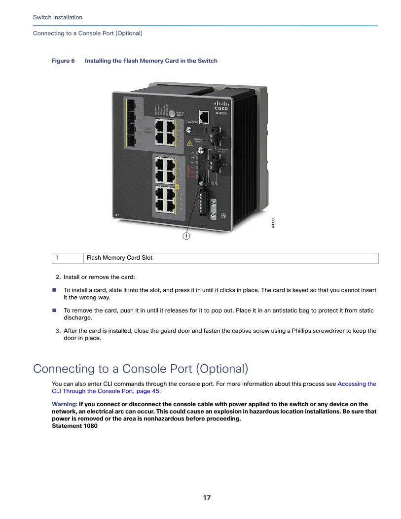
Figure 6 Installing the Flash Memory Card in the Switch
2. Install or remove the card:
To install a card, slide it into the slot, and press it in until it clicks in place. The card is keyed so that you cannot insert it the wrong way.
To remove the card, push it in until it releases for it to pop out. Place it in an antistatic bag to protect it from static discharge.
3. After the card is installed, close the guard door and fasten the captive screw using a Phillips screwdriver to keep the door in place.
Connecting to a Console Port (Optional)You can also enter CLI commands through the console port. For more information about this process see Accessing the CLI Through the Console Port, page 45.
Warning: If you connect or disconnect the console cable with power applied to the switch or any device on the network, an electrical arc can occur. This could cause an explosion in hazardous location installations. Be sure that power is removed or the area is nonhazardous before proceeding.Statement 1080
1 Flash Memory Card Slot
17
Switch Installation
Connecting to Power
Connecting to Power
Tools and EquipmentObtain these necessary tools and equipment:
Ratcheting torque flathead screwdriver that exerts up to 18 in-lb (2.03 N-m) of pressure.
For the protective ground connector, obtain a single or pair of stu size 6 ring terminals (such as Hollingsworth part number R3456B or equivalent).
Crimping tool (such as Thomas & Bett part number WT4000, ERG-2001, or equivalent).
10-gauge copper ground wire.
For DC power connections, use UL- and CSA-rated, style 1007 or 1569 twisted-pair copper appliance wiring material (AWM) wire.
Wire-stripping tools for stripping 10- and 18-gauge wires.
A number-2 Phillips screwdriver.
A flat-blade screwdriver.
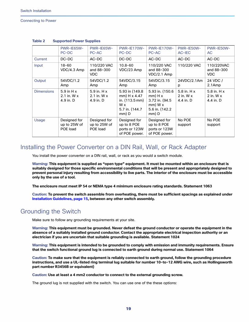
Supported Power SuppliesThe supported power supplies are listed in Table 2 on page 19.
18
Switch Installation
Connecting to Power
Installing the Power Converter on a DIN Rail, Wall, or Rack AdapterYou install the power converter on a DIN rail, wall, or rack as you would a switch module.
Warning: This equipment is supplied as “open type” equipment. It must be mounted within an enclosure that is suitably designed for those specific environmental conditions that will be present and appropriately designed to prevent personal injury resulting from accessibility to live parts. The interior of the enclosure must be accessible only by the use of a tool.
The enclosure must meet IP 54 or NEMA type 4 minimum enclosure rating standards. Statement 1063
Caution: To prevent the switch assemble from overheating, there must be sufficient spacings as explained under Installation Guidelines, page 15, between any other switch assembly.
Grounding the SwitchMake sure to follow any grounding requirements at your site.
Warning: This equipment must be grounded. Never defeat the ground conductor or operate the equipment in the absence of a suitably installed ground conductor. Contact the appropriate electrical inspection authority or an electrician if you are uncertain that suitable grounding is available. Statement 1024
Warning: This equipment is intended to be grounded to comply with emission and immunity requirements. Ensure that the switch functional ground lug is connected to earth ground during normal use. Statement 1064
Caution: To make sure that the equipment is reliably connected to earth ground, follow the grounding procedure instructions, and use a UL-listed ring terminal lug suitable for number 10-to-12 AWG wire, such as Hollingsworth part number R3456B or equivalent)
Caution: Use at least a 4 mm2 conductor to connect to the external grounding screw.
The ground lug is not supplied with the switch. You can use one of the these options:
Table 2 Supported Power Supplies
PWR-IE65W-PC-DC
PWR-IE65W-PC-AC
PWR-IE170W-PC-DC
PWR-IE170W-PC-AC
PWR-IE50W-AC-IEC
PWR-IE50W-AC
Current DC-DC AC-DC DC-DC AC-DC AC-DC AC-DC
Input 18-60 VDC/4.3 Amp
110/220 VAC and 88-300 VDC
10.8-60 VDC/23 Amp
110/220 VAC and 88-300 VDC/2.1 Amp
110/220 VAC 110/220VAC and 88-300 VDC
Output 54VDC/1.2 Amp
54VDC/1.2 Amp
54VDC/3.15 Amp
54VDC/3.15 Amp
24VDC/2.1Amp
24 VDC / 2.1Amp
Dimensions 5.9 in H x 2.1 in. W x 4.9 in. D
5.9 in. H x 2.1 in. W x 4.9 in. D
5.93 in (149.8 mm) H x 4.47 in. (113.5 mm) W x 5.7 in. (144.7 mm) D
5.93 in. (150.6mm) H x 3.72 in. (94.5mm) W x 5.6 in. (142.2mm) D
5.8 in. H x 2 in. W x 4.4 in. D
5.8 in. H x 2 in. W x 4.4 in. D
Usage Designed for up to 25W of POE load
Designed for up to 25W of POE load
Designed for up to 8 POE ports or 123W of POE power.
Designed for up to 8 POE ports or 123W of POE power.
No POE support
No POE support
19
Switch Installation
Connecting to Power
Single ring terminal
Two single ring terminals
To ground the switch to earth ground by using the ground screw, follow these steps:
1. Use a standard Phillips screwdriver or a ratcheting torque screwdriver with a Phillips head to remove the ground screw from the front panel of the switch. Store the ground screw for later use.
2. Use the manufacturer’s guidelines to determine the wire length to be stripped.
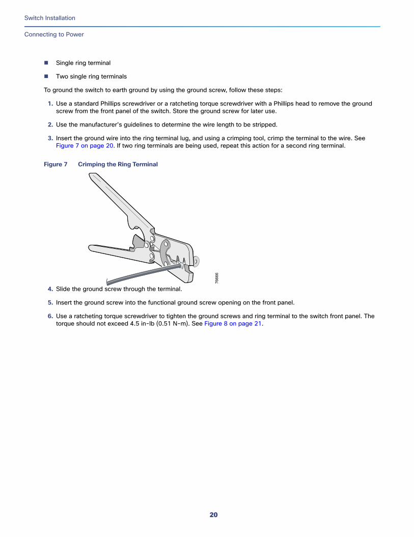
3. Insert the ground wire into the ring terminal lug, and using a crimping tool, crimp the terminal to the wire. See Figure 7 on page 20. If two ring terminals are being used, repeat this action for a second ring terminal.
Figure 7 Crimping the Ring Terminal
4. Slide the ground screw through the terminal.
5. Insert the ground screw into the functional ground screw opening on the front panel.
6. Use a ratcheting torque screwdriver to tighten the ground screws and ring terminal to the switch front panel. The torque should not exceed 4.5 in-lb (0.51 N-m). See Figure 8 on page 21.
7666
6
20
Switch Installation
Connecting to Power
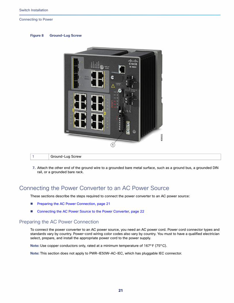
Figure 8 Ground-Lug Screw
7. Attach the other end of the ground wire to a grounded bare metal surface, such as a ground bus, a grounded DIN rail, or a grounded bare rack.
Connecting the Power Converter to an AC Power SourceThese sections describe the steps required to connect the power converter to an AC power source:
Preparing the AC Power Connection, page 21
Connecting the AC Power Source to the Power Converter, page 22
Preparing the AC Power ConnectionTo connect the power converter to an AC power source, you need an AC power cord. Power cord connector types and standards vary by country. Power-cord wiring color codes also vary by country. You must to have a qualified electrician select, prepare, and install the appropriate power cord to the power supply.
Note: Use copper conductors only, rated at a minimum temperature of 167°F (75°C).
Note: This section does not apply to PWR-IE50W-AC-IEC, which has pluggable IEC connector.
1 Ground-Lug Screw
21
Switch Installation
Connecting to Power
Connecting the AC Power Source to the Power ConverterCaution: AC power sources must be dedicated AC branch circuits. Each branch circuit must be protected by a dedicated two-pole circuit breaker.
Caution: Do not turn on AC power until the wiring is secured.
1. Remove the plastic cover from the input power terminals and set it aside.
2. Insert the exposed ground wire lead (10-to-12 AWG cable) into the power converter ground wire connection. Ensure that only wire with insulation extends from the connector. Note that the position of the power converter may vary on different switch models.
3. Tighten the ground wire terminal block screw.
Note: Torque to 10 in-lb (1.13Nm).
4. Insert the line and neutral wire leads into the terminal block line and neutral connections. Make sure that you cannot see any wire lead. Ensure that only wire with insulation extends from the connectors.
5. Tighten the line and neutral terminal block screws.
Note: Torque to 10 in-lb (1.13Nm).
6. Replace the plastic cover over the terminal block.
7. Connect the other end of the wiring to your AC power source.
Connecting the Power Converter to a DC Power SourceYou can also connect the power converter to a DC power source. Several power supplies can be used. Refer to Table 2 on page 19 for the appropriate DC input ratings.
Note: Use copper conductors only, rated at a minimum temperature of 167°F (75°C).
1. Measure a single length of stranded copper wire long enough to connect the power converter to the earth ground. The wire color might differ depending on the country that you are using it in.
For connections from the power converter to earth ground, use shielded 14-AWG stranded copper wire.
2. Measure a length of twisted-pair copper wire long enough to connect the power converter to the DC power source.
For DC connections from the power converter to the DC source, use 10-AWG twisted-pair copper wire.
3. Using a 18-gauge wire-stripping tool, strip the ground wire and both ends of the twisted pair wires to 0.25 inch (6.3 mm) ± 0.02 inch (0.5 mm). Do not strip more than 0.27 inch (6.8 mm) of insulation from the wires. Stripping more than the recommended amount of wire can leave exposed wire from the power and relay connector after installation.
4. Connect one end of the stranded copper wire to a grounded bare metal surface, such as a ground bus, a grounded DIN rail, or a grounded bare rack.
5. Insert the other end of the exposed ground wire lead into the earth-ground wire connection on the power converter terminal block. Note that the position of the power converter may vary on different switch models.
6. Tighten the earth-ground wire connection terminal block screw.
Note: Torque to 8 in.-lb, not to exceed 10 in-lb.
22
Switch Installation
Connecting to Power
Warning: An exposed wire lead from a DC-input power source can conduct harmful levels of electricity. Be sure that no exposed portion of the DC-input power source wire extends from the power and relay connector. Statement 122
7. Insert the twisted-pair wire leads into the terminal block line and neutral connections. Insert the wire (labeled number 1 in Figure 8 on page 21) lead into the neutral wire connection and the wire (labeled number 2 in Figure 8 on page 21) lead into the line wire connection. Ensure that only wire with insulation extends from the connectors. See Figure 8 on page 21.
8. Tighten the line and neutral terminal block screws.
Note: Torque to 8 in.-lb, not to exceed 10 in-lb.
9. Connect the red wire to the positive pole of the DC power source, and connect the black wire to the return pole. Ensure that each pole has a current-limiting-type fuse rated to 30 Amp.
Wiring the DC Power SourceRead these cautions and warnings before wiring the switch the DC power source.
Warning: A readily accessible two-poled disconnect device must be incorporated in the fixed wiring. Statement 1022
Warning: This product relies on the building’s installation for short-circuit (overcurrent) protection. Ensure that the protective device is rated not greater than: 3A. Statement 1005
Warning: Installation of the equipment must comply with local and national electrical codes. Statement 1074
Warning: Before performing any of the following procedures, ensure that power is removed from the DC circuit. Statement 1003
Warning: Only trained and qualified personnel should be allowed to install, replace, or service this equipment. Statement 1030
Caution: For wire connections to the power and alarm connectors, you must use UL- and CSA-rated, style 1007 or 1569 twisted-pair copper appliance wiring material (AWM) wire (such as Belden part number 9318).
To wire the switch to a DC power source, follow these steps:
1. Locate the two power connectors on the switch front panel labeled DC-A and DC-B.
2. Identify the connector positive and return DC power connections. The labels for power connectors DC-A and DC-B are on the switch panel as displayed below.
3. Measure two strands of twisted-pair copper wire (16-to-18 AWG) long enough to connect to the DC power source.
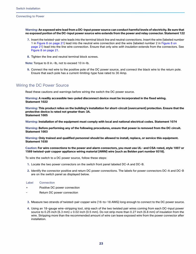
4. Using an 18-gauge wire-stripping tool, strip each of the two twisted pair wires coming from each DC-input power source to 0.25 inch (6.3 mm) ± 0.02 inch (0.5 mm). Do not strip more than 0.27 inch (6.8 mm) of insulation from the wire. Stripping more than the recommended amount of wire can leave exposed wire from the power connector after installation.
Label Connection
+ Positive DC power connection
– Return DC power connection
23
Switch Installation
Connecting to Power
Figure 9 Stripping the Power Connection Wire
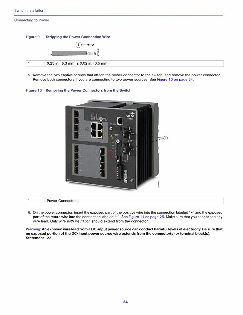
5. Remove the two captive screws that attach the power connector to the switch, and remove the power connector. Remove both connectors if you are connecting to two power sources. See Figure 10 on page 24.
Figure 10 Removing the Power Connectors from the Switch
6. On the power connector, insert the exposed part of the positive wire into the connection labeled “+” and the exposed part of the return wire into the connection labeled “–”. See Figure 11 on page 25. Make sure that you cannot see any wire lead. Only wire with insulation should extend from the connector.
Warning: An exposed wire lead from a DC-input power source can conduct harmful levels of electricity. Be sure that no exposed portion of the DC-input power source wire extends from the connector(s) or terminal block(s). Statement 122
97
48
9
1
1 0.25 in. (6.3 mm) ± 0.02 in. (0.5 mm)
1 Power Connectors
24
Switch Installation
Connecting to Power
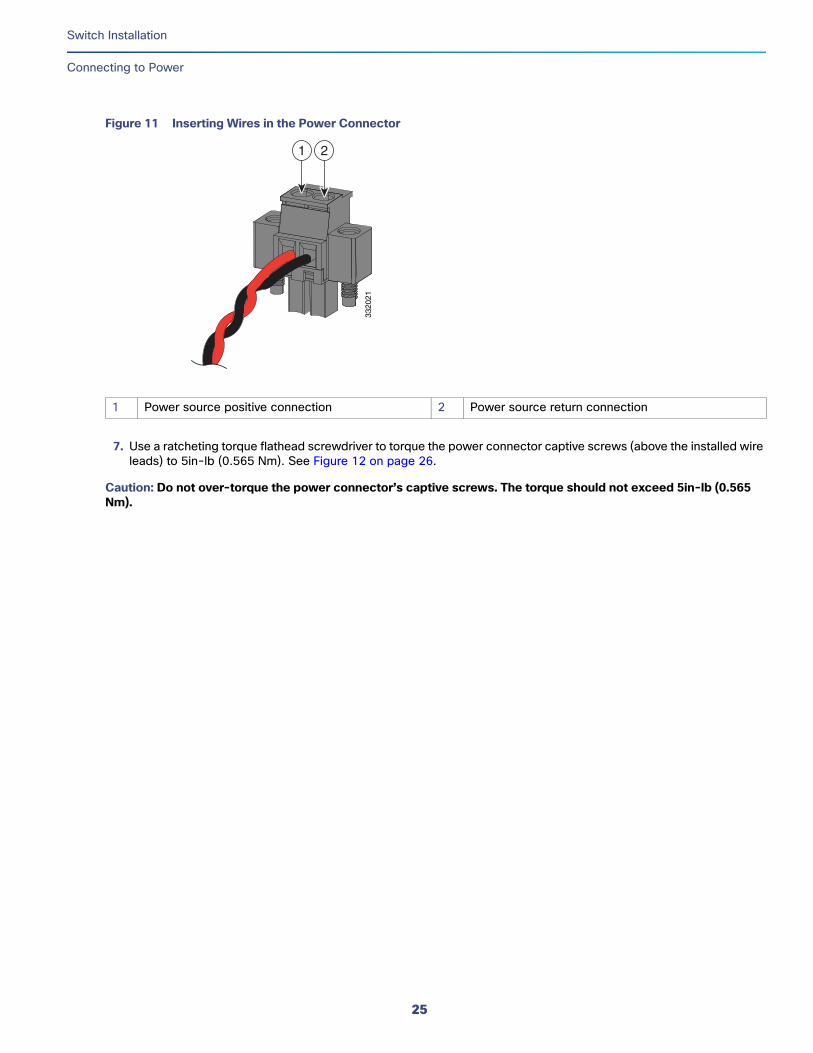
Figure 11 Inserting Wires in the Power Connector
7. Use a ratcheting torque flathead screwdriver to torque the power connector captive screws (above the installed wire leads) to 5in-lb (0.565 Nm). See Figure 12 on page 26.
Caution: Do not over-torque the power connector’s captive screws. The torque should not exceed 5in-lb (0.565 Nm).
1 Power source positive connection 2 Power source return connection
3320
21
1 2
25
Switch Installation
Connecting to Power
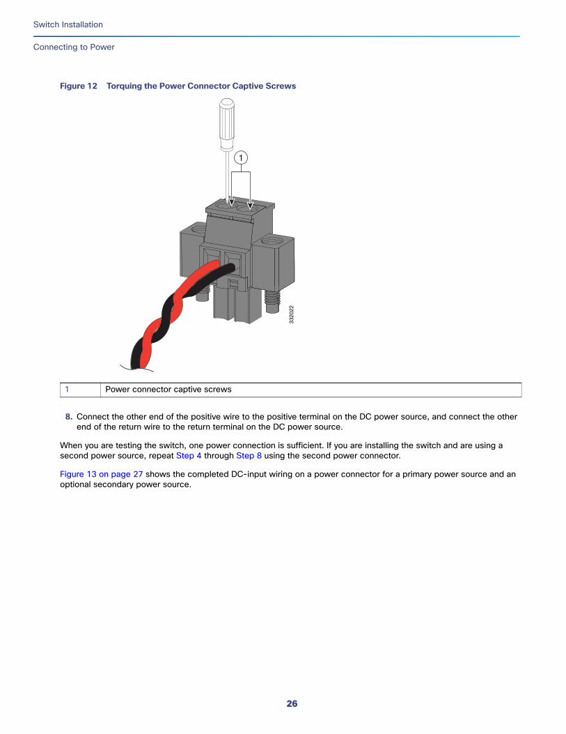
Figure 12 Torquing the Power Connector Captive Screws
8. Connect the other end of the positive wire to the positive terminal on the DC power source, and connect the other end of the return wire to the return terminal on the DC power source.
When you are testing the switch, one power connection is sufficient. If you are installing the switch and are using a second power source, repeat Step 4 through Step 8 using the second power connector.
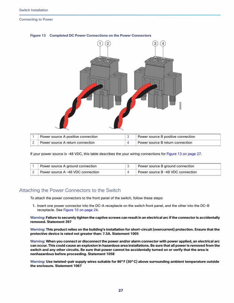
Figure 13 on page 27 shows the completed DC-input wiring on a power connector for a primary power source and an optional secondary power source.
1 Power connector captive screws
3320
22
1
26
Switch Installation
Connecting to Power
Figure 13 Completed DC Power Connections on the Power Connectors
If your power source is –48 VDC, this table describes the your wiring connections for Figure 13 on page 27.
Attaching the Power Connectors to the SwitchTo attach the power connectors to the front panel of the switch, follow these steps:
1. Insert one power connector into the DC-A receptacle on the switch front panel, and the other into the DC-B receptacle. See Figure 10 on page 24.
Warning: Failure to securely tighten the captive screws can result in an electrical arc if the connector is accidentally removed. Statement 397
Warning: This product relies on the building’s installation for short-circuit (overcurrent) protection. Ensure that the protective device is rated not greater than: 7.5A. Statement 1005
Warning: When you connect or disconnect the power and/or alarm connector with power applied, an electrical arc can occur. This could cause an explosion in hazardous area installations. Be sure that all power is removed from the switch and any other circuits. Be sure that power cannot be accidentally turned on or verify that the area is nonhazardous before proceeding. Statement 1058
Warning: Use twisted-pair supply wires suitable for 86°F (30°C) above surrounding ambient temperature outside the enclosure. Statement 1067
1 Power source A positive connection 3 Power source B positive connection
2 Power source A return connection 4 Power source B return connection
1 Power source A ground connection 3 Power source B ground connection
2 Power source A –48 VDC connection 4 Power source B –48 VDC connection
3320
23
1 2 3 4
27
Switch Installation
Connecting to Power
Warning: Installation of the equipment must comply with local and national electrical codes. Statement 1074
2. Use a ratcheting torque flathead screwdriver to tighten the captive screws on the sides of the power connectors.
When you are testing the switch, one power source is sufficient. If you are installing the switch and are using a second power source, repeat this procedure for the second power connector (DC-B), which installs just below the primary power connector (DC-A).
When you are installing the switch, secure the wires coming from the power connector so that they cannot be disturbed by casual contact. For example, use tie wraps to secure the wires to the rack.
Applying Power to the Power ConverterMove the circuit breaker for the AC outlet or the DC control circuit to the on position.
The LED on the power converter front panel is green when the unit is operating normally. The LED is off when the unit is not powered or is not operating normally. After the power is connected, the switch automatically begins the power-on self- test (POST), a series of tests that verifies that the switch functions properly.
Running Boot FastWhen the switch powers on, it automatically initiates a boot fast sequence. To test the switch, follow the steps in these sections:
Powering On the Switch, page 28
Verifying Boot Fast, page 28
Disconnecting Power, page 28
Powering On the SwitchTo apply power to a switch that is directly connected to a DC power source, locate the circuit breaker on the panel board that services the DC circuit, and switch the circuit breaker to the ON position.
Verifying Boot FastWhen you power on the switch, it automatically begins a boot fast sequence. The System LED blinks green as the Cisco IOS software image loads. If the boot fast sequence fails, the System LED turns red.
Note: Boot fast failures are usually fatal. Call Cisco TAC immediately if your switch does not complete boot fast successfully.
Note: You can disable the boot fast and run POST by using the Cisco IOS CLI. See the Cisco IE 4000 Switch Software Configuration Guide for more information.
Disconnecting PowerTo disconnect power after successfully running boot fast, follow these steps:
1. Turn off power to the switch.
2. Disconnect the cables.
28
Switch Installation
Installing the Switch
Installing the SwitchThis section describes how to install the switch:
Installing the Switch on a DIN Rail, page 29
Removing the Switch from a DIN Rail, page 30
Warning: This equipment is supplied as “open type” equipment. It must be mounted within an enclosure that is suitably designed for those specific environmental conditions that will be present and appropriately designed to prevent personal injury resulting from accessibility to live parts. The interior of the enclosure must be accessible only by the use of a tool.
The enclosure must meet IP 54 or NEMA type 4 minimum enclosure rating standards. Statement 1063
Warning: When used in a Class I, Division 2, hazardous location, this equipment must be mounted in a suitable enclosure with proper wiring method, for all power, input and output wiring, that complies with the governing electrical codes and in accordance with the authority having jurisdiction over Class I, Division 2 installations. Statement 1066
Caution: To prevent the switch from overheating, ensure these minimum clearances:– Top and bottom: 2.0 in. (50.8 mm)– Exposed side (not connected to the module): 2.0 in. (50.8 mm) – Front: 2.0 in. (50.8 mm)
Installing the Switch on a DIN RailThe switch ships with a spring-loaded latch on the rear panel for a mounting on a DIN rail.
You can install the switch as a standalone device on the DIN rail or with the expansion modules already connected. You must connect expansion modules to the switch before installing the switch on the DIN rail.
To attach the switch to a DIN rail, follow these steps:
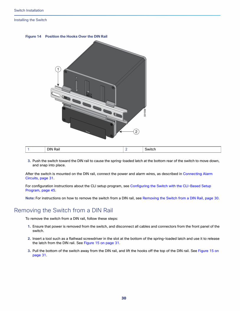
1. Position the rear panel of the switch directly in front of the DIN rail, making sure that the DIN rail fits in the space between the two hooks near the top of the switch and the spring-loaded latch near the bottom.
2. Holding the bottom of the switch away from the DIN rail, place the two hooks on the back of the switch over the top of the DIN rail.
Caution: Do not stack any equipment on the switch.
29
Switch Installation
Installing the Switch
Figure 14 Position the Hooks Over the DIN Rail
3. Push the switch toward the DIN rail to cause the spring-loaded latch at the bottom rear of the switch to move down, and snap into place.
After the switch is mounted on the DIN rail, connect the power and alarm wires, as described in Connecting Alarm Circuits, page 31.
For configuration instructions about the CLI setup program, see Configuring the Switch with the CLI-Based Setup Program, page 45.
Note: For instructions on how to remove the switch from a DIN rail, see Removing the Switch from a DIN Rail, page 30.
Removing the Switch from a DIN Rail To remove the switch from a DIN rail, follow these steps:
1. Ensure that power is removed from the switch, and disconnect all cables and connectors from the front panel of the switch.
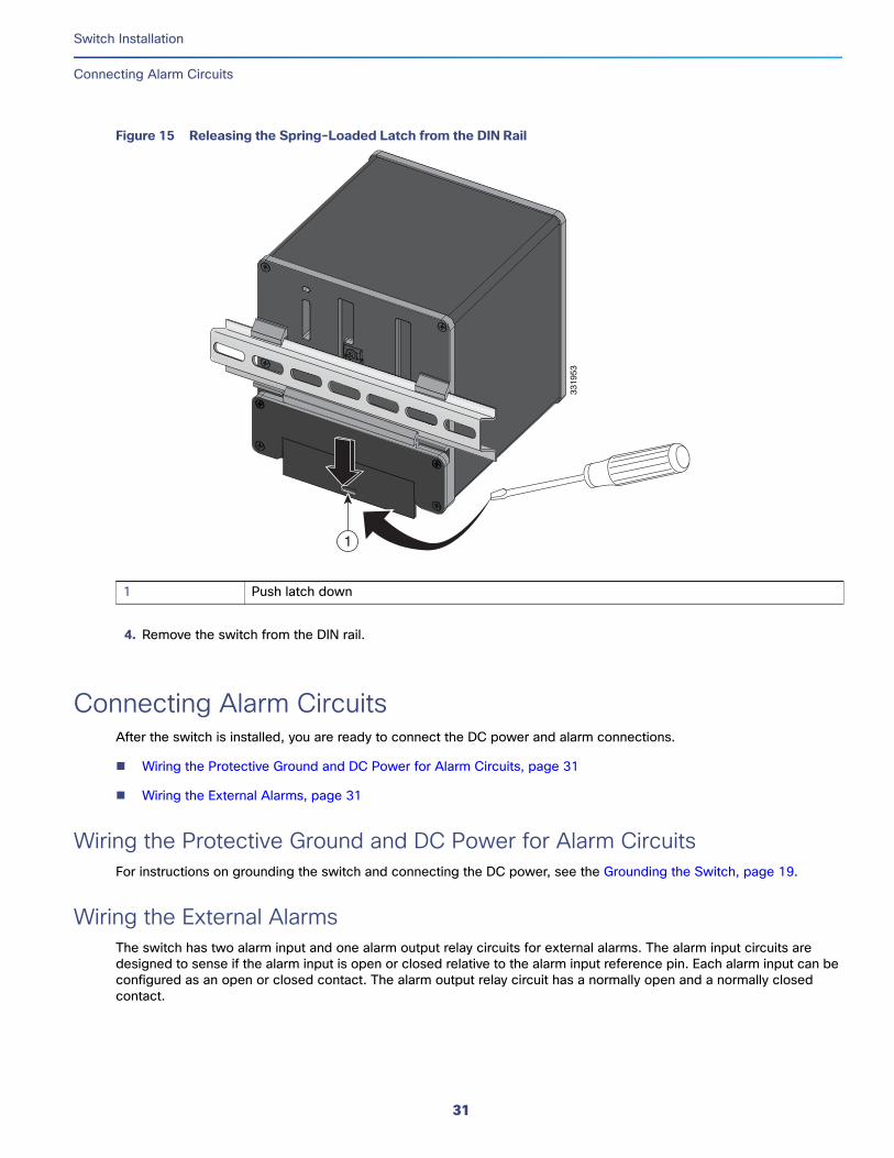
2. Insert a tool such as a flathead screwdriver in the slot at the bottom of the spring-loaded latch and use it to release the latch from the DIN rail. See Figure 15 on page 31.
3. Pull the bottom of the switch away from the DIN rail, and lift the hooks off the top of the DIN rail. See Figure 15 on page 31.
1 DIN Rail 2 Switch33
1556
1
2
30
Switch Installation
Connecting Alarm Circuits
Figure 15 Releasing the Spring-Loaded Latch from the DIN Rail
4. Remove the switch from the DIN rail.
Connecting Alarm CircuitsAfter the switch is installed, you are ready to connect the DC power and alarm connections.
Wiring the Protective Ground and DC Power for Alarm Circuits, page 31
Wiring the External Alarms, page 31
Wiring the Protective Ground and DC Power for Alarm CircuitsFor instructions on grounding the switch and connecting the DC power, see the Grounding the Switch, page 19.
Wiring the External AlarmsThe switch has two alarm input and one alarm output relay circuits for external alarms. The alarm input circuits are designed to sense if the alarm input is open or closed relative to the alarm input reference pin. Each alarm input can be configured as an open or closed contact. The alarm output relay circuit has a normally open and a normally closed contact.
1 Push latch down33
1953
1
31
Switch Installation
Connecting Alarm Circuits
Alarm signals are connected to the switch through the six-pin alarm connector. Three connections are dedicated to the two alarm input circuits: alarm input 1, alarm input 2, and a reference ground. An alarm input and the reference ground wiring connection are required to complete a single alarm input circuit. The three remaining connections are for the alarm output circuit: a normally open output, a normally closed output, and a common signal. An alarm output and the common wiring connection are required to complete a single alarm output circuit.
The labels for the alarm connector are on the switch panel and are displayed below.
Warning: Explosion Hazard—Do not connect or disconnect wiring while the field-side power is on; an electrical arc can occur. This could cause an explosion in hazardous location installations. Be sure that power is removed or that the area is nonhazardous before proceeding. Statement 1081
Caution: The input voltage source of the alarm output relay circuit must be an isolated source and limited to less than or equal to 24 VDC, 1.0 A or 48 VDC, 0.5 A.
Note: Wire connections to the power and alarm connectors must be UL- and CSA-rated, style 1007 or 1569 twisted-pair copper appliance wiring material (AWM) wire (such as Belden part number 9318).
To wire the switch to an external alarm device, follow these steps:
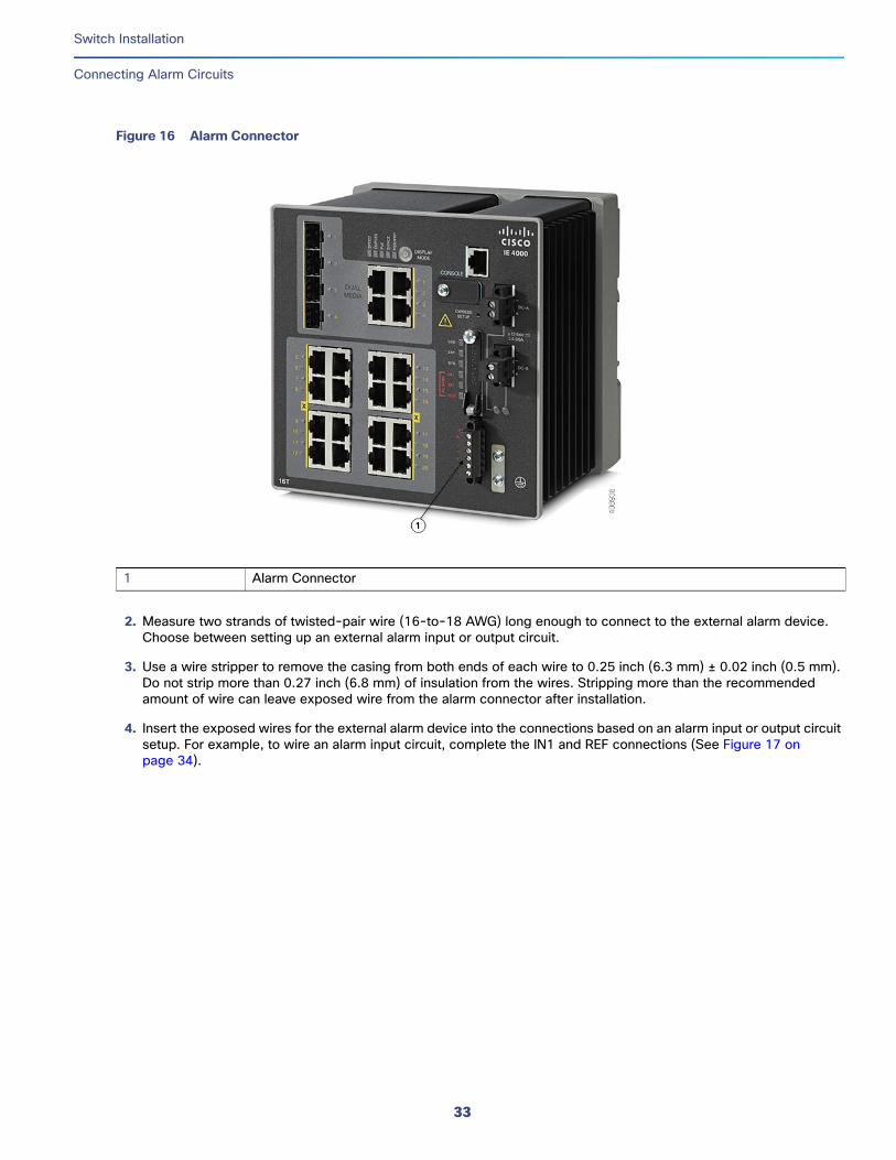
1. Remove the captive screws that hold the alarm connector on the switch, and remove the connector from the switch chassis. See Figure 16 on page 33.
Label Connection
NO Alarm Output Normally Open (NO) connection
COM Alarm Output Common connection
NC Alarm Output Normally Closed (NC) connection
IN2 Alarm Input 2
REF Alarm Input Reference Ground connection
IN1 Alarm Input 1
32
Switch Installation
Connecting Alarm Circuits
Figure 16 Alarm Connector
2. Measure two strands of twisted-pair wire (16-to-18 AWG) long enough to connect to the external alarm device. Choose between setting up an external alarm input or output circuit.
3. Use a wire stripper to remove the casing from both ends of each wire to 0.25 inch (6.3 mm) ± 0.02 inch (0.5 mm). Do not strip more than 0.27 inch (6.8 mm) of insulation from the wires. Stripping more than the recommended amount of wire can leave exposed wire from the alarm connector after installation.
4. Insert the exposed wires for the external alarm device into the connections based on an alarm input or output circuit setup. For example, to wire an alarm input circuit, complete the IN1 and REF connections (See Figure 17 on page 34).
1 Alarm Connector
33
Switch Installation
Connecting Alarm Circuits
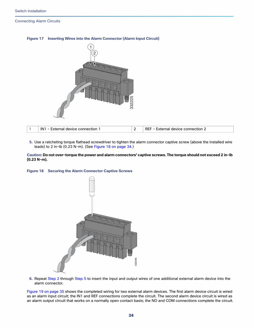
Figure 17 Inserting Wires into the Alarm Connector (Alarm Input Circuit)
5. Use a ratcheting torque flathead screwdriver to tighten the alarm connector captive screw (above the installed wire leads) to 2 in-lb (0.23 N-m). (See Figure 18 on page 34.)
Caution: Do not over-torque the power and alarm connectors’ captive screws. The torque should not exceed 2 in-lb (0.23 N-m).
Figure 18 Securing the Alarm Connector Captive Screws
6. Repeat Step 2 through Step 5 to insert the input and output wires of one additional external alarm device into the alarm connector.
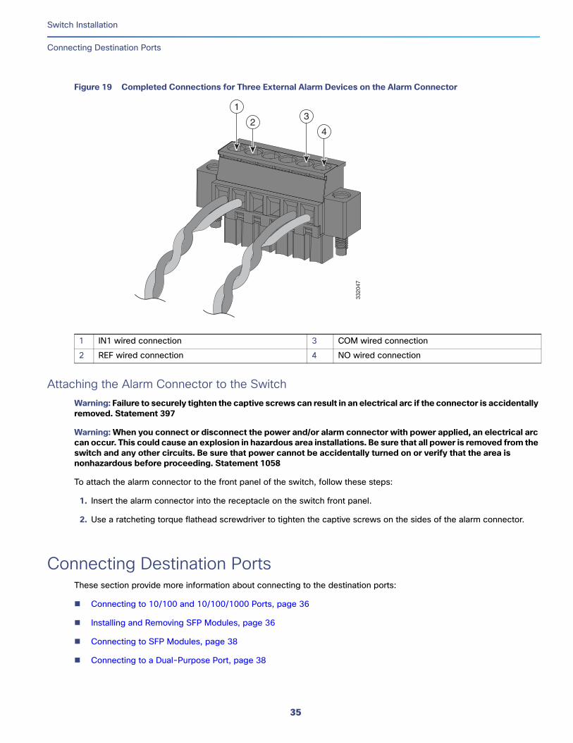
Figure 19 on page 35 shows the completed wiring for two external alarm devices. The first alarm device circuit is wired as an alarm input circuit; the IN1 and REF connections complete the circuit. The second alarm device circuit is wired as an alarm output circuit that works on a normally open contact basis; the NO and COM connections complete the circuit.
1 IN1 - External device connection 1 2 REF - External device connection 233
2225
12
3320
46
34
Switch Installation
Connecting Destination Ports
Figure 19 Completed Connections for Three External Alarm Devices on the Alarm Connector
Attaching the Alarm Connector to the SwitchWarning: Failure to securely tighten the captive screws can result in an electrical arc if the connector is accidentally removed. Statement 397
Warning: When you connect or disconnect the power and/or alarm connector with power applied, an electrical arc can occur. This could cause an explosion in hazardous area installations. Be sure that all power is removed from the switch and any other circuits. Be sure that power cannot be accidentally turned on or verify that the area is nonhazardous before proceeding. Statement 1058
To attach the alarm connector to the front panel of the switch, follow these steps:
1. Insert the alarm connector into the receptacle on the switch front panel.
2. Use a ratcheting torque flathead screwdriver to tighten the captive screws on the sides of the alarm connector.
Connecting Destination PortsThese section provide more information about connecting to the destination ports:
Connecting to 10/100 and 10/100/1000 Ports, page 36
Installing and Removing SFP Modules, page 36
Connecting to SFP Modules, page 38
Connecting to a Dual-Purpose Port, page 38
1 IN1 wired connection 3 COM wired connection
2 REF wired connection 4 NO wired connection33
2047
1
23
4
35
Switch Installation
Connecting Destination Ports
Connecting to 10/100 and 10/100/1000 PortsThe switch 10/100/1000 ports automatically configure themselves to operate at the speed of attached devices. If the attached ports do not support autonegotiation, you can explicitly set the speed and duplex parameters. Connecting devices that do not autonegotiate or that have their speed and duplex parameters manually set can reduce performance or result in no linkage.
Warning: Do not connect or disconnect cables to the ports while power is applied to the switch or any device on the network because an electrical arc can occur. This could cause an explosion in hazardous location installations. Be sure that power is removed from the switch and cannot be accidentally be turned on, or verify that the area is nonhazardous before proceeding. Statement 1070
To maximize performance, choose one of these methods for configuring the Ethernet ports:
Let the ports autonegotiate both speed and duplex.
Set the port speed and duplex parameters on both ends of the connection.
The models that support PoE provide up to four ports of either PoE (15.4 W per port; IEEE 802.3af) or PoE+ (30 W per port; IEEE 802.3at), depending on the power source used.
Caution: To prevent electrostatic-discharge (ESD) damage, follow your normal board and component handling procedures.
To connect to 10BASE-T, 100BASE-TX or 1000BASE-T devices, follow these steps:
1. When connecting to workstations, servers, routers, and Cisco IP phones, connect a straight-through cable to an RJ-45 connector on the front panel.
When connecting to 1000BASE-T-compatible devices, use a twisted four-pair, Category 5 or higher cable.
The auto-MDIX feature is enabled by default. For configuration information for this feature, see the Cisco IE 4000 Switch Software Configuration Guide .
2. Connect the other end of the cable to an RJ-45 connector on the other device. The port LED turns on when both the switch and the connected device have established a link.
The port LED is amber while Spanning Tree Protocol (STP) discovers the topology and searches for loops. This can take up to 30 seconds, and then the port LED turns green. If the port LED does not turn on:
The device at the other end might not be turned on.
There might be a cable problem or a problem with the adapter installed in the attached device. See Troubleshooting, page 53 for solutions to cabling problems.
3. Reconfigure and reboot the connected device if necessary.
4. Repeat Steps 1 through 3 to connect each device.
Installing and Removing SFP ModulesThese sections describe how to install and remove SFP modules. SFP modules are inserted into SFP module slots on the front of the switch. These field-replaceable modules provide the uplink optical interfaces, send (TX) and receive (RX).
You can use any combination of rugged SFP modules. See the release notes on Cisco.com for the list of supported modules. Each SFP module must be of the same type as the SFP module on the other end of the cable, and the cable must not exceed the stipulated cable length for reliable communications.
Caution: When you use commercial SFP modules such as CWDM and 1000BX-U/D, reduce the maximum operating temperature by 59°F (15°C). The minimum operating temperature is 32°F (0°C).
36
Switch Installation
Connecting Destination Ports
For detailed instructions on installing, removing, and cabling the SFP module, see your SFP module documentation.
Warning: Do not insert and remove SFP modules while power is on; an electrical arc can occur. This could cause an explosion in hazardous location installations. Be sure that power is removed or the area is nonhazardous before proceeding. Statement 1087
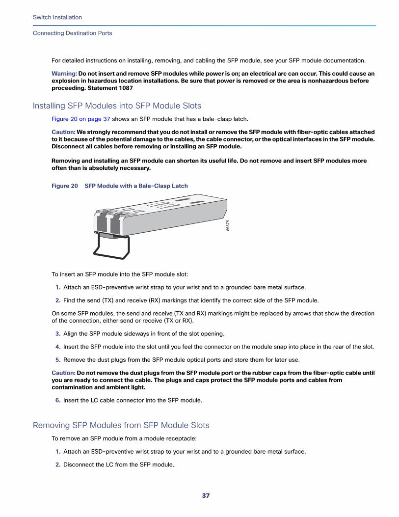
Installing SFP Modules into SFP Module SlotsFigure 20 on page 37 shows an SFP module that has a bale-clasp latch.
Caution: We strongly recommend that you do not install or remove the SFP module with fiber-optic cables attached to it because of the potential damage to the cables, the cable connector, or the optical interfaces in the SFP module. Disconnect all cables before removing or installing an SFP module.
Removing and installing an SFP module can shorten its useful life. Do not remove and insert SFP modules more often than is absolutely necessary.
Figure 20 SFP Module with a Bale-Clasp Latch
To insert an SFP module into the SFP module slot:
1. Attach an ESD-preventive wrist strap to your wrist and to a grounded bare metal surface.
2. Find the send (TX) and receive (RX) markings that identify the correct side of the SFP module.
On some SFP modules, the send and receive (TX and RX) markings might be replaced by arrows that show the direction of the connection, either send or receive (TX or RX).
3. Align the SFP module sideways in front of the slot opening.
4. Insert the SFP module into the slot until you feel the connector on the module snap into place in the rear of the slot.
5. Remove the dust plugs from the SFP module optical ports and store them for later use.
Caution: Do not remove the dust plugs from the SFP module port or the rubber caps from the fiber-optic cable until you are ready to connect the cable. The plugs and caps protect the SFP module ports and cables from contamination and ambient light.
6. Insert the LC cable connector into the SFP module.
Removing SFP Modules from SFP Module SlotsTo remove an SFP module from a module receptacle:
1. Attach an ESD-preventive wrist strap to your wrist and to a grounded bare metal surface.
2. Disconnect the LC from the SFP module.
8657
5
37
Switch Installation
Connecting Destination Ports
3. Insert a dust plug into the optical ports of the SFP module to keep the optical interfaces clean.
4. Unlock and remove the SFP module.
If the module has a bale-clasp latch, pull the bale out and down to eject the module. If the bale-clasp latch is obstructed and you cannot use your index finger to open it, use a small, flat-blade screwdriver or other long, narrow instrument to open the bale-clasp latch.
5. Grasp the SFP module between your thumb and index finger, and carefully remove it from the module slot.
6. Place the removed SFP module in an antistatic bag or other protective environment.
Connecting to SFP ModulesThis section describes how to connect to a fiber-optic SFP port. To connect to an RJ-45 Gigabit Ethernet port instead of a fiber-optic port, see Connecting to a Dual-Purpose Port, page 38. For instructions on how to install or remove an SFP module, see Installing and Removing SFP Modules, page 36.
Warning: Class 1 laser product. Statement 1008
Warning: Do not connect or disconnect cables to the ports while power is applied to the switch or any device on the network because an electrical arc can occur. This could cause an explosion in hazardous location installations. Be sure that power is removed from the switch and cannot be accidentally be turned on, or verify that the area is nonhazardous before proceeding. Statement 1070
Caution: Do not remove the rubber plugs from the SFP module port or the rubber caps from the fiber-optic cable until you are ready to connect the cable. The plugs and caps protect the SFP module ports and cables from contamination and ambient light.
Before connecting to the SFP module, be sure that you understand the port and cabling guidelines in the Preparing for Installation, page 13.
To connect a fiber-optic cable to an SFP module, follow these steps:
1. Remove the rubber plugs from the module port and fiber-optic cable, and store them for future use.
2. Insert one end of the fiber-optic cable into the SFP module port.
3. Insert the other cable end into a fiber-optic receptacle on a target device.
4. Observe the port status LED:
— The LED turns green when the switch and the target device have an established link.
— The LED turns amber while the STP discovers the network topology and searches for loops. This process takes about 30 seconds, and then the port LED turns green.
— If the LED is off, the target device might not be turned on, there might be a cable problem, or there might be a problem with the adapter installed in the target device. See Troubleshooting, page 53 for solutions to cabling problems.
5. If necessary, reconfigure and restart the switch or the target device.
Connecting to a Dual-Purpose PortThe dual-purpose port is a single port with two interfaces, one for an RJ-45 cable and another for an SFP module. Only one interface can be active at a time. If both interfaces are connected, the SFP module has priority.
Warning: Class 1 laser product. Statement 1008
38
Switch Installation
Verifying Switch Operation
Caution: Do not remove the rubber plugs from the SFP module port or the rubber caps from the fiber-optic cable until you are ready to connect the cable. The plugs and caps protect the SFP module ports and cables from contamination and ambient light.
Before connecting to the SFP module, be sure that you understand the port and cabling stipulations in the Preparing for Installation, page 13.
To connect to a dual-purpose port, follow these steps:
1. Connect an RJ-45 connector to the 10/100/1000 port, or install an SFP module into the SFP module slot, and connect a cable to the SFP module port.
For more information about RJ-45 connections, SFP modules, and optical connections, see Connecting to 10/100 and 10/100/1000 Ports, page 36, Installing and Removing SFP Modules, page 36, and Connecting to SFP Modules, page 38.
2. Connect the other end of the cable to the other device.
By default, the switch detects whether an RJ-45 connector or SFP module is connected to a dual-purpose port and configures the port accordingly. You can change this setting and configure the port to recognize only an RJ-45 connector or only an SFP module by using the media type interface configuration command. For more information, see the Cisco IE 4000 Switch Command Reference.
Verifying Switch OperationBefore installing the switch in its final location, power on the switch, and verify that the switch powers up in boot fast style. The boot fast sequence allows the switch to boot up in less than 60 seconds.
Where to Go NextIf the default configuration is satisfactory, the switch does not need further configuration. You can use any of these management options to change the default configuration:
Start Device Manager, which is in the switch memory, to manage individual and standalone switches. This is an easy-to-use web interface that offers quick configuration and monitoring. You can access Device Manager from anywhere in your network through a web browser. For more information, see the Software Configuration Guide and the Device Manager online help.
Start the Cisco Network Assistant application, which is described in the Getting Started with Cisco Network Assistant guide. Using the GUI, you can configure and monitor a switch cluster or an individual switch.
Use the CLI to configure the switch as an individual switch from the console. See the Command Reference on Cisco.com for information about using the CLI.
Start an SNMP application such as the CiscoView application.
Start the Common Industrial Protocol (CIP) management tool. You can manage an entire industrial automation system with the CIP-based tools.
39

Switch Installation
Where to Go Next
40
Running Express SetupWhen you first set up the switch, you should use Express Setup to enter the initial IP information. This process enables the switch to connect to local routers and the Internet. You can then access the switch through the IP address for additional configuration.
Required EquipmentYou need this equipment to set up the switch:
Computer with Windows 2000/Vista/2003/XP/Window7/Mac.
A Web browser (IE or Firefox) with JavaScript enabled.
A straight-through or crossover Category 5 Ethernet cable to connect your computer to the switch port.
Note: Do not use the RS232 serial console port for express setup.
A small paper clip to reach to button.
Note: Before running Express Setup, disable any pop-up blockers or proxy settings on your browser and any wireless client running on your computer.
Express Setup ProcedureTo run Express Setup:
1. Make sure that nothing is connected to the switch.
2. Ensure theIE4000 is in default factory mode.
Skip to next step if freshly out of the box.
a. If not freshly out of the package, use a paper clip to reset the switch for 10 seconds until the SYS LED light turns red, then release the paper clip.
Switch will automatically reboot once the SYS led goes red.
3. Ensure no data port is connected to the switch.
Note: During Express Setup, the switch acts as a DHCP server.
— You can add a serial console cable to monitor the booting sequence. Do not hit [return key] on console screen.
— Ensure the computer connected to switch is configured with DHCP.
4. Web Browser: disable pop-up blockers and proxy settings.
5. Connect power to the switch.
See the wiring instructions in Grounding the Switch, page 19 and Wiring the DC Power Source, page 23.
41
Cisco Systems, Inc. www.cisco.com
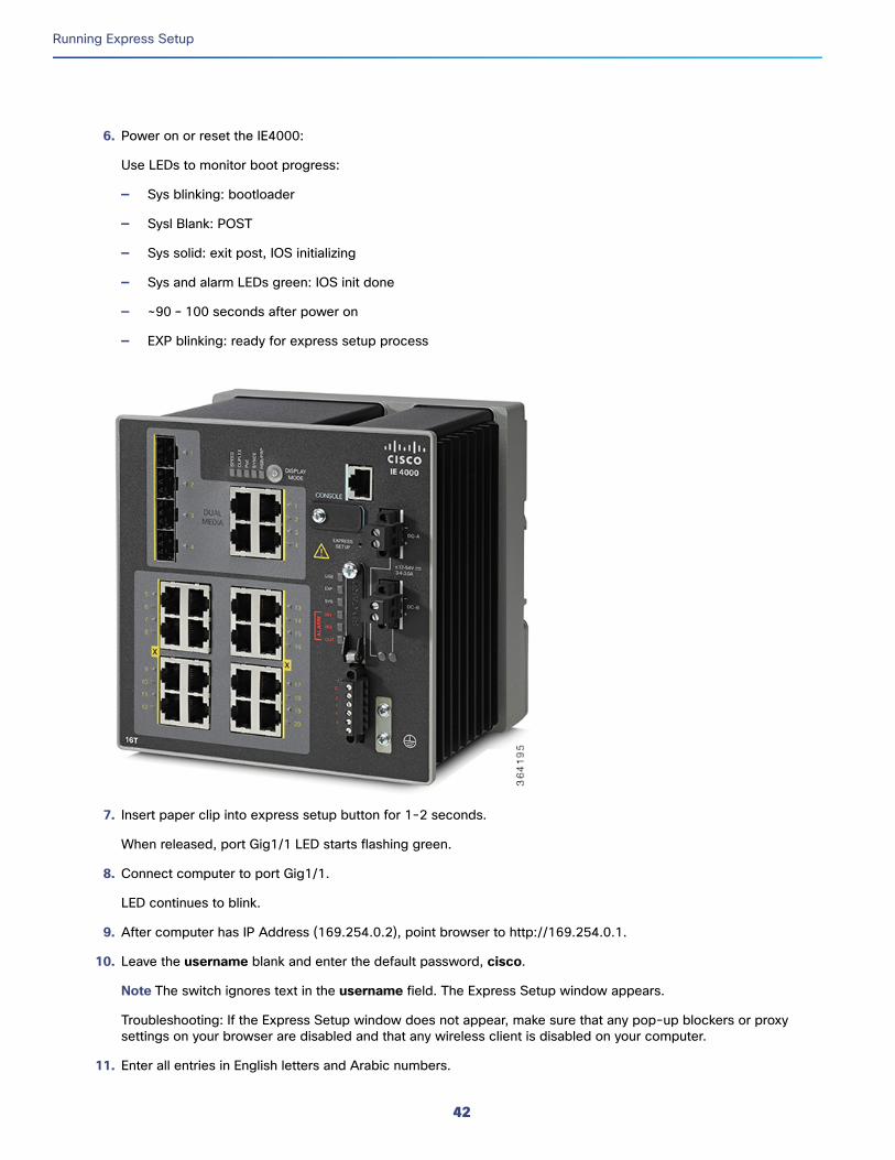
Running Express Setup
6. Power on or reset the IE4000:
Use LEDs to monitor boot progress:
— Sys blinking: bootloader
— Sysl Blank: POST
— Sys solid: exit post, IOS initializing
— Sys and alarm LEDs green: IOS init done
— ~90 – 100 seconds after power on
— EXP blinking: ready for express setup process
7. Insert paper clip into express setup button for 1-2 seconds.
When released, port Gig1/1 LED starts flashing green.
8. Connect computer to port Gig1/1.
LED continues to blink.
9. After computer has IP Address (169.254.0.2), point browser to http://169.254.0.1.
10. Leave the username blank and enter the default password, cisco.
Note The switch ignores text in the username field. The Express Setup window appears.
Troubleshooting: If the Express Setup window does not appear, make sure that any pop-up blockers or proxy settings on your browser are disabled and that any wireless client is disabled on your computer.
11. Enter all entries in English letters and Arabic numbers.
42
Running Express Setup
In the Network Settings (Required for Static IP):
— IP Address: Enter a valid IP address for the switch.
You can later use the IP address to access the switch through Device Manager.
— Switch Username and Password: Enter a password. The password can be from 1 to 25 alphanumeric characters, can start with a number, is case sensitive, allows embedded spaces, but does not allow spaces at the beginning or end. In the Confirm Password field, enter the password again.
Note You must change the password from the default password, cisco.
— Default Gateway: Enter the IP address of the router.
12. Enter the Control Industrial Protocol (CIP) VLAN settings (optional):
— CIP VLAN: Enter the VLAN on which CIP will be enabled. The CIP VLAN can be the same as the management VLAN, or you can isolate CIP traffic on another VLAN that is already configured on the switch. The default CIP VLAN is VLAN 1. Only one VLAN on a switch can have CIP enabled.
— IP Address: Enter the IP address for the CIP VLAN. If the CIP VLAN is different from the management VLAN, you must specify an IP address for the CIP VLAN. Make sure that the IP address that you assign to the switch is not being used by another device in your network.
— Subnet Mask: Select a mask from the drop-down list.
For more information about the CIP VLAN settings, click Help on the tool-bar.
13. Optional Settings
You can enter the optional information now, or enter it later by using Device Manager. For more information about the Express Setup fields, see the on-line help for the Express Setup window.
Click Submit to save your changes and to complete the initial setup.
For more information about the optional settings, click Help on the tool-bar.
14. After you click Submit, these events occur:
a. The switch is configured and exits Express Setup mode.
b. The browser displays a warning message and tries to connect with the earlier switch IP address.
c. Typically, connectivity between the computer and the switch is lost because the configured switch IP address is in a different subnet from the IP address on the computer.
15. Turn off DC power at the source, disconnect all cables to the switch, and install the switch in your network. See Management Options, page 11 for information about configuring and managing the switch.
16. If you changed the static IP address on your computer in Step 1, change it to the previously configured static IP address.
17. You can now manage the switch by using the Cisco Network Assistant, Device Manager, or both. See Management Options, page 11 for information about configuring and managing the switch.
You can display Device Manager by following these steps:
a. Start a web browser on your computer.
b. Enter the switch IP address, username, and password in the web browser, and press Enter. The Device Manager page appears.
43
Running Express Setup
Troubleshooting:
If the Device Manager page does not appear:
— Confirm that the port LED for the switch port connected to your network is green.
— Confirm that the computer that you are using to access the switch has network connectivity by connecting it to a well known web server in your network. If there is no network connection, troubleshoot the network settings on the computer.
— Make sure that the switch IP address in the browser is correct.
— If the switch IP address in the browser is correct, the switch port LED is green, and the computer has network connectivity, continue troubleshooting by reconnecting the computer to the switch. Configure a static IP address on the computer that is in the same subnet as the switch IP address.
— When the LED on the switch port connected to the computer is green, reenter the switch IP address in a web browser to display the Device Manager. When Device Manager appears, you can continue with the switch configuration.
44
Configuring the Switch with the CLI-Based Setup Program
This appendix provides a command-line interface (CLI)-based setup procedure for a switch.
Before connecting the switch to a power source, review the safety warnings in Warnings, page 13
For installation procedures, see Switch Installation, page 13
Accessing the CLI Through the Console PortYou can enter Cisco IOS commands and parameters through the CLI. Use one of these options to access the CLI:
RJ-45 Console Port, page 46
USB Mini-Type B Console Port, page 47
Removing the USB Mini-Type B Console Port CoverTo remove the cover from the USB mini-type B console port:
1. Use a Phillips screwdriver to loosen the captive screw on the USB mini-type B console port cover. See Figure 21 on page 46. Remove the screw and take off the cover.
45
Cisco Systems, Inc. www.cisco.com
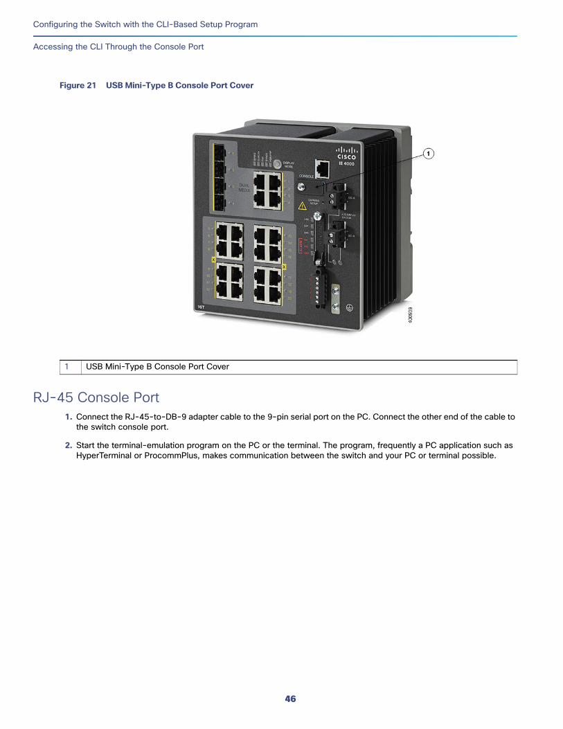
Configuring the Switch with the CLI-Based Setup Program
Accessing the CLI Through the Console Port
Figure 21 USB Mini-Type B Console Port Cover
RJ-45 Console Port 1. Connect the RJ-45-to-DB-9 adapter cable to the 9-pin serial port on the PC. Connect the other end of the cable to
the switch console port.
2. Start the terminal-emulation program on the PC or the terminal. The program, frequently a PC application such as HyperTerminal or ProcommPlus, makes communication between the switch and your PC or terminal possible.
1 USB Mini-Type B Console Port Cover
46
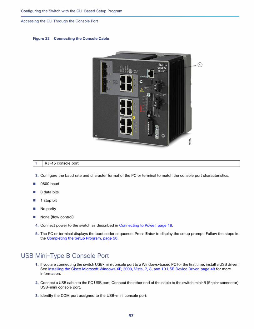
Configuring the Switch with the CLI-Based Setup Program
Accessing the CLI Through the Console Port
Figure 22 Connecting the Console Cable
3. Configure the baud rate and character format of the PC or terminal to match the console port characteristics:
9600 baud
8 data bits
1 stop bit
No parity
None (flow control)
4. Connect power to the switch as described in Connecting to Power, page 18.
5. The PC or terminal displays the bootloader sequence. Press Enter to display the setup prompt. Follow the steps in the Completing the Setup Program, page 50.
USB Mini-Type B Console Port1. If you are connecting the switch USB-mini console port to a Windows-based PC for the first time, install a USB driver.
See Installing the Cisco Microsoft Windows XP, 2000, Vista, 7, 8, and 10 USB Device Driver, page 48 for more information.
2. Connect a USB cable to the PC USB port. Connect the other end of the cable to the switch mini-B (5-pin-connector) USB-mini console port.
3. Identify the COM port assigned to the USB-mini console port:
1 RJ-45 console port
47
Configuring the Switch with the CLI-Based Setup Program
Accessing the CLI Through the Console Port
c. Choose Start > Control Panel > Systems.
d. Click the Hardware tab and choose Device Manager. Expand the Ports section. The assigned COM port appears in parenthesis at the end of the line with this entry: Cisco USB System Management Console.
4. Start the terminal-emulation program on the PC or the terminal. The program, frequently a PC application such as HyperTerminal or ProcommPlus, makes communication possible between the switch and your PC or terminal.
5. Configure the COM port.
6. Configure the baud rate and character format of the PC or terminal to match the console port characteristics:
9600 baud
8 data bits
1 stop bit
No parity
None (flow control)
7. Connect power to the switch as described in Connecting to Power, page 18.
8. The PC or terminal displays the bootloader sequence. Press Enter to display the setup prompt. Follow the steps in the Completing the Setup Program, page 50.
Installing the Cisco Microsoft Windows XP, 2000, Vista, 7, 8, and 10 USB Device Driver
A USB device driver must be installed the first time a Microsoft Windows-based PC is connected to the USB console port on the switch. Use this procedure to install the USB driver on Windows XP, Windows 2000, Windows Vista, Windows 7, Windows 8, and Windows 10.
1. Obtain the file Cisco_usbconsole_driver_3_1.zip from the Cisco.com website https://software.cisco.com/download/release.html?mdfid=282979369&softwareid=282855122&release=3.1
The file details are as follows:
— Description: Cisco_usbconsole_driver_3_1.zip
— Release: 3.1
— Release Date: 27/Nov/2014
— File Name: Cisco_usbconsole_driver_3_1.zip
— Size: 14.35 MB (15045453 bytes)
— MD5 Checksum: eff2e955edcdc70209e6f9c8f6bd59cd
2. Unzip the file and install the corresponding exe file.
3. Navigate to the Device Manager window by performing a search in WIndows for Device Manager and opening it.
4. Connect the USB cable from the Windows PC to the Cisco switch.
5. From the Device Manager page, expand Ports (COM & LPT). Select USB Serial Port. Right-click and select Update Driver Software ...
48
Configuring the Switch with the CLI-Based Setup Program
Entering the Initial Configuration Information
6. In the Update Driver Software window, select Browse my computer for driver software. Then choose Let me pick from a list of device drivers on my computer and click Next.
7. Enable Show compatible hardware and choose Cisco Serial as the model. Click Next.
After the update is completed, Windows displays Windows has successfully updated your driver software.
8. Click Close.
Uninstalling the Cisco Microsoft Windows XP, 2000, Vista, 7, 8, and 10 USB Driver
Note: Disconnect the switch console terminal before uninstalling the driver.
1. Run setup.exe for Windows 32-bit or setup(x64).exe for Windows-64bit.
2. Click Next.
3. When the InstallShield Wizard for Cisco Virtual Com appears, click Next.
4. When the Program Maintenance window appears, select the Remove radio button.
5. Click Next.
6. When the Remove the Program window appears, click Remove.
If a User Account Control warning appears, click Allow - I trust this program to proceed.
7. When the InstallShield Wizard Completed window appears, click Finish.
Entering the Initial Configuration InformationTo set up the switch, you need to complete the setup program, which runs automatically after the switch is powered on. You must assign an IP address and other configuration information necessary for the switch to communicate with the local routers and the Internet. This information is also required if you plan to use Device Manager or Cisco Network Assistant to configure and manage the switch.
IP SettingsYou need this information from your network administrator before you complete the setup program:
Switch IP address
Subnet mask (IP netmask)
Default gateway (router)
Enable secret password
Enable password
Telnet password
49
Configuring the Switch with the CLI-Based Setup Program
Entering the Initial Configuration Information
Completing the Setup ProgramTo complete the setup program and to create an initial configuration for the switch:
1. Enter Yes at these two prompts:
Would you like to enter the initial configuration dialog? [yes/no]: yes
At any point you may enter a question mark '?' for help.Use ctrl-c to abort configuration dialog at any prompt.Default settings are in square brackets '[]'.
Basic management setup configures only enough connectivityfor management of the system, extended setup will ask youto configure each interface on the system.
Would you like to enter basic management setup? [yes/no]: yes
2. Enter a hostname for the switch, and press Return.
On a command switch, the hostname is limited to 28 characters; on a member switch, it is limited to 31 characters. Do not use -n, where n is a number, as the last character in a hostname for any switch.
Enter host name [Switch]: host_name
3. Enter an enable secret password, and press Return.
The password can be from 1 to 25 alphanumeric characters, can start with a number, is case sensitive, allows spaces, but ignores leading spaces. The secret password is encrypted, and the enable password is in plain text.
Enter enable secret: secret_password
4. Enter an enable password, and press Return.
Enter enable password: enable_password
5. Enter a virtual terminal (Telnet) password, and press Return.
The password can be from 1 to 25 alphanumeric characters, is case sensitive, allows spaces, but ignores leading spaces.
Enter virtual terminal password: terminal-password
6. (Optional) Configure Simple Network Management Protocol (SNMP) by responding to the prompts. You can also configure SNMP later through the CLI, Device Manager, or the Cisco Network Assistant application. To configure SNMP later, enter no.
Configure SNMP Network Management? [no]: no
7. Enter the interface name (physical interface or VLAN name) of the interface that connects to the management network, and press Return. For this release, always use vlan1 as that interface.
Enter interface name used to connect to themanagement network from the above interface summary: vlan1
8. Configure the interface by entering the switch IP address and subnet mask and pressing Return. The IP address and subnet masks shown here are examples.
Configuring interface vlan1:Configure IP on this interface? [yes]: yes IP address for this interface: 10.4.120.106Subnet mask for this interface [255.0.0.0]: 255.0.0.0
50
Configuring the Switch with the CLI-Based Setup Program
Entering the Initial Configuration Information
9. Enter Y to configure the switch as the cluster command switch. Enter N to configure it as a member switch or as a standalone switch.
If you enter N, the switch appears as a candidate switch in the Cisco Network Assistant GUI. You can configure the switch as a command switch later through the CLI, Device Manager, or the Cisco Network Assistant application. To configure it later, enter no.
Would you like to enable as a cluster command switch? [yes/no]: no
You have now completed the initial configuration of the switch, and the switch displays its initial configuration script:
The following configuration command script was created:
hostname Switchenable secret 5 $1$ZQRe$DPulYXyQLm77v/a4Bmu6Y.enable password ciscoline vty 0 15password ciscono snmp-server!!interface Vlan1no shutdownip address 10.4.120.106 255.0.0.0!interface FastEthernet1/1!interface FastEthernet1/2!interface FastEthernet1/3!...(output abbreviated)!interface GigabitEthernet1/1!interface GigabitEthernet1/2!end
10. These choices appear:
[0] Go to the IOS command prompt without saving this config.
[1] Return back to the setup without saving this config.
[2] Save this configuration to nvram and exit.
If you want to save the configuration and use it the next time the switch reboots, save it in NVRAM by selecting option 2.
Enter your selection [2]:2
Make your selection, and press Return.
After you complete the setup program, the switch can run the default configuration that you created. If you want to change this configuration or want to perform other management tasks, use one of these tools:
Command-line interface (CLI)
Cisco Network Assistant (for one or more switches)
51

Configuring the Switch with the CLI-Based Setup Program
Entering the Initial Configuration Information
To use the CLI, enter commands at the Switch> prompt through the console port by using a terminal emulation program or through the network by using Telnet. For configuration information, see the switch Cisco IE 4000 Switch Software Configuration Guide.
To use the Cisco Network Assistant, see the Getting Started with Cisco Network Assistant guide on Cisco.com.
52
TroubleshootingThis chapter provides these topics for troubleshooting problems:
Diagnosing Problems, page 53
How to Recover Passwords, page 56
Finding the Switch Serial Number, page 56
Diagnosing ProblemsThe switch LEDs provide troubleshooting information about the switch. They show boot fast failures, port-connectivity problems, and overall switch performance. You can also get statistics from Device Manager, the CLI, or an SNMP workstation. See the Cisco IE 4000 Switch Software Configuration Guide, or the documentation that came with your SNMP application for details.
Switch Boot FastSee Verifying Switch Operation, page 39 for information on boot fast.
Note: Boot fast failures are usually fatal. Contact your Cisco TAC representative if your switch does not successfully complete boot fast.
Note: You can disable the boot fast and run POST by using the Cisco IOS CLI, see the Cisco IE 4000 Switch Software Configuration Guide for more information.
Switch LEDsLook at the port LEDs information when troubleshooting the switch. See LEDs, page 6 for a description of the LED colors and their meanings.
Switch Connections
Bad or Damaged CableAlways examine the cable for marginal damage or failure. A cable might be just good enough to connect at the physical layer, but it could corrupt packets as a result of subtle damage to the wiring or connectors. You can identify this problem because the port has many packet errors or it constantly flaps (loses and regains link).
Exchange the copper or fiber-optic cable with a known good cable.
Look for broken or missing pins on cable connectors.
Rule out any bad patch panel connections or media convertors between the source and the destination. If possible, bypass the patch panel, or eliminate media convertors (fiber-optic-to-copper).
Try the cable in another port to see if the problem follows the cable.
53
Cisco Systems, Inc. www.cisco.com
Troubleshooting
Diagnosing Problems
Ethernet and Fiber-Optic CablesMake sure that you have the correct cable:
For Ethernet, use Category 3 copper cable for 10 Mb/s UTP connections. Use either Category 5, Category 5e, or Category 6 UTP for 10/100, 10/100/1000 Mb/s, and PoE connections.
Verify that you have the correct fiber-optic cable for the distance and port type. Make sure that the connected device ports match and use the same type encoding, optical frequency, and fiber type.
Determine if a copper crossover cable was used when a straight-through was required or the reverse. Enable auto-MDIX on the switch, or replace the cable.
Link StatusVerify that both sides have a link. A broken wire or a shutdown port can cause one side to show a link even though the other side does not have a link.
A port LED that is on does not guarantee that the cable is functional. It might have encountered physical stress, causing it to function at a marginal level. If the port LED does not turn on:
Connect the cable from the switch to a known good device.
Make sure that both ends of the cable are connected to the correct ports.
Verify that both devices have power.
Verify that you are using the correct cable type. See Cables and Adapters, page 65 for information.
Look for loose connections. Sometimes a cable appears to be seated but is not. Disconnect the cable, and then reconnect it.
10/100/1000 Port ConnectionsIf a port appears to malfunction:
Verify the status of all ports by checking the LEDs. For more information, see Switch LEDs, page 53.
Use the show interfaces privileged EXEC command to see if the port is error-disabled, disabled, or shut down. Reenable the port if necessary.
Verify the cable type. See Cable and Connectors, page 63.
SFP Module Use only Cisco SFP modules. Each Cisco module has an internal serial EEPROM that is encoded with security information. This encoding verifies that the module meets the requirements for the switch.
Inspect the SFP module. Exchange the suspect module with a known good module.
Verify that the module is supported on this platform. (The switch release notes on Cisco.com list the SFP modules that the switch supports.)
Use the show interfaces privileged EXEC command to see if the port or module is error-disabled, disabled, or shutdown. Reenable the port if needed.
Make sure that all fiber-optic connections are clean and securely connected.
54
Troubleshooting
Diagnosing Problems
Interface SettingsVerify that the interface is not disabled or powered off. If an interface is manually shut down on either side of the link, it does not come up until you reenable the interface. Use the show interfaces privileged EXEC command to see if the interface is error-disabled, disabled, or shut down on either side of the connection. If needed, reenable the interface.
Ping End DevicePing from the directly connected switch first, and then work your way back port by port, interface by interface, trunk by trunk, until you find the source of the connectivity issue. Make sure that each switch can identify the end device MAC address in its Content-Addressable Memory (CAM) table.
Spanning Tree LoopsSTP loops can cause serious performance issues that look like port or interface problems.
A unidirectional link can cause loops. It occurs when the traffic sent by the switch is received by the neighbor, but the traffic from the neighbor is not received by the switch. A broken cable, other cabling problems, or a port issue can cause this one-way communication.
You can enable UniDirectional Link Detection (UDLD) on the switch to help identify unidirectional link problems. For information about enabling UDLD on the switch, see the “Understanding UDLD” section in the switch software configuration guide on Cisco.com.
Switch Performance
Speed, Duplex, and AutonegotiationPort statistics that show a large amount of alignment errors, frame check sequence (FCS), or late-collisions errors, might mean a speed or duplex mismatch.
A common issue occurs when duplex and speed settings are mismatched between two switches, between a switch and a router, or between the switch and a workstation or server. Mismatches can happen when manually setting the speed and duplex or from autonegotiation issues between the two devices.
To maximize switch performance and to ensure a link, follow one of these guidelines when changing the duplex or the speed settings.
Let both ports autonegotiate both speed and duplex.
Manually set the speed and duplex parameters for the interfaces on both ends of the connection.
If a remote device does not autonegotiate, use the same duplex settings on the two ports. The speed parameter adjusts itself even if the connected port does not autonegotiate.
Autonegotiation and Network Interface CardsProblems sometimes occur between the switch and third-party network interface cards (NICs). By default, the switch ports and interfaces autonegotiate. Laptops or other devices are commonly set to autonegotiate, yet sometimes issues occur.
To troubleshoot autonegotiation problems, try manually setting both sides of the connection. If this does not solve the problem, there could be a problem with the firmware or software on the NIC. You can resolve this by upgrading the NIC driver to the latest version.
55
Troubleshooting
Resetting the Switch
Cabling DistanceIf the port statistics show excessive FCS, late-collision, or alignment errors, verify that the cable distance from the switch to the connected device meets the recommended guidelines. See Cables and Adapters, page 65.
Resetting the SwitchThese are reasons why you might want to reset the switch to the factory default settings:
You installed the switch in your network and cannot connect to it because you assigned the wrong IP address.
You want to reset the password on the switch.
Note: Resetting the switch deletes the configuration and reboots the switch.
Caution: If you press the Express Setup button when you power on, the automatic boot sequence stops, and the switch enters bootloader mode.
To reset the switch:
1. Press and hold the Express Setup button (recessed behind a small hole in the faceplate) for about 10 seconds with a paper clip or similar object. The switch reboots. The system LED turns green after the switch completes rebooting.
2. Press the Express Setup button again for 3 seconds. A switch 10/100 Ethernet port blinks green.
The switch now behaves like an unconfigured switch. You can configure the switch by using the CLI setup procedure described in Configuring the Switch with the CLI-Based Setup Program, page 45
How to Recover PasswordsPassword recovery is a feature that a system administrator can enable or disable. If password recovery is disabled, the only way to recover from a lost or forgotten password is to clear the switch configuration entirely. For this procedure, see How to Recover Passwords, page 56.
The Cisco IE 4000 Switch Software Configuration Guide provides details about enabling and disabling the password recovery feature and the procedure for recovering passwords.
Finding the Switch Serial NumberIf you contact Cisco Technical Assistance, you need to know the serial number of your switch. The serial number is on the compliance label on the right-hand side of the switch. See Figure 23 on page 57. You can also use the show version privileged EXEC command to obtain the switch serial number.
56
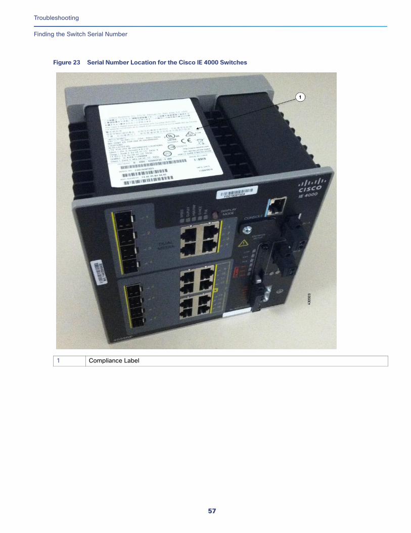
Troubleshooting
Finding the Switch Serial Number
Figure 23 Serial Number Location for the Cisco IE 4000 Switches
1 Compliance Label
57

Troubleshooting
Finding the Switch Serial Number
58

Technical SpecificationsThis appendix provides the technical specification for the Cisco IE 4000 switches.
Operating Temperature SpecificationsTable 3 on page 59 lists the operating temperatures for the Cisco IE 4000 switches in three different environments.
Note: The safety certifications apply only to ambient temperatures under 158°F (70°C). However, the Cisco IE 4000 switch can function in the substation and traffic signal installations under the environmental conditions shown in Table 3 on page 59.
Table 3 Operating Temperature for the Cisco IE 4000 Switches
Industrial Automation and Hazardous Locations
Substation Traffic Signal
Enclosure types
Sealed enclosures
For example: NEMA4, NEMA4X, NEMA12, NEMA13, IP54, and IP66.
Vented enclosures
For example: NEMA1, IP20, and IP21.
Fan or blower-equipped enclosures
For example: NEMA TS-2.
Note: The minimum airflow is 150 lfm1.
1. lfm = linear feet per minute.
59
Cisco Systems, Inc. www.cisco.com
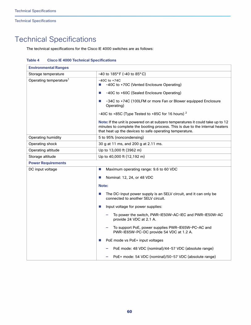
Technical Specifications
Technical Specifications
Technical SpecificationsThe technical specifications for the Cisco IE 4000 switches are as follows:
Table 4 Cisco IE 4000 Technical Specifications
Environmental Ranges
Storage temperature –40 to 185°F (–40 to 85°C)
Operating temperature1 -40C to +74C -40C to +70C (Vented Enclosure Operating)
-40C to +60C (Sealed Enclosure Operating)
-34C to +74C (100LFM or more Fan or Blower equipped Enclosure Operating)
-40C to +85C (Type Tested to +85C for 16 hours) 2
Note: If the unit is powered on at subzero temperatures it could take up to 12 minutes to complete the booting process. This is due to the internal heaters that heat up the devices to safe operating temperature.
Operating humidity 5 to 95% (noncondensing)
Operating shock 30 g at 11 ms, and 200 g at 2.11 ms.
Operating altitude Up to 13,000 ft (3962 m)
Storage altitude Up to 40,000 ft (12,192 m)
Power Requirements
DC input voltage Maximum operating range: 9.6 to 60 VDC
Nominal: 12, 24, or 48 VDC
Note:
The DC-input power supply is an SELV circuit, and it can only be connected to another SELV circuit.
Input voltage for power supplies:
— To power the switch, PWR-IE50W-AC-IEC and PWR-IE50W-AC provide 24 VDC at 2.1 A.
— To support PoE, power supplies PWR-IE65W-PC-AC and PWR-IE65W-PC-DC provide 54 VDC at 1.2 A.
PoE mode vs PoE+ input voltages
— PoE mode: 48 VDC (nominal)/44-57 VDC (absolute range)
— PoE+ mode: 54 VDC (nominal)/50-57 VDC (absolute range)
60
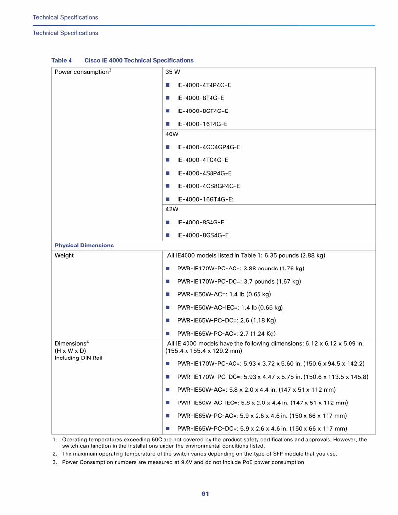
Technical Specifications
Technical Specifications
Power consumption3 35 W
IE-4000-4T4P4G-E
IE-4000-8T4G-E
IE-4000-8GT4G-E
IE-4000-16T4G-E
40W
IE-4000-4GC4GP4G-E
IE-4000-4TC4G-E
IE-4000-4S8P4G-E
IE-4000-4GS8GP4G-E
IE-4000-16GT4G-E:
42W
IE-4000-8S4G-E
IE-4000-8GS4G-E
Physical Dimensions
Weight All IE4000 models listed in Table 1: 6.35 pounds (2.88 kg)
PWR-IE170W-PC-AC=: 3.88 pounds (1.76 kg)
PWR-IE170W-PC-DC=: 3.7 pounds (1.67 kg)
PWR-IE50W-AC=: 1.4 lb (0.65 kg)
PWR-IE50W-AC-IEC=: 1.4 lb (0.65 kg)
PWR-IE65W-PC-DC=: 2.6 (1.18 Kg)
PWR-IE65W-PC-AC=: 2.7 (1.24 Kg)
Dimensions4 (H x W x D)Including DIN Rail
All IE 4000 models have the following dimensions: 6.12 x 6.12 x 5.09 in. (155.4 x 155.4 x 129.2 mm)
PWR-IE170W-PC-AC=: 5.93 x 3.72 x 5.60 in. (150.6 x 94.5 x 142.2)
PWR-IE170W-PC-DC=: 5.93 x 4.47 x 5.75 in. (150.6 x 113.5 x 145.8)
PWR-IE50W-AC=: 5.8 x 2.0 x 4.4 in. (147 x 51 x 112 mm)
PWR-IE50W-AC-IEC=: 5.8 x 2.0 x 4.4 in. (147 x 51 x 112 mm)
PWR-IE65W-PC-AC=: 5.9 x 2.6 x 4.6 in. (150 x 66 x 117 mm)
PWR-IE65W-PC-DC=: 5.9 x 2.6 x 4.6 in. (150 x 66 x 117 mm)
1. Operating temperatures exceeding 60C are not covered by the product safety certifications and approvals. However, the switch can function in the installations under the environmental conditions listed.
2. The maximum operating temperature of the switch varies depending on the type of SFP module that you use. 3. Power Consumption numbers are measured at 9.6V and do not include PoE power consumption
Table 4 Cisco IE 4000 Technical Specifications
61
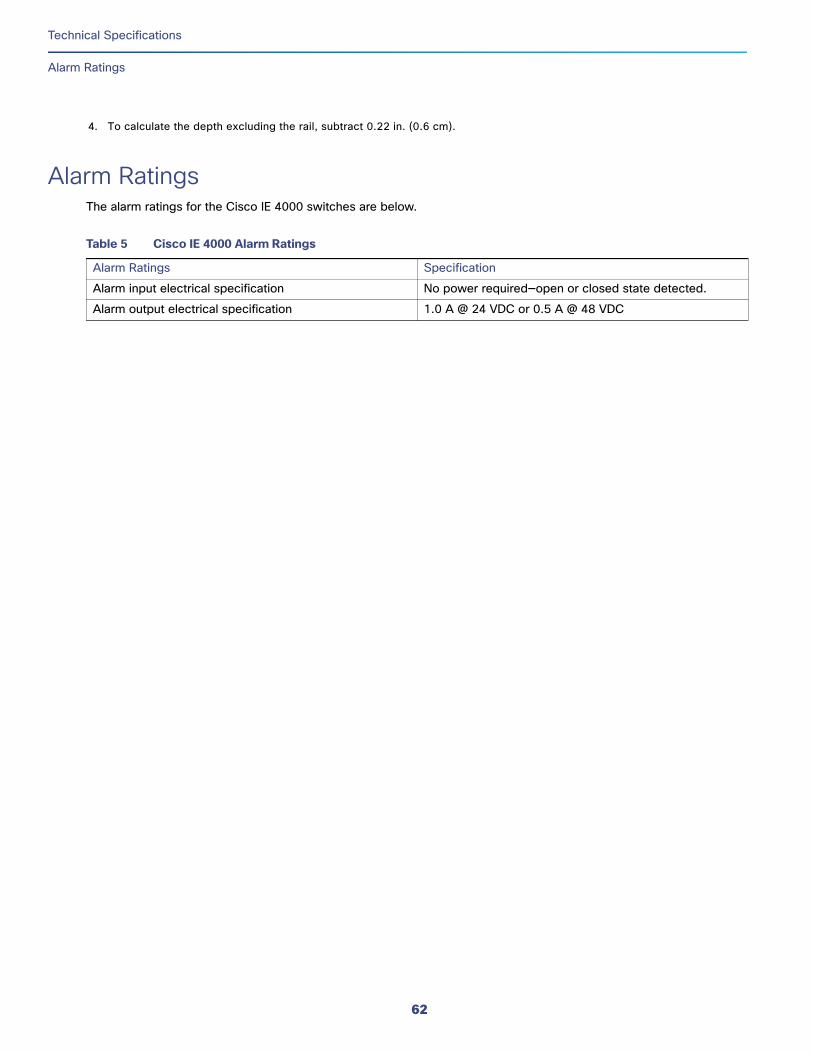
Technical Specifications
Alarm Ratings
Alarm RatingsThe alarm ratings for the Cisco IE 4000 switches are below.
4. To calculate the depth excluding the rail, subtract 0.22 in. (0.6 cm).
Table 5 Cisco IE 4000 Alarm Ratings
Alarm Ratings Specification
Alarm input electrical specification No power required—open or closed state detected.
Alarm output electrical specification 1.0 A @ 24 VDC or 0.5 A @ 48 VDC
62
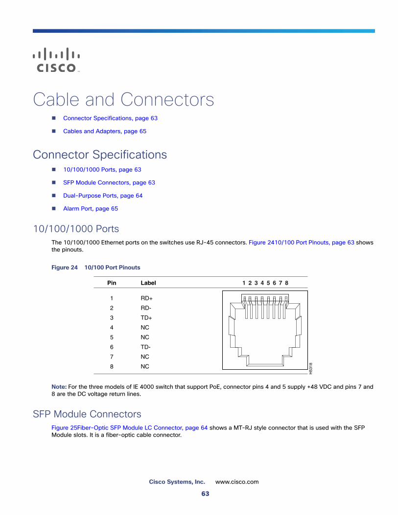
Cable and Connectors Connector Specifications, page 63
Cables and Adapters, page 65
Connector Specifications 10/100/1000 Ports, page 63
SFP Module Connectors, page 63
Dual-Purpose Ports, page 64
Alarm Port, page 65
10/100/1000 PortsThe 10/100/1000 Ethernet ports on the switches use RJ-45 connectors. Figure 2410/100 Port Pinouts, page 63 shows the pinouts.
Figure 24 10/100 Port Pinouts
Note: For the three models of IE 4000 switch that support PoE, connector pins 4 and 5 supply +48 VDC and pins 7 and 8 are the DC voltage return lines.
SFP Module ConnectorsFigure 25Fiber-Optic SFP Module LC Connector, page 64 shows a MT-RJ style connector that is used with the SFP Module slots. It is a fiber-optic cable connector.
H53
18
2 31 4 5 6 7 8Pin Label
1
2
3
4
5
6
7
8
RD+
RD-
TD+
NC
NC
TD-
NC
NC
63
Cisco Systems, Inc. www.cisco.com
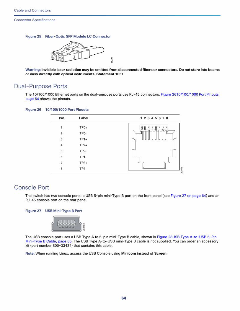
Cable and Connectors
Connector Specifications
Figure 25 Fiber-Optic SFP Module LC Connector
Warning: Invisible laser radiation may be emitted from disconnected fibers or connectors. Do not stare into beams or view directly with optical instruments. Statement 1051
Dual-Purpose PortsThe 10/100/1000 Ethernet ports on the dual-purpose ports use RJ-45 connectors. Figure 2610/100/1000 Port Pinouts, page 64 shows the pinouts.
Figure 26 10/100/1000 Port Pinouts
Console PortThe switch has two console ports: a USB 5-pin mini-Type B port on the front panel (see Figure 27 on page 64) and an RJ-45 console port on the rear panel.
Figure 27 USB Mini-Type B Port
The USB console port uses a USB Type A to 5-pin mini-Type B cable, shown in Figure 28USB Type A-to-USB 5-Pin Mini-Type B Cable, page 65. The USB Type A-to-USB mini-Type B cable is not supplied. You can order an accessory kit (part number 800-33434) that contains this cable.
Note: When running Linux, access the USB Console using Minicom instead of Screen.
5847
6
6091
5
2 31 4 5 6 7 8Pin Label
1
2
3
4
5
6
7
8
TP0+
TP0-
TP1+
TP2+
TP2-
TP1-
TP3+
TP3-
2531
63
64
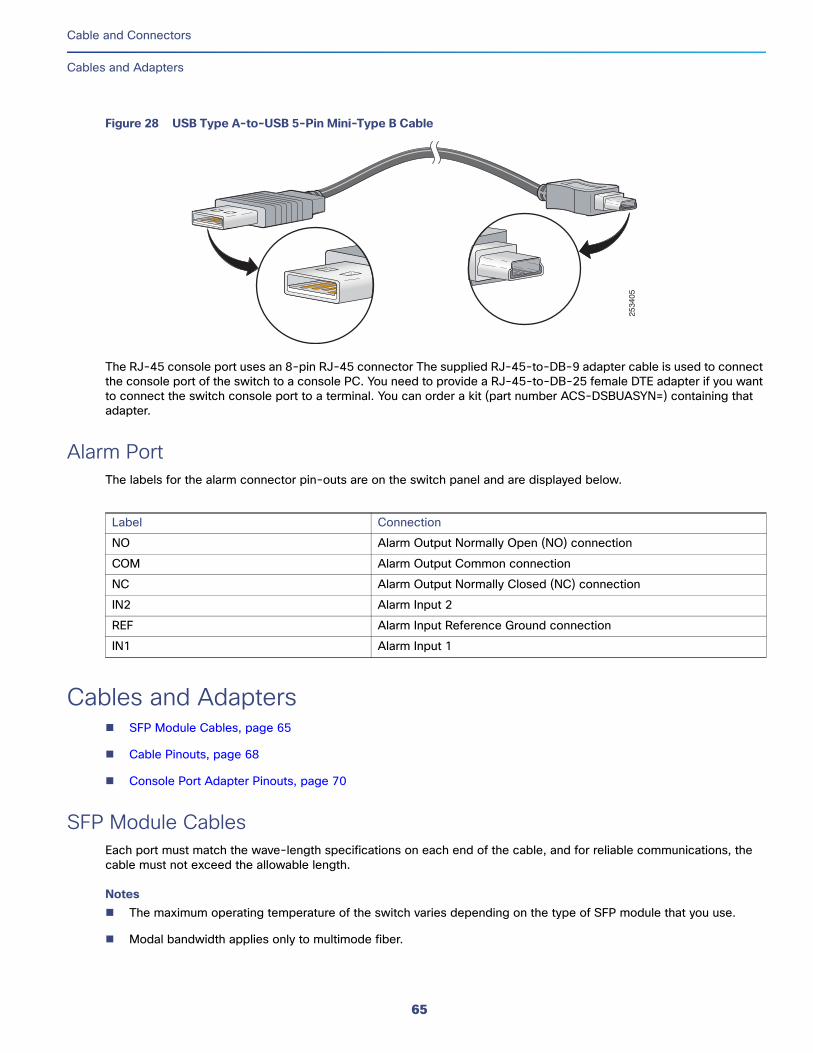
Cable and Connectors
Cables and Adapters
Figure 28 USB Type A-to-USB 5-Pin Mini-Type B Cable
The RJ-45 console port uses an 8-pin RJ-45 connector The supplied RJ-45-to-DB-9 adapter cable is used to connect the console port of the switch to a console PC. You need to provide a RJ-45-to-DB-25 female DTE adapter if you want to connect the switch console port to a terminal. You can order a kit (part number ACS-DSBUASYN=) containing that adapter.
Alarm PortThe labels for the alarm connector pin-outs are on the switch panel and are displayed below.
Cables and Adapters SFP Module Cables, page 65
Cable Pinouts, page 68
Console Port Adapter Pinouts, page 70
SFP Module Cables Each port must match the wave-length specifications on each end of the cable, and for reliable communications, the cable must not exceed the allowable length.
Notes The maximum operating temperature of the switch varies depending on the type of SFP module that you use.
Modal bandwidth applies only to multimode fiber.
2534
05
Label Connection
NO Alarm Output Normally Open (NO) connection
COM Alarm Output Common connection
NC Alarm Output Normally Closed (NC) connection
IN2 Alarm Input 2
REF Alarm Input Reference Ground connection
IN1 Alarm Input 1
65
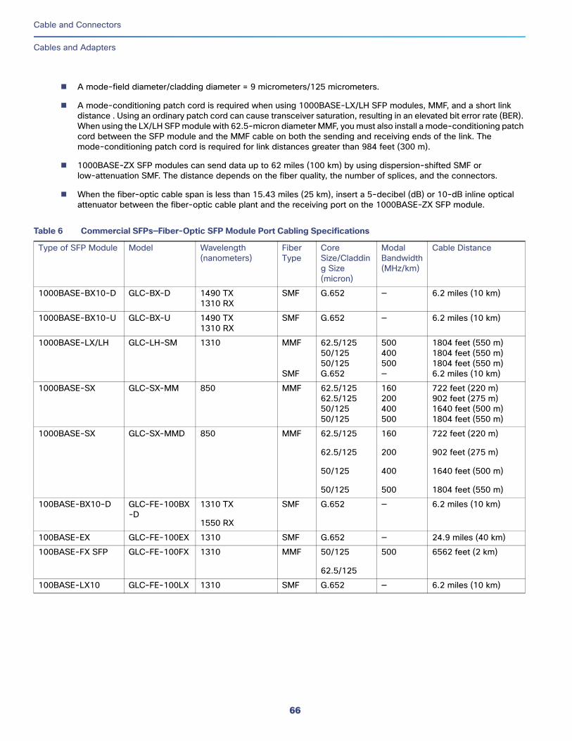
Cable and Connectors
Cables and Adapters
A mode-field diameter/cladding diameter = 9 micrometers/125 micrometers.
A mode-conditioning patch cord is required when using 1000BASE-LX/LH SFP modules, MMF, and a short link distance . Using an ordinary patch cord can cause transceiver saturation, resulting in an elevated bit error rate (BER). When using the LX/LH SFP module with 62.5-micron diameter MMF, you must also install a mode-conditioning patch cord between the SFP module and the MMF cable on both the sending and receiving ends of the link. The mode-conditioning patch cord is required for link distances greater than 984 feet (300 m).
1000BASE-ZX SFP modules can send data up to 62 miles (100 km) by using dispersion-shifted SMF or low-attenuation SMF. The distance depends on the fiber quality, the number of splices, and the connectors.
When the fiber-optic cable span is less than 15.43 miles (25 km), insert a 5-decibel (dB) or 10-dB inline optical attenuator between the fiber-optic cable plant and the receiving port on the 1000BASE-ZX SFP module.
Table 6 Commercial SFPs—Fiber-Optic SFP Module Port Cabling Specifications
Type of SFP Module Model Wavelength (nanometers)
Fiber Type
Core Size/Cladding Size (micron)
Modal Bandwidth (MHz/km)
Cable Distance
1000BASE-BX10-D GLC-BX-D 1490 TX1310 RX
SMF G.652 — 6.2 miles (10 km)
1000BASE-BX10-U GLC-BX-U 1490 TX1310 RX
SMF G.652 — 6.2 miles (10 km)
1000BASE-LX/LH GLC-LH-SM 1310 MMF
SMF
62.5/12550/12550/125G.652
500400500—
1804 feet (550 m)1804 feet (550 m)1804 feet (550 m)6.2 miles (10 km)
1000BASE-SX GLC-SX-MM 850 MMF 62.5/12562.5/12550/12550/125
160200400500
722 feet (220 m)902 feet (275 m)1640 feet (500 m)1804 feet (550 m)
1000BASE-SX GLC-SX-MMD 850 MMF 62.5/125
62.5/125
50/125
50/125
160
200
400
500
722 feet (220 m)
902 feet (275 m)
1640 feet (500 m)
1804 feet (550 m)
100BASE-BX10-D GLC-FE-100BX-D
1310 TX
1550 RX
SMF G.652 — 6.2 miles (10 km)
100BASE-EX GLC-FE-100EX 1310 SMF G.652 — 24.9 miles (40 km)
100BASE-FX SFP GLC-FE-100FX 1310 MMF 50/125
62.5/125
500 6562 feet (2 km)
100BASE-LX10 GLC-FE-100LX 1310 SMF G.652 — 6.2 miles (10 km)
66
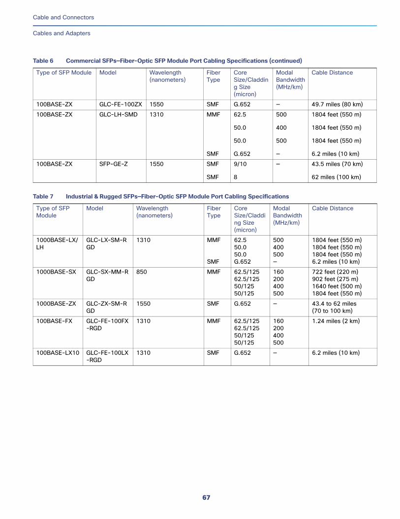
Cable and Connectors
Cables and Adapters
100BASE-ZX GLC-FE-100ZX 1550 SMF G.652 — 49.7 miles (80 km)
100BASE-ZX GLC-LH-SMD 1310 MMF
SMF
62.5
50.0
50.0
G.652
500
400
500
—
1804 feet (550 m)
1804 feet (550 m)
1804 feet (550 m)
6.2 miles (10 km)
100BASE-ZX SFP-GE-Z 1550 SMF
SMF
9/10
8
— 43.5 miles (70 km)
62 miles (100 km)
Table 7 Industrial & Rugged SFPs—Fiber-Optic SFP Module Port Cabling Specifications
Type of SFP Module
Model Wavelength (nanometers)
Fiber Type
Core Size/Cladding Size (micron)
Modal Bandwidth (MHz/km)
Cable Distance
1000BASE-LX/LH
GLC-LX-SM-RGD
1310 MMF
SMF
62.550.050.0G.652
500400500—
1804 feet (550 m)1804 feet (550 m)1804 feet (550 m)6.2 miles (10 km)
1000BASE-SX GLC-SX-MM-RGD
850 MMF 62.5/12562.5/12550/12550/125
160200400500
722 feet (220 m)902 feet (275 m)1640 feet (500 m)1804 feet (550 m)
1000BASE-ZX GLC-ZX-SM-RGD
1550 SMF G.652 — 43.4 to 62 miles (70 to 100 km)
100BASE-FX GLC-FE-100FX-RGD
1310 MMF 62.5/12562.5/12550/12550/125
160200400500
1.24 miles (2 km)
100BASE-LX10 GLC-FE-100LX-RGD
1310 SMF G.652 — 6.2 miles (10 km)
Table 6 Commercial SFPs—Fiber-Optic SFP Module Port Cabling Specifications (continued)
Type of SFP Module Model Wavelength (nanometers)
Fiber Type
Core Size/Cladding Size (micron)
Modal Bandwidth (MHz/km)
Cable Distance
67
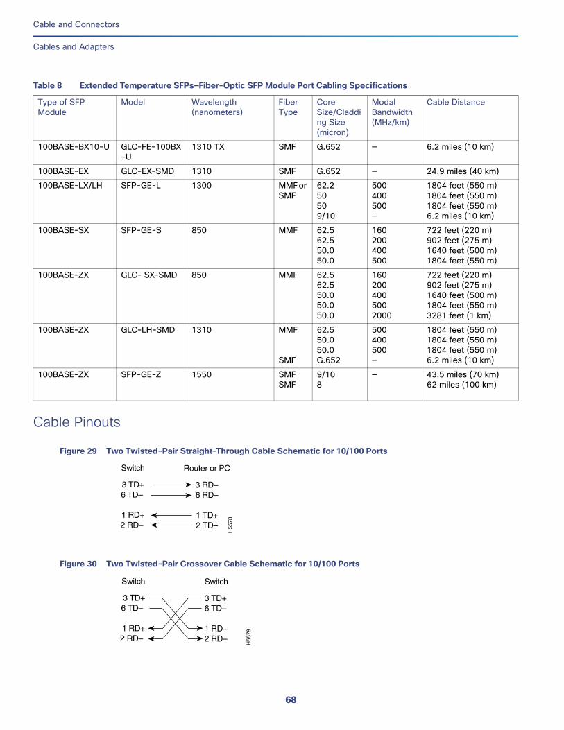
Cable and Connectors
Cables and Adapters
Cable Pinouts
Figure 29 Two Twisted-Pair Straight-Through Cable Schematic for 10/100 Ports
Figure 30 Two Twisted-Pair Crossover Cable Schematic for 10/100 Ports
Table 8 Extended Temperature SFPs—Fiber-Optic SFP Module Port Cabling Specifications
Type of SFP Module
Model Wavelength (nanometers)
Fiber Type
Core Size/Cladding Size (micron)
Modal Bandwidth (MHz/km)
Cable Distance
100BASE-BX10-U GLC-FE-100BX-U
1310 TX SMF G.652 — 6.2 miles (10 km)
100BASE-EX GLC-EX-SMD 1310 SMF G.652 — 24.9 miles (40 km)
100BASE-LX/LH SFP-GE-L 1300 MMF or SMF
62.250509/10
500400500—
1804 feet (550 m) 1804 feet (550 m) 1804 feet (550 m) 6.2 miles (10 km)
100BASE-SX SFP-GE-S 850 MMF 62.562.550.050.0
160200400500
722 feet (220 m)902 feet (275 m) 1640 feet (500 m) 1804 feet (550 m)
100BASE-ZX GLC- SX-SMD 850 MMF 62.562.550.050.050.0
1602004005002000
722 feet (220 m)902 feet (275 m) 1640 feet (500 m) 1804 feet (550 m)3281 feet (1 km)
100BASE-ZX GLC-LH-SMD 1310 MMF
SMF
62.550.050.0G.652
500400500—
1804 feet (550 m)1804 feet (550 m)1804 feet (550 m)6.2 miles (10 km)
100BASE-ZX SFP-GE-Z 1550 SMFSMF
9/108
— 43.5 miles (70 km) 62 miles (100 km)
Switch
3 TD+6 TD–
1 RD+2 RD–
Router or PC
3 RD+6 RD–
1 TD+2 TD–
H55
78
Switch
3 TD+6 TD–
1 RD+2 RD–
Switch
3 TD+6 TD–
1 RD+2 RD–
H55
79
68
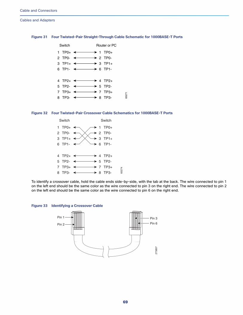
Cable and Connectors
Cables and Adapters
Figure 31 Four Twisted-Pair Straight-Through Cable Schematic for 1000BASE-T Ports
Figure 32 Four Twisted-Pair Crossover Cable Schematics for 1000BASE-T Ports
To identify a crossover cable, hold the cable ends side-by-side, with the tab at the back. The wire connected to pin 1 on the left end should be the same color as the wire connected to pin 3 on the right end. The wire connected to pin 2 on the left end should be the same color as the wire connected to pin 6 on the right end.
Figure 33 Identifying a Crossover Cable
1 TP0+
2 TP0-
3 TP1+
6 TP1-
1 TP0+
2 TP0-
3 TP1+
6 TP1-
Switch Router or PC
4 TP2+
5 TP2-
7 TP3+
8 TP3-
4 TP2+
5 TP2-
7 TP3+
8 TP3- 6527
11 TP0+
2 TP0-
3 TP1+
6 TP1-
1 TP0+
Switch Switch
2 TP0-
3 TP1+
6 TP1-
4 TP2+
5 TP2-
7 TP3+
8 TP3-
4 TP2+
5 TP2-
7 TP3+
8 TP3- 6527
4
Pin 1
Pin 2
2738
07
Pin 6
Pin 3
69
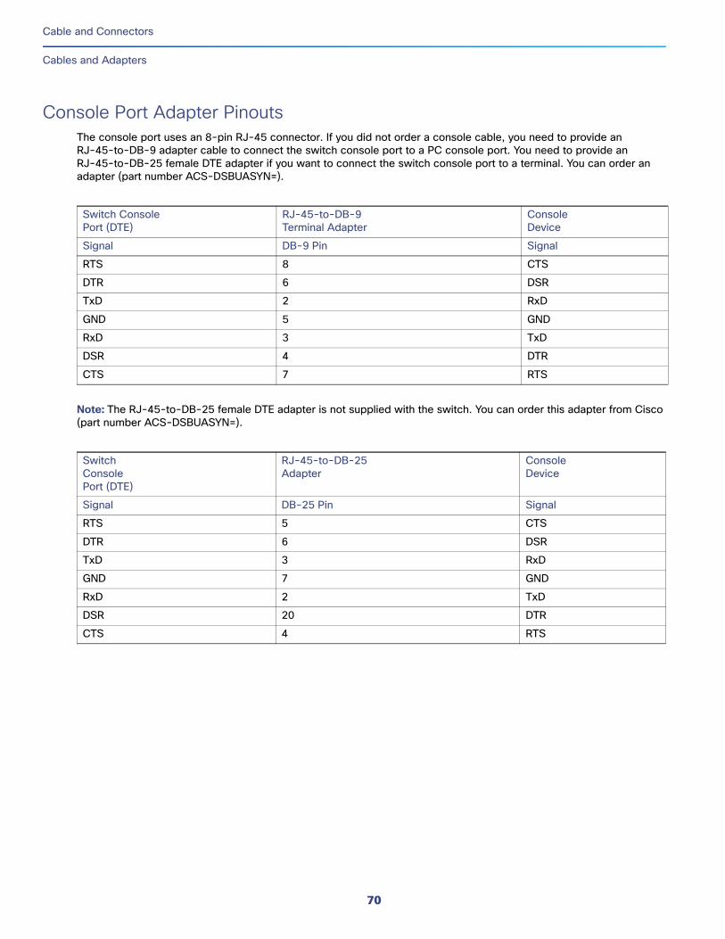
Cable and Connectors
Cables and Adapters
Console Port Adapter PinoutsThe console port uses an 8-pin RJ-45 connector. If you did not order a console cable, you need to provide an RJ-45-to-DB-9 adapter cable to connect the switch console port to a PC console port. You need to provide an RJ-45-to-DB-25 female DTE adapter if you want to connect the switch console port to a terminal. You can order an adapter (part number ACS-DSBUASYN=).
Note: The RJ-45-to-DB-25 female DTE adapter is not supplied with the switch. You can order this adapter from Cisco (part number ACS-DSBUASYN=).
Switch ConsolePort (DTE)
RJ-45-to-DB-9Terminal Adapter
ConsoleDevice
Signal DB-9 Pin Signal
RTS 8 CTS
DTR 6 DSR
TxD 2 RxD
GND 5 GND
RxD 3 TxD
DSR 4 DTR
CTS 7 RTS
SwitchConsolePort (DTE)
RJ-45-to-DB-25Adapter
ConsoleDevice
Signal DB-25 Pin Signal
RTS 5 CTS
DTR 6 DSR
TxD 3 RxD
GND 7 GND
RxD 2 TxD
DSR 20 DTR
CTS 4 RTS
70
Hazardous Location Installation InformationThis appendix provides hazardous location installation information for the Cisco IE 4000 switches.
Hazardous Area Installation WarningsWarning: Exposure to some chemicals could degrade the sealing properties of materials used in the sealed relay device. Statement 381
Warning: Failure to securely tighten the captive screws can result in an electrical arc if the connector is accidentally removed. Statement 397
Warning: When you connect or disconnect the power and/or alarm connector with power applied, an electrical arc can occur. This could cause an explosion in hazardous area installations. Be sure that all power is removed from the switch and any other circuits. Be sure that power cannot be accidentally turned on or verify that the area is nonhazardous before proceeding. Statement 1058
Warning: In switch installations in a hazardous location, the DC power source could be located away from the vicinity of the switch. Before performing any of the following procedures, locate the DC circuit to ensure that the power is removed and cannot be turned on accidentally, or verify that the area is nonhazardous before proceeding. Statement 1059
Warning: This equipment is supplied as “open type” equipment. It must be mounted within an enclosure that is suitably designed for those specific environmental conditions that will be present and appropriately designed to prevent personal injury resulting from accessibility to live parts. The interior of the enclosure must be accessible only by the use of a tool.
The enclosure must meet IP 54 or NEMA type 4 minimum enclosure rating standards. Statement 1063
Warning: When used in a Class I, Division 2, hazardous location, this equipment must be mounted in a suitable enclosure with proper wiring method, for all power, input and output wiring, that complies with the governing electrical codes and in accordance with the authority having jurisdiction over Class I, Division 2 installations. Statement 1066
Warning: Use twisted-pair supply wires suitable for 86°F (30°C) above surrounding ambient temperature outside the enclosure. Statement 1067
Warning: This equipment is intended for use in a Pollution Degree 2 industrial environment, in overvoltage Category II applications (as defined in IEC publication 60664-1), and at altitudes up to 2000 meters without derating. Statement 1068
Warning: Do not connect or disconnect cables to the ports while power is applied to the switch or any device on the network because an electrical arc can occur. This could cause an explosion in hazardous location installations. Be sure that power is removed from the switch and cannot be accidentally be turned on, or verify that the area is nonhazardous before proceeding. Statement 1070
Warning: If you connect or disconnect the console cable with power applied to the switch or any device on the network, an electrical arc can occur. This could cause an explosion in hazardous location installations. Be sure that power is removed or the area is nonhazardous before proceeding. Statement 1080
71
Cisco Systems, Inc. www.cisco.com
Hazardous Location Installation Information
Hazardous Area Installation Warnings
Warning: Explosion Hazard—Do not connect or disconnect wiring while the field-side power is on; an electrical arc can occur. This could cause an explosion in hazardous location installations. Be sure that power is removed or that the area is nonhazardous before proceeding. Statement 1081
Warning: Explosion Hazard—The area must be known to be nonhazardous before installing, servicing, or replacing the unit. Statement 1082
Warning: Explosion Hazard—Substitution of components may impair suitability for Class I, Division 2/Zone 2. Statement 1083
Warning: Do not insert and remove SFP modules while power is on; an electrical arc can occur. This could cause an explosion in hazardous location installations. Be sure that power is removed or the area is nonhazardous before proceeding. Statement 1087
Caution: This equipment is only suitable for use in Class I, Division 2, Groups A, B, C, D, or nonhazardous locations.
North American Hazardous Location ApprovalThe following information applies when operating this equipment in hazardous locations:
EMC Environmental Conditions for Products Installed in the European Union This section applies to products to be installed in the European Union.
The equipment is intended to operate under the following environmental conditions with respect to EMC:
A separate defined location under the user’s control.
Earthing and bonding shall meet the requirements of ETS 300 253 or CCITT K27.
AC-power distribution shall be one of the following types, where applicable: TN-S and TN-C as defined in IEC 364-3.
In addition, if equipment is operated in a domestic environment, interference could occur.
English: Products marked "Class I, Div 2, GP A, B, C, D" are suitable for use in Class I Division 2 Groups A, B, C, D, Hazardous Locations and nonhazardous locations only. Each product is supplied with markings on the rating nameplate indicating the hazardous location temperature code. When combining products within a system, the most adverse temperature code (lowest "T" number) may be used to help determine the overall temperature code of the system. Combinations of equipment in your system are subject to investigation by the local Authority Having Jurisdiction at the time of installation.
Français: Informations sur l'utilisation de cet équipement en environnements dangereux:
Les produits marqués "Class I, Div 2, GP A, B, C, D" ne conviennent qu'à une utilisation en environnements de Classe I Division 2 Groupes A, B, C, D dangereux et non dangereux. Chaque produit est livré avec des marquages sur sa plaque d'identification qui indiquent le code de température pour les environnements dangereux. Lorsque plusieurs produits sont combinés dans un système, le code de température le plus défavorable (code de température le plus faible) peut être utilisé pour déterminer le code de température global du système. Les combinaisons d'équipements dans le système sont sujettes à inspection par les autorités locales qualifiées au moment de l'installation.
72
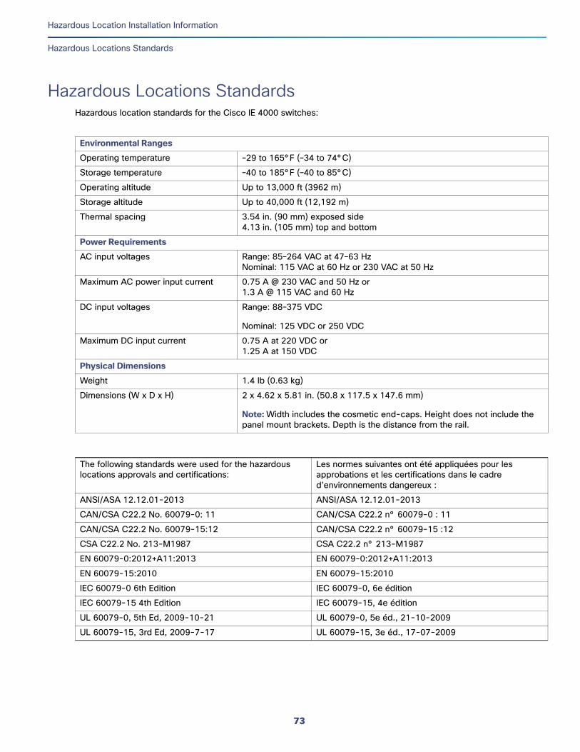
Hazardous Location Installation Information
Hazardous Locations Standards
Hazardous Locations StandardsHazardous location standards for the Cisco IE 4000 switches:
Environmental Ranges
Operating temperature –29 to 165°F (–34 to 74°C)
Storage temperature –40 to 185°F (–40 to 85°C)
Operating altitude Up to 13,000 ft (3962 m)
Storage altitude Up to 40,000 ft (12,192 m)
Thermal spacing 3.54 in. (90 mm) exposed side4.13 in. (105 mm) top and bottom
Power Requirements
AC input voltages Range: 85–264 VAC at 47–63 HzNominal: 115 VAC at 60 Hz or 230 VAC at 50 Hz
Maximum AC power input current 0.75 A @ 230 VAC and 50 Hz or1.3 A @ 115 VAC and 60 Hz
DC input voltages Range: 88–375 VDC
Nominal: 125 VDC or 250 VDC
Maximum DC input current 0.75 A at 220 VDC or1.25 A at 150 VDC
Physical Dimensions
Weight 1.4 lb (0.63 kg)
Dimensions (W x D x H) 2 x 4.62 x 5.81 in. (50.8 x 117.5 x 147.6 mm)
Note: Width includes the cosmetic end-caps. Height does not include the panel mount brackets. Depth is the distance from the rail.
The following standards were used for the hazardous locations approvals and certifications:
Les normes suivantes ont été appliquées pour les approbations et les certifications dans le cadre d'environnements dangereux :
ANSI/ASA 12.12.01-2013 ANSI/ASA 12.12.01-2013
CAN/CSA C22.2 No. 60079-0: 11 CAN/CSA C22.2 n° 60079-0 : 11
CAN/CSA C22.2 No. 60079-15:12 CAN/CSA C22.2 n° 60079-15 :12
CSA C22.2 No. 213-M1987 CSA C22.2 n° 213-M1987
EN 60079-0:2012+A11:2013 EN 60079-0:2012+A11:2013
EN 60079-15:2010 EN 60079-15:2010
IEC 60079-0 6th Edition IEC 60079-0, 6e édition
IEC 60079-15 4th Edition IEC 60079-15, 4e édition
UL 60079-0, 5th Ed, 2009-10-21 UL 60079-0, 5e éd., 21-10-2009
UL 60079-15, 3rd Ed, 2009-7-17 UL 60079-15, 3e éd., 17-07-2009
73

Hazardous Location Installation Information
Hazardous Locations Standards
74
Related Documents