© 2012 Cisco and/or its affiliates. All rights reserved. This document is Cisco Public Information. Page 1 of 1 White Paper All Beamforming Solutions Are Not Equal Executive Summary This white paper compares and contrasts the two major implementations of beamforming found in the market today: ● Switched array beamforming ● Digital signal processing (DSP)-based beamforming This paper suggests that both methods do offer some performance gain but that DSP-based beamforming (such as used in ClientLink 2.0) is superior (especially when supporting a network with many clients) and therefore preferred for the following reasons: ● DSP-based techniques are used in 11n chipsets to improve uplink performance. These same DSP techniques can also be used to improve downlink performance. Switched arrays only improve downlink. ● DSP-based beamforming using multiple transmitters for downlink performance improvement is aided by using information acquired from multiple receivers during uplink performance improvement. A switched array cannot easily exploit information acquired in the uplink. ● DSP-based techniques can respond more rapidly to fluctuating RF conditions and therefore can support more clients. ● DSP-based techniques are better suited to orthogonal frequency-division multiplexing (OFDM)/(MIMO) multiple-input and multiple-output because the transmission of each subcarrier and each RF chain can be fine tuned for frequency selective fading (as typical in the wireless channel). Switched arrays do not have the ability to optimize per OFDM subcarrier or RF chain. ● DSP-based techniques are measurably better and validate theoretical/simulated analyses. 1. Introduction As 802.11n systems propagate in the market, beamforming is emerging as an important feature for enterprise Wi-Fi infrastructure. In order to understand why, the first thing to note is that 11n radios on the infrastructure (access point, or AP) side tend to have considerably more transceivers than on the client side. For example, an 11n enterprise-class AP typically has three or four transceivers, whereas an 11n client such as a cell phone or tablet typically has only a single transceiver. Even laptops are often limited to one or two transceivers. The simple reasons for this are size and power (and sometimes cost). It’s very difficult to squeeze multiple antennas onto a mobile device, and the mobile devices are constrained by running off battery. So, in a typical enterprise scenario, we might have a 4x4 AP and a 1x1 client.

Cisco Beamforming Solutions
Dec 31, 2015
Cisco Beamforming Solutions
Welcome message from author
This document is posted to help you gain knowledge. Please leave a comment to let me know what you think about it! Share it to your friends and learn new things together.
Transcript
© 2012 Cisco and/or its affiliates. All rights reserved. This document is Cisco Public Information. Page 1 of 1
White Paper
All Beamforming Solutions Are Not Equal
Executive Summary
This white paper compares and contrasts the two major implementations of beamforming found in the market
today:
● Switched array beamforming
● Digital signal processing (DSP)-based beamforming
This paper suggests that both methods do offer some performance gain but that DSP-based beamforming (such
as used in ClientLink 2.0) is superior (especially when supporting a network with many clients) and therefore
preferred for the following reasons:
● DSP-based techniques are used in 11n chipsets to improve uplink performance. These same DSP
techniques can also be used to improve downlink performance. Switched arrays only improve downlink.
● DSP-based beamforming using multiple transmitters for downlink performance improvement is aided by
using information acquired from multiple receivers during uplink performance improvement. A switched
array cannot easily exploit information acquired in the uplink.
● DSP-based techniques can respond more rapidly to fluctuating RF conditions and therefore can support
more clients.
● DSP-based techniques are better suited to orthogonal frequency-division multiplexing (OFDM)/(MIMO)
multiple-input and multiple-output because the transmission of each subcarrier and each RF chain can be
fine tuned for frequency selective fading (as typical in the wireless channel). Switched arrays do not have
the ability to optimize per OFDM subcarrier or RF chain.
● DSP-based techniques are measurably better and validate theoretical/simulated analyses.
1. Introduction
As 802.11n systems propagate in the market, beamforming is emerging as an important feature for enterprise
Wi-Fi infrastructure.
In order to understand why, the first thing to note is that 11n radios on the infrastructure (access point, or AP) side
tend to have considerably more transceivers than on the client side. For example, an 11n enterprise-class AP
typically has three or four transceivers, whereas an 11n client such as a cell phone or tablet typically has only a
single transceiver. Even laptops are often limited to one or two transceivers. The simple reasons for this are size
and power (and sometimes cost). It’s very difficult to squeeze multiple antennas onto a mobile device, and the
mobile devices are constrained by running off battery. So, in a typical enterprise scenario, we might have a 4x4 AP
and a 1x1 client.
© 2012 Cisco and/or its affiliates. All rights reserved. This document is Cisco Public Information. Page 2 of 11
With this combination of transceiver counts, only a single spatial stream may be transmitted in either direction,
because the number of spatial streams is limited by the side of the link with the fewest antennas. But when
transmitting a single spatial stream in this scenario, the uplink performance (traffic from client to AP) can be better
than the downlink performance (traffic from AP to client). The reason for this is that in the uplink direction, the
multiple receivers on the AP allow for combining gain, resulting in improved signal.
Beamforming is the primary method of improving downlink performance (AP to client) that takes advantage of the
multiple MIMO transmitters on the AP. The use of beamforming on the downlink transmissions often results in a
more balanced level of performance between uplink and downlink. And because traffic load tends to be greater in
the downlink direction, achieving this balance results in better overall system performance.
Two basic types of beamforming have been introduced to the Wi-Fi enterprise market: switched antenna arrays
(Ruckus) and DSP-based beamforming (Cisco). This paper will examine the differences between these
approaches and demonstrate why the DSP-based approach is superior.
2. Types of Beamforming
As just described, there are two types of beamforming in the market. Note that both of these approaches improve
the signal in the downlink direction, but do not generally have any effect in the uplink direction.
2.1. Switched Antenna Arrays This type of beamforming is based on a switched antenna array, which allows selection of different directional
antenna patterns. One type of switched antenna array is sometimes referred to as a “pin diode” array. Essentially,
the antenna pattern is changed by enabling certain antenna elements and disabling (grounding) others. The
combination of elements that are enabled vs. disabled results in different propagation patterns. For example, if you
have an antenna with 4 elements per transceiver, then that allows for 15 possible patterns per antenna. (There
would be 16 patterns in all, but the case of all elements disabled isn’t effective.) If we consider a 3-transceiver AP,
each with 4 antenna elements, then that would provide up to 15 x 15 x 15 = 3375 theoretical MIMO patterns. By
experimenting with different MIMO patterns, the idea is that the AP can identify the MIMO pattern that seems to
have the best downlink performance for a given client location.
Another type of switched antenna array has individual elements that are directional and are organized in a
sectorized pattern. For example, twelve antennas could be configured with six antennas each covering 60 degrees
around the AP, with two types of polarization. The AP can again experiment with which combination of antenna
element(s) provides the best downlink performance. (See Figure 1.)
© 2012 Cisco and/or its affiliates. All rights reserved. This document is Cisco Public Information. Page 3 of 11
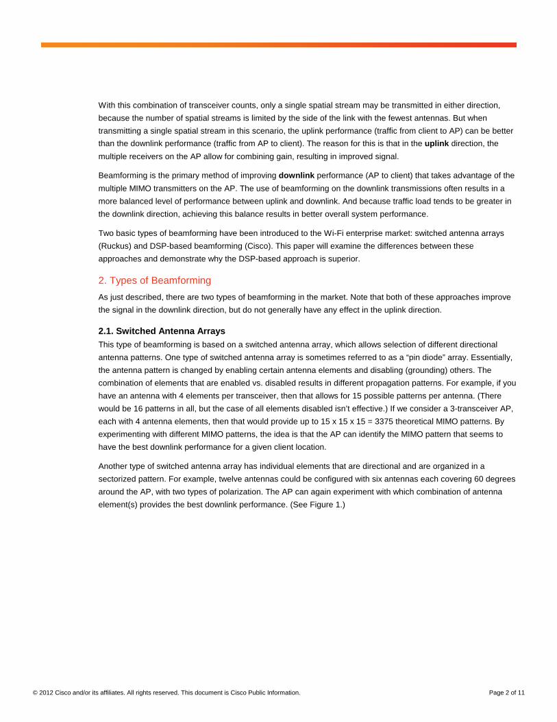
Figure 1. Example Antenna Patterns from Switched Antenna Array
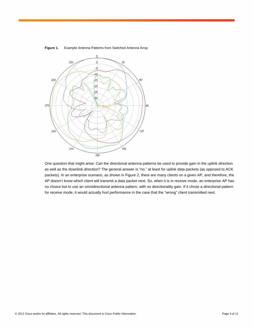
One question that might arise: Can the directional antenna patterns be used to provide gain in the uplink direction
as well as the downlink direction? The general answer is “no,” at least for uplink data packets (as opposed to ACK
packets). In an enterprise scenario, as shown in Figure 2, there are many clients on a given AP, and therefore, the
AP doesn’t know which client will transmit a data packet next. So, when it is in receive mode, an enterprise AP has
no choice but to use an omnidirectional antenna pattern, with no directionality gain. If it chose a directional pattern
for receive mode, it would actually hurt performance in the case that the “wrong” client transmitted next.
© 2012 Cisco and/or its affiliates. All rights reserved. This document is Cisco Public Information. Page 4 of 11
Figure 2. Showing Why Directional Antenna Patterns Cannot Be Used for Uplink Traffic
2.2. DSP-Based Beamforming This type of beamforming does not require an antenna array but uses a more traditional single antenna element
per transceiver. Instead, this method uses DSP techniques to adjust the phase and amplitude (power) of the
signals transmitted at each antenna. By varying the phase and amplitude of the transmitted signal, the AP is able
to arrange that the signal received at the client has constructive interference, thus increasing signal quality at the
client.
2.2.1. How DSP Beamforming Works
To understand how this works, let’s first take the case of an 802.11a/g/n client with a single transceiver sending an
uplink packet to a Cisco® 802.11n AP with four MIMO transceivers. When the AP receives the packet, it actually
receives four different signals (one on each receive antenna). Each received signal has a different phase and
amplitude based on the physical characteristics of the space (or path) between an antenna on the AP and the
antenna on the client. Using signal processing, the AP is able to combine the four signals received by multipath
into one reinforced signal by adjusting the phases and amplitudes of the received signals in order to form the best
possible signal. The algorithm that performs this combination is called maximal ratio combining (MRC) for a single
stream transmission. For multistream transmissions, it gets a bit more complex, but the general algorithms can be
referred to as MIMO equalization. Figure 3 provides an illustration of the benefits of MRC in compensating for
fades in any receive path and producing a good signal overall.
© 2012 Cisco and/or its affiliates. All rights reserved. This document is Cisco Public Information. Page 5 of 11
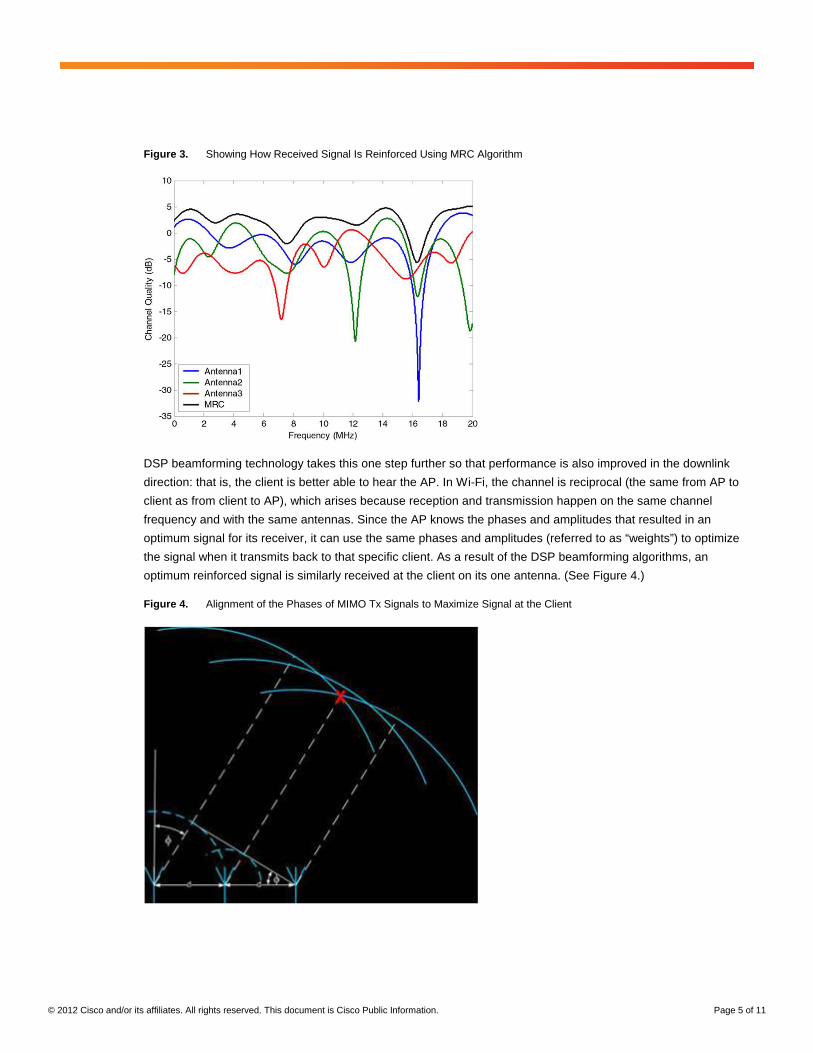
Figure 3. Showing How Received Signal Is Reinforced Using MRC Algorithm
DSP beamforming technology takes this one step further so that performance is also improved in the downlink
direction: that is, the client is better able to hear the AP. In Wi-Fi, the channel is reciprocal (the same from AP to
client as from client to AP), which arises because reception and transmission happen on the same channel
frequency and with the same antennas. Since the AP knows the phases and amplitudes that resulted in an
optimum signal for its receiver, it can use the same phases and amplitudes (referred to as “weights”) to optimize
the signal when it transmits back to that specific client. As a result of the DSP beamforming algorithms, an
optimum reinforced signal is similarly received at the client on its one antenna. (See Figure 4.)
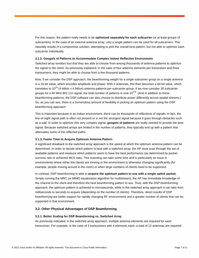
Figure 4. Alignment of the Phases of MIMO Tx Signals to Maximize Signal at the Client

© 2012 Cisco and/or its affiliates. All rights reserved. This document is Cisco Public Information. Page 6 of 11
Note that an 802.11a/g/n signal uses a modulation scheme called orthogonal frequency-division multiplexing
(OFDM), which uses multiple subcarriers. Because these subcarriers are separated in frequency, each subcarrier
can actually have different channel characteristics between the AP and the client. For this reason, separate
phases and amplitudes are calculated and stored for each subcarrier. We will discuss this again later, in the
section on advantages of DSP beamforming, because it is a major factor behind the performance gain of DSP
beamforming.
2.2.2. DSP Beamforming Works with All Clients
It’s important to point out that the DSP beamforming technology described in section 2.2.1 can be implemented
without any special client-side hardware or software capabilities. Therefore, the beamforming works with all
existing 802.11 a/g/n clients. An example of this type of DSP beamforming is Cisco’s ClientLink 2.0, which is
implemented in the Cisco 3600 Series APs and works with all clients (and can support up to 128 clients in a mix of
802.11 a/g/n clients). This type of beamforming should not be confused with the multiple optional beamforming
methods that are part of the 11n standard, which are not generally implemented in clients. The 11n methods of
beamforming require the receiving device (client) to share channel state information with the transmitting device
(AP) in order for beamforming to work. Since in practice, very few clients implement (or enable) support for
802.11n beamforming, it does not currently provide practical benefits, and it is not expected that this will change
over time. A brief overview of standards-based beamforming is included in a white paper here:
http://www.cisco.com/en/US/prod/collateral/wireless/ps5678/ps11983/white_paper_c11-688713.html.
The 802.11ac standard also defines a single optional method of DSP beamforming, which is expected to be more
widely supported in clients. But unfortunately, the 11ac beamforming method is not backward compatible with 11n
chipsets. Therefore, 11ac beamforming will only provide benefit when you have both an 11ac AP and an 11ac
client and they both support 11ac beamforming.
Note that some vendors have claimed that DSP beamforming without client participation is not effective because
differences in the client's Tx path and Rx path degrade the reciprocity of the channel. This claim is misguided,
because the Rx path has very little effect on the performance of beamforming. The only component of the over-
the-air channel that needs to be reciprocal is between the client's antennas and the AP's Rx and Tx. Therefore, to
maintain reciprocity, the AP only needs to calibrate out differences in its own Rx and Tx paths (which Cisco indeed
does), and any effect from the client's Tx phase completely cancels itself out during computation of the
beamforming matrix.
3. Advantages of DSP Beamforming over Switched Antenna Beamforming
Although the switched antenna approach to beamforming does provide some benefit, there are significant
advantages to DSP-based beamforming. This section will cover the main benefits.
3.1. Performance Advantages of DSP Beamforming
3.1.1. Per-Subcarrier Optimization
The first primary advantage of DSP beamforming is that, as previously discussed, it is able to optimize the signal
on a per-subcarrier basis. Remember that 40 MHz 802.11n signals have 114 subcarriers (both data and pilots),
and 80 MHz 802.11ac signals have 242 subcarriers. The subcarriers of the OFDM signal are spread across these
wide channels, and the signals bounce in very different ways across the frequencies. As can be seen in Figure 3,
what is right at 1 MHz into the channel, where we want to emphasize antenna 1, is completely wrong at 16.5 MHz
into the channel, where we should emphasize antenna 3 instead.
© 2012 Cisco and/or its affiliates. All rights reserved. This document is Cisco Public Information. Page 7 of 11
For this reason, the pattern really needs to be optimized separately for each subcarrier (or at least groups of
subcarriers). In the case of an external antenna array, only a single pattern can be used for all subcarriers. This
naturally results in a compromise solution, attempting to pick the overall best pattern, but not able to optimize each
subcarrier individually.
3.1.2. Googols of Patterns to Accommodate Complex Indoor Reflective Environment
Switched array vendors tout that they are able to choose from among thousands of antenna patterns to optimize
the signal to the client. As previously explained, in the case of four antenna elements per transceiver and three
transceivers, they might be able to choose from a few thousand patterns.
Now, if we consider the DSP approach, the beamforming weight for a single subcarrier group on a single antenna
is a 16-bit value, which encodes amplitude and phase. With 4 antennas, this then becomes a 64-bit value, which
translates to 1019 (4 billion x 4 billion) antenna patterns per subcarrier group. If we now consider 30 subcarrier
groups for a 40 MHz 802.11n signal, the total number of patterns is now 10578. (And in addition to these
beamforming patterns, the DSP software can also choose to distribute power differently across spatial streams.)
So, as you can see, there is a tremendous amount of flexibility in picking an optimum pattern using the DSP
beamforming approach.
This is important because in an indoor environment, there can be thousands of reflections of signals. In fact, the
line-of-sight signal path is often not present or is not the strongest signal because it goes through obstacles such
as a wall. In order to optimize this very complex signal, googols of patterns are really needed to provide the best
signal. Because switched arrays are limited in the number of patterns, they typically end up with a pattern that
attenuates some of the reflected paths.
3.1.3. Faster Time to Acquire Optimum Antenna Pattern
A significant drawback to the switched array approach is the speed at which the optimum antenna pattern can be
determined. In order to decide which pattern is best with a switched array, the AP must scan through the set of
available patterns and measure which patterns seem to have the best performance (as determined by packet
success rate or achieved MCS rate). This scanning can take some time and is particularly an issue in
environments where either the clients are moving or the environment is otherwise changing significantly (for
example, people moving around in the room) or when large numbers of clients need to be supported.
In contrast, DSP beamforming is able to acquire the optimum pattern to use with a single uplink packet.
Simply running the MRC (or MIMO equalization algorithm for multistream), the AP has immediate knowledge of
the channel to the client and therefore the best beamforming pattern to use. Thus, with the DSP beamforming
approach, the optimum pattern is achieved in microseconds, while in the switched array approach it can take from
milliseconds to seconds to acquire (depending on the number of clients). Therefore, direct results of DSP
beamforming are better support for rapidly changing RF environments and a greater number of clients that can be
supported in that environment.
3.2. Other Physical Advantages of DSP Beamforming
3.2.1. Better Scaling for DSP Beamforming vs. Switched Array
As previously indicated, in the switched array approach, multiple antenna elements are required for each
transceiver. For example, in the case of 3 transceivers with 4 elements each, a total of 12 antennas are required.
© 2012 Cisco and/or its affiliates. All rights reserved. This document is Cisco Public Information. Page 8 of 11
A trend in 802.11n and 802.11ac systems has been adding more transceivers over time. For example, early
802.11n APs had two or three transceivers, but a state-of-the-art enterprise AP now has four transceivers. And
with 802.11ac wave 2, we might see systems with more than four transceivers. (The 11ac standard defines up to
eight spatial streams, which would require a minimum of eight transceivers.) As the number of transceivers grows,
the number of antenna elements grows as a multiple, and this will be both a size and cost issue for the switched
array approach.
3.2.2. DSP Beamforming Does Not Need RF Switches
A second physical issue with the switched array approach is the switches themselves, which are required for
enabling or disabling individual antenna elements to form the pattern. These switches can cause loss in the
transmitted signal, which partially offsets the gain from choosing a good directional pattern for the client. With the
DSP beamforming approach, there is no signal loss due to switches because switches are not used.
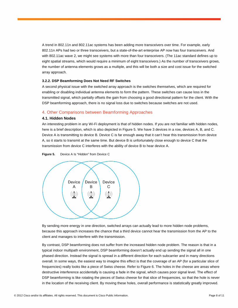
4. Other Comparisons between Beamforming Approaches 4.1. Hidden Nodes An interesting problem in any Wi-Fi deployment is that of hidden nodes. If you are not familiar with hidden nodes,
here is a brief description, which is also depicted in Figure 5. We have 3 devices in a row, devices A, B, and C.
Device A is transmitting to device B. Device C is far enough away that it can’t hear this transmission from device
A, so it starts to transmit at the same time. But device B is unfortunately close enough to device C that the
transmission from device C interferes with the ability of device B to hear device A.
Figure 5. Device A Is “Hidden” from Device C
By sending more energy in one direction, switched arrays can actually lead to more hidden node problems,
because this approach increases the chance that a third device cannot hear the transmission from the AP to the
client and manages to interfere with the transmission.
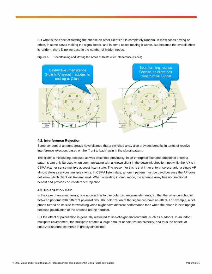
By contrast, DSP beamforming does not suffer from the increased hidden node problem. The reason is that in a
typical indoor multipath environment, DSP beamforming doesn’t actually end up sending the signal all in one
phased direction. Instead the signal is spread in a different direction for each subcarrier and in many directions
overall. In some ways, the easiest way to imagine this effect is that the coverage of an AP (for a particular slice of
frequencies) really looks like a piece of Swiss cheese. Refer to Figure 6. The holes in the cheese are areas where
destructive interference accidentally is causing a fade in the signal, which causes poor signal level. The effect of
DSP beamforming is like rotating the pieces of Swiss cheese for that slice of frequencies, so that the hole is never
in the location of the receiving client. By moving these holes, overall performance is statistically greatly improved.
© 2012 Cisco and/or its affiliates. All rights reserved. This document is Cisco Public Information. Page 9 of 11
But what is the effect of rotating the cheese on other clients? It is completely random, in most cases having no
effect, in some cases making the signal better, and in some cases making it worse. But because the overall effect
is random, there is no increase in the number of hidden nodes.
Figure 6. Beamforming and Moving the Areas of Destructive Interference (Fades)
4.2. Interference Rejection Some vendors of antenna arrays have claimed that a switched array also provides benefits in terms of receive
interference rejection, based on the “front to back” gain in the signal pattern.
This claim is misleading, because as was described previously, in an enterprise scenario directional antenna
patterns can only be used when communicating with a known client in the downlink direction, not while the AP is in
CSMA (carrier sense multiple access) listen state. The reason for this is that in an enterprise scenario, a single AP
almost always services multiple clients. In CSMA listen state, an omni pattern must be used because the AP does
not know which client will transmit next. When operating in omni mode, the antenna array has no directional
benefit and provides no interference rejection.
4.3. Polarization Gain In the case of antenna arrays, one approach is to use polarized antenna elements, so that the array can choose
between patterns with different polarizations. The polarization of the signal can have an effect. For example, a cell
phone turned on its side for watching video might have different performance than when the phone is held upright
because polarization of the antenna on the handset.
But the effect of polarization is generally restricted to line-of-sight environments, such as outdoors. In an indoor
multipath environment, the multipath creates a large amount of polarization diversity, and thus the benefit of
polarized antenna elements is greatly diminished.
© 2012 Cisco and/or its affiliates. All rights reserved. This document is Cisco Public Information. Page 10 of 11
5. Analysis of Beamforming Gains Between the Two Approaches
At the end of the day, the true benefit of a beamforming solution can be measured in terms of the average gain in
the signal delivered at the desired client.
5.1. Switched Array Beamforming Gain For the switched array case, the gain is a result of the directional gain of the antenna pattern that has been
chosen. Since different patterns are used at different times, we can look at the average directional gain of the
various patterns. But note that for the indoor multipath environment, we need to subtract a few dBs, because even
with the optimum pattern, some reflected signals that would normally make it to the client will actually be reduced.
As an example, we can look at the Ruckus 7982 AP, where the claim is for an average “adaptive antenna gain” of
6 dB. Note that for the 7962, Ruckus also claims an additional 3 dB of gain from standards-based 802.11n
beamforming. As discussed in section 2.2.2, this claim is highly optimistic, since very few clients implement 11n
beamforming. Ruckus indicates that this gain will be realized “once client compatibility becomes ubiquitous in the
years ahead.” But this might be an unrealistic presumption, because there is no strong indication that 11n clients
will be adding support for 11n beamforming at any point in the future.
5.2. DSP Beamforming Gain For DSP beamforming, we can look to theory based on channel mathematical models. Some of the gain is a result
of “array gain,” and some is a result of equalizing the channel. The array gain refers to the directionality of the
actual beam pattern. In other words, array gain is the ability of the beamformer to “point” the beam at the client.
The array gain can be directly calculated as follows:
GArray = 10Log10(nTx/nSS)
Although array gain provides a nice boost in RSSI (received signal strength indicator) to the client, it fails to fully
characterize the benefit to clients that have uneven RSSI across the full signal bandwidth. In most indoor non-line-
of-sight (NLOS) environments, the over-the-air channel changes significantly across the full 40-MHz channel and
is often referred to as a frequency-selective fading channel. Therefore, even though the signal might be well
received in one group of subcarriers, it is common to see other subcarrier groups received at powers significantly
below the rest (as the example shows in Figure 3, fades can be 30 dB or more). These deep frequency selective
fades are what makes subcarrier-by-subcarrier beamforming tremendously important.
Since the clients typically don’t have extra receive antennas for MIMO equalization, the job of improving the
channel falls to the AP beamformer. And this is exactly what DSP beamforming does very well, since it beamforms
each subcarrier group individually.
Although the array gain can be directly calculated, determining the overall beamforming gain (including subcarrier-
by-subcarrier gain) cannot simply be calculated and instead requires simulation with channel models. For
example, a simulation was done with the following model parameters:
● 4x4 802.11n AP sending at the highest possible 802.11n data rate (64-QAM 5/6)
● 1x1, 2x2, and 3x3 802.11n clients
● IEEE 11n channel model: D (NLOS)
● Client receivers: MMSE
● Phase noise: -35 dB
● Tx EVM: -33 dB
© 2012 Cisco and/or its affiliates. All rights reserved. This document is Cisco Public Information. Page 11 of 11
The simulation results for total DSP beamforming gain, which includes both array gain and subcarrier-by-
subcarrier beamforming gain components, show that typical gain is from 7 to 12 dB. This exceeds the typical gain
for the switched array approach.
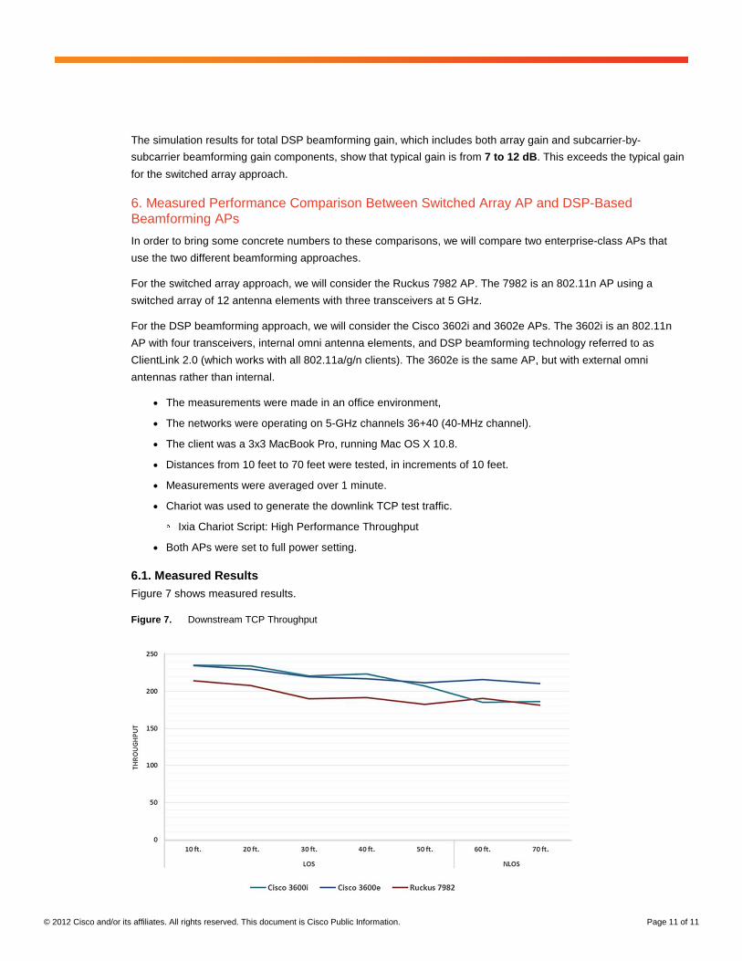
6. Measured Performance Comparison Between Switched Array AP and DSP-Based Beamforming APs
In order to bring some concrete numbers to these comparisons, we will compare two enterprise-class APs that
use the two different beamforming approaches.
For the switched array approach, we will consider the Ruckus 7982 AP. The 7982 is an 802.11n AP using a
switched array of 12 antenna elements with three transceivers at 5 GHz.
For the DSP beamforming approach, we will consider the Cisco 3602i and 3602e APs. The 3602i is an 802.11n
AP with four transceivers, internal omni antenna elements, and DSP beamforming technology referred to as
ClientLink 2.0 (which works with all 802.11a/g/n clients). The 3602e is the same AP, but with external omni
antennas rather than internal.
● The measurements were made in an office environment,
● The networks were operating on 5-GHz channels 36+40 (40-MHz channel).
● The client was a 3x3 MacBook Pro, running Mac OS X 10.8.
● Distances from 10 feet to 70 feet were tested, in increments of 10 feet.
● Measurements were averaged over 1 minute.
● Chariot was used to generate the downlink TCP test traffic. ◦ Ixia Chariot Script: High Performance Throughput
● Both APs were set to full power setting.
6.1. Measured Results Figure 7 shows measured results.
Figure 7. Downstream TCP Throughput
© 2012 Cisco and/or its affiliates. All rights reserved. This document is Cisco Public Information. Page 12 of 11
7. Summary
As the paper has shown, beamforming has become an important feature for 802.11n (and beyond) enterprise-
class APs, because it helps to normalize uplink and downlink performance and increase capacity of the network.
There are two main approaches to beamforming currently available in the market: switched arrays and DSP
beamforming. Although both provide some benefit, the DSP beamforming approach has been shown to have
many advantages (including better performance) that make it by far the preferred solution. This is why Cisco has
implemented the industry’s best DSP beamforming solution - ClientLink 2.0 - in the 3600 Series APs. Additional
details about ClientLink 2.0 can be found at
http://www.cisco.com/en/US/prod/collateral/wireless/ps5678/ps11983/white_paper_c11-688713.html.
Printed in USA C11-722622-00 01/13
Related Documents