Cleanability: CIP/SIP Sterile Connections and Transfers High Purity Valves and Magnetic Mixers The possibility of contamination lurks as a constant threat during aseptic filling of injectable drugs that cannot be terminally heat-sterilized. The risk of contamination occurs when being filled through the open clean room air into a final container. Much greater quality control is now possible thanks to advances in barrier technology at the filling machine and clever valve design. The method detailed in this article shows how to use ASEPCO Valves in a validated sterile connection/transfer. Process equipment design is a critical part of the plan for all sterile processes. One must find a method to connect the sterile bulk hold tank (often portable) to the sterile filling machine — without contamination — that can be validated through challenge testing. Technically, this is a significant obstacle to overcome. The valves must seal with absolute reliability, dead legs must be eliminated, and drainability must be a certainty. All connections must be steamed-in-place (SIP) before any fluid transfer is made. Certain flowpaths might also need to be cleaned-in-place (CIP), followed by SIP. When ported, ASEPCO Radial-Diaphragm ™ Valves create a behind-the-seat flowpath inside the valve’s body. The Process Valve is the workhorse of the sterile connection/ transfer system. Drawing 1 Creating this special flowpath between ASEPCO Valves makes it possible to first connect the two sterile systems, sterilize the space between them, and subsequently carry out a sterile fluid transfer. This system is rather like two ships meeting in outer space to exchange passengers. First the two ships must dock, while remaining sealed. Then, the airlock created by this docking must be filled with air prior to its use. The ships are then each unsealed to the airlock (and each other), allowing people to move between them. In much the same way, two sealed, sterile systems are first docked to each other — with the valves closed — keeping each sterile system sealed. Steam is then introduced to sterilize the airlock between the two systems, before the transfer takes place. Once SIP is complete, the valves sealing each sterile system can be safely opened to permit fluid transfer. Follow-up CIP/ SIP can provide a decontamination step, if necessary. While manual valves are used to illustrate the sterile connection in the drawings below, the system actually relies on pneumatically operated ASEPCO Valves. This reduces the possibility for error in valve sequencing. In Drawings 2 and 3, we see the two parts of the system. Drawing 2 shows the filled tank with its drain valve (V5) and docking valve (V4). Prior to the tank being filled, V4 and V5 were SIP in the open position (with the tank) and then closed to allow the tank to be filled. The tank system is ready for transport to the filling area. Drawing 2 1

Welcome message from author
This document is posted to help you gain knowledge. Please leave a comment to let me know what you think about it! Share it to your friends and learn new things together.
Transcript
Cleanability: CIP/SIP Sterile Connections and Transfers
High Purity Valves and Magnetic Mixers
The possibility of contamination lurks as a constant threat during aseptic filling of injectable drugs that cannot be terminally heat-sterilized. The risk of contamination occurs when being filled through the open clean room air into a final container. Much greater quality control is now possible thanks to advances in barrier technology at the filling machine and clever valve design. The method detailed in this article shows how to use ASEPCO Valves in a validated sterile connection/transfer.
Process equipment design is a critical part of the plan for all sterile processes. One must find a method to connect the sterile bulk hold tank (often portable) to the sterile filling machine — without contamination — that can be validated through challenge testing. Technically, this is a significant obstacle to overcome. The valves must seal with absolute reliability, dead legs must be eliminated, and drainability must be a certainty. All connections must be steamed-in-place (SIP) before any fluid transfer is made. Certain flowpaths might also need to be cleaned-in-place (CIP), followed by SIP.
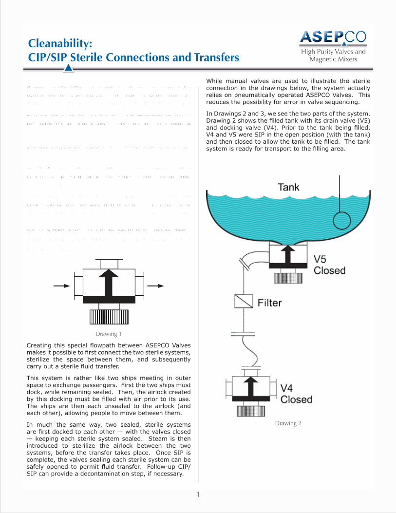
When ported, ASEPCO Radial-Diaphragm™ Valves create a behind-the-seat flowpath inside the valve’s body. The Process Valve is the workhorse of the sterile connection/transfer system.
Drawing 1
Creating this special flowpath between ASEPCO Valves makes it possible to first connect the two sterile systems, sterilize the space between them, and subsequently carry out a sterile fluid transfer.
This system is rather like two ships meeting in outer space to exchange passengers. First the two ships must dock, while remaining sealed. Then, the airlock created by this docking must be filled with air prior to its use. The ships are then each unsealed to the airlock (and each other), allowing people to move between them.
In much the same way, two sealed, sterile systems are first docked to each other — with the valves closed — keeping each sterile system sealed. Steam is then introduced to sterilize the airlock between the two systems, before the transfer takes place. Once SIP is complete, the valves sealing each sterile system can be safely opened to permit fluid transfer. Follow-up CIP/SIP can provide a decontamination step, if necessary.
While manual valves are used to illustrate the sterile connection in the drawings below, the system actually relies on pneumatically operated ASEPCO Valves. This reduces the possibility for error in valve sequencing.
In Drawings 2 and 3, we see the two parts of the system. Drawing 2 shows the filled tank with its drain valve (V5) and docking valve (V4). Prior to the tank being filled, V4 and V5 were SIP in the open position (with the tank) and then closed to allow the tank to be filled. The tank system is ready for transport to the filling area.
Drawing 2
1
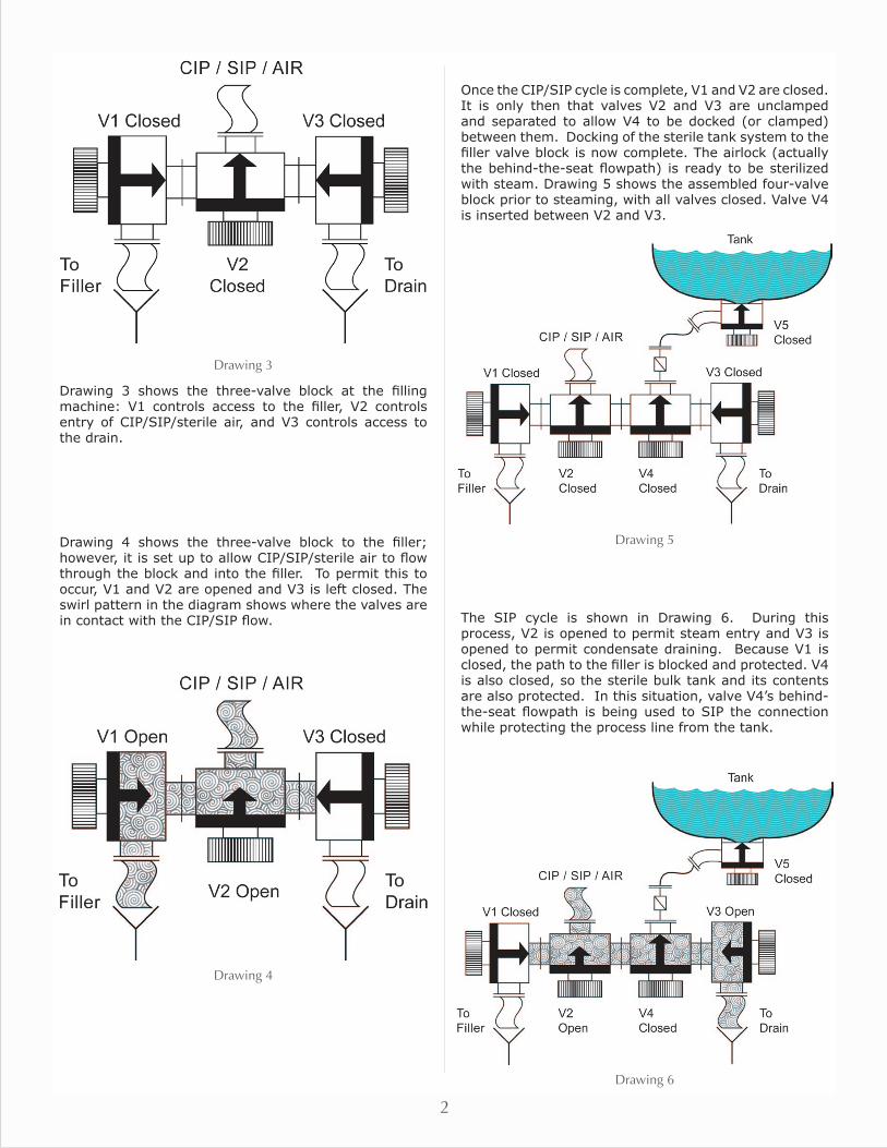
Drawing 3
Drawing 3 shows the three-valve block at the filling machine: V1 controls access to the filler, V2 controls entry of CIP/SIP/sterile air, and V3 controls access to the drain.
Drawing 4 shows the three-valve block to the filler; however, it is set up to allow CIP/SIP/sterile air to flow through the block and into the filler. To permit this to occur, V1 and V2 are opened and V3 is left closed. The swirl pattern in the diagram shows where the valves are in contact with the CIP/SIP flow.
Drawing 4
Once the CIP/SIP cycle is complete, V1 and V2 are closed. It is only then that valves V2 and V3 are unclamped and separated to allow V4 to be docked (or clamped) between them. Docking of the sterile tank system to the filler valve block is now complete. The airlock (actually the behind-the-seat flowpath) is ready to be sterilized with steam. Drawing 5 shows the assembled four-valve block prior to steaming, with all valves closed. Valve V4 is inserted between V2 and V3.
Drawing 5
The SIP cycle is shown in Drawing 6. During this process, V2 is opened to permit steam entry and V3 is opened to permit condensate draining. Because V1 is closed, the path to the filler is blocked and protected. V4 is also closed, so the sterile bulk tank and its contents are also protected. In this situation, valve V4’s behind-the-seat flowpath is being used to SIP the connection while protecting the process line from the tank.
Drawing 6
2
part#article_cip-sip_nl_110119ASEPCO Corporation©2011
ASEPCO Corporation355 Pioneer WayMountain View, CA 94041
Phone: (800) 882-3886 (650) 691-9500
Fax: (650) 691-9600www.asepco.com We make it right.
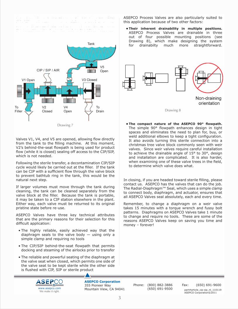
Once the SIP cycle is complete, V2 and V3, controlling CIP/SIP and condensate draining respectively, are closed. Drawing 7 shows the next step in the process, the actual transfer from the tank to the filling machine.
Drawing 7
Valves V1, V4, and V5 are opened, allowing flow directly from the tank to the filling machine. At this moment, V2’s behind-the-seat flowpath is being used for product flow (while it is closed) sealing off access to the CIP/SIP, which is not needed.
Following the sterile transfer, a decontamination CIP/SIP cycle would likely be carried out at the filler. If the tank can be CIP with a sufficient flow through the valve block to prevent bathtub ring in the tank, this would be the natural next step.
If larger volumes must move through the tank during cleaning, the tank can be cleaned separately from the valve block at the filler. Because the tank is portable, it may be taken to a CIP station elsewhere in the plant. Either way, each valve must be returned to its original pristine state before re-use.
ASEPCO Valves have three key technical attributes that are the primary reasons for their selection for this difficult application:
• The highly reliable, easily achieved way that the diaphragm seals to the valve body — using only a simple clamp and requiring no tools
• The CIP/SIP behind-the-seat flowpath that permits docking and steaming of the airlocks prior to transfer
• The reliable and powerful seating of the diaphragm at the valve seat when closed, which permits one side of the valve seat to be kept sterile while the other side is flushed with CIP, SIP or sterile product
ASEPCO Process Valves are also particularly suited to this application because of two other factors:
• Their inherent drainability in multiple positions. ASEPCO Process Valves are drainable in three out of four possible mounting positions (see Drawing 8), which make designing the system for drainabilty much more straightforward.
Drawing 8
• The compact nature of the ASEPCO 90° flowpath. The simple 90° flowpath enhances design in tight spaces and eliminates the need to plan for, buy, or weld additional elbows to keep a tight configuration. It also avoids turning this sterile connection into a christmas tree valve block commonly seen with weir valves. Since weir valves require careful installation to achieve the drainable angle of 15° to 30°, design and installation are complicated. It is also harder, when examining one of these valve trees in the field, to determine which valve does what.
In closing, if you are headed toward sterile filling, please contact us. ASEPCO has the valves that can do the job. The Radial-Diaphragm™ Seal, which uses a simple clamp to connect body, diaphragm, and actuator, ensures that all ASEPCO Valves seal absolutely, each and every time.
Remember, to change a diaphragm on a weir valve takes 15 minutes with a torque wrench and fussy bolt patterns. Diaphragms on ASEPCO Valves take 1 minute to change and require no tools. These are some of the reasons ASEPCO Valves keep on saving you time and money – forever!
3
Related Documents