c hi l l e r 2 Glos s a ry of Te rms Approa ch — T emperature difference between th e leaving fluid an d th e evapo- ratin g ref riger an t AR I Stand ard Conditions — 54°F. water in let; 44°F . wat er ou t; 35°F . ref rigeran t; 0.00025 a dd itive f ou ling factor Flow R at e or veloc ity — S peed at wh ich t h e fluid travel s through th e evaporator. Fouling — Di rt and scale buil d u p th at imp edes heat transfer. One Ton — 12,000 Btu/ h r Pressure Drop — Diff erence in pressure between th e incom ing an d leavin g fluid p ressu res. Ra ng e — T em perature diff erence between t he en tering warm fluid an d th e leaving coo led fluid. Specific Gravity — A measure of the d ensity of a fluid com pared to water. S pecific Hea t — A measure of a flu id’ s abil ity to ab sorb and transport h eat. Superheat — E xtra h eat carried by th e refrigerant after it h as changed from a li qu id int o a gas . Thermal C onductiv ity — A m easure of th e po tent ial rate of heat transfer . Viscosity — A m easure of th e abili ty of a fluid to flow.

Welcome message from author
This document is posted to help you gain knowledge. Please leave a comment to let me know what you think about it! Share it to your friends and learn new things together.
Transcript
8/14/2019 Chill Train
http://slidepdf.com/reader/full/chill-train 1/8
chiller
2
Glossary of Terms
Approach — Tem perature difference between th e leaving fluid an d th e evapo-
ratin g refrigeran t
ARI Standard Conditions — 54°F. water in let; 44°F. wat er out;
35°F. refrigeran t; 0.00025 add itive fou ling factor
Flow Rate or velocity — Speed at wh ich t h e fluid travels through th e evaporator.
Fouling — Dirt and scale build u p th at imp edes heat transfer.
One Ton — 12,000 Btu/ h r
Pressure Drop — Differen ce in pressure between th e incom ing an d leavin g fluid
pressures.
Range — Tem perature difference between t he en tering warm fluid an d th e
leaving coo led fluid.
Specific Gravity — A m easure of the d ensity of a fluid com pared to water.
Specific Heat — A m easure of a flu id’s ability to ab sorb and transport h eat.
Superheat — Extra h eat carried by th e refrigerant after it h as chan ged from a
liqu id int o a gas.
Thermal Conductivity — A m easure of th e po tent ial rate of heat transfer.
Viscosity — A m easure of th e ability of a fluid to flow.
8/14/2019 Chill Train
http://slidepdf.com/reader/full/chill-train 2/8
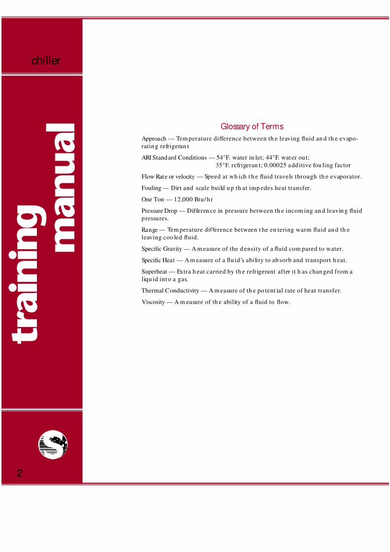
Refrigeration Cycle
Refrigeration is defin ed as a process of removin g heat
from an en closed space or material, an d m ain tainin g
th at space or m aterial at a temperature lower than its
surround ings. Cold an d h ot are relative terms th at are
not generally used when sizing heat transfer equip-
ment. Objects and space being refrigerated become
relatively colder an d colder (or less and less h ot) as
h eat is removed.
Removal of heat lowers temperature and may be
accom plished by th e use of ice, sn ow, ch illed water, or
m echan ical refrigeration. Mechan ical refrigeration
can be defined as an arran gemen t of comp onen ts in a
system for th e purp ose of tran sferring h eat.
Refrigeran t is on e of the key comp on ent s that m akes
m ech an ical refrigeration work. A refrigerant is a
chem ical compou nd that is altern ately com pressed
and con densed int o a liquid, and t hen permitted to
expand into a vapor or gas as it is pumped through
th e mech an ical refrigeration cycle.
This cycle is based on th e ph ysical principle th at a liq-
uid extracts heat from the surrounding area as it
expands (boils) in to a gas.
Refrigeran ts like Am m on ia, R–134A, and R–22, are cir-
culated throu gh th e system by a com pressor, which
increases the pressure and temperature of the
vaporous refrigeran t and pu m ps it into th e conden ser.
In th e con den ser, refrigeran t vapor is cooled by air or
water un til it con den ses in to a liqu id.
The liquid refrigerant then flows to the flow control
device, or expan sion valve, where flow is m etered and
the pressure is reduced, resulting in a reduction in
temp erature. You can u n derstan d th is concept if you
th ink of carbon d ioxide as a nat ural refrigerant. Wh enCO 2 is released from a h igh pressure fire extin guisher
cylin der to at m osph ere, it cools form in g ice crystals,
just like a like a halocarbon refrigerant, but less
ef ficien t.
After the exp an sion valve, refrigeran t flo ws into th e
lower pressure evaporat or, where it bo ils by absorbin g
h eat from t he space bein g cooled, and ch an ges in to a
vapor.
The cycle is completed when the compressor draws
the refrigerant vapor from the evaporator and, once
again, com presses th e gas so tha t th e cycle can con -
tin ue.
Chiller Barr els
Most Stan dard catalog m odels are direct–expan sion .
In d irect expan sion , th e refrigerant evaporates inside
th e tubes as th e medium to be cooled flows through a
baffled course on th e outside of th e tube bun dles. Th e
baffles assure proper m ixin g an d in crease h eat trans-
fer. The other common heat exchange barrels are
flooded chillers and water–cooled con den sers.
refrigeration cycle
3
8/14/2019 Chill Train
http://slidepdf.com/reader/full/chill-train 3/8
There are distinct differences in operation between
direct–expan sion chiller barrels, flood ed chiller bar-
rels, an d w ater–cooled con den sers. All are specializedheat exchangers that operate by removing heat from
on e fluid an d tran sferring it to an oth er. The differen ce
is in th e location of the water, and wh ether th e refrig-
eran t is chan gin g state from a liqu id to a gas, or from
a gas to a liquid.
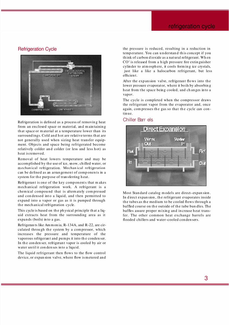
DX Chiller
In t h e pop ular DX (or direct–expan sion ) chiller, heat
is drawn from water wh ich is located outside the tube
as refrigerant boils and evaporates inside. The tube is
finn ed in ternally to increase h eat transfer efficiency.
The direct–expansion ch iller barrel is po pu lar due to
th e therm ostatic expansion valve an d its exception al
ability to cont rol loads.
Direct–expansion chiller barrels are described by the
num ber of refrigeran t circuits, refrigeran t pa sses, an d
th eir capacity.
A sin gle–circuit chiller has on e refrigerant in let and
outlet. A dual–circuit has two refrigerant inlets and
two out lets. Each circuit can be used for two separate
but similar loads. There’s also a qu ad–circuit, design ed
for four separate loads. Direct–expan sion ch iller bar-
rels are also distinguish ed by th e n um ber of tim es that
refrigeran t passes back and forth with in th e len gth of
th e vessel. In a sin gle–pass un it, liquid refrigeran t
ent ers at on e end, passes straigh t th rough an d leaves
as a vapor in a single pass. In a dual–pass m odel, the
liquid refrigerant must go down and back the length
of th e ch iller before it exits as vapor. Refrigerant ent ersand exits at the same end of the chiller when the
n um ber of passes is even, and at opp osite end s wh en
th e nu mb er of passes is odd.
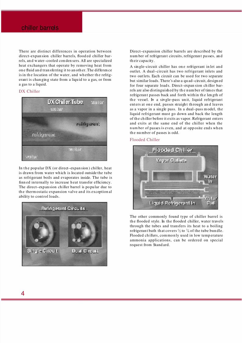
Flooded Chiller
The other commonly found type of chiller barrel is
th e flooded style. In th e flooded chiller, water travels
through the tubes and transfers its heat to a boiling
refrigeran t bath th at covers 1 ⁄ 2 to 3 ⁄ 4 of the tube bun dle.
Flooded ch illers, com mo n ly used in low temp erature
ammonia applications, can be ordered on specialrequest from Stand ard.
chiller barrels
4
8/14/2019 Chill Train
http://slidepdf.com/reader/full/chill-train 4/8
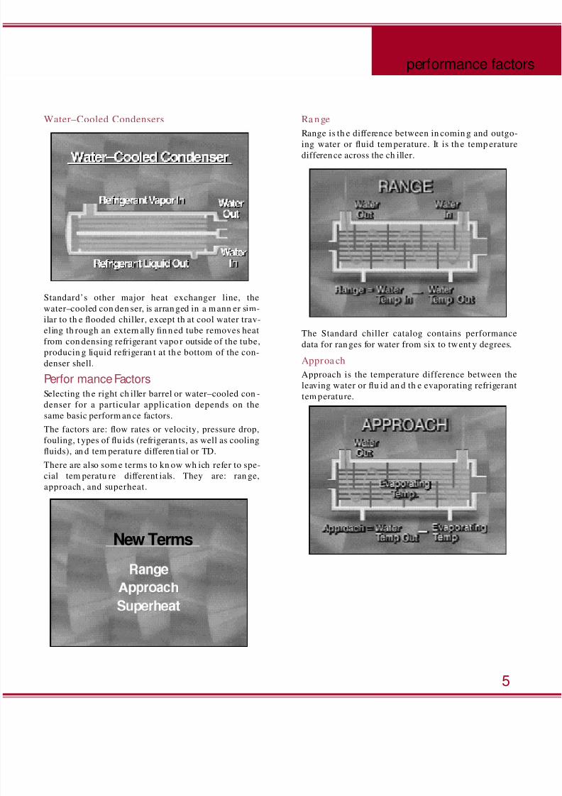
Water–Cooled Condensers
Standard’s other major heat exchanger line, the
water–cooled con den ser, is arran ged in a m ann er sim-
ilar to th e flooded chiller, except th at cool water trav-
eling th rough an extern ally fin n ed tube removes heat
from con densing refrigerant vapo r outside of the tube,
producin g liquid refrigeran t at th e bottom of the con-
denser shell.
Perfor mance FactorsSelecting th e right ch iller barrel or water–cooled con -
denser for a particular application depends on the
same basic perform an ce factors.The factors are: flow rates or velocity, pressure drop,
fouling, t ypes of flu ids (refrigeran ts, as well as cooling
fluids), an d tem peratu re differen tial or TD.
There are also som e terms to kn ow wh ich refer to spe-
cial tem peratu re different ials. They are: ran ge,
approach , and superheat.
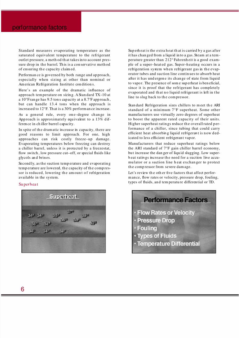
Ra nge
Range is th e difference between in comin g and outgo-
ing water or fluid tem perature. It is th e temp erature
difference across the ch iller.
The Standard chiller catalog contains performance
data for ran ges for water from six to twent y degrees.
Approa ch
Approach is the temperature difference between the
leaving water or flu id an d th e evaporating refrigerant
tem perature.
5
performance factor
New Terms
8/14/2019 Chill Train
http://slidepdf.com/reader/full/chill-train 5/8
Standard measures evaporating temperature as the
saturated equivalent temperature to the refrigerant
outlet pressure, a meth od th at takes in to account pres-sure drop in th e barrel. Th is is a con servative meth od
of ensuring th e capacity claim ed.
Performan ce is governed by both range and ap proach,
especially when sizing at other than nominal or
Am erican Refrigeration Institut e con dition s.
Here’s an example of the dramatic influence of
approach tem perature on sizin g. A Stan dard TX–10 at
a 10°F ran ge has 9.5 ton s cap acity at a 8.7°F app roach ,
but can handle 13.4 tons when the approach is
increased to 12°F. Th at is a 30% perform an ce increase.
As a gen eral rule, every on e–degree ch an ge in
App roach is approximat ely equ ivalent to a 13% d if-feren ce in ch iller barrel capacity.
In spite of th e dram atic in crease in capacity, th ere are
good reasons to limit approach. For one, high
approaches can risk costly freeze–up damage.
Evaporating temperatures below freezing can destroy
a chiller barrel, unless it is protected by a freezestat,
flow switch , low pressure cut–off, or special fluids like
glycols an d brin es.
Second ly, as th e suction temp erature and evaporatin g
temp erature are lowered, th e capacity of th e comp res-
sor is reduced, lowering th e am oun t o f refrigeration
available in the system.
Superhea t
Sup erh eat is the extra h eat th at is carried b y a gas after
it has chan ged from a liqu id in to a gas. Steam at a tem -
perature greater than 212° Fah renh eit is a good exam-ple of a super–heat ed gas. Super–h eating occurs in a
refrigeration system wh en refrigerant gas in th e evap-
orator tubes and suction line contin ues to absorb heat
after it h as und ergon e its ch an ge of state from liquid
to vapor. The p resence of som e sup erheat is ben eficial,
since it is proof that the refrigerant has completely
evaporated and th at n o liquid refrigerant is left in t he
line to slug back to th e com pressor.
Stan dard Refrigeration sizes chillers to m eet th e ARI
standard of a minimum 7°F superheat. Some other
manufacturers use virtually zero degrees of superheat
to boost the apparent rated capacity of their units.Higher superheat ratin gs reduce th e overall rated p er-
formance of a chiller, since tubing that could carry
efficient heat absorbin g liquid refrigeran t is n ow d ed-
icated to less efficient refrigeran t vap or.
Manufacturers that reduce superheat ratings below
the ARI standard of 7°F gain chiller barrel economy,
bu t increase the dan ger of liqu id slugging. Low super-
h eat ratin gs increase th e need for a suction lin e accu-
mu lator or a suction line h eat exchan ger to p rotect
th e comp ressor from severe dam age.
Let’s review th e oth er five facto rs that affect perfor-
m ance, flow rates or velocity, pressure drop, fouling,types of fluids, an d tem peratu re differen tial or TD.
performance factors
6
Performance Factors
8/14/2019 Chill Train
http://slidepdf.com/reader/full/chill-train 6/8
Flow Ra tes
Water flow rates (velocity) in a ch iller barrel must be
h eld to 41 ⁄ 2 feet per secon d to avoid impin gemen t cor-
rosion dam age. All Stan dard selection recom m enda -
tions in our literature are un der 41 ⁄ 2 feet p er second .
Pressu re Drop
Pressure drop is th e d ifference between th e ent ering
and leavin g water pressure. Th e pum p capacity mu st
be great enough to overcome the combined pressure
drop across the chiller barrel and piping. Choose
anoth er model un less you’re sure that your pum p h as
th e capacity.
Fou ling
Fouling is scale or foreign material build–up thatreduces heat transfer. Most packaged chillers for
air–conditioning have sealed loop systems. There is
little opp ortun ity for fouling with in th e chiller barrel,
because the cooling flu id is sealed from external envi-
ron m ent al factors. Process ch illers in p lastics m oldin g
and other industrial applications often have open
chilled wat er tanks or op en processes wh ere the wat er
can foul badly an d ad ded capacity m ust be available
to com pen sate for th e fouling.
Stan dard rat es its chiller barrels with an add itive fou l-
ing factor of 0.00025 (0.0005 tot al).
Types of Fluids
Fluid types and refrigerants can vary, depending on
th e application . Th e most comm on flu ids are water,
eth ylene glycol, prop ylene glycol, and brine solut ions.
Fluids are the gasses or liquids that exchange heat in
h eat transfer. Fluids oth er than water can be con sider-
ably less efficien t an d h ave a substantial effect on th e
sizing of a ch iller. Special ch iller designs m ay be
required if glycols are used to preven t freeze dam age
in low tem perature application s.
The refrigerant itself must be taken into considera-
tion. Standard’s cataloged capacity data is based on
R–22. However, information for other refrigerants,
including R–502 an d am m on ia, are readily available
from t h e factory or sales represen tative.
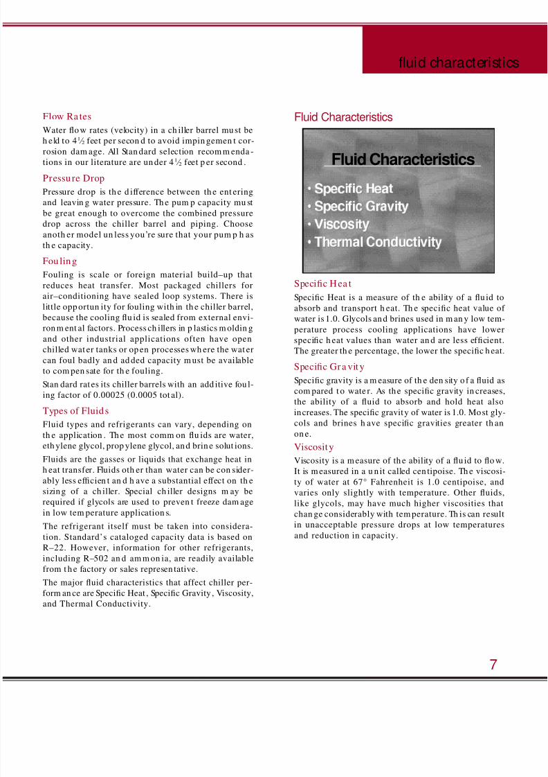
The major fluid characteristics that affect chiller per-
form an ce are Specific Heat , Specific Gravity , Viscosity,
and Thermal Conductivity.
Fluid Characteristics
Specific Hea t
Specific Heat is a measure of th e ability of a flu id to
absorb and transport h eat. Th e specific heat value of
water is 1.0. Glycols and brines used in m an y low tem-
perature process cooling applications have lower
specific h eat values than water an d are less efficient.
The greater th e percentage, the lower the specific h eat.
Specific Gra vity
Specific gravity is a m easure of th e den sity o f a fluid as
com pared t o wate r. As the specific gravity in creases,
the ability of a fluid to absorb and hold heat also
increases. The specific gravity of water is 1.0. Most gly-
cols and brines h ave specific gravities greater th an
on e.
Viscosity
Viscosity is a m easure of th e ability of a flu id to flo w.
It is m easured in a u n it called cen tipoise. Th e viscosi-
ty of water at 67° Fahrenheit is 1.0 centipoise, and
varies only slightly with temperature. Other fluids,
like glycols, may have much higher viscosities that
chan ge considerably with tem perature. Th is can result
in unacceptable pressure drops at low temperatures
and reduction in capacity.
7
fluid characteristic
Fluid Characteristics
8/14/2019 Chill Train
http://slidepdf.com/reader/full/chill-train 7/8
Therm a l Cond uctivity
Therm al Con ductivity is th e fourth fluid factor tha t
can affect performance. It is related to the potential
rate of heat transfer across a temperature differential
for a fluid. Th e th ermal condu ctivity of pure water at
44° Fahren heit is 0.338, while a 30% solution o f eth y-
lene glycol at th e sam e tem perature is 0.256.
It is always best to con sult with your Stan dard sales
representative for fluids other than water. Standard
h as complete data on eth ylene an d propylene glycols,
as well as sod ium an d calcium brin es. If you are deal-
ing with a more exotic fluid, try to have the specific
h eat, specific gravity, viscosity, an d th erm al con du c-
tivity ready when you call Stand ard for help with your
selection .
Ma teria ls
Remem ber that m ost stock ch iller barrels contain cop-
per tu bes; th erefore, am m on ia refrigeran t or ch loride
brines cannot be used. Cupronickel construction
should be specified for chloride brines. Carbon or
stain less steel shou ld be specified for am m on ia appli-
cations. Be sure to consult the factory for a special
selection if you h ave any q uestion s.
Sizing
Sizing by Nominal Ton sThere are th ree basic selection m etho ds you can use to
size a chiller. The first an d easiest is to size by nom inal
system s ton s. Th e second m etho d is to use com pressor
capacity. The th ird and recomm end ed m etho d is siz-
ing by ran ge, flow and approach.
Sizing by no m inal ton s is don e according to ARI stan -
dards. Chillers can be selected on a n om inal system
ton s basis, as sh own in th e catalog, or reflected in th e
m od el n ame. For example, an TX–50–2 is a nom inal
50 ton dual–circuit barrel.
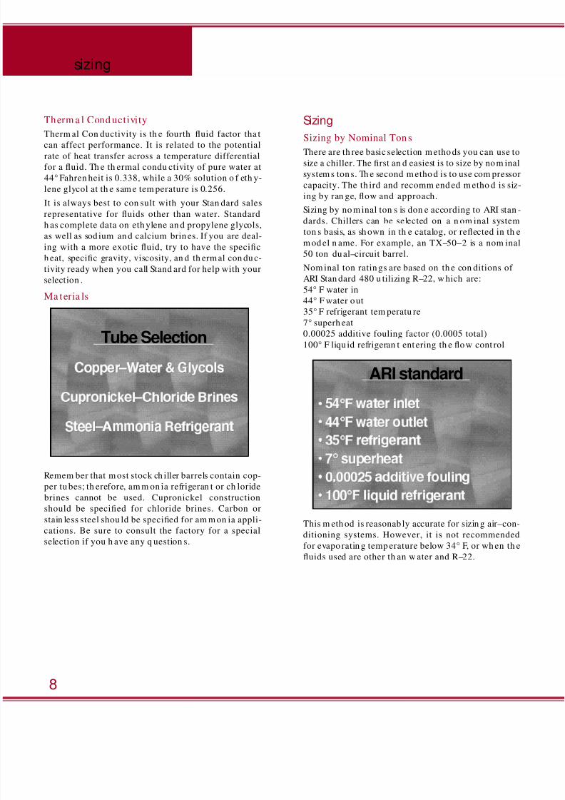
Nom inal ton ratin gs are based on th e con ditions of
ARI Stan dard 480 u tilizing R–22, w hich are:54° F water in
44° F water out
35° F refrigerant tem peratu re
7° superh eat
0.00025 additive fouling factor (0.0005 total)
100° F liqu id refrigeran t ent ering th e flow cont rol
This m eth od is reasonab ly accurate for sizin g air–con-
ditioning systems. However, it is not recommended
for evapo ratin g temp erature below 34° F, or wh en th e
fluids used are other th an w ater and R–22.
sizing
8
ARI standard
Tube Selection
8/14/2019 Chill Train
http://slidepdf.com/reader/full/chill-train 8/8
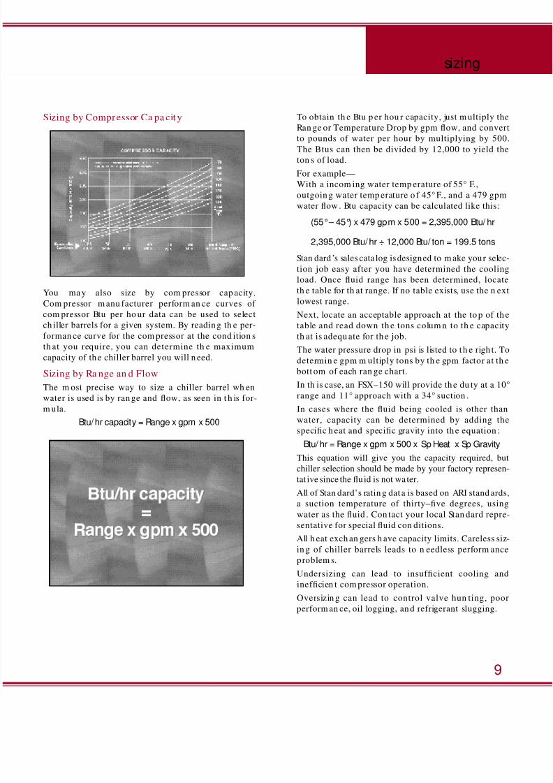
Sizing by Compressor Ca pa cit y
You ma y also size by com pressor cap acity.
Com pressor m anu facturer perform an ce curves of
com pressor Btu per ho ur data can be used to select
ch iller barrels for a given system. By reading th e per-
forman ce curve for the com pressor at the cond ition s
th at you require, you can determine th e maximum
capacity of the chiller barrel you will n eed.
Sizing by Ra nge an d Flow
The m ost precise way to size a chiller barrel wh en
water is used is by ran ge and flow, as seen in t h is for-
m ula.Btu/ hr capacity = Range x gpm x 500
To obtain th e Btu p er hou r capacity, just m ultiply the
Ran ge or Temperature Drop by gpm flow, and convert
to pounds of water per hour by multiplying by 500.The Btus can then be divided by 12,000 to yield the
ton s of load.
For example—
With a incom ing water temp erature of 55° F.,
outgoin g water temp erature o f 45° F., and a 479 gpm
water flow. Btu capacity can be calculated like this:
(55°– 45°) x 479 gpm x 500 = 2,395,000 Btu/ hr
2,395,000 Btu/ hr ÷ 12,000 Btu/ ton = 199.5 tons
Stan dard ’s sales cata log is designed to m ake your selec-
tion job easy after you have determined the cooling
load. Once fluid range has been determined, locate
th e table for th at range. If no table exists, use the n ext
lowest range.
Next, locate an acceptable approach at the to p of th e
table and read down th e tons colum n to th e capacity
th at is adequ ate for th e job.
The water pressure drop in psi is listed to t h e righ t. To
determin e gpm m ultiply tons by th e gpm factor at th e
bott om of each ran ge chart.
In th is case, an FSX–150 will provide th e du ty at a 10°
range and 11° approach with a 34° suction .
In cases where the fluid being cooled is other thanwater, capacity can be determined by adding the
specific h eat and specific gravity into th e equation :
Btu/ hr = Range x gpm x 500 x Sp Heat x Sp Gravity
This equation will give you the capacity required, but
chiller selection should be made by your factory represen-
tat ive since the fluid is not water.
All of Stan dard’s ratin g dat a is based on ARI stand ards,
a suction temperature of thirty–five degrees, using
water as the fluid . Con tact your local Stan dard repre-
sentative for special fluid con ditions.
All h eat exch an gers h ave capacity limits. Careless siz-
in g of chiller barrels leads to n eedless perform anceproblem s.
Undersizing can lead to insufficient cooling and
inefficien t com pressor operation.
Oversizin g can lead to control valve hun ting, poor
perform an ce, oil logging, and refrigerant slugging.
9
sizing
Related Documents