Chevron Corporation 600-1 March 1990 600 Fabrication and In-Shop Inspection Abstract This section discusses the fabrication of pressure vessels, including plate materials, methods of forming the shell and head components and nozzles, fabrication welds, welding processes and procedures, and in-shop inspection. The section on nozzles includes both integrally reinforced and “built-up” nozzles; and the section on fabri- cation welds discusses longitudinal, nozzle, and girth welds, skirt attachment weld, and postweld heat treatment (PWHT). Also included are fit-up tolerances and requirements for nondestructive examination (NDE). Numerous welding processes for the fabrication of pressure vessels are described and evaluated, along with the following: consumables, preheat and interpass temperature control, procedures and methods for PWHT, and alternatives to stress relief heat treatment. The section on welding procedure qualification contains a step-by-step welding procedure review and guidance on welder performance qualifi- cation. Additional information about welding can be obtained from the Welding Manual. In-shop inspection includes defined inspection visits and guidelines for choosing the appropriate degree of inspection for pressure vessels. Contents Page 610 Overview 600-3 620 Plate Materials 600-3 630 Forming of Shell and Head Components 600-4 631 Shell Ring Courses 632 Heads 640 Nozzles 600-8 641 Integrally Reinforced Nozzles 642 “Built-Up” Nozzles 650 Fabrication Welds 600-11

CHEVRON Pressure Vessel - Fabrication and in Shop Inspection
Sep 30, 2014
Welcome message from author
This document is posted to help you gain knowledge. Please leave a comment to let me know what you think about it! Share it to your friends and learn new things together.
Transcript

ri-eld,
ed
ess ualifi-
g the
600 Fabrication and In-Shop Inspection
AbstractThis section discusses the fabrication of pressure vessels, including plate materials, methods of forming the shell and head components and nozzles, fabrication welds, welding processes and procedures, and in-shop inspection. The section on nozzles includes both integrally reinforced and “built-up” nozzles; and the section on fabcation welds discusses longitudinal, nozzle, and girth welds, skirt attachment wand postweld heat treatment (PWHT). Also included are fit-up tolerances and requirements for nondestructive examination (NDE).
Numerous welding processes for the fabrication of pressure vessels are describand evaluated, along with the following: consumables, preheat and interpass temperature control, procedures and methods for PWHT, and alternatives to strrelief heat treatment. The section on welding procedure qualification contains astep-by-step welding procedure review and guidance on welder performance qcation. Additional information about welding can be obtained from the Welding Manual.
In-shop inspection includes defined inspection visits and guidelines for choosinappropriate degree of inspection for pressure vessels.
Contents Page
610 Overview 600-3
620 Plate Materials 600-3
630 Forming of Shell and Head Components 600-4
631 Shell Ring Courses
632 Heads
640 Nozzles 600-8
641 Integrally Reinforced Nozzles
642 “Built-Up” Nozzles
650 Fabrication Welds 600-11
Chevron Corporation 600-1 March 1990
600 Fabrication and In-Shop Inspection Pressure Vessel Manual
651 Longitudinal Welds
652 Nozzle Welds
653 Girth Welds
654 Skirt Attachment Weld
655 Postweld Heat Treatment
660 Welding Processes and Procedures 600-18
661 Welding Processes
662 Consumables
663 Preheat and Interpass Temperature Control
664 Postweld Heat Treatment
665 Welding Procedure Qualification
666 Welding Procedure Review
667 Company Qualified Welding Procedures
668 Welder Performance Qualification
670 In-Shop Inspection 600-53
671 General Comments
672 Degree of Inspection
673 Inspection Tasks
March 1990 600-2 Chevron Corporation
Pressure Vessel Manual 600 Fabrication and In-Shop Inspection
610 OverviewThe fabrication of a pressure vessel is a demanding technical effort. A thorough knowledge of materials, welding, and NDE technologies must be combined with a high level of skilled workmanship to manufacture a vessel with the high quality that is required to provide many years of reliable service in the often severe operating conditions encountered.
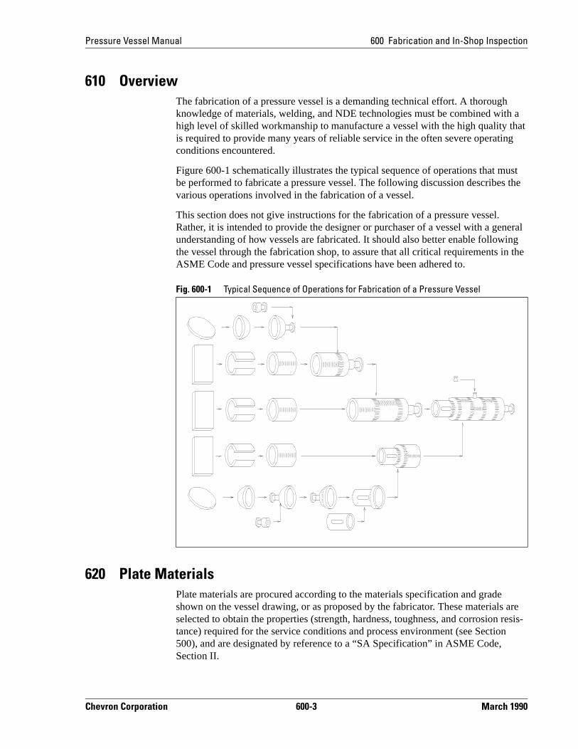
Figure 600-1 schematically illustrates the typical sequence of operations that must be performed to fabricate a pressure vessel. The following discussion describes the various operations involved in the fabrication of a vessel.
This section does not give instructions for the fabrication of a pressure vessel. Rather, it is intended to provide the designer or purchaser of a vessel with a general understanding of how vessels are fabricated. It should also better enable following the vessel through the fabrication shop, to assure that all critical requirements in the ASME Code and pressure vessel specifications have been adhered to.
620 Plate MaterialsPlate materials are procured according to the materials specification and grade shown on the vessel drawing, or as proposed by the fabricator. These materials are selected to obtain the properties (strength, hardness, toughness, and corrosion resis-tance) required for the service conditions and process environment (see Section 500), and are designated by reference to a “SA Specification” in ASME Code, Section II.
Fig. 600-1 Typical Sequence of Operations for Fabrication of a Pressure Vessel
Chevron Corporation 600-3 March 1990
600 Fabrication and In-Shop Inspection Pressure Vessel Manual
e-,
eci-to erial ion
essel lter
e the ecifi-ts
spec-
n
e,
ead ti-e ce)
fabri-on his en ess
The model specifications for pressure vessels (PVM-MS-4748, PVM-MS-4749, and PVM-MS-4750) impose a few requirements, such as CV-impact testing, to prevent brittle fracture that exceed ASME Code requirements. Furthermore, these specifica-tions require the fabricator to verify that the required materials properties will be obtained by the materials in a condition that is representative of the completed vessel.
The fabricator orders the plate materials using a purchase specification that is a part of the Quality Control System that the fabricator must establish to obtain an ASME Code Certificate of Authorization for use of the “U” or “U2” symbols. These matrials must comply with the requirements of the SA Specification in ASME CodeSection II, and the supplier must provide the fabricator with a “Materials Test Report” for each lot of material certifying that all of these requirements in the spfication have been met. The authorized inspector (see Section 200) is required examine these test reports to verify that they correctly represent the lots of matdelivered to the fabricator and that all of the requirements of ASME Code, SectII, have been met.
The fabricator should incorporate any additional requirements in the pressure vspecification into his materials purchase specification. The fabricator must alsorecognize that forming, welding, and postweld heat treatment can significantly athe properties of the material after it is received from the supplier. Therefore, thfabricator must consider the changes in materials properties that will result fromfabrication procedures that will be used, and prepare his materials purchase spcation to allow for these changes. The fabricator may perform supplemental tesrequired to confirm that the material properties specified in the pressure vesselification will be obtained in the completed vessel, by simulating the anticipated thermal history (i.e., heat treatment, hot forming, reheat treatment, welding, andpostweld heat treatment, etc.) with test coupons. Alternatively, the fabricator cahave the materials supplier perform these tests, to be certain that the material supplied will meet the property requirements for the completed vessel. The Codhowever, does not require this supplemental testing in all cases. The company inspector should review these test data to determine that the materials propertyrequirements in the pressure vessel specification have been met.
The deformation of plate material associated with the forming of the shell and hcomponents of a vessel can reduce the thickness of the plate. This must be esmated by the fabricator, based upon his experience; and plate materials that arsomewhat thicker than the minimum required thickness (plus corrosion allowanof the formed shell component must be procured from the supplier.
630 Forming of Shell and Head ComponentsThe shell and head components of pressure vessels are usually formed by the cator from plate materials that are procured from materials suppliers (see Secti620). Forming causes deformation that can reduce the thickness of the plate. Treduction in plate thickness by forming must be considered by the fabricator whthe plate material is procured, to make certain that the minimum required thicknplus corrosion allowance is obtained.
March 1990 600-4 Chevron Corporation
Pressure Vessel Manual 600 Fabrication and In-Shop Inspection
first
lates h
am-um-
his t by ngles
d to te-
pe eter ap) to ion tor
r be
r-
631 Shell Ring CoursesCylindrical ring courses for pressure vessels are most frequently fabricated by a process referred to as “rolling and welding.” Plate with the required thickness iscut to the size required for the diameter of the vessel and the length of the ring course. Relatively thin plates can be mechanically cut by shearing, but thicker pare generally cut by oxyfuel gas or plasma-arc cutting. Whenever possible, eacring course is made from one piece of plate cut to a length that is equal to the circumference of the vessel, thus requiring only one longitudinal weld. Large dieter, or thick wall vessels may necessitate two or more plates to obtain the circference, and consequently two or more longitudinal welds.
Weld bevels can be machined on the plate edges after the plate is cut to size. Tmachining must remove all shear damaged material from the edges of plate cushearing. Oxyfuel gas or plasma-arc cutting is also used to obtain the correct afor the weld bevels on the edges at the same time that the plate is cut to size. Oxyfuel gas or plasma-arc cutting can therefore significantly reduce the time ancost of machining, but some finish machining or grinding is sometimes requiredobtain an acceptable surface for welding and to remove thermally damaged marial.
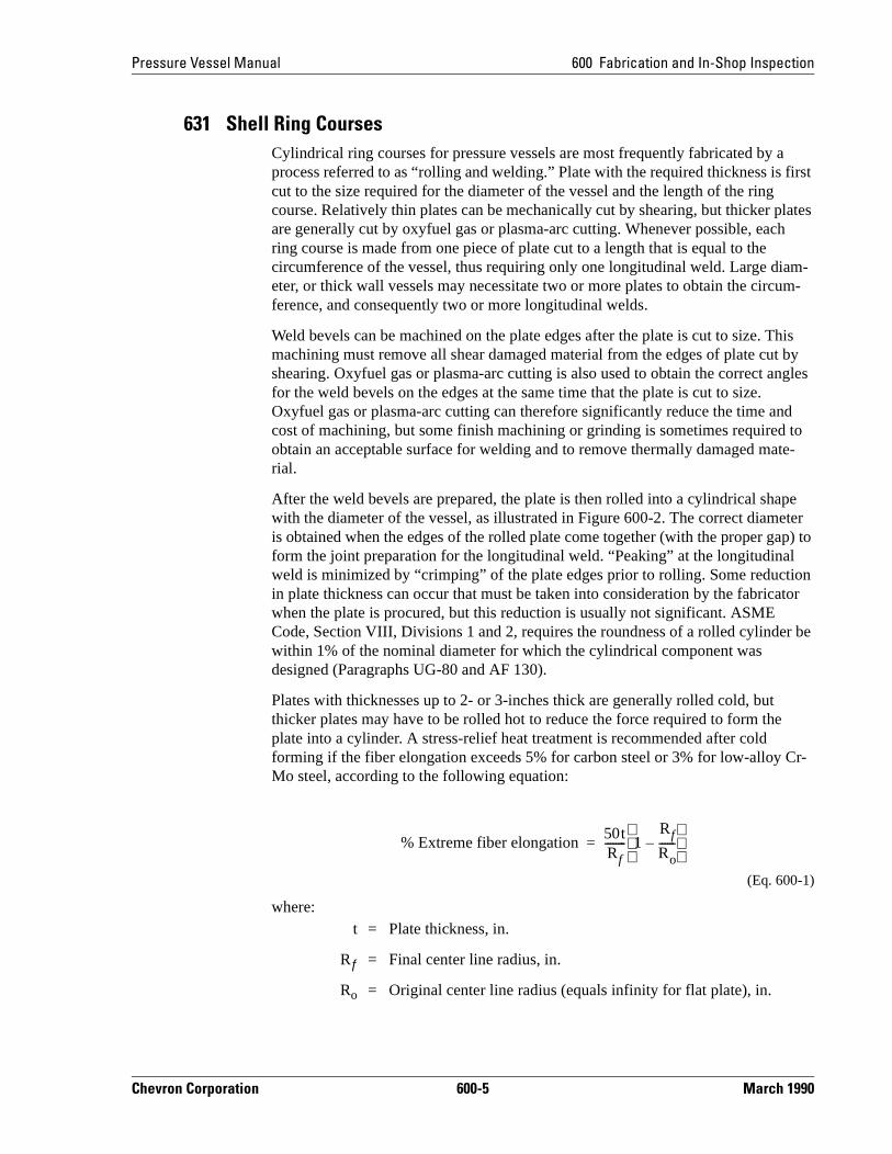
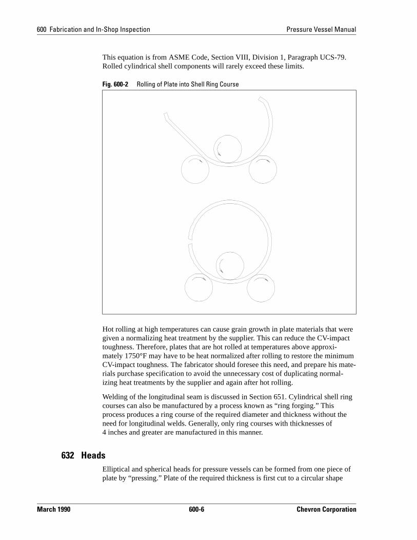
After the weld bevels are prepared, the plate is then rolled into a cylindrical shawith the diameter of the vessel, as illustrated in Figure 600-2. The correct diamis obtained when the edges of the rolled plate come together (with the proper gform the joint preparation for the longitudinal weld. “Peaking” at the longitudinalweld is minimized by “crimping” of the plate edges prior to rolling. Some reductin plate thickness can occur that must be taken into consideration by the fabricawhen the plate is procured, but this reduction is usually not significant. ASME Code, Section VIII, Divisions 1 and 2, requires the roundness of a rolled cylindewithin 1% of the nominal diameter for which the cylindrical component was designed (Paragraphs UG-80 and AF 130).
Plates with thicknesses up to 2- or 3-inches thick are generally rolled cold, but thicker plates may have to be rolled hot to reduce the force required to form theplate into a cylinder. A stress-relief heat treatment is recommended after cold forming if the fiber elongation exceeds 5% for carbon steel or 3% for low-alloy CMo steel, according to the following equation:
(Eq. 600-1)
where:t = Plate thickness, in.
Rƒ = Final center line radius, in.
Ro = Original center line radius (equals infinity for flat plate), in.
% Extreme fiber elongation50tRf-------- 1
Rf
Ro------–
=
Chevron Corporation 600-5 March 1990
600 Fabrication and In-Shop Inspection Pressure Vessel Manual
um mate-l-
ing
the
e of
This equation is from ASME Code, Section VIII, Division 1, Paragraph UCS-79. Rolled cylindrical shell components will rarely exceed these limits.
Hot rolling at high temperatures can cause grain growth in plate materials that were given a normalizing heat treatment by the supplier. This can reduce the CV-impact toughness. Therefore, plates that are hot rolled at temperatures above approxi-mately 1750°F may have to be heat normalized after rolling to restore the minimCV-impact toughness. The fabricator should foresee this need, and prepare hisrials purchase specification to avoid the unnecessary cost of duplicating normaizing heat treatments by the supplier and again after hot rolling.
Welding of the longitudinal seam is discussed in Section 651. Cylindrical shell rcourses can also be manufactured by a process known as “ring forging.” This process produces a ring course of the required diameter and thickness without need for longitudinal welds. Generally, only ring courses with thicknesses of 4 inches and greater are manufactured in this manner.
632 HeadsElliptical and spherical heads for pressure vessels can be formed from one piecplate by “pressing.” Plate of the required thickness is first cut to a circular shape
Fig. 600-2 Rolling of Plate into Shell Ring Course
March 1990 600-6 Chevron Corporation
Pressure Vessel Manual 600 Fabrication and In-Shop Inspection
e by
d te kle
sid-
ads e
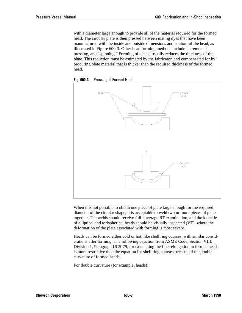
with a diameter large enough to provide all of the material required for the formed head. The circular plate is then pressed between mating dyes that have been manufactured with the inside and outside dimensions and contour of the head, as illustrated in Figure 600-3. Other head forming methods include incremental pressing, and “spinning.” Forming of a head usually reduces the thickness of thplate. This reduction must be estimated by the fabricator, and compensated forprocuring plate material that is thicker than the required thickness of the formedhead.
When it is not possible to obtain one piece of plate large enough for the requirediameter of the circular shape, it is acceptable to weld two or more pieces of platogether. The welds should receive full-coverage RT examination, and the knucof elliptical and torispherical heads should be visually inspected (VT), where thedeformation of the plate associated with forming is most severe.
Heads can be formed either cold or hot, like shell ring courses, with similar conerations after forming. The following equation from ASME Code, Section VIII, Division 1, Paragraph UCS-79, for calculating the fiber elongation in formed heis more restrictive than the equation for shell ring courses because of the doublcurvature of formed heads.
For double curvature (for example, heads):
Fig. 600-3 Pressing of Formed Head
Chevron Corporation 600-7 March 1990
600 Fabrication and In-Shop Inspection Pressure Vessel Manual
to
ches r.
e more e
he
ase is -
e
s.
ri-in de
roce-s that als tor or will
(Eq. 600-2)
Formed heads may therefore require a stress-relief heat treatment when cylindrical components in the same vessel do not. When postweld heat treatment is required by the ASME Code or the purchase specification, this heat treatment can also serve the function of the stress-relief necessitated by the fiber elongation. In fact, it is prefer-able to perform the stress-relief after the cold formed heads are welded to the cylin-drical shell components, because some distortion can accompany stress-relief that could result in poor fit-up for girth welding.
Formed heads can be purchased by the fabricator from a vendor, but they can also be formed from plate material by the fabricator. Heads can also be fabricated from several “pie-shaped” pieces of plate, called gore sections. Each piece is formedthe required contour of the head, and they are then welded together.
640 Nozzles
641 Integrally Reinforced NozzlesIntegrally reinforced nozzles are recommended for shell components that are 2-inthick and greater, or that have maximum design temperatures of 650°F and higheThese nozzles can be nondestructively examined to the higher quality standardsdesired for service at high pressures and high temperatures, and they can also breadily nondestructively examined for flaws that might develop during service (seSection 700).
The fabricator must procure these forgings from a forging vendor according to tmaterials specification and grade shown on the vessel drawing, which again is designated by a “SA Specification” in ASME Code, Section II.
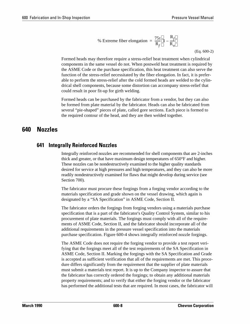
The fabricator orders the forgings from forging vendors using a materials purchspecification that is a part of the fabricator's Quality Control System, similar to hprocurement of plate materials. The forgings must comply with all of the requirements of ASME Code, Section II, and the fabricator should incorporate all of thadditional requirements in the pressure vessel specification into the materials purchase specification. Figure 600-4 shows integrally reinforced nozzle forging
The ASME Code does not require the forging vendor to provide a test report vefying that the forgings meet all of the test requirements of the SA Specification ASME Code, Section II. Marking the forgings with the SA Specification and Grais accepted as sufficient verification that all of the requirements are met. This pdure differs significantly from the requirement that the supplier of plate materialmust submit a materials test report. It is up to the Company inspector to assurethe fabricator has correctly ordered the forgings; to obtain any additional materiproperty requirements; and to verify that either the forging vendor or the fabricahas performed the additional tests that are required. In most cases, the fabricat
% Extreme fiber elongation75tRf-------- 1
Rf
Ro------–
=
March 1990 600-8 Chevron Corporation
Pressure Vessel Manual 600 Fabrication and In-Shop Inspection
require the forging vendor to provide materials test reports for review by the Company inspector.
The strength and CV-impact toughness properties of forgings can be highly direc-tional, depending on the direction of metal flow. All forgings should be forged as close as practicable to finished size and shape to develop metal flow in a direction most favorably oriented for resisting the stresses encountered in service. This requirement is in the traditional concept of a forging, but some vendors and fabrica-tors overlook this. The metal flow in forgings that are forged close to the finished shape follows the surface contour, as shown in Figure 600-4a, which is usually the most favorable orientation for the stresses encountered in service.
Some forging vendors produce a forged billet and then machine the billet to the finished shape. With this type of forging process, the metal flow does not follow the surface contours, as shown in Figure 600-4b. Consequently, the metal flow in a machined billet will not be favorably oriented for the bending stresses that can develop in the flange of a nozzle forging.
Fig. 600-4 Integrally Reinforced Nozzle Forgings
Chevron Corporation 600-9 March 1990

600 Fabrication and In-Shop Inspection Pressure Vessel Manual
They
ate-ME n
ifi-ey
sel -
642 “Built-Up” NozzlesNozzles for pressure vessels can also be fabricated from standard size pipe and ANSI piping flanges, or from rolled-and-welded plate with plate flanges, as shown in Figure 600-5. These types of nozzles are satisfactory for shell components less than 2-inches thick and when maximum design temperatures are below 650°F.are usually less expensive to fabricate than integrally forged nozzles.
Pipe and Pipe Flange NozzlesThe fabricator must procure the pipe and forged pipe flanges according to the mrials specified in the vessel drawing as designated by “SA Specifications” in ASCode, Section II, and the fabricator must incorporate any additional specificatiorequirements into the materials purchase specification. The pipe flanges must comply with ANSI B16.5. Marking the pipe and pipe flanges with their SA Speccation and Grade is accepted by the ASME Code as sufficient indication that thcomply with all of the requirements of ASME Code, Section II. Most fabricatorswill maintain traceability to material test reports for alloy pipe. The company inspector must verify that all of the additional tests required by the pressure vesspecification have been performed either by the materials suppliers or the fabricator, by review of certified test reports.
Fig. 600-5 “Built-Up” Nozzles
March 1990 600-10 Chevron Corporation
Pressure Vessel Manual 600 Fabrication and In-Shop Inspection
It is important to note that full penetration welds are recommended in the pressure vessel specifications (PVM-MS-4749 and PVM-MS-4750), although the ASME Code permits partial penetration welds. Partial penetration welds are undesirable because they can act as crack initiators at locations with potentially high complex stresses and bending moments. Furthermore, they are more difficult to examine nondestructively for flaws during fabrication or for flaws that might develop during service. The Company inspector should verify that the fabricator is complying with the requirement for making only full penetration welds.
Rolled and Welded Nozzles with Plate FlangesNozzles built-up from rolled and welded plate with plate flanges will generally be required for larger diameter openings, when standard pipe sizes and ANSI B16.5 pipe flanges are not available.
The plate for rolled and welded nozzles with plate flanges must be procured like the plate for cylindrical shell components (see Section 620). Furthermore, fabrication of the cylindrical nozzle barrel is similar to the fabrication of a cylindrical shell component. It is important to note that only full penetration welds are permitted by the pressure vessel model specifications for this type of nozzle, as for nozzles built-up from pipe and pipe flanges.
650 Fabrication WeldsThis section discusses welding, with focus on the fabrication process. Section 660 covers welding processes, weld materials, pre- and postweld heat treatment, weld-procedure qualification, and review of welding procedures. More specific informa-tion is covered in the Welding Manual.
651 Longitudinal WeldsLongitudinal welds (referred to as Category A by the ASME Code) in the cylin-drical shell are the weld joints with the highest design stresses in the entire vessel. Full penetration welds that are welded from both sides of the shell (referred to as Type 1 in the ASME Code) provide the highest quality weld joint. The model speci-fications recommend this type of weld.
WeldingThe plate materials for cylindrical shell components are rolled (formed) into cylin-drical shapes with the required diameters, and the bevels (joint preparations) for the longitudinal welds are made as described in Section 620. The pressure vessel Speci-fication PVM-MS-4749 recommends MT examination of weld bevels for shell components 2-inches thick and greater, to prevent flaws in the plate from compro-mising the integrity of the weld joint. ASME Code, Section VIII, Divisions 1 and 2, requires misalignment of the mating joint preparations for longitudinal welds to be within the following limits (Paragraphs UW-33 and AF-142):
Section Thickness (t), in. Misalignment Tolerancesof Mating Joint
Chevron Corporation 600-11 March 1990
600 Fabrication and In-Shop Inspection Pressure Vessel Manual
It is usually necessary to use clips (temporary attachments) welded to the shell to obtain alignment within these limits, and to maintain the same tolerances during welding. It is advisable for the Company inspector to observe the fit-up of some welds prior to welding to make certain that the fabricator is practicing the workman-ship required to obtain alignment within these tolerances.
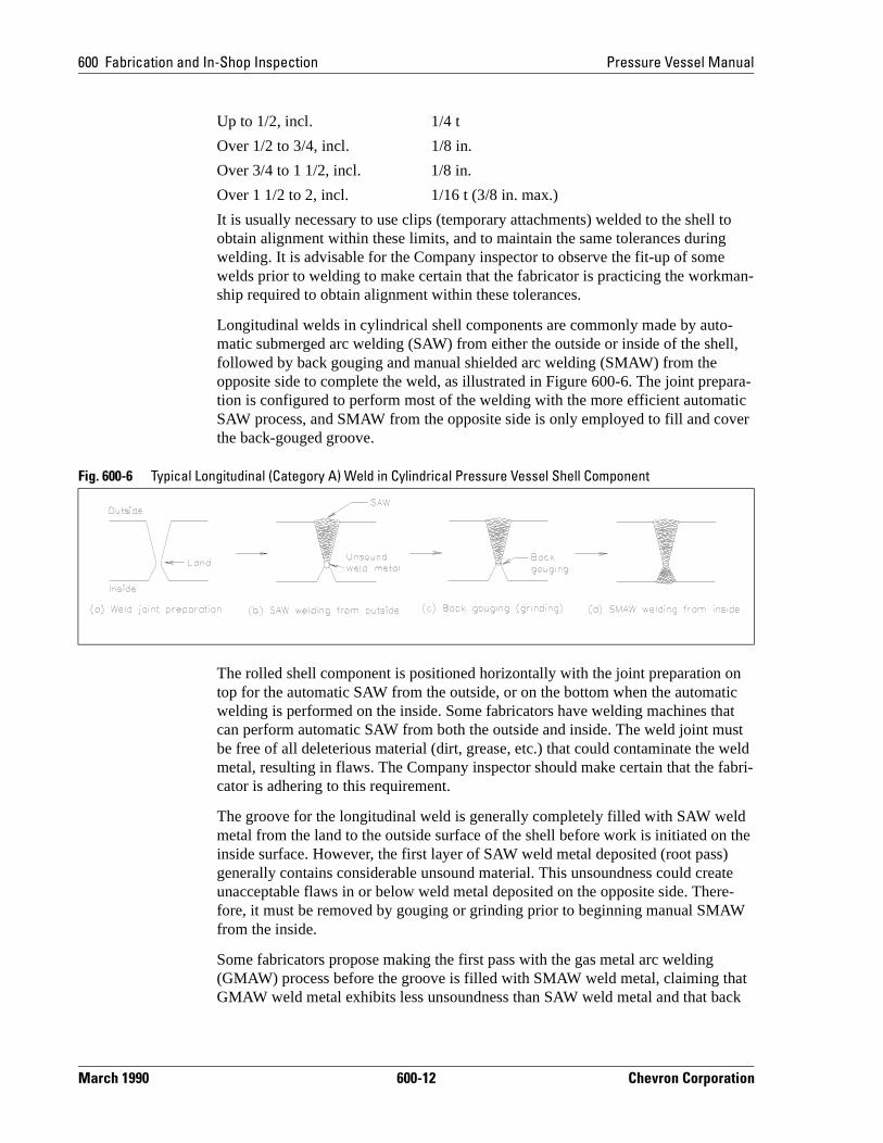
Longitudinal welds in cylindrical shell components are commonly made by auto-matic submerged arc welding (SAW) from either the outside or inside of the shell, followed by back gouging and manual shielded arc welding (SMAW) from the opposite side to complete the weld, as illustrated in Figure 600-6. The joint prepara-tion is configured to perform most of the welding with the more efficient automatic SAW process, and SMAW from the opposite side is only employed to fill and cover the back-gouged groove.
The rolled shell component is positioned horizontally with the joint preparation on top for the automatic SAW from the outside, or on the bottom when the automatic welding is performed on the inside. Some fabricators have welding machines that can perform automatic SAW from both the outside and inside. The weld joint must be free of all deleterious material (dirt, grease, etc.) that could contaminate the weld metal, resulting in flaws. The Company inspector should make certain that the fabri-cator is adhering to this requirement.
The groove for the longitudinal weld is generally completely filled with SAW weld metal from the land to the outside surface of the shell before work is initiated on the inside surface. However, the first layer of SAW weld metal deposited (root pass) generally contains considerable unsound material. This unsoundness could create unacceptable flaws in or below weld metal deposited on the opposite side. There-fore, it must be removed by gouging or grinding prior to beginning manual SMAW from the inside.
Some fabricators propose making the first pass with the gas metal arc welding (GMAW) process before the groove is filled with SMAW weld metal, claiming that GMAW weld metal exhibits less unsoundness than SAW weld metal and that back
Up to 1/2, incl. 1/4 t
Over 1/2 to 3/4, incl. 1/8 in.
Over 3/4 to 1 1/2, incl. 1/8 in.
Over 1 1/2 to 2, incl. 1/16 t (3/8 in. max.)
Fig. 600-6 Typical Longitudinal (Category A) Weld in Cylindrical Pressure Vessel Shell Component
March 1990 600-12 Chevron Corporation

Pressure Vessel Manual 600 Fabrication and In-Shop Inspection
, er
s els
pot es sed of or
nd
e.
raphs all
gouging will not be necessary. However, substituting GMAW for backgouging or grinding can lead to a high incidence of rejectable welds, and is not acceptable.
When it is not possible to weld from the inside, such as with rolled and welded nozzle barrels, it is acceptable to employ a single-V weld preparation with gas Tungsten arc welding (GTAW) of the first layer of weld metal (root pass), followed by filling the remainder of the groove with SAW or SMAW weld metal. Careful GTAW is capable of producing a root bead contour on the inside surface that is equivalent to a Type 1 double-welded joint. The company inspector should visually examine the inside surface of the GTAW root beads to make certain that the fabri-cator is obtaining good contours.
It is essential that all of the welding procedures used by the fabricator are properly qualified according to ASME Code, Section IX, and that these procedures are strictly adhered to during production welding. The Company inspector should assure that the fabricator is adhering to the qualified welding procedures, including preheat wherever required, by surveillance on the shop floor during fabrication.
Some distortion (or “Peaking”) can occur during welding of the longitudinal jointand, consequently, the cylindrical shell components may have to be rerolled aftwelding to be within the ASME Code tolerances for out-of-roundness. Alterna-tively, some fabricators control distortion by joint configuration and weld bead sequence, balancing welding from the outside and inside. ASME Code, SectionVIII, Divisions 1 and 2, prohibits out-of-roundness from exceeding 1% of the nominal diameter for which the component is designed (Paragraphs UG-80 andAF-130). The tolerances for alignment of girth welds must also be obtained.
NDEASME Code, Section VIII, Division 1 (Paragraphs UW-11 and UCS-57), requireRT examination of longitudinal welds for shell components of carbon steel vessexceeding 1¼-inches thick, for low-alloy 1¼ Cr—1 Mo vessels exceeding 5/8 inches, and for all low-alloy 2¼ Cr—1 Mo vessels regardless of thickness. SRT or VT (i.e., no RT) is permitted for components of vessels having thicknessthat are thinner than these limits, providing reduced weld joint efficiencies are ufor the design (Paragraph UW-12). However, the pressure vessel specificationsrecommend spot RT as a minimum, and allow the option of full RT examinationvessels when not required by the Code. Full RT examination is recommended fthe following conditions:
1. For service at low temperatures where undetected flaws could cause brittlefracture.
2. For service where cyclic pressures and/or temperatures are encountered, aundetected flaws could initiate fatigue cracks.
See the comments in PVM-MS-4750, Inspection Section, for additional guidanc
ASME Code, Section VIII, Division 2, requires full RT of all longitudinal welds regardless of thickness. The authorized inspector is obligated to review all radiogthat are required by the ASME Code, but the Company inspector will also review radiographs, especially those that are specified exceeding Code requirements.
Chevron Corporation 600-13 March 1990
600 Fabrication and In-Shop Inspection Pressure Vessel Manual
The pressure vessel specification PVM-MS-4749 recommends UT examination of all longitudinal welds in shell components 3-inches thick or greater, or when GMAW is employed, regardless of thickness, in addition to the RT examination required by the Code and/or the specification. The Company inspector should witness the UT examination performed by the fabricator to verify that the examina-tions are being performed properly, and that the results are being accurately recorded.
652 Nozzle WeldsNozzle welds (Category D welds) can be the most difficult welds to make. More flaws are encountered in these welds than in longitudinal welds (Category A welds) and girth welds (Category B welds). Furthermore, nozzle welds are subjected to relatively high and complex stresses, especially if piping connections apply external loads and moments. The pressure vessel specifications PVM-MS-4749 and PVM-MS-4750 recommend NDE of these welds, exceeding ASME Code requirements for vessels that will be 100% radiographed, in order to assure that they will provide adequate integrity and reliability for severe service conditions.
WeldingDrop-outs (i.e., holes) are cut into the shell or head components of a vessel, usually using oxyfuel gas cutting, and the weld bevels (joint preparations) are also oxyfuel gas cut or machined. The nozzle barrel is then inserted into the opening, and the proper fit-up for welding is maintained by the use of clips (temporary attachments) welded to the shell component and nozzle. It is advisable for the company inspector to observe the fit-up of some nozzles prior to welding to assure that the fabricator is exercising good workmanship practices, that full penetration is being achieved, and that the specified tolerances for orientation and elevation will be achieved.
Nozzles can be welded into shell and head components either before or after the various components are joined together depending on the fabricator’s shop facilities and the most efficient plan for final assembly. Welding the nozzles into the shell or head component is generally accomplished by manual SMAW. Automatic SAW is sometimes used for large diameter nozzles in relatively thick shells. Some fabrica-tors like to use semiautomatic FCAW, which can be more efficient than manual welding due to the continuous wire feed. However, a high incidence of underbead cracking can occur with FCAW unless low-hydrogen electrodes are used. This concern is addressed in the Company specifications. Also see Section 660 for more details.
It is essential that the fabricator use only welding procedures that have been prop-erly qualified according to ASME Code, Section IX. The Company inspector should maintain adequate surveillance on the shop floor to assure that the fabricator is strictly adhering to the qualified procedures, including preheat.
When integrally reinforced nozzle forgings are used (see Figure 600-4), double-V joint preparations are generally employed to permit welding from both the inside and outside surfaces, similar to that described for the welding of longitudinal joints (see Section 651). However, when “built-up” nozzles with a reinforcing pad are
March 1990 600-14 Chevron Corporation
Pressure Vessel Manual 600 Fabrication and In-Shop Inspection
used (see Figure 600-5), a single-V joint preparation is more commonly used for installation of the nozzle barrel, with all of the welding performed from the inside. The outside surface of the weld is subsequently gouged or ground to remove unsound weld metal, and the reinforcing pad is then welded to the nozzle barrel and shell component from the outside.
The company inspector should determine that all of the specified tolerances for orientation and elevation have been obtained after the welding is completed, because some distortion can occur during welding. Refer to Standard Drawings GA-C1266 (horizontal vessels) or GA-C1267 (vertical vessels) for recommended tolerances.
Also refer to Section 660 for more specific information on welding pressure vessels, and to the Welding Manual for welding in general.
NDEASME Code, Section VIII, Division 1, does not require any NDE of nozzle welds (Category D welds), regardless of the extent of RT and the joint efficiency used for design of the vessel. The configuration of most nozzle welds (see Figure 600-5) usually does not permit satisfactory RT. However, ASME Code, Section VIII, Divi-sion 2 (Paragraph AF-240), requires UT examination of these welds if RT cannot be satisfactorily performed.
653 Girth WeldsThe cylindrical shell and head components are joined together with girth welds (Category B welds). These welds are usually made using a welding procedure employing a combination of automatic SAW and manual SMAW that is very similar to those described for longitudinal welds.
WeldingThe cylindrical shell (or head) components to be joined together are positioned hori-zontally on rolls that can revolve the mating components in unison for girth welding. ASME Code, Section VIII, Divisions 1 and 2, requires obtaining the following tolerances for misalignment of the girth welds (Paragraphs UG-80 and AF-142):
These tolerances are somewhat larger than required for longitudinal welds (see Section 651). Nevertheless, it is almost always necessary to use clips or strong
Section Thickness (t), in. Misalignment Tolerances
Up to 1/2, incl. 1/4 t
Over 1/2 to 3/4, incl. 1/4 t
Over 3/4 to 1 1/2, incl. 3/16 in.
Over 1 1/2 to 2, incl. 1/8 t
Over 2 1/8 t (3/4 in. max.)
Chevron Corporation 600-15 March 1990
600 Fabrication and In-Shop Inspection Pressure Vessel Manual
backs (temporary attachments) welded to the mating components to obtain fit-up within these limits, and to assure that they are maintained during welding. The company inspector should observe the fit-up of several of these welds to make certain that the fabricator is exercising the good workmanship practices necessary to achieve fit-up within the required limits.
As for longitudinal welds, most of the welding is performed by SAW from the outside or inside of the shell. The mating shell (or head) components being welded are tacked together, and are then revolved in unison under the welding head, so the weld metal is deposited in the groove between the two components. Subsequently, the unsound SAW weld metal in the root pass is removed by back gouging or grinding, and the weld is completed by manual SMAW from the opposite side of the shell. The discussion for welding of longitudinal joints (see Section 651) also applies to girth welding.
NDEASME Code, Section VIII, Division 1, has recently changed the requirements for NDE to permit spot RT of girth welds (Category B welds) when full RT is required for longitudinal welds (Category A welds) for design with a joint efficiency of 1.0. The justification is that the maximum stress transverse to a girth weld is nominally one-half that in a longitudinal weld. ASME Code, Section VIII, Division 2, does not allow relaxation of the RT coverage of girth welds. The Company inspector should verify that the fabricator is conforming to the requirement in the specifications for full coverage RT.
All other NDE requirements for girth welds are the same as those discussed for longitudinal welds (see Section 652).
654 Skirt Attachment WeldAttaching a support skirt to a pressure vessel does not involve a pressure containing weld. Nevertheless, the skirt attachment weld must be made properly to provide the integrity required to reliably support the vessel, including the maximum wind and earthquake loads that might occur, and in a manner that does not jeopardize the pressure containing integrity of the vessel. The skirt is usually fabricated by rolling and welding, similar to the formation of the cylindrical shell components of the vessel (see Section 630).
WeldingASME Code, Section VIII, Divisions 1 and 2 (Paragraphs UW-28c and AF-210.4), requires that the welding procedure used for the attachment of a support skirt to a pressure vessel be qualified according to ASME Code, Section IX. The welding procedure should be very similar to those used for pressure- containing welds in the vessel, including requirements for preheat and postweld heat treatment.
A support skirt can be directly welded to the bottom head of a pressure vessel, as shown in Figure 600-7a. Automatic SAW or manual SMAW is normally used to make this type of skirt attachment weld. This type of skirt attachment cannot be
March 1990 600-16 Chevron Corporation

Pressure Vessel Manual 600 Fabrication and In-Shop Inspection
.”
own vy uld nual kirt.
HT).
readily nondestructively examined, and flaws almost always exist in the “crotchThese flaws could propagate by fatigue if they are subjected to thermal cycling.
Attachment of the support skirt to the bottom head employing a weld pad as shin Figure 600-7b provides a higher integrity attachment that is preferred for heaand thick wall vessels, or those that will be subjected to thermal cycling that coinitiate fatigue cracks. The weld pad can be deposited on the head by either maSMAW or automatic SAW. The weld pad is subsequently machined to a smoothcontour that incorporates a weld bevel (joint preparation) for attachment of the sThe skirt is then welded to the machined weld pad, and this joint preparation permits either RT or UT examination.
655 Postweld Heat TreatmentSee Section 660 for guidance on when to perform postweld heat treatment (PW
Note PWHT is a very important factor that can have a significant effect on the integrity and reliability of the vessel. Omitted or improperly performed postweld heat treatments can lead to failure of the vessel.
Fig. 600-7 Support Skirt Attachment to a Pressure Vessel
Chevron Corporation 600-17 March 1990
600 Fabrication and In-Shop Inspection Pressure Vessel Manual
ntire e ermal
it is pres-t-
the
e ode o
A -
ay be
o
ssel it is e d
The pressure vessel specifications recommend attaching sufficient thermocouples to the vessel during postweld heat treatment to assure that the minimum temperature for postweld heat treatment required by the ASME Code or the specifications has been obtained, and the temperature should not vary more than 50°F over the evessel. Temperature variations during heating and cooling should not vary morthan 150°F over the entire vessel, to prevent damage by the development of thstresses.
Postweld heat treatment can be performed locally for individual welds, when a completed vessel is too large to fit inside of the heat treating furnace. However,very important to make certain that the temperature gradients resulting from thelocal heat treatment do not develop thermal stresses that damage the vessel. Asure vessel engineer should review the fabricator's procedure for local heat treament of the vessel.
It is important that no welding is performed on pressure containing compo-nents of a vessel after it is postweld heat treated. Occasionally, by oversight, some external attachments to the vessel shell must be welded to the shell afterpostweld heat treatment has been performed. If this occurs, a second PWHT isrequired.
The Company inspector should maintain sufficient surveillance to assure that thpostweld heat treatment is properly performed in accordance with the ASME Cand any additional requirements in the pressure vessel specification, and that nwelding is performed after the vessel is heat treated.
660 Welding Processes and Procedures
661 Welding ProcessesNumerous welding processes are available for fabrication of pressure vessels. brief description of commonly used welding processes, with their typical applications and limitations, are presented below. More detailed information on these common welding processes and information on some uncommon processes mfound in Section 100 of the Welding Manual.
SMAWSMAW (shielded metal arc welding), commonly referred to as “stick” welding, isstrictly a manual process that uses a consumable flux-coated metal electrode tprovide filler metal, flux, and slag. (See Figures 600-8 and 600-9.)
The SMAW process is the most versatile welding process used for pressure vefabrication. It can be used for all positions, thicknesses, and joint designs; and equally suited for shop or field fabrication. This process is preferred for pressurvessel nozzle and attachment welds. It is also acceptable for circumferential anlongitudinal welds in lieu of the typically used SAW process (discussed below).
March 1990 600-18 Chevron Corporation
Pressure Vessel Manual 600 Fabrication and In-Shop Inspection
es e as is s is t )
gh
not ons. It er-y not
GTAWGTAW (gas tungsten arc welding), commonly referred to as “TIG” welding, utiliza nonconsumable tungsten electrode and separate filler metal in the form of wir(separate filler metal is not always used for very thin sections). Inert shielding gsupplied through an annular nozzle around the tungsten electrode. The procesmuch better suited for shop fabrication than field fabrication since air movemenmust be less than 5 mph to maintain the inert gas blanket. (See Figure 600-10.
GTAW is predominantly a manual process, but automatic processes have beendeveloped. The automatic GTAW processes, however, are used primarily for hiquality pipe and tube welding.
The manual GTAW process has specific, but limited, applications for pressure vessel fabrication. This process is preferred for root passes of welds which canbe backwelded, such as vessel-closure welds or welds on small diameter sectiis also sometimes used for welding very thin stainless steel parts like vessel intnals. This process can be used for all positions, but welding confined joints ma
Fig. 600-8 Typical Welding Circuit for Shielded Metal Arc Welding (SMAW)
Fig. 600-9 Shielded Metal Arc Welding (SMAW) From AWS Welding Handbook, Vol 2, 8th ed., ed. by O’Brien. Used with permission.
Chevron Corporation 600-19 March 1990

600 Fabrication and In-Shop Inspection Pressure Vessel Manual
s the tact
s to-
three
ee
fabri-
be feasible because GTAW requires both of the welder’s hands. The manual GTAW process is also slow, and typically not economically attractive for thick welds or filler passes due to low deposition rates.
GMAWGMAW (gas metal arc welding), commonly referred to as “MIG” welding, utilizean automatically fed consumable electrode in the form of wire from a spool for filler metal. Inert shielding gas is supplied through an annular nozzle at the contip of the gun. The process is much better suited for shop fabrication than field fabrication since air movement must be less than 5 mph to maintain the inert gablanket. (See Figures 600-11 and 600-12.) GMAW is a predominantly a semiaumatic process, but automatic processes are sometimes used for weld overlays.
Depending on the current, voltage (arc length), and shielding gas composition, modes of metal transfer are commonly used for GMAW:
• Short circuiting transfer (also called short-arc or interrupted-arc transfer). (SFigure 600-13.)
• Globular transfer. (See Figure 600-14.)
• Spray transfer. (Pulsed-current is a variation of spray transfer.) (See Figure600-15.)
Short circuiting transfer GMAW is a low heat input form of welding which can beused for all positions. However, the process is notorious for producing lack-of-fusion defects. Therefore this process is not recommended for pressure vesselcation, except for the following applications:
• Root passes on circumferential, longitudinal, or nozzle-to-shell weld only if backgouged and backwelded
Fig. 600-10 Equipment for Gas Tungsten Arc Welding (GTAW) From AWS Welding Hand-book, Vol 2, 8th ed., ed. by O’Brien. Used with permission.
March 1990 600-20 Chevron Corporation

Pressure Vessel Manual 600 Fabrication and In-Shop Inspection
al
• Root passes on circumferential piping welds for fabricated nozzles or internpiping• Root passes on nonpressure containing vessel internals.
Fig. 600-11 Equipment for Gas Metal Arc Welding (GMAW) From AWS Welding Handbook, Vol 2, 8th ed., ed. by O’Brien. Used with permission.
Fig. 600-12 Gas Metal Arc Welding Process (GMAW) From AWS Welding Handbook, Vol 2, 8th ed., ed. by O’Brien. Used with permission.
Fig. 600-13 GMAW—Short Circuiting Transfer From AWS Welding Handbook, Vol 2, 8th ed., ed. by O’Brien. Used with permission.
Chevron Corporation 600-21 March 1990
600 Fabrication and In-Shop Inspection Pressure Vessel Manual
Globular and spray transfer GMAW processes are high heat input processes which are acceptable for pressure vessel fabrication. The major drawback of these processes for vessel fabrication is that they are generally limited to the flat position. Therefore, they are typically used only for circumferential and longitudinal welds, rather than for nozzle and attachment welds. They must compete with the faster SAW process (discussed below) for welding applications and are hence not common for pressure vessel fabrication.
A modification of the spray transfer GMAW process, pulsed-current GMAW, utilizes a pulsed current and smaller diameter wire to achieve all-position capabili-ties. Typical applications are for corrosion-resistant overlays and nozzle welds.
FCAWFCAW (flux cored arc welding) is a variation of the GMAW process which uses flux-cored wire instead of solid bare wire. Among other things, the flux forms a slag which helps hold the molten metal in place so the process can be used for all posi-tions.
FCAW processes are used primarily in the spray transfer mode, but globular transfer is not uncommon. The processes are noted for high deposition rates. Applications include nozzle welds and welds to vessel attachments such as stiffening rings, insu-lation support rings, internals, and supports.
FCAW processes can be either gas-shielded or self-shielded (with or without inert shielding gas). (See Figures 600-16 and 600-17.) The gas-shielded FCAW process (FCAW-G), like the GMAW process, is much better suited for shop fabrication than field fabrication since air movement must be less than 5 mph to maintain the inert
Fig. 600-14 GMAW—Globular Transfer From AWS Welding Handbook, Vol 2, 8th ed., ed. by O’Brien. Used with permission.
Fig. 600-15 GMAW—Spray Transfer From AWS Welding Handbook, Vol 2, 8th ed., ed. by O’Brien. Used with permission.
March 1990 600-22 Chevron Corporation
Pressure Vessel Manual 600 Fabrication and In-Shop Inspection
gas blanket. The self-shielded FCAW process (FCAW-SS) is equally suited for either shop or field fabrication.
The FCAW-SS process should not be accepted for pressure vessel fabrication without special review by a materials or welding specialist, on a case-by-case basis. This precaution should be taken because of the need for careful consumable selec-tion and the significant training and supervision required to obtain reliable welds with this process. Furthermore, the FCAW-G process is acceptable for pressure
Fig. 600-16 Gas Shielded Flux Cored Arc Welding (FCAW-G) From AWS Welding Handbook, Vol 2, 8th ed., ed. by O’Brien. Used with permission.
Fig. 600-17 Self-Shielded Flux Cored Welding (FCAW-SS) From AWS Welding Handbook, Vol 2, 8th ed., ed. by O’Brien. Used with permission.
Chevron Corporation 600-23 March 1990
600 Fabrication and In-Shop Inspection Pressure Vessel Manual
les
vessel fabrication only if special low-hydrogen flux-cored wire is used (See Section 662 below).
SAWThe SAW (submerged arc welding) process uses a continuously fed consumable electrode (or electrodes) in the form of a wire or strip (for weld overlays) from a coil and a granular flux. The process is similar to GMAW except that the arc is submerged in a granular flux which melts and provides shielding from the atmo-sphere. Because of the need to hold the flux in place until the molten metal cools, the process is almost always used in the flat position (See Figure 600-18). However, some specialized equipment has been developed for supporting the flux in the hori-zontal position to make girth seams on large field-erected storage tanks.
SAW is predominantly an automatic welding process with mechanized equipment which controls travel speed. Because SAW is used primarily for welding vessel seams in the flat position, positioning of seams to accommodate welding is required. This requires turning rolls for welding longitudinal and circumferential shell seams and positioners for welding head seams. A wide range of deposition rates can be obtained with the process and even higher productivity can be obtained when more than one electrode is used (e.g., tandem electrodes). Welds are generally of high quality and have good mechanical properties when the proper welding consumables (wire/flux combination) are selected.
662 ConsumablesFiller metal, flux, shielding gas, and backing gas are included in the category of “consumables.” This section is intended only as a brief discussion of consumab
Fig. 600-18 Submerged Arc Welding (SAW) From AWS Welding Handbook, Vol 2, 8th ed., ed. by O’Brien. Used with permission.
March 1990 600-24 Chevron Corporation
Pressure Vessel Manual 600 Fabrication and In-Shop Inspection
eer.
for commonly used welding processes. See Sections 100, 300, and Appendix A of the Welding Manual for more detailed information on consumables and welding processes discussed below, or for information on uncommon consumables and welding processes not included here.
Filler MetalsIn general, the main requirements for a filler metal are:
• Compatibility with the base material
• Mechanical properties that meet or exceed the mechanical properties of thebase metal after welding (and when required, after heat treatment)
• Satisfactory corrosion resistance for the process environment
• Produces a sound weld when properly applied
Recommended filler metals for commonly used pressure vessel materials and welding processes are summarized in Figure 600-19. Other filler metals may beacceptable if reviewed on a case-by-case basis by a welding or materials engin
Fig. 600-19 Filler Metal Selection Summary for Common Pressure Vessel Applications
SMAW GTAW GMAW FCAW-G(1) SAW
CS Vessels E7018 per AWS A5.1(2)
ER70S-2/3/6 per AWS A5.18
ER70S-2/3/6 per AWS A5.18
E7XT-1/5 per AWS A5.20(3)
F7P2-EA1/EA2 (PWHT’d) or F7A2-EM12K (as welded) per AWS A5.17(4)
C-1/2Mo Vessels
E7018-A1 per AWS A5.5 (2)
ER80S-D2 per AWS A5.28(5)
ER80S-D2 per AWS A5.28(5)
E70T5-A1 or E8XT-A1 per AWS A5.29(3), (6)
F7X2-EA1/EA2 per AWS A5.23(4)
1 1/4Cr-1/2Mo Vessels
E8018-B2 per AWS A5.5
ER80S-B2 per AWS A5.28
ER80S-B2 per AWS A5.28
E8XT1-B2 or E8XT5-B2 per AWS A5.29(3), (6)
FXXX-EB2 per AWS A5.23(4)
2 1/4Cr-1Mo Vessels
E9018-B3 per AWS A5.5
ER90S-B3 per AWS A5.28
ER90S-B3 per AWS A5.28(5)
E9XT1-B3 or E9XT5-B3 per AWS A5.29(3), (6)
FXXX-EB3 per AWS A5.23(4)
5Cr-1/2Mo Vessels
E502 per AWS A5.4
ER502 per AWS A5.9
ER502 per AWS A5.9
E502T-1 per AWS A5.22(3), (6)
F7X2-EB6 per AWS A5.23(4)
Type 304L SS Vessels
E308L per AWS A5.4
ER308L per AWS A5.9
ER308L per AWS A5.9
E308LT-1 per AWS A5.22(6)
ER308L(7)
Type 316L SS Vessels
E316L per AWS A5.4
ER316L per AWS A5.9
ER316L per AWS A5.9
E316LT-1 per AWS A5.22(6)
ER316L(7)
Type 347/321 SS Vessels
E347 per AWS A5.4
ER347 per AWS A5.9
ER347 per AWS A5.9
E347T-1 per AWS A5.22(6)
ER347(7)
(1) Filler metals shown are for the FCAW-G process only. Do not use the FCAW-SS process for pressure vessel fabrication unless reviewed on a case-by-case basis by a welding or materials engineer.
Chevron Corporation 600-25 March 1990
600 Fabrication and In-Shop Inspection Pressure Vessel Manual
(2) Only low hydrogen electrodes (E7018, etc.) are acceptable for CS and alloy steel welds. Cellulosic flux electrodes (E6010, etc.) and other non-low hydrogen electrodes are not acceptable. Cellulosic flux electrodes may, on rare occasions, be used for root passes of one-sided welds if carefully reviewed by a welding or materials engineer.
(3) Only low hydrogen FCAW electrodes are acceptable for CS and alloy steel welds. “Low hydrogen” is defined as, “less than 10 ml/100 gm of diffusible hydrogen in typical as-deposited weld metal, measured by the mercury displacement or gas chromatograph methods per AWS A4.3.” Note that this requirement is supplementary to (and not covered by) applicable AWS specifications.
(4) Wire and flux combinations for SAW processes should be selected for appropriate strength level and composition, since SAW flux can add significant alloy content to weld metal.
(5) C-1/2Mo welds with 80 ksi filler metals must be stress relieved for wet H2S services to prevent sulfide stress cracking.(6) Use of FCAW-G processes for alloy and stainless steel welds should only be accepted after careful review by a welding or materials
engineer.(7) There is no AWS specification for SAW filler metals for austenitic stainless steels. Use Lincoln ST-100 or Linde 80 flux. Other fluxes
should be approved by a welding or materials engineer.
March 1990 600-26 Chevron Corporation
Pressure Vessel Manual 600 Fabrication and In-Shop Inspection
nd
-8 the
ld s-ury at the
he e.
es
ape
e
on igh of i-es-
FluxFlux is used in several different forms depending upon the welding process. For the SMAW process, it is extruded as a coating on the electrodes. For the FCAW process, it is added as a powder inside the cored electrode. For the SAW process, it is deposited on the work ahead of the welding arc as a loose granular material. No flux is used for the GTAW and GMAW processes. Flux serves some or all of the following functions:
• Stabilizes the welding arc
• Shields the arc and molten metal from atmospheric oxygen and nitrogen contamination
• Forms a slag blanket over the molten weld metal to help hold it in position aprovide further shielding from contamination during cooling
• Provides deoxidizers (Mn and Si) to improve weld metal soundness and alloying elements (e.g., Cr, Mo, or Ni) for low alloy welds
To avoid underbead cracking in pressure vessel steels, SMAW and FCAW electrodes and SAW fluxes should be specified as a low hydrogen type (e.g., EXX1electrodes) and must be kept clean and dry to prevent hydrogen absorption intoweld metal and heat affected zones. Low hydrogen electrodes and fluxes shouimpart no more than 10 ml of diffusible hydrogen per 100 gm of typical as-depoited weld metal per the manufacturer's specifications, as measured by the mercdisplacement or gas chromatograph methods per AWS A4.3. Note, however, thASME Code does not require the use of low hydrogen electrodes and fluxes.
Shielding GasShielding gases for GTAW, GMAW and FCAW-G processes are used to shield twelding arc and molten weld metal from nitrogen and oxygen in the atmospherInert shielding gases (argon and helium) are required for the GTAW process to avoid contamination of the tungsten electrode. The most common shielding gasfor the GMAW and FCAW-G processes are Ar, CO2, and combinations of the two. The exact shielding gas composition is selected to provide the desired bead shand to minimize spatter. (100% CO2 shielding is cheaper but produces greater amounts of spatter.) Other less common shielding gases are also acceptable. Ar-O2 mixtures are sometimes used for low alloy steels (e.g., 2¼ CR-1Mo) andHe-Ar-CO2 mixtures are sometimes used for austenitic stainless steels (i.e., Typ304L). Refer to Appendix A of the Welding Manual for various alloys and welding processes.
Backing GasInert backing gas (such as Ar, CO2, or possibly N2 for stainless steel vessels) is required with GMAW and GTAW processes for root passes of one-sided welds alloys with more than 3% Cr content. Inert backing gas is required to prevent htemperature oxidation of Cr (sometimes called “sugaring”) on the inner surfacethe weld. To use inert backing gas for pressure vessel fabrication is usually diffcult, and can entail purging large volumes. Special precautions are usually nec
Chevron Corporation 600-27 March 1990
600 Fabrication and In-Shop Inspection Pressure Vessel Manual
tial lly
wn l, is
king
d by:
the
sary to localize the purging area, and one-sided welds should only be used where absolutely necessary.
663 Preheat and Interpass Temperature Control
PreheatingPreheating is the process of raising the temperature of the base metal above ambient temperature immediately before welding and holding it during welding. Preheating is not recommended for austenitic stainless steels. However, for carbon and alloy steels it is extremely important. Preheating carbon and alloy steels accomplishes the following functions:
• Reduces residual stresses, shrinkage, and distortion by minimizing differenthermal expansion between the weld metal and base metal. This is especiaimportant for welds on thick sections or welds with high restraint.
• Reduces weld metal and heat affected zone (HAZ) hardness by slowing dothe cooling rate. The driving temperature gradient between the molten weldmetal and base metal, as well as the thermal conductivity of the base metareduced by preheat. See Figure 600-20.
• Increases the diffusion rate of hydrogen from the weld metal and HAZ. Thishelps prevent hydrogen embrittlement cracking (also called underbead cracor delayed hydrogen cracking) of the weldment when it cools to ambient temperature.
Minimum preheat temperatures for carbon and alloy steels are primarily determine
The hardenability of the weld metal and HAZ. This is determined by a calcu-lated “carbon equivalent (CE)” factor. Basically, the greater the CE, the greater required preheat. See Section 140 of the Welding Manual for more information on
Fig. 600-20 Effects of Preheating. From The Procedure Handbook of Arc Welding. Courtesy of the Lincoln Electric Co.
March 1990 600-28 Chevron Corporation
Pressure Vessel Manual 600 Fabrication and In-Shop Inspection
CE and how it affects preheat. See Figure 600-21 for the effect of hardenability (or CE) and preheat on underbead cracking susceptibility.
The amount of restraint in the weldment. For pressure vessels, this is primarily dependent on metal thickness.
The hydrogen charging characteristics of the fluxes or electrodes. This is not usually a consideration if low hydrogen electrodes or fluxes are used. If non-low hydrogen fluxes or electrodes are required for some reason, then the minimum required preheat should be increased appropriately. Consult a welding or materials engineer.
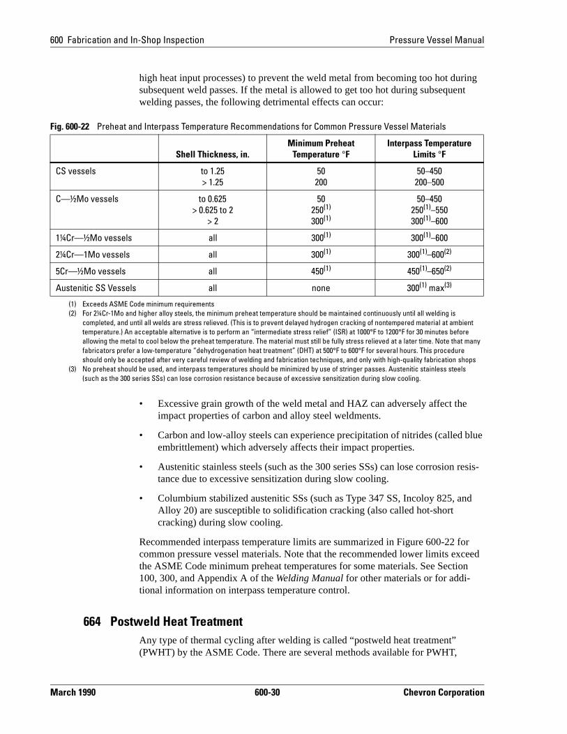
Minimum recommended preheat temperatures are summarized in Figure 600-22 for common pressure vessel materials. Note that these recommendations exceed the ASME Code minimum values for some materials. See Sections 100, 300, and Appendix A of the Welding Manual for other materials or for additional informa-tion on preheating.
Interpass Temperature ControlInterpass temperature control is a process of controlling the temperature of the deposited weld metal between specified limits during multipass welds. The lower limit is usually the same as the minimum preheat temperature, and accomplishes the same functions. However, an upper limit is also relevant (especially when utilizing
Fig. 600-21 Effect of Preheat and Carbon Equivalent on Underbead Cracking Susceptibility
Note:This figure is an example of the effect of preheating on underbead cracking susceptibility for a weld bead deposited on a test plate. This figure should not be used for selecting preheat temperatures for pressure vessel welds. Figure 600-22 should be used instead.
Chevron Corporation 600-29 March 1990
600 Fabrication and In-Shop Inspection Pressure Vessel Manual
blue
resis-
nd
or ceed
on
high heat input processes) to prevent the weld metal from becoming too hot during subsequent weld passes. If the metal is allowed to get too hot during subsequent welding passes, the following detrimental effects can occur:
• Excessive grain growth of the weld metal and HAZ can adversely affect theimpact properties of carbon and alloy steel weldments.
• Carbon and low-alloy steels can experience precipitation of nitrides (called embrittlement) which adversely affects their impact properties.
• Austenitic stainless steels (such as the 300 series SSs) can lose corrosion tance due to excessive sensitization during slow cooling.
• Columbium stabilized austenitic SSs (such as Type 347 SS, Incoloy 825, aAlloy 20) are susceptible to solidification cracking (also called hot-short cracking) during slow cooling.
Recommended interpass temperature limits are summarized in Figure 600-22 fcommon pressure vessel materials. Note that the recommended lower limits exthe ASME Code minimum preheat temperatures for some materials. See Secti100, 300, and Appendix A of the Welding Manual for other materials or for addi-tional information on interpass temperature control.
664 Postweld Heat TreatmentAny type of thermal cycling after welding is called “postweld heat treatment” (PWHT) by the ASME Code. There are several methods available for PWHT,
Fig. 600-22 Preheat and Interpass Temperature Recommendations for Common Pressure Vessel Materials
Shell Thickness, in.Minimum Preheat
Temperature °FInterpass Temperature
Limits °F
CS vessels to 1.25> 1.25
50200
50–450200–500
C—½Mo vessels to 0.625> 0.625 to 2
> 2
50250(1)
300(1)
50–450250(1)–550300(1)–600
1¼Cr—½Mo vessels all 300(1) 300(1)–600
2¼Cr—1Mo vessels all 300(1) 300(1)–600(2)
5Cr—½Mo vessels all 450(1) 450(1)–650(2)
Austenitic SS Vessels all none 300(1) max(3)
(1) Exceeds ASME Code minimum requirements(2) For 2¼Cr-1Mo and higher alloy steels, the minimum preheat temperature should be maintained continuously until all welding is
completed, and until all welds are stress relieved. (This is to prevent delayed hydrogen cracking of nontempered material at ambient temperature.) An acceptable alternative is to perform an “intermediate stress relief” (ISR) at 1000°F to 1200°F for 30 minutes before allowing the metal to cool below the preheat temperature. The material must still be fully stress relieved at a later time. Note that many fabricators prefer a low-temperature “dehydrogenation heat treatment” (DHT) at 500°F to 600°F for several hours. This procedure should only be accepted after very careful review of welding and fabrication techniques, and only with high-quality fabrication shops
(3) No preheat should be used, and interpass temperatures should be minimized by use of stringer passes. Austenitic stainless steels (such as the 300 series SSs) can lose corrosion resistance because of excessive sensitization during slow cooling.
March 1990 600-30 Chevron Corporation
Pressure Vessel Manual 600 Fabrication and In-Shop Inspection
com-
d all -t
which vary in temperature and cooling rate, as well as resulting material properties. PWHT processes, various methods of heating, and heating and cooling rate limita-tions are discussed in detail in Section 100 of the Welding Manual. The most common PWHT processes are briefly discussed below.
Stress Relief Heat TreatmentThe most common form of PWHT is a “stress relief” or “tempering” heat treat-ment. This heat treatment involves heating the material to a temperature high enough to significantly relax residual stresses from welding, but low enough to avoid metallurgical phase transformation. Heat treatment at this temperature acplishes the following functions:
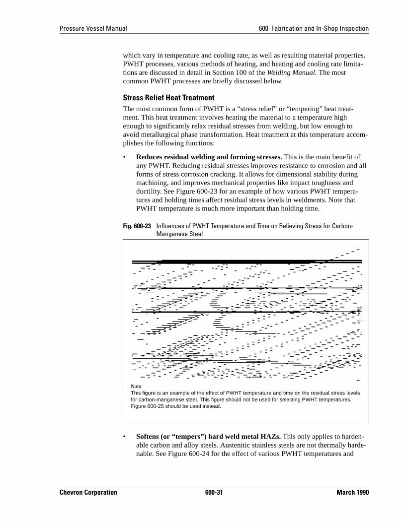
• Reduces residual welding and forming stresses. This is the main benefit of any PWHT. Reducing residual stresses improves resistance to corrosion anforms of stress corrosion cracking. It allows for dimensional stability duringmachining, and improves mechanical properties like impact toughness andductility. See Figure 600-23 for an example of how various PWHT temperatures and holding times affect residual stress levels in weldments. Note thaPWHT temperature is much more important than holding time.
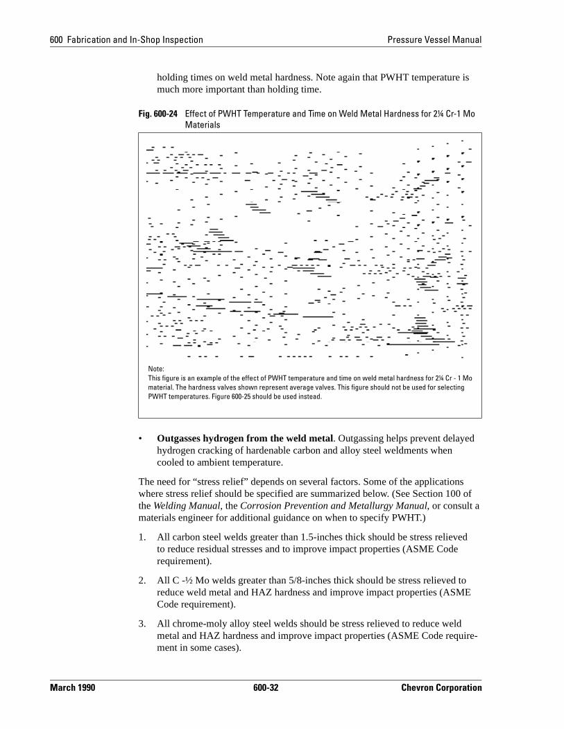
• Softens (or “tempers”) hard weld metal HAZs. This only applies to harden-able carbon and alloy steels. Austenitic stainless steels are not thermally harde-nable. See Figure 600-24 for the effect of various PWHT temperatures and
Fig. 600-23 Influences of PWHT Temperature and Time on Relieving Stress for Carbon-Manganese Steel
Note:This figure is an example of the effect of PWHT temperature and time on the residual stress levels for carbon-manganese steel. This figure should not be used for selecting PWHT temperatures. Figure 600-25 should be used instead.
Chevron Corporation 600-31 March 1990
600 Fabrication and In-Shop Inspection Pressure Vessel Manual
s 0 of
ed
o E
ire-
holding times on weld metal hardness. Note again that PWHT temperature is much more important than holding time.
• Outgasses hydrogen from the weld metal. Outgassing helps prevent delayedhydrogen cracking of hardenable carbon and alloy steel weldments when cooled to ambient temperature.
The need for “stress relief” depends on several factors. Some of the applicationwhere stress relief should be specified are summarized below. (See Section 10the Welding Manual, the Corrosion Prevention and Metallurgy Manual, or consult a materials engineer for additional guidance on when to specify PWHT.)
1. All carbon steel welds greater than 1.5-inches thick should be stress relievto reduce residual stresses and to improve impact properties (ASME Coderequirement).
2. All C -½ Mo welds greater than 5/8-inches thick should be stress relieved treduce weld metal and HAZ hardness and improve impact properties (ASMCode requirement).
3. All chrome-moly alloy steel welds should be stress relieved to reduce weldmetal and HAZ hardness and improve impact properties (ASME Code requment in some cases).
Fig. 600-24 Effect of PWHT Temperature and Time on Weld Metal Hardness for 2¼ Cr-1 Mo Materials
Note:This figure is an example of the effect of PWHT temperature and time on weld metal hardness for 2¼ Cr - 1 Mo material. The hardness valves shown represent average valves. This figure should not be used for selecting PWHT temperatures. Figure 600-25 should be used instead.
March 1990 600-32 Chevron Corporation
Pressure Vessel Manual 600 Fabrication and In-Shop Inspection
l l
els ue
and
ades tinu--
er
ould
t%.
g
o
SCC”
it-
.” is
tant l
4. Many austenitic stainless steel welds and cold formed parts should be stress relieved for resistance to “chloride stress corrosion cracking.” Some generaguidelines are presented below. Consult a materials engineer for additionaguidance.
– Regular carbon grades (Types 304 and 316) of austenitic stainless steshould not be stress relieved. This avoids loss of corrosion resistance dto excessive sensitization at temperatures between 800°F and 1500°F.
– Stress relief should be considered for low carbon grades (Types 304L 316L) and stabilized grades (Types 321 and 347) of austenitic stainlesssteels for insulated vessels which operate continuously or intermittentlyabove 150°F. (Even “low-chloride” types of insulation will concentrate chlorides.)
– Stress relief should also be considered for low carbon and stabilized grof austenitic stainless steels for uninsulated vessels which operate conously or intermittently above 150°F if they are in “high-chloride” environments. (Examples of some high chloride environments are: coastal locations and off-shore platforms with salt spray, locations with salt watfire spray systems, and process streams with high chloride contents.)
5. Carbon steel and austenitic stainless steel welds and cold formed parts shbe stress relieved for resistance to “caustic stress corrosion cracking” (alsocalled “caustic embrittlement”) if above 140°F for concentrations from 1 wt%to 30 wt% caustic, and if above 110°F for concentrations greater than 30 w
6. Carbon steel welds and cold formed parts should be stress relieved in the following services for resistance to various types of stress corrosion crackin(SCC):
– Amines (DEA, MEA, MDEA, DIPA, etc.) at any temperature, for resis-tance to “amine SCC”
– Concentrated anhydrous ammonia at any temperature, for resistance t“ammonia SCC”
– Potassium carbonate at any temperature, for resistance to “carbonate – Ammonium nitrate and calcium nitrate above 110°F, for resistance to
“nitrate SCC”– Hydrofluoric acid at any temperature, for resistance to “hydrogen embr
tlement cracking”– FCC Fractionator overhead systems, for resistance to “carbonate SCC
(Stress relief temperature should be increased to 1150 — 1250°F for thservice.)
– Sour (wet H2S) services, for resistance to “sulfide SCC” (also called “hydrogen embrittlement cracking”).
7. Carbon steel welds in specific severe sour services where “hydrogen blis-tering” and “hydrogen induced cracking” (HIC) have previously occurred (referred to as “HIC” services) should be stress relieved. Special “HIC resissteels” should also be used. (See Specification PVM-MS-4750 for additionadetails.)
Chevron Corporation 600-33 March 1990

600 Fabrication and In-Shop Inspection Pressure Vessel Manual
a-
.)
8. Carbon steel welds and cold formed parts in boiler feedwater deaerators which use steam should be stress relieved to avoid “corrosion fatigue.”
Minimum recommended stress relief temperatures and holding times are summrized in Figure 600-25 for common pressure vessel materials. (Note that these recommendations exceed the ASME Code minimum values for some materialsSee Sections 100, 300, and Appendix A of the Welding Manual for other materials or for additional information on stress relief heat treatment.
Alternatives to “Stress Relief” Heat TreatmentSeveral alternatives to conventional stress relief heat treatment are available, although they are considered to be inferior, and are therefore only rarely used. These alternatives include:
1. Higher preheat temperatures for carbon and carbon-moly steels
2. Temper bead (also called half-bead) welding for carbon, carbon-moly, and manganese-moly steels
3. Peening
Fig. 600-25 Stress Relief Heat Treatment Recommendations for Common Pressure Vessel Materials
Shell Thickness, in.
Stress ReliefTemperature Range, °F(1) Holding Time
CS vessels ≤ 2> 2
1100–12001100–1200
1 hr/in, 1 hr minimum,2 hr plus 15 min. for each additional in. over 2 in.
C—½Mo vessels ≤ 2> 2
1175(2)–12501175(2)–1250
1 hr/in, 1 hr minimum,2 hr plus 15 min. for each additional in. over 2 in.
1¼Cr—½Mo vessels
≤ 5> 5
1300(2)–13751300(2)–1375
1 hr/in, 2 hr minimum,5 hr plus 15 min. for each additional in. over 5 in.(3), (4)
2¼Cr—1Mo vessels
≤ 5
> 5
1300(2)–13751300(2)–1375
1 hr/in, 2 hr minimum,5 hr plus 15 min. for each additional in. over 5 in.(3),(4)
5Cr—½Mo vessels ≤ 5> 5
1325(2)–14001325(2)–1400
1 hr/in, 2 hr minimum,5 hr plus 15 min. for each additional in. over 5 in.(3),(4)
Austenitic SS vessels
all 1550–1650 1 hr/in., 1 hr minimum(5)
(1) Longer holding times at lower temperatures, per ASME Code, are not acceptable.(2) Exceeds ASME Code minimum requirements(3) Maximum bulk weld metal hardness should not exceed 215 BHN after stress relief.(4) For ASME Code Class 2 materials, the maximum bulk weld metal hardness can frequently be relaxed to 225 BHN and the minimum
stress relief temperature to a lesser value recommended by the fabricator. (This is necessary to allow for at least two future heat treat-ments, while still maintaining the higher minimum strength requirements for Class 2 materials.)
(5) Material should be rapidly air-cooled from PWHT temperature. Austenitic stainless steels (such as the 300 series SSs) can lose corro-sion resistance because of excessive sensitization during slow cooling.
March 1990 600-34 Chevron Corporation
Pressure Vessel Manual 600 Fabrication and In-Shop Inspection
pera-r efore al
te-le of
They eads
ling nger
oft
al s. er
l to d .
g.
4. Vibrational stress relief
A discussion of each of these alternatives is included in Section 100 of the Welding Manual. The limitations of each alternative should be understood before accepting the alternative in lieu of conventional stress relief heat treatment.
Annealing, Normalizing, and QuenchingOther higher-temperature postweld heat treatments are also available, but are very uncommon for pressure vessels welds. They would typically only be used when the metallurgical structure of the weld must be changed to more closely match that of the base metal. These uncommon heat treatments include:
• Annealing• Normalizing• Quenching
These higher-temperature heat treatments involve heating the material to a temture above the phase transformation temperature for carbon and alloy steels, oabove the recrystalization temperature for austenitic stainless steels. They therrefine the crystalline structure of the material, and eliminate practically all residustresses.
These higher-temperature heat treatments reduce the strength of the vessel marials to very low levels at the highest temperatures. Most vessels are not capabeven supporting their own weight. These heat treatments are therefore rarely performed on completed pressure vessels unless special supports are utilized. are, however, common for pressure vessel plate and forgings, and for formed hand shell course ring sections prior to final vessel fabrication.
The main difference between annealing, normalizing, and quenching is the coorate. For carbon and alloy steels, the faster the cooling rate, the harder and strothe material.
• Annealing processes utilize a slow furnace cooling process to create very smaterial.
• Normalizing processes use still air for cooling to produce material with norm“hot-formed” hardness and strength, but slightly improved impact propertieNormalizing is sometimes followed by a “tempering” heat treatment to furthimprove the material's impact properties.
• Quenching processes utilize water, oil, or air jets to rapidly cool the materiayield a hard and brittle, high-strength material. Quenching is usually followeby a “tempering” heat treatment to improve the material's impact properties
See Sections 100 and Appendix A of the Welding Manual for additional informa-tion and recommended temperatures for annealing, normalizing, and quenchin
Chevron Corporation 600-35 March 1990
600 Fabrication and In-Shop Inspection Pressure Vessel Manual
ali-
for
g li-
en-
for than .
ns ri-ted
of
PS
y be
as ng ay
lts sting ified es pt that
d by ch, fore PQR
665 Welding Procedure QualificationAll welding procedures used for pressure vessels should be qualified per ASME Code, Section IX (hereafter referred to as “Section IX.”) Welding procedures qufied per Section IX must include two basic documents:
• A Welding Procedure Specification (WPS) which specifies basic guidelinesmaking the weld, and
• A Procedure Qualification Record (PQR) which proves by mechanical testinthat the WPS is capable of producing acceptable weld quality; thereby “quafying” the WPS
Welding Procedure Specification (WPS)A WPS is a document that specifies the critical welding parameters (called “esstial variables” by Section IX) which are required to produce the specific type of weld covered by the WPS. Changes to the essential variables will significantly affect the characteristics of the weldment. A separate PQR is therefore requiredeach combination of essential variables. One WPS may be supported by more one PQR and more than one PQR may be used to support more than one WPSChanges to essential variables require “requalification” of the WPS, which meathat an alternate PQR must be completed. A summary of the main essential vaables is included later in Section 665. Figure 600-26 is an example of a compleWPS document.
Procedure Qualification Record (PQR)A PQR is a document that proves by mechanical testing that a WPS is capableproducing acceptable weld quality, thereby “qualifying” the WPS. For a PQR, a welder completes a weld on a coupon of the material specified by the WPS. Allessential variables (type of filler metal, welding process, etc.) specified by the Wmust be used. Any welding parameters which are not specified by the WPS maset at the welder's discretion. Upon completion of welding, the weldment is subjected to tension tests, guided bend tests (and fillet weld tests if applicable),required by Section IX. (See Section QW-450 of Section IX for mechanical testirequirements for PQR test specimens.) Impact testing of PQR test specimens malso be required if minimum impact toughness properties are specified.
The welding variables that were used for the weld and the mechanical test resuare recorded on the PQR document. The welder's name and the mechanical tecompany must also be recorded on the PQR document. The PQR must be certby the vessel manufacturer or contractor as a true record of the welding variabland mechanical test results. Changes to certified PQRs are not permitted, exceeditorial changes may be made with recertification of the PQR.
A separate PQR is required for each combination of essential variables specifiethe WPS. More than one PQR may therefore be required to qualify a WPS. Forexample: A WPS may specify a base metal thickness range of 1/16 inch to 1 inwhich is too large a range to be qualified by a single PQR. The WPS may therebe qualified by two PQRs: one PQR with a 1/8-inch thick test coupon (T) whichqualifies the WPS for thicknesses of 1/16 inch to 1/4 inch (2T), and a separate
March 1990 600-36 Chevron Corporation
Pressure Vessel Manual 600 Fabrication and In-Shop Inspection
Fig. 600-26 Example of a Welding Procedure Specification (WPS) Courtesy of the ASME (1 of 2)
Chevron Corporation 600-37 March 1990
600 Fabrication and In-Shop Inspection Pressure Vessel Manual
Fig. 600-26 Example of a Welding Procedure Specification (WPS) Courtesy of the ASME (2 of 2)
March 1990 600-38 Chevron Corporation

Pressure Vessel Manual 600 Fabrication and In-Shop Inspection
uali-ther one the the 0.4
le
ed ssi-
are l(s)
d X. ers a-tely rs n
tion
sence,
with a 1/2-inch thick test coupon (T) which qualifies the WPS for thicknesses of 3/16 inch to 1 inch (2T).
Figure 600-27 is an example of a completed PQR document.
Essential VariablesEssential variables for various welding processes are listed in Table QW-415 of Section IX. The main essential variables are summarized below:
• Type of Welding Process (SMAW, GMAW, GTAW, SAW, etc.)
A change in the type of welding process requires requalification. Note, however, that a WPS which uses two different welding processes may be qfied by two separate PQRs with each using one of the processes. On the ohand, one WPS which uses only one welding process may be qualified by PQR which uses a combination of processes that includes the one used byWPS. Only the weld metal thickness from each process, however, and not total weld thickness is applicable. See Paragraphs QW-200.3(f) and QW-20of Section IX for guidelines on welding procedure qualification using multipprocesses for WPSs or PQRs.
• Type of Base Metal (P-Number)
Various types of base metals with similar welding characteristics are grouptogether under various “P-number” categories by Section IX. P-number clafications for various base metals are listed in Table QW-422 of Section IX. Some of the more common P-numbers used for pressure vessel materials summarized in Figure 600-28. A change in the P-number of the base metarequires requalification.
• Type of Filler Metal (A-Number and F-Number)
Various types of filler metals with similar welding characteristics are groupetogether under various “A-number” and “F-number” categories by Section IA-numbers refer to the chemical composition of the filler metal, while F-numbrefer to the “usability” characteristics (allowable positions, amount of penetrtion, hydrogen content, etc.) of the filler metal. Both are required to adequaclassify the type of filler metal. A complete listing of A-numbers and F-numbeis included in QW-442 and QW-432, respectively, of Section IX. A change ithe A-number or F-number of the filler metal requires requalification.
• Shielding Gas (Presence and Composition)
For gas-shielded welding processes, a change of shielding gas or composior omission of shielding gas requires requalification.
• Backing Gas (Presence, Flow Rate, and Composition)
For gas-shielded processes, a change in the backing gas composition, preor flow rate requires requalification.
• Thickness Range of the Weld Metal and Base Metal
Chevron Corporation 600-39 March 1990

600 Fabrication and In-Shop Inspection Pressure Vessel Manual
Fig. 600-27 Example of a Completed Procedure Qualification Record (PQR) Courtesy of the ASME (1 of 2)
March 1990 600-40 Chevron Corporation
Pressure Vessel Manual 600 Fabrication and In-Shop Inspection
The weld metal and base metal thickness range that the WPS is qualified for depends on the weld metal thickness and the base metal thickness of the test
Fig. 600-27 Example of a Completed Procedure Qualification Record (PQR) Courtesy of the ASME (2 of 2)
Chevron Corporation 600-41 March 1990
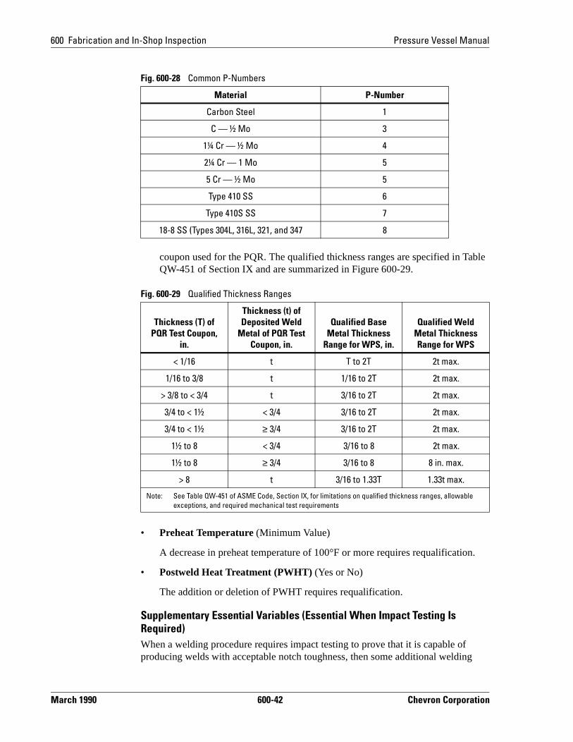
600 Fabrication and In-Shop Inspection Pressure Vessel Manual
n.
g
coupon used for the PQR. The qualified thickness ranges are specified in Table QW-451 of Section IX and are summarized in Figure 600-29.
• Preheat Temperature (Minimum Value)
A decrease in preheat temperature of 100°F or more requires requalificatio
• Postweld Heat Treatment (PWHT) (Yes or No)
The addition or deletion of PWHT requires requalification.
Supplementary Essential Variables (Essential When Impact Testing Is Required)When a welding procedure requires impact testing to prove that it is capable ofproducing welds with acceptable notch toughness, then some additional weldin
Fig. 600-28 Common P-Numbers
Material P-Number
Carbon Steel 1
C — ½ Mo 3
1¼ Cr — ½ Mo 4
2¼ Cr — 1 Mo 5
5 Cr — ½ Mo 5
Type 410 SS 6
Type 410S SS 7
18-8 SS (Types 304L, 316L, 321, and 347 8
Fig. 600-29 Qualified Thickness Ranges
Thickness (T) of PQR Test Coupon,
in.
Thickness (t) of Deposited Weld
Metal of PQR Test Coupon, in.
Qualified Base Metal Thickness
Range for WPS, in.
Qualified Weld Metal Thickness Range for WPS
< 1/16 t T to 2T 2t max.
1/16 to 3/8 t 1/16 to 2T 2t max.
> 3/8 to < 3/4 t 3/16 to 2T 2t max.
3/4 to < 1½ < 3/4 3/16 to 2T 2t max.
3/4 to < 1½ ≥ 3/4 3/16 to 2T 2t max.
1½ to 8 < 3/4 3/16 to 8 2t max.
1½ to 8 ≥ 3/4 3/16 to 8 8 in. max.
> 8 t 3/16 to 1.33T 1.33t max.
Note: See Table QW-451 of ASME Code, Section IX, for limitations on qualified thickness ranges, allowable exceptions, and required mechanical test requirements
March 1990 600-42 Chevron Corporation
Pressure Vessel Manual 600 Fabrication and In-Shop Inspection
o be ot -415 ow:
s lassi-
or e
ica- to
an sited
n.
tial re hey in
parameters (called “supplementary essential variables” by Section IX) must alsconsidered essential. When impact testing is not required, these variables are nconsidered essential. Supplementary essential variables are listed in Table QWof Section IX. The main supplementary essential variables are summarized bel
• Base Metal Subclassification (Group Number)
Various subclassifications of base metals with similar welding characteristicare grouped together under various “Group no.” categories which are subcfications of the P-number categories. (See Table QW-422 of Section IX.) A change in the “Group no.” requires requalification.
• Filler Metal Subclassification (AWS Classification)
A change in the AWS SFA filler metal classification number requires requalification.
• Welding Position (Vertical-Uphill Only); and if Vertical-Uphill, Welding Tech-nique (Weave Only)
A change from any position to vertical position—uphill progression welding;if qualified for vertical—uphill welding, a change from stringer bead to weavbead technique requires requalification.
• Number of Passes (Single Pass per Side Only)
A change from multi-pass per side to single pass per side requires requaliftion. Also, for automatic machine welding, a change from a single electrodemultiple electrodes, or vice versa, requires requalification.
• Heat Input (Current type, Polarity, Voltage Range, Current Range, Travel Speed, etc.)
A change in the type of current (AC vs DC) or polarity (straight vs reverse),increase in the heat input, or an increase in the volume of weld metal depoper unit length of weld requires requalification.
• Preheat Temperature Maximum Value
An increase in preheat temperature of 100°F or more requires requalificatio
• Postweld Heat Treatment (PWHT) Holding Time and Temperature Range
A change in the PWHT holding time and temperature range requires requalification.
Nonessential VariablesWelding parameters that are not classified as essential or supplementary essenvariables do not have to be specified by the WPS. These welding parameters acalled “nonessential variables” by Section IX. If they are included in the WPS, tmay be changed simply by revising the WPS. Nonessential variables are listedTable QW-415 of Section IX. The main nonessential variables are summarized below:
Chevron Corporation 600-43 March 1990
600 Fabrication and In-Shop Inspection Pressure Vessel Manual
.)
illet llet
l, it is e-ide-
ust d --27.)
il-s are
rning ce-ht be
-r
, e ould ly
• Electrode diameter
• Method of initial or interpass cleaning (brushing, grinding, chipping, etc.)
• Method of backgouging (grinding, arc-gouging, etc.)
• Groove design (V-Groove, U-Groove, Single Bevel, Double Bevel, Fillet, etc
Groove design is nonessential, except when the PQR is performed with a fweld coupon. Then the WPS is qualified only for non-pressure containing fiweld joints.
• Root gap
• Backing rings or backing strips
The use backing rings or backing strips is nonessential.
666 Welding Procedure ReviewThe degree of welding procedure review (if any) and who performs the review should be decided depending on the criticality of the pressure vessel. In generatypically not justified for a materials or welding engineer to review welding procdures for thin-wall carbon steel pressure vessels. An engineer following the gulines in this section can provide a satisfactory review. However, for thick-wall carbon steel, alloy steel, clad, and stainless steel vessels, you should have thewelding procedures reviewed by an individual who is familiar with ASME Code and Company requirements, such as a materials or welding engineer.
Pressure vessel fabricators normally submit qualified welding procedures to theCompany for review and approval before fabrication. Each welding procedure mconsist of a completed WPS (ASME form QW-482) and one (or more) completePQR (ASME form QW-483) which supports the WPS. (See Section 665.) (Examples of completed WPS and PQR forms are included in Figures 600-26 and 600
When reviewing welding procedures, it is beneficial to obtain a weld map (if avaable) from the pressure vessel fabricator which shows which welding procedureto be used for each weld joint. The weld map helps in making judgments concethe criticality and inspectability of weld joints made by the proposed welding produres. For example: Some less-desirable welding processes like FCAW-SS migdeemed acceptable for noncritical welds like insulation support ring welds, but would not be acceptable for longitudinal or circumferential weld seams.
When reviewing welding procedures, it should be clearly transmitted to the pressure vessel fabricator whether or not the welding procedures are acceptable fofabrication (either with or without revisions). This has historically been a problemand has resulted in significant delay and extra charges from fabricators becausapproval, rejection, or required revisions to welding procedures were not clearlytransmitted on the initial review. The following three categories of responses shtherefore be used for welding procedure review to avoid confusion about exactwhat is required:
March 1990 600-44 Chevron Corporation
Pressure Vessel Manual 600 Fabrication and In-Shop Inspection
e-
a in
i-
s tal PS. rtain
ot
cting to
ce-
alifi-ple-
lding
ing
erly
• “Acceptable as submitted”
This response notifies the vessel fabricator that the proposed welding procdure is approved as written, and that fabrication may begin.
• “Acceptable with the following exception(s)”
This response notifies the vessel fabricator that the welding procedure is approved if some revisions to nonessential variables, which do not require separate PQR (requalification), are made to the WPS. Fabrication may begupon completion of the revisions. These revisions can be reviewed by the Company inspector. Resubmittal to the engineer is not required.
For example: A FCAW-G welding procedure which does not specifically indcate electrode brand name or hydrogen content may be approved with the exception that low hydrogen electrodes must be used. Low hydrogen versunon-low hydrogen FCAW electrodes are not differentiated by AWS filler mespecifications and are therefore typically not specifically indicated by the WThe vessel fabricator should therefore add a note to the WPS requiring a cebrand name or maximum hydrogen content for the electrode and may thenbegin fabrication by that welding procedure.
• “Unacceptable because”
This response notifies the vessel fabricator that the welding procedure is napproved, and that fabrication may not begin until a revised (or separate) welding procedure has been reviewed and approved. The reason(s) for rejethe procedure should be clearly indicated in the transmittal to the fabricatoravoid their resubmittal of another unacceptable welding procedure.
This response should be used when the revisions required to make the produre acceptable involve changes to essential variables or supplementary essential variables (if applicable), therefore requiring a separate PQR (requcation). This response should also be used when essential variables or supmentary essential variables (if applicable) are incorrect or missing from thecompleted WPS or PQR forms.
Steps for Reviewing a Welding Procedure
Step 1.
Verify that each PQR referenced in each WPS is included in the package of weprocedures to be reviewed. Also insure that all pages of WPSs and PQRs are included. A good way to do this is to sort the documents and staple the supportPQR(s) to the applicable WPS.
If the supporting PQR(s) is missing from a WPS, then the WPS can not be propreviewed, and is therefore unacceptable.
Chevron Corporation 600-45 March 1990

600 Fabrication and In-Shop Inspection Pressure Vessel Manual
be
ith ers for
n re
Step 2.
Obtain a weld map (if available) from the fabricator to determine which WPSs are to be used for which weld joints. This will help in making judgments about whether or not a certain procedure is acceptable since the criticality and inspectability of various weld joints can differ significantly.
Step 3.
Verify that all of the essential variables and supplementary essential variables (if applicable) are included in the WPS. Some nonessential variables are usually also included, but do not have to be. See Section 665 above for a discussion of essential variables, supplementary essential variables, and nonessential variables.
If essential variables or supplementary essential variables (if applicable) are missing from a WPS, then the WPS can not be properly reviewed, and is therefore unaccept-able.
Step 4.
Verify that all of the essential variables and supplementary essential variables (if applicable) are included in the PQR(s), and that they agree with the variables included in the WPS. Nonessential variables in the PQR(s) do not have to agree with the variables in the WPS.
If essential variables or supplementary essential variables (if applicable) that are included in the supporting PQR(s) disagree with those included in the WPS, then the WPS is not qualified, and is therefore unacceptable.
Step 5.
Verify that all of the essential variables and supplementary essential variables (if applicable) that are included in the WPS agree with the actual requirements for the weld(s) to be performed.
This is the most important step. Frequently, the pressure vessel fabricator’s welding procedures are standardized. The WPSs include all essential variables required and are properly supported by PQRs, but the welding procedures do not agree with Company specifications or the requirements on the vessel drawings.
The checklist below summarizes the main items which should be verified. If the answer is “No” to any of the questions, then the pressure vessel welds will not performed with a qualified WPS. The WPS is therefore unacceptable.
For all welding procedures (essential variables):
Yes ____ No ____. Does the base metal (P-number) shown on the WPS agree wthe material of the pressure vessel as shown on the vessel drawings? (P-numbcommonly used base metal materials are included in Figure 600-28.)
Yes ____ No ____. Does the filler metal type (A-number and F-number) shown othe WPS agree with the type of filler metal which should be used for the pressu
March 1990 600-46 Chevron Corporation
Pressure Vessel Manual 600 Fabrication and In-Shop Inspection
pres-
th e
res- mate-
pres-
g the
vessel weld(s)? (Recommended filler metals for common pressure vessel materials and welding processes are summarized in Figure 600-19.)
Yes ____ No ____. Does the shielding gas composition shown on the WPS agree with the shielding gas composition which should be used for the pressure vessel weld(s)? (Recommended shielding gases for common materials and welding processes are included in Appendix A of the Welding Manual.)
Yes ____ No ____. For alloys with more than 3% Cr, does the WPS show the pres-ence, flow rate, and composition of a backing gas for single-sided welds? (Inert backing gas is required by the Company.) (See Section 662.)
Yes ____ No ____. For GMAW or FCAW welding processes, does the transfer mode (short circuiting transfer vs globular, spray, or pulsed transfer) which should be used for the actual pressure vessel weld(s) agree with that shown on the WPS? Note that short circuiting transfer is acceptable only for root passes in certain appli-cations. (See Section 661.)
Yes ____ No ____. Do the thicknesses of the actual pressure vessel components and weld(s) as shown on the vessel drawings fall within the thickness ranges shown by the WPS?
Yes ____ No ____. Is the minimum preheat temperature shown by the WPS no more than 100°F above that recommended for the vessel material? (See Figure600-22 for recommended preheat and interpass temperature limits for commonsure vessel materials.)
Yes ____ No ____. If PWHT is required for the pressure vessel weld(s), does theWPS show that PWHT is required?
Yes ____ No ____. If PWHT is not required for the pressure vessel weld(s), doesthe WPS show that PWHT is not required?
Applicable only for welding procedures which require impact testing (supplementary essential variables):
Yes ____ No ____. Does the base metal Group No. shown on the WPS agree withe material of the pressure vessel as shown on the vessel drawing? (See TablQW-422 of Section IX for group number categories)
Yes ____ No ____. Does the filler metal AWS Classification number (E-7018, E-6010, etc.) shown on the WPS agree with that which should be used for the psure vessel weld(s)? (Recommended filler metals for common pressure vesselrials and welding processes are summarized in Figure 600-19.)
Yes ____ No ____. Is the maximum preheat temperature shown by the WPS no more than 100°F below that recommended for the vessel material? (See Figure600-22 for recommended preheat and interpass temperature limits for commonsure vessel materials.)
Yes ____ No ____. If PWHT is required, does the PWHT temperature and holdintime recommended for the pressure vessel welds fall within the range shown on
Chevron Corporation 600-47 March 1990
600 Fabrication and In-Shop Inspection Pressure Vessel Manual
). g)
d,
e-
teel
n” s-
that
WPS? (See Figure 600-25 for recommended stress relief heat treatment temperature ranges and holding times for common pressure materials.)
Step 6.
Verify that any nonessential variables and supplementary essential variables (when impact testing is not required) that are included in the WPS agree with the require-ments for the weld(s) to be performed and that they agree with Company specifica-tion(s). The fabricator should be required to revise the WPS so that it gives proper instructions for the weld to be performed.
It is also good practice to require the fabricator to add additional nonessential vari-ables and supplementary essential variables to the WPS, when impact testing is not required to insure that important requirements in Company specification(s) are adhered to.
The WPS is the instruction sheet used by the welder making the pressure vessel weld(s). If the WPS does not contain the requirements included in Company specifi-cations, these requirements may not be adhered to when the pressure vessel welds are made.
Additions or changes to nonessential variables or supplementary essential variables when impact testing is not required simply requires a revision to the WPS docu-ment. A separate PQR (requalification) is not necessary. The revisions can even be short handwritten notes.
Examples of nonessential variables and supplementary essential variables, which should sometimes be added to the WPS even though not required by ASME Code, Section IX, are summarized below:
• Backgouging and backwelding requirements for single bevel groove weld(sOne-sided single bevel groove welds (without backgouging and backweldinshould only be accepted if welder access to the back of the weld is not practical.
• Requirement that permanent backing rings or backing strips are not allowewhen the WPS indicates use of backing material.
• Weld pass sequence diagram or chart for multiple pass weld(s). This requirment is especially important when multiple processes will be used for the weld(s).
• Requirement on FCAW-G welding procedure(s) for carbon steel and alloy svessels that only electrodes with low-hydrogen content or specific brand name(s) of carbon and alloy steel electrodes are acceptable. “Low-hydrogemeans less than 10 ml of diffusible hydrogen per 100 gm of typical as-depoited weld metal per the manufacturer's specifications, as measured by the mercury displacement or gas chromatograph methods per AWS A4.3. Notethis requirement is supplementary to (not covered by) applicable AWS fillermetal specifications.
March 1990 600-48 Chevron Corporation
Pressure Vessel Manual 600 Fabrication and In-Shop Inspection
re at, or ain sses
r
l nt
s
ss
”
that han
did ld
Requirement on GMAW welding procedure(s) using short-circuiting metal transfer that the WPS may be used only for root passes, and only if backgouged and back-welded. Short-arc GMAW processes are low heat input processes which are subject to lack-of-fusion defects. The process is acceptable only for root passes if back-gouged and backwelded. The process may also be allowed without backwelding for root passes of circumferential piping welds for fabricated nozzles and vessel internal piping, and for nonpressure containing vessel internals.
Requirement on SMAW welding procedure(s) for carbon steel material, which indi-cates cellulosic (i.e., E-6010) electrodes, that the WPS may be used only for the root pass of one-sided nonpressure containing attachment welds and circumferential piping joints and only when the base metal thickness is less than ¾ inch. Cellulosic electrodes such as E-6010 do not have low hydrogen content. They can therefocontribute to underbead cracking of welds with high restraint, inadequate prehehigh heat affected zone (HAZ) hardness. High restraint (joint thickness) is the mconcern with carbon steel pressure vessel materials. Therefore, for joint thicknebelow ¾ inch, cellulosic electrodes should be acceptable.
Step 7.
Verify that the mechanical test results shown in the PQR are acceptable.
Guided bend test results should say something like “satisfactory,” “passed,” or “acceptable.” In general, this means that they had no open defects exceeding 1/8 inch after being bent. (See QW-163 of Section IX for additional details.)
The “ultimate tensile stress” for tensile test specimens should be greater than oequal to the minimum tensile strength for the base material; (i.e., 70 ksi for SA-516-70 carbon steel material, 60 ksi for SA-106 and SA-285-C carbon steematerials). Exceptions and clarifications to this ultimate tensile stress requiremeare included in QW-153 of Section IX. It does not matter whether the specimenbreak in the weld metal or base metal.
When impact tests are required, “impact values” for toughness test specimens should meet or exceed the requirements of ASME Code, Figure UG-84.1, unleotherwise specified.
When the PQR is performed with a fillet-weld specimen, the “result-satisfactoryand the “penetration into parent metal” sections should be checked “yes.” This means that the specimen showed no signs of cracks or lack-of-penetration andthe sum of the visible porosity and inclusions on the fracture surface was less t3/8 inch. The “macro-results” section should say something like “satisfactory,” “passed,” or “acceptable.” This means that an etched cross section of the weldnot show signs of cracks, or linear defects exceeding 1/32 inch; and that the weprofile (concavity, convexity, etc.) was acceptable. (See QW-180 for additional details.)
Chevron Corporation 600-49 March 1990
600 Fabrication and In-Shop Inspection Pressure Vessel Manual
ess.
tion
nce al.
ders and
that lder
g of it
of e
the ance
667 Company Qualified Welding ProceduresMany welding procedures have been qualified within the Company, particularly by Chevron U.S.A. The welding procedures qualified by the Company may be used by any Company facility for the fabrication and repair of pressure vessels provided the welders are qualified in accordance with ASME Code, Section IX.
It is acceptable for Company qualified welding procedures to be used by individual contract welders doing work, directed and supervised by the Company (i.e., where they are in effect temporary Company employees) provided they have also passed the required welder performance qualifications tests per Section 668 below.
Contract welders who are not directed and supervised by the Company must provide their own qualified welding procedures, and may not use Company procedures without requalifying them.
A summary of the welding procedures that have been qualified by the Company are listed in Appendices B and C of the Welding Manual.
• Appendix B lists the welding procedures in numerical order by their WPS number.
• Appendix C lists the welding procedures by base material and welding proc
668 Welder Performance QualificationWelder performance qualification requirements should be per ASME Code, SecIX. They are different and less stringent than welding procedure qualification requirements discussed in Section 665 above. The purpose of Welder PerformaQualification is to determine the ability of the welder to deposit sound weld metSimilarly, Welding Operator Performance Qualification is used to determine themechanical ability of the welder to operate fully automatic or machine-guided equipment.
Performance Qualification TestsThe purpose of performance qualification tests is to determine the ability of weland welding operators. Each welder must be qualified for each welding processposition used in production welding. The performance qualification test is to beperformed in accordance with the variables outlined in a qualified WPS, exceptpreheat and postweld heat treatment requirements may be omitted. A blank weperformance qualification form is shown in Figure 600-30.
Welders and welding operators are generally required to pass mechanical testintest coupons for groove or fillet weld qualifications, but alternate rules also permradiography for testing of either groove weld test coupons, or a specified lengthproduction weld for most materials and welding processes. Mechanical tests arpreferred since radiography cannot detect planar defects.
Each pressure vessel manufacturer or contractor is responsible for conducting tests to qualify the performance of his welders and welding operators in accord
March 1990 600-50 Chevron Corporation
Pressure Vessel Manual 600 Fabrication and In-Shop Inspection
Fig. 600-30 Welder Performance Qualification Form Courtesy of the ASME
Chevron Corporation 600-51 March 1990

600 Fabrication and In-Shop Inspection Pressure Vessel Manual
hes hes t
t
erfor-
a-ary to ual-hich
mine
in .
with a qualified WPS. The manufacturer or contractor should be responsible for the full supervision and control of the tests.
ExpirationWelder qualifications have a specific time limit for which they are valid unless the welder or welding operator uses the process or processes for which he is qualified. Qualification expires in 3 months if a process is not used. If another welding process is used, the period can be extended up to 6 months. The fabricator is responsible for keeping records which can demonstrate that each welder is qualified by recent expe-rience.
Test CouponsThe test coupon material used for qualification does not have to be the same as designated in the WPS, and liberal substitutions are permitted. In general, P1 mate-rial (carbon steel) can be substituted for a wide range of materials, including low alloy steels, stainless steels, and nickel-base alloys.
Test coupons for welder qualifications are generally either plate or pipe. Groove qualification on pipe sizes 24 inches or less qualify for pipe sizes down to 2½ incin all positions. Plate groove qualifications also qualify pipe sizes down to 2½ incin the flat and horizontal positions. Groove weld qualifications also qualify for fillewelding but not vice versa. Test coupon thickness less than ¾ inch qualifies for welding on thicknesses up to two times the thickness of the test coupon, but tescoupon thicknesses 3/4 inch and over qualify for the maximum thickness to be welded.
Welder Performance VariablesVariables for welder performance qualification are categorized by Section IX asessential or nonessential. There are no supplementary essential variables for pmance qualification.
As with procedure qualification, changes in essential variables require requalifiction, while changes in nonessential variables do not. Therefore, it is not necessrequalify welders for a new job if the essential variables in the existing welder qification tests are not changed. However, it is important to note that variables ware essential for performance qualification are often nonessential variables for procedure qualification and vice versa. Section IX should be consulted to deterwhich variables are essential and which are not.
The variables for performance qualification are listed for each welding process QW-350 of Section IX and are defined in Article IV of Section IX (Welding Data)Welding operator qualifications are limited by the essential variables given in QW-360 of Section IX for each type of weld (fully automatic or machine-guidedwelding). A summary of essential variables for common welding processes is shown in Table QW-416 of Section IX.
March 1990 600-52 Chevron Corporation
Pressure Vessel Manual 600 Fabrication and In-Shop Inspection
ers
sing quip-
and
o fabri-rized ed n y
zzles.
g
al por-n the
n.
list l in
670 In-Shop Inspection
671 General CommentsShop inspection of virtually all pressure vessels except “off-the-shelf” air receivis warranted. Inspection at the fabrication plant is normally done by the Quality Assurance (QA) section of Purchasing, or by an inspector contracted by PurchaQA to inspect the vessel. The purpose of shop inspection is to ensure that the ement meets specification and order requirements, displays good workmanship,is free of significant damage or defects.
ASME Code uses the term “Authorized Inspector” to describe the inspector whworks for a state, municipality, or insurance company and must be used by thecator to inspect the vessel and sign the Manufacturer's Data Report. The AuthoInspector is not the same shop inspector that the Company uses. The AuthorizInspector's responsibility is to verify that the vessel is designed and fabricated iaccordance with ASME Code but he has no interest in and does not check manthings of interest to the Company, such as the following:
1. Dimensions or orientations (except for diameter and thickness).
2. Presence of all required nozzles or internals; plumbness/squareness of no
3. Limitations or restrictions in Company specifications on materials or weldinprocesses that are beyond ASME Code requirements.
4. Special construction details in Company specifications that exceed ASME Code requirements.
5. Inspection or testing requirements in Company specifications that exceed ASME Code minimums.
672 Degree of InspectionFigure 600-31 shows degrees of inspection for pressure vessels ranging from asingle inspection visit to resident inspection. The visits are listed in chronologicsequence. Degrees of inspection are listed generally in accordance with the imtance of the visit. Purchasing QA usually establishes the visits required based ospecifics of an order, but the job engineer can always participate in this decisio
Figure 600-32 shows rough guidelines for choosing the appropriate degree of inspection. Figure 600-31 defines the basic purpose for each visit but does not all of the tasks that the Company inspector is required to complete during thesevisits (see Section 673.) Degree 4 is the recommended minimum for any vesse
Chevron Corporation 600-53 March 1990

600 Fabrication and In-Shop Inspection Pressure Vessel Manual
hydrocarbon or critical service. Visits for purposes in addition to those listed can of course be added to cover any special concerns.
March 1990 600-54 Chevron Corporation
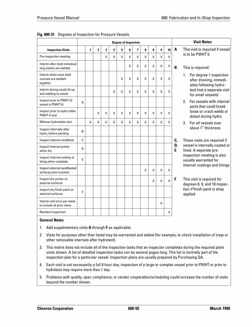
Pressure Vessel Manual 600 Fabrication and In-Shop Inspection
Fig. 600-31 Degrees of Inspection for Pressure Vessels
Degree of Inspection Visit Notes
Inspection Visits 1 2 3 4 5 6 7 8 8 9 10 A This visit is required if vessel is to be PWHT’dPre-inspection meeting X X X X X X X X X
Interim after most individual long seams are welded
X X X X X X B This is required:
Interim when most shell courses are welded together
X X X X X X X1. For degree 1 inspection
after draining, immedi-ately following hydro-test (not a separate visit for small vessels)
2. For vessels with internal parts that could break loose or crack welds or distort during hydro
3. For all vessels over about 1” thickness
Interim during nozzle fit-up and welding to vessel
X X X X X X X X
Inspect prior to PWHT (if vessel is PWHT’d)
A
Inspect prior to hydro (after PWHT if any)
X X X X X X X X X X
Witness hydrostatic test X X X X X X X X X X X
Inspect internally after hydro, before painting
B
Inspect internal sandblast C C, D, E
These visits are required if vessel is internally coated or lined. A separate pre-inspection meeting is also usually warranted for internal coatings and linings
Inspect internal primer when dry
D
Inspect internal coating or lining when complete
E
Inspect external sandblasted surfaces prior to primer
X X X X
Inspect dry primer on external surfaces
X X X F This visit is required for degrees 8, 9, and 10 inspec-tion if finish paint is shop applied
Inspect dry finish paint on external surfaces F
Interim visit once per week to include all prior items
X
Resident inspection X
General Notes
1. Add supplementary visits A through F as applicable.
2. Visits for purposes other than listed may be warranted and added (for example, to check installation of trays or other removable internals after hydrotest).
3. This matrix does not include all of the inspection tasks that an inspector completes during the required plant visits shown. A list of detailed inspection tasks can be several pages long. This list is normally part of the inspection plan for a particular vessel. Inspection plans are usually prepared by Purchasing QA.
4. Each visit is not necessarily a full 8 hour day; inspection of a large or complex vessel prior to PWHT or prior to hydrotest may require more than 1 day.
5. Problems with quality, spec compliance, or vendor cooperation/scheduling could increase the number of visits beyond the number shown.
Chevron Corporation 600-55 March 1990
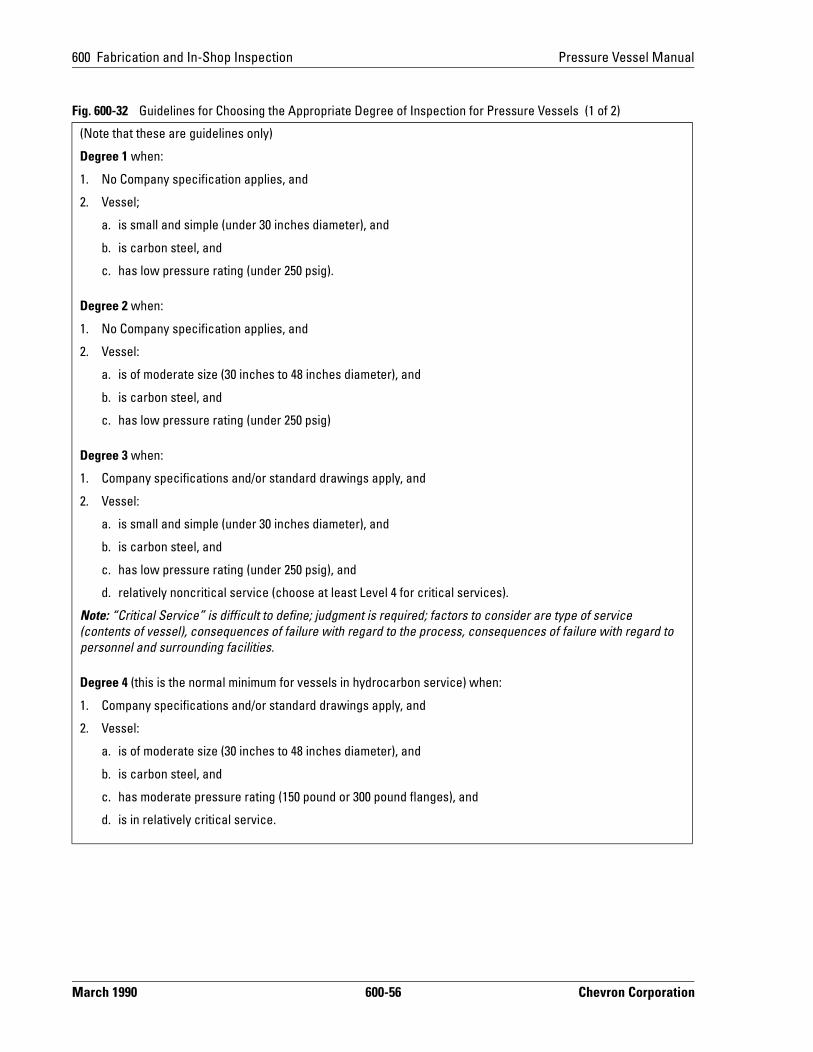
600 Fabrication and In-Shop Inspection Pressure Vessel Manual
Fig. 600-32 Guidelines for Choosing the Appropriate Degree of Inspection for Pressure Vessels (1 of 2)
(Note that these are guidelines only)
Degree 1 when:
1. No Company specification applies, and
2. Vessel;
a. is small and simple (under 30 inches diameter), and
b. is carbon steel, and
c. has low pressure rating (under 250 psig).
Degree 2 when:
1. No Company specification applies, and
2. Vessel:
a. is of moderate size (30 inches to 48 inches diameter), and
b. is carbon steel, and
c. has low pressure rating (under 250 psig)
Degree 3 when:
1. Company specifications and/or standard drawings apply, and
2. Vessel:
a. is small and simple (under 30 inches diameter), and
b. is carbon steel, and
c. has low pressure rating (under 250 psig), and
d. relatively noncritical service (choose at least Level 4 for critical services).
Note: “Critical Service” is difficult to define; judgment is required; factors to consider are type of service (contents of vessel), consequences of failure with regard to the process, consequences of failure with regard to personnel and surrounding facilities.
Degree 4 (this is the normal minimum for vessels in hydrocarbon service) when:
1. Company specifications and/or standard drawings apply, and
2. Vessel:
a. is of moderate size (30 inches to 48 inches diameter), and
b. is carbon steel, and
c. has moderate pressure rating (150 pound or 300 pound flanges), and
d. is in relatively critical service.
March 1990 600-56 Chevron Corporation
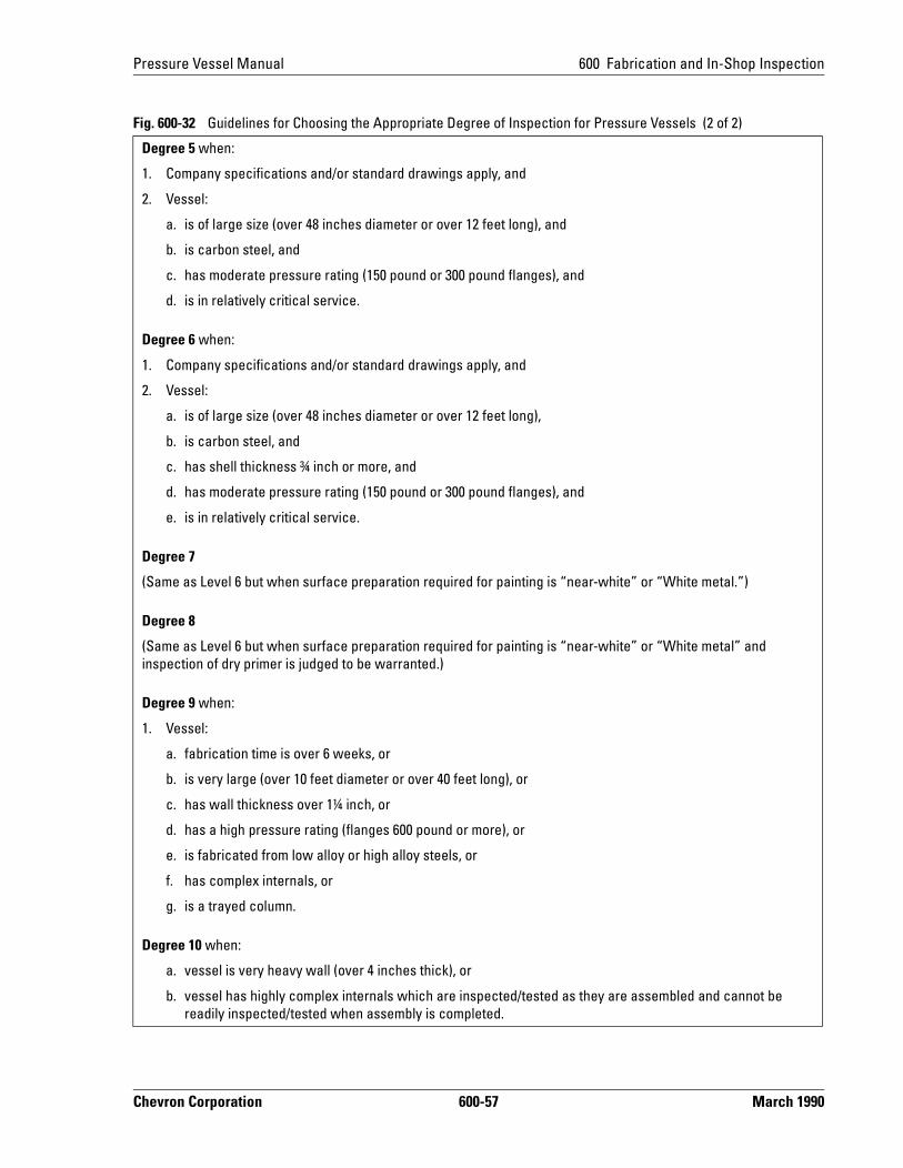
Pressure Vessel Manual 600 Fabrication and In-Shop Inspection
Degree 5 when:
1. Company specifications and/or standard drawings apply, and
2. Vessel:
a. is of large size (over 48 inches diameter or over 12 feet long), and
b. is carbon steel, and
c. has moderate pressure rating (150 pound or 300 pound flanges), and
d. is in relatively critical service.
Degree 6 when:
1. Company specifications and/or standard drawings apply, and
2. Vessel:
a. is of large size (over 48 inches diameter or over 12 feet long),
b. is carbon steel, and
c. has shell thickness ¾ inch or more, and
d. has moderate pressure rating (150 pound or 300 pound flanges), and
e. is in relatively critical service.
Degree 7
(Same as Level 6 but when surface preparation required for painting is “near-white” or “White metal.”)
Degree 8
(Same as Level 6 but when surface preparation required for painting is “near-white” or “White metal” and inspection of dry primer is judged to be warranted.)
Degree 9 when:
1. Vessel:
a. fabrication time is over 6 weeks, or
b. is very large (over 10 feet diameter or over 40 feet long), or
c. has wall thickness over 1¼ inch, or
d. has a high pressure rating (flanges 600 pound or more), or
e. is fabricated from low alloy or high alloy steels, or
f. has complex internals, or
g. is a trayed column.
Degree 10 when:
a. vessel is very heavy wall (over 4 inches thick), or
b. vessel has highly complex internals which are inspected/tested as they are assembled and cannot be readily inspected/tested when assembly is completed.
Fig. 600-32 Guidelines for Choosing the Appropriate Degree of Inspection for Pressure Vessels (2 of 2)
Chevron Corporation 600-57 March 1990

600 Fabrication and In-Shop Inspection Pressure Vessel Manual
mi-
hen raw-ons 7
d in
ting,
673 Inspection TasksFigure 600-31 does not list all of the tasks the Company inspector is required to complete during the plant visits. These tasks are normally listed in an inspection plan prepared by Purchasing QA. The tasks listed in the inspection plan can be several pages long. Some of the principal tasks are:
1. Verification that welding procedures and welders are qualified per ASME Code.
2. Review of material test reports for principal vessel parts and verification that vessel parts are traceable to material test reports.
3. Verification that welding procedures and preheat requirements are being followed.
4. Visual inspection of all welds for flaws, contour, size, and reinforcement.
5. Reading all radiographs (“x-rays”) and witnessing other nondestructive exanation (NDE) if required.
6. Complete dimensional and orientation check against Company drawings (wthey exist and are kept up-to-date) or against Company reviewed vendor dings. (It is prudent to include tolerances on vessel dimensions and orientatias part of the purchase order; Standard Drawings GA-C1266 and GA-C126are examples of typical tolerances on vessels. These drawings are includethis manual.)
7. Verification that all nozzles are present, and that they are of correct size, raand material.
8. Verification that internals are dimensionally correct and of the required material.
9. Review of Manufacturer's Data Report to verify that all entries are correct.
March 1990 600-58 Chevron Corporation
Related Documents