497 Check / Pilot Controlled Check Valves Check/Pilot Controlled Check Valves 25 (3630) 498 504 25 (3630) 02 03 06 10 10 16 24 03 06 10 10 16 03 06 10 2000 5000 200 500 100 50 20 10 5 2 1 1000 L /min U.S.GPM .3 .5 1 2 10 50 100 200 500 1000 20 5 Max. Operating Pressure MPa (PSI) Graphic Symbols Page Valve Type Check Valves In-Line (CIT) Right Angle (CRT/CRG) Flanged Connection(CP F) Threaded Connection(CP T) Sub-plate Mounting(CP G) Right Angle, Flanged Connection (CRF) Pilot Operated Check Valves

Welcome message from author
This document is posted to help you gain knowledge. Please leave a comment to let me know what you think about it! Share it to your friends and learn new things together.
Transcript
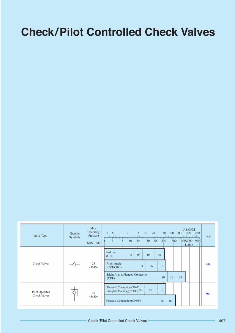
497Check/Pilot Controlled Check Valves
Check/Pilot Controlled Check Valves
25(3630)
498
50425(3630)
02 03 06 10
10 16 24
03 06 10
10 16
03 06 10
2000 5000200 500100502010521 1000L/min
U.S.GPM.3 .5 1 2 10 50 100 200 500 1000205
Max.OperatingPressure
MPa (PSI)
GraphicSymbols PageValve Type
Check Valves
In-Line(CIT)
Right Angle(CRT/CRG)
Flanged Connection(CP F)
Threaded Connection(CP T)Sub-plate Mounting(CP G)
Right Angle, Flanged Connection(CRF)
Pilot OperatedCheck Valves
Check/Pilot Controlled Check Valves498
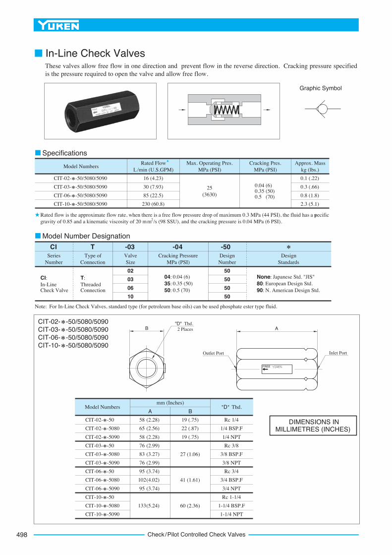
■ In-Line Check ValvesThese valves allow free flow in one direction and prevent flow in the reverse direction. Cracking pressure specified is the pressure required to open the valve and allow free flow.
Graphic Symbol
Max. Operating Pres. MPa (PSI)
Model NumbersApprox. Mass
kg (lbs.)
0.1 (.22)
0.3 (.66)
0.8 (1.8)
2.3 (5.1)
Cracking Pres. MPa (PSI)
Rated Flow L /min (U.S.GPM)
CIT-02- -50/5080/5090
CIT-03- -50/5080/5090
CIT-06- -50/5080/5090
CIT-10- -50/5080/5090
0.04 (6) 0.35 (50) 0.5 (70)
25(3630)
16 (4.23)
30 (7.93)
85 (22.5)
230 (60.8)
CI T -04 -50Series
NumberType of
ConnectionValveSize
DesignNumber
DesignStandards
-03
02
03
06
10
50
50
50
50
None: Japanese Std. "JIS"80: European Design Std.90: N. American Design Std.
04: 0.04 (6)35: 0.35 (50)50: 0.5 (70)
T:ThreadedConnection
CI:In-LineCheck Valve
Cracking Pressure MPa (PSI)
Model Number Designation
Specifications
Note: For In-Line Check Valves, standard type (for petroleum base oils) can be used phosphate ester type fluid.
Rated flow is the approximate flow rate, when there is a free flow pressure drop of maximum 0.3 MPa (44 PSI), the fluid has a specific2gravity of 0.85 and a kinematic viscosity of 20 mm /s (98 SSU), and the cracking pressure is 0.04 MPa (6 PSI).
Model Numbers "D" Thd.mm (Inches)
A B
CIT-02- -50
CIT-02- -5080
CIT-02- -5090
CIT-03- -50
CIT-03- -5080
CIT-03- -5090
CIT-06- -50
CIT-06- -5080
CIT-06- -5090
CIT-10- -50
CIT-10- -5080
CIT-10- -5090
Rc 1/4
1/4 BSP.F
1/4 NPT
Rc 3/8
3/8 BSP.F
3/8 NPT
Rc 3/4
3/4 BSP.F
3/4 NPT
Rc 1-1/4
1-1/4 BSP.F
1-1/4 NPT
19 (.75)
22 (.87)
19 (.75)
27 (1.06)
41 (1.61)
60 (2.36)
58
65
58
76
83
76
95
102
95
(2.28)
(2.56)
(2.28)
(2.99)
(3.27)
(2.99)
(3.74)
(4.02)
(3.74)
133(5.24)
FREE
AB"D" Thd. 2 Places
Outlet Port Inlet Port
CIT-02- -50/5080/5090CIT-03- -50/5080/5090CIT-06- -50/5080/5090CIT-10- -50/5080/5090
DIMENSIONS IN MILLIMETRES (INCHES)
499
DIRECTIONAL CONTROLS
In-L
ine
Ch
eck
Val
ves
E
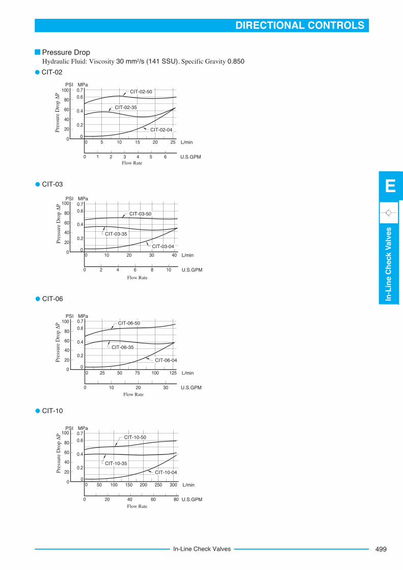
In-Line Check Valves
Hydraulic Fluid: Viscosity 30 mm2/s (141 SSU), Specific Gravity 0.850Pressure Drop
CIT-02
0 105 15 20 25 L/min0
0.4
PSI
40
80
Pres
sure
Dro
p Δ
P
20
0
0.2
0.6
60
0 21 3 4 5 U.S.GPM6Flow Rate
0.7MPa
100 CIT-02-50
CIT-02-35
CIT-02-04
0 10 20 30 40 L/min
0 2 4 U.S.GPM6
Flow Rate
108
0
0.4
PSI
40
80
Pres
sure
Dro
p Δ
P
20
0
0.2
0.6
60
0.7MPa
100
CIT-03-04
CIT-03-35
CIT-03-50
CIT-03
0
0.4
PSI
40
80
Pres
sure
Dro
p Δ
P
20
0
0.2
0.6
60
0.7MPa
100
0 25 50 100 L/min
0 10 20 U.S.GPM30Flow Rate
75 125
CIT-06-50
CIT-06-35
CIT-06-04
CIT-06
0 50 100 200 300 L/min
0 20 40 U.S.GPM60Flow Rate
80
0
0.4
PSI
40
80
Pres
sure
Dro
p Δ
P
20
0
0.2
0.6
60
0.7MPa
100
150 250
CIT-10-35
CIT-10-04
CIT-10-50
CIT-10
500 Right Angle Check Valves
CR T -04 -50Series
NumberType of
ConnectionValveSize
DesignNumber
DesignStandards
-03
03
06
10
03
06
10
04:
35:
50:
04:
35:
50:
None: Japanese Std. "JIS"& European Design Std.
90: N. American Design Std.
T:ThreadedConnection
Cracking Pressure MPa (PSI)
Model NumbersType of Connection
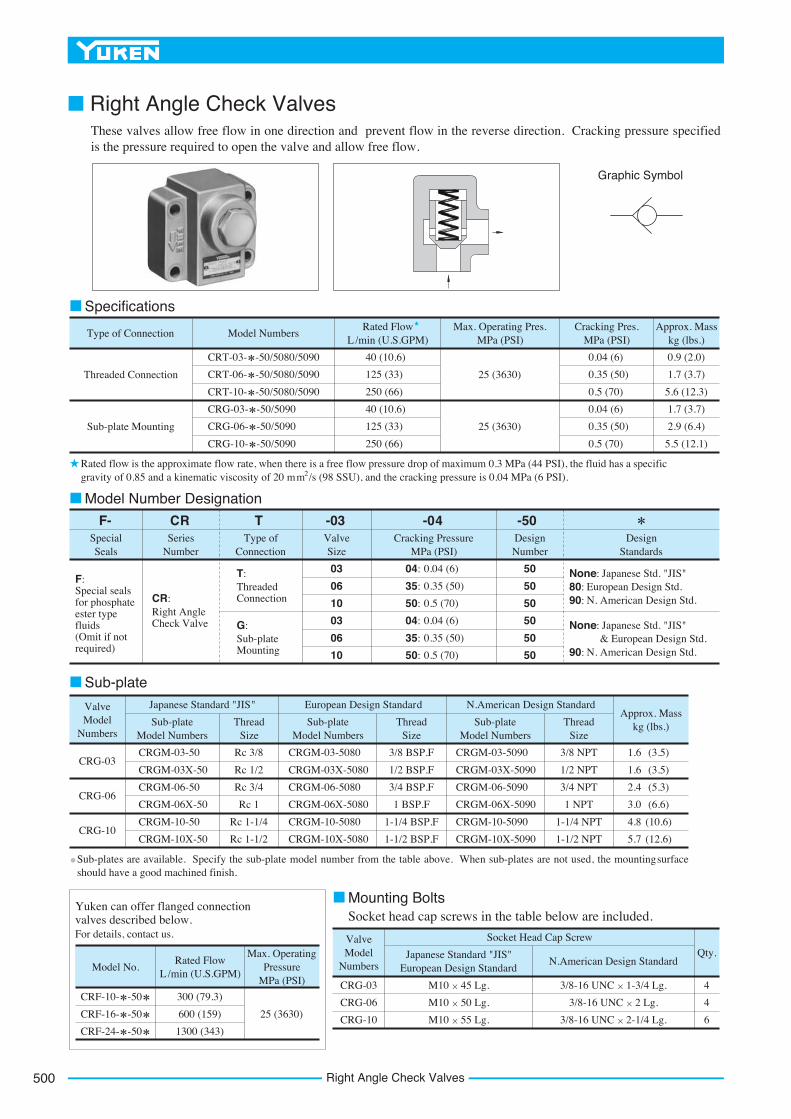
CRT-03- -50/5080/5090
CRT-06- -50/5080/5090
CRT-10- -50/5080/5090
CRG-03- -50/5090
CRG-06- -50/5090
CRG-10- -50/5090
Max. Operating Pres. MPa (PSI)
Approx. Mass kg (lbs.)
Cracking Pres. MPa (PSI)
Rated Flow L /min (U.S.GPM)
0.9 (2.0)
1.7 (3.7)
5.6 (12.3)
1.7 (3.7)
2.9 (6.4)
5.5 (12.1)
25 (3630)
0.04 (6)
0.35 (50)
0.5 (70)
0.04 (6)
0.35 (50)
0.5 (70)
25 (3630)
40 (10.6)
125 (33)
250 (66)
40 (10.6)
125 (33)
250 (66)
Threaded Connection
Sub-plate Mounting
50
50
50
50
50
50
None: Japanese Std. "JIS"European Design Std.
90: N. American Design Std.80:
F-SpecialSeals
G:Sub-plateMounting
CR:Right Angle Check Valve
F:Special seals for phosphate ester type fluids(Omit if not required)
0.04 (6)
0.35 (50)
0.5 (70)
0.04 (6)
0.35 (50)
0.5 (70)
ValveModel
Numbers
Socket Head Cap Screw
Qty.Japanese Standard "JIS" European Design Standard
N.American Design Standard
CRG-03
CRG-06
CRG-10
4
4
6
M10 45 Lg.
M10 50 Lg.
M10 55 Lg.
3/8-16 UNC 1-3/4 Lg.
3/8-16 UNC 2 Lg.
3/8-16 UNC 2-1/4 Lg.
Approx. Mass kg (lbs.)
Japanese Standard "JIS" European Design Standard N.American Design StandardValveModel
NumbersSub-plate
Model NumbersSub-plate
Model NumbersSub-plate
Model NumbersThread
SizeThread
SizeThread
Size
CRG-03
CRG-06
CRG-10
(3.5)
(3.5)
(5.3)
(6.6)
(10.6)
(12.6)
1.6
1.6
2.4
3.0
4.8
5.7
3/8 NPT
1/2 NPT
3/4 NPT
1 NPT
1-1/4 NPT
1-1/2 NPT
3/8 BSP.F
1/2 BSP.F
3/4 BSP.F
1 BSP.F
1-1/4 BSP.F
1-1/2 BSP.F
Rc 3/8
Rc 1/2
Rc 3/4
Rc 1
Rc 1-1/4
Rc 1-1/2
CRGM-03-50
CRGM-03X-50
CRGM-06-50
CRGM-06X-50
CRGM-10-50
CRGM-10X-50
CRGM-03-5080
CRGM-03X-5080
CRGM-06-5080
CRGM-06X-5080
CRGM-10-5080
CRGM-10X-5080
CRGM-03-5090
CRGM-03X-5090
CRGM-06-5090
CRGM-06X-5090
CRGM-10-5090
CRGM-10X-5090
Model No.Rated Flow
L /min (U.S.GPM)
Max. Operating Pressure
MPa (PSI)
CRF-10- -50
CRF-16- -50
CRF-24- -50
300 (79.3)
600 (159)
1300 (343)
25 (3630)
Model Number Designation
Specifications
Rated flow is the approximate flow rate, when there is a free flow pressure drop of maximum 0.3 MPa (44 PSI), the fluid has a specific2gravity of 0.85 and a kinematic viscosity of 20 mm /s (98 SSU), and the cracking pressure is 0.04 MPa (6 PSI).
Sub-plate
Mounting BoltsSocket head cap screws in the table below are included.
Yuken can offer flanged connection valves described below.For details, contact us.
Sub-plates are available. Specify the sub-plate model number from the table above. When sub-plates are not used, the mounting surface should have a good machined finish.
■ Right Angle Check ValvesThese valves allow free flow in one direction and prevent flow in the reverse direction. Cracking pressure specified is the pressure required to open the valve and allow free flow.
Graphic Symbol
501
DIRECTIONAL CONTROLS
Rig
ht
An
gle
Ch
eck
Val
ves
E
Right Angle Check Valves
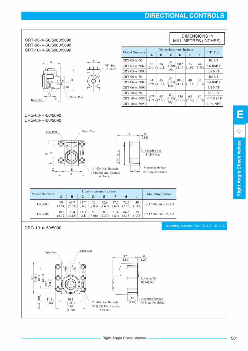
Mounting surface: ISO 5781-AJ-10-2-A
CRT-03- -50
CRT-03- -5080
CRT-03- -5090
CRT-06- -50
CRT-06- -5080
CRT-06- -5090
CRT-10- -50
CRT-10- -5080
CRT-10- -5090
Rc 3/8
3/8 BSP.F
3/8 NPT
Rc 3/4
3/4 BSP.F
3/4 NPT
Rc 1-1/4
1-1/4 BSP.F
1-1/4 NPT
Model Numbers "H" Thd.Dimensions mm (Inches)
FA B D E
62(2.44)
36(1.42)
38(1.50)Dia
80.5(3.17)
33(1.30)
44(1.73)
45(1.77)
54(2.13)Dia.
104.5(4.11)
49(1.93)
54(2.13)
65(2.56)
80(3.15)SQ.
130(5.12)
65(2.56)
80(3.15)
74(2.91)
107(4.21)
ecafruS gnitnuoMsrebmuN ledoMDimensions mm (Inches)
FA B C D E H J
ISO 5781-AG-06-2-A
ISO 5781-AH-08-2-A
CRG-03
CRG-06
90(3.54)
102(4.02)
79.4(3.13)
66.7(2.63)
11.3(.44)
11.7(.46)
93(3.66)
72(2.83)
60.3(2.37)
42.9(1.69)
21.4(.84)
17.5(.69)
84.5(3.33)
72.5(2.85)
35(1.38)
30(1.18)
E
FR
EE
FR
EE
A F
BC
C D
"H" Thd. 2 Places
Outlet PortInlet Port
D EF
B
A
J
H 6
C
Outlet PortInlet Port
Mounting Surface
(O-Rings Furnished)
Locating Pin 6(.24) Dia.
(.24)
Outlet PortInlet Port
11(.43) Dia. Through
17.5(.69) Dia. Spotface 6 Places
Mounting Surface (O-Rings Furnished)
Locating Pin 6(.24) Dia.
96.8(3.81)120
(4.72)
11.6(.46)
42.1
(1.6
6)84.1
(3.3
1)
123
(4.8
4)20
.3 (
.80)
97(3.82)
6(.24)
40(1.57)
11(.43) Dia. Through
17.5(.69) Dia. Spotface 4 Places
CRT-03- -50/5080/5090CRT-06- -50/5080/5090CRT-10- -50/5080/5090
DIMENSIONS IN MILLIMETRES (INCHES)
CRG-03- -50/5090CRG-06- -50/5090
CRG-10- -50/5090
C
502 Right Angle Check Valves
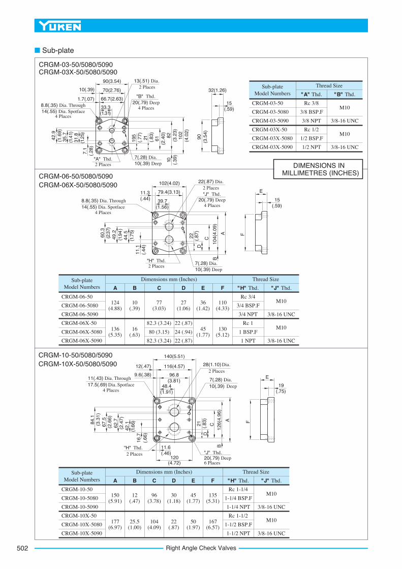
CRGM-03-50
CRGM-03-5080
CRGM-03-5090
CRGM-03X-50
CRGM-03X-5080
CRGM-03X-5090
Sub-plateModel Numbers
Thread Size
"A" Thd. "B" Thd.
Rc 3/8
3/8 BSP.F
3/8 NPT
Rc 1/2
1/2 BSP.F
1/2 NPT
M10
3/8-16 UNC
3/8-16 UNC
M10
82.3 (3.24)
80 (3.15)
82.3 (3.24)
22 (.87)
24 (.94)
22 (.87)
"H" Thd. "J" Thd.
Rc 3/4
3/4 BSP.F
3/4 NPT
Rc 1
1 BSP.F
1 NPT
M10
3/8-16 UNC
3/8-16 UNC
M10
FEDCBA
Thread SizeDimensions mm (Inches)Sub-plateModel Numbers
CRGM-06-50
CRGM-06-5080
CRGM-06-5090
CRGM-06X-50
CRGM-06X-5080
CRGM-06X-5090
124(4.88)
10(.39)
77(3.03)
27(1.06)
36(1.42)
110(4.33)
136(5.35)
16(.63)
45(1.77)
130(5.12)
"H" Thd. "J" Thd.
Rc 1-1/4
1-1/4 BSP.F
1-1/4 NPT
Rc 1-1/2
1-1/2 BSP.F
1-1/2 NPT
M10
3/8-16 UNC
3/8-16 UNC
M10
FEDCBA
Thread SizeDimensions mm (Inches)Sub-plateModel Numbers
CRGM-10-50
CRGM-10-5080
CRGM-10-5090
CRGM-10X-50
CRGM-10X-5080
CRGM-10X-5090
150(5.91)
177(6.97)
12(.47)
25.5(1.00)
96(3.78)
104(4.09)
30(1.18)
22(.87)
45(1.77)
50(1.97)
135(5.31)
167(6.57)
90(3.54)
70(2.76)
33.3(1.31)
66.7(2.63)
7.1
(.28
)
(1.2
5)31
.8(1
.41)
35.7
42.9
(1.6
9)
19.5
(.77
)21 (.83
)61
(2.4
0) 82(3
.23)
102
(4.0
2)
10 (.39
)
90(3
.54)
15(.59)
32(1.26)
13(.51) Dia. 2 Places
"B" Thd. 20(.79) Deep
4 Places8.8(.35) Dia. Through 14(.55) Dia. Spotface
4 Places
10(.39)
1.7(.07)
"A" Thd. 2 Places
7(.28) Dia. 10(.39) Deep
102(4.02)
79.4(3.13)11.3(.44) 39.7
(1.56)8.8(.35) Dia. Through 14(.55) Dia. Spotface
4 Places
22(.87) Dia. 2 Places"J" Thd.
20(.79) Deep 4 Places
11.1
(.44
)
(1.7
5)44
.5(1
.94
)49
.2(2
.37)
60.3
22 (.87
)D
C
104(
4.09
)
A
B
F
15(.59)
E
7(.28) Dia. 10(.39) Deep
"H" Thd. 2 Places
F
19(.75)
E
28(1.10) Dia. 2 Places
A
(.66
)16
.7(1
.66)
42.1
(2.4
7)62
.7(2
.66)
67.5
(3.3
1)84
.1
11.6(.46)
120(4.72)
48.4(1.91)
96.8(3.81)
140(5.51)
116(4.57)
7(.28) Dia. 10(.39) Deep
"H" Thd. 2 Places
11(.43) Dia. Through 17.5(.69) Dia. Spotface
4 Places
12(.47)
9.6(.38)
"J" Thd. 20(.79) Deep 6 Places
B
DC(.83
)21
126(
4.96
)
DIMENSIONS IN MILLIMETRES (INCHES)
CRGM-03-50/5080/5090CRGM-03X-50/5080/5090
CRGM-06-50/5080/5090CRGM-06X-50/5080/5090
CRGM-10-50/5080/5090CRGM-10X-50/5080/5090
■ Sub-plate
503
DIRECTIONAL CONTROLS
Rig
ht
An
gle
Ch
eck
Val
ves
E
Right Angle Check Valves
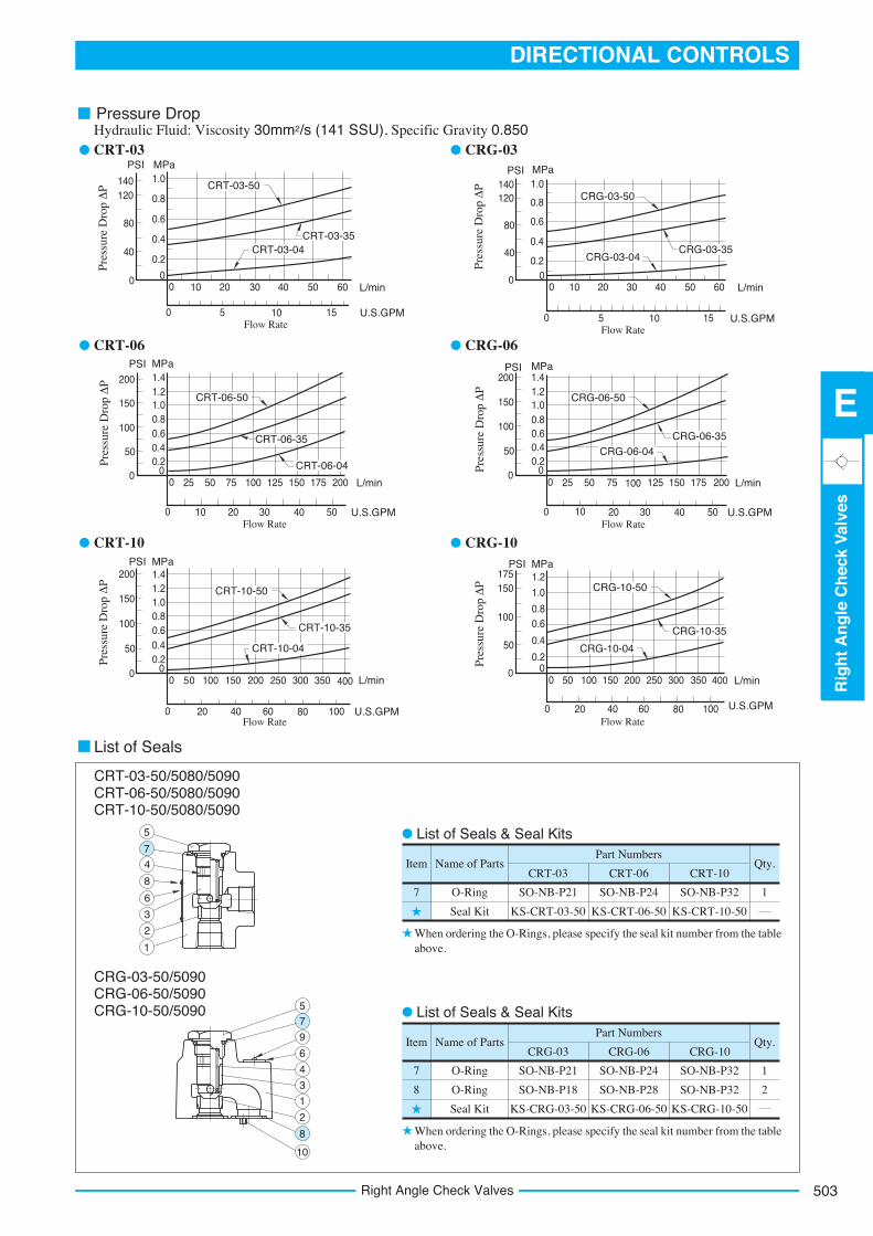
Name of Parts .ytQmetICRT-03 CRT-06 CRT-10
Part Numbers
7 O-Ring
Seal Kit
SO-NB-P21
KS-CRT-03-50
SO-NB-P24
KS-CRT-06-50
SO-NB-P32
KS-CRT-10-50
1
Name of Parts .ytQmetICRG-03 CRG-06 CRG-10
Part Numbers
7
8
O-Ring
O-Ring
Seal Kit
SO-NB-P21
SO-NB-P18
KS-CRG-03-50
SO-NB-P24
SO-NB-P28
KS-CRG-06-50
SO-NB-P32
SO-NB-P32
KS-CRG-10-50
1
2
10
8
2
1
3
4
6
9
75
1
2
3
6
8
4
7
5
0 10 20 L/min
0 5 U.S.GPMFlow Rate
30 40 50 60
1510
0
0.4
PSI
40
80
Pres
sure
Dro
p Δ
P
0
0.2
0.6
0.8
140 1.0
120
MPa
0 25 50 L/min
0 10 U.S.GPMFlow Rate
75 125 150 175
5040
100 200
20 30
0
0.4
PSI
50
100
Pres
sure
Dro
p Δ
P
00.2
0.60.8
200
1.0150
MPa
1.21.4
0 nim/L05
0 20 U.S.GPMFlow Rate
150
10080
100 200
40 60
0
0.4
PSI
50
100
Pres
sure
Dro
p Δ
P
00.2
0.60.8
200
1.0150
MPa
1.21.4
250 300 350 400
0 10 20 L/min
0 5 U.S.GPMFlow Rate
30 40 50 60
1510
0
0.4
PSI
40
80
Pres
sure
Dro
p Δ
P
0
0.2
0.6
0.8
140 1.0120
MPa
0 25 50 L/min
0 10 U.S.GPMFlow Rate
75 125 150 175
5040
100 200
20 30
0
0.4
PSI
50
100
Pres
sure
Dro
p Δ
P0
0.2
0.60.8
200
1.0150
MPa
1.21.4
0 50 L/min
0 20 U.S.GPM
Flow Rate
150
10080
100 200
40 60
0
0.4
PSI
50
100
Pres
sure
Dro
p Δ
P
0
0.2
0.60.8
175
1.0150
MPa1.2
250 300 350 400
CRG-03-50
CRG-03-35CRG-03-04
CRG-06-50
CRG-06-35CRG-06-04
CRG-10-50
CRG-10-35
CRG-10-04
CRT-10-50
CRT-10-35
CRT-10-04
CRT-06-50
CRT-06-35
CRT-06-04
CRT-03-50
CRT-03-35CRT-03-04
Hydraulic Fluid: Viscosity 30mm2/s (141 SSU), Specific Gravity 0.850CRT-03
CRT-06
CRT-10
CRG-03
CRG-06
CRG-10
List of Seals
CRT-03-50/5080/5090CRT-06-50/5080/5090CRT-10-50/5080/5090
CRG-03-50/5090CRG-06-50/5090CRG-10-50/5090
When ordering the O-Rings, please specify the seal kit number from the tableabove.
When ordering the O-Rings, please specify the seal kit number from the tableabove.
List of Seals & Seal Kits
List of Seals & Seal Kits
Pressure Drop
504 Pilot Operated Check Valves
Specifications
Model NumbersRated Flow
L /min (U.S.GPM)
CP F-10- - -50
CP F-16- - -50
Max. Operating Pressure
MPa (PSI)
250
600
(66)
(159)
25
25
(3630)
(3630)
ValveModel
Numbers
Socket Head Cap Screw
Qty.Japanese Standard "JIS" & European Design Standard
N.AmericanDesign Standard
CP G-03
CP G-06
CP G-10
4
4
6
M10 45 Lg.
M10 50 Lg.
M10 55 Lg.
3/8-16 UNC 1-3/4 Lg.
3/8-16 UNC 2 Lg.
3/8-16 UNC 2-1/4 Lg.
CP T -04 -50Series
NumberType of
ConnectionValveSize
DesignNumber
DesignStandards
03Cracking Pres.
MPa (PSI)
F-SpecialSeals
-EDrain
Connection
03
06
10
03
06
10
50
50
50
50
50
50
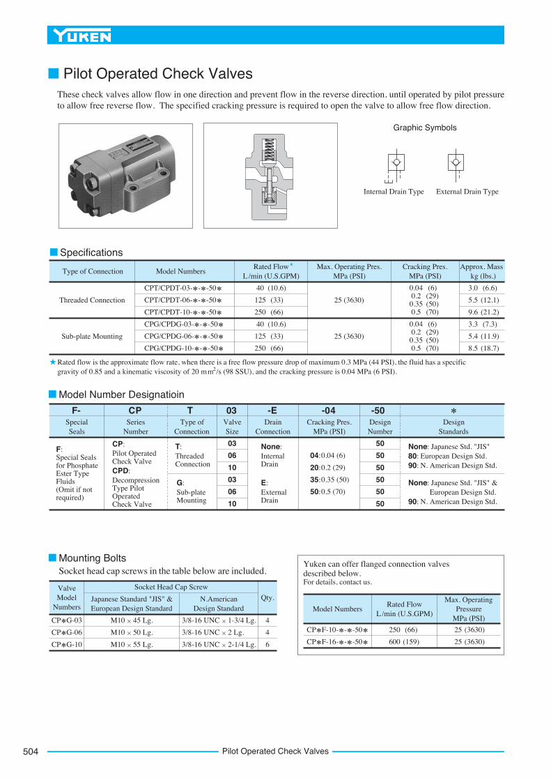
None: Japanese Std. "JIS"European Design Std.
90: N. American Design Std.80:
None: Japanese Std. "JIS" &European Design Std.
90: N. American Design Std.
T:ThreadedConnection
G:Sub-plateMounting
F:Special Seals for Phosphate Ester Type Fluids(Omit if not required)
CP:Pilot Operated Check ValveCPD:DecompressionType Pilot OperatedCheck Valve
04:
20:
35:
50:
0.04 (6)
0.2 (29)
0.35 (50)
0.5 (70)
None:InternalDrain
E:ExternalDrain
Threaded Connection
Model NumbersType of Connection
CPT/CPDT-03- - -50
CPT/CPDT-06- - -50
CPT/CPDT-10- - -50
CPG/CPDG-03- - -50
CPG/CPDG-06- - -50
CPG/CPDG-10- - -50
Max. Operating Pres. MPa (PSI)
Approx. Mass kg (lbs.)
Cracking Pres. MPa (PSI)
Rated Flow L /min (U.S.GPM)
25 (3630)
25 (3630)
40
125
250
40
125
250
Sub-plate Mounting
0.040.2
0.350.5
(6)(29)(50)(70)
0.040.2
0.350.5
(6)(29)(50)(70)
(10.6)
(33)
(66)
(10.6)
(33)
(66)
3.0
5.5
9.6
3.3
5.4
8.5
(6.6)
(12.1)
(21.2)
(7.3)
(11.9)
(18.7)
Yuken can offer flanged connection valves described below.For details, contact us.
Mounting BoltsSocket head cap screws in the table below are included.
Model Number Designatioin
Graphic Symbols
Internal Drain Type External Drain Type
Rated flow is the approximate flow rate, when there is a free flow pressure drop of maximum 0.3 MPa (44 PSI), the fluid has a specific2gravity of 0.85 and a kinematic viscosity of 20 mm /s (98 SSU), and the cracking pressure is 0.04 MPa (6 PSI).
These check valves allow flow in one direction and prevent flow in the reverse direction, until operated by pilot pressure to allow free reverse flow. The specified cracking pressure is required to open the valve to allow free flow direction.
■ Pilot Operated Check Valves
505
DIRECTIONAL CONTROLS
Pilo
tO
per
ated
Ch
eck
Val
ves
E
Pilot Operated Check Valves
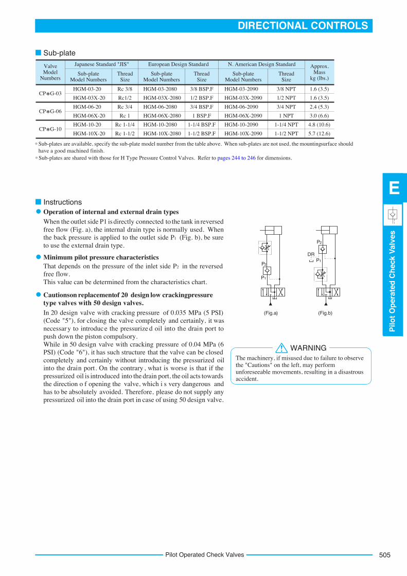
(Fig.a) (Fig.b)
P1
P2
P2
P1
DR
ValveModel
Numbers
Japanese Standard "JIS"
Sub-plateModel Numbers
ThreadSize
Sub-plateModel Numbers
ThreadSize
Sub-plateModel Numbers
Approx.Mass
kg (lbs.)Thread
Size
European Design Standard N. American Design Standard
CP G-03
CP G-06
CP G-10
1.6 (3.5)
1.6 (3.5)
2.4 (5.3)
3.0 (6.6)
4.8 (10.6)
5.7 (12.6)
Rc 3/8
Rc1/2
Rc 3/4
Rc 1
Rc 1-1/4
Rc 1-1/2
3/8 BSP.F
1/2 BSP.F
3/4 BSP.F
1 BSP.F
1-1/4 BSP.F
1-1/2 BSP.F
3/8 NPT
1/2 NPT
3/4 NPT
1 NPT
1-1/4 NPT
1-1/2 NPT
HGM-03-20
HGM-03X-20
HGM-06-20
HGM-06X-20
HGM-10-20
HGM-10X-20
HGM-03-2080
HGM-03X-2080
HGM-06-2080
HGM-06X-2080
HGM-10-2080
HGM-10X-2080
HGM-03-2090
HGM-03X-2090
HGM-06-2090
HGM-06X-2090
HGM-10-2090
HGM-10X-2090
Sub-plate
InstructionsOperation of internal and external drain typesWhen the outlet side P1 is directly connected to the tank in reversed free flow (Fig. a), the internal drain type is normally used. When the back pressure is applied to the outlet side P1 (Fig. b), be sure to use the external drain type.
Minimum pilot pressure characteristicsThat depends on the pressure of the inlet side P2 in the reversed free flow. This value can be determined from the characteristics chart.
Cautions on replacement of 20 design low cracking pressure.sevlav ngised 05 htiw sevlav epyt
In 20 design valve with cracking pressure of 0.035 MPa (5 PSI) (Code "5"), for closing the valve completely and certainly, it was necessar y to introduc e the pressurize d oil into the drain port to push down the piston compulsory. While in 50 design valve with cracking pressure of 0.04 MPa (6 PSI) (Code "6"), it has such structure that the valve can be closed completely and certainly without introducing the pressurized oil into the drain port. On the contrary , what is worse is that if the pressurized oil is introduced into the drain port, the oil acts towards the direction o f opening the valve, which i s very dangerous and has to be absolutely avoided. Therefore, please do not supply any pressurized oil into the drain port in case of using 50 design valve.
The machinery, if misused due to failure to observethe "Cautions" on the left, may perform unforeseeable movements, resulting in a disastrous accident.
WARNING
Sub-plates are available, specify the sub-plate model number from the table above. When sub-plates are not used, the mounting surface shouldhave a good machined finish.Sub-plates are shared with those for H Type Pressure Control Valves. Refer to pages 244 to 246 for dimensions.
506 Pilot Operated Check Valves
Model NumbersB
Dimensions mm (Inches)
C
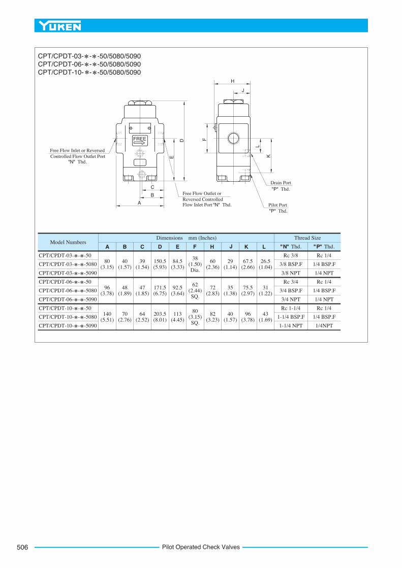
CPT/CPDT-03- - -50
CPT/CPDT-03- - -5080
CPT/CPDT-03- - -5090
CPT/CPDT-06- - -50
CPT/CPDT-06- - -5080
CPT/CPDT-06- - -5090
CPT/CPDT-10- - -50
CPT/CPDT-10- - -5080
CPT/CPDT-10- - -5090
D E F H K LA "N" Thd. "P" Thd.
Thread Size
Rc 3/8
3/8 BSP.F
3/8 NPT
Rc 3/4
3/4 BSP.F
3/4 NPT
Rc 1-1/4
1-1/4 BSP.F
1-1/4 NPT
Rc 1/4
1/4 BSP.F
1/4 NPT
Rc 1/4
1/4 BSP.F
1/4 NPT
Rc 1/4
1/4 BSP.F
1/4NPT
80(3.15)
40(1.57)
39(1.54)
150.5(5.93)
84.5(3.33)
38(1.50)Dia.
60(2.36)
29(1.14)
67.5(2.66)
26.5(1.04)
96(3.78)
48(1.89)
47(1.85)
171.5(6.75)
92.5(3.64)
62(2.44)SQ.
72(2.83)
35(1.38)
75.5(2.97)
31(1.22)
140(5.51)
70(2.76)
64(2.52)
203.5(8.01)
113(4.45)
80(3.15)SQ.
82(3.23)
40(1.57)
96(3.78)
43(1.69)
FREE
C
B
A
D
E
F
H
J
L
K
Free Flow Inlet or Reversed Controlled Flow Outlet Port
"N" Thd.
Free Flow Outlet or Reversed Controlled Flow Inlet Port "N" Thd.
Drain Port "P" Thd.
Pilot Port "P" Thd.
CPT/CPDT-03- - -50/5080/5090CPT/CPDT-06- - -50/5080/5090CPT/CPDT-10- - -50/5080/5090
J
507
DIRECTIONAL CONTROLS
Pilo
tO
per
ated
Ch
eck
Val
ves
E
Pilot Operated Check Valves
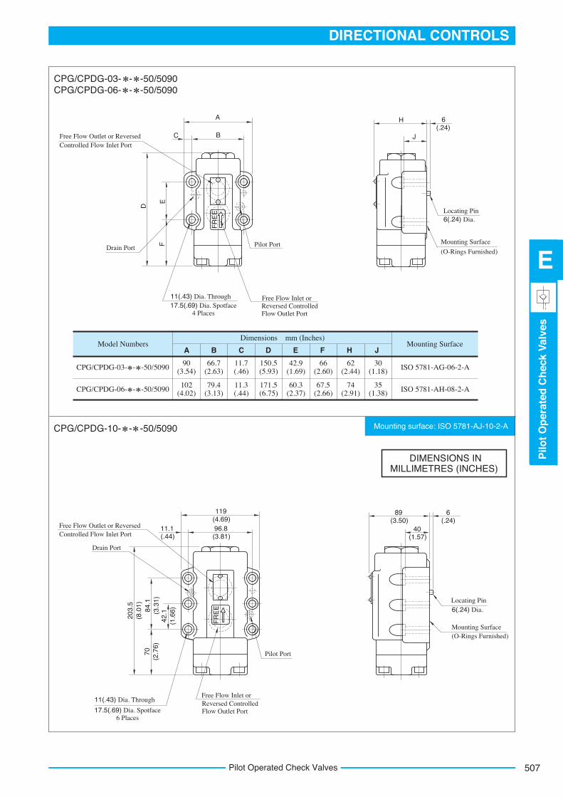
Mounting surface: ISO 5781-AJ-10-2-A
Model NumbersB
Dimensions mm (Inches)
C D E F H JAMounting Surface
CPG/CPDG-03- - -50/5090
CPG/CPDG-06- - -50/5090
ISO 5781-AG-06-2-A
ISO 5781-AH-08-2-A
90(3.54)
66.7(2.63)
11.7(.46)
150.5(5.93)
42.9(1.69)
66(2.60)
62(2.44)
30(1.18)
102(4.02)
79.4(3.13)
11.3(.44)
171.5(6.75)
60.3(2.37)
67.5(2.66)
74(2.91)
35(1.38)
FR
EE
FR
EE
A
BC
EF
D
Drain Port Pilot Port
11(.43) Dia. Through 17.5(.69) Dia. Spotface
4 Places
Free Flow Inlet or Reversed Controlled Flow Outlet Port
H
JFree Flow Outlet or Reversed Controlled Flow Inlet Port
Locating Pin 6(.24) Dia.
Mounting Surface
(O-Rings Furnished)
Locating Pin 6(.24) Dia.
Mounting Surface (O-Rings Furnished)
Drain Port
Pilot Port
11(.43) Dia. Through
17.5(.69) Dia. Spotface 6 Places
Free Flow Inlet or Reversed Controlled Flow Outlet Port
Free Flow Outlet or Reversed Controlled Flow Inlet Port
119(4.69)96.8(3.81)
11.1(.44)
42.1
(1.6
6)84.1
(3.3
1)
203.
5(8
.01)
70(2
.76)
89(3.50)
40(1.57)
6(.24)
6(.24)
CPG/CPDG-03- - -50/5090CPG/CPDG-06- - -50/5090
DIMENSIONS IN MILLIMETRES (INCHES)
CPG/CPDG-10- - -50/5090
508 Pilot Operated Check Valves
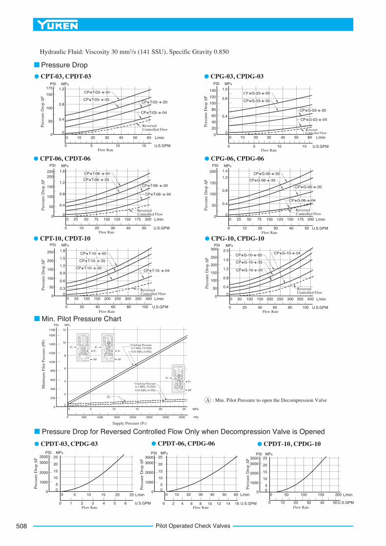
Hydraulic Fluid: Viscosity 30 mm2/s (141 SSU), Specific Gravity 0.850
Pressure Drop
CPT-03, CPDT-03 CPG-03, CPDG-03
0 2010 30 40 50 L/min0
0.8
PSI
100
175MPa
Pre
ssur
e D
rop Δ
P
50
0
0.4
1.2150
0 5 10 U.S.GPM15Flow Rate
60 0 2010 30 40 50 L/min0
0.8
PSI
100
MPa
Pre
ssur
e D
rop Δ
P
20
0
0.4
1.0
0 5 10 U.S.GPM15Flow Rate
60
40
60
80
120
140CP T-03- -50
CP T-03- -35CP T-03- -20
CP T-03- -04
CP G-03- -50
CP G-03- -35
CP G-03- -20
CP G-03- -04
ReversedControlled Flow
ReversedControlled Flow
CPT-06, CPDT-06 CPG-06, CPDG-06
CPT-10, CPDT-10 CPG-10, CPDG-10
0 5025 75 150 175 L/min0
0.8
PSI
100
200
MPa
Pre
ssur
e D
rop Δ
P
50
0
0.4
1.2150
0 10 40 U.S.GPM50Flow Rate
200100 125
20 30
1.6225
0 5025 75 150 175 L/min0
0.8
PSI
100
200
MPa
Pre
ssur
e D
rop Δ
P50
0
0.4
1.2150
0 10 40 U.S.GPM50Flow Rate
200100 125
20 30
1.4CP T-06- -50
CP T-06- -35
CP T-06- -20
CP T-06- -04
CP G-06- -50
CP G-06- -35
CP G-06- -20
CP G-06- -04
ReversedControlled Flow
ReversedControlled Flow
0 50 150 L/min0
0.9
PSI
100
200
MPa
Pre
ssur
e D
rop Δ
P
50
0
0.3
1.5
150
0 20 80 U.S.GPM100Flow Rate
200100
40 60
1.8250
250 300 350 400
0.6
1.2
0 50 150 L/min0
1.2
PSI
100
200
MPa
Pre
ssur
e D
rop Δ
P
50
0
0.4
1.6
150
0 20 80 U.S.GPM100Flow Rate
200100
40 60
2.0
250
250 300 350 400
0.8
300CP T-10- -50
CP T-10- -35
CP T-10- -20CP T-10- -04
CP G-10- -50
CP G-10- -35
CP G-10- -20
CP G-10- -04
ReversedControlled Flow
ReversedControlled Flow
Min. Pilot Pressure Chart
P2 P2
P1
PP
P1
PP
P2
P1
PP
0 MPa5 20 250
4
200
600
Min
imum
Pilo
t Pre
ssur
e (P
P)
0
6
8
800
10
2
500 PSI
Supply Pressure (P2)
150010000
PSI MPa
12
1000
1200
1400
1600
1700
400
2000 2500 3000 3500
1510
Cracking Pressure0.5 MPa (70 PSI)0.04 MPa (6 PSI)
0.5 MPa (70 PSI)Cracking Pressure
0.04 MPa (6 PSI)
A
A : Min. Pilot Pressure to open the Decompression Valve
Pressure Drop for Reversed Controlled Flow Only when Decompression Valve is Opened
CPDT-03, CPDG-03 CPDT-06, CPDG-06 CPDT-10, CPDG-10
0 10 20 L/min30 40 50 60
0 2Flow Rate
1284 6 10 14 16 U.S.GPM
0 5 10 L/min15 20 25
0 1Flow Rate
542 3 6 U.S.GPM
0
10
PSI
1000
2000
Pres
sure
Dro
p Δ
P
0
5
15
20
3500 253000
MPa
0
10
PSI
1000
2000
Pres
sure
Dro
p Δ
P
0
5
15
20
3500 25
3000
MPa
0
10
PSI
1000
2000
Pres
sure
Dro
p Δ
P
0
5
15
20
3500 25
3000
MPa
0 50 100 L/min150 200
0 10Flow Rate
504020 30 U.S.GPM
509
DIRECTIONAL CONTROLS
Pilo
tO
per
ated
Ch
eck
Val
ves
E
Pilot Operated Check Valves
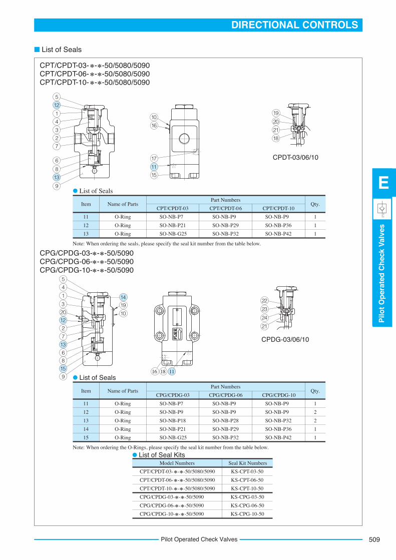
■ List of Seals
5
12
1
4
3
2
7
6
8
9
13
10
16
17
11
15
20
19
21
18
22
23
24
21
1419
111816
10
5
4
1
3
2012
2
7
13
68
15
9
Name of PartsItem Qty.CPT/CPDT-03
Part Numbers
11
12
13
O-Ring
O-Ring
O-Ring
1
1
1
CPT/CPDT-06 CPT/CPDT-10
SO-NB-P7
SO-NB-P21
SO-NB-G25
SO-NB-P9
SO-NB-P36
SO-NB-P42
SO-NB-P9
SO-NB-P29
SO-NB-P32
Name of PartsItem Qty.CPG/CPDG-03
Part Numbers
11
12
13
14
15
O-Ring
O-Ring
O-Ring
O-Ring
O-Ring
1
2
2
1
1
CPG/CPDG-06 CPG/CPDG-10
SO-NB-P7
SO-NB-P9
SO-NB-P18
SO-NB-P21
SO-NB-G25
SO-NB-P9
SO-NB-P9
SO-NB-P32
SO-NB-P36
SO-NB-P42
SO-NB-P9
SO-NB-P9
SO-NB-P28
SO-NB-P29
SO-NB-P32
Model Numbers Seal Kit Numbers
KS-CPT-03-50
KS-CPT-06-50
KS-CPT-10-50
KS-CPG-03-50
KS-CPG-06-50
KS-CPG-10-50
CPT/CPDT-03- - -50/5080/5090
CPT/CPDT-06- - -50/5080/5090
CPT/CPDT-10- - -50/5080/5090
CPG/CPDG-03- - -50/5090
CPG/CPDG-06- - -50/5090
CPG/CPDG-10- - -50/5090
CPT/CPDT-03- - -50/5080/5090CPT/CPDT-06- - -50/5080/5090CPT/CPDT-10- - -50/5080/5090
CPG/CPDG-03- - -50/5090CPG/CPDG-06- - -50/5090CPG/CPDG-10- - -50/5090
List of Seals
Note: When ordering the seals, please specify the seal kit number from the table below.
Note: When ordering the O-Rings, please specify the seal kit number from the table below.
List of Seals
List of Seal Kits
CPDG-03/06/10
CPDT-03/06/10
Related Documents