Chapter 3.8. Open Channel Systems Draft District of Columbia Stormwater Management Guidebook Page 165 Section 3.8 Open Channel Systems Definition. Vegetated open channels that are designed to capture and treat or convey the design storm volume (Stormwater Retention Volume (SWRv)). Design variants include: O-1 Grass channels O-2 Dry swales/bioswales O-3 Wet swales Open channel systems shall not be designed to provide stormwater detention except under extremely unusual conditions. Open channel systems must generally be combined with a separate facility to meet these requirements. Grass channels (O-1) can provide a modest amount of runoff filtering and volume attenuation within the stormwater conveyance system resulting in the delivery of less runoff and pollutants than a traditional system of curb and gutter, storm drain inlets, and pipes. The performance of grass channels will vary depending on the underlying soil permeability. Grass channels, however, are not capable of providing the same stormwater functions as dry swales as they lack the storage volume associated with the engineered soil media. Their runoff reduction performance can be boosted when compost amendments are added to the bottom of the swale (see Appendix K). Grass channels are a preferable alternative to both curb and gutter and storm drains as a stormwater conveyance system, where development density, topography, and soils permit. Dry swales (O-2), also known as bioswales, are essentially bioretention cells that are shallower, configured as linear channels, and covered with turf or other surface material (other than mulch and ornamental plants). The dry swale is a soil filter system that temporarily stores and then filters the desired design storm volume. Dry swales rely on a pre-mixed soil media filter below the channel that is similar to that used for bioretention. If soils are extremely permeable, runoff infiltrates into underlying soils. In most cases, however, the runoff treated by the soil media flows into an underdrain, which conveys treated runoff back to the conveyance system further downstream. The underdrain system consists of a perforated pipe within a gravel layer on the bottom of the swale, beneath the filter media. Dry swales may appear as simple grass channels with the same shape and turf cover, while others may have more elaborate landscaping. Swales can be planted with turf grass, tall meadow grasses, decorative herbaceous cover, or trees. Wet swales (O-3) can provide a modest amount of runoff filtering within the conveyance. These linear wetland cells often intercept shallow groundwater to maintain a wetland plant community. The saturated soil and wetland vegetation provide an ideal environment for gravitational settling, biological uptake, and microbial activity. On-line or off-line cells are formed within the channel to create saturated soil or shallow standing water conditions (typically less than 6 inches deep).

Welcome message from author
This document is posted to help you gain knowledge. Please leave a comment to let me know what you think about it! Share it to your friends and learn new things together.
Transcript
Chapter 3.8. Open Channel Systems
Draft District of Columbia Stormwater Management Guidebook Page 165
Section 3.8 Open Channel Systems Definition. Vegetated open channels that are designed to capture and treat or convey the design storm volume (Stormwater Retention Volume (SWRv)). Design variants include: O-1 Grass channels O-2 Dry swales/bioswales O-3 Wet swales
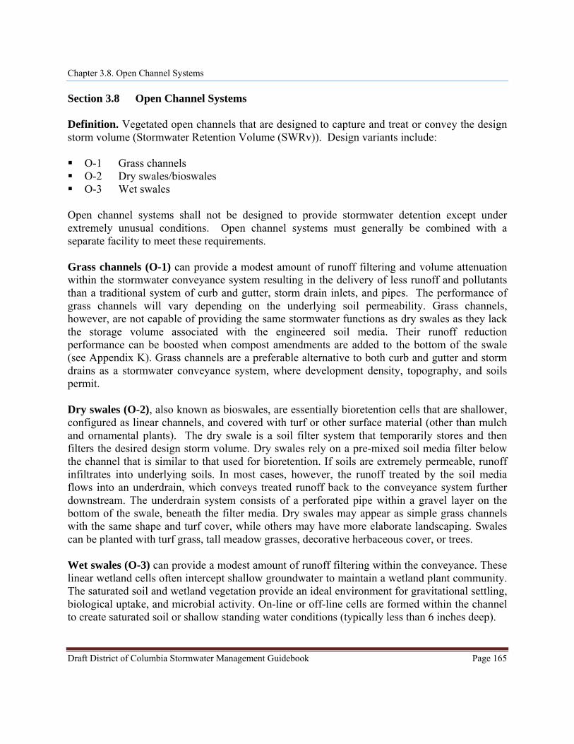
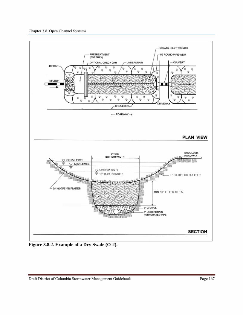
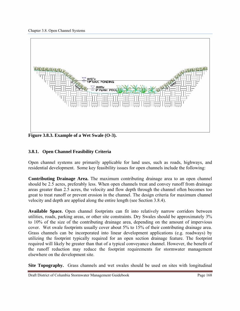
Open channel systems shall not be designed to provide stormwater detention except under extremely unusual conditions. Open channel systems must generally be combined with a separate facility to meet these requirements. Grass channels (O-1) can provide a modest amount of runoff filtering and volume attenuation within the stormwater conveyance system resulting in the delivery of less runoff and pollutants than a traditional system of curb and gutter, storm drain inlets, and pipes. The performance of grass channels will vary depending on the underlying soil permeability. Grass channels, however, are not capable of providing the same stormwater functions as dry swales as they lack the storage volume associated with the engineered soil media. Their runoff reduction performance can be boosted when compost amendments are added to the bottom of the swale (see Appendix K). Grass channels are a preferable alternative to both curb and gutter and storm drains as a stormwater conveyance system, where development density, topography, and soils permit. Dry swales (O-2), also known as bioswales, are essentially bioretention cells that are shallower, configured as linear channels, and covered with turf or other surface material (other than mulch and ornamental plants). The dry swale is a soil filter system that temporarily stores and then filters the desired design storm volume. Dry swales rely on a pre-mixed soil media filter below the channel that is similar to that used for bioretention. If soils are extremely permeable, runoff infiltrates into underlying soils. In most cases, however, the runoff treated by the soil media flows into an underdrain, which conveys treated runoff back to the conveyance system further downstream. The underdrain system consists of a perforated pipe within a gravel layer on the bottom of the swale, beneath the filter media. Dry swales may appear as simple grass channels with the same shape and turf cover, while others may have more elaborate landscaping. Swales can be planted with turf grass, tall meadow grasses, decorative herbaceous cover, or trees. Wet swales (O-3) can provide a modest amount of runoff filtering within the conveyance. These linear wetland cells often intercept shallow groundwater to maintain a wetland plant community. The saturated soil and wetland vegetation provide an ideal environment for gravitational settling, biological uptake, and microbial activity. On-line or off-line cells are formed within the channel to create saturated soil or shallow standing water conditions (typically less than 6 inches deep).
Chapter 3.8. Open Channel Systems
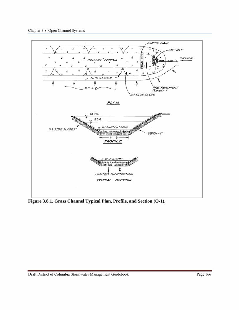
Figure 3.8.1. Grass Channel Typical Plan, Profile, and Section (O-1).
Draft District of Columbia Stormwater Management Guidebook Page 166
Chapter 3.8. Open Channel Systems
Figure 3.8.2. Example of a Dry Swale (O-2).
Draft District of Columbia Stormwater Management Guidebook Page 167
Chapter 3.8. Open Channel Systems
Draft District of Columbia Stormwater Management Guidebook Page 168
Figure 3.8.3. Example of a Wet Swale (O-3). 3.8.1. Open Channel Feasibility Criteria Open channel systems are primarily applicable for land uses, such as roads, highways, and residential development. Some key feasibility issues for open channels include the following: Contributing Drainage Area. The maximum contributing drainage area to an open channel should be 2.5 acres, preferably less. When open channels treat and convey runoff from drainage areas greater than 2.5 acres, the velocity and flow depth through the channel often becomes too great to treat runoff or prevent erosion in the channel. The design criteria for maximum channel velocity and depth are applied along the entire length (see Section 3.8.4). Available Space. Open channel footprints can fit into relatively narrow corridors between utilities, roads, parking areas, or other site constraints. Dry Swales should be approximately 3% to 10% of the size of the contributing drainage area, depending on the amount of impervious cover. Wet swale footprints usually cover about 5% to 15% of their contributing drainage area. Grass channels can be incorporated into linear development applications (e.g. roadways) by utilizing the footprint typically required for an open section drainage feature. The footprint required will likely be greater than that of a typical conveyance channel. However, the benefit of the runoff reduction may reduce the footprint requirements for stormwater management elsewhere on the development site. Site Topography. Grass channels and wet swales should be used on sites with longitudinal
Chapter 3.8. Open Channel Systems
Draft District of Columbia Stormwater Management Guidebook Page 169
slopes of less than 4%. Check dams can be used to reduce the effective slope of the channel and lengthen the contact time to enhance filtering and/or infiltration. Longitudinal slopes of less than 2% are ideal and may eliminate the need for check dams. However, channels designed with longitudinal slopes of less than 1% should be monitored carefully during construction to ensure a continuous grade, in order to avoid flat areas with pockets of standing water. For dry swales, check dams will be necessary regardless of the longitudinal slope to create the necessary ponding volume. Land Uses. Open channels can be used in residential, commercial, or institutional development settings. When open channels are used for both conveyance and water quality treatment, they should be applied only in linear configurations parallel to the contributing impervious cover, such as roads and small parking areas. The linear nature of open channels makes them well-suited to treat highway or low- and medium-density residential road runoff, if there is adequate right-of-way width and distance between driveways. Typical applications of open channels include the following, as long as drainage area limitations and design criteria can be met: Within a roadway right-of-way; Along the margins of small parking lots; Oriented from the roof (downspout discharge) to the street; Disconnecting small impervious areas; and Used to treat the managed turf areas of sports fields, golf courses, and other turf-intensive
land uses, or to treat drainage areas with both impervious and managed turf cover (such as residential streets and yards).
Open channels are not recommended when residential density exceeds more than 4 dwelling units per acre, due to a lack of available land and the frequency of driveway crossings along the channel. Open channels can also provide pre-treatment for other stormwater treatment practices. Available Hydraulic Head. A minimum amount of hydraulic head is needed to implement open channels in order to ensure positive drainage and conveyance through the channel. The hydraulic head for wet swales and grass channels is measured as the elevation difference between the channel inflow and outflow point. The hydraulic head for dry swales is measured as the elevation difference between the inflow point and the storm drain invert. Dry swales typically require 3 to 5 feet of hydraulic head since they have both a filter bed and underdrain. Hydraulic Capacity. Open channels are typically designed as on-line practices which must be designed with enough capacity to (1) convey runoff from the 2-year and 15-year design storms at
Chapter 3.8. Open Channel Systems
Draft District of Columbia Stormwater Management Guidebook Page 170
non-erosive velocities, and (2) contain the 15-year flow within the banks of the swale. This means that the swale’s surface dimensions are more often determined by the need to pass the 15-year storm events, which can be a constraint in the siting of open channels within existing rights-of-way (e.g. constrained by sidewalks). Depth to Water Table. Designers should ensure that the bottom of dry swales and grass channels is at least 2 feet above the seasonally high groundwater table, to ensure that groundwater does not intersect the filter bed, since this could lead to groundwater contamination or practice failure. It is permissible for wet swales to intersect the water table. Soils. Soil conditions do not constrain the use of open channels, although they do dictate some design considerations: Dry swales in soils with infiltration rates of less than 1/2 inch per hour may need an
underdrain. Designers must verify site-specific soil permeability at the proposed location using the methods for on-site soil investigation presented in Appendix P, in order to eliminate the requirements for a dry swale underdrain. A soil test should be conducted for every 1,000 square feet of dry swale.
Grass channels situated on low-permeability soils may incorporate compost amendments in order to improve performance (see Appendix K).
Wet swales work best on the more impermeable Hydrologic Soil Group (HSG) C or D soils. Infill soil locations, geotechnical investigations are required to determine if the use of an
impermeable liner and underdrain are necessary for open channel designs. Utilities. Typically, utilities can cross linear channels if they are specially protected (e.g. double-casing). Interference with underground utilities should be avoided, if possible. When large site development is undertaken, the expectation of achieving avoidance will be high. Conflicts may be commonplace on smaller sites and in the public right of way. Where conflicts cannot be avoided, these guidelines shall be followed, Consult with each utility company on recommended offsets that will allow utility
maintenance work with minimal disturbance to the BMP. Whenever possible, coordinate with utility companies to allow them to replace or relocate
their aging infrastructure while BMPs are being implemented. BMP and utility conflicts will be a common occurrence in public right of way projects.
However, the standard solution to utility conflict should be the acceptance of conflict provided sufficient soil coverage over the utility can be assured.
Additionally, when accepting utility conflict into the BMP design, it is understood that the BMP will be temporarily impacted during utility maintenance but restored to its original condition.
Avoidance of Irrigation or Baseflow. Open channels should be located so as to avoid inputs of
Chapter 3.8. Open Channel Systems
Draft District of Columbia Stormwater Management Guidebook Page 171
springs, irrigation systems, chlorinated wash-water, or other dry weather flows. Setbacks. Open channels are typically set back at least 10 feet down-gradient from building foundations or as approved by a professional geotechnical engineer. Hotspot Land Use. Runoff from hotspot land uses should not be treated with infiltrating dry swales due to the potential interaction with the water table and the risk that hydrocarbons, trace metals, and other toxic pollutants could migrate into the groundwater. An impermeable liner should be used for filtration of hotspot runoff for dry swales. Grass channels can typically be used to convey runoff from stormwater hotspots, but they do not qualify as a hotspot treatment mechanism. Wet swales are not recommended to treat stormwater hotspots, due to the potential interaction with the water table and the risk that hydrocarbons, trace metals, and other toxic pollutants could migrate into the groundwater. For a list of designated stormwater hotspot operations, consult Appendix Q. On sites with existing contaminated soils, as indicated in Appendix Q, infiltration is not allowed. Dry and wet swales must include an impermeable liner. 3.8.2. Open Channel Conveyance Criteria The bottom width and slope of a grass channel should be designed such that the velocity of flow from the design storm provides a minimum hydraulic residence time (average travel time for a particle of water through a water body) of 9 minutes for the peak flows from the SWRv or design storm. Check dams may be used to achieve the needed runoff reduction volume, as well as to reduce the flow velocity. Check dams should be spaced based on channel slope and ponding requirements, consistent with the criteria in Section 3.8.4 Open Channel Design Criteria. Open channels should also convey the 2- and 15-year storms at non-erosive velocities (generally less than 6 fps) for the soil and vegetative cover provided. The final designed channel shall provide 1 foot minimum freeboard above the designated water surface profile of the channel. The analysis should evaluate the flow profile through the channel at normal depth, as well as the flow depth over top of the check dams. 3.8.3. Open Channel Pretreatment Criteria Pretreatment is required for open channels to dissipate energy, trap sediments, and slow down the runoff velocity. The selection of a pre-treatment method depends on whether the channel will experience sheet flow or concentrated flow. Several options are as follows:
Chapter 3.8. Open Channel Systems
Draft District of Columbia Stormwater Management Guidebook Page 172
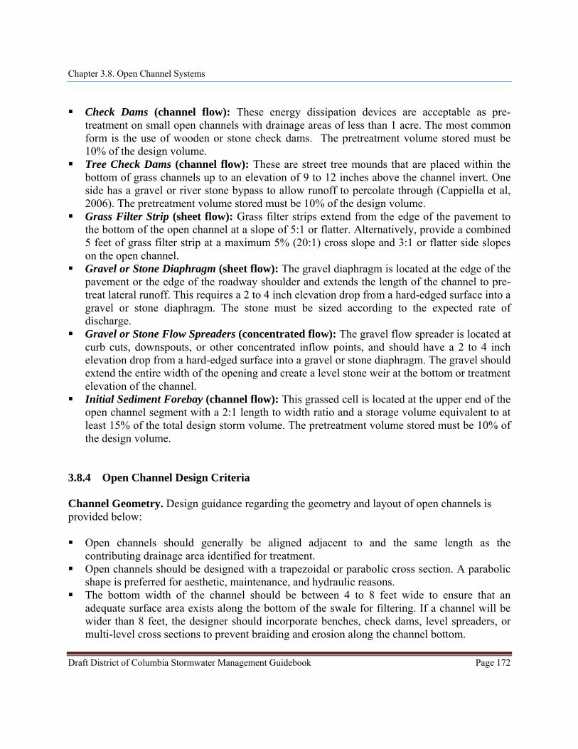
Check Dams (channel flow): These energy dissipation devices are acceptable as pre-
treatment on small open channels with drainage areas of less than 1 acre. The most common form is the use of wooden or stone check dams. The pretreatment volume stored must be 10% of the design volume.
Tree Check Dams (channel flow): These are street tree mounds that are placed within the bottom of grass channels up to an elevation of 9 to 12 inches above the channel invert. One side has a gravel or river stone bypass to allow runoff to percolate through (Cappiella et al, 2006). The pretreatment volume stored must be 10% of the design volume.
Grass Filter Strip (sheet flow): Grass filter strips extend from the edge of the pavement to the bottom of the open channel at a slope of 5:1 or flatter. Alternatively, provide a combined 5 feet of grass filter strip at a maximum 5% (20:1) cross slope and 3:1 or flatter side slopes on the open channel.
Gravel or Stone Diaphragm (sheet flow): The gravel diaphragm is located at the edge of the pavement or the edge of the roadway shoulder and extends the length of the channel to pre-treat lateral runoff. This requires a 2 to 4 inch elevation drop from a hard-edged surface into a gravel or stone diaphragm. The stone must be sized according to the expected rate of discharge.
Gravel or Stone Flow Spreaders (concentrated flow): The gravel flow spreader is located at curb cuts, downspouts, or other concentrated inflow points, and should have a 2 to 4 inch elevation drop from a hard-edged surface into a gravel or stone diaphragm. The gravel should extend the entire width of the opening and create a level stone weir at the bottom or treatment elevation of the channel.
Initial Sediment Forebay (channel flow): This grassed cell is located at the upper end of the open channel segment with a 2:1 length to width ratio and a storage volume equivalent to at least 15% of the total design storm volume. The pretreatment volume stored must be 10% of the design volume.
3.8.4 Open Channel Design Criteria Channel Geometry. Design guidance regarding the geometry and layout of open channels is provided below: Open channels should generally be aligned adjacent to and the same length as the
contributing drainage area identified for treatment. Open channels should be designed with a trapezoidal or parabolic cross section. A parabolic
shape is preferred for aesthetic, maintenance, and hydraulic reasons. The bottom width of the channel should be between 4 to 8 feet wide to ensure that an
adequate surface area exists along the bottom of the swale for filtering. If a channel will be wider than 8 feet, the designer should incorporate benches, check dams, level spreaders, or multi-level cross sections to prevent braiding and erosion along the channel bottom.
Chapter 3.8. Open Channel Systems
Draft District of Columbia Stormwater Management Guidebook Page 173
Open channel side slopes should be no steeper than 3H:1V for ease of mowing and routine maintenance. Flatter slopes are encouraged, where adequate space is available, to enhance pre-treatment of sheet flows entering the channel.
Check dams. Check dams may be used for pre-treatment, to break up slopes, and to increase the hydraulic residence time in the channel. Design requirements for check dams are as follows: Check dams should be spaced based on the channel slope, as needed to increase residence
time, provide design storm storage volume, or any additional volume attenuation requirements. In typical spacing, the ponded water at a downhill check dam should not touch the toe of the upstream check dam. More frequent spacing may be desirable in dry swales to increase the ponding volume.
The maximum desired check dam height is 12 inches, for maintenance purposes. However, for some sites, a maximum of 18 inches can be allowed, with additional design elements to ensure the stability of the check dam and the adjacent and underlying soils. The average ponding depth throughout the channel should be 12 inches.
Armoring may be needed at the downstream toe of the check dam to prevent erosion. Check dams must be firmly anchored into the side-slopes to prevent outflanking; check dams
must also be anchored into the channel bottom so as to prevent hydrostatic head from pushing out the underlying soils.
Check dams must be designed with a center weir sized to pass the channel design storm peak flow (15-year storm event for man-made channels).
For grass channels, each check dam should have a weep hole or similar drainage feature so it can dewater after storms. This is not appropriate for dry swales.
Check dams should be composed of wood, concrete, stone, compacted soil, or other non-erodible material, or should be configured with elevated driveway culverts.
Individual channel segments formed by check dams or driveways should generally be at least 25 to 40 feet in length.
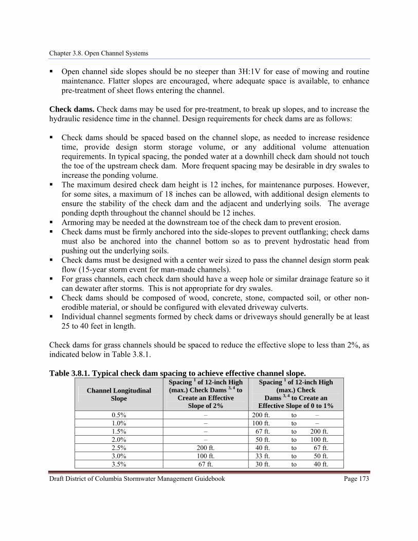
Check dams for grass channels should be spaced to reduce the effective slope to less than 2%, as indicated below in Table 3.8.1.
Table 3.8.1. Typical check dam spacing to achieve effective channel slope.
Channel Longitudinal Slope
Spacing 1 of 12-inch High (max.) Check Dams 3, 4 to
Create an Effective Slope of 2%
Spacing 1 of 12-inch High (max.) Check
Dams 3, 4 to Create an Effective Slope of 0 to 1%
0.5% – 200 ft. to – 1.0% – 100 ft. to – 1.5% – 67 ft. to 200 ft. 2.0% – 50 ft. to 100 ft. 2.5% 200 ft. 40 ft. to 67 ft. 3.0% 100 ft. 33 ft. to 50 ft. 3.5% 67 ft. 30 ft. to 40 ft.
Chapter 3.8. Open Channel Systems
Draft District of Columbia Stormwater Management Guidebook Page 174
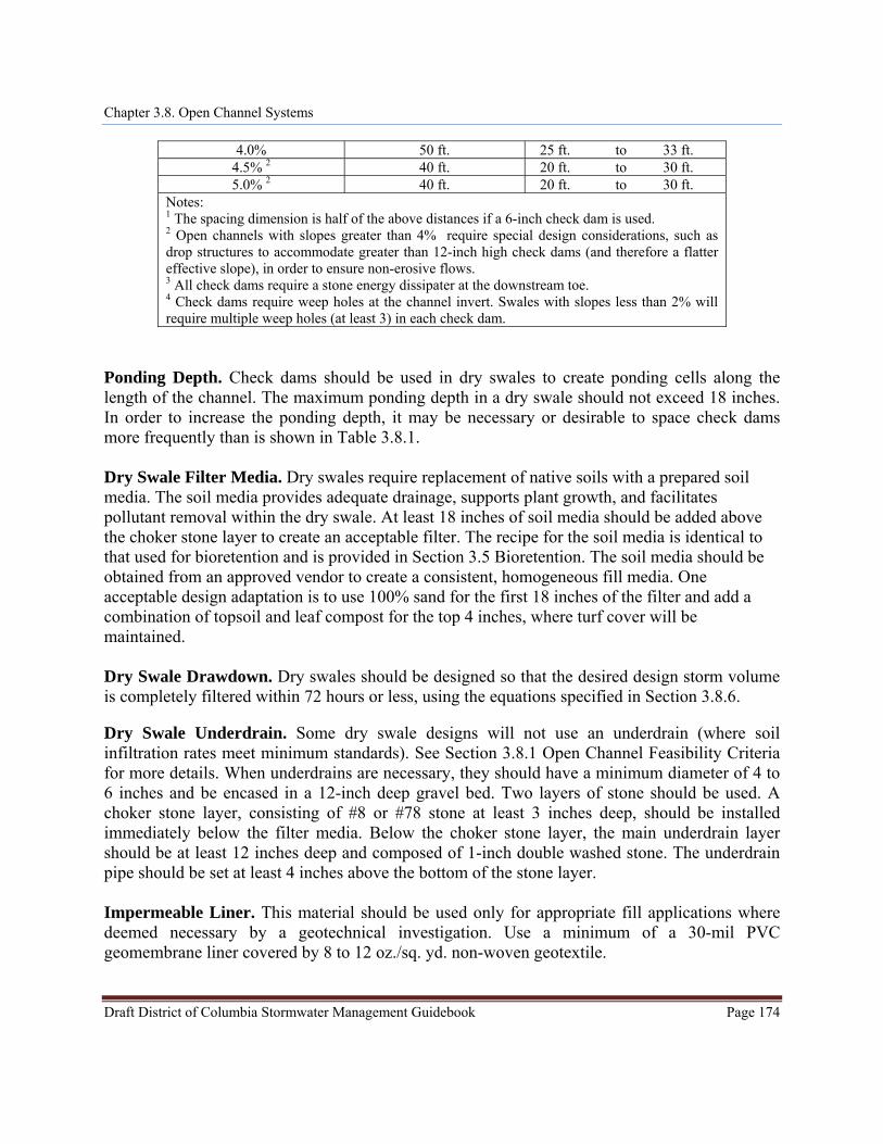
4.0% 50 ft. 25 ft. to 33 ft. 4.5% 2 40 ft. 20 ft. to 30 ft. 5.0% 2 40 ft. 20 ft. to 30 ft.
Notes: 1 The spacing dimension is half of the above distances if a 6-inch check dam is used. 2 Open channels with slopes greater than 4% require special design considerations, such as drop structures to accommodate greater than 12-inch high check dams (and therefore a flatter effective slope), in order to ensure non-erosive flows. 3 All check dams require a stone energy dissipater at the downstream toe. 4 Check dams require weep holes at the channel invert. Swales with slopes less than 2% will require multiple weep holes (at least 3) in each check dam.
Ponding Depth. Check dams should be used in dry swales to create ponding cells along the length of the channel. The maximum ponding depth in a dry swale should not exceed 18 inches. In order to increase the ponding depth, it may be necessary or desirable to space check dams more frequently than is shown in Table 3.8.1. Dry Swale Filter Media. Dry swales require replacement of native soils with a prepared soil media. The soil media provides adequate drainage, supports plant growth, and facilitates pollutant removal within the dry swale. At least 18 inches of soil media should be added above the choker stone layer to create an acceptable filter. The recipe for the soil media is identical to that used for bioretention and is provided in Section 3.5 Bioretention. The soil media should be obtained from an approved vendor to create a consistent, homogeneous fill media. One acceptable design adaptation is to use 100% sand for the first 18 inches of the filter and add a combination of topsoil and leaf compost for the top 4 inches, where turf cover will be maintained. Dry Swale Drawdown. Dry swales should be designed so that the desired design storm volume is completely filtered within 72 hours or less, using the equations specified in Section 3.8.6. Dry Swale Underdrain. Some dry swale designs will not use an underdrain (where soil infiltration rates meet minimum standards). See Section 3.8.1 Open Channel Feasibility Criteria for more details. When underdrains are necessary, they should have a minimum diameter of 4 to 6 inches and be encased in a 12-inch deep gravel bed. Two layers of stone should be used. A choker stone layer, consisting of #8 or #78 stone at least 3 inches deep, should be installed immediately below the filter media. Below the choker stone layer, the main underdrain layer should be at least 12 inches deep and composed of 1-inch double washed stone. The underdrain pipe should be set at least 4 inches above the bottom of the stone layer. Impermeable Liner. This material should be used only for appropriate fill applications where deemed necessary by a geotechnical investigation. Use a minimum of a 30-mil PVC geomembrane liner covered by 8 to 12 oz./sq. yd. non-woven geotextile.
Chapter 3.8. Open Channel Systems
Draft District of Columbia Stormwater Management Guidebook Page 175
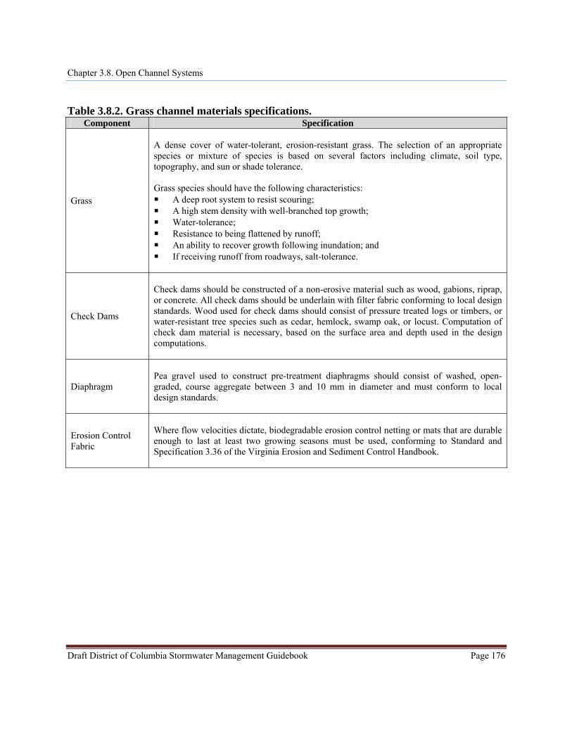
Dry Swale Observation Well. If the contributing drainage area exceeds 1 acre, a dry swale should include observation wells with cleanout pipes along the length of the swale. The wells should be tied into any Ts or Ys in the underdrain system and should extend upwards to be flush with surface, with a vented cap. Grass Channel Material Specifications. The basic material specifications for grass channels are outlined in Table 3.8.2 below.
Chapter 3.8. Open Channel Systems
Draft District of Columbia Stormwater Management Guidebook Page 176
Table 3.8.2. Grass channel materials specifications.
Component Specification
Grass
A dense cover of water-tolerant, erosion-resistant grass. The selection of an appropriate species or mixture of species is based on several factors including climate, soil type, topography, and sun or shade tolerance. Grass species should have the following characteristics: A deep root system to resist scouring; A high stem density with well-branched top growth; Water-tolerance; Resistance to being flattened by runoff; An ability to recover growth following inundation; and If receiving runoff from roadways, salt-tolerance.
Check Dams
Check dams should be constructed of a non-erosive material such as wood, gabions, riprap, or concrete. All check dams should be underlain with filter fabric conforming to local design standards. Wood used for check dams should consist of pressure treated logs or timbers, or water-resistant tree species such as cedar, hemlock, swamp oak, or locust. Computation of check dam material is necessary, based on the surface area and depth used in the design computations.
Diaphragm
Pea gravel used to construct pre-treatment diaphragms should consist of washed, open-graded, course aggregate between 3 and 10 mm in diameter and must conform to local design standards.
Erosion Control Fabric
Where flow velocities dictate, biodegradable erosion control netting or mats that are durable enough to last at least two growing seasons must be used, conforming to Standard and Specification 3.36 of the Virginia Erosion and Sediment Control Handbook.
Chapter 3.8. Open Channel Systems
Draft District of Columbia Stormwater Management Guidebook Page 177
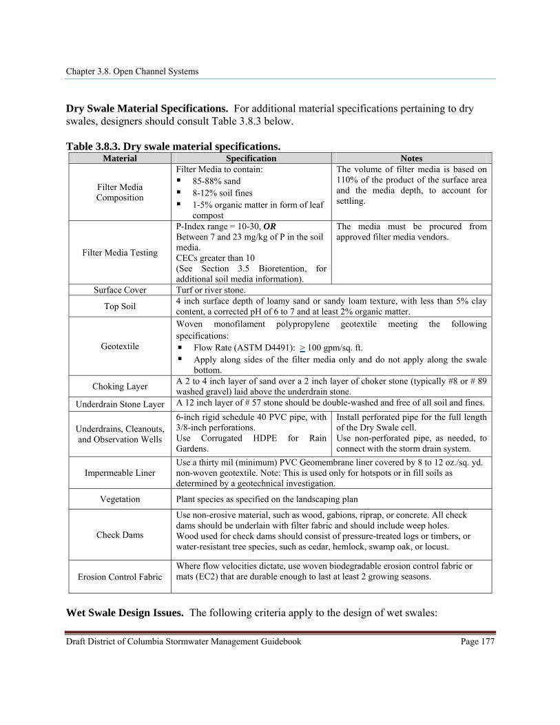
Dry Swale Material Specifications. For additional material specifications pertaining to dry swales, designers should consult Table 3.8.3 below. Table 3.8.3. Dry swale material specifications.
Material Specification Notes
Filter Media Composition
Filter Media to contain: 85-88% sand 8-12% soil fines 1-5% organic matter in form of leaf
compost
The volume of filter media is based on 110% of the product of the surface area and the media depth, to account for settling.
Filter Media Testing
P-Index range = 10-30, OR Between 7 and 23 mg/kg of P in the soil media. CECs greater than 10 (See Section 3.5 Bioretention, for additional soil media information).
The media must be procured from approved filter media vendors.
Surface Cover Turf or river stone.
Top Soil 4 inch surface depth of loamy sand or sandy loam texture, with less than 5% clay content, a corrected pH of 6 to 7 and at least 2% organic matter.
Geotextile
Woven monofilament polypropylene geotextile meeting the following specifications:
Flow Rate (ASTM D4491): > 100 gpm/sq. ft. Apply along sides of the filter media only and do not apply along the swale
bottom.
Choking Layer A 2 to 4 inch layer of sand over a 2 inch layer of choker stone (typically #8 or # 89 washed gravel) laid above the underdrain stone.
Underdrain Stone Layer A 12 inch layer of # 57 stone should be double-washed and free of all soil and fines.
Underdrains, Cleanouts, and Observation Wells
6-inch rigid schedule 40 PVC pipe, with 3/8-inch perforations. Use Corrugated HDPE for Rain Gardens.
Install perforated pipe for the full length of the Dry Swale cell. Use non-perforated pipe, as needed, to connect with the storm drain system.
Impermeable Liner Use a thirty mil (minimum) PVC Geomembrane liner covered by 8 to 12 oz./sq. yd. non-woven geotextile. Note: This is used only for hotspots or in fill soils as determined by a geotechnical investigation.
Vegetation Plant species as specified on the landscaping plan
Check Dams
Use non-erosive material, such as wood, gabions, riprap, or concrete. All check dams should be underlain with filter fabric and should include weep holes. Wood used for check dams should consist of pressure-treated logs or timbers, or water-resistant tree species, such as cedar, hemlock, swamp oak, or locust.
Erosion Control Fabric Where flow velocities dictate, use woven biodegradable erosion control fabric or mats (EC2) that are durable enough to last at least 2 growing seasons.
Wet Swale Design Issues. The following criteria apply to the design of wet swales:
Chapter 3.8. Open Channel Systems
Draft District of Columbia Stormwater Management Guidebook Page 178
The average normal pool depth (dry weather) throughout the swale should be 6 inches or
less. The maximum temporary ponding depth in any single Wet Swale cell should not exceed 18
inches at the most downstream point (e.g. at a check dam or driveway culvert). Check dams should be spaced as needed to maintain the effective longitudinal slope. Individual Wet Swale segments formed by check dams or driveways should generally be at
least 25 to 40 feet in length. Wet Swale side slopes should be no steeper than 4H:1V to enable wetland plant growth.
Flatter slopes are encouraged where adequate space is available, to enhance pre-treatment of sheet flows entering the channel. Under no circumstances are side slopes to steeper than 3H:1V.
Grass Channel Enhancement using Compost Soil Amendments. Soil compost amendments serve to increase the runoff reduction capability of a grass channel. The following design criteria apply when compost amendments are used: The compost-amended strip should extend over the length and width of the channel bottom,
and the compost should be incorporated to a depth as outlined in Appendix K. The amended area will need to be rapidly stabilized with perennial, salt tolerant grass
species. For grass channels on steep slopes, it may be necessary to install a protective biodegradable
geotextile fabric to protect the compost-amended soils. Care must be taken to consider the erosive characteristics of the amended soils when selecting an appropriate geotextile.
Grass Channel Sizing. Unlike other BMPs, grass channels are designed based on a peak rate of flow. Designers must demonstrate channel conveyance and treatment capacity in accordance with the following guidelines: Hydraulic capacity should be verified using Manning’s Equation or an accepted equivalent
method, such as erodibility factors and vegetal retardance. The flow depth for the peak flow generated by the SWRv should be maintained at 4 inches or
less. Manning’s “n” value for grass channels should be 0.2 for flow depths up to 4 inches,
decreasing to 0.03 at a depth of 12 inches and above, which would apply to the 2-year and 15-year storms if an on-line application (Haan et. al, 1994).
Peak flow rates for the 2-year and 15-year frequency storms must be non-erosive, in accordance with Table 3.8.4 below (see Section 3.8.5 Open Channel Landscaping Criteria), or subject to a site-specific analysis of the channel lining material and vegetation; and the 15-year peak flow rate must be contained within the channel banks (with a minimum of 6 inches of freeboard).
Chapter 3.8. Open Channel Systems
Calculations for peak flow depth and velocity should reflect any increase in flow along the length of the channel, as appropriate. If a single flow is used, the flow at the outlet should be used.
The hydraulic residence time (e.g. the average travel time for a particle of water through a water body) should be a minimum of 9 minutes for the peak flows from the SWRv or design storm (Mar et al., 1982; Barrett et al., 1998; Washington State Department of Ecology, 2005). If flow enters the swale at several locations, a 9 minute minimum hydraulic residence time should be demonstrated for each entry point, using Equations 3.8.1 – 3.8.5 below.
The bottom width of the grass channel is therefore sized to maintain the appropriate flow geometry as follows:
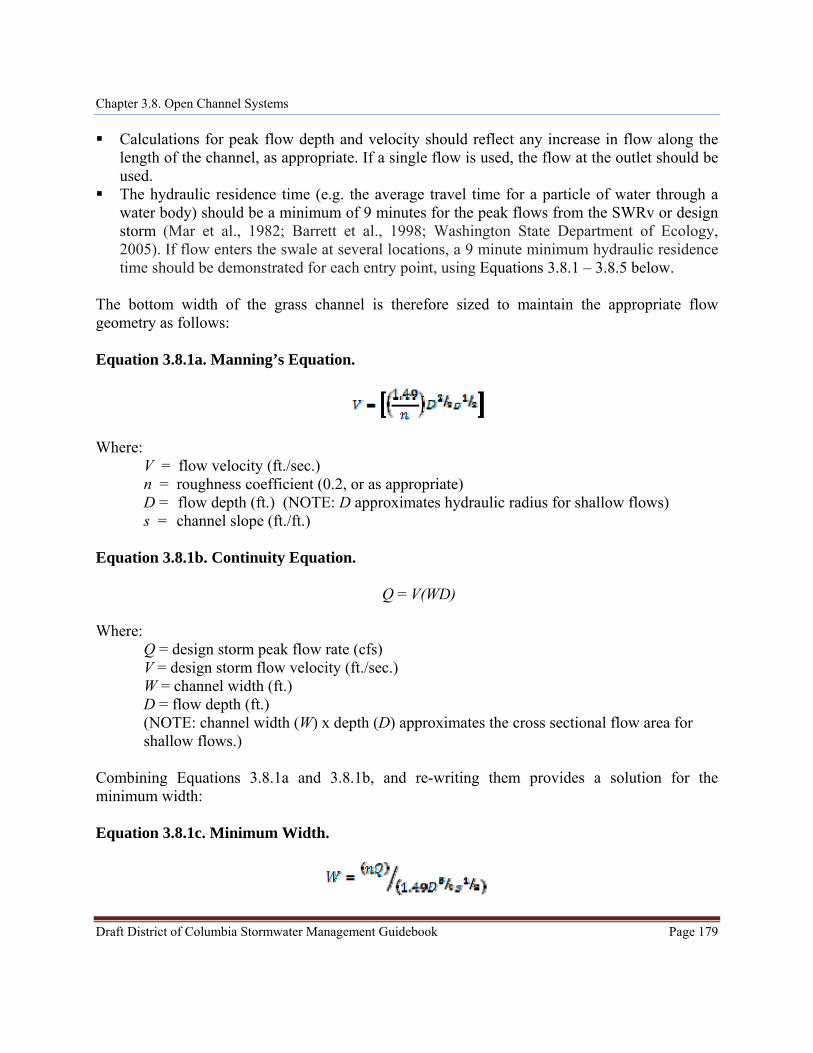
Equation 3.8.1a. Manning’s Equation.
Where:
V = flow velocity (ft./sec.) n = roughness coefficient (0.2, or as appropriate) D = flow depth (ft.) (NOTE: D approximates hydraulic radius for shallow flows) s = channel slope (ft./ft.)
Equation 3.8.1b. Continuity Equation.
Q = V(WD)
Where: Q = design storm peak flow rate (cfs) V = design storm flow velocity (ft./sec.) W = channel width (ft.) D = flow depth (ft.) (NOTE: channel width (W) x depth (D) approximates the cross sectional flow area for shallow flows.)
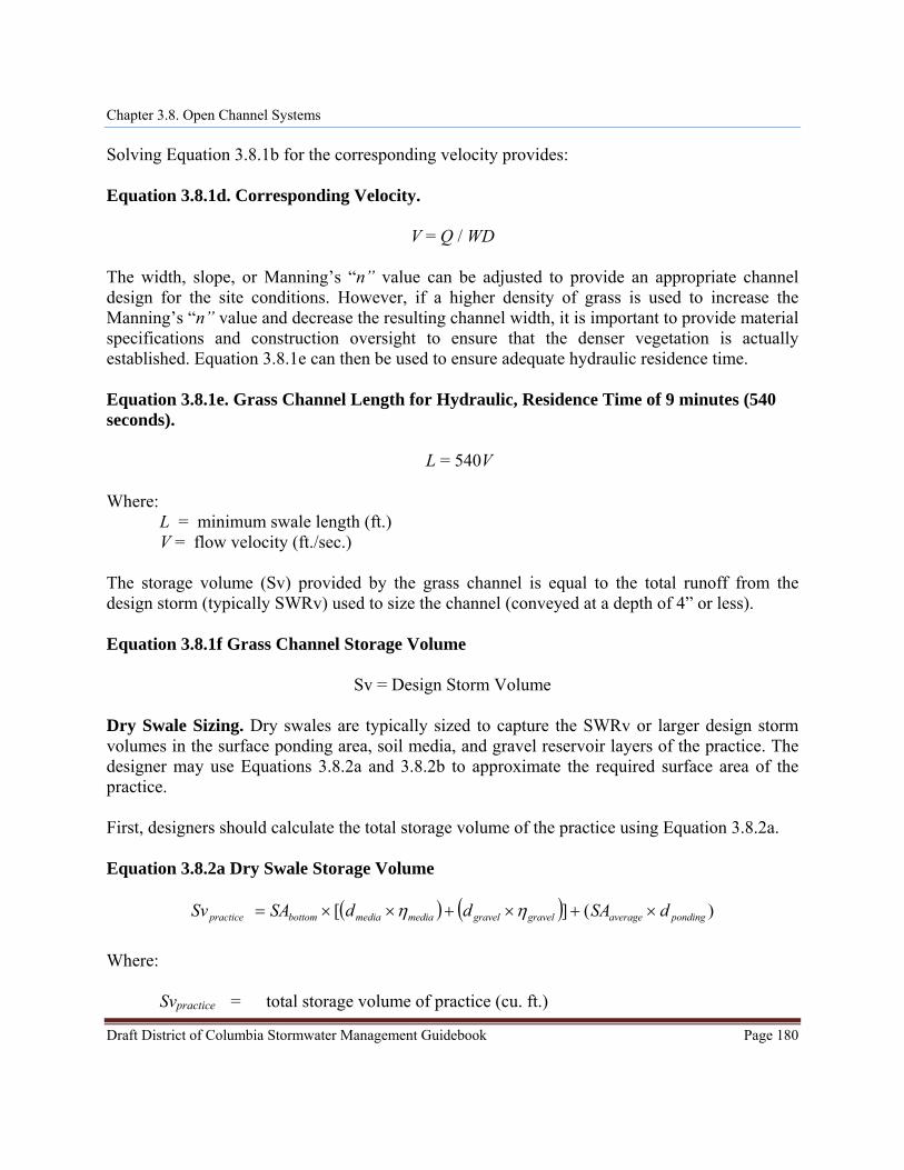
Combining Equations 3.8.1a and 3.8.1b, and re-writing them provides a solution for the minimum width:
Equation 3.8.1c. Minimum Width.
Draft District of Columbia Stormwater Management Guidebook Page 179
Chapter 3.8. Open Channel Systems
Solving Equation 3.8.1b for the corresponding velocity provides:
Equation 3.8.1d. Corresponding Velocity.
V = Q / WD The width, slope, or Manning’s “n” value can be adjusted to provide an appropriate channel design for the site conditions. However, if a higher density of grass is used to increase the Manning’s “n” value and decrease the resulting channel width, it is important to provide material specifications and construction oversight to ensure that the denser vegetation is actually established. Equation 3.8.1e can then be used to ensure adequate hydraulic residence time. Equation 3.8.1e. Grass Channel Length for Hydraulic, Residence Time of 9 minutes (540 seconds).
L = 540V Where:
L = minimum swale length (ft.) V = flow velocity (ft./sec.)
The storage volume (Sv) provided by the grass channel is equal to the total runoff from the design storm (typically SWRv) used to size the channel (conveyed at a depth of 4” or less).
Equation 3.8.1f Grass Channel Storage Volume
Sv = Design Storm Volume
Dry Swale Sizing. Dry swales are typically sized to capture the SWRv or larger design storm volumes in the surface ponding area, soil media, and gravel reservoir layers of the practice. The designer may use Equations 3.8.2a and 3.8.2b to approximate the required surface area of the practice. First, designers should calculate the total storage volume of the practice using Equation 3.8.2a.
Equation 3.8.2a Dry Swale Storage Volume
( ) ( ) )(][ pondingaveragegravelgravelmediamediabottompractice dSAddSASv ×+×+××= ηη
Where:
Svpractice = total storage volume of practice (cu. ft.)
Draft District of Columbia Stormwater Management Guidebook Page 180
Chapter 3.8. Open Channel Systems
Draft District of Columbia Stormwater Management Guidebook Page 181
SAbottom = bottom surface area of practice (sq. ft.) dmedia = depth of the filter media (ft) ηmedia = effective porosity of the filter media (typically 0.25) dgravel = depth of the underdrain and underground storage gravel layer(ft) ηgravel = effective porosity of the gravel layer (typically 0.4) SAaverage = the average surface area of the practice (sq. ft.) typically = ½ x (top area
plus the bottom (SAbottom) area) dponding = the maximum ponding depth of the practice (ft).
Equation 3.8.2a can be modified if the storage depths of the soil media, gravel layer, or ponded water vary in the actual design or with the addition of any surface or subsurface storage components (e.g., additional area of surface ponding, subsurface storage chambers, etc.). The maximum depth of ponding in the dry swale should not exceed 18 inches. If storage practices will be provided off-line or in series with the dry swale, the storage practices should be sized using the guidance in Section 3.11 Storage. During high intensity storm events, the dry swale will fill up faster than the collected stormwater is able to filter through the soil media. To ensure that the runoff volume from these storms is filtered, the surface storage volume of the system (including pretreatment) shall be designed to store at least 75% of the SWRv or alternative design storm prior to filtration. The surface storage volume (Vponding) of the practice, expressed as (SAaverage x dponding) in Eq. 3.8.2a, should be sized to ensure that at least 75% of the SWRv or alternative design storm volume is captured. If Vponding is less than 75% of the design storm volume, the total storage volume of the practice counted toward compliance (Sv) is reduced to the ponding volume divided by 0.75, as determined using Equation 3.8.2b. If Vponding is greater than or equal to 75% of the design storm volume, then the total storage volume of the practice (Svpractice) is counted towards compliance such that Sv equals Svpractice , Equation 3.8.2c.
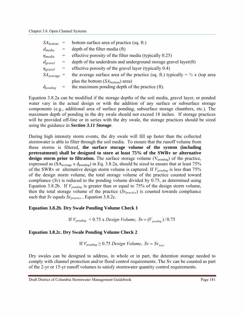
Equation 3.8.2b. Dry Swale Ponding Volume Check 1
75.0/)( pondingVSv
= If Vponding < 0.75 x Design Volume,
Equation 3.8.2c. Dry Swale Ponding Volume Check 2
If Vponding ≥ 0.75 Design Volume, totalSvSv = Dry swales can be designed to address, in whole or in part, the detention storage needed to comply with channel protection and/or flood control requirements. The Sv can be counted as part of the 2-yr or 15-yr runoff volumes to satisfy stormwater quantity control requirements.
Chapter 3.8. Open Channel Systems
Draft District of Columbia Stormwater Management Guidebook Page 182
Note: In order to increase the storage volume of a dry swale, the ponding surface area may be increased beyond the filter media surface area. However, the top surface are of the practice (at the top of the ponding elevation) may not be more than twice the size of surface area of the filter media (SAbottom). Wet Swale Sizing. Wet swales can be designed to capture and treat the SWRv remaining from any upstream stormwater retention practices. The storage volume is made up of the temporary and permanent storage created within each wet swale cell. This includes the permanent pool volume and up to 12 inches of temporary storage created by check dams or other design features that has 24 hours extended detention. The storage volume (Sv) of the practice is equal to the volume provided by the pond permanent pool plus the 24-hour extended detention volume provided by the practice (Equation 3.9.3). The total Sv cannot exceed the design SWRv. Equation 3.8.3. Wet Swale Storage Volume
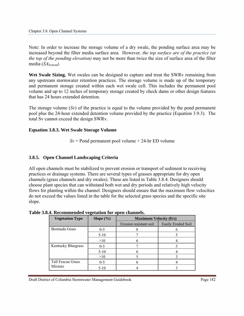
Sv = Pond permanent pool volume + 24-hr ED volume 3.8.5. Open Channel Landscaping Criteria All open channels must be stabilized to prevent erosion or transport of sediment to receiving practices or drainage systems. There are several types of grasses appropriate for dry open channels (grass channels and dry swales). These are listed in Table 3.8.4. Designers should choose plant species that can withstand both wet and dry periods and relatively high velocity flows for planting within the channel. Designers should ensure that the maximum flow velocities do not exceed the values listed in the table for the selected grass species and the specific site slope. Table 3.8.4. Recommended vegetation for open channels.
Vegetation Type Slope (%) Maximum Velocity (ft/s) Erosion resistant soil Easily Eroded Soil
0-5 8 6 5-10 7 5
Bermuda Grass
>10 6 4 0-5 7 5
5-10 6 4 Kentucky Bluegrass
>10 5 3 0-5 6 4 Tall Fescue Grass
Mixture 5-10 4 3
Chapter 3.8. Open Channel Systems
Draft District of Columbia Stormwater Management Guidebook Page 183
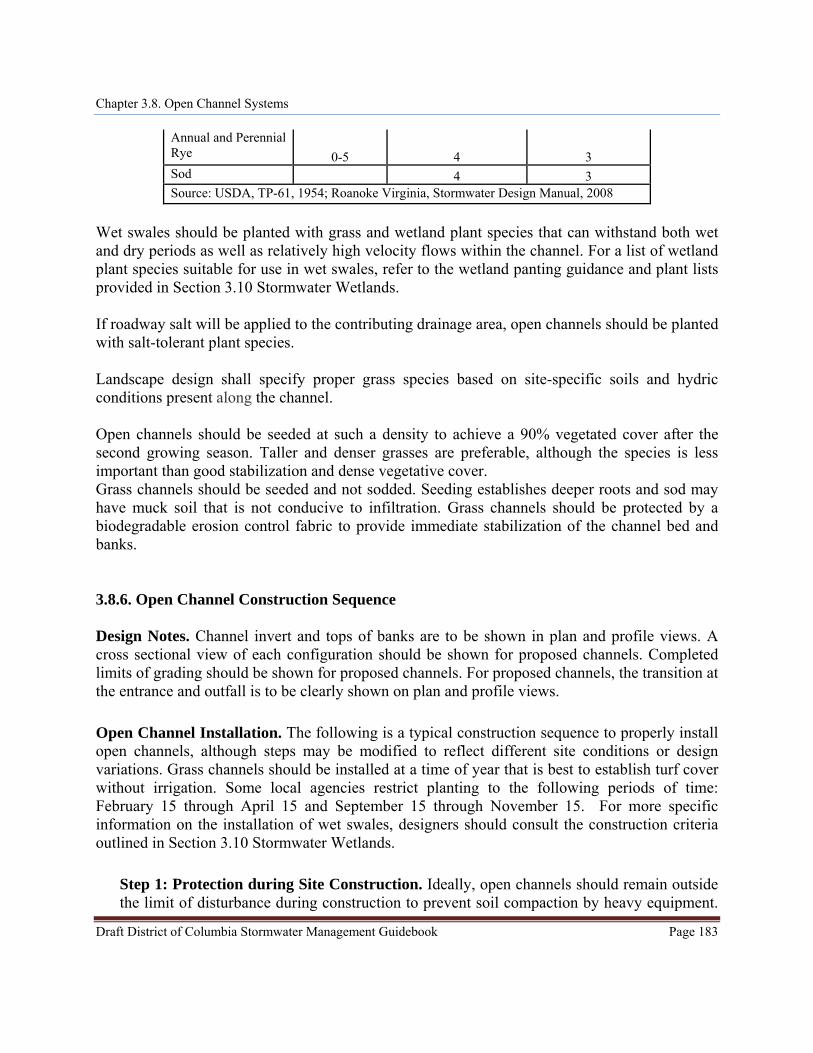
Annual and Perennial Rye 0-5 4 3 Sod 4 3 Source: USDA, TP-61, 1954; Roanoke Virginia, Stormwater Design Manual, 2008
Wet swales should be planted with grass and wetland plant species that can withstand both wet and dry periods as well as relatively high velocity flows within the channel. For a list of wetland plant species suitable for use in wet swales, refer to the wetland panting guidance and plant lists provided in Section 3.10 Stormwater Wetlands. If roadway salt will be applied to the contributing drainage area, open channels should be planted with salt-tolerant plant species. Landscape design shall specify proper grass species based on site-specific soils and hydric conditions present along the channel. Open channels should be seeded at such a density to achieve a 90% vegetated cover after the second growing season. Taller and denser grasses are preferable, although the species is less important than good stabilization and dense vegetative cover. Grass channels should be seeded and not sodded. Seeding establishes deeper roots and sod may have muck soil that is not conducive to infiltration. Grass channels should be protected by a biodegradable erosion control fabric to provide immediate stabilization of the channel bed and banks. 3.8.6. Open Channel Construction Sequence Design Notes. Channel invert and tops of banks are to be shown in plan and profile views. A cross sectional view of each configuration should be shown for proposed channels. Completed limits of grading should be shown for proposed channels. For proposed channels, the transition at the entrance and outfall is to be clearly shown on plan and profile views. Open Channel Installation. The following is a typical construction sequence to properly install open channels, although steps may be modified to reflect different site conditions or design variations. Grass channels should be installed at a time of year that is best to establish turf cover without irrigation. Some local agencies restrict planting to the following periods of time: February 15 through April 15 and September 15 through November 15. For more specific information on the installation of wet swales, designers should consult the construction criteria outlined in Section 3.10 Stormwater Wetlands.
Step 1: Protection during Site Construction. Ideally, open channels should remain outside the limit of disturbance during construction to prevent soil compaction by heavy equipment.
Chapter 3.8. Open Channel Systems
Draft District of Columbia Stormwater Management Guidebook Page 184
However, this is seldom practical, given that the channels are a key part of the drainage system at most sites. In these cases, temporary erosion and sediment controls such as dikes, silt fences and other erosion control measures should be integrated into the swale design throughout the construction sequence. Specifically, barriers should be installed at key check dam locations, and erosion control fabric shoud be used to protect the channel. For dry swale designs, excavation should be no deeper than 2 feet above the proposed invert of the bottom of the planned underdrain. Dry Swales that lack underdrains (and rely on filtration) must be fully protected by silt fence or construction fencing to prevent compaction by heavy equipment during construction. Step 2: Installation. Installation may only begin after the entire contributing drainage area has been stabilized with vegetation. Any accumulation of sediments that does occur within the channel must be removed during the final stages of grading to achieve the design cross-section. Erosion and sediment controls for construction of the channel should be installed as specified in the erosion and sediment control plan. Stormwater flows must not be permitted into the channel until the bottom and side slopes are fully stabilized. Step 3: Grading. Grade the grass channel to the final dimensions shown on the plan. Excavators or backhoes should work from the sides to grade and excavate the open channels to the appropriate design dimensions. Excavating equipment should have scoops with adequate reach so they do not have to sit inside the footprint of the open channel area. If constructing a dry swale, the bottom of the swale should be ripped, roto-tilled or otherwise scarified to promote greater infiltration. Step 4: Placing Stone Layer (for dry swales). If constructing a dry swale, place an acceptable filter fabric on the underground (excavated) sides of the dry swale with a minimum 6 inch overlap. Place the stone needed for storage layer over the filter bed. Perforate the underdrain pipe and check its slope. Add the remaining stone jacket, and then pack #57 stone (washed and clean) to 3 inches above the top of the underdrain, and then add 3 inches of pea gravel as a filter layer. Add the soil media in 12-inch lifts until the desired top elevation of the dry swale is achieved. Water thoroughly and add additional media as needed where settlement has occurred. Step 5: Add Amendments (optional, for grass channels). Add soil amendments as needed. Till the bottom of the grass channel to a depth of 1 foot and incorporate compost amendments according to Appendix K. Step 6: Install Check Dams. Install check dams, driveway culverts and internal pre-treatment features as shown on the plan. Fill material used to construct check dams should be placed in 8- to 12-inch lifts and compacted to prevent settlement. The top of each check dam should be constructed level at the design elevation.
Chapter 3.8. Open Channel Systems
Draft District of Columbia Stormwater Management Guidebook Page 185
Step 7: Hydro-seed the bottom and banks of the open channel, and peg in erosion control fabric or blanket where needed. After initial planting, a biodegradable erosion control fabric should be used, conforming to the District of Columbia Erosion and Sediment Control Standards and Specifications. Step 8: Plant. Plant landscaping materials as shown in the landscaping plan, and water them weekly during the first 2 months. The construction contract should include a care and replacement warranty to ensure that vegetation is properly established and survives during the first growing season following construction. Step 9: Final Inspection. Conduct the final construction inspection and develop a punchlist for facility acceptance.
Open Channel Construction Inspection. Inspections during construction are needed to ensure that the open channel is built in accordance with these specifications. An example construction phase inspection checklist is available in Appendix L. Some common pitfalls can be avoided by careful construction supervision that focuses on the following key aspects of dry swale installation:
Make sure the desired coverage of turf or erosion control fabric has been achieved following construction, both on the channel beds and their contributing side-slopes.
Inspect check dams and pre-treatment structures to make sure they are at correct elevations, are properly installed, and are working effectively.
For dry swale designs: Check the filter media to confirm that it meets specifications and is installed to the
correct depth. Check elevations, such as the invert of the underdrain, inverts for the inflow and
outflow points, and the ponding depth provided between the surface of the filter bed and the overflow structure.
Ensure that caps are placed on the upstream (but not the downstream) ends of the underdrains.
Check that outfall protection/energy dissipation measures at concentrated inflow and outflow points are stable.
The real test of an open channel occurs after its first big storm. The post-storm inspection should focus on whether the desired sheetflow, shallow concentrated flows or fully concentrated flows assumed in the plan actually occur in the field. Minor adjustments are normally needed as part of this post-storm inspection (e.g. spot reseeding, gully repair, added armoring at inlets, or realignment of outfalls and check dams). Also, inspectors should check that dry swale practices drain completely within the minimum 6 hour drawdown period.
Chapter 3.8. Open Channel Systems
Draft District of Columbia Stormwater Management Guidebook Page 186
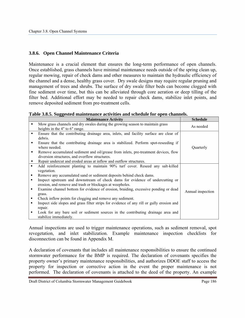
3.8.6. Open Channel Maintenance Criteria Maintenance is a crucial element that ensures the long-term performance of open channels. Once established, grass channels have minimal maintenance needs outside of the spring clean up, regular mowing, repair of check dams and other measures to maintain the hydraulic efficiency of the channel and a dense, healthy grass cover. Dry swale designs may require regular pruning and management of trees and shrubs. The surface of dry swale filter beds can become clogged with fine sediment over time, but this can be alleviated through core aeration or deep tilling of the filter bed. Additional effort may be needed to repair check dams, stabilize inlet points, and remove deposited sediment from pre-treatment cells. Table 3.8.5. Suggested maintenance activities and schedule for open channels.
Maintenance Activity Schedule Mow grass channels and dry swales during the growing season to maintain grass
heights in the 4" to 6" range. As needed
Ensure that the contributing drainage area, inlets, and facility surface are clear of debris.
Ensure that the contributing drainage area is stabilized. Perform spot-reseeding if where needed.
Remove accumulated sediment and oil/grease from inlets, pre-treatment devices, flow diversion structures, and overflow structures.
Repair undercut and eroded areas at inflow and outflow structures.
Quarterly
Add reinforcement planting to maintain 90% turf cover. Reseed any salt-killed vegetation.
Remove any accumulated sand or sediment deposits behind check dams. Inspect upstream and downstream of check dams for evidence of undercutting or
erosion, and remove and trash or blockages at weepholes. Examine channel bottom for evidence of erosion, braiding, excessive ponding or dead
grass. Check inflow points for clogging and remove any sediment. Inspect side slopes and grass filter strips for evidence of any rill or gully erosion and
repair. Look for any bare soil or sediment sources in the contributing drainage area and
stabilize immediately.
Annual inspection
Annual inspections are used to trigger maintenance operations, such as sediment removal, spot revegetation, and inlet stabilization. Example maintenance inspection checklists for disconnection can be found in Appendix M. A declaration of covenants that includes all maintenance responsibilities to ensure the continued stormwater performance for the BMP is required. The declaration of covenants specifies the property owner’s primary maintenance responsibilities, and authorizes DDOE staff to access the property for inspection or corrective action in the event the proper maintenance is not performed. The declaration of covenants is attached to the deed of the property. An example
Chapter 3.8. Open Channel Systems
form is provided at the end of Chapter 5 though variations will exist for scenarios where stormwater crosses property lines. The covenant is between the property and the District Government. It is submitted through the Office of the Attorney General (OAG). All SWMPs have a maintenance agreement stamp that must be signed for a building permit to proceed. A maintenance schedule must appear on the SWMP. Additionally, a maintenance schedule is required in schedule c of the declaration of covenants. Covenants are not required on government properties, but maintenance responsibilities must be defined through a partnership agreement or a memorandum of understanding. Waste material from the repair, maintenance, or removal of a BMP or land cover change shall be removed, and the maintenance contractor shall submit a written report to DDOE within forty-eight (48) hours after disposing of the waste material. The report shall include:
(a) The name, address, phone number, and business license number of the contractor
transporting the waste materials; (b) Date of removal; (c) The address of the BMP; (d) Type of BMP serviced; (e) Amount and type of waste material removed; (f) The name and location of the facility where the waste material was disposed of; and (g) A sworn statement that disposal was in compliance with applicable federal and District
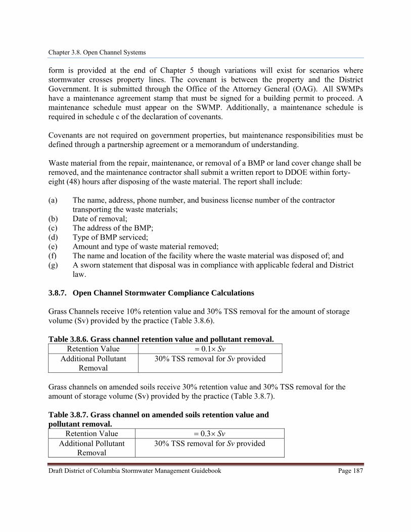
law. 3.8.7. Open Channel Stormwater Compliance Calculations Grass Channels receive 10% retention value and 30% TSS removal for the amount of storage volume (Sv) provided by the practice (Table 3.8.6).
Draft District of Columbia Stormwater Management Guidebook Page 187
SvTable 3.8.6. Grass channel retention value and pollutant removal.
Retention Value = ×1.0 Additional Pollutant
Removal 30% TSS removal for Sv provided
Grass channels on amended soils receive 30% retention value and 30% TSS removal for the amount of storage volume (Sv) provided by the practice (Table 3.8.7). Table 3.8.7. Grass channel on amended soils retention value and pollutant removal.
Retention Value Sv= ×3.0 Additional Pollutant
Removal 30% TSS removal for Sv provided
Chapter 3.8. Open Channel Systems
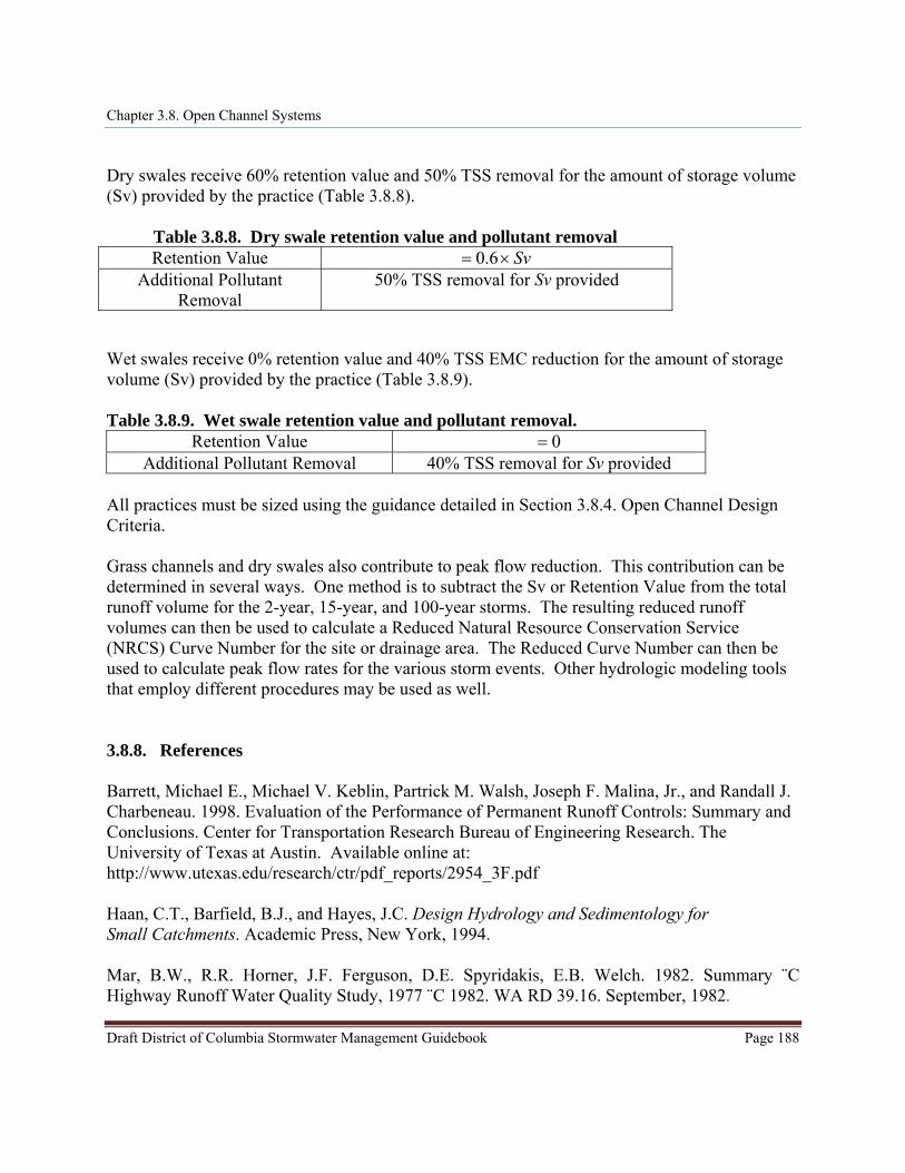
Dry swales receive 60% retention value and 50% TSS removal for the amount of storage volume (Sv) provided by the practice (Table 3.8.8).
Draft District of Columbia Stormwater Management Guidebook Page 188
SvTable 3.8.8. Dry swale retention value and pollutant removal Retention Value = ×6.0
Additional Pollutant Removal
50% TSS removal for Sv provided
Wet swales receive 0% retention value and 40% TSS EMC reduction for the amount of storage volume (Sv) provided by the practice (Table 3.8.9).
Table 3.8.9. Wet swale retention value and pollutant removal.
Retention Value 0= Additional Pollutant Removal 40% TSS removal for Sv provided
All practices must be sized using the guidance detailed in Section 3.8.4. Open Channel Design Criteria. Grass channels and dry swales also contribute to peak flow reduction. This contribution can be determined in several ways. One method is to subtract the Sv or Retention Value from the total runoff volume for the 2-year, 15-year, and 100-year storms. The resulting reduced runoff volumes can then be used to calculate a Reduced Natural Resource Conservation Service (NRCS) Curve Number for the site or drainage area. The Reduced Curve Number can then be used to calculate peak flow rates for the various storm events. Other hydrologic modeling tools that employ different procedures may be used as well. 3.8.8. References Barrett, Michael E., Michael V. Keblin, Partrick M. Walsh, Joseph F. Malina, Jr., and Randall J. Charbeneau. 1998. Evaluation of the Performance of Permanent Runoff Controls: Summary and Conclusions. Center for Transportation Research Bureau of Engineering Research. The University of Texas at Austin. Available online at: http://www.utexas.edu/research/ctr/pdf_reports/2954_3F.pdf Haan, C.T., Barfield, B.J., and Hayes, J.C. Design Hydrology and Sedimentology for Small Catchments. Academic Press, New York, 1994. Mar, B.W., R.R. Horner, J.F. Ferguson, D.E. Spyridakis, E.B. Welch. 1982. Summary ¨C Highway Runoff Water Quality Study, 1977 ¨C 1982. WA RD 39.16. September, 1982.
Chapter 3.8. Open Channel Systems
Draft District of Columbia Stormwater Management Guidebook Page 189
Roanoke Virginia, Stormwater Design Manual. 2008. Stormwater Management Design Manual. Department of Planning Building and Development. Roanoke, Virginia. USDA. 1954. Handbook of Channel of Design for Soil and Water Conservation. Stillwater Outdoor Hydraulic Laboratory and the Oklahoma Agricultural Experiment Station. SCS-TP-61, Washington, DC. Virginia DCR Stormwater Design Specification No. 3: Grass Channels Version 1.8. 2010 . Virginia DCR Stormwater Design Specification No. 10: Dry Swales Version 1.8. 2010 . Virginia DCR Stormwater Design Specification No. 11: Wet Swales Version 1.8. 2010 . Washington State Department of Ecology. 2005. Stormwater Manual for Western Washington. State of Washington Department of Ecology. Available online at: http://www.ecy.wa.gov/programs/wq/stormwater/manual.html
Related Documents