Chapter 3 Chapter 3 Computed Tomography Computed Tomography Stewart C. Bushong Stewart C. Bushong

Chapter 3 Computed Tomography Stewart C. Bushong.
Dec 16, 2015
Welcome message from author
This document is posted to help you gain knowledge. Please leave a comment to let me know what you think about it! Share it to your friends and learn new things together.
Transcript
Chapter 3Chapter 3
Computed TomographyComputed Tomography
Stewart C. BushongStewart C. Bushong
CT GantryCT Gantry
Every CT imager has three Every CT imager has three distinguishing components – the distinguishing components – the operating console, the computer, and operating console, the computer, and the gantry the gantry
The operating console performs two The operating console performs two major functions – imaging control major functions – imaging control with pre-selected technique with pre-selected technique conditions and image viewing and conditions and image viewing and manipulation (window/level)manipulation (window/level)
CT GantryCT Gantry
There may be several operating consoles, There may be several operating consoles, each dedicated to a separate function, each dedicated to a separate function, such as CT control or post-processing and such as CT control or post-processing and image analysis (3D, diffusion/perfusion image analysis (3D, diffusion/perfusion analysis, cardiac scoring, measurements, analysis, cardiac scoring, measurements, region of interest)region of interest)
The CT computer has no physically The CT computer has no physically distinguishing features (it typically looks distinguishing features (it typically looks like any other computer)like any other computer)
CT GantryCT Gantry
The CT computer has high capacity and is The CT computer has high capacity and is very fast due to the large number of very fast due to the large number of computations required on an extensive computations required on an extensive data set – e.g. if there are 750 detectors data set – e.g. if there are 750 detectors and 1500 projections are acquired in 360 and 1500 projections are acquired in 360 degrees of rotation that would equal degrees of rotation that would equal 1,125,000 samples (750 x 1500) for EACH 1,125,000 samples (750 x 1500) for EACH SLICE!!!! Each image at a 1024 x 1024 SLICE!!!! Each image at a 1024 x 1024 matrix requires approximately 2 MB of matrix requires approximately 2 MB of memorymemory
CT GantryCT Gantry
Some CT imagers have the computer Some CT imagers have the computer built into the operating consolebuilt into the operating console
Computers capable of Computers capable of multiprocessing are used in CT multiprocessing are used in CT (multiprocessing means that each (multiprocessing means that each processing unit works on a different processing unit works on a different set of instructions to increase speed set of instructions to increase speed or computing power)or computing power)
CT GantryCT Gantry Multiprocessing allows a computer to Multiprocessing allows a computer to
perform several functions at the same perform several functions at the same time, which reduces reconstruction time time, which reduces reconstruction time and increases capacityand increases capacity
The gantry is special to CT. It houses the The gantry is special to CT. It houses the x-ray source, the detector array, the x-ray source, the detector array, the collimator assembly and a generator. collimator assembly and a generator. Sometimes the generator is attached to Sometimes the generator is attached to the rotating framework along with the the rotating framework along with the tube and detectors. Other times the tube and detectors. Other times the generator is positioned on the floor of the generator is positioned on the floor of the gantry and does not rotategantry and does not rotate
CT GantryCT Gantry
The patient aperture of a CT gantry has a The patient aperture of a CT gantry has a diameter of approximately 70 cm.diameter of approximately 70 cm.
The CT gantry can be tilted in a cephalic or The CT gantry can be tilted in a cephalic or caudal angle plus or minus 30 degrees. caudal angle plus or minus 30 degrees. The capability to tilt is especially useful for The capability to tilt is especially useful for extremity imaging and facial imaging. E.g. extremity imaging and facial imaging. E.g. by having a patient lie prone with their by having a patient lie prone with their head extended, coronal images of the head extended, coronal images of the sinuses may be obtainedsinuses may be obtained
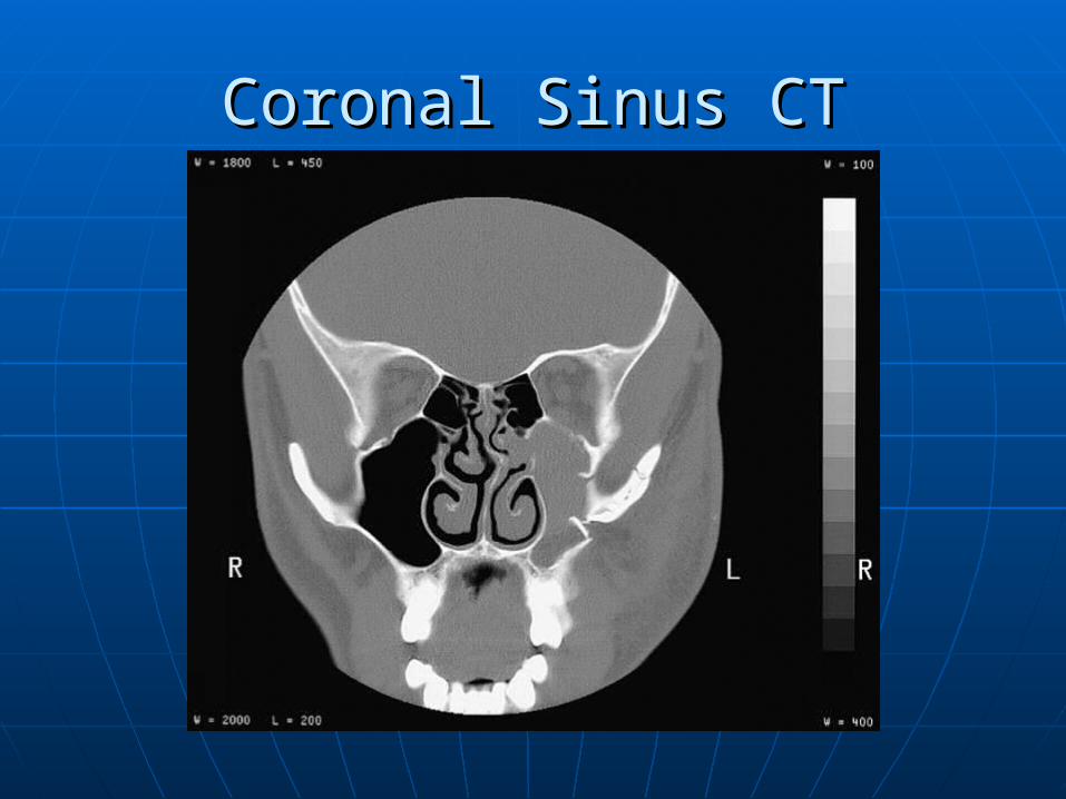
Coronal Sinus CTCoronal Sinus CT
The X-ray SourceThe X-ray Source
CT imaging places two demands on an x-CT imaging places two demands on an x-ray tube – high x-ray intensity and rapid ray tube – high x-ray intensity and rapid heat dissipation.heat dissipation.
High x-ray intensity is accomplished with High x-ray intensity is accomplished with a high mA generator and a generous a high mA generator and a generous focal spot size, up to 2mmfocal spot size, up to 2mm
Rapid heat dissipation is provided by Rapid heat dissipation is provided by large diameter, thick anode disks rotating large diameter, thick anode disks rotating at 10,000 rpmat 10,000 rpm
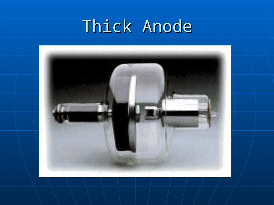
Thick AnodeThick Anode
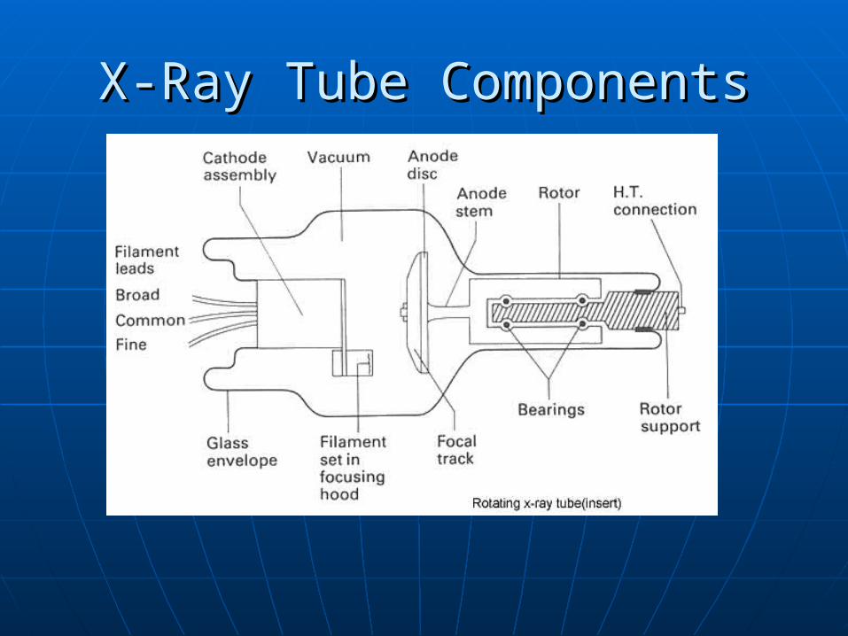
X-Ray Tube ComponentsX-Ray Tube Components

The X-Ray SourceThe X-Ray Source
X-ray tubes developed for CT have X-ray tubes developed for CT have very high heat capacityvery high heat capacity
Anode heat capacity of 6 MHU Anode heat capacity of 6 MHU (million heat units) are common. (million heat units) are common. That compares to less than 1 MHU That compares to less than 1 MHU for general radiography.for general radiography.
The anode-cathode axis is The anode-cathode axis is perpendicular to the patient axis to perpendicular to the patient axis to avoid the avoid the heel effectheel effect
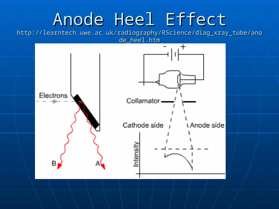
Anode Heel Effect Anode Heel Effect http://learntech.uwe.ac.uk/radiography/RScience/diag_xray_tube/anode_heel.htmhttp://learntech.uwe.ac.uk/radiography/RScience/diag_xray_tube/anode_heel.htm
Anode Heel Effect Anode Heel Effect http://learntech.uwe.ac.uk/radiography/RScience/diag_xray_tube/anode_heel.htmhttp://learntech.uwe.ac.uk/radiography/RScience/diag_xray_tube/anode_heel.htm
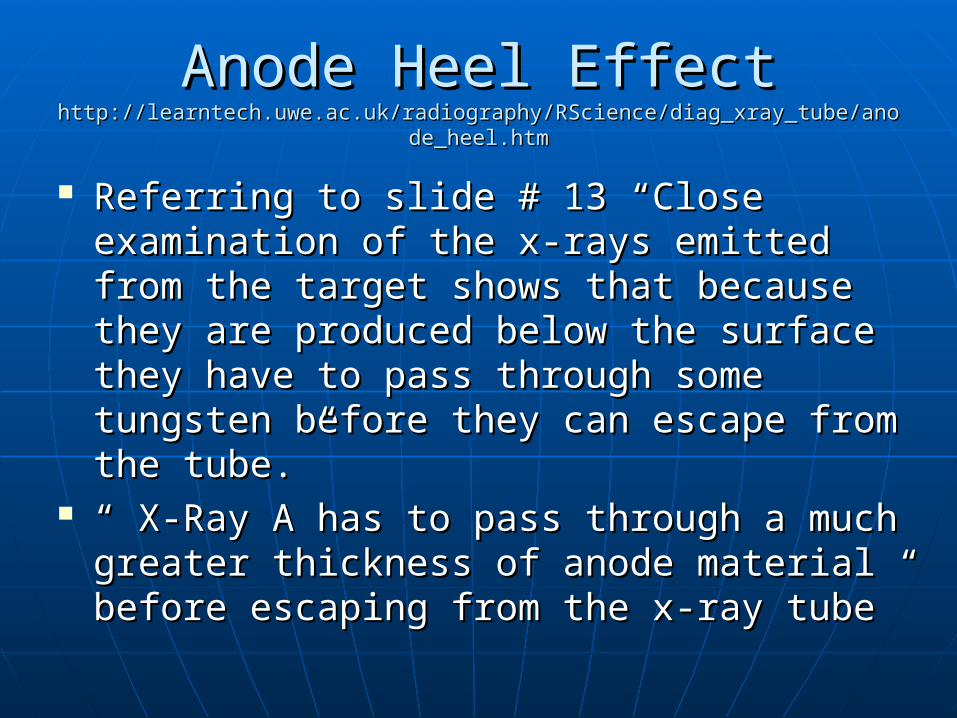
Referring to slide # 13 “Close examination Referring to slide # 13 “Close examination of the x-rays emitted from the target of the x-rays emitted from the target shows that because they are produced shows that because they are produced below the surface they have to pass below the surface they have to pass through some tungsten before they can through some tungsten before they can escape from the tube.”escape from the tube.”
“ “ X-Ray A has to pass through a much X-Ray A has to pass through a much greater thickness of anode material before greater thickness of anode material before escaping from the x-ray tube”escaping from the x-ray tube”

Anode Heel Effect Anode Heel Effect http://learntech.uwe.ac.uk/radiography/RScience/diag_xray_tube/anode_heel.htmhttp://learntech.uwe.ac.uk/radiography/RScience/diag_xray_tube/anode_heel.htm
““X-ray B only has to pass through a X-ray B only has to pass through a small amount of tungsten”small amount of tungsten”
““As the angle of the anode is As the angle of the anode is increased, the anode heel effect increased, the anode heel effect increases”increases”
The X-Ray SourceThe X-Ray Source
Computed tomography x-ray tubes Computed tomography x-ray tubes have high speed (10,000) rpm rotorshave high speed (10,000) rpm rotors
X-ray tube failure is the principle X-ray tube failure is the principle cause of CT imager malfunctioncause of CT imager malfunction
X-ray tube current of 200 to 800 mA X-ray tube current of 200 to 800 mA are common. Too low mA can result are common. Too low mA can result in unacceptable image noise (caused in unacceptable image noise (caused by a lack of sufficient x-rays striking by a lack of sufficient x-rays striking the detectors)the detectors)
The X-Ray SourceThe X-Ray Source
X-ray tube potential is usually 120 kVp to X-ray tube potential is usually 120 kVp to 140 kVp three phase of high frequency140 kVp three phase of high frequency
Such high kVp is used for higher intensity Such high kVp is used for higher intensity and penetrability, and therefore, less x-ray and penetrability, and therefore, less x-ray tube loading and lower patient dose.tube loading and lower patient dose.
Dual focus tubes are common, usually Dual focus tubes are common, usually having .5 and 1.0 mm focal spots, with the having .5 and 1.0 mm focal spots, with the smaller focal spot used for better spatial smaller focal spot used for better spatial resolutionresolution
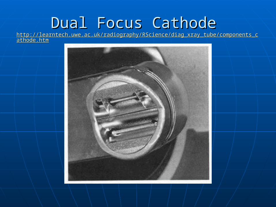
Dual Focus Cathode Dual Focus Cathode http://learntech.uwe.ac.uk/radiography/RScience/diag_xray_tube/components_cathode.htmhttp://learntech.uwe.ac.uk/radiography/RScience/diag_xray_tube/components_cathode.htm
The X-Ray SourceThe X-Ray Source
The improved spatial resolution does not The improved spatial resolution does not result from projection geometry as in result from projection geometry as in radiography, rather from better x-ray radiography, rather from better x-ray beam – radiation detector collimationbeam – radiation detector collimation
Still, the principal effect os spatial Still, the principal effect os spatial resolution is matrix size and field of view resolution is matrix size and field of view (FOV)(FOV)
For third generation CT imagers, the x-ray For third generation CT imagers, the x-ray source is pulsed. Each pulse creates an source is pulsed. Each pulse creates an image projection from each detectorimage projection from each detector
The X-Ray SourceThe X-Ray Source
When pulsed, up to 100 mA is used When pulsed, up to 100 mA is used with pulse widths of 1 to 5 ms at with pulse widths of 1 to 5 ms at pulse repetition rates of 60 Hzpulse repetition rates of 60 Hz
For fourth generation imagers the x-For fourth generation imagers the x-ray tube is energized continuouslyray tube is energized continuously
Each pass of a fourth generation fan Each pass of a fourth generation fan beam over a detector produces an beam over a detector produces an image projectionimage projection
The X-Ray SourceThe X-Ray Source
Computed tomography x-ray beam are Computed tomography x-ray beam are filtered to harden the beam and make filtered to harden the beam and make it more unifrom at the detector arrayit more unifrom at the detector array
Filtration produces a higher energy, Filtration produces a higher energy, more homogeneous x-ray beam and more homogeneous x-ray beam and reduces the beam hardening artifactreduces the beam hardening artifact
A shaped x-ray beam filter is used in A shaped x-ray beam filter is used in CT to produce a more uniform CT to produce a more uniform intensity at the detector arrayintensity at the detector array
The X-Ray SourceThe X-Ray Source
A “bow tie” filter is often used to A “bow tie” filter is often used to even radiation intensity at the even radiation intensity at the detector arraydetector array
High Voltage GeneratorHigh Voltage Generator
High kVp is used to minimize High kVp is used to minimize photoelectric absorption and, photoelectric absorption and, therefore, patient dosetherefore, patient dose
High kVp is used to reduce bone High kVp is used to reduce bone attenuation relative to soft tissue attenuation relative to soft tissue allowing a wider dynamic range of the allowing a wider dynamic range of the imageimage
High kVp is used to increase radiation High kVp is used to increase radiation intensity at the detector arrayintensity at the detector array
High Voltage GeneratorHigh Voltage Generator
High kVp is used to reduce x-ray tube High kVp is used to reduce x-ray tube loading, and thereby , extend tube lifeloading, and thereby , extend tube life
Three phase or high frequency voltage Three phase or high frequency voltage generation is used for CT imagersgeneration is used for CT imagers
Three phase voltage is usually generated Three phase voltage is usually generated by a stand alone module near the gantry. by a stand alone module near the gantry. Cables that will only wind 360 degree Cables that will only wind 360 degree must be used, causing a reversal of gantry must be used, causing a reversal of gantry positionposition
High Voltage GeneratorHigh Voltage Generator
High frequency generators are small High frequency generators are small enough that they can be mounted on enough that they can be mounted on the rotating gantrythe rotating gantry
Heat units and joules are equivalent Heat units and joules are equivalent measure of energymeasure of energy
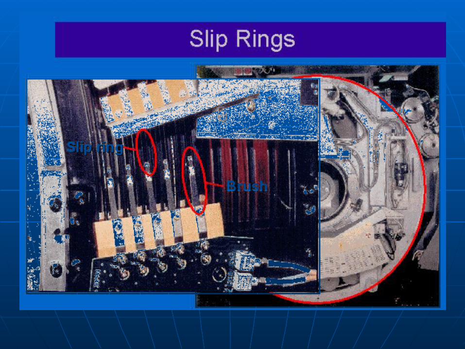
Slip rings make possible continuous Slip rings make possible continuous rotation of the x-ray source leading rotation of the x-ray source leading to spiral CTto spiral CT
High Voltage GeneratorHigh Voltage Generator
Slip rings incorporate circular electrical Slip rings incorporate circular electrical conductors, one type of which rotates and conductors, one type of which rotates and passes power to the high-voltage passes power to the high-voltage generator; the other passes signals from generator; the other passes signals from the data acquisition system to the the data acquisition system to the computer: further explanation can be computer: further explanation can be found at found at http://www.amershamhealth.com/medcyclhttp://www.amershamhealth.com/medcyclopaedia/medical/Volume%20I/SLIP%20RINopaedia/medical/Volume%20I/SLIP%20RING%20TECHNOLOGY.ASPG%20TECHNOLOGY.ASP
High Voltage GeneratorHigh Voltage Generator
Essentially all CT imager now use high Essentially all CT imager now use high frequency generatorsfrequency generators• Three phase power was used until the mid Three phase power was used until the mid
1980’s1980’s The high frequency generator can be The high frequency generator can be
positioned on the rotating gantry with the x-positioned on the rotating gantry with the x-ray sourceray source
The high frequency generator can be The high frequency generator can be positioned on the fixed part of the gantry and positioned on the fixed part of the gantry and connected to the x-ray source through slip connected to the x-ray source through slip ringsrings
High Voltage GeneratorHigh Voltage Generator
The DAS is located between the The DAS is located between the detector array and the computerdetector array and the computer
The DAS The DAS • Amplifies the detector signalAmplifies the detector signal• Converts the analog signal to digitalConverts the analog signal to digital• Transmits the digital signal to the computerTransmits the digital signal to the computer
High frequency generator voltage High frequency generator voltage generation eliminated the need for generation eliminated the need for massive high-voltage transformersmassive high-voltage transformers
Detector ArrayDetector Array
The evolution of the CT radiation detector The evolution of the CT radiation detector has progressed with continuous has progressed with continuous improvementsimprovements
Detector efficiency is important because it Detector efficiency is important because it determines maximum tube loading and determines maximum tube loading and controls patient dosecontrols patient dose
Three important features of the detector Three important features of the detector array are efficiency, number of detectors, array are efficiency, number of detectors, and detector concentrationand detector concentration
Detector ArrayDetector Array
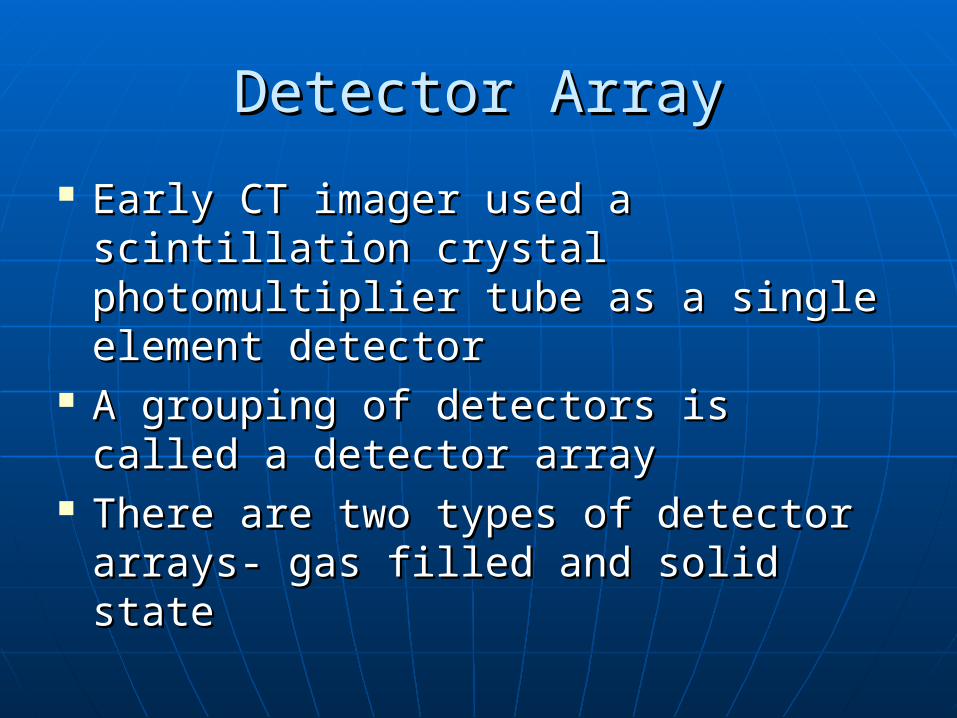
Early CT imager used a scintillation Early CT imager used a scintillation crystal photomultiplier tube as a crystal photomultiplier tube as a single element detectorsingle element detector
A grouping of detectors is called a A grouping of detectors is called a detector arraydetector array
There are two types of detector There are two types of detector arrays- gas filled and solid statearrays- gas filled and solid state
Detector ArrayDetector Array
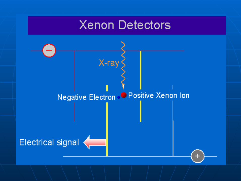
Gas filled detectors – high pressure Gas filled detectors – high pressure xenon – have very fast response and no xenon – have very fast response and no afterglow but only about 50% detection afterglow but only about 50% detection efficiencyefficiency
Gas filled detectors can be packed more Gas filled detectors can be packed more tightly than solid state detectors with less tightly than solid state detectors with less interspace septainterspace septa
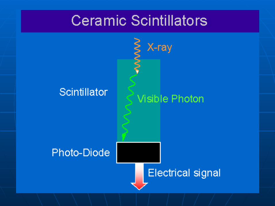
Most solid state detectors today use a Most solid state detectors today use a scintillator, cadmium tungstate, optically scintillator, cadmium tungstate, optically coupled to a photodiodecoupled to a photodiode
Detector ArrayDetector Array
Solid state detectors have nearly 100% Solid state detectors have nearly 100% detection efficiency but cannot be tightly detection efficiency but cannot be tightly packedpacked
The detector array consists of many The detector array consists of many individual detector fashioned as a module individual detector fashioned as a module that are positioned on a receptor board for that are positioned on a receptor board for easy exchange and serviceeasy exchange and service
A gas filled detector array uses small ion A gas filled detector array uses small ion chamber filled with high-pressure xenon or chamber filled with high-pressure xenon or other gasother gas
Detector ArrayDetector Array
Each ion chamber is about 1 mm wide with Each ion chamber is about 1 mm wide with essentially no interspaceessentially no interspace
The geometric efficiency – the percent The geometric efficiency – the percent area of the detector array that is detector, area of the detector array that is detector, not interspace – is more than 90%not interspace – is more than 90%
The intrinsic detection efficiency for high The intrinsic detection efficiency for high pressure xenon is approximately 50%pressure xenon is approximately 50%
Total detector efficiency = geometric Total detector efficiency = geometric efficiency x intrinsic efficiencyefficiency x intrinsic efficiency
Detector ArrayDetector Array
Solid state detectors are made of a Solid state detectors are made of a scintillation crystal, which when scintillation crystal, which when irradiated emits light that is irradiated emits light that is converted to an analog signal by a converted to an analog signal by a photodiodephotodiode
Solid state detectors have Solid state detectors have approximately 90% intrinsic approximately 90% intrinsic detection efficiency. Essentially, all detection efficiency. Essentially, all incident x-rays are detectedincident x-rays are detected
Detector ArrayDetector Array
Total detection efficiency depends on Total detection efficiency depends on the number of detectors and how the number of detectors and how tightly they are packedtightly they are packed
When there is interspace between When there is interspace between detectors, detection efficiency is detectors, detection efficiency is reduced and patient dose increasedreduced and patient dose increased
Eighty percent total detection Eighty percent total detection efficiency is common for solid state efficiency is common for solid state detector arraysdetector arrays
Detector ArrayDetector Array
Solid state detectors are Solid state detectors are automatically recalibrated between automatically recalibrated between scansscans
Solid state detectors are more Solid state detectors are more expensive than gas-filled detectors expensive than gas-filled detectors and their increased efficiency can and their increased efficiency can result in less x-ray tube loading, result in less x-ray tube loading, reduced image noise and reduced reduced image noise and reduced patient dosepatient dose
Detector ArrayDetector Array
The DAS is positioned just after the The DAS is positioned just after the detector array to amplify each signal, detector array to amplify each signal, convert each signal to digital form, and convert each signal to digital form, and properly sequence each signal to the properly sequence each signal to the computercomputer
Multiple detector array allow the Multiple detector array allow the collection of two or more image data sets collection of two or more image data sets simultaneouslysimultaneously
Multiple detector arrays can reduce the Multiple detector arrays can reduce the heat loading of the x-ray tubeheat loading of the x-ray tube
Detector ArrayDetector Array
Multiple detector arrays allow Multiple detector arrays allow simultaneous imaging of two or more simultaneous imaging of two or more slicesslices
Collimator AssemblyCollimator Assembly
There are two collimator in CT – pre-There are two collimator in CT – pre-patient and post-patientpatient and post-patient
The pre-patient collimator is positioned The pre-patient collimator is positioned near the x-ray sourcenear the x-ray source
The pre-patient collimator controls the The pre-patient collimator controls the patient dose and determines the dose patient dose and determines the dose profileprofile
As the pre-patient collimator is narrowed, As the pre-patient collimator is narrowed, patient dose increases and the dose patient dose increases and the dose profile becomes roundedprofile becomes rounded
Collimator Assembly Collimator Assembly
pre-patient collimation controls slice pre-patient collimation controls slice thicknessthickness
The dose profile is a plot of dose The dose profile is a plot of dose across the slice thicknessacross the slice thickness
The dose profile should be square but The dose profile should be square but is rounded because of scatter is rounded because of scatter radiationradiation
The post-patient collimator controls The post-patient collimator controls the slice thickness (sensitivity profile)the slice thickness (sensitivity profile)

Collimator AssemblyCollimator Assembly
When the post-patient collimators When the post-patient collimators are narrowed, slice thickness is are narrowed, slice thickness is reducedreduced
Sensitivity profile is a plot of detector Sensitivity profile is a plot of detector response versus distance (mm)response versus distance (mm)
The ideal sensitivity profile is square; The ideal sensitivity profile is square; in practice, it is rounded because of in practice, it is rounded because of scatter radiation.scatter radiation.
Collimator AssemblyCollimator Assembly pre-patient and post-patient collimators pre-patient and post-patient collimators
are controlled together to match dose are controlled together to match dose profile and sensitivity profileprofile and sensitivity profile
If dose profile exceeds sensitivity profile, If dose profile exceeds sensitivity profile, the patient dose is excessivethe patient dose is excessive
If sensitivity profile exceeds dose profile, If sensitivity profile exceeds dose profile, image quality is compromisedimage quality is compromised
Nominal slice thickness is controllable Nominal slice thickness is controllable between 1 and 10mm (sub-millimeter between 1 and 10mm (sub-millimeter scanning is available on newer multi-slice scanning is available on newer multi-slice system) system)
Collimator AssemblyCollimator Assembly
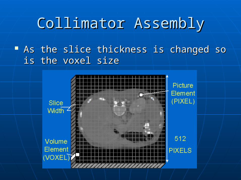
As the slice thickness is changed so is the As the slice thickness is changed so is the voxel sizevoxel size

Collimator AssemblyCollimator Assembly
Thinner slices are required for rapidly Thinner slices are required for rapidly changing anatomy, for example, the inner changing anatomy, for example, the inner earear
Thinner slices result in improved spatial Thinner slices result in improved spatial resolutionresolution
Thinner slices result in higher patient dose Thinner slices result in higher patient dose because of increase overlap of slicesbecause of increase overlap of slices
When imaging with thin slices they are When imaging with thin slices they are usually contiguous so that no tissue is usually contiguous so that no tissue is missedmissed
Collimator AssemblyCollimator Assembly
High voltage slip rings are oil insulated High voltage slip rings are oil insulated and transfer power from an external high and transfer power from an external high voltage generator to the gantryvoltage generator to the gantry
Low voltage slip rings are air insulated and Low voltage slip rings are air insulated and transfer data from gantry to computertransfer data from gantry to computer
When a spiral (helical) CT is based on low When a spiral (helical) CT is based on low voltage slip rings, the high voltage voltage slip rings, the high voltage generator is high frequency type and generator is high frequency type and mounted on the rotating gantrymounted on the rotating gantry

Collimator AssemblyCollimator Assembly
Please refer to page 31 of your Please refer to page 31 of your textbook for a nice example of how textbook for a nice example of how all the CT Gantry parts fit together.all the CT Gantry parts fit together.

SourcesSources Computed Tomography: physical Computed Tomography: physical
principles… – Seeramprinciples… – Seeram Helical Scanning – BlanckHelical Scanning – Blanck Introduction to Computed Tomography – Introduction to Computed Tomography –
RomansRomans Computed Tomography – Bushong Computed Tomography – Bushong http://www.impactscan.org/slides/xrayct/inhttp://www.impactscan.org/slides/xrayct/in
dex.htmdex.htm http://learntech.uwe.ac.uk/radiography/RShttp://learntech.uwe.ac.uk/radiography/RS
cience/diag_xray_tube/d_xray_contents.htcience/diag_xray_tube/d_xray_contents.htmm
Related Documents