“Studies on Radial Tipped Centrifugal Fan” 110 CHAPTER – 3 CENTRIFUGAL FAN DESIGN METHODOLOGIES 3.1 Introduction Centrifugal fans and blowers are the turbo machines widely used in present industrial and domestic life. It is important to recognize that the design of any turbo machine is an interdisciplinary process, involving aerodynamics, thermodynamics, fluid dynamics, stress analysis, vibration analysis, the selection of materials, and the requirements for manufacturing. Though centrifugal fans have been developed as highly efficient machines, design is still based on various empirical and semi empirical rules proposed by fan designers. Manufacturing industries of fans and blowers seldom followed optimum design solution for individual fan/blower. Mostly their design and fabrication is based on series of successful past models or derived from fan laws and geometrical similarities. During extensive literature review on design and performance evaluation of pumps, blowers and fans, it is observed that much research work has been carried out on local flow physics, aerodynamics and phenomena of energy transfer. Designing of these turbo machines requires computation with many variables and coefficients. It is also studied that the design methodologies suggested by different researchers differ widely. It has revealed lacuna of explicit design methodology which can give desired performance. One of the objectives of present study is to design and analyze performance of explicit design methodologies as suggested in literature. Three systematic design methodologies for centrifugal fan are traced out after comprehensive literature review. Focusing on these three design methods, comparative assessment is made mathematically and then experiments are carried out to get optimum design solution. These design methodologies are summarized as under and discussed in detail subsequently. 3.2 Input Parameters for Centrifugal Fan Design This research work is based on an industrial requirement for Fume Extraction Fan of SDS-9 texturising machine. Here variable flow is required at constant head

Welcome message from author
This document is posted to help you gain knowledge. Please leave a comment to let me know what you think about it! Share it to your friends and learn new things together.
Transcript

“Studies on Radial Tipped Centrifugal Fan” 110
CHAPTER – 3
CENTRIFUGAL FAN DESIGN METHODOLOGIES
3.1 Introduction
Centrifugal fans and blowers are the turbo machines widely used in present
industrial and domestic life. It is important to recognize that the design of any turbo
machine is an interdisciplinary process, involving aerodynamics, thermodynamics,
fluid dynamics, stress analysis, vibration analysis, the selection of materials, and the
requirements for manufacturing.
Though centrifugal fans have been developed as highly efficient machines,
design is still based on various empirical and semi empirical rules proposed by fan
designers. Manufacturing industries of fans and blowers seldom followed optimum
design solution for individual fan/blower. Mostly their design and fabrication is based
on series of successful past models or derived from fan laws and geometrical
similarities.
During extensive literature review on design and performance evaluation of
pumps, blowers and fans, it is observed that much research work has been carried out
on local flow physics, aerodynamics and phenomena of energy transfer. Designing of
these turbo machines requires computation with many variables and coefficients. It is
also studied that the design methodologies suggested by different researchers differ
widely. It has revealed lacuna of explicit design methodology which can give desired
performance.
One of the objectives of present study is to design and analyze performance of
explicit design methodologies as suggested in literature. Three systematic design
methodologies for centrifugal fan are traced out after comprehensive literature review.
Focusing on these three design methods, comparative assessment is made
mathematically and then experiments are carried out to get optimum design solution.
These design methodologies are summarized as under and discussed in detail
subsequently.
3.2 Input Parameters for Centrifugal Fan Design
This research work is based on an industrial requirement for Fume Extraction
Fan of SDS-9 texturising machine. Here variable flow is required at constant head
Chapter – 3: Centrifugal Fan Design Methodologies
“Studies on Radial Tipped Centrifugal Fan” 111
under dust laden conditions. Radial blades are ideal for dust laden air or gas because
they are less prone to blockage, dust erosion and failure and have self cleaning
properties as observed by Mohamed Ali [20]. It has ideal zero slope in H-Q (head-
discharge) curve to give variable discharge at constant head [9]. R. Ajithkumar [22]
observed that the advantages of radial fans and blowers are having more stable
operating range, ease of manufacturing with lower manufacturing and maintenance
cost and high pressure development per stage. Wosika L. R. [37] has experimentally
verified superior performance of radial vaned impellers.
Radial blades have lower unit blade stress for a given diameter and rotational
speed hence lighter in weight. There is equal energy conversion in impeller and
diffuser so it gives high-pressure ratio with good efficiency [9, 20]. Looking to these
realization and facts radial blade fan is selected for this study.
The input parameters for the design of radial tipped centrifugal fan for fume
extraction from SDS-9 texturing machine are summarized below.
Flow Discharge Q = 0.5 m3/s
Static Suction Pressure = -196.4 N/m2
Static Delivery Pressure = 784.8 N/m2
Static Pressure Gradient ΔPs = 981.2 Pa
Speed of impeller rotation N = 2800 rpm
Air Density = 1.165 kg/m3
Optimized number of blades z = 16 [135]
Outlet Blade Angle β2 = 90°
Suction Temperature Ts = 30 °C = 303 K
Atmospheric Pressure Patm = 1.01325 x 10⁵ Pa
Atmospheric Temperature Tatm = 30° C = 303° K
These parameters are kept identical for each design methodology prescribed
here in.
3.3 Design of Radial Tipped Centrifugal Fan as per Fundamental Concepts
[9, 10, 14, 28]
This design procedure is based on the fundamental principles of fluid flow
with continuity and energy equations. The design follows the path from suction to
discharge. To accelerate the flow at impeller inlet, converging section is designed
Chapter – 3: Centrifugal Fan Design Methodologies
“Studies on Radial Tipped Centrifugal Fan” 112
after inlet duct. Energy balance is established at fan inlet, intermediate stage of
impeller and outlet stage of volute/scroll casing.
During this process stage velocity, pressure and discharge at different stages
are calculated. Flat front and back shrouds are selected for ease of impeller
fabrication. Design procedure and calculations for above referred input parameters are
presented below:
3.3.1 Design of Impeller
3.3.1.1 Impeller eye and inlet duct size
Let inlet duct size be 10% higher than impeller eye size or impeller inlet
diameter. This will make conical insertion of inlet duct and flow acceleration at
impeller eye or inlet.
1.1 1.1
Assuming no loss during 90º turning from eye inlet to impeller inlet, the eye
inlet velocity vector will remain same as absolute velocity vector at the entry of
impeller.
. .
Further let tangential velocity component be 10% higher than axial velocity
component for better induction of flow.
So, Inlet Tip velocity
1.1 1.1
, 4
4
4
60 1.1
60 1.14
Here Q=0.5 m3/s and speed of impeller rotation N=2800 rpm,
∴Impeller Inlet Diameter
D1=0.168 m = Deye
Peripheral speed at inlet
Chapter – 3: Centrifugal Fan Design Methodologies
“Studies on Radial Tipped Centrifugal Fan” 113
60 24.63m/s 1.1
22.45 m/s
1.1 1.1 0.168 0.185 185
24.63 22.45 33.37 /
3.3.1.2 Impeller inlet blade angle (Refer Figure 3.5 for inlet velocity triangle)
tan22.4524.63
42.35°
3.3.1.3 Impeller width at inlet
Here Z=16 and assumed blade thickness t = 2 mm
0.5 0.168 16 2 10 22.45
0.045 45
3.3.1.4 Impeller outlet parameters
The Fan Power =∆ 981.2 0.5 490.6
Considering 10% extra to accommodate flow recirculation and impeller exit
hydraulic losses.
So 1.1 1.1 490.6 539.66
,
Specific ,539.66
1.165 0.5 926.45 / kg ⁄ s
0.8 (Assuming slip factor = 0.8 for radial blades) [9]
539.66 1.165 0.5 0.8
34.03 /
0.8 34.03 27.22 /
60
0.232
Taking width of blade at inlet = outlet blade width

Chapter – 3: Centrifugal Fan Design Methodologies
“Studies on Radial Tipped Centrifugal Fan” 114
0.5 0.232 16 2 10 0.045
16 /
U 0.2 6.81 /
0.2
6.81 16 17.39 /
√27.22 16 31.58 /
tan16
27.22 0.59
30.45°
(Refer Figure 3.5 for outlet velocity triangle)
3.3.2 Design of Volute Casing
Analyzing steady flow energy equation at inlet and exit: 12 W
12
Neglecting potential difference,
22
2 981.21.165 22.45 2 926.45
Hence casing outlet velocity, V4 25.93 m/s
Where Av is Exit area of volute casing =
Allowing for 5 mm radial clearance between impeller and volute tongue,
2 5232
2 5 121
2 121 242
Width of volute casing (bv) is normally 2 to 3 times b1 [26]
Let us take it 2.5 times. Hence
2.5 2.5 45 112.5
0.5 25.93
Chapter – 3: Centrifugal Fan Design Methodologies
“Studies on Radial Tipped Centrifugal Fan” 115
0.5 0.1125 0.121 25.93
292
2 292 584
Now incremental volute angle with respect to increase in radius of casing
360 ∆
∆ ° °
0.121 360 0.292 0.121
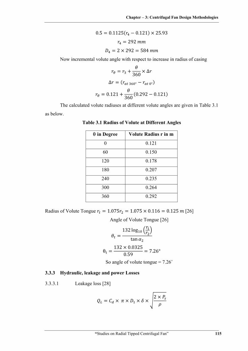
The calculated volute radiuses at different volute angles are given in Table 3.1
as below.
Table 3.1 Radius of Volute at Different Angles
θ in Degree Volute Radius r in m
0 0.121
60 0.150
120 0.178
180 0.207
240 0.235
300 0.264
360 0.292
Radius of Volute Tongue 1.075 1.075 0.116 0.125 [26]
Angle of Volute Tongue [26]
132 log
tan
θ132 0.0325
0.59 7.26°
So angle of volute tongue = 7.26˚
3.3.3 Hydraulic, leakage and power Losses
3.3.3.1 Leakage loss [28]
2

Chapter – 3: Centrifugal Fan Design Methodologies
“Studies on Radial Tipped Centrifugal Fan” 116
,23 ∆
And coefficient of discharge Cd is 0.6 to 0.7,
2 requirements.
0.6 0.169 0.0022 2
3 981.21.165
0.0213 /
3.3.3.2 Suction pressure loss [28]
Where ki is a loss factor probably of the order of 0.5 to 0.8
12 0.65 1.165 22.45
190.76
3.3.3.3 Impeller pressure loss [28]
12
At design point of maximum efficiency kii is in order of 0.2 – 0.3 for sheet
metal blades and rather less for aerofoil section. Selecting 0.25,
0.2512 1.165 33.37 17.39
37.18
3.3.3.4 Volute pressure loss [28]
12
kiii is of the order of 0.4 and will vary with deviation from design conditions.
0.412 1.165 31.58 25.98
7.23 3.3.3.5 Disc friction loss [28]
5⁄
5
Where f is material friction factor in order of 0.005 for mild steel sheet metal [28]
Chapter – 3: Centrifugal Fan Design Methodologies
“Studies on Radial Tipped Centrifugal Fan” 117
0.005 1.16534.030.116
0.1165
0.0066
Hence, Power loss due to Disc friction 2
602 2800 0.0066
60 1.94
3.3.4 Efficiencies
3.3.4.1 Hydraulic efficiency
∆∆
981.2981.2 196.13 43.47 10.58 0.8065
80.65%
3.3.4.2 Volumetric efficiency
0.50.5 0.0213 0.959
95.9%
3.3.4.3 Total efficiency
0.8065 0.959 0.7736
77.36%
3.3.5 Ideal shaft power required to run the fan
∆
981.2 196.13 43.47 10.58 0.5 0.02130.7736 1.94
821.7
,821.7 602 2800
2.804
3.3.6 Shaft diameter [136]
16
Chapter – 3: Centrifugal Fan Design Methodologies
“Studies on Radial Tipped Centrifugal Fan” 118
16 2.804 4343 10 0.0119 11.9
3.3.7 Blade profile
Blade Profile is made by tangent arc method [26]. When this method is used,
the impeller is divided into a number of assumed concentric rings, not necessarily
equally spaced between inner and outer radii. The radius Rb of the arc is defining the
blade shape between inner and outer radii.
2 cos cos
12
0.2322
0.1682
0.1682 cos 42.27 0
0.0512 51.2
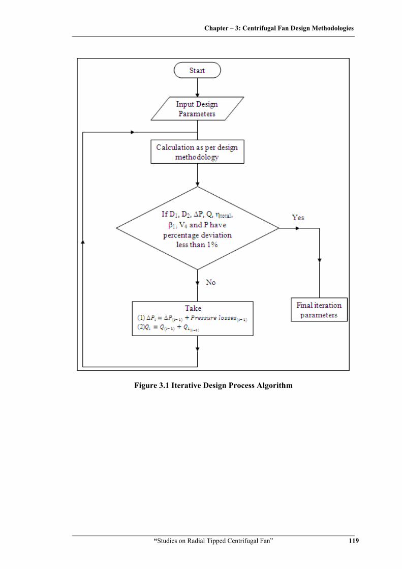
After obtaining preliminary dimension of fan based on input data, further iterations
are made to get optimum design parameters. Next stage of iteration is made after
adding leakage and pressure losses of previous iteration in required design point
discharge and pressure head across the impeller stage as given in input data. This is
done to accommodate possible hydraulic, discharge and power losses at different flow
passages. This process is carried out till there is no marginal dimensional change in
impeller outer diameter and other important parameters. Figure 3.1 shows iterative
design procedure algorithm. Summary of designed calculation including few
iterations are given in Table 3.2, while Figure 3.2 to 3.5 gives dimensional drawings
of the fan designed as per fundamental design.
The Matlab program has been developed for this design calculation and is
given in Annexure A.
Chapter – 3: Centrifugal Fan Design Methodologies
“Studies on Radial Tipped Centrifugal Fan” 119
Figure 3.1 Iterative Design Process Algorithm
Chapter – 3: Centrifugal Fan Design Methodologies
“Studies on Radial Tipped Centrifugal Fan” 120
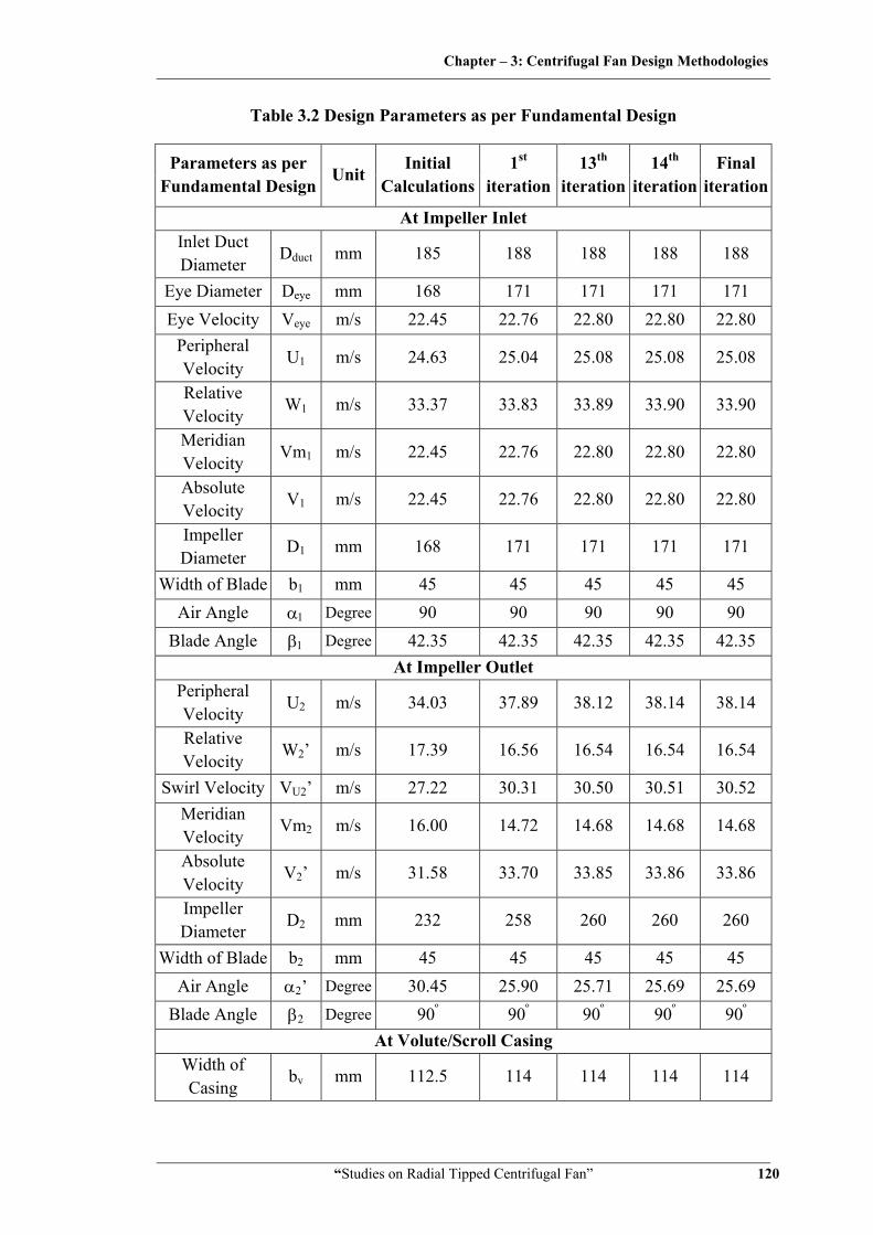
Table 3.2 Design Parameters as per Fundamental Design
Parameters as per Fundamental Design
Unit Initial
Calculations1st
iteration13th
iteration 14th
iteration Final
iteration
At Impeller Inlet Inlet Duct Diameter
Dduct mm 185 188 188 188 188
Eye Diameter Deye mm 168 171 171 171 171 Eye Velocity Veye m/s 22.45 22.76 22.80 22.80 22.80
Peripheral Velocity
U1 m/s 24.63 25.04 25.08 25.08 25.08
Relative Velocity
W1 m/s 33.37 33.83 33.89 33.90 33.90
Meridian Velocity
Vm1 m/s 22.45 22.76 22.80 22.80 22.80
Absolute Velocity
V1 m/s 22.45 22.76 22.80 22.80 22.80
Impeller Diameter
D1 mm 168 171 171 171 171
Width of Blade b1 mm 45 45 45 45 45 Air Angle α1 Degree 90 90 90 90 90
Blade Angle β1 Degree 42.35 42.35 42.35 42.35 42.35 At Impeller Outlet
Peripheral Velocity
U2 m/s 34.03 37.89 38.12 38.14 38.14
Relative Velocity
W2’ m/s 17.39 16.56 16.54 16.54 16.54
Swirl Velocity VU2’ m/s 27.22 30.31 30.50 30.51 30.52 Meridian Velocity
Vm2 m/s 16.00 14.72 14.68 14.68 14.68
Absolute Velocity
V2’ m/s 31.58 33.70 33.85 33.86 33.86
Impeller Diameter
D2 mm 232 258 260 260 260
Width of Blade b2 mm 45 45 45 45 45 Air Angle α2’ Degree 30.45 25.90 25.71 25.69 25.69
Blade Angle β2 Degree 90º 90º 90º 90º 90º At Volute/Scroll Casing
Width of Casing
bv mm 112.5 114 114 114 114
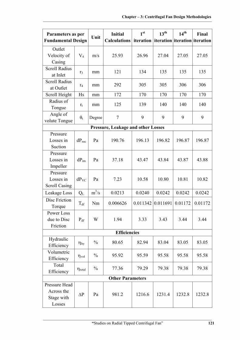
Chapter – 3: Centrifugal Fan Design Methodologies
“Studies on Radial Tipped Centrifugal Fan” 121
Parameters as per Fundamental Design
Unit Initial
Calculations1st
iteration13th
iteration 14th
iteration Final
iteration
Outlet Velocity of
Casing V4 m/s 25.93 26.96 27.04 27.05 27.05
Scroll Radius at Inlet
r3 mm 121 134 135 135 135
Scroll Radius at Outlet
r4 mm 292 305 305 306 306
Scroll Height Hs mm 172 170 170 170 170 Radius of Tongue
rt mm 125 139 140 140 140
Angle of volute Tongue
θt Degree 7 9 9 9 9
Pressure, Leakage and other Losses Pressure Losses in Suction
dPsuc Pa 190.76 196.13 196.82 196.87 196.87
Pressure Losses in Impeller
dPim Pa 37.18 43.47 43.84 43.87 43.88
Pressure Losses in
Scroll Casing dPVC Pa 7.23 10.58 10.80 10.81 10.82
Leakage Loss QL m3/s 0.0213 0.0240 0.0242 0.0242 0.0242 Disc Friction
Torque Tdf Nm 0.006626 0.011342 0.011691 0.01172 0.01172
Power Loss due to Disc
Friction Pdf W 1.94 3.33 3.43 3.44 3.44
Efficiencies Hydraulic Efficiency ηhy % 80.65 82.94 83.04 83.05 83.05
Volumetric Efficiency ηvol % 95.92 95.59 95.58 95.58 95.58
Total Efficiency ηtotal % 77.36 79.29 79.38 79.38 79.38
Other Parameters Pressure Head
Across the Stage with
Losses
ΔP Pa 981.2 1216.6 1231.4 1232.8 1232.8

Chapter – 3: Centrifugal Fan Design Methodologies
“Studies on Radial Tipped Centrifugal Fan” 122
Parameters as per Fundamental Design
Unit Initial
Calculations1st
iteration13th
iteration 14th
iteration Final
iteration
Flow Discharge with
Losses Q m3/s 0.500 0.521 0.524 0.524 0.524
Blade Profile Radius
Rb mm 51.2 74.5 75.8 75.9 75.9
Shaft Diameter Ds mm 11.9 11.8 11.8 11.8 11.8 Power
Required to Run Fan
P W 821.7 817.2 817.5 817.5 817.5
Figure 3.2 Blade Profile as per Fundamental Design
Figure 3.3 Impeller and Volute Casing Assembly as per Fundamental Design
Chapter – 3: Centrifugal Fan Design Methodologies
“Studies on Radial Tipped Centrifugal Fan” 123
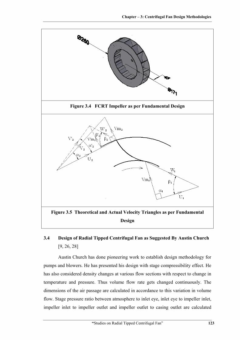
Figure 3.4 FCRT Impeller as per Fundamental Design
Figure 3.5 Theoretical and Actual Velocity Triangles as per Fundamental
Design
3.4 Design of Radial Tipped Centrifugal Fan as Suggested By Austin Church
[9, 26, 28]
Austin Church has done pioneering work to establish design methodology for
pumps and blowers. He has presented his design with stage compressibility effect. He
has also considered density changes at various flow sections with respect to change in
temperature and pressure. Thus volume flow rate gets changed continuously. The
dimensions of the air passage are calculated in accordance to this variation in volume
flow. Stage pressure ratio between atmosphere to inlet eye, inlet eye to impeller inlet,
impeller inlet to impeller outlet and impeller outlet to casing outlet are calculated

Chapter – 3: Centrifugal Fan Design Methodologies
“Studies on Radial Tipped Centrifugal Fan” 124
individually. Church has used trapezoidal section which is difficult to fabricate for a
single fan. Hence volute casing is designed as per principles of fundamental design as
described earlier.
3.4.1 Effect of compressibility on design
In a centrifugal fan, air is compressible working fluid. If flow is steady, mass
flow remains constant but density changes with respect to temperature and pressure.
Hence volume flow Q gets changed. Taking compressibility effect into consideration:
Characteristic equation of gas is,
. ,
1.01325 10287 303 1.1652
, 0.5 1.165 0.58259 /
3.4.2 Design of impeller
3.4.2.1 Impeller eye and inlet duct size
Assuming duct velocity at suction Vduct =16 m/s [26]
So, Diameter of suction duct
D4
4 0.516
0.199
The standard suction flange sizes are -1, 1.25, 1.5, 2, 2.5, 3, 4, 5, 6, 8, 10, 12,
14, 16, 18 inch, Hence selecting Diameter of suction flange before duct Dsuction = 8
inch = 203 mm
Taking impeller eye velocity Veye slightly higher than suction velocity= 18 m/s
[26]
2
182 9.81 16.51
, P P 101325 196.5

Chapter – 3: Centrifugal Fan Design Methodologies
“Studies on Radial Tipped Centrifugal Fan” 125
1.01128.6 10
101128.6101325 0.9981
, .
303 0.9981 .
302.83
, ,
1.011286 10287 302.83
1.1636 /
0.582591.1636 0.50069 /
Duct diameter is 0.199 m and impeller eye velocity is assumed 18 m/s.
Impeller eye diameter 4/ / , it may be sloped slightly.
Deye.
, Deye 0.188
3.4.2.2 Impeller inlet parameters
The main diameter at impeller inlet is made slightly greater than impeller eye
diameter [26]. Let us take
1.02Deye= D1= 0.191 m
, 600.191 2800
60 28 /
Now, impeller inlet velocity is assumed to be radial it means, it is slightly
higher than Veye [26],
1.05 V 18.99 m/s
From inlet velocity triangle (Refer Figure 3.9 for inlet velocity triangle)
tan18.99
28
This should be increased 3% to care for the contraction of stream at inlet [26].
1.03 tan 18.99 28⁄ 35.17°
Now, impeller inlet relative velocity,
28 18.99
Chapter – 3: Centrifugal Fan Design Methodologies
“Studies on Radial Tipped Centrifugal Fan” 126
33.84 /
While calculating impeller inlet area, the flow must be increased because of
leakage loss assumed to be 3%.
Impeller inlet area
1.03 1.03 0.5006918.99 0.0272
Assuming a vane thickness correction factor of έ = 0.925, the impeller inlet
width: 0.0272
0.191 0.925 0.049 49
This width will be checked later when the number of vanes and their thickness
have been fixed.
3.4.2.3 Impeller outlet parameters
Pressure ratio across the impeller, 102109.8101128.6 1.00970
Energy transfer by impeller=
∴ Total adiabatic head across the impeller, 0.286⁄ . 1
287 302.830.286 9.81 1.00970 . 1
85.67
Overall head to be developed by the centrifugal impeller by energy transfer is:
,
60
K' coefficient is used on account of the friction and turbulence occurring in the
impeller. Church has found value of K' = 0.5 to 0.65 by experiments. The outside
diameter of the impeller can be calculated by using following equation after assuming
proper value of K'. Let us take K' = 0.6.
60 602800
9.81 85.670.6 0.255
Hence U2 = 37.43 m/s
Radial outlet velocity Vm2 is taken 15% less than Vm1. This is due to sudden
changes in velocity occurring within impeller passage.

Chapter – 3: Centrifugal Fan Design Methodologies
“Studies on Radial Tipped Centrifugal Fan” 127
, 0.85 0.85 18.99 16.14 /
Now, due to blade passage circulation effect (slip):
sin 3.1416 0.80375 30.08 /
7.35 /
From velocity triangle,
, 34.14 /
tan
28.22°
(Refer Figure 3.9 for outlet velocity triangle)
Now, outlet relative velocity with slip
17.74ms
Virtual head developed by impeller 1
2 0.051 37.42 28 33.84 16.14
76.49
Where
2
2
It may be assumed that, owing to the circulatory flow, friction and turbulence
in the impeller, 15 percent of this virtual head is lost [26].
Hence effective head 0.85 0.85 76.49 65.02
Impeller outlet pressure is based upon effective head so,
. 10.286 0.286 9.81 65.02
287 302.83 0.0021
Where ∈Pimp = Pressure ratio between impeller eye and impeller outlet base upon
effective head.
1.00736
Impeller outlet pressure, 1.00736 101128.6 101872.6

Chapter – 3: Centrifugal Fan Design Methodologies
“Studies on Radial Tipped Centrifugal Fan” 128
The friction and turbulence losses will be transformed into heat which raises
the temperature of air. The impeller outlet temperature may be based upon the
adiabatic head in the impeller, neglecting losses.
. 10.286 0.286 9.81 85.67
287 302.83 0.00276
The outlet temperature, . 303.58
Impeller outlet density,101872.6
287 303.58 1.1692
Considering 3% leakage loss and increasing flow at impeller exit by this 3%.
Impeller exit volume flow,1.03 0.58259
1.1692 0.51321 ⁄
Impeller outlet area, 0.5132116.14 0.031794
Outlet vane thickness factor, sin⁄
116 0.002
0.255 0.9601
Outlet vane thickness, 0.04124 41.3
3.4.3 Design of volute casing
Church has recommended trapezoidal section. This is difficult to fabricate for
laboratory experimentation purpose. Hence rectangle section is chosen here as
suggested in fan testing code [17]. Here b3 is the width of volute casing and it is taken
as:
bv= b3 = 3b2 =3 x 0.0413=0.124 m
Volute base circle/inlet radius r3 = r2 +5 =127.5+5 = 133 mm
In determining cross sectional area of the volute at any point, the problem
consists in finding the area of the section that will pass the volume Qф/360 with a
velocity Vu×r = c. If friction is neglected, the flow through the differential section is:
dQф =b×dr×c/r
The total flow past the section becomes:
ф
360
360 0.1275 30.080.51321
Chapter – 3: Centrifugal Fan Design Methodologies
“Studies on Radial Tipped Centrifugal Fan” 129
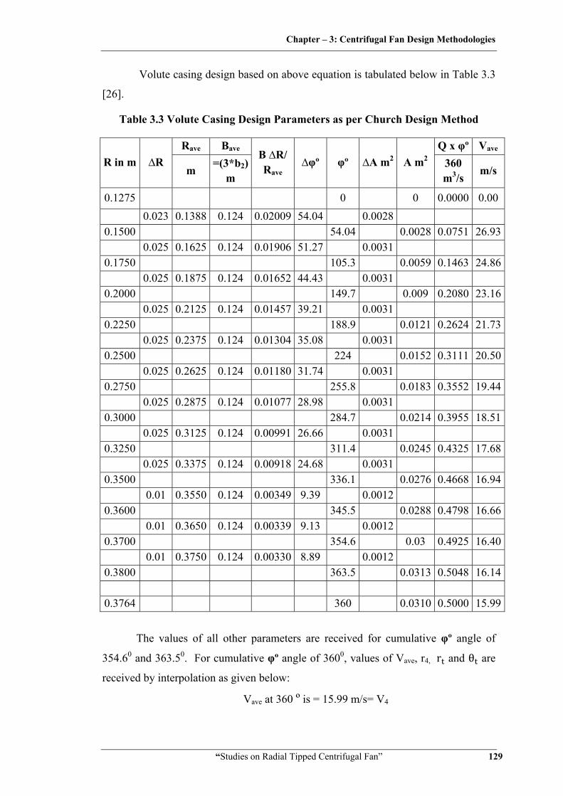
Volute casing design based on above equation is tabulated below in Table 3.3
[26].
Table 3.3 Volute Casing Design Parameters as per Church Design Method
R in m ∆R Rave Bave
B ∆R/ Rave
∆φº φº ∆A m2 A m2 Q x φº Vave
m =(3*b2)
m 360 m3/s
m/s
0.1275 0 0 0.0000 0.00 0.023 0.1388 0.124 0.02009 54.04 0.0028
0.1500 54.04 0.0028 0.0751 26.930.025 0.1625 0.124 0.01906 51.27 0.0031
0.1750 105.3 0.0059 0.1463 24.860.025 0.1875 0.124 0.01652 44.43 0.0031
0.2000 149.7 0.009 0.2080 23.160.025 0.2125 0.124 0.01457 39.21 0.0031
0.2250 188.9 0.0121 0.2624 21.730.025 0.2375 0.124 0.01304 35.08 0.0031
0.2500 224 0.0152 0.3111 20.500.025 0.2625 0.124 0.01180 31.74 0.0031
0.2750 255.8 0.0183 0.3552 19.440.025 0.2875 0.124 0.01077 28.98 0.0031
0.3000 284.7 0.0214 0.3955 18.510.025 0.3125 0.124 0.00991 26.66 0.0031
0.3250 311.4 0.0245 0.4325 17.680.025 0.3375 0.124 0.00918 24.68 0.0031
0.3500 336.1 0.0276 0.4668 16.940.01 0.3550 0.124 0.00349 9.39 0.0012
0.3600 345.5 0.0288 0.4798 16.660.01 0.3650 0.124 0.00339 9.13 0.0012
0.3700 354.6 0.03 0.4925 16.400.01 0.3750 0.124 0.00330 8.89 0.0012
0.3800 363.5 0.0313 0.5048 16.14
0.3764 360 0.0310 0.5000 15.99
The values of all other parameters are received for cumulative φº angle of
354.60 and 363.50. For cumulative φº angle of 3600, values of Vave, r4, r and θ are
received by interpolation as given below:
Vave at 360 º is = 15.99 m/s= V4
Chapter – 3: Centrifugal Fan Design Methodologies
“Studies on Radial Tipped Centrifugal Fan” 130
Radius of volute at angle 360º = r4 =0.376 m = 376 mm
2 376 752
Radius of volute tongue, r 1.075r 1.075 127.5 137 mm
Volute tongue angle, θ 132 log ⁄ / tan 7.7°
3.4.4 Hydraulic, leakage and power losses
3.4.4.1 Leakage loss [26]
0.03
0.03 0.5
0.015 /
3.4.4.2 Suction pressure loss [28]
Friction and turbulence loss in impeller eye,
Where ki is a loss factor probably of the order of 0.5 to 0.8 12 0.65 1.1636 18
122.52
3.4.4.3 Impeller pressure loss [28]
12
At design point of maximum efficiency kii is in order of 0.2 – 0.3 for sheet
metal blades and rather less for aerofoil section. Selecting = 0.25
0.25 1.1636 33.84 17.74
37.82
3.4.4.4 Volute pressure loss [28]
12
kiii is of the order of 0.4 and will vary with deviation from design conditions.
0.412 1.1692 34.14 15.99
71.63

Chapter – 3: Centrifugal Fan Design Methodologies
“Studies on Radial Tipped Centrifugal Fan” 131
3.4.4.5 Disc friction loss [28]
5⁄
5
(Where f is material friction factor in order of 0.005 for mild steel sheet metal)
0.005 1.169237.42
0.12750.1275
5
0.0107
Hence, Power loss due to Disc friction
2
602 2800 0.0107
60 3.14
3.4.5 Efficiencies
3.4.5.1 Hydraulic efficiency
∆∆
981.2
981.2 122.52 37.8 71.63 0.8088
80.88%
3.4.5.2 Volumetric efficiency
0.50.5 0.03 0.5 0.9709 97.1%
3.4.5.3 Total efficiency
0.8088 0.971 0.7647 78.52%
3.4.6 Ideal Shaft power required to run the fan
∆
981.2 122.52 37.8 71.63 0.5 0.0150.7647 3.14 798.8W
,798.8 602 2800
2.7257
Chapter – 3: Centrifugal Fan Design Methodologies
“Studies on Radial Tipped Centrifugal Fan” 132
3.4.7 Shaft diameter [136]
16
16 2.7257 4343 10 0.0117 11.7
3.4.8 Blade profile
Blade Profile is made by tangent arc method [26]. When this method is used,
the impeller is divided into a number of assumed concentric rings, not necessarily
equally spaced between inner and outer radii. The radius Rb of the arc is defining the
blade shape between inner and outer radii.
2 cos cos
12
0.2552
0.1912
0.1912 cos 35.17 0
0.045 46
After obtaining preliminary dimension of fan based on input data further
iterations are made to get optimum design parameters. Next stage of iteration is made
after adding leakage and pressure losses of previous iteration in required design point
discharge and pressure head across the impeller stage as given in input data. This is
done to accommodate possible hydraulic, discharge and power losses at different flow
passages. This process is carried out till there is no marginal dimensional change in
impeller outer diameter and other important parameters. An iterative design procedure
algorithm is shown in Figure 3.1. Summary of designed calculation including few
iterations are given in Table 3.4, while Figure 3.6 to 3.9 gives dimensional drawings
of the fan designed as per Church design.
The Matlab program has been developed for this design calculation and is
given in Annexure A.
Chapter – 3: Centrifugal Fan Design Methodologies
“Studies on Radial Tipped Centrifugal Fan” 133
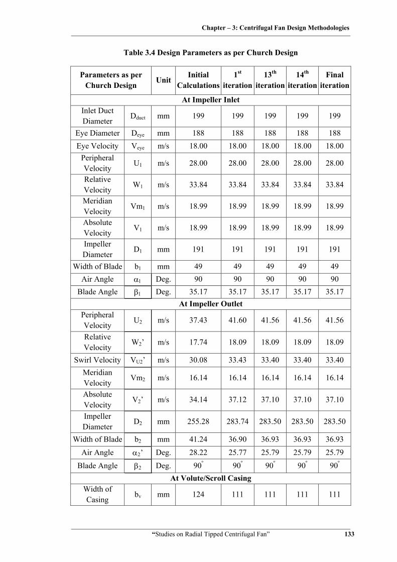
Table 3.4 Design Parameters as per Church Design
Parameters as per Church Design
Unit Initial
Calculations1st
iteration13th
iteration 14th
iteration Final
iteration
At Impeller Inlet Inlet Duct Diameter
Dduct mm 199 199 199 199 199
Eye Diameter Deye mm 188 188 188 188 188 Eye Velocity Veye m/s 18.00 18.00 18.00 18.00 18.00
Peripheral Velocity
U1 m/s 28.00 28.00 28.00 28.00 28.00
Relative Velocity
W1 m/s 33.84 33.84 33.84 33.84 33.84
Meridian Velocity
Vm1 m/s 18.99 18.99 18.99 18.99 18.99
Absolute Velocity
V1 m/s 18.99 18.99 18.99 18.99 18.99
Impeller Diameter
D1 mm 191 191 191 191 191
Width of Blade b1 mm 49 49 49 49 49 Air Angle α1 Deg. 90 90 90 90 90
Blade Angle β1 Deg. 35.17 35.17 35.17 35.17 35.17 At Impeller Outlet
Peripheral Velocity
U2 m/s 37.43 41.60 41.56 41.56 41.56
Relative Velocity
W2’ m/s 17.74 18.09 18.09 18.09 18.09
Swirl Velocity VU2’ m/s 30.08 33.43 33.40 33.40 33.40 Meridian Velocity
Vm2 m/s 16.14 16.14 16.14 16.14 16.14
Absolute Velocity
V2’ m/s 34.14 37.12 37.10 37.10 37.10
Impeller Diameter
D2 mm 255.28 283.74 283.50 283.50 283.50
Width of Blade b2 mm 41.24 36.90 36.93 36.93 36.93
Air Angle α2’ Deg. 28.22 25.77 25.79 25.79 25.79
Blade Angle β2 Deg. 90º 90º 90º 90º 90º At Volute/Scroll Casing
Width of Casing
bv mm 124 111 111 111 111
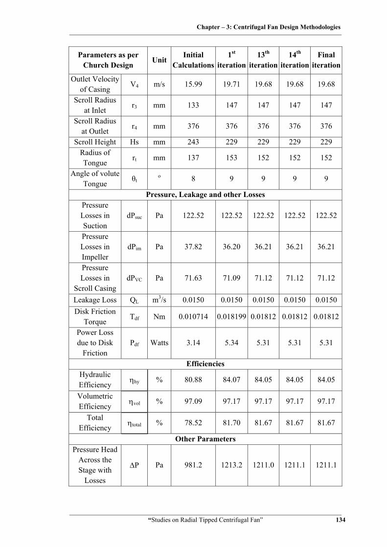
Chapter – 3: Centrifugal Fan Design Methodologies
“Studies on Radial Tipped Centrifugal Fan” 134
Parameters as per Church Design
Unit Initial
Calculations1st
iteration13th
iteration 14th
iteration Final
iteration
Outlet Velocity of Casing
V4 m/s 15.99 19.71 19.68 19.68 19.68
Scroll Radius at Inlet
r3 mm 133 147 147 147 147
Scroll Radius at Outlet
r4 mm 376 376 376 376 376
Scroll Height Hs mm 243 229 229 229 229 Radius of Tongue
rt mm 137 153 152 152 152
Angle of volute Tongue
θt o 8 9 9 9 9
Pressure, Leakage and other Losses Pressure Losses in Suction
dPsuc Pa 122.52 122.52 122.52 122.52 122.52
Pressure Losses in Impeller
dPim Pa 37.82 36.20 36.21 36.21 36.21
Pressure Losses in
Scroll Casing dPVC Pa 71.63 71.09 71.12 71.12 71.12
Leakage Loss QL m3/s 0.0150 0.0150 0.0150 0.0150 0.0150 Disk Friction
Torque Tdf Nm 0.010714 0.018199 0.01812 0.01812 0.01812
Power Loss due to Disk
Friction Pdf Watts 3.14 5.34 5.31 5.31 5.31
Efficiencies Hydraulic Efficiency ηhy % 80.88 84.07 84.05 84.05 84.05
Volumetric Efficiency ηvol % 97.09 97.17 97.17 97.17 97.17
Total Efficiency ηtotal % 78.52 81.70 81.67 81.67 81.67
Other Parameters Pressure Head
Across the Stage with
Losses
ΔP Pa 981.2 1213.2 1211.0 1211.1 1211.1
Chapter – 3: Centrifugal Fan Design Methodologies
“Studies on Radial Tipped Centrifugal Fan” 135
Parameters as per Church Design
Unit Initial
Calculations1st
iteration13th
iteration 14th
iteration Final
iteration
Flow Discharge with
Losses Q m3/s 0.500 0.515 0.515 0.515 0.515
Blade Profile Radius
Rb mm 45.9 70.5 70.3 70.3 70.3
Shaft Diameter Ds mm 11.7 11.6 11.6 11.6 11.6 Power
Required to Run Fan
P Watts 798.8 768.7 769.0 769.0 769.0
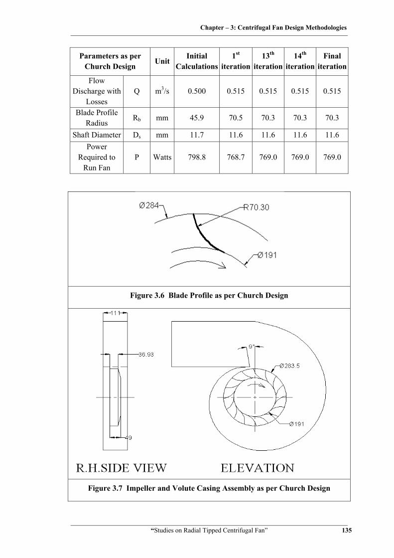
Figure 3.6 Blade Profile as per Church Design
Figure 3.7 Impeller and Volute Casing Assembly as per Church Design
Chapter – 3: Centrifugal Fan Design Methodologies
“Studies on Radial Tipped Centrifugal Fan” 136
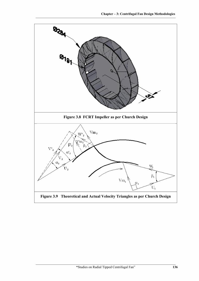
Figure 3.8 FCRT Impeller as per Church Design
Figure 3.9 Theoretical and Actual Velocity Triangles as per Church Design

Chapter – 3: Centrifugal Fan Design Methodologies
“Studies on Radial Tipped Centrifugal Fan” 137
3.5 Design of Radial Tipped Centrifugal Fan as Suggested by William C.
Osborne
[9, 28]
William. C. Osborne has made very good attempt to use simple flow physics
to design fans/blowers. He has used empirical relations for eye velocity, meridian
velocity and casing velocity with respect to impeller tip peripheral velocity. Relative
velocity is considered same for inlet and outlet conditions. This is one of the major
limitations of this design. Suction, impeller, volute pressure losses and leakage losses
are calculated separately. Design procedure and calculations for given input
parameters are as per following.
Fan static pressure gradient, ΔPs = 981.2 Pa.
Fan exit velocity pressure12 ρV Where V is casing outlet velocity
Fan total pressure developed in impeller as per Euler is P ρU Vu
Due to inter blade circulation and considering slip, P ρU Vu
3.5.1 Design of impeller
3.5.1.1 Impeller outlet parameters
Fan static pressure at exit Pse is fan total pressure minus the fan velocity
pressure, 12
reduces to due to blade circulation known as slip in impeller,
sin
sin ,
12
sin
981.212 1.165 1 16
Assuming initially outlet velocity of casing V4 = 0.3U2 [28]. Later it will be
reconsidered as received from scroll casing design.
981.212 1.165 0.3 1.165 0.80375
981.2 0.05242 0.936

Chapter – 3: Centrifugal Fan Design Methodologies
“Studies on Radial Tipped Centrifugal Fan” 138
, 32.87
and sin
27.10 m/s
60
,32.87 60
2800 0.224
224
Taking, Vm1 = Vm2 = 0.2U2 = 6.57 m/s = W2
From, outlet velocity triangle,
6.57 27.10
27.89 /
tan6.5727.1 0.2424
13.64°
3.5.1.2 Impeller inlet parameters
Ideally, the velocity through the impeller inlet/eye should not be more than
Vm1. However, this cannot often be achieved since the inlet diameter becomes too
large, and Veye is generally of the order of twice Vm1 or 0.4U2 [28].
Assuming Veye = 0.4U2 =13.15 m/s
,4
4 0.513.15
0.220 220
To avoid leakage between impeller eye and impeller inlet as being stationary
and rotary geometry respectively, the gap must be minimum.
Taking D1= 1.03 Deye = 1.03 × 220 = 227 mm
Note: Initial calculations are showing impeller inlet diameter D1 large than
impeller outlet diameter D2. This is because of assuming less impeller eye velocity
Chapter – 3: Centrifugal Fan Design Methodologies
“Studies on Radial Tipped Centrifugal Fan” 139
Veye. This will be corrected in further course of iterations by using other design
parameters as received from successive design calculations.
, 60
0.227 280060
33.23 /
,0.5
0.227 6.57 0.107
,0.5
0.224 6.57 0.108
From, inlet velocity triangle,
, tan tan6.57
33.23 11.19°
(Refer Figure 3.13 for inlet and outlet velocity triangles)
, 6.57 33.23 33.87 /
3.5.2 Design of volute casing
As assumed earlier, Casing Outlet Velocity, V4 = 0.3U2
V4 = 0.3 × 32.87= 9.861 m/s
Width of Casing bv for backward curved is 2.5 b2, for forward curved it is 1.25
b2 and for radial tipped blades it is considered 2b2 [28].
∴bv = 2b2
∴bv = 2 × 108
= 216 mm
Casing Outlet Area = 0.5
9.861 0.0507
/ , 2 5224
2 5 117 0.117
And D3 = 0.234 m
Centrifugal fan casing instantaneous radius
1
Where k = 0.0023 for backward curved blades,
k = 0.0020 for forward curved blades and
k = 0.00215 for radial blades
Chapter – 3: Centrifugal Fan Design Methodologies
“Studies on Radial Tipped Centrifugal Fan” 140
1 0.00215
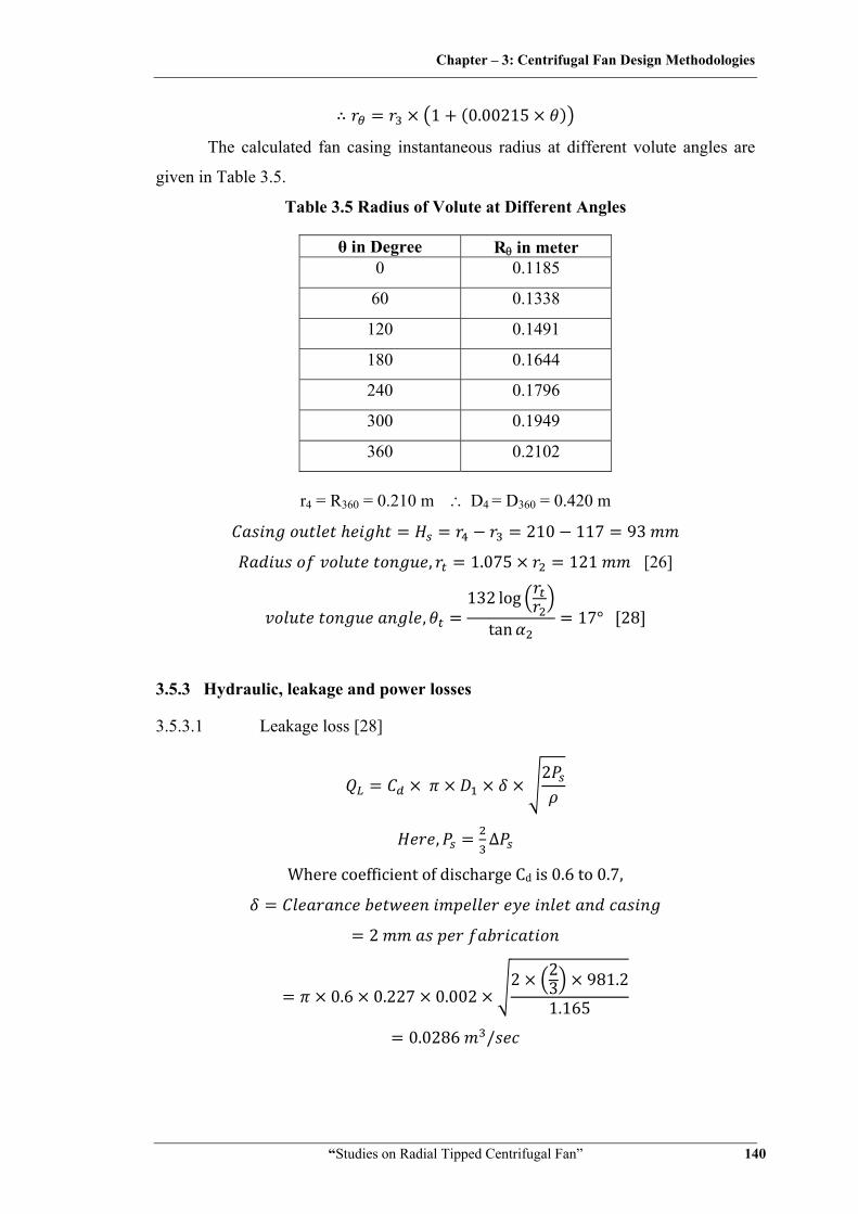
The calculated fan casing instantaneous radius at different volute angles are
given in Table 3.5.
Table 3.5 Radius of Volute at Different Angles
θ in Degree Rθ in meter 0 0.1185
60 0.1338
120 0.1491
180 0.1644
240 0.1796
300 0.1949
360 0.2102
r4 = R360 = 0.210 m ∴ D4 = D360 = 0.420 m
210 117 93
, 1.075 121 [26]
,132 log
tan 17° 28
3.5.3 Hydraulic, leakage and power losses
3.5.3.1 Leakage loss [28]
2
, ∆
Where coefficient of discharge Cd is 0.6 to 0.7,
2
0.6 0.227 0.0022 2
3 981.21.165
0.0286 /
Chapter – 3: Centrifugal Fan Design Methodologies
“Studies on Radial Tipped Centrifugal Fan” 141
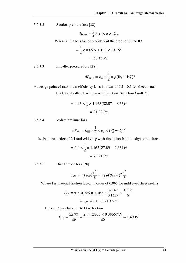
3.5.3.2 Suction pressure loss [28]
Where ki is a loss factor probably of the order of 0.5 to 0.8 12 0.65 1.165 13.15
65.46
3.5.3.3 Impeller pressure loss [28]
12
At design point of maximum efficiency kii is in order of 0.2 – 0.3 for sheet metal
blades and rather less for aerofoil section. Selecting =0.25,
0.2512 1.165 33.87 8.75
91.92
3.5.3.4 Volute pressure loss
12
kiii is of the order of 0.4 and will vary with deviation from design conditions.
0.412 1.165 27.89 9.861
75.71
3.5.3.5 Disc friction loss [28]
5⁄
5
(Where f is material friction factor in order of 0.005 for mild steel sheet metal)
0.005 1.16532.870.112
0.1125
0.0055719
Hence, Power loss due to Disc friction
260
2 2800 0.005571960 1.63

Chapter – 3: Centrifugal Fan Design Methodologies
“Studies on Radial Tipped Centrifugal Fan” 142
3.5.4 Efficiencies
3.5.4.1 Hydraulic efficiency
∆∆
981.2981.2 65.46 91.92 75.71 0.808
80.8%
3.5.4.2 Volumetric efficiency
0.50.5 0.0286 0.9458
94.58%
3.5.4.3 Total efficiency
0.808 0.9458 0.7643
76.43%
3.5.5 Ideal shaft power required to run the fan
∆
981.2 65.46 91.92 75.51 0.5 0.02860.7643 1.63
841.5
,841.5 602 2800
2.871
3.5.6 Shaft diameter [136]
16
16 2.871 4343 10 0.01177 11.77

Chapter – 3: Centrifugal Fan Design Methodologies
“Studies on Radial Tipped Centrifugal Fan” 143
3.5.7 Blade profile
Blade Profile is made by tangent arc method [26]. When this method is used,
the impeller is divided into a number of assumed concentric rings, not necessarily
equally spaced between inner and outer radii. The radius Rb of the arc is defining the
blade shape between inner and outer radii.
2 cos cos
12
0.2242
0.2272
0.2272 cos 11.19 0
0.0012 1.2
Note: During initial calculations, we have assumed V4 = 0.3U2, so we are getting
value of D1 greater than D2 and negative blade profile radius Rb. While iterating
further, V4 is taken as actual received from volute design. Hence there after
design parameters gets corrected.
After obtaining preliminary dimension of fan based on input data further
iterations are made to get optimum design parameters. Next stage of iteration is made
after adding leakage and pressure losses of previous iteration in required design point
discharge and pressure head across the impeller stage as given in input data. This is
done to accommodate possible hydraulic, discharge and power losses at different flow
passages. This process is carried out till there is no marginal dimensional change in
impeller outer diameter and other important parameters. An iterative design procedure
algorithm is shown in Figure 3.1. Summary of designed calculation including few
iterations are given in Table 3.6, while Figure 3.10 to 3.13 gives dimensional
drawings of the fan designed as per Osborne design.
The Matlab program has been developed for this design calculation and is
given in Annexure A.
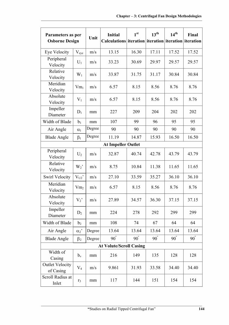
Table 3.6 Design Parameters as per Osborne Design
Parameters as per Osborne Design
Unit Initial
Calculations1st
iteration13th
iteration 14th
iteration Final
iteration
At Impeller Inlet Inlet Duct Diameter
Dduct mm 242 224 218 215 215
Eye Diameter Deye mm 220 203 198 196 196
Chapter – 3: Centrifugal Fan Design Methodologies
“Studies on Radial Tipped Centrifugal Fan” 144
Parameters as per Osborne Design
Unit Initial
Calculations1st
iteration13th
iteration 14th
iteration Final
iteration
Eye Velocity Veye m/s 13.15 16.30 17.11 17.52 17.52 Peripheral Velocity
U1 m/s 33.23 30.69 29.97 29.57 29.57
Relative Velocity
W1 m/s 33.87 31.75 31.17 30.84 30.84
Meridian Velocity
Vm1 m/s 6.57 8.15 8.56 8.76 8.76
Absolute Velocity
V1 m/s 6.57 8.15 8.56 8.76 8.76
Impeller Diameter
D1 mm 227 209 204 202 202
Width of Blade b1 mm 107 99 96 95 95 Air Angle α1 Degree 90 90 90 90 90
Blade Angle β1 Degree 11.19 14.87 15.93 16.50 16.50 At Impeller Outlet
Peripheral Velocity
U2 m/s 32.87 40.74 42.78 43.79 43.79
Relative Velocity
W2’ m/s 8.75 10.84 11.38 11.65 11.65
Swirl Velocity VU2’ m/s 27.10 33.59 35.27 36.10 36.10 Meridian Velocity
Vm2 m/s 6.57 8.15 8.56 8.76 8.76
Absolute Velocity
V2’ m/s 27.89 34.57 36.30 37.15 37.15
Impeller Diameter
D2 mm 224 278 292 299 299
Width of Blade b2 mm 108 74 67 64 64
Air Angle α2’ Degree 13.64 13.64 13.64 13.64 13.64
Blade Angle β2 Degree 90º 90º 90º 90º 90º At Volute/Scroll Casing
Width of Casing
bv mm 216 149 135 128 128
Outlet Velocity of Casing
V4 m/s 9.861 31.93 33.58 34.40 34.40
Scroll Radius at Inlet
r3 mm 117 144 151 154 154

Chapter – 3: Centrifugal Fan Design Methodologies
“Studies on Radial Tipped Centrifugal Fan” 145
Parameters as per Osborne Design
Unit Initial
Calculations1st
iteration13th
iteration 14th
iteration Final
iteration
Scroll Radius at Outlet
r4 mm 210 255 268 274 274
Scroll Height Hs mm 93 111 117 119 119 Radius of Tongue
rt mm 121 149 157 161 161
Angle of volute Tongue
θt Degree 17 17 17 17 17
Pressure, Leakage and other Losses Pressure Losses
in Suction dPsuc Pa 65.46 100.56 110.88 116.18 116.18
Pressure Losses in Impeller
dPim Pa 91.92 63.67 56.99 53.62 53.62
Pressure Losses in Scroll Casing
dPVC Pa 75.71 18.96 4.45 1.77 1.77
Leakage Loss QL m3/s 0.0286 0.0294 0.0281 0.0276 0.0276 Disk Friction
Torque Tdf Nm 0.0055719 0.016299 0.02081 0.02338 0.023382
Power Loss due to Disk Friction
Pdf W 1.63 4.78 6.10 6.86 6.86
Efficiencies Hydraulic Efficiency
hhy % 80.80 86.89 87.11 87.05 87.05
Volumetric Efficiency
hvol % 94.58 94.73 94.95 95.03 95.03
Total Efficiency htotal % 76.43 82.31 82.71 82.72 82.72 Other Parameters
Pressure Head Across the Stage with
Losses
ΔP Pa 981.2 1214.3 1164.4 1152.8 1152.8
Flow Discharge with Losses
Q m3/s 0.500 0.529 0.529 0.528 0.528
Blade Profile Radius
Rb mm -1.2 41.3 55.2 62.7 62.7
Shaft Diameter Ds mm 11.9 11.5 11.5 11.5 11.5 Power Required
to Run Fan P W 841.5 753.7 742.6 742.2 742.2
Chapter – 3: Centrifugal Fan Design Methodologies
“Studies on Radial Tipped Centrifugal Fan” 146
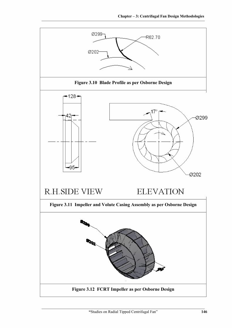
Figure 3.10 Blade Profile as per Osborne Design
Figure 3.11 Impeller and Volute Casing Assembly as per Osborne Design
Figure 3.12 FCRT Impeller as per Osborne Design

Chapter – 3: Centrifugal Fan Design Methodologies
“Studies on Radial Tipped Centrifugal Fan” 147
Figure 3.13 Theoretical and Actual Velocity Triangles as per Osborne Design
3.6 Comparative Assessment of Explicit Design Methodologies
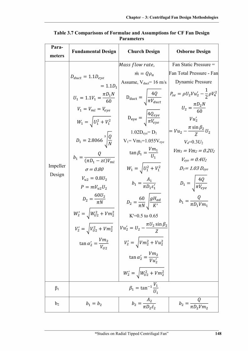
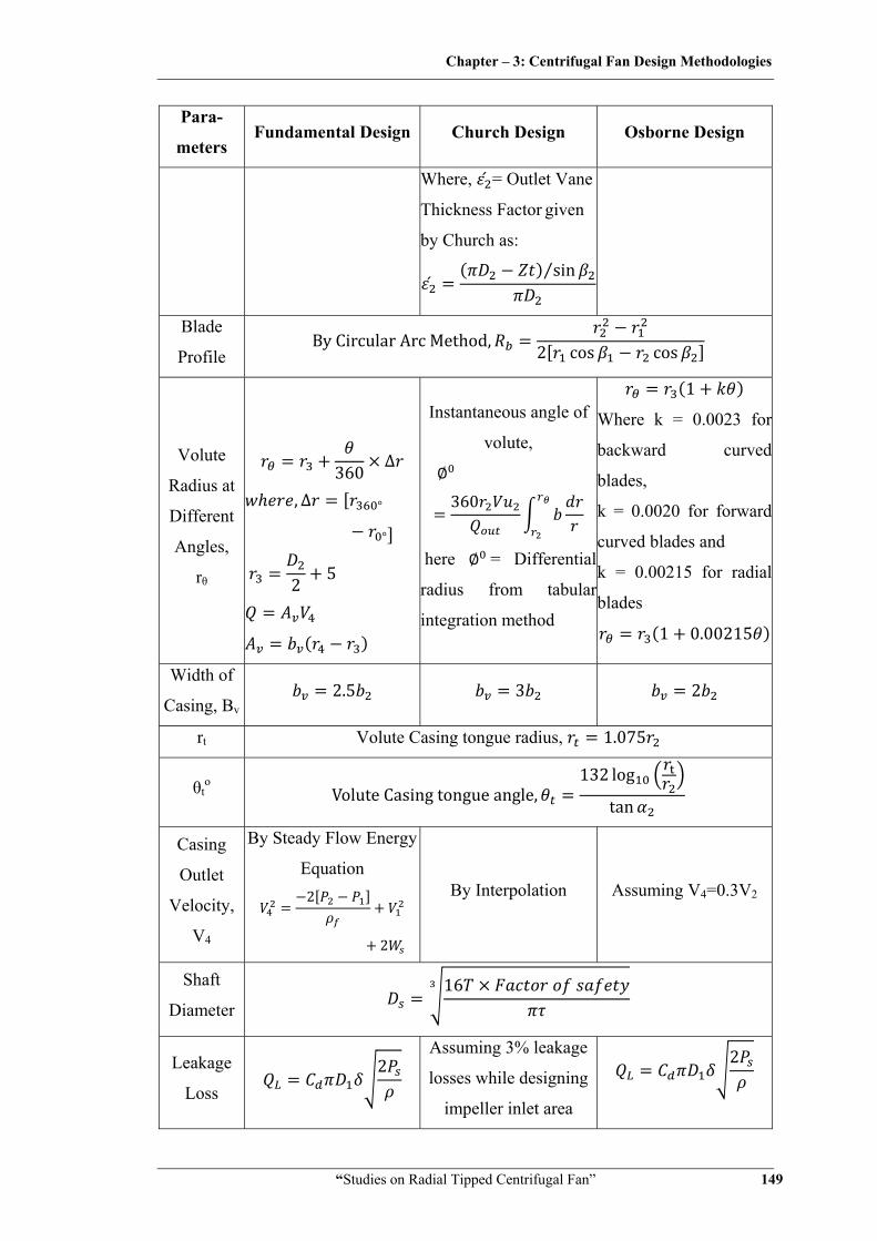
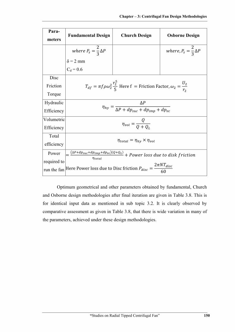
Table 3.7 shows comparison of various formulae and assumptions used in case
of each design methodology.
Chapter – 3: Centrifugal Fan Design Methodologies
“Studies on Radial Tipped Centrifugal Fan” 148
Table 3.7 Comparisons of Formulae and Assumptions for CF Fan Design Parameters
Para-
meters Fundamental Design Church Design Osborne Design
Impeller
Design
1.1
1.1
1.1 60
2.8066
σ 0.80 0.8
60
tan
,
Assume, Vduct= 16 m/s
D4
D4
1.02Deye= D1
V1= Vm1=1.055Veye
tan
60
K'=0.5 to 0.65
sin
tan
Fan Static Pressure =
Fan Total Pressure - Fan
Dynamic Pressure 12
60
sin
V4=0.3U2
Vm1 Vm2 0.2U2 Veye 0.4U2
D1 1.03 Deye
4
β1 tan
b2
Chapter – 3: Centrifugal Fan Design Methodologies
“Studies on Radial Tipped Centrifugal Fan” 149
Para-
meters Fundamental Design Church Design Osborne Design
Where, = Outlet Vane
Thickness Factor given
by Church as:
sin⁄
Blade
Profile By Circular Arc Method, 2 cos cos
Volute
Radius at
Different
Angles,
rθ
360 ∆
, ∆ °
°
2 5
Instantaneous angle of
volute,
360
here = Differential
radius from tabular
integration method
1
Where k = 0.0023 for
backward curved
blades,
k = 0.0020 for forward
curved blades and
k = 0.00215 for radial
blades
1 0.00215
Width of
Casing, Bv 2.5 3 2
rt Volute Casing tongue radius, 1.075
θto
Volute Casing tongue angle,132 log
tan
Casing
Outlet
Velocity,
V4
By Steady Flow Energy
Equation 2
2
By Interpolation Assuming V4=0.3V2
Shaft
Diameter 16
Leakage
Loss 2
Assuming 3% leakage
losses while designing
impeller inlet area
2
Chapter – 3: Centrifugal Fan Design Methodologies
“Studies on Radial Tipped Centrifugal Fan” 150
Para-
meters Fundamental Design Church Design Osborne Design
23 ∆
δ = 2 mm
Cd = 0.6
,23 ∆
Disc
Friction
Torque 5 Here f Friction Factor,
Hydraulic
Efficiency
∆∆
Volumetric
Efficiency
Total
efficiency
Power
required to
run the fan
∆
Here Power loss due to Disc friction2
60
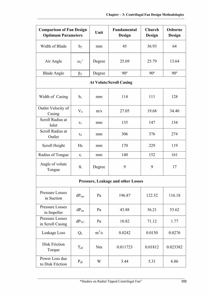
Optimum geometrical and other parameters obtained by fundamental, Church
and Osborne design methodologies after final iteration are given in Table 3.8. This is
for identical input data as mentioned in sub topic 3.2. It is clearly observed by
comparative assessment as given in Table 3.8, that there is wide variation in many of
the parameters, achieved under these design methodologies.

Chapter – 3: Centrifugal Fan Design Methodologies
“Studies on Radial Tipped Centrifugal Fan” 151
Table 3.8 Optimum Design Parameters as per Fundamental, Church and Osborne Design
Comparison of Fan Design Optimum Parameters
Unit Fundamental
Design Church Design
Osborne Design
At Impeller Inlet
Inlet Duct Diameter
Dduct mm 188 199 215
Eye Diameter Deye mm 171 188 196
Eye Velocity Veye m/s 22.80 18.00 17.52
Peripheral Velocity
U1 m/s 25.08 28.00 29.57
Relative Velocity W1 m/s 33.90 33.84 30.84
Meridian Velocity
Vm1 m/s 22.80 18.99 8.76
Absolute Velocity V1 m/s 22.80 18.99 8.76
Impeller Diameter D1 mm 171 191 202
Width of Blade b1 mm 45 49 95
Air Angle α1 Degree 90 90 90
Blade Angle β1 Degree 42.35 35.17 16.50
At Impeller Outlet
Peripheral Velocity
U2 m/s 38.14 41.56 43.79
Relative Velocity W2’ m/s 16.54 18.09 11.65
Swirl Velocity VU2’ m/s 30.52 33.40 36.10
Meridian Velocity
Vm2 m/s 14.68 16.14 8.76
Absolute Velocity V2’ m/s 33.86 37.10 37.15
Impeller Diameter D2 mm 260 283.50 299
Chapter – 3: Centrifugal Fan Design Methodologies
“Studies on Radial Tipped Centrifugal Fan” 152
Comparison of Fan Design Optimum Parameters
Unit Fundamental
Design Church Design
Osborne Design
Width of Blade b2 mm 45 36.93 64
Air Angle α2’ Degree 25.69 25.79 13.64
Blade Angle β2 Degree 90º 90º 90º
At Volute/Scroll Casing
Width of Casing bv mm 114 111 128
Outlet Velocity of Casing
V4 m/s 27.05 19.68 34.40
Scroll Radius at Inlet
r3 mm 135 147 154
Scroll Radius at Outlet
r4 mm 306 376 274
Scroll Height Hs mm 170 229 119
Radius of Tongue rt mm 140 152 161
Angle of volute Tongue
θt Degree 9 9 17
Pressure, Leakage and other Losses
Pressure Losses in Suction
dPsuc Pa 196.87 122.52 116.18
Pressure Losses in Impeller
dPim Pa 43.88 36.21 53.62
Pressure Losses in Scroll Casing
dPVC Pa 10.82 71.12 1.77
Leakage Loss QL m3/s 0.0242 0.0150 0.0276
Disk Friction Torque
Tdf Nm 0.011723 0.01812 0.023382
Power Loss due to Disk Friction
Pdf W 3.44 5.31 6.86

Chapter – 3: Centrifugal Fan Design Methodologies
“Studies on Radial Tipped Centrifugal Fan” 153
Comparison of Fan Design Optimum Parameters
Unit Fundamental
Design Church Design
Osborne Design
Efficiencies
Hydraulic Efficiency
hhy % 83.05 84.05 87.05
Volumetric Efficiency
hvol % 95.58 97.17 95.03
Total Efficiency htotal % 79.38 81.67 82.72 Other Parameters
Pressure Head Across the Stage
with Losses ΔP Pa 1232.754 1211.1 1152.8
Flow Discharge with Losses
Q m3/s 0.5242 0.5150 0.5276
Blade Profile Radius
Rb mm 75.9 70.3 62.7
Shaft Diameter ds mm 11.8 11.6 11.5 Power Required
to Run Fan P W 817.5 769.0 742.2
Radial tipped centrifugal fans are fabricated for each design methodology as
per optimum parameters given in Table 3.8. These fans are tested as per test standard
IS: 4894-1987, Indian Standard Specification for Centrifugal Fans, 1994 [17]. Precise
and calibrated instruments are used to get accurate results. Observations are made for
static pressure distribution along the flow path and for variable flow rate at outlet,
accompanied with other associated parameters. This was done at designed and off
design rotational speeds. Experimental set up, procedure and results are discussed in
detail in subsequent chapters.
The performance of fans fabricated as per individual and explicit design
methodologies suggested by Church, Osborne and retrieved from fundamental
principles of fluid flow having minimum assumptions, is critically evaluated. Based
on experimental results obtained, it is observed that there exists a wide performance
difference amongst fans under study. It concludes that each design method, as an
individual, is not performing as marked. It has also revealed that there is a need to
develop unified design methodology.
Chapter – 3: Centrifugal Fan Design Methodologies
“Studies on Radial Tipped Centrifugal Fan” 154
3.7 Unified Design Methodology
Successful outcomes of fundamental design [9, 10, 14, 28], Church design [9,
26, 28] and Osborne design [9, 28] are incorporated together and a new design
methodology for radial tipped centrifugal fan is developed. It is to be noted here that
the unified design is derived, based on non- dimensional parameters with inclusion of
compressibility effect which makes it quite generalized for application to wide range
of radial tipped centrifugal machines. This is named as unified design methodology
for radial tipped centrifugal fan. Input parameters are identical as considered in
previous designs. This work is presented in three sections.
Non- dimensional parameters
Impeller design
Scroll casing design
3.7.1 Non- dimensional parameters
[14, 28, 56]
The turbo machine designer is often faced with the basic problem of deciding
what type of turbomachine will be the best choice for a given duty. Usually the
designer is provided with some preliminary design data such as the head H, the
volume flow rate Q and the rotational speed N when a pump, fan or compressor
design is under consideration. For the design, comparison, and critical assessment of
all fans, dimensionless coefficients have been used [14, 56]. These coefficients must
be dimensionless so that the numerical values can be independent of the actual
increases in pressure, mass flow, and other physical properties.
Important non- dimensional coefficients used in literature are specific speed,
pressure coefficient, volume coefficient, power coefficient, speed coefficient,
diameter coefficient and noise coefficient. These parameters are briefly explained
below.
• Specific speed Ns
A non-dimensional parameter called the specific speed, Ns, referred to and
conceptualized as the shape number, is often used to facilitate the choice of the most
appropriate machine. This parameter is derived from the non-dimensional groups in
such a way that the characteristic diameter D of the turbo machine is eliminated. The
value of Ns gives the designer a guide to the type of machine that will provide the
normal requirement of high efficiency at the design condition.

Chapter – 3: Centrifugal Fan Design Methodologies
“Studies on Radial Tipped Centrifugal Fan” 155
Specific speed is a criterion at which a fan of unspecified diameter would run
to give unit volume flow and pressure. This applies to all fans in a homologous series.
This is derived from the fan laws by elimination of the diameter term, thus:
/
• Pressure coefficient ψ
The fan impeller has a typical outside diameter d2, and a typical peripheral
velocity u2. As a possible basis of comparison for the pressure produced by the
impeller, the dynamic pressure of the peripheral velocity ρu22/2 is considered. This
coefficient affects the fan noise and has a dependent relationship with the other
coefficients. For example, if designer wants to design a minimal noise-generation fan,
then the maximum value of pressure coefficient must be selected. Thus the pressure
coefficient Ψ can be defined as the ratio of the pressure produced by the impeller and
the pressure of the peripheral velocity. Δ
2
• Volume coefficient Φ
Volume coefficient Φ is a ratio of actual volume flow to that of theoretical
one. The volume flow Q per second requires a similar basis of comparison. So the
circular area of the impeller πd22/4 can be employed, through which the flowing
medium passes with a velocity U2. Thus, the volume flow can be expressed as Q=
(U2πd22)/4. Naturally, this volume differs from the actual volume: therefore the
volume coefficient Φ can be obtained from the difference between the actual volume
and the theoretical volume. This coefficient will affect the capacity and the noise of
the fan. The maximum value of the volume coefficient will cause the maximum
capacity, while the minimum value will cause the minimum noise. The volume
coefficient is expressed as follows:
Φ = Q
((U2πD22)/4)
D2
(U2πD22)/4)
4
Chapter – 3: Centrifugal Fan Design Methodologies
“Studies on Radial Tipped Centrifugal Fan” 156
• Power coefficient λ
Power coefficient is also known as output coefficient or coefficient of
performance. This is associated with driving shaft power input to head and volume
flow generated by the impeller. This is expressed mathematically as follows:
λ
• Speed coefficient σ and diameter coefficient δ
In practice, pressure and volume coefficients have been found inadequate for
numerical evaluation of the important characteristics of the centrifugal impeller. For
any given volume flow Q and a given pressure increase Δp can be produced by
various fans which are widely different in their dimensions. The price of a fan is often
dependent upon its size, and the importance of this from the point of view of the
designer cannot be over-emphasized. Moreover, the designer often requires a
specified speed, so coefficients relating to the dimensions and speed of a fan are
necessary.
The diameter coefficient δ indicates the number of times greater the diameter
of an impeller is, in relation to the diameter of a model impeller with Ψ = 1 and Φ = 1.
These coefficients are related to head, flow rate, outlet diameter, and motor speed.
Therefore, if the designer selects those values, the speed and diameter coefficient can
be calculated. The coefficients are expressed as follows:
Speed coefficient, σ nQ
2gH √π1
28.5 QΔPρ N
Speed coefficient, σ 0.379 nQH
0.379N /
60 /
Diameter coefficient, δ 1.865 dHQ
Also, these coefficients are dependent on each other and related to the pressure
and volume coefficients. Therefore, these coefficients can be expressed in the form of
pressure and volume coefficients.
, 1σ δ
, 1σδ

Chapter – 3: Centrifugal Fan Design Methodologies
“Studies on Radial Tipped Centrifugal Fan” 157
• Noise coefficient
Nowadays, investigations of fan noise are extremely important, due to
advances in air-conditioning and ventilation techniques. Fan noise can be expressed as
a function of the volume coefficient Φ and the pressure coefficient ψ. Variation from
the optimum volume coefficient and pressure coefficient either due to an increase or
decrease in volume and pressure, results in an increase or decrease in sound level.
Therefore, to design a minimum-noise fan, the designer should select the minimum
value of the volume coefficient and the maximum value of the pressure coefficient.
The noise coefficient τ can be expressed as follows:
τΦψ
Referring to input design data for radial tipped centrifugal fan given in
section 3.2, unified design procedure using non- dimensional coefficients is as per
following:
,
260
2 280060 0.5
9.81 85.59
1.3292
, 0.379 /
60 / 0.4443
Cordier has given the relation between σ1and δ in graphical form as shown in
Figure 3.14.
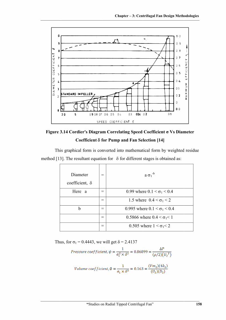
Figure 3
Thi
method [13
Thu
3.14 Cordie
Coe
s graphical
3]. The resu
Diame
coefficie
Here
b
us, for σ1 = 0
“Studies o
er's Diagra
efficient δ f
form is con
ltant equatio
eter
ent, δ
=
a =
=
=
=
=
0.4443, we
Chap
on Radial Tipp
m Correlat
for Pump a
nverted into
on for δ fo
=
=
=
=
=
=
will get δ =
pter – 3: Cent
ped Centrifuga
ting Speed
and Fan Sel
o mathemat
or different
0.99 wher
1.5 wher
0.995 whe
0.5866 w
0.505 w
= 2.4137
trifugal Fan D
al Fan”
Coefficien
lection [14]
tical form b
stages is ob
a σ1-b
re 0.1 < σ1
re 0.4 < σ1
ere 0.1 < σ1
where 0.4 < σ
where 1 < σ1
Design Meth
t σ Vs Diam
]
by weighted
btained as:
< 0.4
< 2
< 0.4
σ1< 1
1< 2
odologies
158
meter
d residue
Chapter – 3: Centrifugal Fan Design Methodologies
“Studies on Radial Tipped Centrifugal Fan” 159
3.7.2 Effect of compressibility on design
[26]
If flow is steady, mass flow remains constant but density will change at
different flow sections due to change in temperature and pressure. Hence volume flow
Q will change. This is compressibility effect. From characteristic equation of gas:
. ,1.01325 10
287 303 1.1652 /
, 0.58259 /
,1.011286 10
287 303 1.1629 /
, 0.50098 /
,1.021098 10
287 303 1.1742 /
∆ 981.2
∆
2 1.1686
, 85.5928
3.7.3 Design of impeller
3.7.3.1 Impeller outlet parameters
Here,
,1.021098 10
287 303 1.1742 /
∆ 981.2
And,
,1
0.86899∆
2⁄
44.03 /
60
0.300
Now,

Chapter – 3: Centrifugal Fan Design Methodologies
“Studies on Radial Tipped Centrifugal Fan” 160
,1
0.1634
Assuming Vm1 = Vm2 = 0.2U2 = 8.81 m/s = [28]
0.061 61
Parallel shroud plates are taken for impeller, hence impeller width at inlet and
outlet will be equal. . This parameter will be verified at the end of impeller
stage calculations and major dimension will be considered.
Now, due to blade passage circulation effect (slip):
sin 3.1416 0.80375 35.38 /
From velocity triangle,
, 36.46 /
tan
13.98°
8.65 /
Now, outlet relative velocity with slip, 12.34 /
3.7.3.2 Impeller inlet parameters
Assuming Veye = 0.4U2 = 0.4 × 44.03 = 17.61 m/s [28]
,4
4 0.517.54
0.190 190
Taking 1.1 D1= Deye
= 191/1.1 = 173 mm
, 60
0.174 280060
25.34 /
8.81 /

Chapter – 3: Centrifugal Fan Design Methodologies
“Studies on Radial Tipped Centrifugal Fan” 161
25.5 8.77 26.82 /s
tan8.7725.5
19.16°
(Refer Figure 3.18 for inlet and outlet velocity triangles)
Virtual head developed by impeller, 1
2 95.01
Where
2
2
It may be assumed that, owing to the circulatory flow, friction and turbulence
in the impeller, 15 percent of this virtual head is lost.
Hence effective head 0.85 0.85 95.01 80.78
Impeller outlet pressure is based upon effective head so,
. 10.286 0.286 9.81 80.78
287 302.79 0.00261
Where ∈Pimp= Pressure ratio between impeller eye and impeller outlet base
upon effective head.
1.00916
Impeller outlet pressure, 1.00916 101128.6
102054.9
The friction and turbulence losses will be transformed into heat which raises
the temperature of air. The impeller outlet temperature may be based upon the
adiabatic head in the impeller neglecting losses.
. 10.286 0.286 9.81 85.59
287 302.83 0.00276
The outlet temperature, . 303.61
Impeller outlet density,102046.9
287 303.61 1.1711 kg/m
Impeller exit volume flow,0.58251.1711 0.4974 ⁄
Chapter – 3: Centrifugal Fan Design Methodologies
“Studies on Radial Tipped Centrifugal Fan” 162
Impeller outlet area, 0.49748.81 0.0565
Taking optimized numbers of blades, Z = 16 and blade thickness t = 2 mm,
, 0.0619
62
Considering parallel shrouded impeller, so
62 mm
It is seen that impeller width received from dimensionless coefficient and
other one based on impeller exit area have very marginal difference. Here major
dimension is selected.
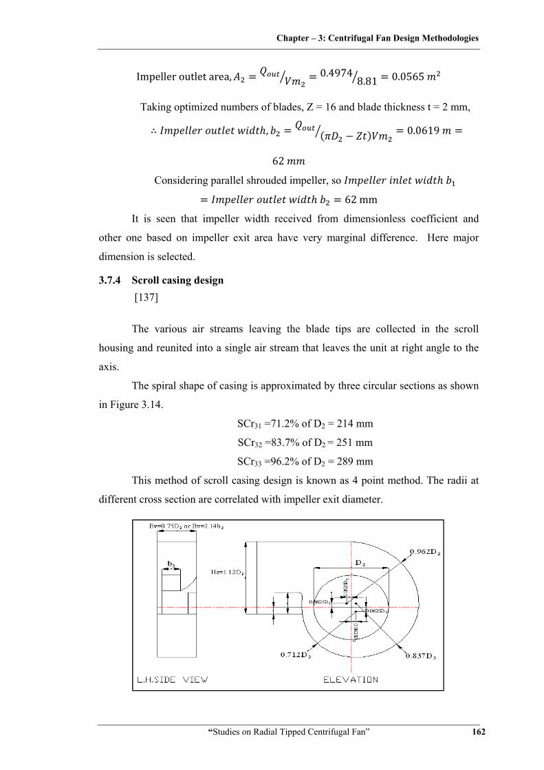
3.7.4 Scroll casing design [137]
The various air streams leaving the blade tips are collected in the scroll
housing and reunited into a single air stream that leaves the unit at right angle to the
axis.
The spiral shape of casing is approximated by three circular sections as shown
in Figure 3.14.
SCr31 =71.2% of D2 = 214 mm
SCr32 =83.7% of D2 = 251 mm
SCr33 =96.2% of D2 = 289 mm
This method of scroll casing design is known as 4 point method. The radii at
different cross section are correlated with impeller exit diameter.

Chapter – 3: Centrifugal Fan Design Methodologies
“Studies on Radial Tipped Centrifugal Fan” 163
Figure 3.15 Scroll Casing Design by 4 Point Method [137]
Centre of these three are located off the centre lines by interval of 6.25% of
wheel dia. = 18.7 mm
Width of housing is 75% of D2 = 225 mm
Height of housing outlet is 112% of D2= 336 mm
, 1.075 161.25 [26]
,132 log
tan 16.65° 26
At the housing outlet, two piece of cut off is used which is placed only on the
inlet side of housing which is called as recirculation shield. The purpose of
recirculation shield is to minimize the recirculation of the bypassing air (which of
course, is a loss in air volume and efficiency) without producing excessive noise due
to a small cutoff clearance. In other words, the 5 to 10% cutoff clearance is a
compromise between prevention of recirculation and quiet operation. The
recirculation shield protrudes into housing outlet by 30 to 35% of outlet height. Here
35% of D2 exit shield is considered. We know that,
Impeller exit volume flow, 0.4974 ⁄
Same volume flow must leave volute casing at exit. Exit volute area
1 0.35 0.65 0.336 0.225 0.049 0.49740.049 10.11 /
3.7.5 Hydraulic, leakage and power losses
3.7.5.1 Leakage loss [26]
0.03 0.03 0.5 0.015 /
3.7.5.2 Suction pressure loss [28]
Friction and turbulence loss in impeller eye
where ki is a loss factor probably of the order of 0.5 to
0.8 12 0.65 1.1629 17.61
117.28

Chapter – 3: Centrifugal Fan Design Methodologies
“Studies on Radial Tipped Centrifugal Fan” 164
3.7.5.3 Impeller pressure loss [28]
12
At design point of maximum efficiency kii is in order of 0.2 – 0.3 for sheet metal
blades and rather less for aerofoil section. Selecting kii = 0.25
0.2512 1.1686 26.83 12.34
30.62
3.7.5.4 Volute pressure loss [28]
12
kiii is of the order of 0.4 and will vary with deviation from design conditions.
0.412 1.1742 36.46 10.11
162.69
3.7.5.5 Disc friction loss [28]
5⁄
5
(Where f is material friction factor in order of 0.005 for mild steel sheet metal)
0.005 1.168644.030.150
0.1505
0.02414
Hence, Power loss due to Disc friction 2
602 2800 0.02414
60 7.08
3.7.6 Efficiencies
3.7.6.1 Hydraulic efficiency
∆∆
981.2981.2 117.28 30.62 162.69 0.7596
75.96 76%

Chapter – 3: Centrifugal Fan Design Methodologies
“Studies on Radial Tipped Centrifugal Fan” 165
3.7.6.2 Volumetric efficiency
0.50.5 0.015 0.971 97.1%
3.7.6.3 Total efficiency
0.7596 0.971 0.7375 73.75%
3.7.7 Ideal shaft power required to run the fan
∆
981.2 117.28 30.62 162.69 0.5 0.0150.7375 7.08
909.18
,909.18 602 2800
3.102
3.7.8 Shaft diameter [136]
16
16 3.102 4343 10 0.01223 12.26
3.7.9 Blade profile
Blade Profile is made by tangent arc method [26]. When this method is used,
the impeller is divided into a number of assumed concentric rings, not necessarily
equally spaced between inner and outer radii. The radius Rb of the arc is defining the
blade shape between inner and outer radii.
2 cos cos
12
0.3002
0.1732
0.1732 cos 19.16 0
0.09235 92.35
After obtaining preliminary dimension of fan based on input data further
iterations are made to get optimum design parameters. Next stage of iteration is made
Chapter – 3: Centrifugal Fan Design Methodologies
“Studies on Radial Tipped Centrifugal Fan” 166
after adding leakage and pressure losses of previous iteration in required design point
discharge and pressure head across the impeller stage as given in input data. This is
done to accommodate possible hydraulic, discharge and power losses at different flow
passages. This process is carried out till there is no marginal dimensional change in
impeller outer diameter and other important parameters. An iterative design procedure
algorithm is shown in Figure 3.1. Summary of designed calculation including few
iterations are given in Table 3.9, while Figure 3.16 to 3.19 gives dimensional
drawings of the fan designed as per Unified Design.
The Matlab program has been developed for this design calculation and is
given in Annexure A.
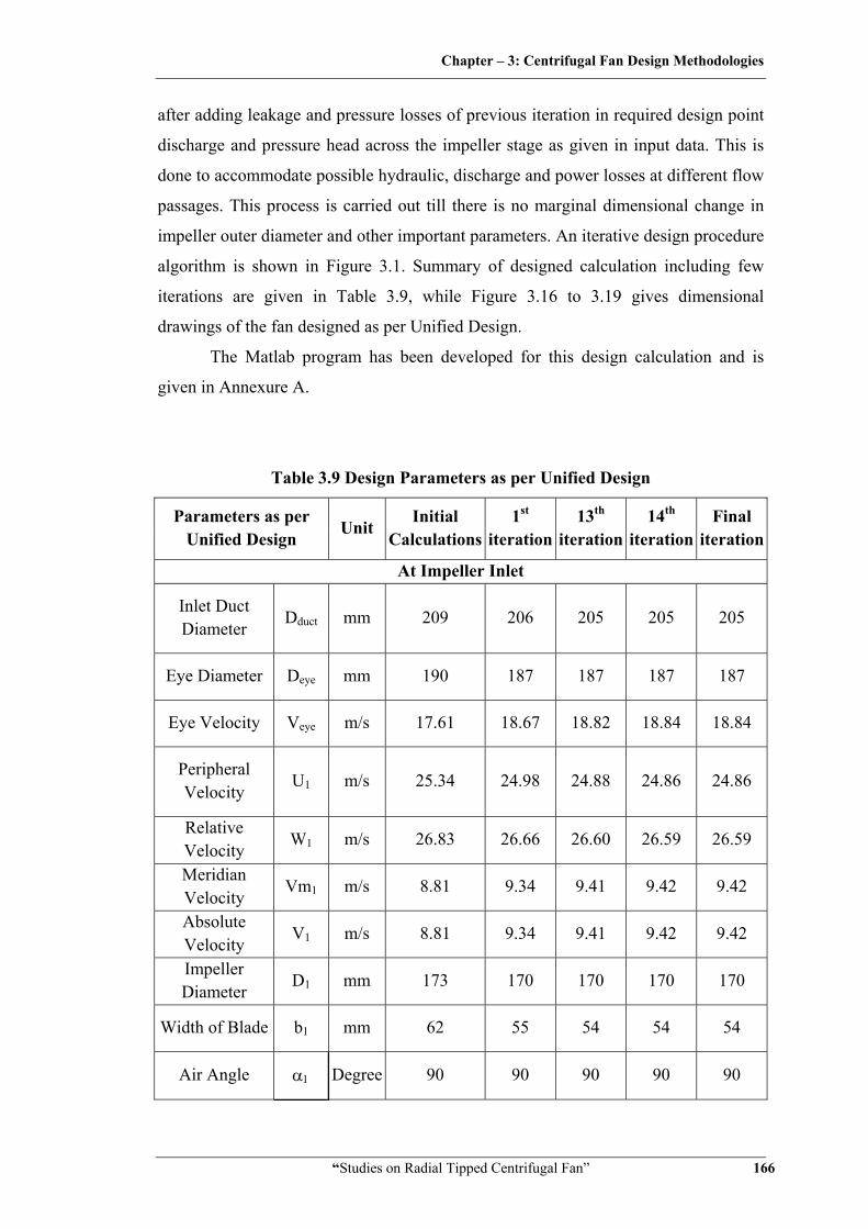
Table 3.9 Design Parameters as per Unified Design
Parameters as per Unified Design
Unit Initial
Calculations1st
iteration13th
iteration 14th
iteration Final
iteration
At Impeller Inlet
Inlet Duct Diameter
Dduct mm 209 206 205 205 205
Eye Diameter Deye mm 190 187 187 187 187
Eye Velocity Veye m/s 17.61 18.67 18.82 18.84 18.84
Peripheral Velocity
U1 m/s 25.34 24.98 24.88 24.86 24.86
Relative Velocity
W1 m/s 26.83 26.66 26.60 26.59 26.59
Meridian Velocity
Vm1 m/s 8.81 9.34 9.41 9.42 9.42
Absolute Velocity
V1 m/s 8.81 9.34 9.41 9.42 9.42
Impeller Diameter
D1 mm 173 170 170 170 170
Width of Blade b1 mm 62 55 54 54 54
Air Angle α1 Degree 90 90 90 90 90
Chapter – 3: Centrifugal Fan Design Methodologies
“Studies on Radial Tipped Centrifugal Fan” 167
Parameters as per Unified Design
Unit Initial
Calculations1st
iteration13th
iteration 14th
iteration Final
iteration
Blade Angle β1 Degree 19.16 20.49 20.72 20.75 20.75
At Impeller Outlet
Peripheral Velocity
U2 m/s 44.03 46.68 47.04 47.10 47.10
Relative Velocity
W2’ m/s 12.34 13.08 13.19 13.20 13.20
Swirl Velocity VU2’ m/s 35.38 37.51 37.81 37.86 37.86
Meridian Velocity
Vm2 m/s 8.81 9.34 9.41 9.42 9.42
Absolute Velocity
V2’ m/s 36.46 38.66 38.96 39.01 39.01
Impeller Diameter
D2 mm 300 318 321 321 321
Width of Blade b2 mm 62 55 54 54 54
Air Angle α2’ Deg. 13.98 13.98 13.98 13.98 13.98
Blade Angle β2 Deg. 90º 90º 90º 90º 90º
At Volute/Scroll Casing Width of Casing
bv mm 225 239 241 241 241
Outlet Velocity of Casing
V4 m/s 10.10 8.98 8.84 8.82 8.82
Scroll Radius at Inlet
r3 mm 214 227 228 229 229
Scroll Radius at Outlet
r4 mm 289 306 309 309 309
Scroll Height Hs mm 336 357 359 360 360
Radius of Tongue
rt mm 161.25 171 172.5 172.5 172.5

Chapter – 3: Centrifugal Fan Design Methodologies
“Studies on Radial Tipped Centrifugal Fan” 168
Parameters as per Unified Design
Unit Initial
Calculations1st
iteration13th
iteration 14th
iteration Final
iteration
Angle of volute Tongue
θt Degree 16.65 16.66 16.66 16.66 16.66
Pressure, Leakage and other Losses
Pressure Losses in Suction
dPsuc Pa 117.28 131.82 133.91 134.25 134.25
Pressure Losses in Impeller
dPim Pa 30.62 26.93 26.26 26.16 26.16
Pressure Losses in Scroll Casing
dPVC Pa 162.69 206.35 212.62 213.63 213.63
Leakage Loss QL m3/s 0.0150 0.0150 0.0150 0.0150 0.0150
Disk Friction Torque
Tdf Nm 0.02414 0.03236 0.03366 0.03387 0.03387
Power Loss due to Disk Friction
Pdf W 7.08 9.49 9.87 9.93 9.93
Efficiencies
Hydraulic Efficiency
hhy % 75.96 77.96 78.31 78.37 78.37
Volumetric Efficiency
hvol % 97.09 97.09 97.09 97.09 97.09
Total Efficiency
htotal % 73.75 75.70 76.04 76.09 76.09
Other Parameters Pressure Head
Across the Stage with
Losses
ΔP Pa 1291.8 1291.8 1346.3 1355.2 1355.2
Flow Discharge with Losses
Q m3/s 0.5150 0.5150 0.5150 0.5150 0.5150
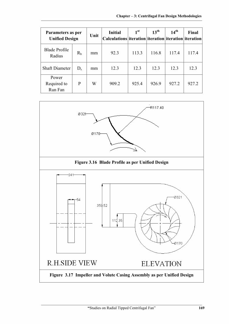
Chapter – 3: Centrifugal Fan Design Methodologies
“Studies on Radial Tipped Centrifugal Fan” 169
Parameters as per Unified Design
Unit Initial
Calculations1st
iteration13th
iteration 14th
iteration Final
iteration
Blade Profile Radius
Rb mm 92.3 113.3 116.8 117.4 117.4
Shaft Diameter Ds mm 12.3 12.3 12.3 12.3 12.3
Power Required to
Run Fan P W 909.2 925.4 926.9 927.2 927.2
Figure 3.16 Blade Profile as per Unified Design
Figure 3.17 Impeller and Volute Casing Assembly as per Unified Design

Chapter – 3: Centrifugal Fan Design Methodologies
“Studies on Radial Tipped Centrifugal Fan” 170
Figure 3.18 FCRT Impeller as per Unified Design
Figure 3.19 Theoretical and Actual Velocity Triangles as per Unified Design

Chapter – 3: Centrifugal Fan Design Methodologies
“Studies on Radial Tipped Centrifugal Fan” 171
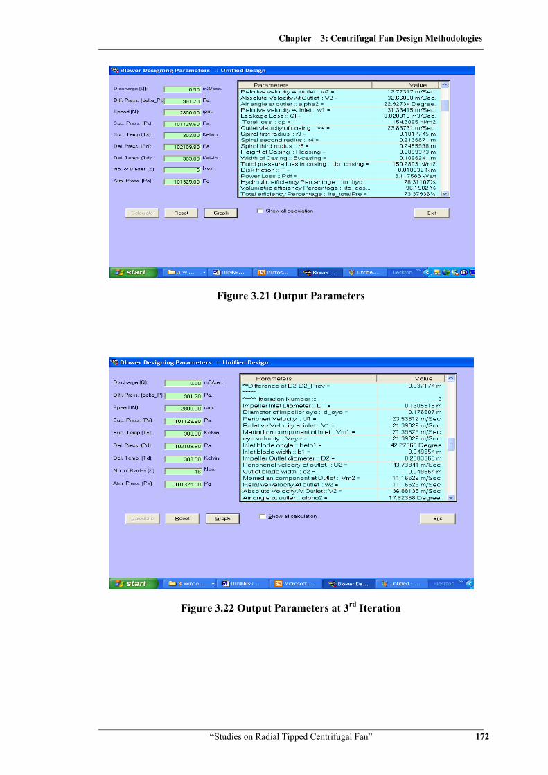
3.8 Snapshots of Visual Basic Computer Program for Unified Design
Making of design calculations and iterations is cumbersome process. Number
of variables and coefficients should be taken into account while designing. It needs
number of iterations before reaching to optimum parameters. In present era of
computerization, it can be made faster by writing sequential program in various
softwares like Matlab, Visual Basic and Turbo C. Microsoft Visual Basic 6.0 is the
latest and the greatest incarnation of old Basic Language. It gives a complete window
base application development system in one package. Visual Basic writes, edits and
tests in single window application. VB includes tools that can be used to write and
compile help files, active X controls and even internet applications. When we write a
statement in Visual Basic language, the statement never has multiple meaning within
the same context.
User-friendly software in Visual basic is prepared for designing radial tipped
centrifugal fan based on proposed unified design methodology. Few frames from this
software are presented in Figure 3.20 to 3.25.
Figure 3.20 Input Data Entry Screen with Start of Calculations
Chapter – 3: Centrifugal Fan Design Methodologies
“Studies on Radial Tipped Centrifugal Fan” 172
Figure 3.21 Output Parameters
Figure 3.22 Output Parameters at 3rd Iteration

Chapter – 3: Centrifugal Fan Design Methodologies
“Studies on Radial Tipped Centrifugal Fan” 173
Figure 3.23 Output Parameters at End of Calculations
Figure 3.24 Volute Casing Design and Fabrication Drawing

Chapter – 3: Centrifugal Fan Design Methodologies
“Studies on Radial Tipped Centrifugal Fan” 174
Figure 3.25 Blade Profile Design
Related Documents