Ceiling Concealed Chilled Water Fan Coil Unit Technical Manual Engineered for flexibility and performance. TM MCW-V-2013 Models: MCW200 MCW300 MCW400 MCW500 MCW600 MCW700 MCW800 MCW1000 MCW1200 MCW1400 Air Flow: 340-2380m 3 /h

Welcome message from author
This document is posted to help you gain knowledge. Please leave a comment to let me know what you think about it! Share it to your friends and learn new things together.
Transcript
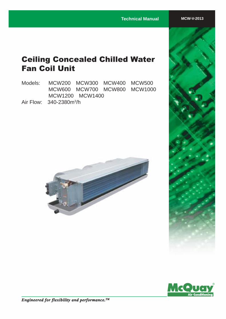
Ceiling Concealed Chilled Water Fan Coil Unit
Technical Manual
Engineered for flexibility and performance.TM
MCW-V-2013
Models: MCW200 MCW300 MCW400 MCW500 MCW600 MCW700 MCW800 MCW1000 MCW1200 MCW1400Air Flow: 340-2380m3/h

1
“McQuay” is a registered trademark of McQuay International. All rights reserved throughout the world.
© 2013 McQuay International
“Bulletin illustrations cover the general appearance of McQuay International products at the time of publicationand we reserve the right to make changes in design and construction at any time without notice.”
NOTE: Installation and maintenance are to be performed only by qualified personnel who are familiar with local codes and regulations, and experienced with this type of equipment.
Caution: Sharp edges and coil surfaces are a potential injury hazard. Avoid contact with them.
Warning: Moving machinery and electrical power hazard. May cause severe personal injury or death. Disconnect and lock off power before servicing equipment.
Literature No.: TM-MCW-V-1310A
Supersedes:
Part No.: M08039130028
Contents
Nomenclature …………………………………………………………………………………… 2
Valve Nomenclature …………………………………………………………………………… 3
Features ………………………………………………………………………………………… 4
Specifications …………………………………………………………………………………… 5
Sound Data ……………………………………………………………………………………… 6
Air Flow vs ESP Curve ………………………………………………………………………… 7
Operating Limits ………………………………………………………………………………… 8
Water Flow Rate/Pressure Drop Chart ……………………………………………………… 9
Outlines and Dimensions……………………………………………………………………… 10
Electrical Data …………………………………………………………………………………… 11
Wiring Diagrams ………………………………………………………………………………… 12
Installation ……………………………………………………………………………………… 13
2
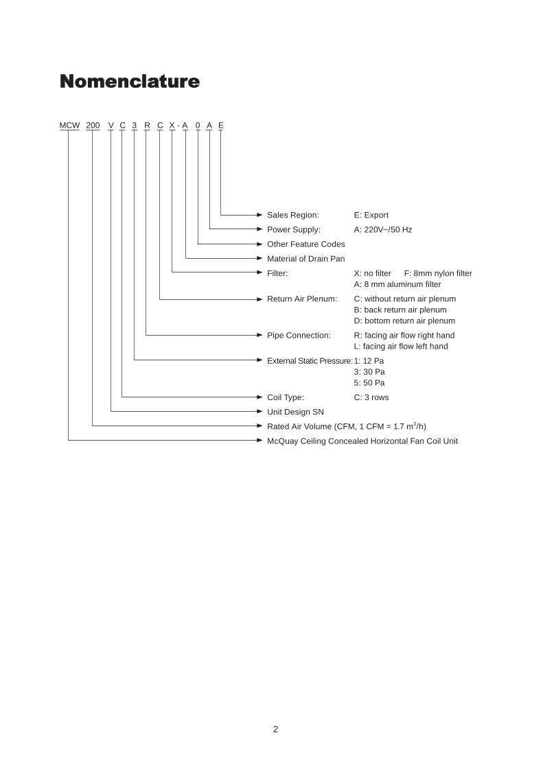
Nomenclature
MCW 200 V C 3 R C X - A 0 A E
Sales Region: E: Export
Power Supply: A: 220V~/50 Hz
Other Feature Codes
Material of Drain Pan
Filter: X: no filter F: 8mm nylon filter A: 8 mm aluminum filter
Return Air Plenum: C: without return air plenum B: back return air plenum D: bottom return air plenum
Pipe Connection: R: facing air flow right hand L: facing air flow left hand
External Static Pressure: 1: 12 Pa 3: 30 Pa 5: 50 Pa
Coil Type: C: 3 rows
Unit Design SN
Rated Air Volume (CFM, 1 CFM = 1.7 m3/h)
McQuay Ceiling Concealed Horizontal Fan Coil Unit
3
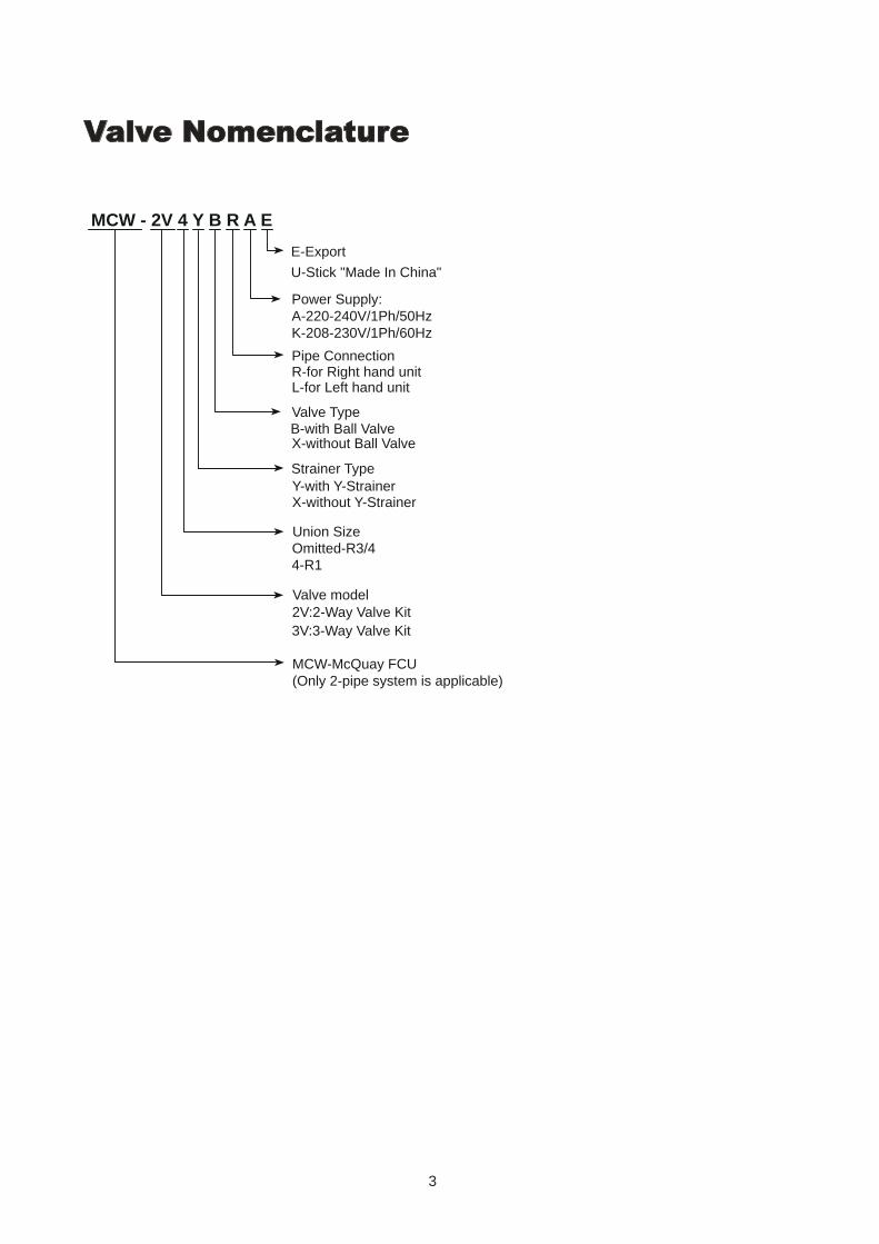
Valve Nomenclature
MCW - 2V 4 Y B R A E
MCW-McQuay FCU (Only 2-pipe system is applicable)
Valve model2V:2-Way Valve Kit3V:3-Way Valve Kit
Union SizeOmitted-R3/44-R1
Pipe ConnectionR-for Right hand unitL-for Left hand unit
E-Export
U-Stick "Made In China"
Power Supply:A-220-240V/1Ph/50HzK-208-230V/1Ph/60Hz
Valve TypeB-with Ball ValveX-without Ball Valve
Strainer TypeY-with Y-StrainerX-without Y-Strainer
4
FeaturesCompact■ Light-weighted, good-looking appearance, and compact and solid structure.■ 235 mm height, allowing installation on the ceiling with a limited space.
Low-noise■ Low-noise motor for driving the low speed fan with a wide impeller; strictly tested before delivery. ■ Precise distance between the impeller inlet/outlet and the heat exchanger for more reasonable air flow
distribution. ■ Highly efficient sound-absorbing and heat-preserving materials inside to minimize noises produced by the unit.
Reliable■ Single-phase capacitor motor with the protection grade IP20 and insulation grade B to ensure operation safety. ■ Permanently lubricated and sealed ball bearing with high precision, which is provided by internationally famous
brands and receives processing including hardening and tempering as well as chroming. ■ Motor power outlet wires protected by metal hoses to ensure its durability.■ Working pressure up to 1.6 MPa and test pressure up to 2.0 MPa for the heat exchanger to endure high
pressures and prevent leakage.
High Efficiency■ Heat exchanger with the high-quality mechanically expanded copper pipe and hydrophilic aluminum fins to
ensure high efficiency. ■ Intensified air supply using a large air flow fan with a wide impeller to maximize the heat transfer performance. ■ Precise matching of the fan and motor to guarantee the maximum cooling capacity but a low power input.
Flexible■ Multiple external static pressures designed based on the unit’s cooling capacity, meeting the air supply
requirements at different distances.■ Optional bottom return air plenum or back return air plenum with support for onsite changes, featuring time
saving. ■ Variable accessories for more options.
Anti-leakage■ Delicate condensate-proof drain pan made of the cold-rolled steel through one-time impact molding, with
coating on both sides and high-quality heat-preserving materials on the exterior.■ Unique independent mounting bracket without soldering seams or joints, requiring no bolts for fixing to prevent
damages to the drain pan heat-preserving layer or cold bridges. ■ Tilt structure for rapid condensate water drainage.
5
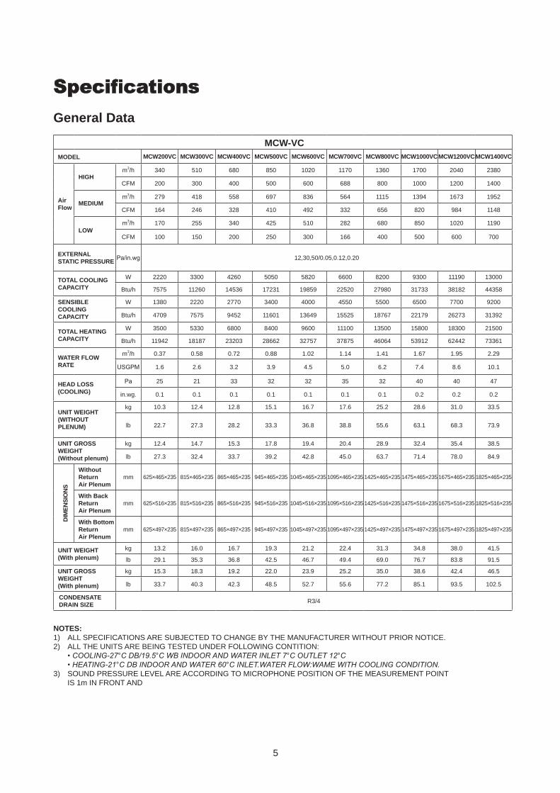
SpecificationsGeneral Data
NOTES:1) ALL SPECIFICATIONS ARE SUBJECTED TO CHANGE BY THE MANUFACTURER WITHOUT PRIOR NOTICE.2) ALL THE UNITS ARE BEING TESTED UNDER FOLLOWING CONTITION: •COOLING-27°CDB/19.5°CWBINDOORANDWATERINLET7°COUTLET12°C •HEATING-21°CDBINDOORANDWATER60°CINLET.WATERFLOW:WAMEWITHCOOLINGCONDITION.3) SOUND PRESSURE LEVEL ARE ACCORDING TO MICROPHONE POSITION OF THE MEASUREMENT POINT
IS 1m IN FRONT AND
MCW-VCMODEL MCW200VC MCW300VC MCW400VC MCW500VC MCW600VC MCW700VC MCW800VC MCW1000VCMCW1200VCMCW1400VC
Air Flow
HIGHm3/h 340 510 680 850 1020 1170 1360 1700 2040 2380
CFM 200 300 400 500 600 688 800 1000 1200 1400
MEDIUMm3/h 279 418 558 697 836 564 1115 1394 1673 1952
CFM 164 246 328 410 492 332 656 820 984 1148
LOWm3/h 170 255 340 425 510 282 680 850 1020 1190
CFM 100 150 200 250 300 166 400 500 600 700
EXTERNAL STATIC PRESSURE
Pa/in.wg 12,30,50/0.05,0.12,0.20
TOTAL COOLING CAPACITY
W 2220 3300 4260 5050 5820 6600 8200 9300 11190 13000
Btu/h 7575 11260 14536 17231 19859 22520 27980 31733 38182 44358
SENSIBLE COOLING CAPACITY
W 1380 2220 2770 3400 4000 4550 5500 6500 7700 9200
Btu/h 4709 7575 9452 11601 13649 15525 18767 22179 26273 31392
TOTAL HEATING CAPACITY
W 3500 5330 6800 8400 9600 11100 13500 15800 18300 21500
Btu/h 11942 18187 23203 28662 32757 37875 46064 53912 62442 73361
WATER FLOW RATE
m3/h 0.37 0.58 0.72 0.88 1.02 1.14 1.41 1.67 1.95 2.29
USGPM 1.6 2.6 3.2 3.9 4.5 5.0 6.2 7.4 8.6 10.1
HEAD LOSS (COOLING)
Pa 25 21 33 32 32 35 32 40 40 47
in.wg. 0.1 0.1 0.1 0.1 0.1 0.1 0.1 0.2 0.2 0.2
UNIT WEIGHT(WITHOUT PLENUM)
kg 10.3 12.4 12.8 15.1 16.7 17.6 25.2 28.6 31.0 33.5
lb 22.7 27.3 28.2 33.3 36.8 38.8 55.6 63.1 68.3 73.9
UNIT GROSS WEIGHT(Without plenum)
kg 12.4 14.7 15.3 17.8 19.4 20.4 28.9 32.4 35.4 38.5
lb 27.3 32.4 33.7 39.2 42.8 45.0 63.7 71.4 78.0 84.9
DIM
EN
SIO
NS
Without Return Air Plenum
mm 625×465×235 815×465×235 865×465×235 945×465×235 1045×465×235 1095×465×235 1425×465×235 1475×465×235 1675×465×235 1825×465×235
With Back Return Air Plenum
mm 625×516×235 815×516×235 865×516×235 945×516×235 1045×516×235 1095×516×235 1425×516×235 1475×516×235 1675×516×235 1825×516×235
With Bottom Return Air Plenum
mm 625×497×235 815×497×235 865×497×235 945×497×235 1045×497×235 1095×497×235 1425×497×235 1475×497×235 1675×497×235 1825×497×235
UNIT WEIGHT(With plenum)
kg 13.2 16.0 16.7 19.3 21.2 22.4 31.3 34.8 38.0 41.5
lb 29.1 35.3 36.8 42.5 46.7 49.4 69.0 76.7 83.8 91.5
UNIT GROSS WEIGHT(With plenum)
kg 15.3 18.3 19.2 22.0 23.9 25.2 35.0 38.6 42.4 46.5
lb 33.7 40.3 42.3 48.5 52.7 55.6 77.2 85.1 93.5 102.5
CONDENSATE DRAIN SIZE
R3/4
6
NOTES:ALL SPECIFICATIONS ARE SUBJECTED TO CHANGE BY THE MANUFACTURER WITHOUT PRIOR NOTICE.
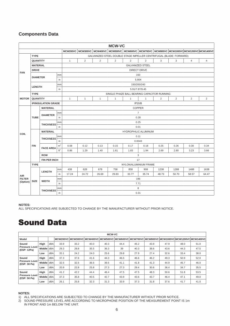
Components Data
MCW-VCMCW200VC MCW300VC MCW400VC MCW500VC MCW600VC MCW700VC MCW800VC MCW1000VC MCW1200VC MCW1400VC
FAN
TYPE GALVANIZED STEEL DOUBLE STAGE IMPELLER CENTRIFUGAL (BLADE: FORWARD)
QUANTITY 1 2 2 2 2 2 3 3 4 4
MATERIAL GALVANIZED STEEL
DRIVE DIRECT DRIVE
DIAMETERmm 150
in 5.904
LENGTHmm 150/200/240
in 5.91/7.87/9.45
MOTOR
TYPE SINGLE PHAZE BALL BEARING CAPACITOR RUNNING
QUANTITY 1 1 1 1 1 1 2 2 2 2
IP/INSULATION GRADE IP20/B
COIL
TUBE
MATERIAL COPPER
DIAMETERmm 7
in 0.28
THICKNESSmm 0.25
in 0.01
FIN
MATERIAL HYDROPHILIC ALUMINUM
THICKNESSmm 0.11
in 0.0043
FACE AREAm2 0.08 0.12 0.13 0.15 0.17 0.18 0.25 0.26 0.30 0.34
ft2 0.86 1.29 1.40 1.61 1.83 1.94 2.69 2.80 3.23 3.66
ROW 3
FIN PER INCH 17
AIR FILTER (Option)
TYPE NYLON/ALUMINIUM FRAME
SIZE
LENGTHmm 438 628 678 758 858 908 1238 1288 1488 1638
in 17.24 24.72 26.69 29.83 33.77 35.74 48.73 50.70 58.57 64.47
WIDTHmm 196
in 7.71
THICKNESSmm 8
in 0.31
NOTES:1) ALL SPECIFICATIONS ARE SUBJECTED TO CHANGE BY THE MANUFACTURER WITHOUT PRIOR NOTICE.2) SOUND PRESSURE LEVEL ARE ACCORDING TO MICROPHONE POSITION OF THE MEASUREMENT POINT IS 1m
IN FRONT AND 1m BELOW THE UNIT.
Sound DataMCW-VC
Model MCW200VC MCW300VC MCW400VC MCW500VC MCW600VC MCW700VC MCW800VC MCW1000VC MCW1200VC MCW1400VC
Sound Pressure Level (ESP: 12Pa)
High dBA 33.9 33.2 40.0 40.3 44.4 45.2 43.9 47.9 48.0 51.0
Middle dBA 29.3 28.8 35.5 36.3 39 40.3 38.6 43.6 44.3 47.5
Low dBA 20.1 24.2 24.0 25.6 29.8 27.9 27.4 32.6 33.4 38.0
Sound Pressure Level (ESP: 30 Pa)
High dBA 37.3 37.6 41.6 44.3 46.5 46.6 46.2 49.3 50.9 52.0
Middle dBA 32.5 32.5 36.5 39.5 41.1 41.8 41.3 44.9 45.7 46.0
Low dBA 20.9 22.8 25.8 27.3 27.3 29.4 30.6 36.4 34.7 35.5
Sound Pressure Level (ESP: 50 Pa)
High dBA 41.2 42.2 44.4 46.4 47.5 47.5 48.3 50.6 51.8 53.5
Middle dBA 37.3 35.8 40.5 42.7 43.9 43.6 43.7 46.4 47.1 49.0
Low dBA 26.1 25.8 32.3 31.3 33.9 37.3 31.8 37.6 41.7 41.0
7
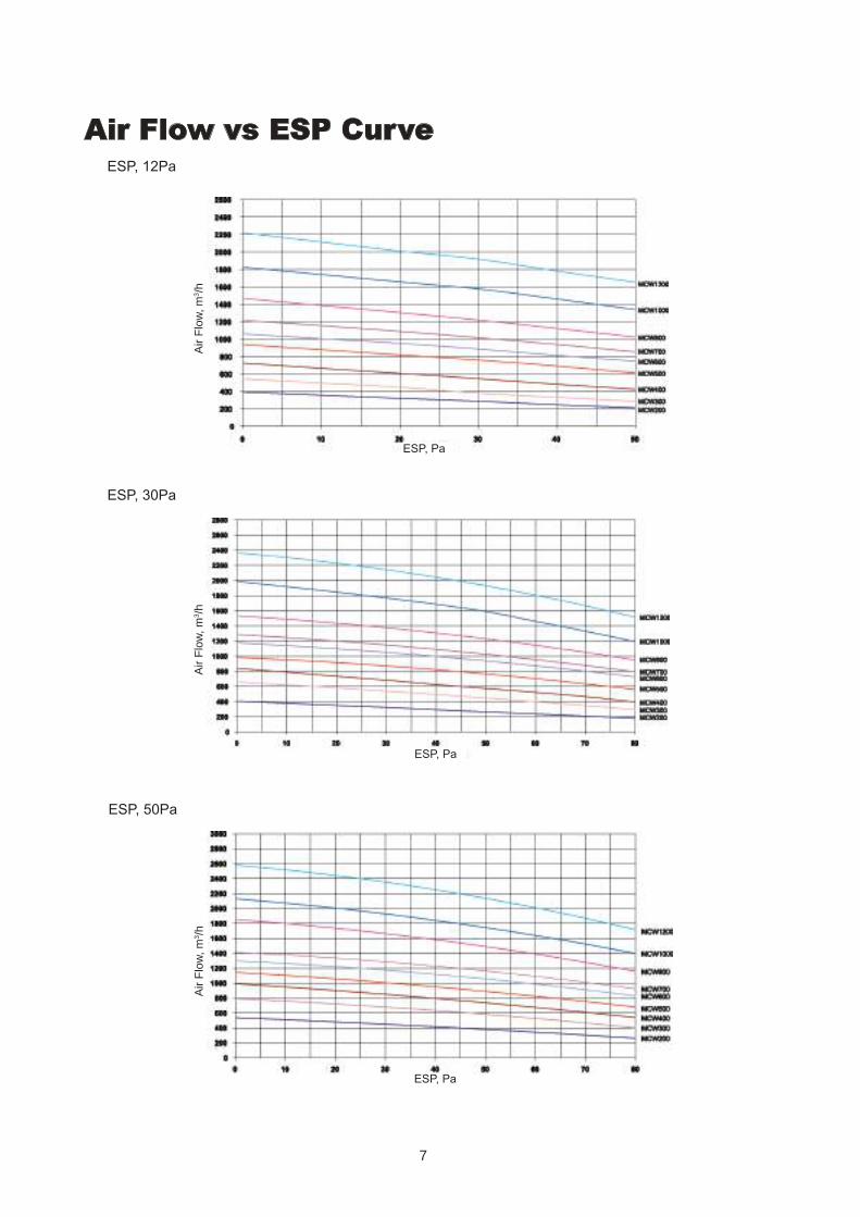
ESP, 12Pa
ESP, Pa
Air Flow vs ESP Curve
ESP, 30Pa
ESP, 50Pa
Air
Flo
w, m
3 /h
Air
Flo
w, m
3 /h
Air
Flo
w, m
3 /h
ESP, Pa
ESP, Pa
8
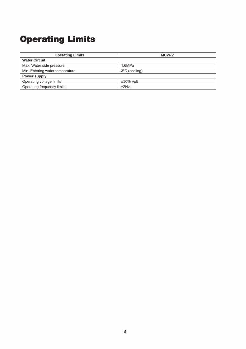
Operating Limits
Operating Limits MCW-VWater Circuit Max. Water side pressure 1.6MPa Min. Entering water temperature 3ºC (cooling) Power supply Operating voltage limits ±10% Volt Operating frequency limits ±2Hz
9
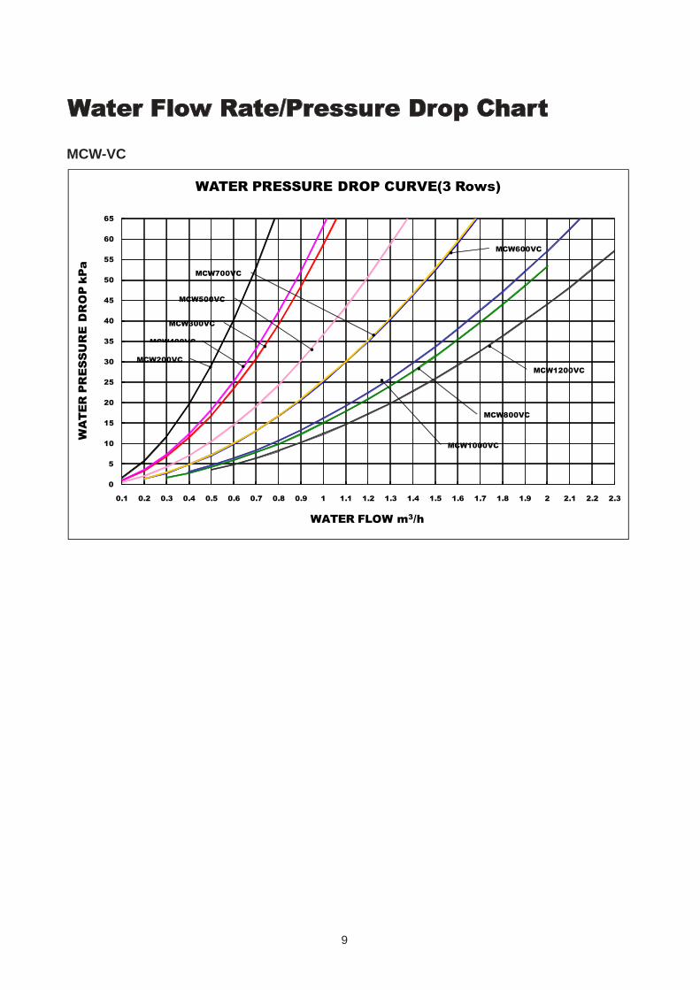
Water Flow Rate/Pressure Drop Chart
MCW-VC
0
5
10
15
20
25
30
35
40
45
50
55
60
65
0.1 0.2 0.3 0.4 0.5 0.6 0.7 0.8 0.9 1 1.1 1.2 1.3 1.4 1.5 1.6 1.7 1.8 1.9 2 2.1 2.2 2.3
WA
TE
R P
RE
SS
UR
E D
RO
P k
Pa
WATER FLOW m3/h
WATER PRESSURE DROP CURVE(3 Rows)
MCW300VC
MCW200VC
MCW400VC
MCW500VC
MCW700VC
MCW1000VC
MCW800VC
MCW600VC
MCW1200VC
10
3014
3
226
35
187
44
D
A
BC
235 15
114
465105
20
262
131242
40
MCW400V
MCW600V
MCW500V
MCW1000V
MCW1200V
MCW800V
MCW300V
16751475
945
1425
1045
625
865815
AC
437
677
857
757
1237
1287
1487
627
1202
1252
1452
822
722
402
642
592
B D
1775
1575
1525
1145
1045
965915
725
MCW700V 1095 1195 872 907
440
630
680
760
860
910
1240
1290
1490
F
420
610
660
740
840
890
1220
1270
1470
2
2
2
3
4
2
3
1
2
3014
3
226
35
187
44 A
BC
235 15
1
262
131242
516
232
180
E
146
F
40
G
3014
3
226
35
187
44
A
BC
38
235 15
1
105
262
131242
497
232
E
146
16
217
(175
)
40 MCW200V
MCW400V
MCW600V
MCW500V
MCW1000V
MCW1200V
MCW800V
MCW300V
16751475
945
1425
1045
625
865815
AC
437
677
857
757
1237
1287
1487
627
1202
1252
1452
822
722
402
642
592
B D
2
2
2
3
4
2
3
1
1775
1575
1525
1145
1045
965915
725
MCW700V 1095 1195 872 907 2
440
630
680
760
860
910
1240
1290
1490
892
792
1272
1322
1522
E
472
712
662
942
G
441
581
681
761
861
911
1241
1291
1491
MCW200V
MCW400V
MCW600V
MCW500V
MCW1000V
MCW1200V
MCW800V
MCW300V
16751475
945
1425
1045
625
865
815
AC
437
677
857
757
1237
1287
1487
627
1202
1252
1452
822
722
402
642592
B D
2
2
2
34
2
3
1
177515751525
11451045965915725
MCW700V 1095 1195 872 907 2
440630680760860910124012901490
892792
127213221522
E
472
712662
942
20°
8
75
MCW1400V 1825 163716021925 1640 4
MCW1400V 1825 1925 162016371602 41640 1672
MCW1400V 1825 1925 16371602 41640 1672 1641
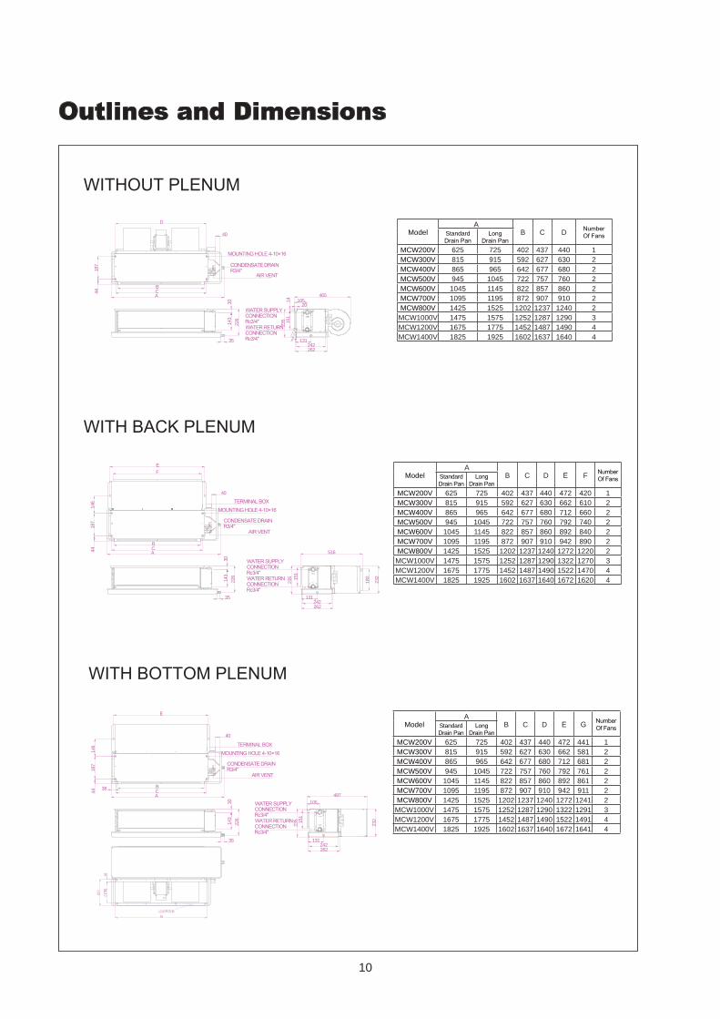
WITHOUT PLENUM
CONDENSATE DRAIN R3/4″
MOUNTING HOLE 4-10×16
AIR VENT
WATER SUPPLY CONNECTION Rc3/4″WATER RETURN CONNECTION Rc3/4″
Model Standard Drain Pan
Long Drain Pan
Number Of Fans
MCW200V
WITH BACK PLENUM
TERMINAL BOXMOUNTING HOLE 4-10×16
CONDENSATE DRAIN R3/4″
AIR VENT
WATER SUPPLY CONNECTION Rc3/4″WATER RETURN CONNECTION Rc3/4″
Model Standard Drain Pan
Long Drain Pan
Number Of Fans
Standard Drain Pan
Model Long Drain Pan
Number Of Fans
WITH BOTTOM PLENUM
TERMINAL BOXMOUNTING HOLE 4-10×16
CONDENSATE DRAIN R3/4″
AIR VENT
WATER SUPPLY CONNECTION Rc3/4″WATER RETURN CONNECTION Rc3/4″
Outlines and Dimensions
ModelA
B C D Number Of FansStandard
Drain PanLong
Drain PanMCW200V 625 725 402 437 440 1MCW300V 815 915 592 627 630 2MCW400V 865 965 642 677 680 2MCW500V 945 1045 722 757 760 2MCW600V 1045 1145 822 857 860 2MCW700V 1095 1195 872 907 910 2MCW800V 1425 1525 1202 1237 1240 2MCW1000V 1475 1575 1252 1287 1290 3MCW1200V 1675 1775 1452 1487 1490 4MCW1400V 1825 1925 1602 1637 1640 4
ModelA
B C D E F Number Of FansStandard
Drain PanLong
Drain PanMCW200V 625 725 402 437 440 472 420 1MCW300V 815 915 592 627 630 662 610 2MCW400V 865 965 642 677 680 712 660 2MCW500V 945 1045 722 757 760 792 740 2MCW600V 1045 1145 822 857 860 892 840 2MCW700V 1095 1195 872 907 910 942 890 2MCW800V 1425 1525 1202 1237 1240 1272 1220 2MCW1000V 1475 1575 1252 1287 1290 1322 1270 3MCW1200V 1675 1775 1452 1487 1490 1522 1470 4MCW1400V 1825 1925 1602 1637 1640 1672 1620 4
ModelA
B C D E G Number Of FansStandard
Drain PanLong
Drain PanMCW200V 625 725 402 437 440 472 441 1MCW300V 815 915 592 627 630 662 581 2MCW400V 865 965 642 677 680 712 681 2MCW500V 945 1045 722 757 760 792 761 2MCW600V 1045 1145 822 857 860 892 861 2MCW700V 1095 1195 872 907 910 942 911 2MCW800V 1425 1525 1202 1237 1240 1272 1241 2MCW1000V 1475 1575 1252 1287 1290 1322 1291 3MCW1200V 1675 1775 1452 1487 1490 1522 1491 4MCW1400V 1825 1925 1602 1637 1640 1672 1641 4
11
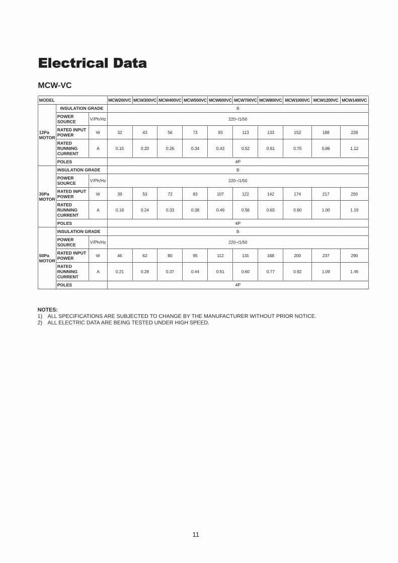
MCW-VC
Electrical Data
MODEL MCW200VC MCW300VC MCW400VC MCW500VC MCW600VC MCW700VC MCW800VC MCW1000VC MCW1200VC MCW1400VC
12Pa MOTOR
INSULATION GRADE B
POWER SOURCE
V/Ph/Hz 220~/1/50
RATED INPUT POWER
W 32 43 56 73 93 113 133 152 188 228
RATED RUNNING CURRENT
A 0.15 0.20 0.26 0.34 0.43 0.52 0.61 0.70 0.86 1.12
POLES 4P
30Pa MOTOR
INSULATION GRADE B
POWER SOURCE
V/Ph/Hz 220~/1/50
RATED INPUT POWER
W 39 53 72 83 107 122 142 174 217 250
RATED RUNNING CURRENT
A 0.18 0.24 0.33 0.38 0.49 0.56 0.65 0.80 1.00 1.19
POLES 4P
50Pa MOTOR
INSULATION GRADE B
POWER SOURCE
V/Ph/Hz 220~/1/50
RATED INPUT POWER
W 46 62 80 95 112 131 168 200 237 290
RATED RUNNING CURRENT
A 0.21 0.28 0.37 0.44 0.51 0.60 0.77 0.92 1.09 1.45
POLES 4P
NOTES:1) ALL SPECIFICATIONS ARE SUBJECTED TO CHANGE BY THE MANUFACTURER WITHOUT PRIOR NOTICE.2) ALL ELECTRIC DATA ARE BEING TESTED UNDER HIGH SPEED.
12
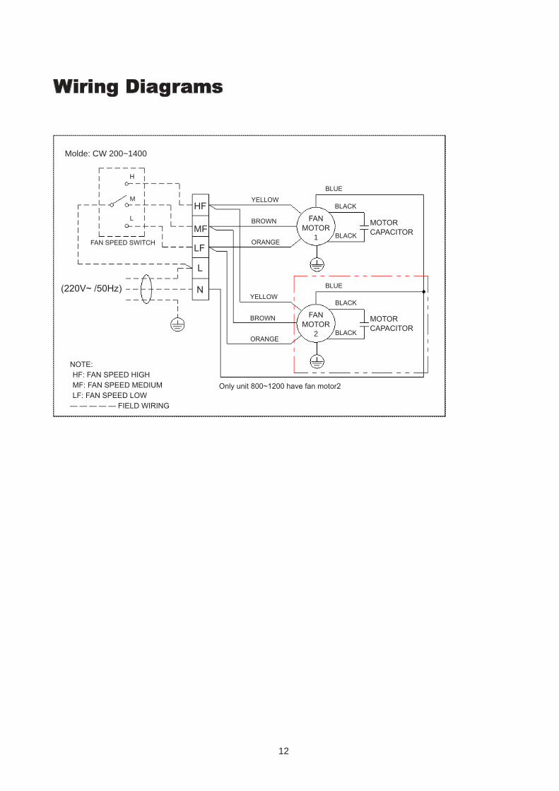
Wiring Diagrams
Molde: CW 200~1400
H
M
L
FAN SPEED SWITCH
HF
MF
N(220V~ /50Hz)
YELLOW
BROWN
ORANGE
YELLOW
BROWN
ORANGE
BLUE
BLACK
BLACK
BLACK
BLACK
BLUE
MOTOR CAPACITOR
MOTOR CAPACITOR
FAN MOTOR
1
FAN MOTOR
2
Only unit 800~1200 have fan motor2
NOTE:HF: FAN SPEED HIGHMF: FAN SPEED MEDIUMLF: FAN SPEED LOW
— — — — — FIELD WIRING
LF
L
13
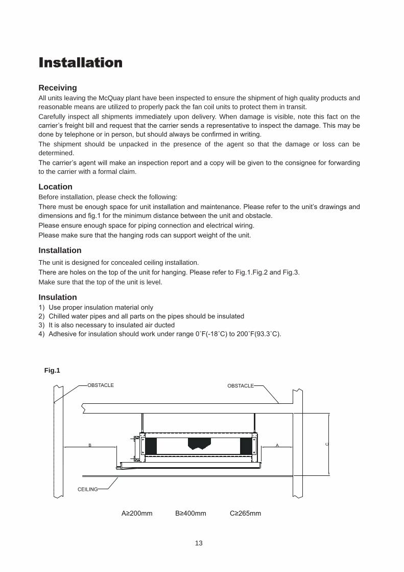
InstallationReceivingAll units leaving the McQuay plant have been inspected to ensure the shipment of high quality products and reasonable means are utilized to properly pack the fan coil units to protect them in transit.Carefully inspect all shipments immediately upon delivery. When damage is visible, note this fact on the carrier’s freight bill and request that the carrier sends a representative to inspect the damage. This may be done by telephone or in person, but should always be confirmed in writing.The shipment should be unpacked in the presence of the agent so that the damage or loss can be determined.The carrier’s agent will make an inspection report and a copy will be given to the consignee for forwarding to the carrier with a formal claim.
LocationBefore installation, please check the following:There must be enough space for unit installation and maintenance. Please refer to the unit’s drawings and dimensions and fig.1 for the minimum distance between the unit and obstacle.Please ensure enough space for piping connection and electrical wiring.Please make sure that the hanging rods can support weight of the unit.
InstallationThe unit is designed for concealed ceiling installation.There are holes on the top of the unit for hanging. Please refer to Fig.1.Fig.2 and Fig.3.Make sure that the top of the unit is level.
Insulation1) Use proper insulation material only2) Chilled water pipes and all parts on the pipes should be insulated3) It is also necessary to insulated air ducted4) Adhesive for insulation should work under range 0˚F(-18˚C) to 200˚F(93.3˚C).
Fig.1
CEILING
OBSTACLE
B CA
OBSTACLE
A≥200mm B≥400mm C≥265mm
14
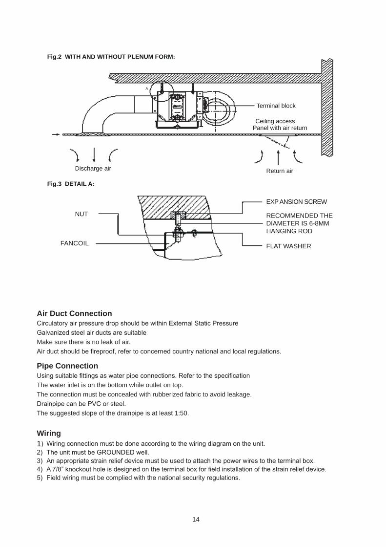
Fig.2 WITH AND WITHOUT PLENUM FORM:
Fig.3 DETAIL A:
Return airDischarge air
Terminal block
Ceiling accessPanel with air return
A
NUT
FANCOIL
EXP ANSION SCREW
RECOMMENDED THE DIAMETER IS 6-8MM HANGING ROD
FLAT WASHER
Air Duct ConnectionCirculatory air pressure drop should be within External Static PressureGalvanized steel air ducts are suitableMake sure there is no leak of air.Air duct should be fireproof, refer to concerned country national and local regulations.
Pipe ConnectionUsing suitable fittings as water pipe connections. Refer to the specificationThe water inlet is on the bottom while outlet on top.The connection must be concealed with rubberized fabric to avoid leakage.Drainpipe can be PVC or steel.The suggested slope of the drainpipe is at least 1:50.
Wiring1) Wiring connection must be done according to the wiring diagram on the unit.2) The unit must be GROUNDED well.3) An appropriate strain relief device must be used to attach the power wires to the terminal box.4) A 7/8” knockout hole is designed on the terminal box for field installation of the strain relief device.5) Field wiring must be complied with the national security regulations.
15
EF
D
CB
A
E
F A
B
C
D
G
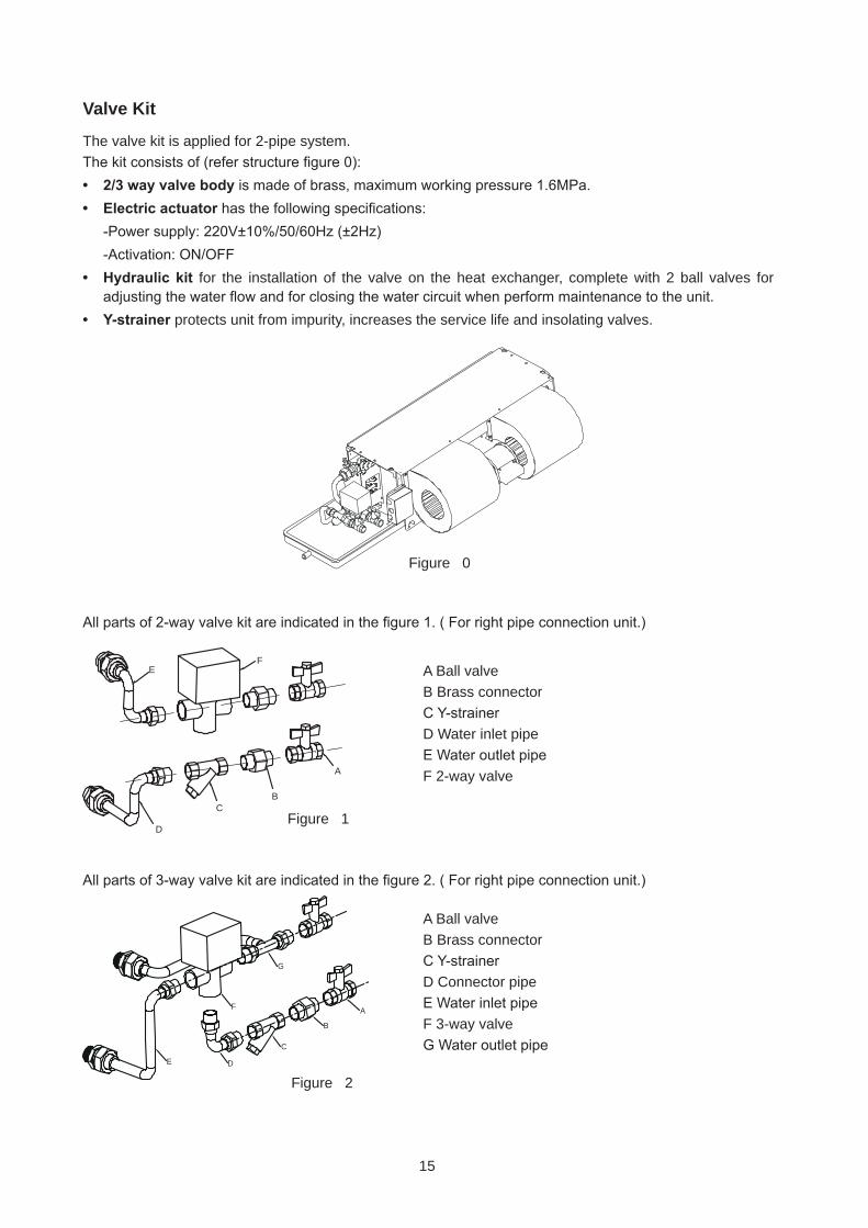
Valve Kit
The valve kit is applied for 2-pipe system.The kit consists of (refer structure figure 0):• 2/3 way valve body is made of brass, maximum working pressure 1.6MPa.• Electric actuator has the following specifications: -Power supply: 220V±10%/50/60Hz (±2Hz) -Activation: ON/OFF• Hydraulic kit for the installation of the valve on the heat exchanger, complete with 2 ball valves for
adjusting the water flow and for closing the water circuit when perform maintenance to the unit.• Y-strainer protects unit from impurity, increases the service life and insolating valves.
All parts of 2-way valve kit are indicated in the figure 1. ( For right pipe connection unit.)
All parts of 3-way valve kit are indicated in the figure 2. ( For right pipe connection unit.)
Figure 1
Figure 2
A Ball valveB Brass connectorC Y-strainerD Water inlet pipeE Water outlet pipeF 2-way valve
A Ball valveB Brass connectorC Y-strainerD Connector pipeE Water inlet pipeF 3-way valveG Water outlet pipe
Figure 0
16
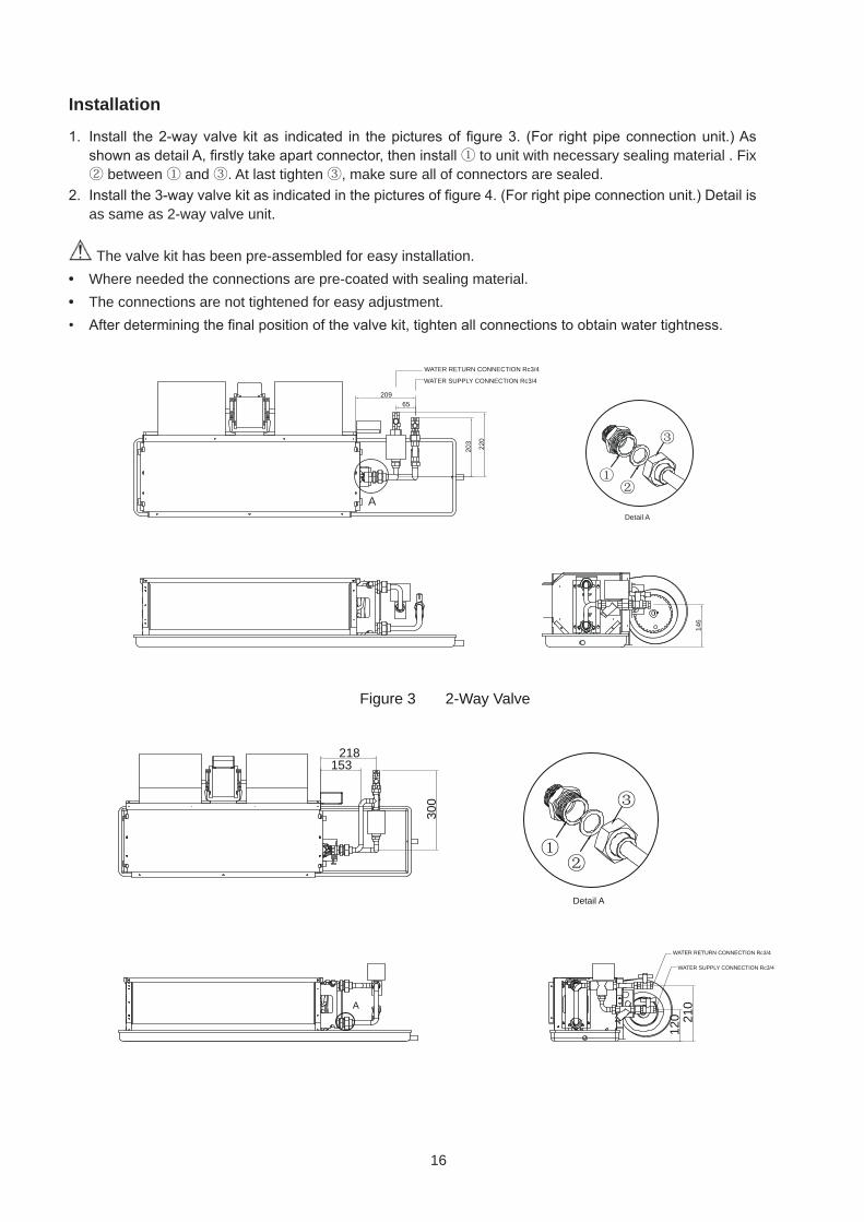
Installation
1. Install the 2-way valve kit as indicated in the pictures of figure 3. (For right pipe connection unit.) As shown as detail A, firstly take apart connector, then install ① to unit with necessary sealing material . Fix ② between ① and ③. At last tighten ③, make sure all of connectors are sealed.
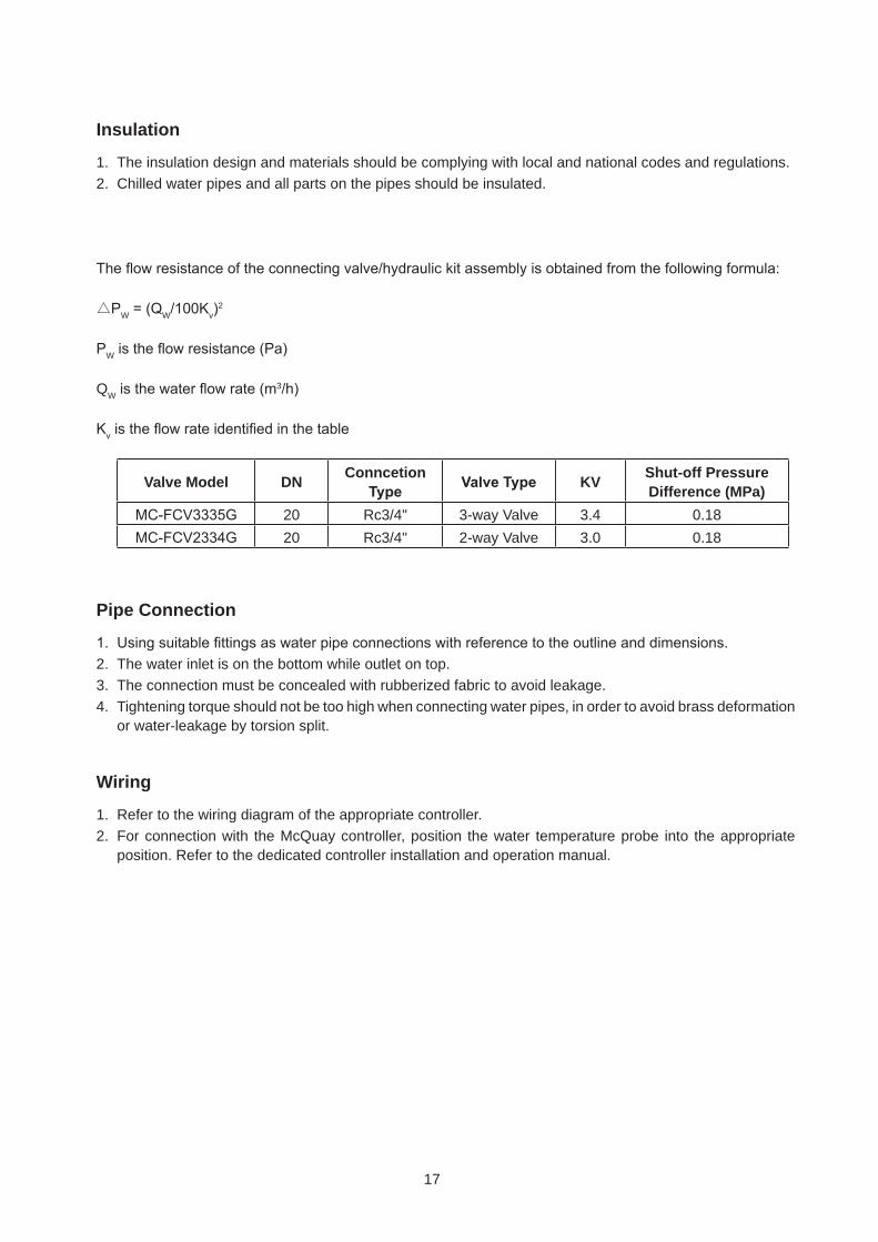
2. Install the 3-way valve kit as indicated in the pictures of figure 4. (For right pipe connection unit.) Detail is as same as 2-way valve unit.
The valve kit has been pre-assembled for easy installation.
• Where needed the connections are pre-coated with sealing material.
• The connections are not tightened for easy adjustment.
• After determining the final position of the valve kit, tighten all connections to obtain water tightness.
220
203
146
65209
WATER RETURN CONNECTION Rc3/4
WATER SUPPLY CONNECTION Rc3/4
Figure 3 2-Way Valve
ADetail A
153218
300
120 21
0A
Detail A
WATER SUPPLY CONNECTION Rc3/4
WATER RETURN CONNECTION Rc3/4
17
Insulation
1. The insulation design and materials should be complying with local and national codes and regulations.2. Chilled water pipes and all parts on the pipes should be insulated.
The flow resistance of the connecting valve/hydraulic kit assembly is obtained from the following formula:
△PW = (QW/100Kv)2
PW is the flow resistance (Pa)
QW is the water flow rate (m3/h)
Kv is the flow rate identified in the table
Valve Model DNConncetion
Type Valve Type KVShut-off Pressure Difference (MPa)
MC-FCV3335G 20 Rc3/4" 3-way Valve 3.4 0.18
MC-FCV2334G 20 Rc3/4" 2-way Valve 3.0 0.18
Pipe Connection
1. Using suitable fittings as water pipe connections with reference to the outline and dimensions.2. The water inlet is on the bottom while outlet on top.3. The connection must be concealed with rubberized fabric to avoid leakage.4. Tightening torque should not be too high when connecting water pipes, in order to avoid brass deformation
or water-leakage by torsion split.
Wiring
1. Refer to the wiring diagram of the appropriate controller.2. For connection with the McQuay controller, position the water temperature probe into the appropriate
position. Refer to the dedicated controller installation and operation manual.

©2013 McQuay International +1 (800) 432-1342 www.mcquay.com
While utmost care is taken in ensuring that all details in the publication are correct at the time of going
to press, we are constantly striving for improvement and therefore reserve the right to alter model
specifications and equipment without notice.Details of specifications and equipment are also subject to change to suit local conditions and requirements and not all models are available in every market.
ISO 9001 Certificate No.: 9601019
BS-OHSAS 18001 Certificate No.: 7644
ISO 14001 Certificate No.: EMS 80362
Related Documents