MPH Filter housing (Materials) • Head: Aluminium: MPH 104-110-114-120-250 Anodised Aluminium: MPH 630-850 Painted Aluminium: MPH 660 • Cover:Nylon: MPH 104-110-114-120 Aluminium: MPH 250 Anodised Aluminium: MPH 630 Painted Aluminium: MPH 660 Steel: MPH 850 • Insert assembly: Nylon (only for: MPH 104-110-114-120) Aluminium (all the other) • Diffuser: Zinc Plated Steel (excluded MPH 850) Tinned Steel: MPH 850 • Valve: Phosphated Steel Pressure • Working pressure: 10 bar (1 MPa) Temperature • From -25°C to +110°C Bypass valve • Opening pressure 1,75 bar ±10% • Opening pressure 2,5 bar ±10% (excluded for MPH 850) Δp Elements type • Microfibre filter elements series MR: 10 bar • Fluid flow through the filter element from IN to OUT. Seals • Standard NBR series A • Optional FPM series V MPH FILTERS ARE PROVIDED FOR VERTICAL MOUNTING Weights (kg) Length 1 2 3 4 5 • MPH 104-110 1,60 1,70 1,80 2,20 2,60 • MPH 114-120 1,60 1,70 1,80 2,20 2,60 • MPH 250 3,60 3,90 4,20 5,60 - • MPH 630 6,50 7,00 7,40 8,50 10,50 • MPH 660 - - - 11,5 14 • MPH 850 32 35 38 42 - Volumes (dm 3 ) Length 1 2 3 4 • MPH 104-110 1,60 1,70 1,80 2,20 2,60 • MPH 114-120 1,60 1,70 1,80 2,20 2,60 • MPH 250 4,40 4,40 5,40 8,00 - • MPH 630 7,30 9,00 11,0 13 19,2 • MPH 660 - - - 14,6 21 • MPH 850 13 16,5 21 25 - Filter housings Δp pressure drop The curves are plotted utilising mineral oil with density of 0,86 kg/dm 3 to ISO 3968. Δp varies proportionally with density. Maximum pressure 10 bar Flow rates to 3000 l/min T T e e c c h h n n i i c c a a l l d d a a t t a a 0,1 0,075 0,05 0,025 0 Δp bar 0 80 160 240 320 400 Flow rate l/min MPH 104 - 110 - 114 - 120 3/4” 1 1/4” 1” 0,16 0,12 0,08 0,04 0 MPH 250 Δp bar 0 120 240 360 480 600 Flow rate l/min 1 1/4” 0,16 0,12 0,08 0,04 0 MPH 630 Δp bar 0 240 480 720 960 1200 Flow rate l/min 1 1/2” RETURN FILTER 82

Welcome message from author
This document is posted to help you gain knowledge. Please leave a comment to let me know what you think about it! Share it to your friends and learn new things together.
Transcript
MPH
Filter housing (Materials)
• Head: Aluminium: MPH 104-110-114-120-250
Anodised Aluminium: MPH 630-850
Painted Aluminium: MPH 660
• Cover:Nylon: MPH 104-110-114-120
Aluminium: MPH 250
Anodised Aluminium: MPH 630
Painted Aluminium: MPH 660
Steel: MPH 850
• Insert assembly: Nylon (only for: MPH 104-110-114-120)
Aluminium (all the other)
• Diffuser: Zinc Plated Steel (excluded MPH 850)
Tinned Steel: MPH 850
• Valve: Phosphated Steel
Pressure
• Working pressure: 10 bar (1 MPa)
Temperature
• From -25°C to +110°C
Bypass valve
• Opening pressure 1,75 bar ±10%
• Opening pressure 2,5 bar ±10% (excluded for MPH 850)
Δp Elements type
• Microfibre filter elements series MR: 10 bar
• Fluid flow through the filter element from IN to OUT.
Seals
• Standard NBR series A
• Optional FPM series V
MPH FILTERS ARE PROVIDED FOR VERTICAL MOUNTING
Weights (kg)
Length 1 2 3 4 5
• MPH 104-110 1,60 1,70 1,80 2,20 2,60
• MPH 114-120 1,60 1,70 1,80 2,20 2,60
• MPH 250 3,60 3,90 4,20 5,60 -
• MPH 630 6,50 7,00 7,40 8,50 10,50
• MPH 660 - - - 11,5 14
• MPH 850 32 35 38 42 -
Volumes (dm3)
Length 1 2 3 4
• MPH 104-110 1,60 1,70 1,80 2,20 2,60
• MPH 114-120 1,60 1,70 1,80 2,20 2,60
• MPH 250 4,40 4,40 5,40 8,00 -
• MPH 630 7,30 9,00 11,0 13 19,2
• MPH 660 - - - 14,6 21
• MPH 850 13 16,5 21 25 -
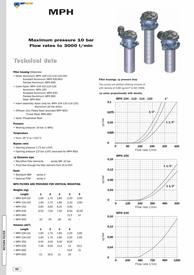
Filter housings Δp pressure drop
The curves are plotted utilising mineral oil
with density of 0,86 kg/dm3 to ISO 3968.
Δp varies proportionally with density.
Maximum pressure 10 bar
Flow rates to 3000 l/min
TTeecchhnniiccaall ddaattaa
MPH 100
0,1
0,075
0,05
0,025
0
Δp b
ar
0 80 160 240 320 400Flow rate l/min
MPH 104 - 110 - 114 - 120
3/4”
1 1/4”
1”
0,16
0,12
0,08
0,04
0
MPH 250
Δp b
ar
0 120 240 360 480 600Flow rate l/min
1 1/4”
0,16
0,12
0,08
0,04
0
MPH 630
Δp b
ar
0 240 480 720 960 1200Flow rate l/min
1 1/2”
RETU
RN FILTE
R
82
MPH 660
0,40
0,30
0,20
0,10
0
MPH 850
Δp b
ar
0 600 1200 1800 2400 3000Flow rate l/min
MPH 660
0,40
0,30
0,20
0,10
0
MPH 660Δ
p b
ar
0 480 960 1440 1920 2400Flow rate l/min
DN 100
DN 80
DN 100
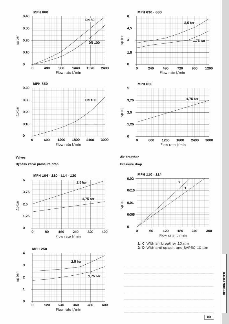
Valves
Bypass valve pressure drop
MPH 104 - 110 - 114 - 120
Δp b
ar
5
3,75
2,5
1,25
00 80 160 240 320 400
Flow rate l/min
2,5 bar
1,75 bar
MPH 2504
3
2
1
0
Δp b
ar
0 120 240 360 480 600Flow rate l/min
2,5 bar
1,75 bar
MPH 630 - 660
MPH 850
5
3,75
2,5
1,25
0
MPH 850
Δp b
ar
0 600 1200 1800 2400 3000Flow rate l/min
6
4,5
3
1,5
0
Δp b
ar
0 240 480 720 960 1200Flow rate l/min
1,75 bar
2,5 bar
1,75 bar
Air breather
Pressure drop
MPH 110 - 1140,02
0,015
0,01
0,005
0
Δp b
ar
0 60 120 180 240 300Flow rate lN /min
1: C With air breather 10 μm
2: D With anti-splash and SAP50 10 μm
2
1
RETU
RN FILTE
R
83
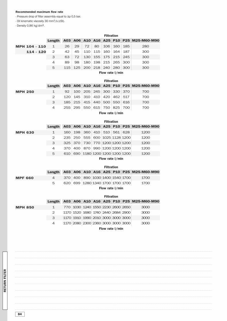
Recommended maximum flow rate
- Pressure drop of filter assembly equal to Δp 0,5 bar.
- Oil kinematic viscosity 30 mm2/s (cSt).
- Density 0,86 kg/dm3.
Flow rate l/min
Filtration
Flow rate l/min
A03 A06 A10 A16 A25 P10 P25 M25-M60-M90Length
370
620
400
699
890
1280
1030
1340
1540
1700
4
5
1400
1700
1700
1700
1700
1700
MPF 660
Filtration
A03 A06 A10 A16 A25 P10 P25 M25-M60-M90Length
26
42
63
89
115
29
45
72
98
125
72
110
130
180
200
80
115
155
198
218
160
164
215
265
280
1
2
3
4
5
106
160
175
215
240
185
187
245
300
300
280
300
300
300
300
MPH 104 - 110
114 - 120
Filtration
Flow rate l/min
A03 A06 A10 A16 A25 P10 P25 M25-M60-M90Length
92
120
185
255
100
145
215
295
205
310
415
550
245
410
440
615
330
462
550
825
1
2
3
4
300
420
500
750
370
517
616
700
700
700
700
700
MPH 250
Flow rate l/min
Filtration
A03 A06 A10 A16 A25 P10 P25 M25-M60-M90Length
160
235
325
370
610
198
250
370
400
690
360
555
730
870
1180
410
600
770
990
1200
561
1128
1200
1200
1200
1
2
3
4
5
510
1025
1200
1200
1200
628
1200
1200
1200
1200
1200
1200
1200
1200
1200
MPH 630
Filtration
Flow rate l/min
A03 A06 A10 A16 A25 P10 P25 M25-M60-M90Length
1030
1520
1910
2080
1240
1680
1990
2300
1550
1740
2010
2360
2600
2684
3000
3000
1
2
3
4
2230
2440
3000
3000
2650
2900
3000
3000
3000
3000
3000
3000
MPH 850 770
1170
1170
1170
RETU
RN FILTE
R
84
H1
12
40 32H2
H3
80
97
Ø 86
Holes on the tank
56
A
68
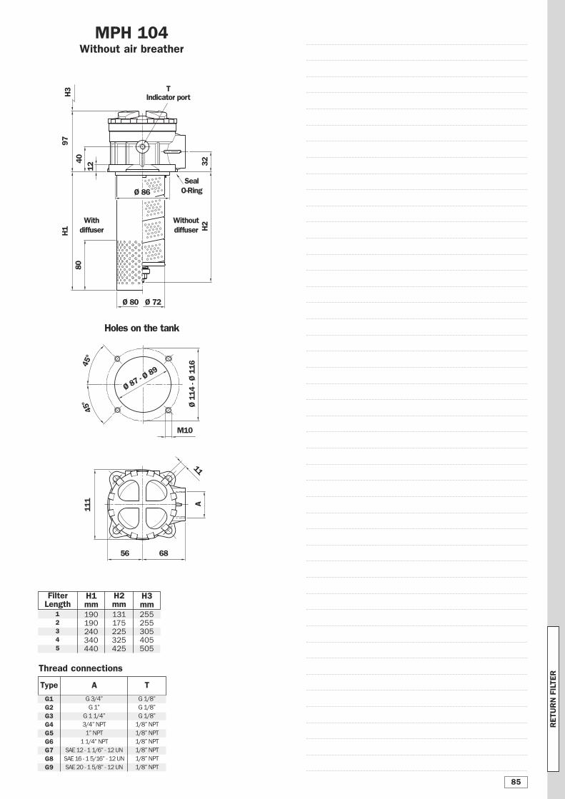
MPH 104Without air breather
M10
Ø 114
- Ø 116
Ø 87 -
Ø 89
45°
45°
Thread connections
A
G1G2G3G4G5G6G7G8G9
G 3/4”
G 1”
G 1 1/4”
3/4” NPT
1” NPT
1 1/4” NPT
SAE 12 - 1 1/6” - 12 UN
SAE 16 - 1 5/16” - 12 UN
SAE 20 - 1 5/8” - 12 UN
FilterLength
H1mm
H2mm
T
G 1/8”
G 1/8”
G 1/8”
1/8” NPT
1/8” NPT
1/8” NPT
1/8” NPT
1/8” NPT
1/8” NPT
H3mm
Ø 80 Ø 72
SealO-Ring
111
11
Withdiffuser
Withoutdiffuser
12345
190190240340440
131175225325425
255255305405505
TIndicator port
Type
RETU
RN FILTE
R
85
Ø 80 Ø 72
H1
99H2
H3
80
34
Ø 86
Holes on the tank
123
25
114 - 116
Ø 89 -
Ø 90
M10
B
42
14
Withdiffuser
Withoutdiffuser
42 42
108
75 68
98
141
88
11343
11
A
5555
46
T Indicatorport
Thread connections A
T
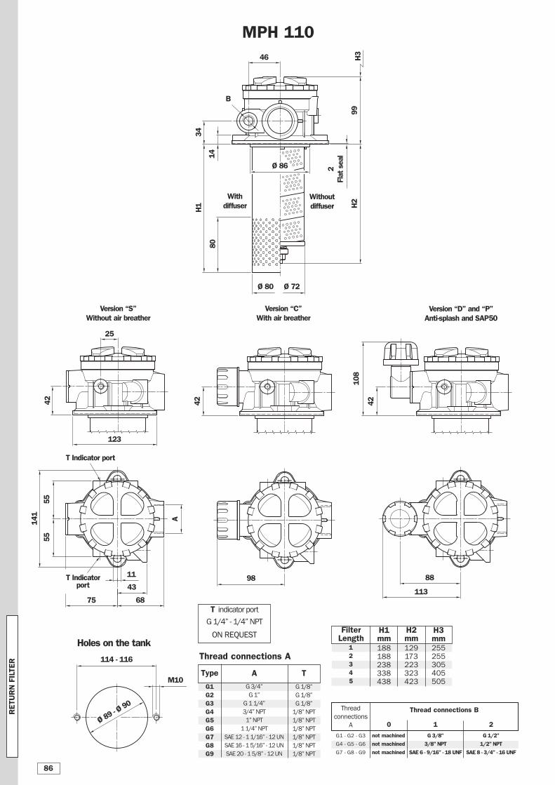
G1G2G3G4G5G6G7G8G9
G 1/8”
G 1/8”
G 1/8”
1/8” NPT
1/8” NPT
1/8” NPT
1/8” NPT
1/8” NPT
1/8” NPT
A
G 3/4”
G 1”
G 1 1/4”
3/4” NPT
1” NPT
1 1/4” NPT
SAE 12 - 1 1/16” - 12 UN
SAE 16 - 1 5/16” - 12 UN
SAE 20 - 1 5/8” - 12 UN
T Indicator port
Version “S”Without air breather
Version “C”With air breather
Version “D” and “P”Anti-splash and SAP50
MPH 110
T indicator port
G 1/4” - 1/4” NPT
ON REQUESTON REQUESTFilterLength
H1mm
H2mm
H3mm
12345
188188238338438
129173223323423
255255305405505
Type
2Flat seal
G1 - G2 - G3
G4 - G5 - G6
G7 - G8 - G9
G 3/8”
3/8” NPT
SAE 6 - 9/16” - 18 UNF
not machined
not machined
not machined
Thread connections B
0 1
Thread
connections
A
G 1/2”
1/2” NPT
SAE 8 - 3/4” - 16 UNF
2
RETU
RN FILTE
R
86
Ø 80 Ø 72
H1
99H2
H3
80
Ø 86
123
42
14
Withdiffuser
Withoutdiffuser
42 42
108
75 68 98
Ø 114
88
113
11
A
T Indicatorport
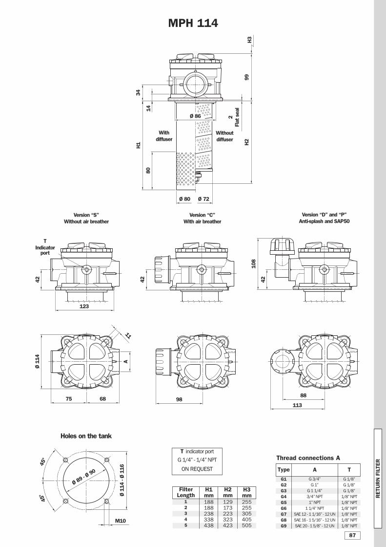
Thread connections A
T
G1G2G3G4G5G6G7G8G9
G 1/8”
G 1/8”
G 1/8”
1/8” NPT
1/8” NPT
1/8” NPT
1/8” NPT
1/8” NPT
1/8” NPT
A
G 3/4”
G 1”
G 1 1/4”
3/4” NPT
1” NPT
1 1/4” NPT
SAE 12 - 1 1/16” - 12 UN
SAE 16 - 1 5/16” - 12 UN
SAE 20 - 1 5/8” - 12 UN
Version “S”Without air breather
Version “C”With air breather
Version “D” and “P”Anti-splash and SAP50
T indicator port
G 1/4” - 1/4” NPT
ON REQUESTON REQUEST
FilterLength
H1mm
H2mm
H3mm
12345
188188238338438
129173223323423
255255305405505
M10
Ø 114
- Ø 116
Ø 89 -
Ø 90
Holes on the tank
45°
45°
MPH 114
Type
2Flat seal
34
RETU
RN FILTE
R
87
Ø 80 Ø 72
H1
99H2
H3
80
34
Ø 86
Holes on the tank
Ø 114
25
114 - 116
Ø 87 -
Ø 89
M10
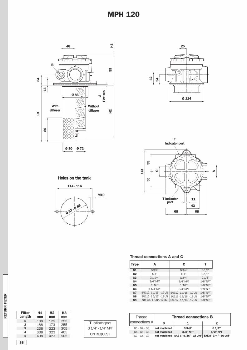
FilterLength
H1mm
H2mm
H3mm
B
42
14
Withdiffuser
Withoutdiffuser
12345
188188238338438
129173223323423
255255305405505
C
46
68 68
141
43
11
A
5555
34
T Indicator port
T Indicatorport
MPH 120
Thread connections A and C
T
G1G2G3G4G5G6G7G8G9
G 1/8”
G 1/8”
G 1/8”
1/8” NPT
1/8” NPT
1/8” NPT
1/8” NPT
1/8” NPT
1/8” NPT
A
G 3/4”
G 1”
G 1 1/4”
3/4” NPT
1” NPT
1 1/4” NPT
SAE 12 - 1 1/16” - 12 UN
SAE 16 - 1 5/16” - 12 UN
SAE 20 - 1 5/8” - 12 UN
C
G 3/4”
G 1”
G 3/4”
3/4” NPT
1” NPT
3/4” NPT
SAE 12 - 1 1/16” - 12 UN
SAE 16 - 1 5/16” - 12 UN
SAE 12 - 1 1/16” - 12 UN
T indicator port
G 1/4” - 1/4” NPT
ON REQUESTON REQUEST
Type
2Flat seal
G1 - G2 - G3
G4 - G5 - G6
G7 - G8 - G9
G 3/8”3/8” NPT
SAE 6 - 9/16” - 18 UNF
not machinednot machinednot machined
Thread connections B
0 1
Thread
connections A
G 1/2”1/2” NPT
SAE 8 - 3/4” - 16 UNF
2
RETU
RN FILTE
R
88
Holes on the tank
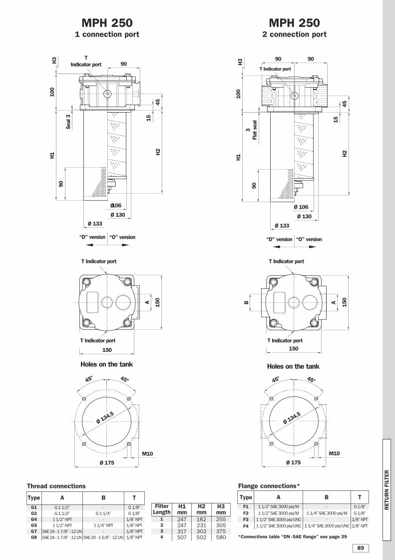
MPH 2501 connection port
90
Ø 133
H1
15
45H2
90
100
Ø 130
Ø 106
15015
0
A
“D” version “O” version
Ø 175
M10
Ø 134,
5
45°45°
Holes on the tank
MPH 2502 connection port
90
Ø 133
H1
15
45H2
H3
90
100
Ø 130
Ø 106
150
150A
“D” version “O” version
Ø 175
M10
Ø 134,
5
45°45°
Thread connections
FilterLength
1234
H1mm
H2mm
247247317507
182231302502
H3mm255305375580
Flange connections*
A B T
G 1/8”
G 1/8”
1/8” NPT
1/8” NPT
1 1/2” SAE 3000 psi/M
1 1/2” SAE 3000 psi/M
1 1/2” SAE 3000 psi/UNC
1 1/2” SAE 3000 psi/UNC
F1
F2F3
F4
-
1 1/4” SAE 3000 psi/M
-
1 1/4” SAE 3000 psi/UNC
90
B T
G1G2G4G5G7G8
A
G 1 1/2”
G 1 1/2”
1 1/2” NPT
1 1/2” NPT
SAE 24 - 1 7/8” - 12 UN
SAE 24 - 1 7/8” - 12 UN
-
G 1 1/4”
-
1 1/4” NPT
-
SAE 20 - 1 5/8” - 12 UN
G 1/8”
G 1/8”
1/8” NPT
1/8” NPT
1/8” NPT
1/8” NPT
T Indicator port
T Indicator port
T Indicator port
T Indicator port
T Indicator port
T Indicator port
*Connections table “DN -SAE flange” see page 39
BH3
Seal 3
Type Type
3Flat seal
RETU
RN FILTE
R
89
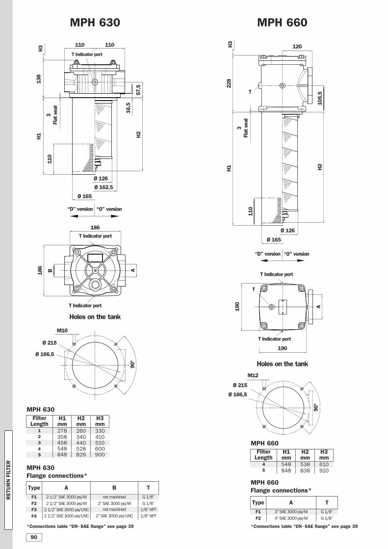
MPH 660
Ø 165
M12
Ø 126
H2
105,5
110
190
A
H1
120
228
Ø 166,5
Ø 215
Holes on the tank
MPH 630
“D” version “O” version
MPH 630FilterLength
12345
H1mm
H2mm
H3mm
260
340440528829
330
410510600900
Holes on the tank
110110
Ø 165
H1
16,5
57,5
H2
H3
110
138
Ø 162,5
Ø 126
186
A186
B
“D” version “O” version
Ø 215
Ø 166,5
M10
190
MPH 630Flange connections*
A B T
G 1/8”
G 1/8”
1/8” NPT
1/8” NPT
278
358458548848
MPH 660FilterLength
45
H1mm
H2mm
H3mm
538
838
548
848
2 1/2” SAE 3000 psi/M
2 1/2” SAE 3000 psi/M
2 1/2” SAE 3000 psi/UNC
2 1/2” SAE 3000 psi/UNC
F1
F2F3
F4
not machined
2” SAE 3000 psi/M
not machined
2” SAE 3000 psi/UNC
MPH 660Flange connections*
90°
90°
A T
F1
F2
3” SAE 3000 psi/M
4” SAE 3000 psi/M
G 1/8”
G 1/8”
T Indicator port
T Indicator port
T Indicator port
H3
T Indicator port
*Connections table “DN -SAE flange” see page 39*Connections table “DN -SAE flange” see page 39
610
910
T
T Indicator port
T
Type
Type
3Flat seal
3Flat seal
RETU
RN FILTE
R
90
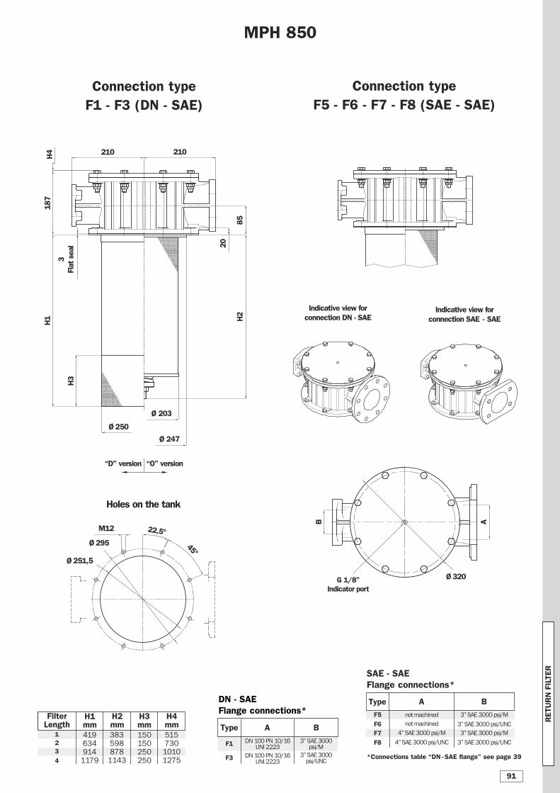
Indicative view for connection DN - SAE
Indicative view for connection SAE - SAE
Connection typeF1 - F3 (DN - SAE)
210 210
Ø 203
Ø 247
H3
H1
85
20
H2
Ø 250
187
Ø 320
AB
M12
Ø295
Ø251,5
45°
MPH 850
22,5°
Holes on the tank
FilterLength
123
4
H1mm
H2mm
419634914
1179
383598878
1143
H3mm
H4mm
150150250250
DN - SAEFlange connections*
SAE - SAE Flange connections*
A B
F1
F3
DN 100 PN 10/16 UNI 2223
DN 100 PN 10/16 UNI 2223
3” SAE 3000 psi/M
3” SAE 3000 psi/UNC
A B
F5
F6F7
F8
not machined
not machined
4” SAE 3000 psi/M
4” SAE 3000 psi/UNC
3” SAE 3000 psi/M
3” SAE 3000 psi/UNC
3” SAE 3000 psi/M
3” SAE 3000 psi/UNC
H4
G 1/8” Indicator port
*Connections table “DN -SAE flange” see page 39
Connection typeF5 - F6 - F7 - F8 (SAE - SAE)
“D” version “O” version
Type
Type
3Flat seal
51573010101275
RETU
RN FILTE
R
91
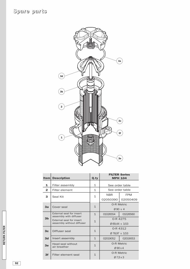
SSppaarree ppaarr ttss
Q.ty
1
1
1
1
1
1
1
1
1
1
Description
Filter assembly
Filter element
Seal Kit
Cover seal
External seal for insert
assembly with diffuser
External seal for insert
assembly without diffuser
Diffuser seal
Insert assembly
Head seal without air breather
Filter element seal
FILTER Series MPH 104
See order table
See order table
NBR FPM
02050390 02050409
O-R Metric
Ø 90 x 4
01026554 01026560
O-R 4275
Ø 69,44 x 3,53
O-R 4312
Ø 78,97 x 3,53
02019052 02019053
O-R Metric
Ø 90 x 4
O-R Metric
Ø 7,5 x 3
3c
3d
1
2
3a
3b
3e
3f
Item
1
2
3
3a
3b
3c
3d
3e
3f
RETU
RN FILTE
R
92
3c
3d
1
2
3a
3b
3e
3f
3g
3g
3i
3h
5
6
4
3h
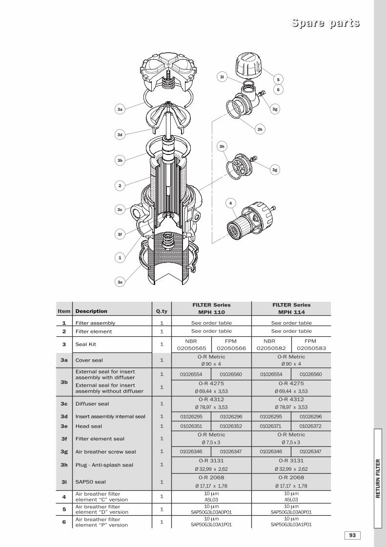
Item
1
2
3
3a
3b
3c
3d
3e
3f
3g
3h
3i
4
5
6
Q.ty
1
1
1
1
1
1
1
1
1
1
1
1
1
1
1
1
Description
Filter assembly
Filter element
Seal Kit
Cover seal
External seal for insert
assembly with diffuser
External seal for insert
assembly without diffuser
Diffuser seal
Insert assembly internal seal
Head seal
Filter element seal
Air breather screw seal
Plug - Anti-splash seal
SAP50 seal
Air breather filter
element “C” version
Air breather filter element “D” version
Air breather filter element “P” version
FILTER Series MPH 110
See order table
See order table
NBR FPM
02050565 02050566
O-R Metric
Ø 90 x 4
01026554 01026560
O-R 4275
Ø 69,44 x 3,53
O-R 4312
Ø 78,97 x 3,53
01026295 01026296
01026351 01026352
O-R Metric
Ø 7,5 x 3
01026346 01026347
O-R 3131
Ø 32,99 x 2,62
O-R 2068
Ø 17,17 x 1,78
10 μm
A5L03
10 μm
SAP50G3L03A0P01
10 μm
SAP50G3L03A1P01
FILTER Series MPH 114
See order table
See order table
NBR FPM
02050582 02050583
O-R Metric
Ø 90 x 4
01026554 01026560
O-R 4275
Ø 69,44 x 3,53
O-R 4312
Ø 78,97 x 3,53
01026295 01026296
01026371 01026372
O-R Metric
Ø 7,5 x 3
01026346 01026347
O-R 3131
Ø 32,99 x 2,62
O-R 2068
Ø 17,17 x 1,78
10 μm
A5L03
10 μm
SAP50G3L03A0P01
10 μm
SAP50G3L03A1P01
SSppaarree ppaarr ttss
RETU
RN FILTE
R
93
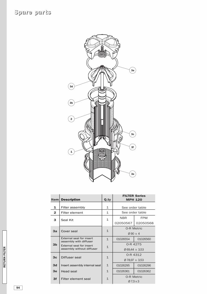
Item
1
2
3
3a
3b
3c
3d
3e
3f
Q.ty
1
1
1
1
1
1
1
1
1
1
Description
Filter assembly
Filter element
Seal Kit
Cover seal
External seal for insert
assembly with diffuser
External seal for insert
assembly without diffuser
Diffuser seal
Insert assembly internal seal
Head seal
Filter element seal
FILTER Series MPH 120
See order table
See order table
NBR FPM
02050567 02050568
O-R Metric
Ø 90 x 4
01026554 01026560
O-R 4275
Ø 69,44 x 3,53
O-R 4312
Ø 78,97 x 3,53
01026295 01026296
01026361 01026362
O-R Metric
Ø 7,5 x 3
3c
3d
1
2
3a
3b
3e
3f
SSppaarree ppaarr ttss
RETU
RN FILTE
R
94
SSppaarree ppaarr ttss
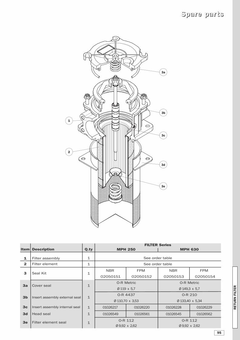
Item
1
2
3
3a
3b
3c
3d
3e
Q.ty
1
1
1
1
1
1
1
1
Description
Filter assembly
Filter element
Seal Kit
Cover seal
Insert assembly external seal
Insert assembly internal seal
Head seal
Filter element seal
FILTER Series MPH 250 MPH 630
See order table
See order table
NBR FPM
02050151 02050152
O-R Metric
Ø 119 x 5,7
O-R 4437
Ø 110,70 x 3,53
01026217 01026220
01026549 01026561
O-R 112
Ø 9,92 x 2,62
3c
3d
1
2
3a
3b
3e
NBR FPM
02050153 02050154
O-R Metric
Ø 149,3 x 5,7
O-R 210
Ø 133,40 x 5,34
01026228 01026229
01026545 01026562
O-R 112
Ø 9,92 x 2,62
RETU
RN FILTE
R
95
SSppaarree ppaarr ttss
3c
3d
1
2
3a
3b
3e
3c
3d
1
2
3a
3b
3e
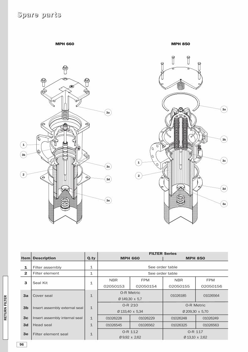
MPH 660 MPH 850
Item
1
2
3
3a
3b
3c
3d
3e
Q.ty
1
1
1
1
1
1
1
1
Description
Filter assembly
Filter element
Seal Kit
Cover seal
Insert assembly external seal
Insert assembly internal seal
Head seal
Filter element seal
FILTER Series MPH 660 MPH 850
See order table
See order table
NBR FPM
02050153 02050154
O-R Metric
Ø 149,30 x 5,7
O-R 210
Ø 133,40 x 5,34
01026228 01026229
01026545 01026562
O-R 112
Ø 9,92 x 2,62
NBR FPM
02050155 02050156
01026185 01026564
O-R Metric
Ø 209,30 x 5,70
01026248 01026249
01026325 01026563
O-R 117
Ø 13,10 x 2,62
RETU
RN FILTE
R
96
MPH1
MR
Filter assembly
Example 1: MPH 104 1 C D S A G1 A25 P01Example 2: MPH 114 3 E D C A G2 M60 P01
Filter element
2 3 4 5
1
Example 1: MR 100 1 A25 A P01Example 2: MR 100 3 M60 A P01
2 8 6b 9
6a 7 8 9
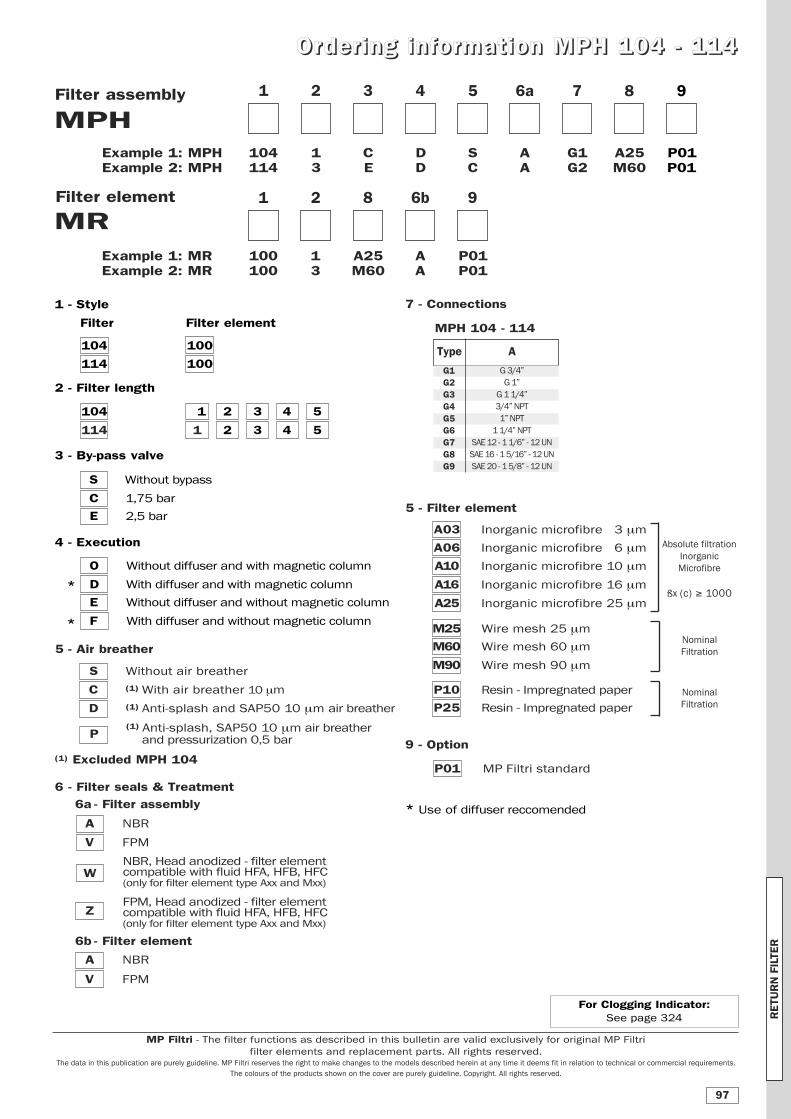
4 - Execution
O Without diffuser and with magnetic column
D With diffuser and with magnetic column
E Without diffuser and without magnetic column
F With diffuser and without magnetic column
9 - Option
P01 MP Filtri standard
7 - Connections
NBR, Head anodized - filter element compatible with fluid HFA, HFB, HFC(only for filter element type Axx and Mxx)
FPM, Head anodized - filter element compatible with fluid HFA, HFB, HFC(only for filter element type Axx and Mxx)
OOrrddeerr iinngg iinn ffoorrmmaatt iioonn MMPPHH 110044 -- 111144
Type A
G1G2G3G4G5G6G7G8G9
G 3/4”
G 1”
G 1 1/4”
3/4” NPT
1” NPT
1 1/4” NPT
SAE 12 - 1 1/6” - 12 UN
SAE 16 - 1 5/16” - 12 UN
SAE 20 - 1 5/8” - 12 UN
1 - Style
Filter Filter element
104 100
114 100
2 - Filter length
104 1 2 3 4 5
114 1 2 3 4 5
3 - By-pass valve
S Without bypass
C 1,75 bar
E 2,5 bar
5 - Air breather
S Without air breather
C (1) With air breather 10 μm
D (1) Anti-splash and SAP50 10 μm air breather
P
(1) Excluded MPH 104
(1) Anti-splash, SAP50 10 μm air breatherand pressurization 0,5 bar
* Use of diffuser reccomended
*
*
MPH 104 - 114
6 - Filter seals & Treatment
6a - Filter assembly
A NBR
V FPM
W
Z
6b - Filter element
A NBR
V FPM
Nominal
Filtration
Absolute filtration
Inorganic
Microfibre
ßx (c) ≥ 1000
5 - Filter element
A03 Inorganic microfibre 3 μm
A06 Inorganic microfibre 6 μm
A10 Inorganic microfibre 10 μm
A16 Inorganic microfibre 16 μm
A25 Inorganic microfibre 25 μm
M25 Wire mesh 25 μm
M60 Wire mesh 60 μm
M90 Wire mesh 90 μm
Nominal
Filtration
P10 Resin - Impregnated paper
P25 Resin - Impregnated paper
RETU
RN FILTE
R
97
MP Filtri - The filter functions as described in this bulletin are valid exclusively for original MP Filtri
filter elements and replacement parts. All rights reserved.The data in this publication are purely guideline. MP Filtri reserves the right to make changes to the models described herein at any time it deems fit in relation to technical or commercial requirements.
The colours of the products shown on the cover are purely guideline. Copyright. All rights reserved.
For Clogging Indicator: See page 324
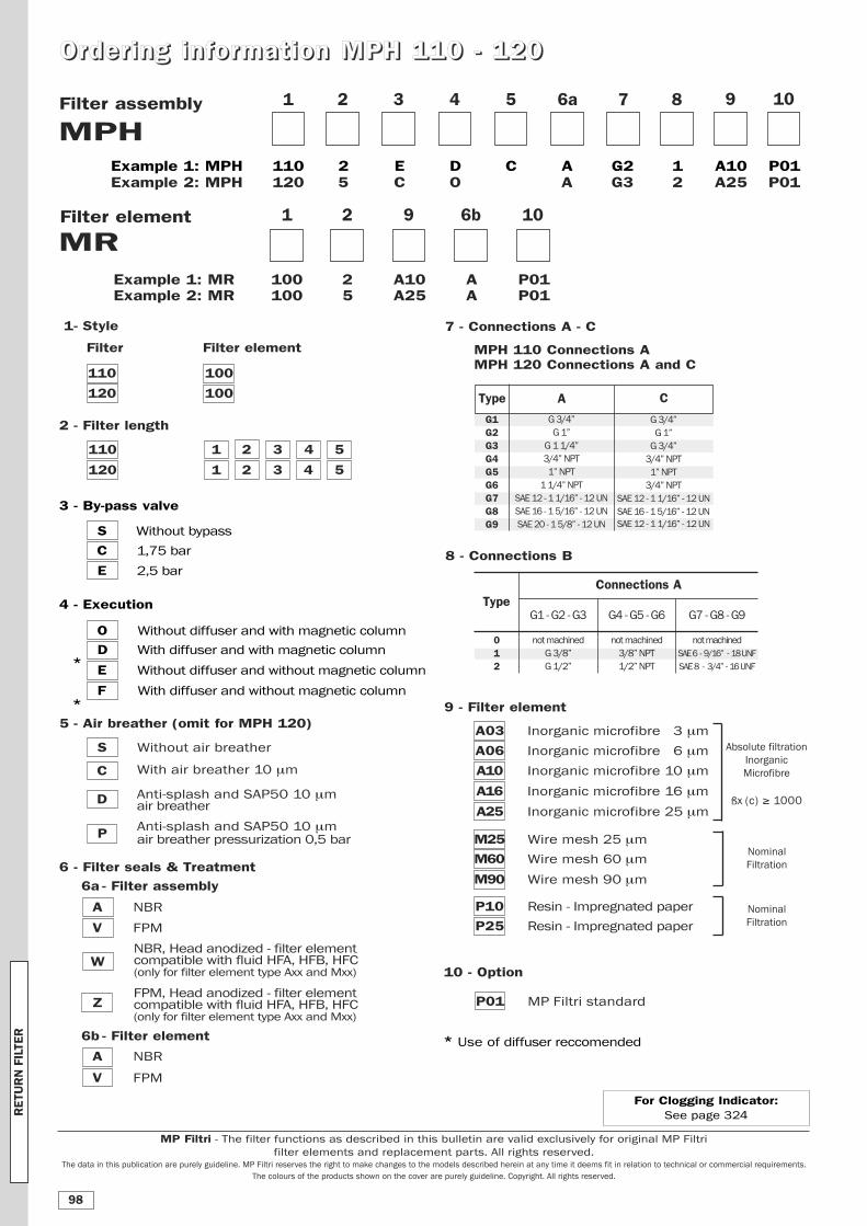
OOrrddeerr iinngg iinn ffoorrmmaatt iioonn MMPPHH 111100 -- 112200
MPH1 2 3 4 5 6a
1 2 9 6b
MR
Filter assembly
Example 1: MPH 110 2 E D C A G2 1 A10 P01Example 2: MPH 120 5 C O A G3 2 A25 P01
Example 1: MR 100 2 A10 A P01Example 2: MR 100 5 A25 A P01
Filter element
7 8
10
10 - Option
P01 MP Filtri standard
7 - Connections A - C
MPH 110 Connections AMPH 120 Connections A and C
8 - Connections B
9
3 - By-pass valve
S Without bypass
C 1,75 bar
E 2,5 bar
4 - Execution
O Without diffuser and with magnetic column
D With diffuser and with magnetic column
E Without diffuser and without magnetic column
F With diffuser and without magnetic column
With air breather 10 μm
Anti-splash and SAP50 10 μmair breather
Anti-splash and SAP50 10 μmair breather pressurization 0,5 bar
5 - Air breather (omit for MPH 120)
S Without air breather
C
D
P
10
Type
012
not machined
G 3/8”
G 1/2”
G1 - G2 - G3
Connections A
not machined
3/8” NPT
1/2” NPT
G4 - G5 - G6
not machined
SAE 6 - 9/16” - 18 UNF
SAE 8 - 3/4” - 16 UNF
G7 - G8 - G9
G1G2G3G4G5G6G7G8G9
A
G 3/4”
G 1”
G 1 1/4”
3/4” NPT
1” NPT
1 1/4” NPT
SAE 12 - 1 1/16” - 12 UN
SAE 16 - 1 5/16” - 12 UN
SAE 20 - 1 5/8” - 12 UN
C
G 3/4”
G 1”
G 3/4”
3/4” NPT
1” NPT
3/4” NPT
SAE 12 - 1 1/16” - 12 UN
SAE 16 - 1 5/16” - 12 UN
SAE 12 - 1 1/16” - 12 UN
Type
2 - Filter length
110 1 2 3 4 5
120 1 2 3 4 5
1 - Style
Filter Filter element
110 100
120 100
* Use of diffuser reccomended
*
*
NBR, Head anodized - filter element compatible with fluid HFA, HFB, HFC(only for filter element type Axx and Mxx)
FPM, Head anodized - filter element compatible with fluid HFA, HFB, HFC(only for filter element type Axx and Mxx)
6 - Filter seals & Treatment
6a - Filter assembly
A NBR
V FPM
W
Z
6b - Filter element
A NBR
V FPM
Nominal
Filtration
Absolute filtration
Inorganic
Microfibre
ßx (c) ≥ 1000
9 - Filter element
A03 Inorganic microfibre 3 μm
A06 Inorganic microfibre 6 μm
A10 Inorganic microfibre 10 μm
A16 Inorganic microfibre 16 μm
A25 Inorganic microfibre 25 μm
M25 Wire mesh 25 μm
M60 Wire mesh 60 μm
M90 Wire mesh 90 μm
Nominal
Filtration
P10 Resin - Impregnated paper
P25 Resin - Impregnated paper
RETU
RN FILTE
R
98
MP Filtri - The filter functions as described in this bulletin are valid exclusively for original MP Filtri
filter elements and replacement parts. All rights reserved.The data in this publication are purely guideline. MP Filtri reserves the right to make changes to the models described herein at any time it deems fit in relation to technical or commercial requirements.
The colours of the products shown on the cover are purely guideline. Copyright. All rights reserved.
For Clogging Indicator: See page 324
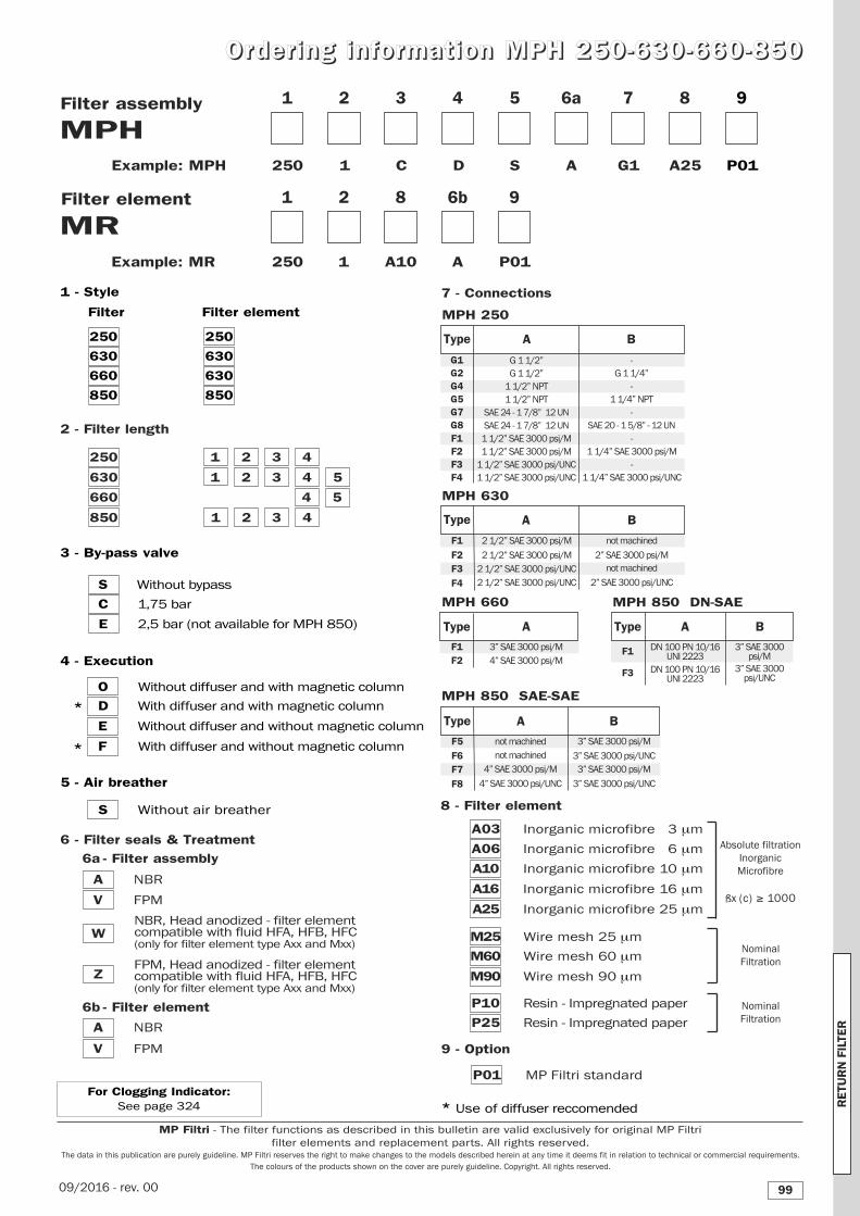
MPH1
MR
Filter assembly
Example: MPH 250 1 C D S A G1 A25 P01
Filter element
2 3 4 5
1
Example: MR 250 1 A10 A P01
2 8 6b 9
6a 7 8 9
5 - Air breather
S Without air breather
9 - Option
P01 MP Filtri standard
7 - Connections
OOrrddeerr iinngg iinn ffoorrmmaatt iioonn MMPPHH 225500--663300--666600--885500
3 - By-pass valve
S Without bypass
C 1,75 bar
E 2,5 bar (not available for MPH 850)
1 1/2” SAE 3000 psi/M
1 1/2” SAE 3000 psi/M
1 1/2” SAE 3000 psi/UNC
1 1/2” SAE 3000 psi/UNC
F1F2F3F4
-
1 1/4” SAE 3000 psi/M
-
1 1/4” SAE 3000 psi/UNC
B
G1G2G4G5G7G8
A
G 1 1/2”
G 1 1/2”
1 1/2” NPT
1 1/2” NPT
SAE 24 - 1 7/8” 12 UN
SAE 24 - 1 7/8” 12 UN
-
G 1 1/4”
-
1 1/4” NPT
-
SAE 20 - 1 5/8” - 12 UN
Type A B
2 1/2” SAE 3000 psi/M
2 1/2” SAE 3000 psi/M
2 1/2” SAE 3000 psi/UNC
2 1/2” SAE 3000 psi/UNC
F1
F2F3
F4
not machined
2” SAE 3000 psi/M
not machined
2” SAE 3000 psi/UNC
A
F1F2
3” SAE 3000 psi/M
4” SAE 3000 psi/M
A B
F1
F3
DN 100 PN 10/16 UNI 2223
DN 100 PN 10/16 UNI 2223
3” SAE 3000 psi/M
3” SAE 3000 psi/UNC
A B
F5
F6F7
F8
not machined
not machined
4” SAE 3000 psi/M
4” SAE 3000 psi/UNC
3” SAE 3000 psi/M
3” SAE 3000 psi/UNC
3” SAE 3000 psi/M
3” SAE 3000 psi/UNC
Type
MPH 250
MPH 630
MPH 660
Type Type
MPH 850 DN-SAE
MPH 850 SAE-SAE
Type
4 - Execution
O Without diffuser and with magnetic column
D With diffuser and with magnetic column
E Without diffuser and without magnetic column
F With diffuser and without magnetic column
1 - Style
Filter Filter element
250 250
630 630
660 630
850 850
2 - Filter length
250 1 2 3 4
630 1 2 3 4 5
660 4 5
850 1 2 3 4
* Use of diffuser reccomended
*
*
NBR, Head anodized - filter element compatible with fluid HFA, HFB, HFC(only for filter element type Axx and Mxx)
FPM, Head anodized - filter element compatible with fluid HFA, HFB, HFC(only for filter element type Axx and Mxx)
6 - Filter seals & Treatment
6a - Filter assembly
A NBR
V FPM
W
Z
6b - Filter element
A NBR
V FPM
Nominal
Filtration
Absolute filtration
Inorganic
Microfibre
ßx (c) ≥ 1000
8 - Filter element
A03 Inorganic microfibre 3 μm
A06 Inorganic microfibre 6 μm
A10 Inorganic microfibre 10 μm
A16 Inorganic microfibre 16 μm
A25 Inorganic microfibre 25 μm
M25 Wire mesh 25 μm
M60 Wire mesh 60 μm
M90 Wire mesh 90 μm
Nominal
Filtration
P10 Resin - Impregnated paper
P25 Resin - Impregnated paper
RETU
RN FILTE
R
99
MP Filtri - The filter functions as described in this bulletin are valid exclusively for original MP Filtri
filter elements and replacement parts. All rights reserved.The data in this publication are purely guideline. MP Filtri reserves the right to make changes to the models described herein at any time it deems fit in relation to technical or commercial requirements.
The colours of the products shown on the cover are purely guideline. Copyright. All rights reserved.
For Clogging Indicator: See page 324
09/2016 - rev. 00
Related Documents