Cast Steel Valves

Welcome message from author
This document is posted to help you gain knowledge. Please leave a comment to let me know what you think about it! Share it to your friends and learn new things together.
Transcript
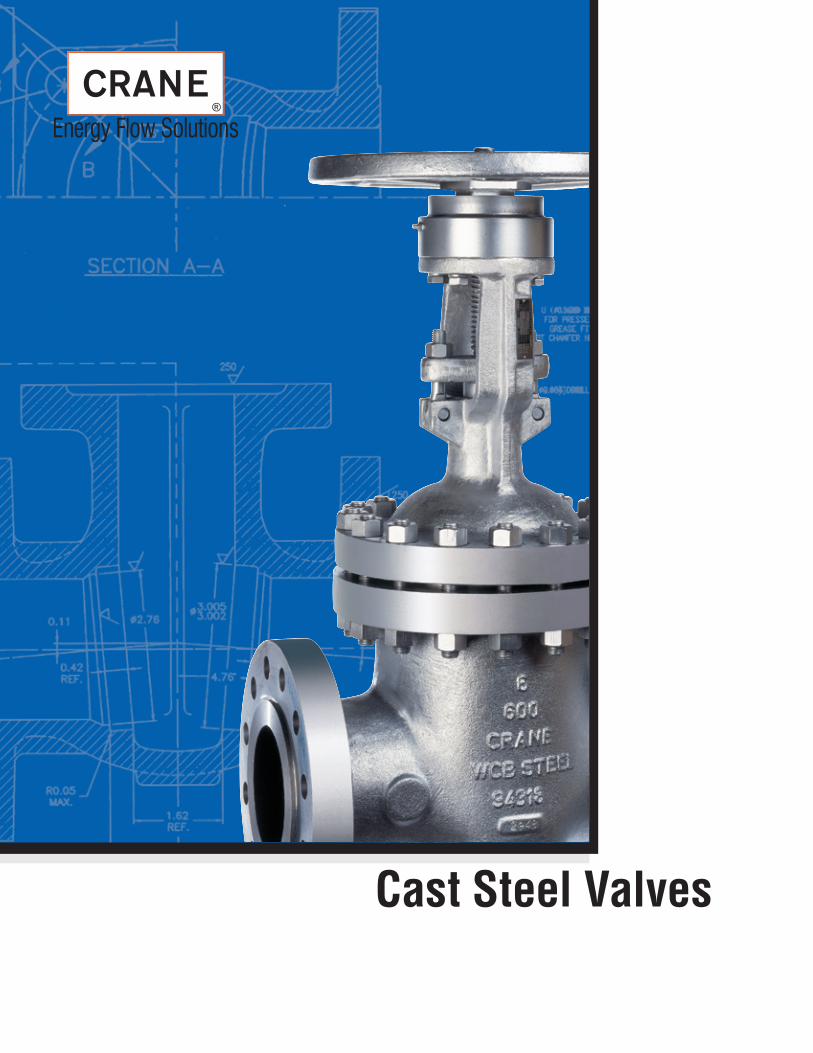
Cast Steel Valves


-�-
Cast Steel Valves
Ordering Information .................................................................................................................... 2General Data ................................................................................................................................ 3Materials ....................................................................................................................................... 4Identification ................................................................................................................................. 5General Features ......................................................................................................................... 6Gate Valve Features ..................................................................................................................... 7NACE Trim Steel Valves ..............................................................................................................��Globe Valve Features ............................................................................................................�2–�3Swing Check Valve Features ................................................................................................ �7–�8Tilting Disc Valve Features................................................................................................... 22–23Stop Check Valve Features ........................................................................................................ 29Stop Check Valve Technical Data .............................................................................................. 32Flow Data ................................................................................................................................... 33Installation Recommendations ................................................................................................... 34Pressure/Temperature Ratings ............................................................................................ 35–37
Crane Valve also manufactures bronze ball valves, iron wafer and lug butterfly valves, bronze and iron gate globe and check valves, and alloy valves. Brochures and catalogs are available on request.
General Index
Figure Number Index
FIGURE NO. VALVE TYPE PRESSURE CLASS CONNECTIONS SIZE RANGE PAGE NO.
28 Stop Check Valve 300 Flanged 3" – �0" 30 28½ Butt-Weld 30 Stop Check Valve 300 Flanged 3" – �0" 3� 30½ Butt-Weld 33 Gate Valve 300 Flanged 2" – 24" 9 33½ Butt-Weld 47 Gate Valve �50 Flanged 2" – 24" 8 47½ Butt-Weld 76 Gate Valve 600 Flanged 2" – 24" �0 76½ Butt-Weld �23 Tilting Disc Valve �50 Flanged 2" – 36" 24 �23½ Butt-Weld �43 Globe Valve �50 Flanged 2" – �4" �4 �43½ Butt-Weld �47 Swing Check Valve �50 Flanged 2" – 24" �9 �47½ Butt-Weld �5� Globe Valve 300 Flanged 2" – �2" �5 �5�½ Butt-Weld �59 Swing Check Valve 300 Flanged 2" – 24" 20 �59½ Butt-Weld �7� Globe Valve 600 Flanged 2" – 8" �6 �7�½ Butt-Weld �75 Swing Check Valve 600 Flanged 2" – 8" 2� �75½ Butt-Weld 323 Tilting Disc Check 300 Flanged 2" – 36" 25 323½ Butt-Weld 623 Tilting Disc Check 600 Flanged 2" – 30" 26 623½ Butt-Weld 923 Tilting Disc Check 900 Flanged 2" – �8" 27 923½ Butt-Weld �523 Tilting Disc Check �500 Flanged 2" – �0" 28 �523½ Butt-Weld

-2-
Cast Steel Valves
How to Specify and Order the Correct Valves
Care should be taken to select the most suitable steel valve for your service(s). Exact specification of each valve should be made to avoid ambiguity when requesting quotations or ordering the product.
SizeNominal size of the pipeline into which the valve will be placed must be determined. Comprehensive data on flow characteristic and pipe properties are contained in the Engineering Data Catalog.
Valve MaterialThe following facts should be considered in determining the correct valve material.• The media to be controlled.• The temperature of the media.• The possible extraordinary stresses affecting the valve.• Safety standards and/or piping codes.
Type of ValveA few minutes spent in reading some simple valve facts on pages 3 and 4 will prove helpful.
Pressure/Temperature RatingPlease pay careful attention that the PRESSURE/TEMPERATURE RATINGS shown on page 32 in this catalog are in keeping with the requirements of the service.
Valve End ConnectionsConsiderations as to pipeline integrity, future maintenance, corrosion factors, field assembly, weight and safety should be given in determining the method of connecting the valve in the pipeline.
CAUTION: When servicing, disassembling or disposing of valves containing asbestos gaskets or packing, avoid breathing dust or fibers from these parts. Disposal of asbestos and asbestos related products should comply with local, state and federal laws and regulations.
Designate the valve size and the complete catalog number, including prefix and suffix letters, when applicable, to identify regular cataloged items as described on the following pages.
Ordering Information
Examples
Any special requirements such as Gear operation, Motor operation, Hydraulic or Pneumatic Cylinder operation, Anti-friction bearing yoke sleeve, By-Pass of drain, etc. must also be specified on purchase orders.
8" 33½ XU F 9 BP
Suffix denoting basic valve material – Page 4
Suffix denoting flexible disc
Suffix denoting trim material – Page 4
Basic catalog number defined on data pages
Valve size
Suffix denoting basic valve material – Page 4
NOTE: In keeping with our policy of continuous product improvement, we reserve the right to institute changes in design, material, dimensions, and specifications without notice and without incurring any obligation to make such changes and modifications on the product previously or subsequently sold.
-3-
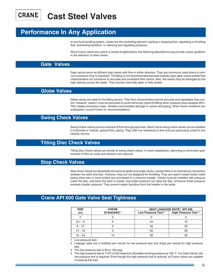
In any fluid handling system, valves are the controlling element: starting or stopping flow, regulating or throttling flow, preventing backflow, or relieving and regulating pressure.
Since Crane valves are used in a variety of applications, the following descriptions may provide a basic guideline in the selection of steel valves.
Gate Valves
Globe Valves
Swing Check Valves
Tilting Disc Check Valves
Performance In Any Application
Cast Steel Valves
Gate valves serve as efficient stop valves with flow in either direction. They are commonly used where a mini-mum pressure drop is important. Throttling is not recommended because partially open gate valves exhibit flow characteristics not conducive to accurate and consistent flow control. Also, the valves may be damaged by the high velocity across the seats. They function best fully open or fully closed.
Globe valves are ideal for throttling service. Their flow characteristics permit accurate and repeatable flow con-trol. However, caution must be exercised to avoid extremely close throttling when pressure drop exceeds 20%. This creates excessive noise, vibration and possible damage to valves and piping. When these conditions are anticipated, consult Crane for recommendations.
Swing Check valves prevent reversal of flow through pipe lines. Most Crane swing check valves can be installed in horizontal or vertical, upward flow, piping. They offer low resistance to flow and are particularly suited to low velocity service.
Stop Check Valves
Tilting Disc Check valves are similar to swing check valves. In most installations, slamming is minimized upon reversal of flow so noise and vibration are reduced.
Stop check valves are essentially the same as globe and angle valves, except there is no mechanical connection between the stem and disc. However, they are not designed for throttling. They are used in steam boiler outlet piping when two or more boilers are connected to a common header. Valves must be installed with pressure under the disc, and when the stem is raised, only boiler pressure can raise the disc, whenever boiler pressure exceeds header pressure. They prevent steam backflow from the header to the boiler.
Crane API 600 Gate Valve Seat Tightness
SIZE CRANE SEAT LEAKAGE RATE(2) API 598 (in) STANDARD(�) Low Pressure Test(3) High Pressure Test (4)
2 0 0 0
2½ – 6 0 24 �2
8 – �2 0 40 20
�4 – �6 0 56 28
�8 – 24 �4 56 28
� Low pressure test.2 Leakage rates are in bubbles per minute for low pressure test and drops per minute for high pressure
test.3 The low pressure test is 60 to �00 psig.4 The high pressure test is ��0% of the maximum allowable working pressure at �00° F. For Gate Valves, the
low pressure test is required. Even though the high pressure test is optional, all Crane valves are capable of passing this test.

-4-
Cast Steel Valves
Materials of ConstructionSteel bolted bonnet valves described in this catalog are typically manufactured of carbon steel. When specified, the valves are available in the alloys shown below which are suitable for steam, water, oil, oil vapor, gas and general services. Please contact factory or customer service for availability and material breakdowns.
Body and Bonnet or Cap Materials
Part No. ASTM Material Service Suffix Classification Classification Conditions
None A2�6 WCB Carbon Steel For service up to �000° F where corrosion and oxidation are not a factor. (�) (4) (5)
6 A2�7 WC6 � ¼ CR, ½ Mo For service up to �000° F. (3) (4) (5)
9 A2�7 WC9 2 ¼ CR, � Mo For service up to ��00° F where good creep strength is required. (3) (4) (5)
5 A2�7 C5 5% CR, ½ Mo For service up to �200° F. Best corrosion and oxidation resistance plus high creep strength are required.
�2 A2�7 C�2 9% CR, � Mo For service up to �200° F. Best corrosion and oxidation resistance than other grades.
2 A35� LCC Low Carbon Steel For service from –50° F to 650° F. This material must be quenched and tempered to obtain tensile and impact properties needed at sub-zero temperatures.
(�) Upon prolonged exposure to temperatures above 800° F, the carbide phase of carbon steel may be converted to graphite. Permissible, but not recommended for prolonged usage above 800°F.(2) Valve regularly rated to �000° F.(3) Considerations should be given to the possibility of excessive oxidation (scaling) when used above �050° F.
(4) Product used within the jurisdiction of Section � Power Boilers of the ASME Boiler and Pressure Vessel code is subject to the same temperature limitations as specified in that document.(5) Product used within the jurisdiction of Power Piping, ASME Code for Pressure Piping B3�.�, is subject to the same maximum temperature limitations placed upon the material in paragraph �24.2.
Trim Material Part No. API Trim Suffix Number Nominal Trim Seating Surfaces Stem Material Temperature
X � F6 / F6 (�) �3 Cr ASTM A2�7 (CA�5) �3 Cr (4�0) ��00° F
UF* 5 HF / HF (2) Stellite 6 �3 Cr (4�0) �200° F
A 9 Monel / Monel (4) Monel Monel 450° F
L �0 3�6 / 3�6 (3) 3�6 SS 3�6 SS 850° F
XUF* 8 F6 / HF (�) (2) �3 Cr ASTM A2�7 (CA 2�5) �3 Cr (4�0) ��00° F Stellite 6
AUF* �� Monel / HF (4) (2) Monel Monel 450° F Stellite 6
LUF* �2 3�6 / HF (3) (2) 3�6 SS 3�6 SS 850° F Stellite 6
(�) �3% Chromium AISI Type 4�0 Stainless Steel.(2) Hard Facing is weld deposited Cobalt base alloy.
(3) Austenitic Stainless Steel is a Ni-Cr-Mo stainless steel in the AISI Type 3�6 category.(4) Ni-Cu Alloy.
Valve Modification Suffix Identification
S.I. Description TD Drain, Drill, and Tap
BP Bypass
PG Special Packing and/or Gasket
S.I. Description ST Special Trim
BW Special Butt-Weld End Prep
RJ Ring Joint
S.I. Description SP Special Paint
LD Locking Device
LR Lantern Ring
S.I. Description OV (�) Gear (4) Pneumatic
(2) Chainwheel (5) Hydraulic
(3) Electric (6) Other
*F denotes Flex Wedge (only applies to Gate Valves).
-5-
Installation, Marking, and Identification
When purchasing valves, reference should also be made to MSS 6683 “Guide to the Installation and Use of Valves.” Inquires relating specifically to Crane products may be referred to our factory or customer service department.
Marking and identification of Crane steel valves conforms to ASME B�6.34 and MSS SP-25.
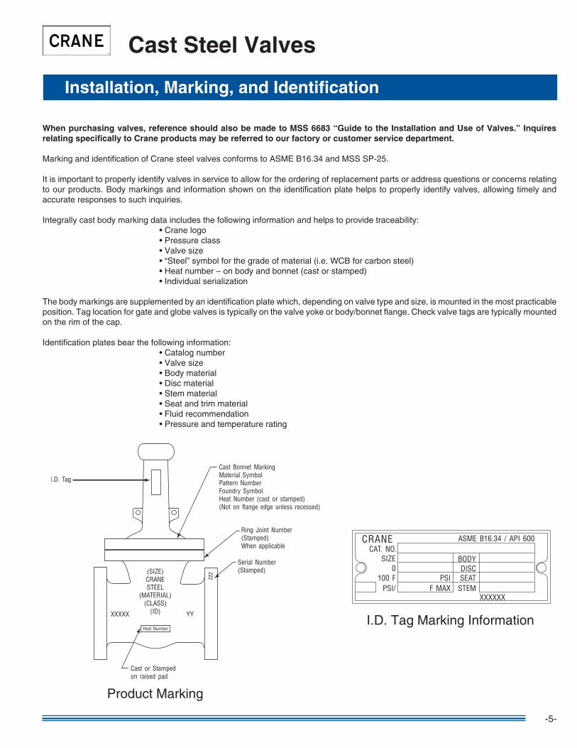
It is important to properly identify valves in service to allow for the ordering of replacement parts or address questions or concerns relating to our products. Body markings and information shown on the identification plate helps to properly identify valves, allowing timely and accurate responses to such inquiries.
Integrally cast body marking data includes the following information and helps to provide traceability: • Crane logo • Pressure class • Valve size • “Steel” symbol for the grade of material (i.e. WCB for carbon steel) • Heat number – on body and bonnet (cast or stamped) • Individual serialization
The body markings are supplemented by an identification plate which, depending on valve type and size, is mounted in the most practicable position. Tag location for gate and globe valves is typically on the valve yoke or body/bonnet flange. Check valve tags are typically mounted on the rim of the cap.
Identification plates bear the following information: • Catalog number • Valve size • Body material • Disc material • Stem material • Seat and trim material • Fluid recommendation • Pressure and temperature rating
Cast Steel Valves
CRANECAT. NO.
SIZE0
100 FPSI/ F MAX
PSISTEM
DISCBODY
ASME B16.34 / API 600
XXXXXX
SEAT
Product Marking
I.D. Tag Marking Information

-6-
These valves comply with the applicable requirements of the following standards:
• API 600 • API 598 • API RP59� • ASME B�6.34 • ASME B�6.25 • ASME B�6.�0 • ASME B�6.5
Cast Steel Gate Valves
General Information • Class 150, 300, and 600 Valves
• Standard material is ASTM A2�6 Grade WCB. • Standard trim is XU (�3% Cr to hardface) which is suitable for a wide range of applications. • See Engineering Data section for end flange dimensions and drilling templates. • Butt weld ends on valves 24" and smaller are bored to match standard pipe unless otherwise specified. See Engineering Data catalog for details. • See Engineering Data section for locations of by-passes, taps, and drains.
Features
Standards
Notes
Flexible Wedge • Compensates for deformation of body due to pipe stresses. • Will not stick when valve is closed hot and allowed to cool.
Welded-in Seat Ring • Seat ring is seal welded to eliminate leak path.
Fugitive Emissions • Less than �00 ppm with standard requirements.
Every Crane cast steel valve is subjected to a �00% pressure test according to API 598 requirements. Manufacturer’s material test reports and Inspection and Test Certifications are available upon request. Some of the additional inspections and tests performed are:
• Random Radiograph Inspection of Body and Bonnet Castings to ASME B�6.34 Appendix B • Random Chemical Composition and Mechanical Properties Verification of Fasteners to ASTM A-�93/A-�94 • Liquid Penetrate Inspection of Seat Rings • Visual Inspection of Casting to MSS SP-55 • Receiving, In-Process, and Final Dimensional Inspections to Relevant Valve Standards
Other inspections or tests can be performed or evaluation criteria applied when specified by the customer.
Inspection Policy for Crane Valves
-7-
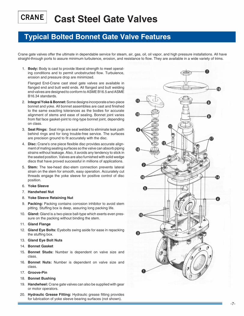
�. Body: Body is cast to provide liberal strength to meet operat-ing conditions and to permit unobstructed flow. Turbulence, erosion and pressure drop are minimized.
Flanged End-Crane cast steel gate valves are available in flanged end and butt weld ends. All flanged and butt welding end valves are designed to conform to ASME B�6.5 and ASME B�6.34 standards.
2. Integral Yoke & Bonnet: Some designs incorporate a two-piece bonnet and yoke. All bonnet assemblies are cast and finished to the same exacting tolerances as the bodies for accurate alignment of stems and ease of sealing. Bonnet joint varies from flat face gasket-joint to ring-type bonnet joint, depending on class.
3. Seat Rings: Seat rings are seal welded to eliminate leak path behind rings and for long trouble-free service. The surfaces are precision ground to fit accurately with the disc.
4. Disc: Crane's one piece flexible disc provides accurate align-ment of mating seating surfaces so the valve can absorb piping strains without leakage. Also, it avoids any tendency to stick in the seated position. Valves are also furnished with solid wedge discs that have proved successful in millions of applications.
5. Stem: The tee-head disc-stem connection prevents lateral strain on the stem for smooth, easy operation. Accurately cut threads engage the yoke sleeve for positive control of disc position.
6. Yoke Sleeve
7. Handwheel Nut
8. Yoke Sleeve Retaining Nut
9. Packing: Packing contains corrosion inhibitor to avoid stem pitting. Stuffing box is deep, assuring long packing life.
�0. Gland: Gland is a two-piece ball-type which exerts even pres-sure on the packing without binding the stem.
��. Gland Flange
�2. Gland Eye Bolts: Eyebolts swing aside for ease in repacking the stuffing box.
�3. Gland Eye Bolt Nuts
�4. Bonnet Gasket
�5. Bonnet Studs: Number is dependent on valve size and class.
�6. Bonnet Nuts: Number is dependent on valve size and class.
�7. Groove-Pin
�8. Bonnet Bushing
�9. Handwheel: Crane gate valves can also be supplied with gear or motor operators.
20. Hydraulic Grease Fitting: Hydraulic grease fitting provides for lubrication of yoke sleeve bearing surfaces (not shown).
Typical Bolted Bonnet Gate Valve Features
Cast Steel Gate Valves
Crane gate valves offer the ultimate in dependable service for steam, air, gas, oil, oil vapor, and high pressure installations. All have straight-through ports to assure minimum turbulence, erosion, and resistance to flow. They are available in a wide variety of trims.

-8-
Cast Steel Gate Valves
Class 150 • Outside Screw & Yoke • Flexible Wedge Disc
Figure 47Flanged
Figure 47½Butt Weld
Size Range:
2 through 24 inches
Pressure Temperature RatingCarbon SteelASTM A2�6 Grade WCB285 psi @ -20°F to �00°F
Figures 4747½
Material of Construction Description Material Body WCB Bonnet WCB SeatRings Hardfaced Disc CA-15or13%CROverlay Stem 410SS Packing Graphite BonnetGasket SSTangedRef.Flex.Graphite BackSeat 410SS YokeSleeve D2Ni-Resist RetainingNut MalleableorSteel Gland Steel GlandFlange Steel EyeBolt Steel EyeBoltNuts Steel Pins Steel BonnetStuds A193Gr.B7 BonnetNuts A194Gr.2H Handwheel Malleable,Ductile,orSteel HandwheelNut DuctileorSteel I.D.Tags SS I.D.Pins Steel Spacer Steel GreaseFittings Steel
C
B
A
Dimensions and Weights Dimensions (inches) Weight (pounds) A B C 47 47½ 47 47½ Valve Open 2 46 45 7.00 8.50 16.50 8.00 2½ 70 60 7.50 9.50 16.50 8.00 3 76 62 8.00 11.12 19.00 9.00 4 110 95 9.00 12.00 23.00 10.00 5 155 140 10.00 15.00 27.88 12.00 6 175 165 10.50 15.88 31.00 12.00 8 310 260 11.50 16.50 39.00 14.00 10 455 410 13.00 18.00 46.75 16.00 12 650 580 14.00 19.75 55.00 18.00 14 860 730 15.00 22.50 60.50 20.00 16 1120 960 16.00 24.00 66.75 20.00 18 1400 1250 17.00 26.00 77.50 23.62 20 2125 1855 18.00 28.00 84.00 23.62 24 3120 2500 20.00 32.00 101.00 28.35
ValveSize
SteelValves ASMEB16.34
Face-to-Face/End-to-End ASMEB16.10
FlangeDimensions ASMEB16.5
WeldEnd ASMEB.16.25
BasicDesign API600
Testing API598
Acceptance APIRP591
Industry Standards
-9-
Cast Steel Gate Valves
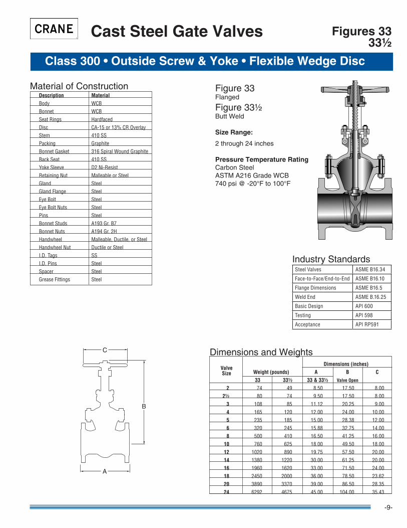
Figure 33Flanged
Figure 33½Butt Weld
Size Range:
2 through 24 inches
Pressure Temperature RatingCarbon SteelASTM A2�6 Grade WCB740 psi @ -20°F to �00°F
Class 300 • Outside Screw & Yoke • Flexible Wedge Disc
Figures 3333½
Material of Construction Description Material Body WCB Bonnet WCB SeatRings Hardfaced Disc CA-15or13%CROverlay Stem 410SS Packing Graphite BonnetGasket 316SpiralWoundGraphite BackSeat 410SS YokeSleeve D2Ni-Resist RetainingNut MalleableorSteel Gland Steel GlandFlange Steel EyeBolt Steel EyeBoltNuts Steel Pins Steel BonnetStuds A193Gr.B7 BonnetNuts A194Gr.2H Handwheel Malleable,Ductile,orSteel HandwheelNut DuctileorSteel I.D.Tags SS I.D.Pins Steel Spacer Steel GreaseFittings Steel
B
A
C
SteelValves ASMEB16.34
Face-to-Face/End-to-End ASMEB16.10
FlangeDimensions ASMEB16.5
WeldEnd ASMEB.16.25
BasicDesign API600
Testing API598
Acceptance APIRP591
Industry Standards
Dimensions and Weights Dimensions (inches) Weight (pounds) A B C 33 33½ 33 & 33½ Valve Open
2 74 49 8.50 17.50 8.00 2½ 80 74 9.50 17.50 8.00 3 108 85 11.12 20.25 9.00 4 165 120 12.00 24.00 10.00 5 235 185 15.00 28.38 12.00 6 320 245 15.88 32.75 14.00 8 500 410 16.50 41.25 16.00 10 760 625 18.00 49.50 18.00 12 1020 890 19.75 57.50 20.00 14 1380 1220 30.00 61.25 20.00 16 1960 1620 33.00 71.50 24.00 18 2450 2000 36.00 78.50 23.62 20 3890 3370 39.00 86.50 28.35 24 6292 4675 45.00 104.00 35.43
ValveSize
-�0-
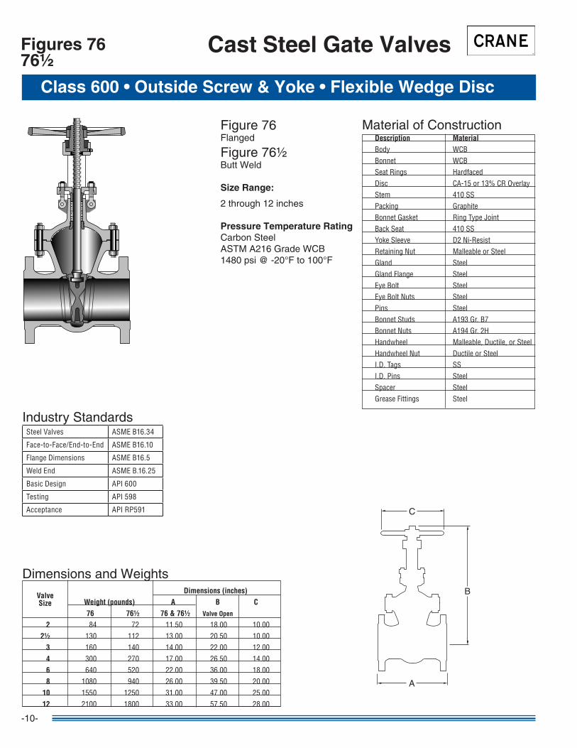
Figure 76Flanged
Figure 76½Butt Weld
Size Range:
2 through �2 inches
Pressure Temperature RatingCarbon SteelASTM A2�6 Grade WCB�480 psi @ -20°F to �00°F
Class 600 • Outside Screw & Yoke • Flexible Wedge Disc
Cast Steel Gate ValvesFigures 7676½
Material of Construction Description Material Body WCB Bonnet WCB SeatRings Hardfaced Disc CA-15or13%CROverlay Stem 410SS Packing Graphite BonnetGasket RingTypeJoint BackSeat 410SS YokeSleeve D2Ni-Resist RetainingNut MalleableorSteel Gland Steel GlandFlange Steel EyeBolt Steel EyeBoltNuts Steel Pins Steel BonnetStuds A193Gr.B7 BonnetNuts A194Gr.2H Handwheel Malleable,Ductile,orSteel HandwheelNut DuctileorSteel I.D.Tags SS I.D.Pins Steel Spacer Steel GreaseFittings Steel
B
A
C
SteelValves ASMEB16.34
Face-to-Face/End-to-End ASMEB16.10
FlangeDimensions ASMEB16.5
WeldEnd ASMEB.16.25
BasicDesign API600
Testing API598
Acceptance APIRP591
Industry Standards
Dimensions and Weights Dimensions (inches) Weight (pounds) A B C 76 76½ 76 & 76½ Valve Open
2 84 72 11.50 18.00 10.00 2½ 130 112 13.00 20.50 10.00 3 160 140 14.00 22.00 12.00 4 300 270 17.00 26.50 14.00 6 640 520 22.00 36.00 18.00 8 1080 940 26.00 39.50 20.00 10 1550 1250 31.00 47.00 25.00 12 2100 1800 33.00 57.50 28.00
ValveSize

-��-
NACE Trim Steel Valves
Specialty Steel Valves
For servicing sour environments of Hydrogen Sulfide (H2S) bearing hydrocarbons, Crane offers NACE valves made of component materials specially heat-treated and hardness-controlled in compliance with NACE standard MR0�75. Typical NACE material configurations are shown below for Crane cast steel gate valves.
NACE Valves Compared to API 600 Valves
Valve Parts API and Hardness LF Trim NACE LUF Trim NACE
Body/Bonnet ASTM A2�6 Grade ASTM A2�6 Grade ASTM A2�6 Grade WCB WCB; ≤22HRC WCB; ≤22HRC
Disc – Solid Metal ASTM A2�7 Grade ASTM A35� Grade ASTM A35� Grade CA�5; 250 min. CF8M; ≤22HRC CF8M; ≤22HRC
Seat Ring Stellite Overlayed; 3�6L Overlayed; Stellite Overlayed; Overlay ≥350 HB Base Metal ≤22 HRC Base Metal ≤22 HRC
Gland Steel Zinc Plated Steel Zinc Plated; Steel Zinc Plated; Base Metal ≤22 HRC Base Metal ≤22 HRC
Stem �3Cr; 200-275 HB ASTM A�82 Grade ASTM A�82 Grade F3�6; ≤22HRC F3�6; ≤22HRC
Backseat Bushing �3Cr; 250 HB min. ASTM 479 Grade ASTM 479 Grade T3�6; ≤22 HRC T3�6; ≤22HRC
Body/Bonnet Studs ASTM A�93 ASTM A�93 ASTM A�93 Grade 2H Grade B7M Grade B7M
Body/Bonnet Nuts ASTM A�94 ASTM A�94 ASTM A�94 Grade 2H Grade 2HM Grade 2HM
A
B
C
D
Body & Bonnet – Most NACE requirements for heat treatment and maximum hardness of 22 HRC. Standard material is ASTM A2�6 Grade WCB.
Bolting – ASTM A�93 Grade B7M bolts and ASTM A�94 Grade 2HM nuts meet both NACE Classes I and II.
Stem – Offering superior resistance to stress corrosion cracking, standard NACE stem is type 3�6 stainless steel in conformance with NACE hardness and heat treatment require-ments.
Disc – Standard disc is one piece flexible wedge ASTM A35� Grade CF8M, type 3�6 stain-less steel in conformance with NACE hardness and heat treatment requirements.

-�2-
Cast Steel Globe Valves
General Information • Class 150, 300, and 600 Valves
Welded-in Seat Ring • Seat ring is seal welded to eliminate leak path.
Fugitive Emissions • Less than �00 ppm with standard requirements.
• Standard material is ASTM A2�6 Grade WCB. • Standard trim is XU (�3% CR to hardface) which is suitable for a wide range of applications. • See “Technical Data” section for end flange dimensions and drilling templates. • Butt weld ends on valves 24" and smaller are bored to match standard pipe unless otherwise specified. See
“Engineering Data” catalog for details. • See “Technical Data” section for locations of bypasses, taps, and drains.
Features
Basic Standards
Notes
These valves comply with the applicable requirements of the following standards:
• API 598 • API RP59� • ASME B�6.34 • ASME B�6.25 • ASME B�6.�0 • ASME B�6.5
-�3-
Typical Globe Valve Features
Cast Steel Globe Valves
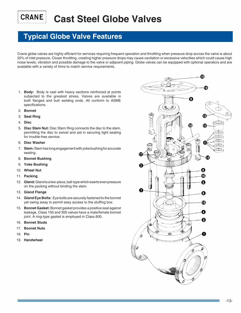
Crane globe valves are highly efficient for services requiring frequent operation and throttling when pressure drop across the valve is about 20% of inlet pressure. Closer throttling, creating higher pressure drops may cause cavitation or excessive velocities which could cause high noise levels, vibration and possible damage to the valve or adjacent piping. Globe valves can be equipped with optional operators and are available with a variety of trims to match service requirements.
�. Body: Body is cast with heavy sections reinforced at points subjected to the greatest stress. Valves are available in both flanged and butt welding ends. All conform to ASME specifications.
2. Bonnet
3. Seat Ring
4. Disc
5. Disc Stem Nut: Disc Stem Ring connects the disc to the stem, permitting the disc to swivel and aid in securing tight seating for trouble-free service.
6. Disc Washer
7. Stem: Stem has long engagement with yoke bushing for accurate seating.
8. Bonnet Bushing
9. Yoke Bushing
�0. Wheel Nut
��. Packing
�2. Gland: Gland is a two-piece, ball-type which exerts even pressure on the packing without binding the stem.
�3. Gland Flange
�4. Gland Eye Bolts: Eye bolts are securely fastened to the bonnet yet swing away to permit easy access to the stuffing box.
�5. Bonnet Gasket: Bonnet gasket provides a positive seal against leakage. Class �50 and 300 valves have a male/female bonnet joint. A ring-type gasket is employed in Class 600.
�6. Bonnet Studs
�7. Bonnet Nuts
�8. Pin
�9. Handwheel
-�4-
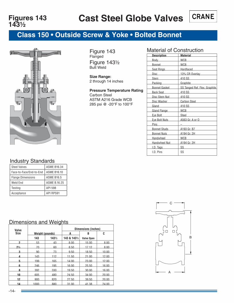
Figure �43Flanged
Figure �43½Butt Weld
Size Range:2 through �4 inches
Pressure Temperature RatingCarbon SteelASTM A2�6 Grade WCB285 psi @ -20°F to �00°F
Cast Steel Globe Valves
Class 150 • Outside Screw & Yoke • Bolted Bonnet
Figures 143143½
Material of Construction Description Material Body WCB Bonnet WCB SeatRings Hardfaced Disc 13%CROverlay Stem 410SS Packing Graphite BonnetGasket SSTangedRef.Flex.Graphite BackSeat 410SS DiscStemNut 410SS DiscWasher CarbonSteel Gland 410SS GlandFlange WCB EyeBolt Steel EyeBoltNuts A563Gr.AorO Pins – BonnetStuds A193Gr.B7 BonnetNuts A194Gr.2H Handwheel WCB HandwheelNut A194Gr.2H I.D.Tags SS I.D.Pins SS
C
B
A
Dimensions and Weights Dimensions (inches) Weight (pounds) A B C 143 143½ 143 & 143½ Valve Open
2 53 43 8.00 15.00 8.00 2½ 70 60 8.50 17.12 8.00 3 90 73 9.50 18.50 10.00 4 143 112 11.50 21.00 12.00 5 199 165 14.00 23.00 12.00 6 246 195 16.00 25.50 16.00 8 392 330 19.50 30.00 16.00 10 605 480 24.50 34.00 20.00 12 900 820 27.50 39.50 20.00 14 1000 880 31.00 41.38 24.00
ValveSize
SteelValves ASMEB16.34
Face-to-Face/End-to-End ASMEB16.10
FlangeDimensions ASMEB16.5
WeldEnd ASMEB.16.25
Testing API598
Acceptance APIRP591
Industry Standards

-�5-
Cast Steel Globe Valves
Class 300 • Outside Screw & Yoke • Bolted Bonnet
Figures 151151½
Figure �5�Flanged
Figure �5�½Butt Weld
Size Range:2 through �2 inches
Pressure Temperature RatingCarbon SteelASTM A2�6 Grade WCB740 psi @ -20°F to �00°F
Material of Construction Description Material Body WCB Bonnet WCB SeatRings Hardfaced Disc 13%CROverlay Stem 410SS Packing Graphite BonnetGasket 316SpiralWoundGraphite BackSeat 410SS DiscStemNut 410SS DiscWasher CarbonSteel Gland 410SS GlandFlange WCB EyeBolt Steel EyeBoltNuts A563Gr.AorO Pins – BonnetStuds A193Gr.B7 BonnetNuts A194Gr.2H Handwheel WCB HandwheelNut A194Gr.2H I.D.Tags SS I.D.Pins SS
C
B
A
Dimensions and Weights Dimensions (inches) Weight (pounds) A B C 151 151½ 151 & 151½ Valve Open
2 75 48 10.50 16.75 8.00 2½ 99 73 11.50 19.00 10.00 3 132 97 12.50 21.00 10.00 4 209 140 14.00 24.00 14.00 5 290 240 15.75 27.50 14.00 6 440 280 17.50 31.00 18.00 8 693 460 22.00 34.25 24.00 10 1008 620 24.50 37.00 24.00 12 1100 900 28.00 50.00 24.00
ValveSize
SteelValves ASMEB16.34
Face-to-Face/End-to-End ASMEB16.10
FlangeDimensions ASMEB16.5
WeldEnd ASMEB.16.25
Testing API598
Acceptance APIRP591
Industry Standards

-�6-
Figures 171171½
Cast Steel Globe Valves
Class 600 • Outside Screw & Yoke • Bolted Bonnet
Figure �7�Flanged
Figure �7�½Butt Weld
Size Range:2 through 8 inches
Pressure Temperature RatingCarbon SteelASTM A2�6 Grade WCB�480 psi @ -20°F to �00°F
Material of Construction Description Material Body WCB Bonnet WCB SeatRings Hardfaced Disc 13%CROverlay Stem 410SS Packing Graphite BonnetGasket RingTypeJoint BackSeat 410SS DiscStemNut 410SS DiscWasher CarbonSteel Gland 410SS GlandFlange WCB EyeBolt Steel EyeBoltNuts A563Gr.AorO Pins – BonnetStuds A193Gr.B7 BonnetNuts A194Gr.2H Handwheel WCB HandwheelNut A194Gr.2H I.D.Tags SS I.D.Pins SS
C
B
A
Dimensions and Weights Dimensions (inches) Weight (pounds) A B C 171 171½ 171 & 171½ Valve Open
2 88 79 11.50 18.75 10.00 2½ 126 100 13.00 20.25 10.00 3 160 135 14.00 23.00 14.00 4 270 215 17.00 26.50 18.00 6 550 490 22.00 27.00 20.00 8 1000 790 26.00 28.50 22.00
ValveSize
SteelValves ASMEB16.34
Face-to-Face/End-to-End ASMEB16.10
FlangeDimensions ASMEB16.5
WeldEnd ASMEB.16.25
Testing API598
Acceptance APIRP591
Industry Standards
-�7-
General Information • Class 150, 300, and 600 Valves
Cast Steel Check Valves
Disc Type • For class 600 valves, a ring joint bonnet gasket assures positive seal against leakage and accurate alignment of moving parts
Welded-in Seat Ring • Seat ring is seal welded to eliminate leak path.
• Standard material is ASTM A2�6 Grade WCB. • Standard trim is XU (�3% CR to hardface) which is suitable for a wide range of applications. • See “Technical Data” section for end flange dimensions and drilling templates. • Butt weld ends on valves 24" and smaller are bored to match standard pipe unless otherwise specified.
See “Engineering Data” catalog for details. • See “Technical Data” section for locations of bypasses, taps, and drains.
Features
Basic Standards
Notes
These valves comply with the applicable requirements of the following standards:
• API 598 • API RP59� • ASME B�6.34 • ASME B�6.25 • ASME B�6.�0 • ASME B�6.5
-�8-
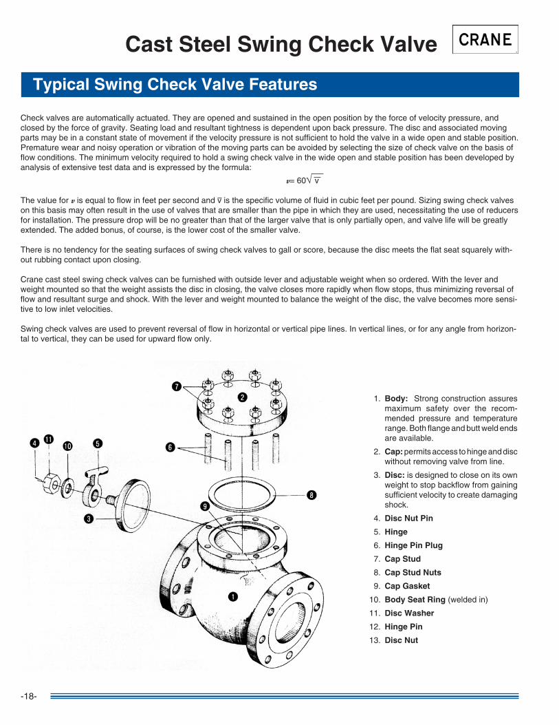
Typical Swing Check Valve Features
Cast Steel Swing Check Valve
�. Body: Strong construction assures maximum safety over the recom-mended pressure and temperature range. Both flange and butt weld ends are available.
2. Cap: permits access to hinge and disc without removing valve from line.
3. Disc: is designed to close on its own weight to stop backflow from gaining sufficient velocity to create damaging shock.
4. Disc Nut Pin
5. Hinge
6. Hinge Pin Plug
7. Cap Stud
8. Cap Stud Nuts
9. Cap Gasket
�0. Body Seat Ring (welded in)
��. Disc Washer
�2. Hinge Pin
�3. Disc Nut
Check valves are automatically actuated. They are opened and sustained in the open position by the force of velocity pressure, and closed by the force of gravity. Seating load and resultant tightness is dependent upon back pressure. The disc and associated moving parts may be in a constant state of movement if the velocity pressure is not sufficient to hold the valve in a wide open and stable position. Premature wear and noisy operation or vibration of the moving parts can be avoided by selecting the size of check valve on the basis of flow conditions. The minimum velocity required to hold a swing check valve in the wide open and stable position has been developed by analysis of extensive test data and is expressed by the formula:
v= 60√ v
The value for v is equal to flow in feet per second and v is the specific volume of fluid in cubic feet per pound. Sizing swing check valves on this basis may often result in the use of valves that are smaller than the pipe in which they are used, necessitating the use of reducers for installation. The pressure drop will be no greater than that of the larger valve that is only partially open, and valve life will be greatly extended. The added bonus, of course, is the lower cost of the smaller valve.
There is no tendency for the seating surfaces of swing check valves to gall or score, because the disc meets the flat seat squarely with-out rubbing contact upon closing.
Crane cast steel swing check valves can be furnished with outside lever and adjustable weight when so ordered. With the lever and weight mounted so that the weight assists the disc in closing, the valve closes more rapidly when flow stops, thus minimizing reversal of flow and resultant surge and shock. With the lever and weight mounted to balance the weight of the disc, the valve becomes more sensi-tive to low inlet velocities.
Swing check valves are used to prevent reversal of flow in horizontal or vertical pipe lines. In vertical lines, or for any angle from horizon-tal to vertical, they can be used for upward flow only.
-�9-
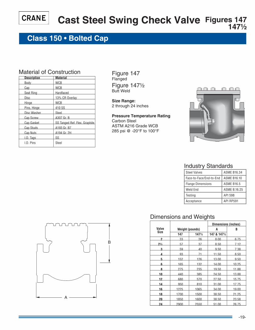
Figures 147147½
Cast Steel Swing Check Valve
Class 150 • Bolted Cap
Figure �47Flanged
Figure �47½Butt Weld
Size Range:2 through 24 inches
Pressure Temperature RatingCarbon SteelASTM A2�6 Grade WCB285 psi @ -20°F to �00°F
Material of Construction Description Material Body WCB Cap WCB SeatRing Hardfaced Disc 13%CROverlay Hinge WCB Pins,Hinge 410SS DiscWasher Steel CapScrew A307Gr.B CapGasket SSTangedRef.Flex.Graphite CapStuds A193Gr.B7 CapNuts A194Gr.2H I.D.Tags SS I.D.Pins Steel
B
A
Dimensions and Weights Dimensions (inches) Weight (pounds) A B 147 147½ 147 & 147½ 2 33 26 8.00 6.75 2½ 57 37 8.50 7.12 3 59 40 9.50 7.38 4 93 71 11.50 8.50 5 152 126 13.00 9.50 6 165 132 14.00 10.25 8 275 235 19.50 11.88 10 440 385 24.50 13.88 12 680 570 27.50 15.75 14 950 810 31.00 17.75 16 1225 1065 34.00 19.00 18 1700 1500 38.50 21.25 20 1850 1600 38.50 23.58 24 2900 2550 51.00 26.75
ValveSize
SteelValves ASMEB16.34
Face-to-Face/End-to-End ASMEB16.10
FlangeDimensions ASMEB16.5
WeldEnd ASMEB.16.25
Testing API598
Acceptance APIRP591
Industry Standards

-20-
Figure �59Flanged
Figure �59½Butt Weld
Size Range:2 through 24 inches
Pressure Temperature RatingCarbon SteelASTM A2�6 Grade WCB740 psi @ -20°F to �00°F
Figures 159159½
Cast Steel Swing Check Valve
Class 300 • Bolted Cap
Material of Construction Description Material Body WCB Cap WCB SeatRing Hardfaced Disc 13%CROverlay Hinge WCB Pins,Hinge 410SS DiscWasher Steel CapScrew A307Gr.B CapGasket 316SpiralWoundGraphite CapStuds A193Gr.B7 CapNuts A194Gr.2H I.D.Tags SS I.D.Pins Steel
B
A
Dimensions and Weights Dimensions (inches) Weight (pounds) A B 159 159½ 159 & 159½ 2 46 33 10.50 6.75 2½ 66 49 11.50 7.38 3 86 66 12.50 8.50 4 154 97 14.00 9.25 5 255 203 15.75 10.62 6 276 216 17.50 11.88 8 420 330 21.00 13.38 10 640 500 24.50 13.88 12 1000 830 28.00 16.62 14 1550 1100 33.00 18.88 16 1700 1400 34.00 20.50 18 2200 1900 38.50 23.62 20 2800 2425 40.00 26.38 24 3650 3100 53.00 29.62
ValveSize
SteelValves ASMEB16.34
Face-to-Face/End-to-End ASMEB16.10
FlangeDimensions ASMEB16.5
WeldEnd ASMEB.16.25
Testing API598
Acceptance APIRP591
Industry Standards
-2�-
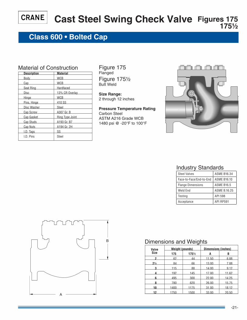
Figure �75Flanged
Figure �75½Butt Weld
Size Range:2 through �2 inches
Pressure Temperature RatingCarbon SteelASTM A2�6 Grade WCB�480 psi @ -20°F to �00°F
Cast Steel Swing Check Valve
Class 600 • Bolted Cap
Figures 175175½
Material of Construction Description Material Body WCB Cap WCB SeatRing Hardfaced Disc 13%CROverlay Hinge WCB Pins,Hinge 410SS DiscWasher Steel CapScrew A307Gr.B CapGasket RingTypeJoint CapStuds A193Gr.B7 CapNuts A194Gr.2H I.D.Tags SS I.D.Pins Steel
B
A
SteelValves ASMEB16.34
Face-to-Face/End-to-End ASMEB16.10
FlangeDimensions ASMEB16.5
WeldEnd ASMEB.16.25
Testing API598
Acceptance APIRP591
Industry Standards
Dimensions and Weights Weight (pounds) Dimensions (inches) 175 175½ A B 2 62 44 11.50 6.88 2½ 84 66 13.00 7.88 3 115 88 14.00 9.12 4 192 145 17.00 11.62 6 495 300 22.00 14.25 8 780 620 26.00 15.75 10 1400 1175 31.00 18.12 12 1750 1500 33.00 20.50
ValveSize
-22-
Cast Steel Tilting Disc Check Valve
General Information • Class 150, 300, and 600 Valves
• Reduced maintenance is assured because the disc is the only moving part and is designed to minimize flutter in the closed position, thus reducing wear on the pivot pin, disc, and seat.
• Loss of head is minimized by the balanced disc and its “aerofoil” design. Streamlined body without pockets contributes to straight-through flow.
• Short distance of travel, combined with a balanced disc allows rapid closure while minimizing slamming.
• Drop tight seating is accomplished over the full pressure range because a slight clearance at the pivot pin assures complete seating between the disc ring and body ring.
• Pivot pins are constructed of stainless steel.
These valves comply with the applicable requirements of the following standards:
• ASME B�6.34 • ASME B�6.�0 • ASME B�6.5
• Valves under 4" are typically supplied with “X” trim. • Valves 4" and larger are supplied with “XU” trim. • Butt weld ends on valves 24" and smaller are bored to match standard pipe unless otherwise specified. For larger valves, diameter (I.D. of pipe) of bore must be specified.
Features
Standards
Notes

-23-
Cast Steel Tilting Disc Check Valve
Typical Tilting Disc Check Valve
�. Body Inlet Half
2. Body Outlet Half
3. Disc
4. Pivot Pin
5. Body Gasket
6. Body Studs
7. Body Stud Nuts
8. Bearing Cap Gasket
9. Bearing Cap
�0. Bearing Cap Studs
��. Bearing Cap Stud Nuts
�2. Dowel Pins
Tilting Disc Check Valves consist of a cylindrical housing, with a pivoted circular disc. The pivots are located just above the center of the disc, and offset from the plane of the body seat. This design gives a bell-crank action to the disc. The seat is of circular bevel type and the disc drops in or out of contact without rubbing or sliding.
FeaturesSlamming of check valves is the result of failure of the valve disc to reach its closed position before the fluid flow reversal. Tilting disc check valves have to close rapidly since the disc has a shorter distance to travel and therefore arrives at the seat faster...minimizing a slam.
Tilting disc check valves are used to prevent reversal of flow in horizontal or vertical pipe lines. In vertical lines, or for any angle from hori-zontal to vertical, they can be used for upward flow only.
Tilting check valves are automatically actuated. They are opened by velocity pressure, and closed by gravity. Seating load and tightness is dependent on back pressure. The disc and moving parts may constantly move if the velocity pressure is not sufficient to hold the valve in a wide open and stable position. Premature wear and noisy operation or vibration of the moving parts can be avoided by selecting the size of check valve on the basis of flow conditions. The minimum velocity required to hold a tilting disc check valve wide open and stable can be determined by the formula:
v= 80√ vThe value for v is equal to flow in feet per second and where v is the specific volume of the fluid in cubic feet per pound. Sizing check valves on this basis may often result in the use of valves that are smaller than the pipe in which they are used, necessitating the use of reducers for installation. The pressure drop will not be greater than that of the larger valve that is only partially open, and valve life will be greatly extended. The added bonus, of course, is the lower cost of the smaller valve
Standard body design configurationsThe seat, disc and pivot pins are combined into one subassembly secured to the inlet side of the body with a locking ring in sizes 3" and smaller. This construction avoids the need for extending the pivot pins through the valve body.The seat formed on the end of the inlet body section by cobalt base alloy hard facing deposit in sizes 4" and larger. The pivot pins support-ing the disc are inserted through capped and gasketed bearing bosses in the outlet section of the body.
-24-
Class 150 • Bolted Cap
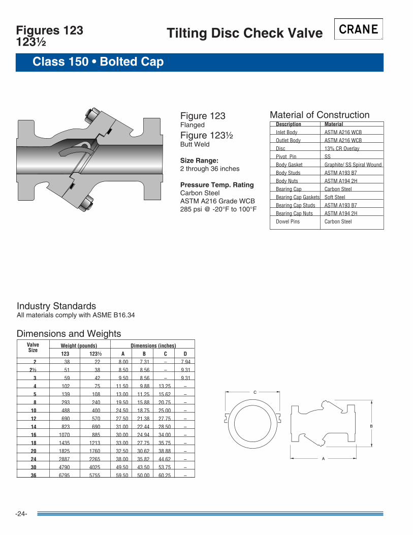
Tilting Disc Check ValveFigures 123123½
Figure �23Flanged
Figure �23½Butt Weld
Size Range:2 through 36 inches
Pressure Temp. RatingCarbon SteelASTM A2�6 Grade WCB285 psi @ -20°F to �00°F
CC
BB
AA
Material of Construction Description Material InletBody ASTMA216WCB OutletBody ASTMA216WCB Disc 13%CROverlay PivotPin SS BodyGasket Graphite/SSSpiralWound BodyStuds ASTMA193B7 BodyNuts ASTMA1942H BearingCap CarbonSteel BearingCapGaskets SoftSteel BearingCapStuds ASTMA193B7 BearingCapNuts ASTMA1942H DowelPins CarbonSteel
Industry StandardsAll materials comply with ASME B�6.34
Dimensions and Weights Weight (pounds) Dimensions (inches) 123 123½ A B C D 2 38 22 8.00 7.31 – 7.94 2½ 51 38 8.50 8.56 – 9.31 3 59 42 9.50 8.56 – 9.31 4 102 75 11.50 9.88 13.25 – 5 139 108 13.00 11.25 15.62 – 8 293 240 19.50 15.88 20.75 – 10 488 400 24.50 18.75 25.00 – 12 690 570 27.50 21.38 27.75 – 14 823 690 31.00 22.44 28.50 – 16 1070 885 30.00 24.94 34.00 – 18 1435 1213 33.00 27.75 35.75 – 20 1825 1760 32.50 30.62 38.88 – 24 2887 2265 38.00 35.82 44.62 – 30 4790 4025 49.50 43.50 53.75 – 36 6795 5755 59.50 50.00 60.25 –
ValveSize

-25-
Class 300 • Bolted Cap
Figure 323Flanged
Figure 323½Butt Weld
Size Range:2 through 36 inches
Pressure Temp. RatingCarbon SteelASTM A2�6 Grade WCB740 psi @ -20°F to �00°F
CC
BB
AA
Tilting Disc Check Valve Figures 323323½
Material of Construction Description Material InletBody ASTMA216WCB OutletBody ASTMA216WCB Disc 13%CROverlay PivotPin SS BodyGasket Graphite/SSSpiralWound BodyStuds ASTMA193B7 BodyNuts ASTMA1942H BearingCap CarbonSteel BearingCapGaskets SoftSteel BearingCapStuds ASTMA193B7 BearingCapNuts ASTMA1942H DowelPins CarbonSteel
Industry StandardsAll materials comply with ASME B�6.34
Dimensions and Weights Weight (pounds) Dimensions (inches) 323 323½ A B C D 2 57 38 10.50 8.06 – 8.50 2½ 85 58 11.50 9.50 – 9.88 3 90 60 12.50 9.50 – 9.88 4 167 106 14.00 10.75 14.25 – 5 215 166 15.75 12.50 16.38 – 8 457 338 21.00 17.00 22.00 – 10 670 520 24.50 20.25 25.12 – 12 1030 835 28.00 24.00 29.75 – 14 1245 1060 30.00 24.88 30.25 – 16 1695 1270 33.00 27.81 36.00 – 18 2180 1685 36.00 30.75 39.50 – 20 2648 1850 39.00 32.50 40.75 – 24 4070 2790 45.00 37.50 45.25 – 30 6200 4652 54.00 44.50 53.75 – 36 11853 10000 60.00 56.38 68.00 –
ValveSize
-26-
Class 600 • Bolted Cap
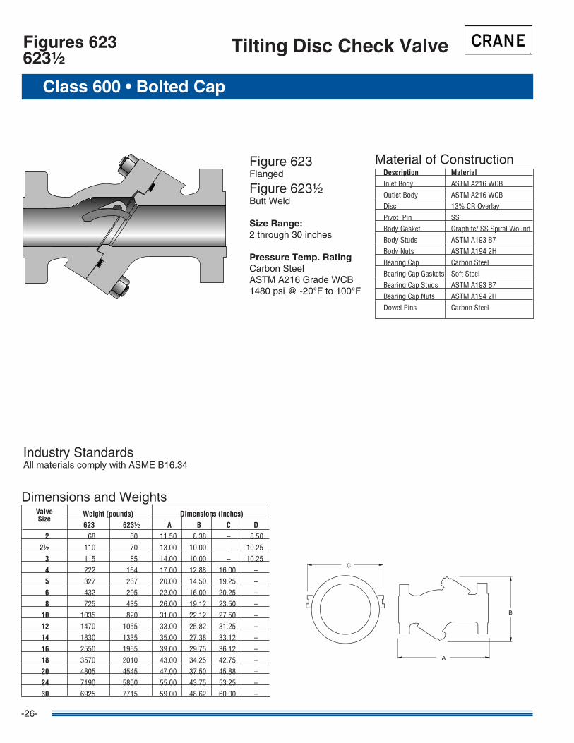
Tilting Disc Check ValveFigures 623623½
Figure 623Flanged
Figure 623½Butt Weld
Size Range:2 through 30 inches
Pressure Temp. RatingCarbon SteelASTM A2�6 Grade WCB�480 psi @ -20°F to �00°F
CC
BB
AA
Material of Construction Description Material InletBody ASTMA216WCB OutletBody ASTMA216WCB Disc 13%CROverlay PivotPin SS BodyGasket Graphite/SSSpiralWound BodyStuds ASTMA193B7 BodyNuts ASTMA1942H BearingCap CarbonSteel BearingCapGaskets SoftSteel BearingCapStuds ASTMA193B7 BearingCapNuts ASTMA1942H DowelPins CarbonSteel
Industry StandardsAll materials comply with ASME B�6.34
Dimensions and Weights Weight (pounds) Dimensions (inches) 623 623½ A B C D 2 68 60 11.50 8.38 – 8.50 2½ 110 70 13.00 10.00 – 10.25 3 115 85 14.00 10.00 – 10.25 4 222 164 17.00 12.88 16.00 – 5 327 267 20.00 14.50 19.25 – 6 432 295 22.00 16.00 20.25 – 8 725 435 26.00 19.12 23.50 – 10 1035 820 31.00 22.12 27.50 – 12 1470 1055 33.00 25.82 31.25 – 14 1830 1335 35.00 27.38 33.12 – 16 2550 1965 39.00 29.75 36.12 – 18 3570 2010 43.00 34.25 42.75 – 20 4805 4545 47.00 37.50 45.88 – 24 7190 5850 55.00 43.75 53.25 – 30 6925 7715 59.00 48.62 60.00 –
ValveSize
-27-
Class 900 • Bolted Cap
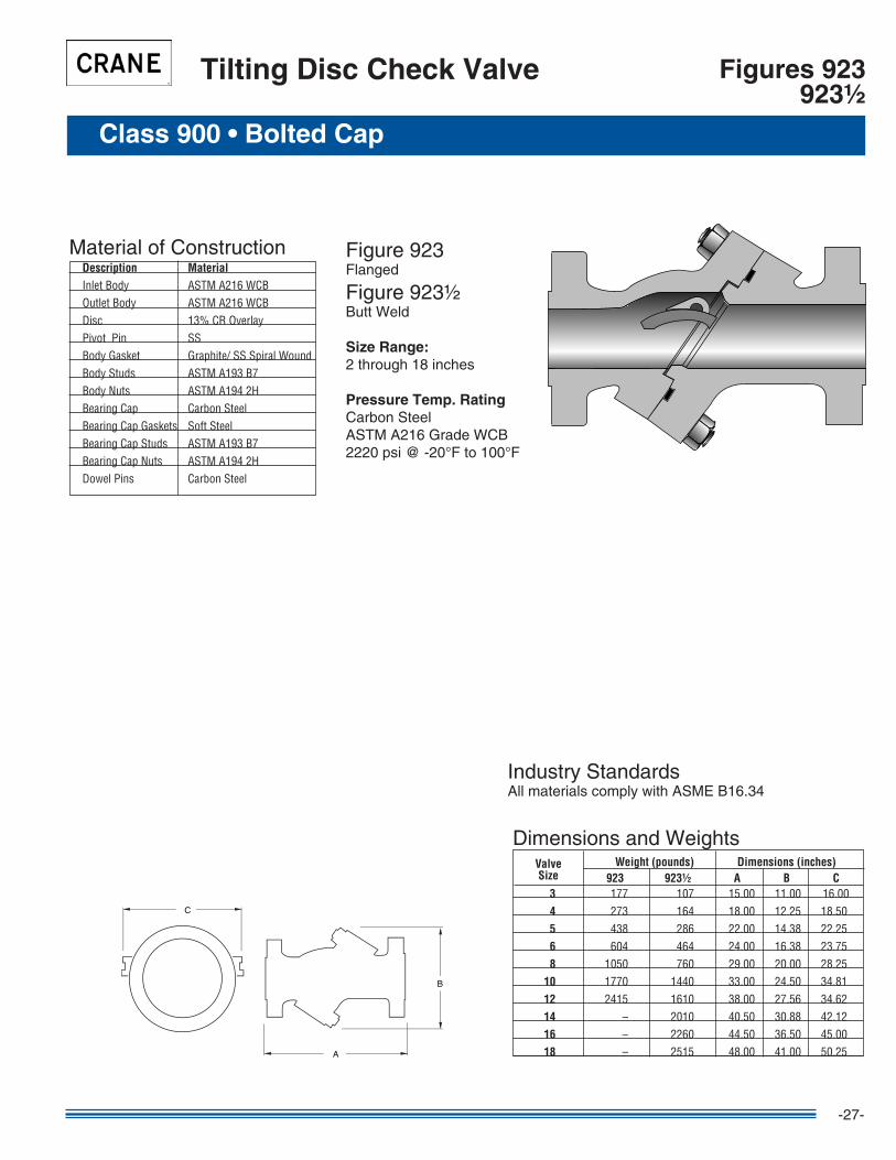
Tilting Disc Check Valve Figures 923923½
Figure 923Flanged
Figure 923½Butt Weld
Size Range:2 through �8 inches
Pressure Temp. RatingCarbon SteelASTM A2�6 Grade WCB2220 psi @ -20°F to �00°F
CC
BB
AA
Material of Construction Description Material InletBody ASTMA216WCB OutletBody ASTMA216WCB Disc 13%CROverlay PivotPin SS BodyGasket Graphite/SSSpiralWound BodyStuds ASTMA193B7 BodyNuts ASTMA1942H BearingCap CarbonSteel BearingCapGaskets SoftSteel BearingCapStuds ASTMA193B7 BearingCapNuts ASTMA1942H DowelPins CarbonSteel
Industry StandardsAll materials comply with ASME B�6.34
ValveSize
Dimensions and Weights
3 177 107 15.00 11.00 16.00 4 273 164 18.00 12.25 18.50 5 438 286 22.00 14.38 22.25 6 604 464 24.00 16.38 23.75 8 1050 760 29.00 20.00 28.25 10 1770 1440 33.00 24.50 34.81 12 2415 1610 38.00 27.56 34.62 14 – 2010 40.50 30.88 42.12 16 – 2260 44.50 36.50 45.00 18 – 2515 48.00 41.00 50.25
Weight (pounds) Dimensions (inches) 923 923½ A B C
-28-
Class 1500 • Bolted Cap
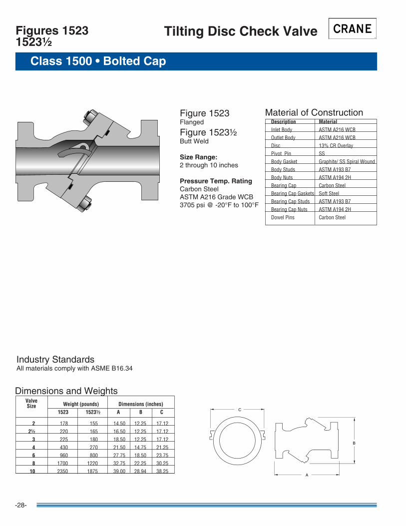
Tilting Disc Check ValveFigures 15231523½
Figure �523Flanged
Figure �523½Butt Weld
Size Range:2 through �0 inches
Pressure Temp. RatingCarbon SteelASTM A2�6 Grade WCB3705 psi @ -20°F to �00°F
CC
BB
AA
Material of Construction Description Material InletBody ASTMA216WCB OutletBody ASTMA216WCB Disc 13%CROverlay PivotPin SS BodyGasket Graphite/SSSpiralWound BodyStuds ASTMA193B7 BodyNuts ASTMA1942H BearingCap CarbonSteel BearingCapGaskets SoftSteel BearingCapStuds ASTMA193B7 BearingCapNuts ASTMA1942H DowelPins CarbonSteel
Industry StandardsAll materials comply with ASME B�6.34
Weight (pounds) Dimensions (inches) 1523 1523½ A B C 2 178 155 14.50 12.25 17.12 2½ 220 165 16.50 12.25 17.12 3 225 180 18.50 12.25 17.12 4 430 270 21.50 14.75 21.25 6 960 800 27.75 18.50 23.75 8 1700 1220 32.75 22.25 30.25 10 2350 1875 39.00 28.94 38.25
ValveSize
Dimensions and Weights
-29-
Stop Check Valve Information
Cast Steel Stop Check Valve
Stop Check Valves are as essential to safe operation of a boiler plant as safety valves or other safety devices attached to the boiler. The valves are intended to perform four important functions in boiler steam piping.
First: to act as an automatic non-return valve by preventing a backflow of steam from the main steam header to the boiler.
Second: to assist in cutting out a boiler, when ceasing to fire. In this case, the disc automatically closes and prevents header pressure from entering the boiler.
Third: To assist in bringing a boiler into service after a shutdown. This operation requires considerable care when performed manually, but is accomplished automatically by a stop check valve, without pressure fluctuations or disturbance of the water level.
Fourth: To act as a “safety first” valve by preventing backflow of steam from the header or for shutdown for inspection or repairs, should an attendant accidently open the valve.
When more than one boiler is connected to the main steam header, a stop check valve should be installed in the pipeline between each boiler and the header.
The valve should always be placed so that the pressure in the boiler is under the disc. Straightway valves may be used in horizontal or vertical lines for upward flow. Angle valves may be used for upward horizontal or horizontal downward flow.
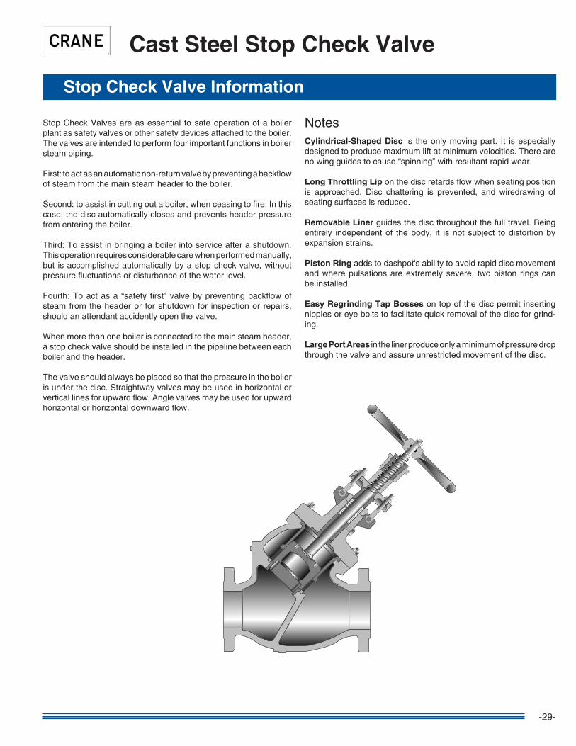
NotesCylindrical-Shaped Disc is the only moving part. It is especially designed to produce maximum lift at minimum velocities. There are no wing guides to cause “spinning” with resultant rapid wear.
Long Throttling Lip on the disc retards flow when seating position is approached. Disc chattering is prevented, and wiredrawing of seating surfaces is reduced.
Removable Liner guides the disc throughout the full travel. Being entirely independent of the body, it is not subject to distortion by expansion strains.
Piston Ring adds to dashpot's ability to avoid rapid disc movement and where pulsations are extremely severe, two piston rings can be installed.
Easy Regrinding Tap Bosses on top of the disc permit inserting nipples or eye bolts to facilitate quick removal of the disc for grind-ing.
Large Port Areas in the liner produce only a minimum of pressure drop through the valve and assure unrestricted movement of the disc.
-30-
Class 300 • Outside Screw & Yoke • Bolted Bonnet
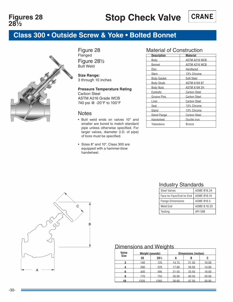
Figures 2828½
Stop Check Valve
CC
BB
AA
Material of Construction Description Material Body ASTMA216WCB Bonnet ASTMA216WCB Disc Hardfaced Stem 13%Chrome BodyGasket SoftSteel BodyStuds ASTMA194B7 BodyNuts ASTMA1942H Eyebolts CarbonSteel GroovePins CarbonSteel Liner CarbonSteel Seat 13%Chrome Gland 13%Chrome GlandFlange CarbonSteel Handwheel DuctileIron Yokesleeve Bronze
Figure 28Flanged
Figure 28½Butt Weld
Size Range:3 through �0 inches
Pressure Temperature RatingCarbon SteelASTM A2�6 Grade WCB740 psi @ -20°F to �00°F
Notes• Butt weld ends on valves �0" and
smaller are bored to match standard pipe unless otherwise specified. For larger valves, diameter (I.D. of pipe) of bore must be specified.
• Sizes 8" and �0", Class 300 are equipped with a hammer-blow handwheel.
SteelValves ASMEB16.34
Face-to-Face/End-to-End ASMEB16.10
FlangeDimensions ASMEB16.5
WeldEnd ASMEB.16.25
Testing API598
Industry Standards
Dimensions and Weights Weight (pounds) Dimensions (inches) 28 28½ A B C 3 140 125 14.75 21.50 10.00 4 260 225 17.00 26.50 14.00 6 430 395 21.50 33.50 18.00 8 770 755 26.00 40.50 20.00 10 1320 1265 30.00 47.50 30.00
ValveSize

-3�-
CC
BB
AA
AA
Figure 30Flanged
Figure 30½Butt Weld
Size Range:3 through �0 inches
Pressure Temperature RatingCarbon SteelASTM A2�6 Grade WCB740 psi @ -20°F to �00°F
NotesButt weld ends on valves �0" and smaller are bored to match standard pipe unless otherwise specified. For larger valves, diameter (I.D. of pipe) of bore must be specified.
Class 300 • Outside Screw & Yoke • Bolted Bonnet
Figures 3030½
Stop Check Valve
Material of Construction Description Material Body ASTMA216WCB Bonnet ASTMA216WCB Disc Hardfaced Stem 13%Chrome BodyGasket SoftSteel BodyStuds ASTMA194B7 BodyNuts ASTMA1942H Eyebolts CarbonSteel GroovePins CarbonSteel Liner CarbonSteel Seat 13%Chrome Gland 13%Chrome GlandFlange CarbonSteel Handwheel DuctileIron Yokesleeve Bronze
SteelValves ASMEB16.34
Face-to-Face/End-to-End ASMEB16.10
FlangeDimensions ASMEB16.5
WeldEnd ASMEB.16.25
Testing API598
Industry Standards
Dimensions and Weights Weight (pounds) Dimensions (inches) 30 30½ A B C 3 120 90 6.25 16.50 10.00 4 200 160 7.00 21.00 14.00 6 370 320 8.75 26.50 18.00 8 680 570 10.50 32.00 20.00 10 1120 970 12.25 38.00 30.00
ValveSize
-32-
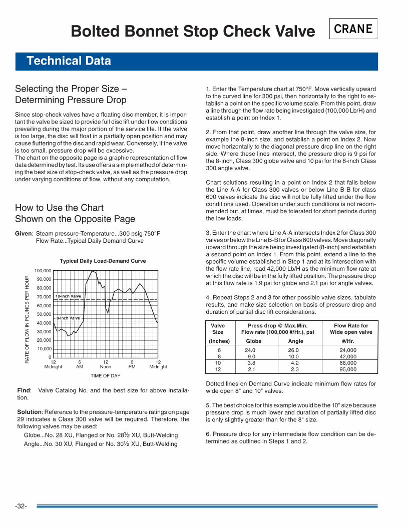
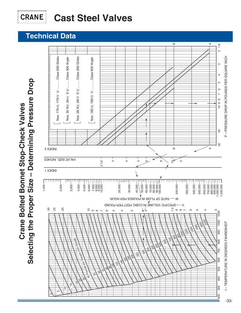
Selecting the Proper Size –Determining Pressure Drop
Since stop-check valves have a floating disc member, it is impor-tant the valve be sized to provide full disc lift under flow conditions prevailing during the major portion of the service life. If the valve is too large, the disc will float in a partially open position and may cause fluttering of the disc and rapid wear. Conversely, if the valve is too small, pressure drop will be excessive.The chart on the opposite page is a graphic representation of flow data determined by test. Its use offers a simple method of determin-ing the best size of stop-check valve, as well as the pressure drop under varying conditions of flow, without any computation.
How to Use the ChartShown on the Opposite Page
Given: Steam pressure-Temperature...300 psig 750°F Flow Rate...Typical Daily Demand Curve
Bolted Bonnet Stop Check Valve
Find: Valve Catalog No. and the best size for above installa-tion.
Solution: Reference to the pressure-temperature ratings on page 29 indicates a Class 300 valve will be required. Therefore, the following valves may be used:
Globe...No. 28 XU, Flanged or No. 28½ XU, Butt-Welding
Angle...No. 30 XU, Flanged or No. 30½ XU, Butt-Welding
�. Enter the Temperature chart at 750°F. Move vertically upward to the curved line for 300 psi, then horizontally to the right to es-tablish a point on the specific volume scale. From this point, draw a line through the flow rate being investigated (�00,000 Lb/H) and establish a point on Index �.
2. From that point, draw another line through the valve size, for example the 8-inch size, and establish a point on Index 2. Now move horizontally to the diagonal pressure drop line on the right side. Where these lines intersect, the pressure drop is 9 psi for the 8-inch, Class 300 globe valve and �0 psi for the 8-inch Class 300 angle valve.
Chart solutions resulting in a point on Index 2 that falls below the Line A-A for Class 300 valves or below Line B-B for class 600 valves indicate the disc will not be fully lifted under the flow conditions used. Operation under such conditions is not recom-mended but, at times, must be tolerated for short periods during the low loads.
3. Enter the chart where Line A-A intersects Index 2 for Class 300 valves or below the Line B-B for Class 600 valves. Move diagonally upward through the size being investigated (8-inch) and establish a second point on Index �. From this point, extend a line to the specific volume established in Step � and at its intersection with the flow rate line, read 42,000 Lb/H as the minimum flow rate at which the disc will be in the fully lifted position. The pressure drop at this flow rate is �.9 psi for globe and 2.� psi for angle valves.
4. Repeat Steps 2 and 3 for other possible valve sizes, tabulate results, and make size selection on basis of pressure drop and duration of partial disc lift considerations.
Dotted lines on Demand Curve indicate minimum flow rates for wide open 8" and �0" valves.
5. The best choice for this example would be the �0" size because pressure drop is much lower and duration of partially lifted disc is only slightly greater than for the 8" size.
6. Pressure drop for any intermediate flow condition can be de-termined as outlined in Steps � and 2.
Valve Press drop @ Max.Min. Flow Rate for Size Flow rate (100,000 #/Hr.), psi Wide open valve
(Inches) Globe Angle #/Hr.
6 24.0 26.0 24,000 8 9.0 �0.0 42,000 �0 3.8 4.2 68,000 �2 2.� 2.3 95,000
12Midnight
12Midnight
6AM
12Noon
6PM
0
TIME OF DAY
Typical Daily Load-Demand Curve
RA
TE
OF
FLO
W IN
PO
UN
DS
PE
R H
OU
R
10,000
20,000
30,000
40,000
50,000
60,000
70,000
80,000
90,000
100,000
10-Inch Valve
8-Inch Valve
Technical Data
-33-
.3
210B
B
AA
86543
2 1/
2
200
300
400
500
600
700
800
900
1000
1200
3020
109
87
65
43
21.
81,
200,
000
1,00
0,00
090
0,00
080
0,00
070
0,00
060
0,00
0
500,
000
400,
000
300,
000
200,
000
100,
000
90,0
0080
,000
70,0
00
60,0
00
50,0
00
40,0
00
30,0
00
20,0
00
10,0
009,
000
8,00
07,
000
6,00
0
5,00
0
4,00
0
3,00
0
2,00
0
1,00
0
.4.5.6.7.8.91.0
2345678910.20
.25
.30
2000
1800
1600
1400
1200
1000
900
800
700
600
500
450
400
350
300
250
200
180
160
140
120
100
908070
6050
40 P
ound
s pe
r Squ
are
Inch
Gau
ge
2520
15
10
5
0
30
V SPECIFIC VOLUME IN CUBIC FEET PER POUND
W RATE OF FLOW IN POUNDS PER HOUR
P –
PR
ES
SU
RE
DR
OP
IN P
OU
ND
S P
ER
SQ
UA
RE
INC
Ht –
TE
MP
ER
AT
UR
E IN
DE
GR
EE
S F
AH
RE
NH
EIT
VALVE SIZE, INCHES
INDEX 1
INDEX 2
Nos
. 179
U, 1
79
U
1/2
Nos
. 30
XU
, 30
X
U 1
/2
Nos
. 28
XU
, 28
X
U 1
/2
Nos
. 180
U, 1
80
U
1/2
Cla
ss 6
00 G
lobe
Cla
ss 3
00 A
ngle
Cla
ss 3
00 G
lobe
Cla
ss 6
00 A
ngle
Cra
ne
Bo
lted
Bo
nn
et S
top
-Ch
eck
Val
ves
Sel
ecti
ng
th
e P
rop
er S
ize
– D
eter
min
ing
Pre
ssu
re D
rop
Cast Steel Valves
Technical Data

-34-
Installation Recommendations
BOILER
BOILER
BOILER
BOILER
DRAIN
DRAIN
DRAIN
DRAIN
DRAIN
DRAIN
HEADER
HEADER
HEADER
HEADER
Straight-WayY-Pattern
Installed in ahorizontal line
Straight-WayY-Pattern
Installed in a vertical linefor upward flow
Angle Y-PatternInstalled for upward-
to-horizontal flow
Angle Y-PatternInstalled for
horizontal-to-downward flow
Y-Pattern Stop-Check and Isolation Gate Valves
As shown in these diagrams, Crane Y-Pattern stop-check valves used in a boiler installation can be positioned for horizontal or upward flow. The proper method for draining both Y-pattern stop-check valves and isolation gate valves is shown for typical mounting positions. Tapped and plugged drain holes can be furnished when specified. For top efficiency, be sure the proper size valve is used.
-35-
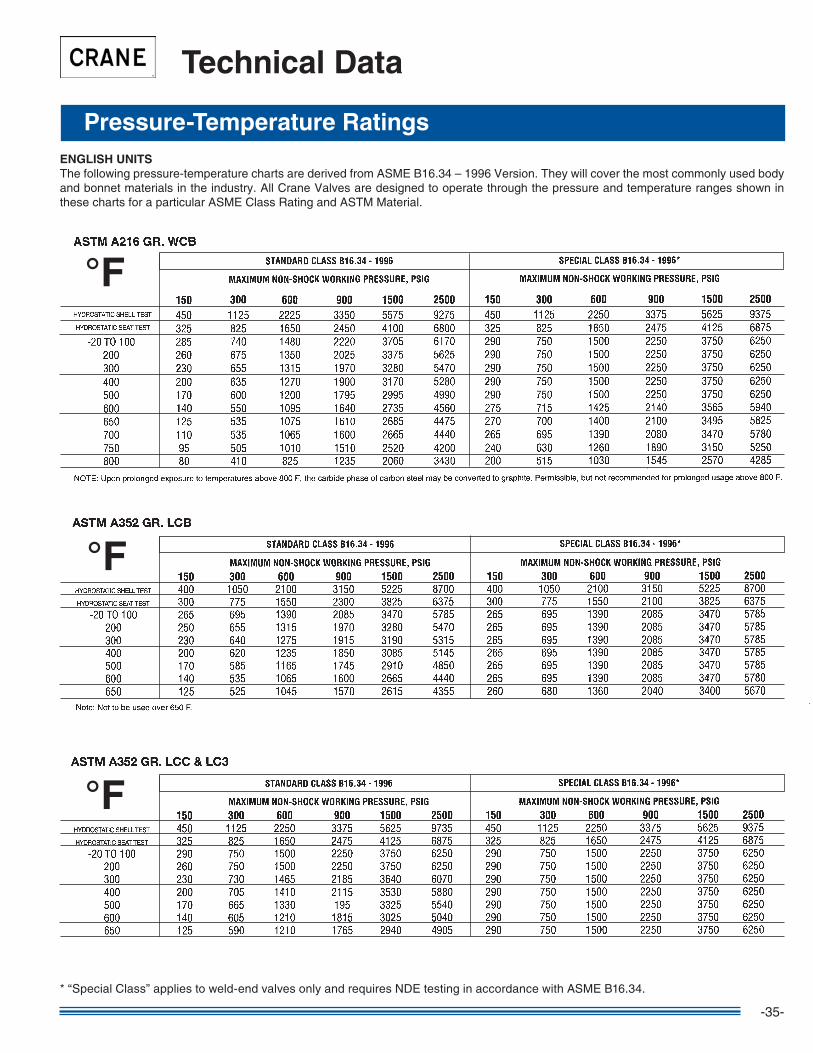
Pressure-Temperature Ratings
Technical Data
ENGLISH UNITSThe following pressure-temperature charts are derived from ASME B�6.34 – �996 Version. They will cover the most commonly used body and bonnet materials in the industry. All Crane Valves are designed to operate through the pressure and temperature ranges shown in these charts for a particular ASME Class Rating and ASTM Material.
* “Special Class” applies to weld-end valves only and requires NDE testing in accordance with ASME B�6.34.
°F
°F
°F
-36-
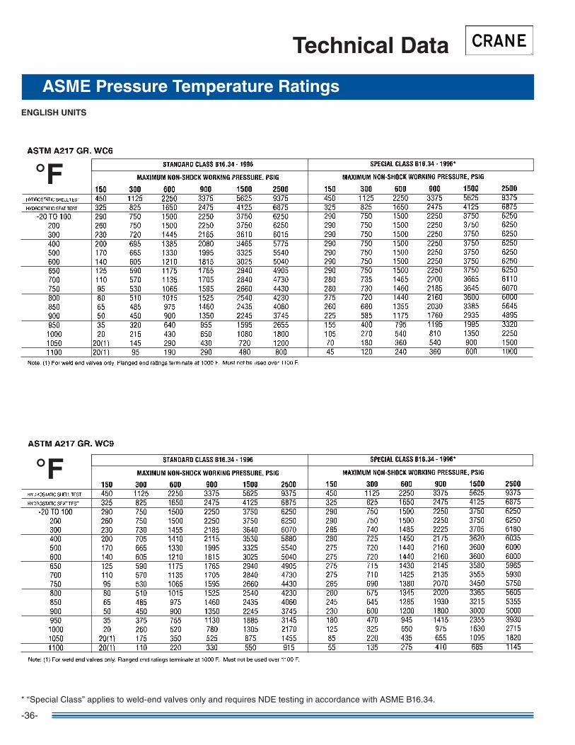
Technical Data
ASME Pressure Temperature RatingsENGLISH UNITS
* “Special Class” applies to weld-end valves only and requires NDE testing in accordance with ASME B�6.34.
°F
°F

-37-
Technical Data
ASME Pressure Temperature RatingsENGLISH UNITS
* “Special Class” applies to weld-end valves only and requires NDE testing in accordance with ASME B�6.34.
°F
°F
Global Headquarters9200 New Trails Drive, Suite 200
The Woodlands, Texas 7738�-52�9 Tel: 28�-298-5463Fax: 28�-298-�920
CV-20� 0�/07 A Crane Co. Company
CENTER LINE®
Resilient Seated Butterfly and Check ValvesPneumatic and Electric Actuators
Crane Energy Flow Solutionswww.cranevalve.com
Cullman, AL Operations2�29 3rd Avenue S.E.
Cullman, Alabama 35055 Tel: 256-775-3800Fax: 256-775-3860
CRANE®
Cast Steel, Bronze, and Iron Valves
Customer Service2�29 3rd Avenue S.E.
Cullman, Alabama 35055 Tel: 256-775-3800Fax: 256-775-3860
Crane, Center Line, Flowseal, Duo-Chek, Uni-Chek, Pacific, Jenkins, Aloyco, Noz-Chek, Compac-Noz and Wedgeplug
are all trademarks of Crane Co. ©2007
FLOWSEAL®
High Performance Butterfly Valves
DUO-CHEK®
High Performance Wafer Check Valves
UNI-CHEK®
Severe Service Check Valves
PACIFIC®
High Pressure and Severe Service ValvesQuarter Turn Severe Service Plug Valves
JENKINS®
Bronze, Iron, and Cast Steel Valves
ALOYCO®
Corrosion Resistant Gate, Globe and Check Valves
NOZ-CHEK® & COMPAC-NOZ®
Severe Service, Nozzle-Type Check Valves
WEDGEPLUG®
Severe Service, Metal-Seated Plug Valves
Related Documents