CITROËN C4 2004 Mechanics’ handbook 050 0019 «The technical information contained in this document is intended for the exclusive use of the trained personnel of the motor vehicle repair trade. In some instances, this information could concern the security and safety of the vehicle. The information is to be used by the professional vehicle repairers for whom it is intended and they alone would assume full responsibility to the exclusion of that of the manufacturer». «The technical information appearing in this brochure is subject to updating as the characteristics of each model in the range evolve. Motor vehicle repairers are invited to contact the CITROËN network periodically for further information and to obtain any possible updates».

Welcome message from author
This document is posted to help you gain knowledge. Please leave a comment to let me know what you think about it! Share it to your friends and learn new things together.
Transcript
CITROËN C4 2004CIT
RO
ËN
C4
Mechanics’ handbook 050 00192004AC/QCAV/MTD
Mechanics’ handbook� «The intellectual property rights relating to the technical information contained in this document belongexclusively to the manufacturer. Reproduction, translation or distribution in whole or in part without priorwritten authorisation from the manufacturer is forbidden».
«The technical information contained in this document is intended for the exclusive use of the trained personnelof the motor vehicle repair trade. In some instances, this information could concern the security and safety ofthe vehicle. The information is to be used by the professional vehicle repairers for whom it is intended and theyalone would assume full responsibility to the exclusion of that of the manufacturer».«The technical information appearing in this brochure is subject to updating as the characteristics of eachmodel in the range evolve. Motor vehicle repairers are invited to contact the CITROËN network periodically forfurther information and to obtain any possible updates».
UK-C4-Couv 2004 10/11/04 12:12 Page 2
VERY IMPORTANT
As the booklet is constantly re-edited, this one only covers vehicles for thisparticular model year.
It is therefore necessary to order a new booklet each year and RETAIN THEOLD ONES.
UK-C4-Couv 2004 10/11/04 12:12 Page 1
PRESENTATION
THIS HANDBOOK summarises the specifications, adjustments, checks and special features of the CITROEN C4.
The handbook is divided into nine groups representing the main functions :
GENERAL - ENGINE - INJECTION - IGNITION - CLUTCH, GEARBOX, DRIVESHAFTS - AXLES, SUSPENSION, STEERING - BRAKES - ELECTRICAL - AIR CONDITIONING
UK-C4-Index-2004 10/11/04 12:21 Page I
GE
NE
RA
L
1
IDENTIFICATION OF THE VEHICLE
E1AP0EWD
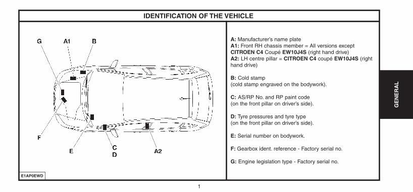
A: Manufacturer’s name plateA1: Front RH chassis member = All versions exceptCITROEN C4 Coupé EW10J4S (right hand drive)A2: LH centre pillar = CITROEN C4 coupé EW10J4S (righthand drive)
B: Cold stamp (cold stamp engraved on the bodywork).
C: AS/RP No. and RP paint code(on the front pillar on driver’s side).
D: Tyre pressures and tyre type(on the front pillar on driver’s side).
E: Serial number on bodywork.
F: Gearbox ident. reference - Factory serial no.
G: Engine legislation type - Factory serial no.
GE
NE
RA
L
UK-C4-page001-47-2004 15/11/04 9:26 Page 1

2
GE
NE
RA
L
IDENTIFICATION OF THE VEHICLE
Trim level Version
Level 1 � X
Level 2 � SX - VTR
Level 3 � VTR PACK - SX PACK
Level 4 � EXCLUSIVE - VTS
UK-C4-page001-47-2004 15/11/04 9:26 Page 2
GE
NE
RA
L
3
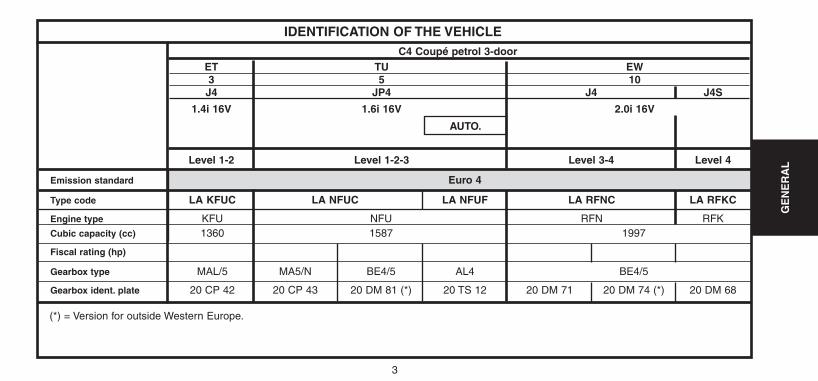
Emission standard Euro 4
Type code LA KFUC LA NFUC LA NFUF LA RFNC LA RFKC
Engine type KFU NFU RFN RFKCubic capacity (cc) 1360 1587 1997
Fiscal rating (hp)
Gearbox type MAL/5 MA5/N BE4/5 AL4 BE4/5
Gearbox ident. plate 20 CP 42 20 CP 43 20 DM 81 (*) 20 TS 12 20 DM 71 20 DM 74 (*) 20 DM 68
IDENTIFICATION OF THE VEHICLE
ET TU EW3 5 10J4 JP4 J4 J4S
1.4i 16V 1.6i 16V 2.0i 16V
Level 1-2 Level 1-2-3 Level 3-4 Level 4
(*) = Version for outside Western Europe.
C4 Coupé petrol 3-door
AUTO.
UK-C4-page001-47-2004 15/11/04 9:26 Page 3
4
GE
NE
RA
L
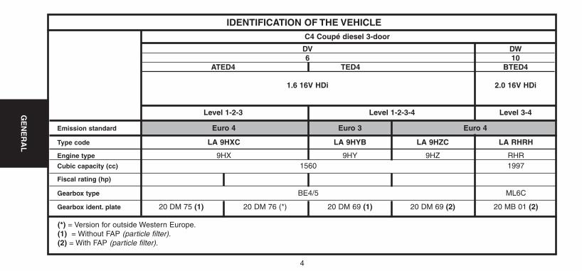
Emission standard Euro 4 Euro 3 Euro 4
Type code LA 9HXC LA 9HYB LA 9HZC LA RHRH
Engine type 9HX 9HY 9HZ RHRCubic capacity (cc) 1560 1997
Fiscal rating (hp)
Gearbox type BE4/5 ML6C
Gearbox ident. plate 20 DM 75 (1) 20 DM 76 (*) 20 DM 69 (1) 20 DM 69 (2) 20 MB 01 (2)
IDENTIFICATION OF THE VEHICLE
DV DW6 10
ATED4 TED4 BTED4
1.6 16V HDi 2.0 16V HDi
Level 1-2-3 Level 1-2-3-4 Level 3-4
(*) = Version for outside Western Europe.(1) = Without FAP (particle filter).(2) = With FAP (particle filter).
C4 Coupé diesel 3-door
UK-C4-page001-47-2004 15/11/04 9:26 Page 4
GE
NE
RA
LG
EN
ER
AL
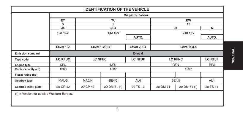
Emission standard Euro 4
Type code LC KFUC LC NFUC LC NFUF LC RFNC LC RFJF
Engine type KFU NFU RFN RFJCubic capacity (cc) 1360 1587 1997
Fiscal rating (hp)
Gearbox type MAL/5 MA5/N BE4/5 AL4 BE4/5 AL4
Gearbox ident. plate 20 CP 42 20 CP 43 20 DM 81 (*) 20 TS 12 20 DM 71 20 DM 74 (*) 20 TS 11
IDENTIFICATION OF THE VEHICLE
ET TU EW3 5 10J4 JP4 J4 A
1.4i 16V 1.6i 16V 2.0i 16V
Level 1-2 Level 1-2-3-4 Level 2-3-4 Level 2-3-4
(*) = Version for outside Western Europe.
C4 petrol 5-door
AUTO. AUTO.
5
UK-C4-page001-47-2004 15/11/04 9:26 Page 5
6
GE
NE
RA
L
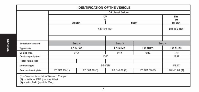
Emission standard Euro 4 Euro 3 Euro 4
Type code LC 9HXC LC 9HYB LC 9HZC LC RHRH
Engine type 9HX 9HY 9HZ RHRCubic capacity (cc) 1560 1997
Fiscal rating (hp)
Gearbox type BE4/5R ML6C
Gearbox ident. plate 20 DM 75 (1) 20 DM 76 (*) 20 DM 69 (1) 20 DM 69 (2) 20 MB 01 (2)
IDENTIFICATION OF THE VEHICLE
DV DW6 10
ATED4 TED4 BTED4
1.6 16V HDi 2.0 16V HDi
(*) = Version for outside Western Europe.(1) = Without FAP (particle filter).(2) = With FAP (particle filter).
C4 diesel 5-door
UK-C4-page001-47-2004 15/11/04 9:26 Page 6
7
GE
NE
RA
L
E1AP09JC
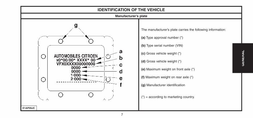
IDENTIFICATION OF THE VEHICLE
The manufacturer’s plate carries the following information:
(a) Type approval number (*)
(b) Type serial number (VIN)
(c) Gross vehicle weight (*)
(d) Gross vehicle weight (*)
(e) Maximum weight on front axle (*)
(f) Maximum weight on rear axle (*)
(g) Manufacturer identification
(*) = according to marketing country.
Manufacturer’s plate
UK-C4-page001-47-2004 15/11/04 9:26 Page 7
8
GE
NE
RA
L
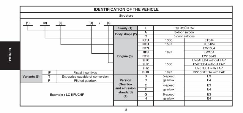
IF Fiscal incentivesVariants (5) T Entreprise capable of conversion
P Piloted gearbox
IDENTIFICATION OF THE VEHICLE
Structure
(1) (2) (3) (4) / (5)
Family (1) L CITROËN C4
Body shape (2)A 3-door saloonC 5-door saloons
KFU 1360 ET3J4NFU 1587 TU5JP4RFN EW10J4RFJ 1997 EW10A
Engine (3) RFK EW10J4S9HX DV6ATED4 without FAP9HY 1560 DV6TED4 without FAP9HZ DV6TED4 with FAPRHR 1997 DW10BTED4 with FAP
B 5-speed E3C gearbox E4
E 4-speed E3F gearbox E4
G 6-speed E3H gearbox E4
Version(Gearbox
and emission standard)
(4)Example : LC KFUC/IF
UK-C4-page001-47-2004 15/11/04 9:26 Page 8
9
GE
NE
RA
L
GENERAL SPECIFICATION: DIMENSIONS
E1AP0EXD
UK-C4-page001-47-2004 15/11/04 9:26 Page 9
10
GE
NE
RA
L
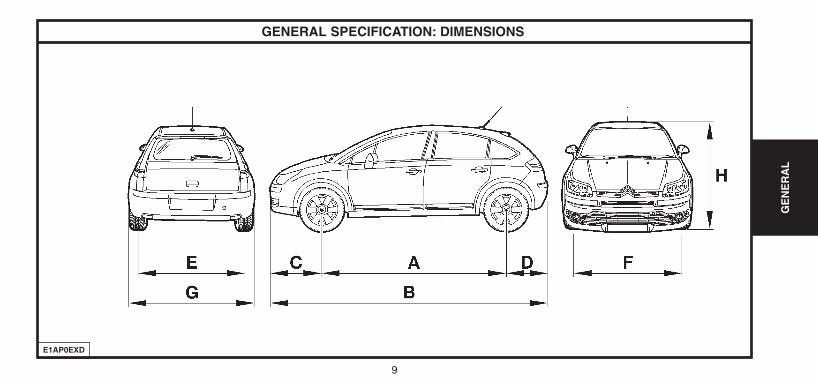
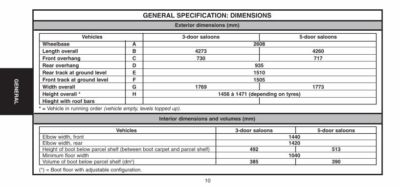
GENERAL SPECIFICATION: DIMENSIONS
* = Vehicle in running order (vehicle empty, levels topped up).
Exterior dimensions (mm)
Vehicles 3-door saloons 5-door saloonsWheelbase A 2608Length overall B 4273 4260Front overhang C 730 717Rear overhang D 935Rear track at ground level E 1510Front track at ground level F 1505Width overall G 1769 1773Height overall * H 1456 à 1471 (depending on tyres)Hieght with roof bars
Interior dimensions and volumes (mm)
(*) = Boot floor with adjustable configuration.
Vehicles 3-door saloons 5-door saloonsElbow width, front 1440Elbow width, rear 1420Height of boot below parcel shelf (between boot carpet and parcel shelf) 492 513Minimum floor width 1040Volume of boot below parcel shelf (dm3) 385 390
UK-C4-page001-47-2004 15/11/04 9:26 Page 10
11
GE
NE
RA
L
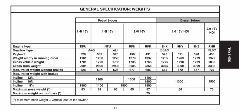
(*) Maximum nose weight = Vertical load at the towbar.
GENERAL SPECIFICATION: WEIGHTS
Petrol 3-door Diesel 3-door
1.4i 16V 1.6i 16V 2.0i 16V 1.6 16V HDi2.0 16V
HDi
Engine type KFU NFU RFN RFK 9HX 9HY 9HZ RHRGearbox type MA/5 AL4 BE4/5 ML6CPayload 520 532 520 456 431 520 521 520 456Weight empty in running order 1181 1200 1278 1279 1337 1255 1269 1279 1379Gross Vehicle weight 1701 1720 1798 1735 1768 1775 1790 1799 1835Gross Train weight 2901 2920 2998 3035 2868 3075 3090 3099 3335Max. trailer weight without brakes 628 637 628 677 686 665 672 677 727Max. trailer weight with brakesIncline 12% 1200 1300 1100Incline 10% 1500Incline 8% 1500 1400 1500 1800Maximum nose weight (*) 63 61 63 65 57 66 73Maximum weight on roof bars (*) 75
1300 15001200 1300
UK-C4-page001-47-2004 15/11/04 9:26 Page 11
12
GE
NE
RA
L
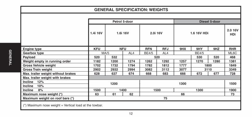
(*) Maximum nose weight = Vertical load at the towbar.
GENERAL SPECIFICATION: WEIGHTS
Petrol 5-door Diesel 5-door
1.4i 16V 1.6i 16V 2.0i 16V 1.6 16V HDi2.0 16V
HDi
Engine type KFU NFU RFN RFJ 9HX 9HY 9HZ RHRGearbox type MA/5 AL4 BE4/5 AL4 BE4/5 ML6CPayload 520 532 520 530 520 468Weight empty in running order 1182 1200 1274 1262 1292 1257 1270 1280 1381Gross Vehicle weight 1702 1732 1794 1782 1812 1777 1800 1849Gross Train weight 2902 2932 2994 3082 3112 3077 3110 3349Max. trailer weight without brakes 628 637 674 668 683 666 672 677 728Max. trailer weight with brakesIncline 12% 1200 1300 1500Incline 10%Incline 8% 1500 1400 1500 1300 1900Maximum nose weight (*) 63 61 62 66 73Maximum weight on roof bars (*) 75
1300 15001200
UK-C4-page001-47-2004 15/11/04 9:26 Page 12
13
GE
NE
RA
L
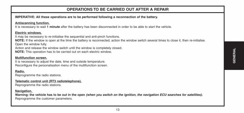
OPERATIONS TO BE CARRIED OUT AFTER A REPAIR
IMPERATIVE: All these operations are to be performed following a reconnection of the battery.
Antiscanning function.It is necessary to wait 1 minute after the battery has been disconnected in order to be able to start the vehicle.
Electric windows.It may be necessary to re-initialise the sequential and anti-pinch functions.NOTE: If the window is open at the time the battery is reconnected, action the window switch several times to close it, then re-initialise.Open the window fully.Action and release the window switch until the window is completely closed.NOTE: This operation has to be carried out on each electric window.
Multifunction screen.It is necessary to adjust the date, time and outside temperature.Reconfigure the personalisation menu of the multifunction screen.
Radio.Reprogramme the radio stations.
Telematic control unit (RT3 radiotelephone).Reprogramme the radio stations.
Navigation.Warning: the vehicle has to be out in the open (when you switch on the ignition, the navigation ECU searches for satellites).Reprogramme the customer parameters.
UK-C4-page001-47-2004 15/11/04 9:26 Page 13
14
GE
NE
RA
L
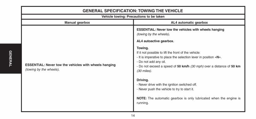
GENERAL SPECIFICATION: TOWING THE VEHICLEVehicle towing: Precautions to be taken
Manual gearbox AL4 automatic gearbox
ESSENTIAL: Never tow the vehicles with wheels hanging(towing by the wheels).
ESSENTIAL: Never tow the vehicles with wheels hanging(towing by the wheels).
AL4 autoactive gearbox.
Towing.If it not possible to lift the front of the vehicle:- It is imperative to place the selection lever in position «N».- Do not add any oil.- Do not exceed a speed of 50 km/h (30 mph) over a distance of 50 km(30 miles).
Driving.- Never drive with the ignition switched off.- Never push the vehicle to try to start it.
NOTE: The automatic gearbox is only lubricated when the engine isrunning.
UK-C4-page001-47-2004 15/11/04 9:26 Page 14
15
GE
NE
RA
L
GENERAL SPECIFICATION: TOWING THE VEHICLE
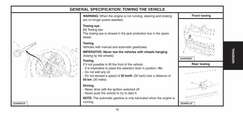
WARNING: When the engine is not running, steering and brakingare no longer power-assisted.
Towing eye.(1) Towing eye.The towing eye is stowed in the jack protection box in the sparewheel.
Towing.Vehicles with manual and automatic gearboxes.
IMPERATIVE: Never tow the vehicles with wheels hanging(towing by the wheels).
Towing.If it not possible to lift the front of the vehicle:- It is imperative to place the selection lever in position «N».- Do not add any oil.- Do not exceed a speed of 50 km/h (30 mph) over a distance of 50 km (30 miles).
Driving.- Never drive with the ignition switched off.- Never push the vehicle to try to start it.
NOTE: The automatic gearbox is only lubricated when the engine isrunning.
E2AP021D
E2AP02EC
E2AP01JC
Front towing
Rear towing
UK-C4-page001-47-2004 15/11/04 9:26 Page 15
16
GE
NE
RA
L
GENERAL SPECIFICATION: LIFTING AND SUPPORTING THE VEHICLE
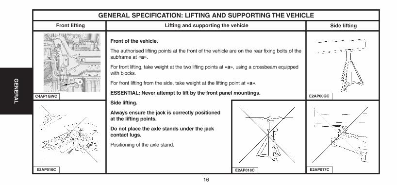
Front of the vehicle.
The authorised lifting points at the front of the vehicle are on the rear fixing bolts of thesubframe at «a».
For front lifting, take weight at the two lifting points at «a», using a crossbeam equippedwith blocks.
For front lifting from the side, take weight at the lifting point at «a».
ESSENTIAL: Never attempt to lift by the front panel mountings.
Side lifting.
Always ensure the jack is correctly positionedat the lifting points.
Do not place the axle stands under the jackcontact lugs.
Positioning of the axle stand.
E2AP016C
E2AP00GC
E2AP017C
Side liftingFront lifting
C4AP1GWC
Lifting and supporting the vehicle
E2AP018C
UK-C4-page001-47-2004 15/11/04 9:26 Page 16
17
GE
NE
RA
L
GENERAL SPECIFICATION: LIFTING AND SUPPORTING THE VEHICLELifting and supporting the vehicle (continued)
E2AP02HD
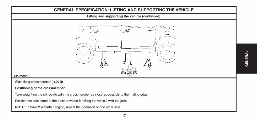
Side lifting crossmember (-).0010
Positioning of the crossmember.
Take weight on the sill rebate with the crossmember as close as possible to the mating edge.
Position the axle stand at the point provided for lifting the vehicle with the jack.
NOTE: To have 2 wheels hanging, repeat the operation on the other side.
UK-C4-page001-47-2004 15/11/04 9:26 Page 17
18
GE
NE
RA
L
GENERAL SPECIFICATION: LIFTING AND SUPPORTING THE VEHICLELifting and supporting the vehicle (continued)
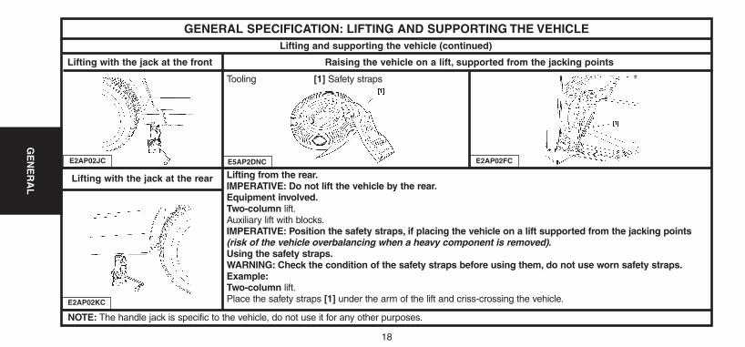
Lifting from the rear.IMPERATIVE: Do not lift the vehicle by the rear.Equipment involved.Two-column lift.Auxiliary lift with blocks.IMPERATIVE: Position the safety straps, if placing the vehicle on a lift supported from the jacking points(risk of the vehicle overbalancing when a heavy component is removed).Using the safety straps.WARNING: Check the condition of the safety straps before using them, do not use worn safety straps.Example:Two-column lift.Place the safety straps [1] under the arm of the lift and criss-crossing the vehicle.E2AP02KC
Lifting with the jack at the front
E2AP02JC
Raising the vehicle on a lift, supported from the jacking points
Lifting with the jack at the rear
E5AP2DNC E2AP02FC
NOTE: The handle jack is specific to the vehicle, do not use it for any other purposes.
Tooling [1] Safety straps
UK-C4-page001-47-2004 15/11/04 9:26 Page 18
19
GE
NE
RA
L
CAPACITIES (in litres)
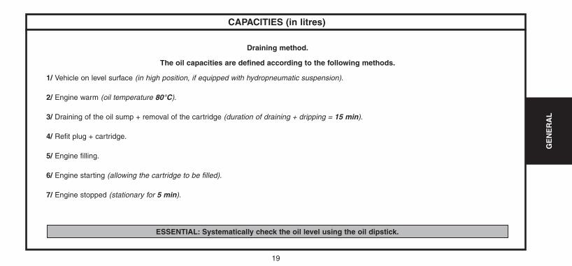
Draining method.
The oil capacities are defined according to the following methods.
1/ Vehicle on level surface (in high position, if equipped with hydropneumatic suspension).
2/ Engine warm (oil temperature 80°C).
3/ Draining of the oil sump + removal of the cartridge (duration of draining + dripping = 15 min).
4/ Refit plug + cartridge.
5/ Engine filling.
6/ Engine starting (allowing the cartridge to be filled).
7/ Engine stopped (stationary for 5 min).
ESSENTIAL: Systematically check the oil level using the oil dipstick.
UK-C4-page001-47-2004 15/11/04 9:26 Page 19
20
GE
NE
RA
L
Engine type
Oil capacity with change of cartridge
Between min. and max.
Manual gearbox
Automatic gearbox
After draining
Braking circuit
Cooling circuit
Manual gearbox
Automatic gearbox
Steering electro-pump reservoir
Fuel tank
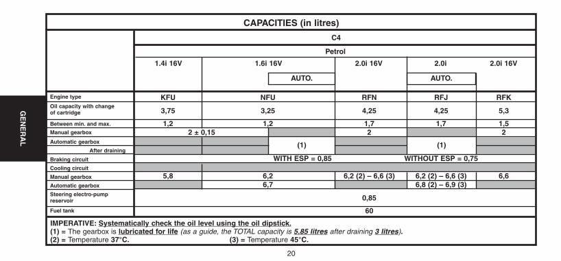
KFU NFU RFN RFJ RFK
3,75 3,25 4,25 4,25 5,3
1,2 1,2 1,7 1,7 1,52 ± 0,15 2 2
(1) (1)
WITH ESP = 0,85 WITHOUT ESP = 0,75
5,8 6,2 6,2 (2) – 6,6 (3) 6,2 (2) – 6,6 (3) 6,66,7 6,8 (2) – 6,9 (3)
0,85
60
CAPACITIES (in litres)
Petrol
C4
1.4i 16V 1.6i 16V 2.0i 16V 2.0i 2.0i 16V
IMPERATIVE: Systematically check the oil level using the oil dipstick.(1) = The gearbox is lubricated for life (as a guide, the TOTAL capacity is 5.85 litres after draining 3 litres).(2) = Temperature 37°C. (3) = Temperature 45°C.
AUTO.
(1)
AUTO.
(1)
UK-C4-page001-47-2004 15/11/04 9:26 Page 20
21
GE
NE
RA
L
Engine type
Oil capacity with change of cartridge
Between min. and max.
Manual gearbox
Braking circuit
Cooling circuit
Additive reservoir
Steering electro-pump reservoir
Fuel tank
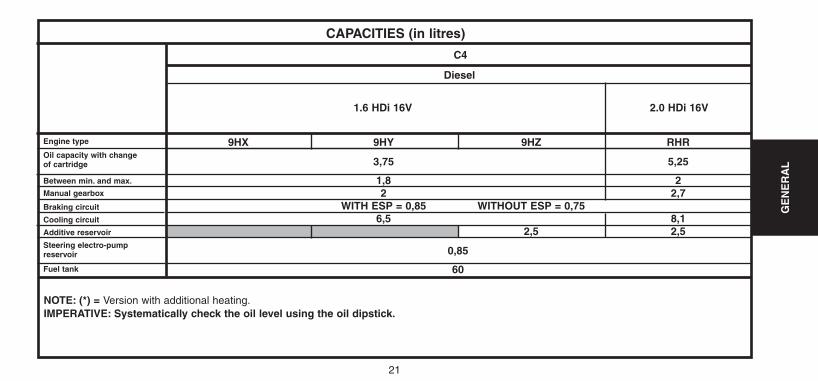
9HX 9HY 9HZ RHR
3,75 5,25
1,8 22 2,7
WITH ESP = 0,85 WITHOUT ESP = 0,756,5 8,1
2,5 2,5
0,85
60
CAPACITIES (in litres)
Diesel
C4
1.6 HDi 16V 2.0 HDi 16V
NOTE: (*) = Version with additional heating.IMPERATIVE: Systematically check the oil level using the oil dipstick.
UK-C4-page001-47-2004 15/11/04 9:26 Page 21
22
GE
NE
RA
L
LUBRICANTS - TOTAL recommended oils
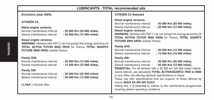
Evolutions (year 2004).
CITROËN C4.
Petrol engine versions.Normal maintenance interval : 30 000 Km (20 000 miles).Severe maintenance interval : 20 000 Km (12 000 miles).
Diesel engine versions.WARNING: Vehicles HDi FAP (*) do not accept the energy economy oilTOTAL ACTIVA FUTUR 9000 5W30 for France, TOTAL QUARTZFUTURE 9000 5W30 outside France.
Family DV6:Normal maintenance interval : 20 000 Km (12 500 miles).Severe maintenance interval : 15 000 Km (10 000 miles).
Family DW:Normal maintenance interval : 30 000 Km (20 000 miles).Severe maintenance interval : 20 000 Km (12 000 miles).
(*) FAP = Particle filter.
CITROËN C5 Restyled
Petrol engine versions.Normal maintenance interval : 30 000 Km (20 000 miles).Severe maintenance interval : 20 000 Km (12 000 miles).Diesel engine versions.WARNING: Vehicles HDi FAP (*) do not accept the energy economy oilTOTAL ACTIVA FUTUR 9000 5W30 for France, TOTAL QUARTZFUTURE 9000 5W30 outside France.
Family DV6:Normal maintenance interval : 20 000 Km (12 500 miles).Severe maintenance interval : 15 000 Km (10 000 miles).
Family DW:Normal maintenance interval : 30 000 Km (20 000 miles).Severe maintenance interval : 20 000 Km (12 000 miles).ESSENTIAL: For all vehicles with a 30 000 km (20 000 miles) mainte-nance interval, use exclusively TOTAL ACTIVA/QUARTZ 7000 or 9000or any other oils offering identical specifications to these.These oils offer specifications that are superior to those defined bynorms ACEA A3 OR API SJ/CF.Failing this, it is essential to adhere to the maintenance programmescovering severe operating conditions.
UK-C4-page001-47-2004 15/11/04 9:26 Page 22
23
GE
NE
RA
L
LUBRICANTS - TOTAL recommended oils
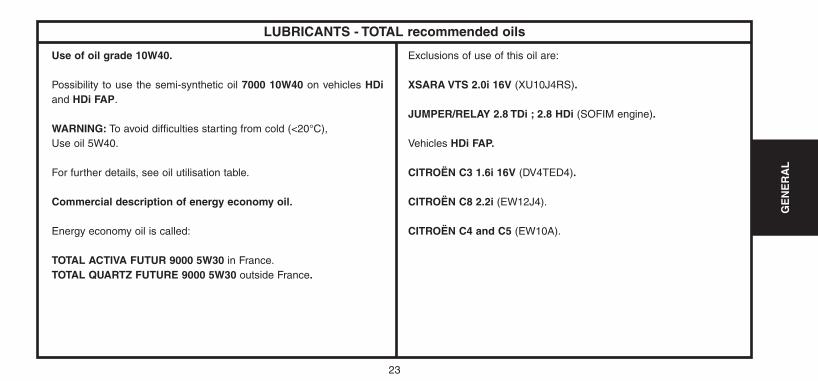
Use of oil grade 10W40.
Possibility to use the semi-synthetic oil 7000 10W40 on vehicles HDiand HDi FAP.
WARNING: To avoid difficulties starting from cold (<20°C),Use oil 5W40.
For further details, see oil utilisation table.
Commercial description of energy economy oil.
Energy economy oil is called:
TOTAL ACTIVA FUTUR 9000 5W30 in France.TOTAL QUARTZ FUTURE 9000 5W30 outside France.
Exclusions of use of this oil are:
XSARA VTS 2.0i 16V (XU10J4RS).
JUMPER/RELAY 2.8 TDi ; 2.8 HDi (SOFIM engine).
Vehicles HDi FAP.
CITROËN C3 1.6i 16V (DV4TED4).
CITROËN C8 2.2i (EW12J4).
CITROËN C4 and C5 (EW10A).
UK-C4-page001-47-2004 15/11/04 9:26 Page 23
24
GE
NE
RA
L
LUBRICANTS - TOTAL recommended oils
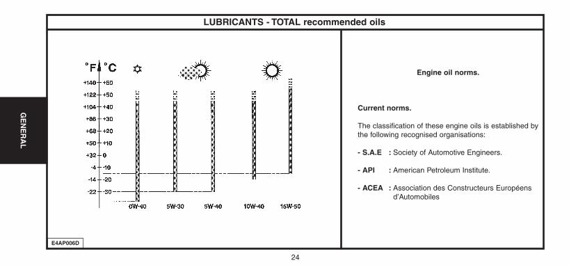
Engine oil norms.
Current norms.
The classification of these engine oils is established bythe following recognised organisations:
- S.A.E : Society of Automotive Engineers.
- API : American Petroleum Institute.
- ACEA : Association des Constructeurs Européensd’Automobiles
E4AP006D
UK-C4-page001-47-2004 15/11/04 9:26 Page 24
25
GE
NE
RA
L
LUBRICANTS - TOTAL recommended oils
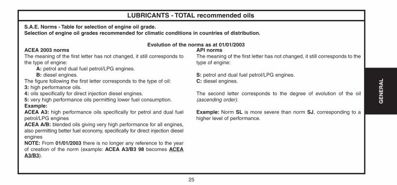
S.A.E. Norms - Table for selection of engine oil grade.Selection of engine oil grades recommended for climatic conditions in countries of distribution.
Evolution of the norms as at 01/01/2003API normsThe meaning of the first letter has not changed, it still corresponds to thetype of engine:
S: petrol and dual fuel petrol/LPG engines.C: diesel engines.
The second letter corresponds to the degree of evolution of the oil(ascending order).
Example: Norm SL is more severe than norm SJ, corresponding to ahigher level of performance.
ACEA 2003 normsThe meaning of the first letter has not changed, it still corresponds tothe type of engine:
A: petrol and dual fuel petrol/LPG engines.B: diesel engines.
The figure following the first letter corresponds to the type of oil:3: high performance oils.4: oils specifically for direct injection diesel engines.5: very high performance oils permitting lower fuel consumption.Example:ACEA A3: high performance oils specifically for petrol and dual fuelpetrol/LPG engines ACEA A/B: blended oils giving very high performance for all engines,also permitting better fuel economy, specifically for direct injection dieselengines NOTE: From 01/01/2003 there is no longer any reference to the yearof creation of the norm (example: ACEA A3/B3 98 becomes ACEAA3/B3).
UK-C4-page001-47-2004 15/11/04 9:26 Page 25
26
GE
NE
RA
L
LUBRICANTS - TOTAL recommended oils
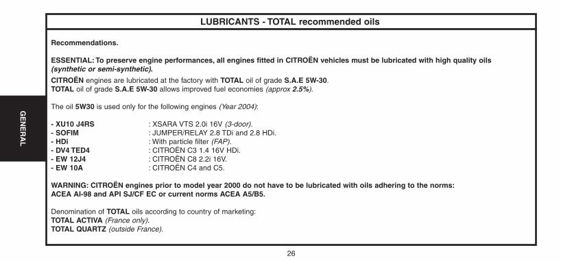
Recommendations.
ESSENTIAL: To preserve engine performances, all engines fitted in CITROËN vehicles must be lubricated with high quality oils(synthetic or semi-synthetic).
CITROËN engines are lubricated at the factory with TOTAL oil of grade S.A.E 5W-30.TOTAL oil of grade S.A.E 5W-30 allows improved fuel economies (approx 2.5%).
The oil 5W30 is used only for the following engines (Year 2004):
- XU10 J4RS : XSARA VTS 2.0i 16V (3-door).- SOFIM : JUMPER/RELAY 2.8 TDi and 2.8 HDi.- HDi : With particle filter (FAP).- DV4 TED4 : CITROËN C3 1.4 16V HDi.- EW 12J4 : CITROËN C8 2.2i 16V.- EW 10A : CITROËN C4 and C5.
WARNING: CITROËN engines prior to model year 2000 do not have to be lubricated with oils adhering to the norms:ACEA AI-98 and API SJ/CF EC or current norms ACEA A5/B5.
Denomination of TOTAL oils according to country of marketing:TOTAL ACTIVA (France only).TOTAL QUARTZ (outside France).
UK-C4-page001-47-2004 15/11/04 9:26 Page 26
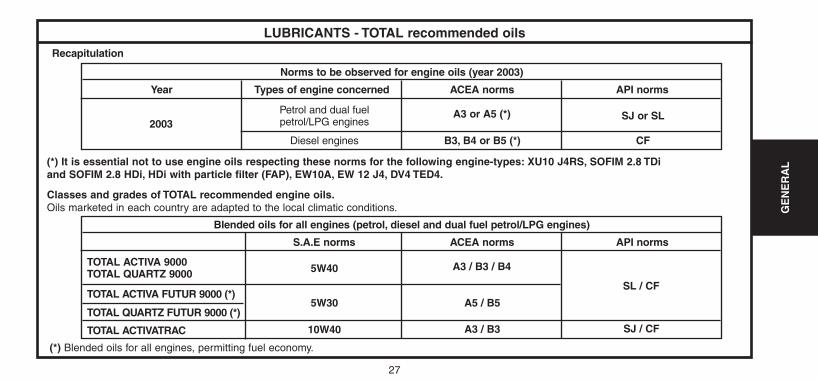
Year
2003Petrol and dual fuel petrol/LPG engines
A3 or A5 (*) SJ or SL
CFB3, B4 or B5 (*)Diesel engines
Types of engine concerned
Norms to be observed for engine oils (year 2003)
ACEA norms API norms
Recapitulation
27
GE
NE
RA
L
LUBRICANTS - TOTAL recommended oils
TOTAL ACTIVATRAC
TOTAL QUARTZ FUTUR 9000 (*)
TOTAL ACTIVA FUTUR 9000 (*)
TOTAL ACTIVA 9000TOTAL QUARTZ 9000 5W40 A3 / B3 / B4
SL / CF
SJ / CF
A5 / B5
A3 / B3
5W30
10W40
S.A.E norms
Blended oils for all engines (petrol, diesel and dual fuel petrol/LPG engines)
ACEA norms API norms
(*) It is essential not to use engine oils respecting these norms for the following engine-types: XU10 J4RS, SOFIM 2.8 TDiand SOFIM 2.8 HDi, HDi with particle filter (FAP), EW10A, EW 12 J4, DV4 TED4.
Classes and grades of TOTAL recommended engine oils.Oils marketed in each country are adapted to the local climatic conditions.
(*) Blended oils for all engines, permitting fuel economy.
UK-C4-page001-47-2004 15/11/04 9:26 Page 27
28
GE
NE
RA
L
LUBRICANTS - TOTAL recommended oils
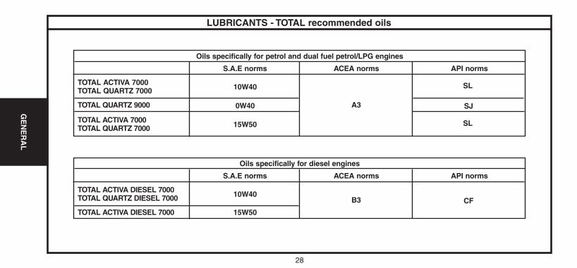
TOTAL ACTIVA 7000TOTAL QUARTZ 7000
TOTAL QUARTZ 9000
TOTAL ACTIVA 7000TOTAL QUARTZ 7000 10W40
A3 SJ0W40
15W50
S.A.E norms
Oils specifically for petrol and dual fuel petrol/LPG engines
ACEA norms API norms
TOTAL ACTIVA DIESEL 7000
TOTAL ACTIVA DIESEL 7000TOTAL QUARTZ DIESEL 7000 10W40
B3 CF
15W50
S.A.E norms
Oils specifically for diesel engines
ACEA norms API norms
SL
SL
UK-C4-page001-47-2004 15/11/04 9:26 Page 28
29
GE
NE
RA
L
LUBRICANTS - TOTAL recommended oils
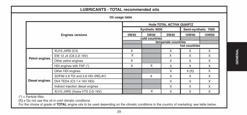
Huile TOTAL ACTIVA QUARTZ
Semi-synthetic 7000Synthetic 9000
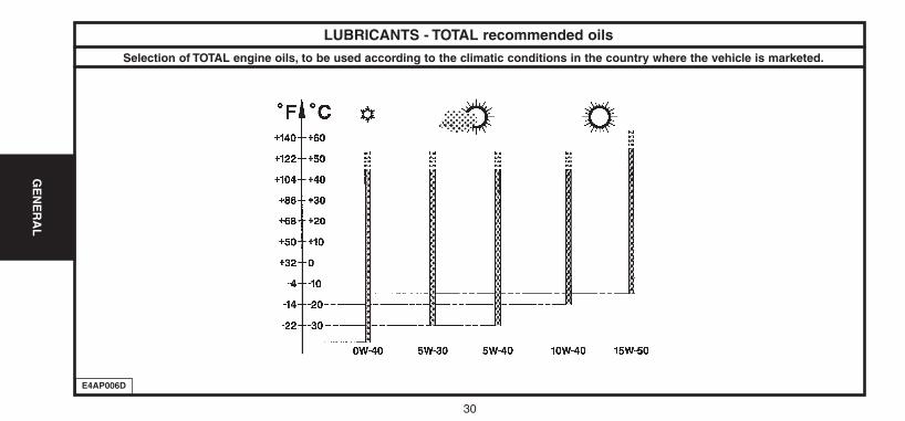
0W40 5W30 5W40 10W40 15W50cold countries
temperate countrieshot countries
Engines versions
XU10 J4RS (C4) X
X
X
Other petrol engines
HDi engines with FAP (*)
Other HDi engines
SOFIM 2.8 TDi and 2.8 HDi (RELAY)
DV4 TED4 (C3 1.4 16V HDi)
Indirect injection diesel engines
XU10 J4RS (Xsara VTS 2.0i 16V)
Petrol engines
Diesel engines
Oil usage table
X
X
X
X X X
X X X
X X X
X X (1)
X X X
X X X
X X X
X X X
(*) = Particle filter.(1) = Do not use this oil in cold climatic conditions.For the choice of grade of TOTAL engine oils to be used depending on the climatic conditions in the country of marketing: see table below.
X
EW 12 J4 (C8 2.2i 16V) X X X X
UK-C4-page001-47-2004 15/11/04 9:26 Page 29
30
GE
NE
RA
L
LUBRICANTS - TOTAL recommended oils
Selection of TOTAL engine oils, to be used according to the climatic conditions in the country where the vehicle is marketed.
E4AP006D
UK-C4-page001-47-2004 15/11/04 9:26 Page 30
31
GE
NE
RA
L
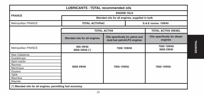
FRANCE
Metropolitan FRANCE
Metropolitan FRANCE
New CaledoniaGuadeloupeSaint martinReunion
9000 5W40 7000 15W50 7000 15W50MartiniqueGuyanaTahitiMauritiusMayotte
LUBRICANTS - TOTAL recommended oils
Blended oils for all engines, supplied in bulk
ENGINE OILS
TOTAL ACTIVRAC S.A.E norms: 10W40
TOTAL ACTIVA
Blended oils for all engines
900 5W409000 5W30 (*)
7000 10W407000 10W409000 5W40
Oils specifically for petrol anddual-fuel petrol/LPG engines
Oils specifically for dieselengines
TOTAL ACTIVA DIESEL
(*) Blended oils for all engines, permitting fuel economy.
UK-C4-page001-47-2004 15/11/04 9:26 Page 31
32
GE
NE
RA
L
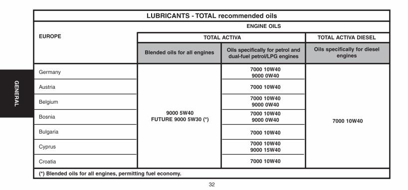
EUROPE
7000 10W409000 0W40
7000 10W40
7000 10W409000 0W40
7000 10W409000 0W40
7000 10W40
7000 10W409000 15W40
7000 10W40
Germany
Austria
Belgium
Bosnia
Bulgaria
Cyprus
Croatia
LUBRICANTS - TOTAL recommended oils
ENGINE OILS
TOTAL ACTIVA
Blended oils for all engines Oils specifically for petrol anddual-fuel petrol/LPG engines
Oils specifically for dieselengines
TOTAL ACTIVA DIESEL
9000 5W40FUTURE 9000 5W30 (*) 7000 10W40
(*) Blended oils for all engines, permitting fuel economy.
UK-C4-page001-47-2004 15/11/04 9:26 Page 32
33
GE
NE
RA
L
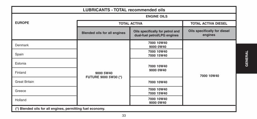
EUROPE
7000 10W409000 0W407000 10W407000 15W40
7000 10W409000 0W40
7000 10W40
7000 10W407000 15W40
7000 10W409000 0W40
Denmark
Spain
Estonia
Finland
Great Britain
Greece
Holland
LUBRICANTS - TOTAL recommended oils
ENGINE OILS
TOTAL ACTIVA
Blended oils for all engines Oils specifically for petrol anddual-fuel petrol/LPG engines
Oils specifically for dieselengines
TOTAL ACTIVA DIESEL
9000 5W40FUTURE 9000 5W30 (*) 7000 10W40
(*) Blended oils for all engines, permitting fuel economy.
UK-C4-page001-47-2004 15/11/04 9:26 Page 33
34
GE
NE
RA
L
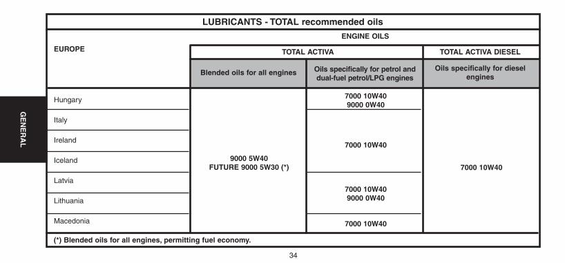
EUROPE
7000 10W409000 0W40
7000 10W40
7000 10W409000 0W40
7000 10W40
Hungary
Italy
Ireland
Iceland
Latvia
Lithuania
Macedonia
LUBRICANTS - TOTAL recommended oils
ENGINE OILS
TOTAL ACTIVA
Blended oils for all engines Oils specifically for petrol anddual-fuel petrol/LPG engines
Oils specifically for dieselengines
TOTAL ACTIVA DIESEL
9000 5W40FUTURE 9000 5W30 (*) 7000 10W40
(*) Blended oils for all engines, permitting fuel economy.
UK-C4-page001-47-2004 15/11/04 9:26 Page 34
35
GE
NE
RA
L
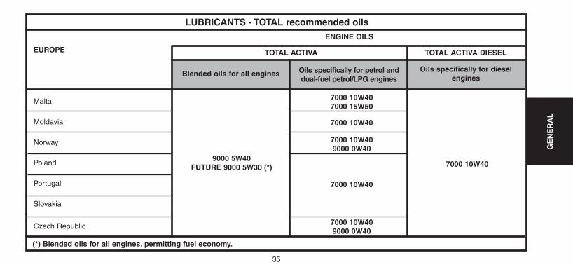
EUROPE
7000 10W407000 15W50
7000 10W40
7000 10W409000 0W40
7000 10W40
7000 10W409000 0W40
Malta
Moldavia
Norway
Poland
Portugal
Slovakia
Czech Republic
LUBRICANTS - TOTAL recommended oils
ENGINE OILS
TOTAL ACTIVA
Blended oils for all engines Oils specifically for petrol anddual-fuel petrol/LPG engines
Oils specifically for dieselengines
TOTAL ACTIVA DIESEL
9000 5W40FUTURE 9000 5W30 (*) 7000 10W40
(*) Blended oils for all engines, permitting fuel economy.
UK-C4-page001-47-2004 15/11/04 9:26 Page 35
36
GE
NE
RA
L
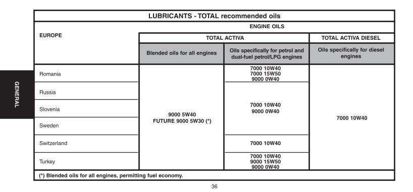
EUROPE
7000 10W407000 15W509000 0W40
7000 10W409000 0W40
7000 10W40
7000 10W409000 15W509000 0W40
Romania
Russia
Slovenia
Sweden
Switzerland
Turkey
LUBRICANTS - TOTAL recommended oils
ENGINE OILS
TOTAL ACTIVA
Blended oils for all engines Oils specifically for petrol anddual-fuel petrol/LPG engines
Oils specifically for dieselengines
TOTAL ACTIVA DIESEL
9000 5W40FUTURE 9000 5W30 (*) 7000 10W40
(*) Blended oils for all engines, permitting fuel economy.
UK-C4-page001-47-2004 15/11/04 9:26 Page 36
37
GE
NE
RA
L
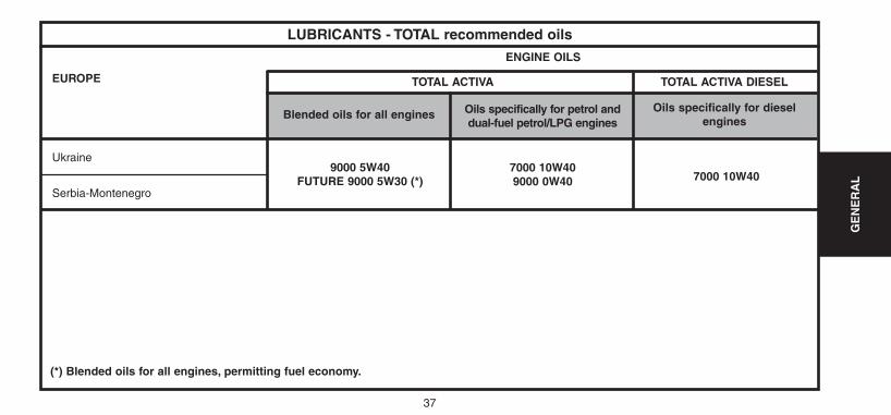
EUROPE
7000 10W409000 0W40
Ukraine
Serbia-Montenegro
LUBRICANTS - TOTAL recommended oils
ENGINE OILS
TOTAL ACTIVA
Blended oils for all engines Oils specifically for petrol anddual-fuel petrol/LPG engines
Oils specifically for dieselengines
TOTAL ACTIVA DIESEL
9000 5W40FUTURE 9000 5W30 (*) 7000 10W40
(*) Blended oils for all engines, permitting fuel economy.
UK-C4-page001-47-2004 15/11/04 9:26 Page 37
38
GE
NE
RA
L
OCEANIA
AFRICA
7000 10W40Australia
New Zealand
Algeria, South Africa,
Ivory Coast, Egypt,
Gabon, Ghana, Kenya,
Madagascar, Morocco,
Nigeria, Senegal, Tunisia
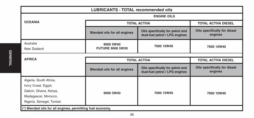
LUBRICANTS - TOTAL recommended oils
ENGINE OILS
TOTAL ACTIVA
Blended oils for all engines Oils specifically for petrol anddual-fuel petrol / LPG engines
Oils specifically for dieselengines
TOTAL ACTIVA DIESEL
9000 5W40FUTURE 9000 5W30 7000 10W40
7000 15W50
TOTAL ACTIVA
Blended oils for all engines Oils specifically for petrol anddual-fuel petrol / LPG engines
Oils specifically for dieselengines
TOTAL ACTIVA DIESEL
9000 5W40 7000 10W40
(*) Blended oils for all engines, permitting fuel economy.
UK-C4-page001-47-2004 15/11/04 9:26 Page 38
39
GE
NE
RA
L
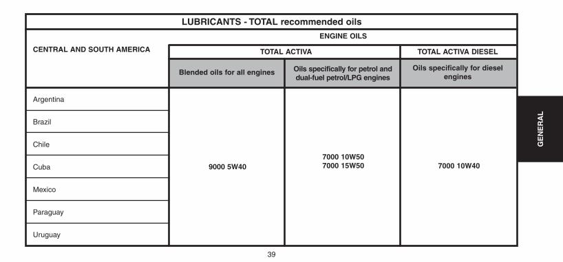
CENTRAL AND SOUTH AMERICA
Argentina
Brazil
Chile
Cuba
Mexico
Paraguay
Uruguay
LUBRICANTS - TOTAL recommended oils
7000 10W507000 15W50
ENGINE OILS
TOTAL ACTIVA
Blended oils for all engines Oils specifically for petrol anddual-fuel petrol/LPG engines
Oils specifically for dieselengines
TOTAL ACTIVA DIESEL
9000 5W40 7000 10W40
UK-C4-page001-47-2004 15/11/04 9:26 Page 39
40
GE
NE
RA
L
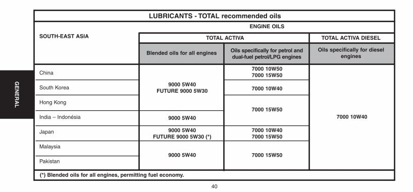
SOUTH-EAST ASIA
China
South Korea
Hong Kong
India – Indonésia
Japan
Malaysia
Pakistan
LUBRICANTS - TOTAL recommended oils
7000 10W507000 15W50
7000 10W40
7000 15W50
7000 10W407000 15W50
7000 15W50
ENGINE OILS
TOTAL ACTIVA
Blended oils for all engines Oils specifically for petrol anddual-fuel petrol/LPG engines
Oils specifically for dieselengines
TOTAL ACTIVA DIESEL
9000 5W40FUTURE 9000 5W30
9000 5W40
9000 5W40FUTURE 9000 5W30 (*)
9000 5W40
7000 10W40
(*) Blended oils for all engines, permitting fuel economy.
UK-C4-page001-47-2004 15/11/04 9:26 Page 40
41
GE
NE
RA
L
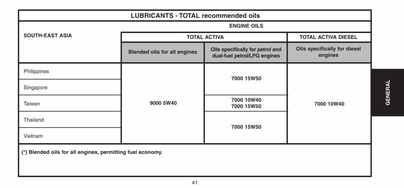
SOUTH-EAST ASIA
Philippines
Singapore
Taiwan
Thailand
Vietnam
LUBRICANTS - TOTAL recommended oils
7000 15W50
7000 10W407000 15W50
7000 15W50
ENGINE OILS
TOTAL ACTIVA
Blended oils for all engines Oils specifically for petrol anddual-fuel petrol/LPG engines
Oils specifically for dieselengines
TOTAL ACTIVA DIESEL
9000 5W40 7000 10W40
(*) Blended oils for all engines, permitting fuel economy.
UK-C4-page001-47-2004 15/11/04 9:26 Page 41
42
GE
NE
RA
L
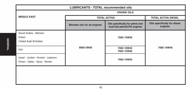
MIDDLE EAST
7000 15W50
7000 10W407000 15W50
7000 15W50
Saudi Arabia - Bahrain
Dubai
United Arab Emirates
Iran
Israel - Jordan - Kuwait - Lebanon
Oman - Qatar - Syria - Yemen
LUBRICANTS - TOTAL recommended oils
ENGINE OILS
TOTAL ACTIVA
Blended oils for all engines Oils specifically for petrol anddual-fuel petrol/LPG engines
Oils specifically for dieselengines
TOTAL ACTIVA DIESEL
9000 5W40 7000 10W40
UK-C4-page001-47-2004 15/11/04 9:26 Page 42
43
GE
NE
RA
L
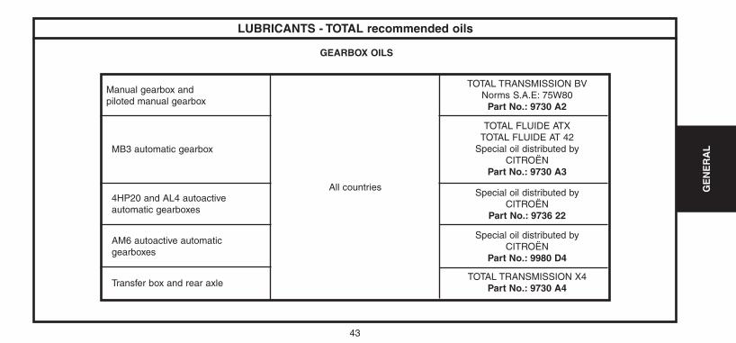
LUBRICANTS - TOTAL recommended oils
GEARBOX OILS
TOTAL TRANSMISSION BVNorms S.A.E: 75W80
Part No.: 9730 A2
TOTAL FLUIDE ATXTOTAL FLUIDE AT 42
Special oil distributed byCITROËN
Part No.: 9730 A3
Special oil distributed byCITROËN
Part No.: 9736 22
Manual gearbox andpiloted manual gearbox
MB3 automatic gearbox
4HP20 and AL4 autoactive automatic gearboxes
All countries
Special oil distributed byCITROËN
Part No.: 9980 D4
TOTAL TRANSMISSION X4Part No.: 9730 A4
AM6 autoactive automatic gearboxes
Transfer box and rear axle
UK-C4-page001-47-2004 15/11/04 9:26 Page 43
44
GE
NE
RA
L
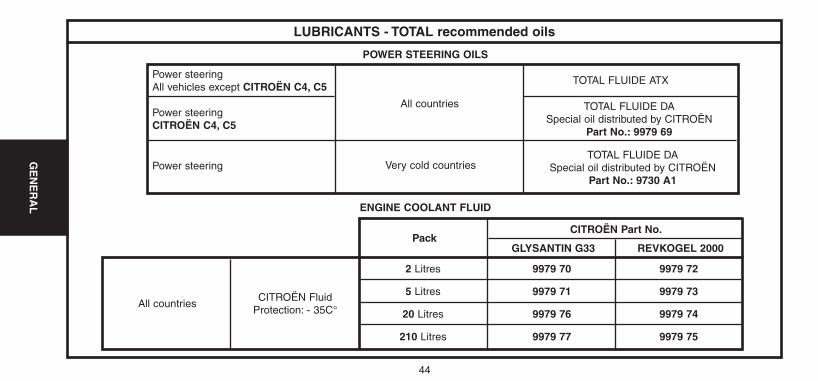
LUBRICANTS - TOTAL recommended oils
POWER STEERING OILS
ENGINE COOLANT FLUID
TOTAL FLUIDE ATX
TOTAL FLUIDE DASpecial oil distributed by CITROËN
Part No.: 9979 69
Power steering
All countries
All countriesCITROËN Fluid
Protection: - 35C°
2 Litres
5 Litres
20 Litres
210 Litres
9979 70
9979 71
9979 76
9979 77
9979 72
9979 73
9979 74
9979 75
PackCITROËN Part No.
REVKOGEL 2000GLYSANTIN G33
TOTAL FLUIDE DASpecial oil distributed by CITROËN
Part No.: 9730 A1Very cold countries
Power steeringAll vehicles except CITROËN C4, C5
Power steeringCITROËN C4, C5
UK-C4-page001-47-2004 15/11/04 9:26 Page 44
45
GE
NE
RA
L
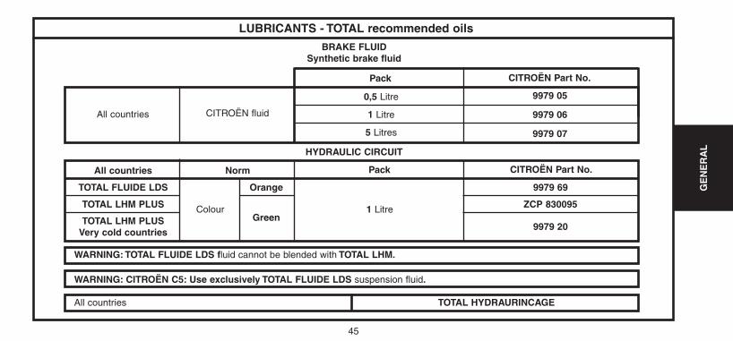
LUBRICANTS - TOTAL recommended oils
BRAKE FLUIDSynthetic brake fluid
HYDRAULIC CIRCUIT
WARNING: TOTAL FLUIDE LDS fluid cannot be blended with TOTAL LHM.
WARNING: CITROËN C5: Use exclusively TOTAL FLUIDE LDS suspension fluid.
All countries TOTAL HYDRAURINCAGE
All countries CITROËN fluid
0,5 Litre
1 Litre
5 Litres
9979 05
9979 06
9979 07
Pack CITROËN Part No.
Pack CITROËN Part No.Norm
Colour
All countries
TOTAL FLUIDE LDS
TOTAL LHM PLUS
TOTAL LHM PLUSVery cold countries
Orange 9979 69
ZCP 830095
9979 20Green
1 Litre
UK-C4-page001-47-2004 15/11/04 9:26 Page 45
46
GE
NE
RA
L
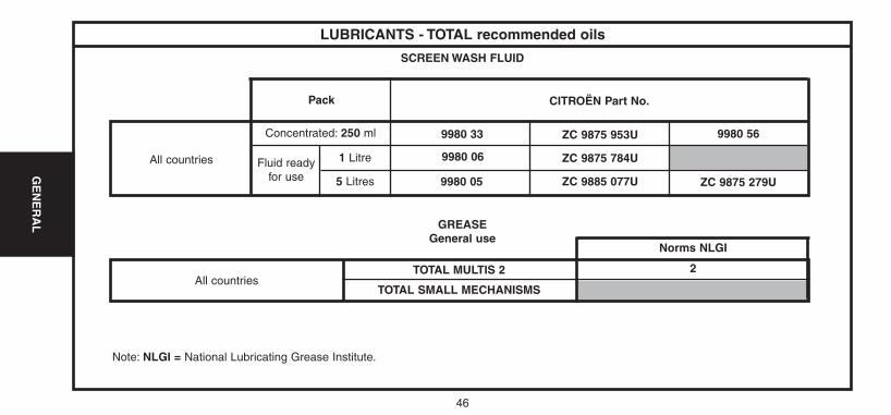
SCREEN WASH FLUID
GREASEGeneral use
All countries
Concentrated: 250 ml
Fluid readyfor use
9980 33
9980 06
9980 05
ZC 9875 953U
ZC 9875 784U
ZC 9885 077U
9980 56
ZC 9875 279U
Pack CITROËN Part No.
LUBRICANTS - TOTAL recommended oils
1 Litre
5 Litres
Norms NLGI
2TOTAL MULTIS 2
TOTAL SMALL MECHANISMSAll countries
Note: NLGI = National Lubricating Grease Institute.
UK-C4-page001-47-2004 15/11/04 9:26 Page 46
47
GE
NE
RA
L
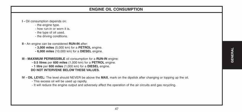
ENGINE OIL CONSUMPTION
I - Oil consumption depends on:- the engine type.- how run-in or worn it is.- the type of oil used.- the driving conditions.
II - An engine can be considered RUN-IN after:- 3,000 miles (5,000 km) for a PETROL engine.- 6,000 miles (10,000 km) for a DIESEL engine.
III - MAXIMUM PERMISSIBLE oil consumption for a RUN-IN engine:- 0.5 litres per 600 miles (1,000 km) for a PETROL engine.- 1 litre per 600 miles (1,000 km) for a DIESEL engine.
DO NOT INTERVENE BELOW THESE VALUES.
IV - OIL LEVEL: The level should NEVER be above the MAX. mark on the dipstick after changing or topping up the oil.- This excess oil will be used up rapidly.- It will reduce the engine output and adversely affect the operation of the air circuits and gas recycling.
UK-C4-page001-47-2004 15/11/04 9:26 Page 47
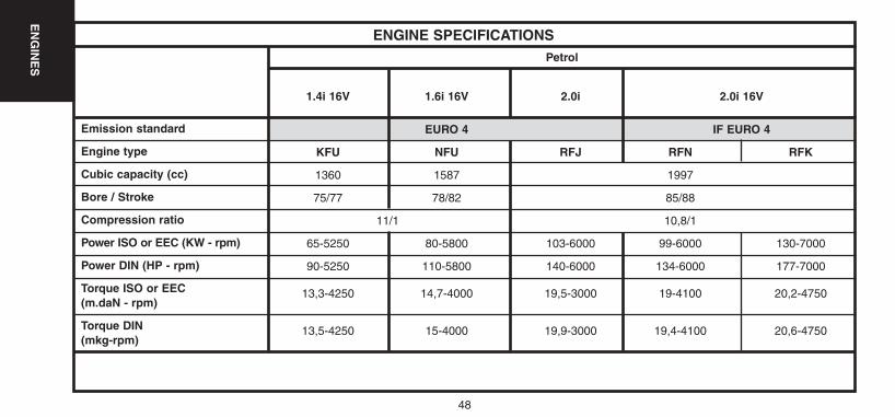
ENGINE SPECIFICATIONSPetrol
Emission standard
Engine type
Cubic capacity (cc)
Bore / Stroke
Compression ratio
Power ISO or EEC (KW - rpm)
Power DIN (HP - rpm)
Torque ISO or EEC(m.daN - rpm)
Torque DIN(mkg-rpm)
1.4i 16V 1.6i 16V 2.0i 2.0i 16V
EURO 4 IF EURO 4
KFU NFU RFJ RFN RFK
1360 1587 1997
75/77 78/82 85/88
11/1 10,8/1
65-5250 80-5800 103-6000 99-6000 130-7000
90-5250 110-5800 140-6000 134-6000 177-7000
13,3-4250 14,7-4000 19,5-3000 19-4100 20,2-4750
13,5-4250 15-4000 19,9-3000 19,4-4100 20,6-4750
48
EN
GIN
ES
UK-C4-page048-130-2004 15/11/04 9:23 Page 48
48
EN
GIN
ES
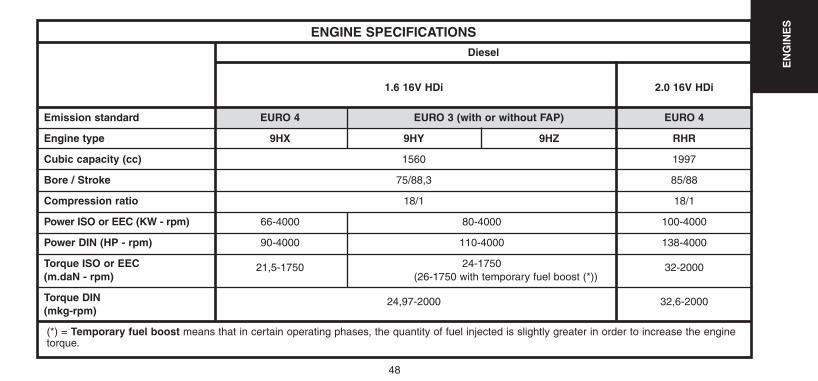
ENGINE SPECIFICATIONSDiesel
Emission standard
Engine type
Cubic capacity (cc)
Bore / Stroke
Compression ratio
Power ISO or EEC (KW - rpm)
Power DIN (HP - rpm)
Torque ISO or EEC(m.daN - rpm)
Torque DIN(mkg-rpm)
1.6 16V HDi 2.0 16V HDi
EURO 4 EURO 3 (with or without FAP) EURO 4
9HX 9HY 9HZ RHR
1560 1997
75/88,3 85/88
18/1 18/1
66-4000 80-4000 100-4000
90-4000 110-4000 138-4000
21,5-1750 24-1750 32-2000(26-1750 with temporary fuel boost (*))
24,97-2000 32,6-2000
(*) = Temporary fuel boost means that in certain operating phases, the quantity of fuel injected is slightly greater in order to increase the enginetorque.
UK-C4-page048-130-2004 15/11/04 9:23 Page 49
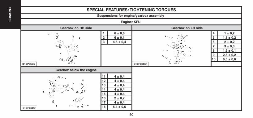
Gearbox below the engine
SPECIAL FEATURES: TIGHTENING TORQUES
1 6 ± 0,62 6 ± 0,13 4,5 ± 0,4
11 4 ± 0,412 4 ± 0,413 4 ± 0,414 4 ± 0,415 4 ± 0,416 2 ± 0,217 4 ± 0,418 5,4 ± 0,5
B1BP36BD
Suspensions for engine/gearbox assembly
50
EN
GIN
ES
Engine: KFU
Gearbox on RH side Gearbox on LH side
B1BP36DD
B1BP36CD
4 1 ± 0,25 1,8 ± 0,26 2 ± 0,27 3 ± 0,38 1,9 ± 0,19 2,5 ± 0,210 6,5 ± 0,6
UK-C4-page048-130-2004 15/11/04 9:23 Page 50
51
EN
GIN
ES
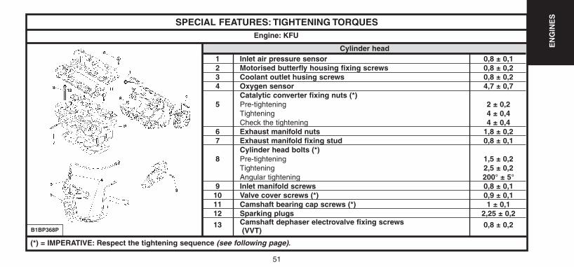
SPECIAL FEATURES: TIGHTENING TORQUES
Cylinder head1 Inlet air pressure sensor 0,8 ± 0,12 Motorised butterfly housing fixing screws 0,8 ± 0,23 Coolant outlet husing screws 0,8 ± 0,24 Oxygen sensor 4,7 ± 0,7
Catalytic converter fixing nuts (*)5 Pre-tightening 2 ± 0,2
Tightening 4 ± 0,4Check the tightening 4 ± 0,4
6 Exhaust manifold nuts 1,8 ± 0,27 Exhaust manifold fixing stud 0,8 ± 0,1
Cylinder head bolts (*)8 Pre-tightening 1,5 ± 0,2
Tightening 2,5 ± 0,2Angular tightening 200° ± 5°
9 Inlet manifold screws 0,8 ± 0,110 Valve cover screws (*) 0,9 ± 0,111 Camshaft bearing cap screws (*) 1 ± 0,112 Sparking plugs 2,25 ± 0,2
13 Camshaft dephaser electrovalve fixing screws 0,8 ± 0,2(VVT)
Engine: KFU
B1BP368P
(*) = IMPERATIVE: Respect the tightening sequence (see following page).
UK-C4-page048-130-2004 15/11/04 9:23 Page 51
52
EN
GIN
ES
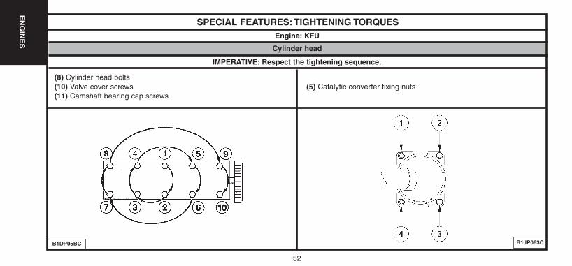
SPECIAL FEATURES: TIGHTENING TORQUESEngine: KFU
B1JP063CB1DP05BC
IMPERATIVE: Respect the tightening sequence.
Cylinder head
(8) Cylinder head bolts(10) Valve cover screws (5) Catalytic converter fixing nuts(11) Camshaft bearing cap screws
UK-C4-page048-130-2004 15/11/04 9:23 Page 52
53
EN
GIN
ES
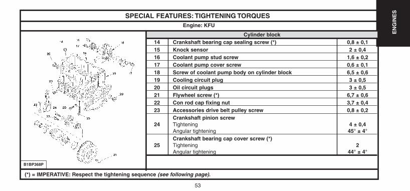
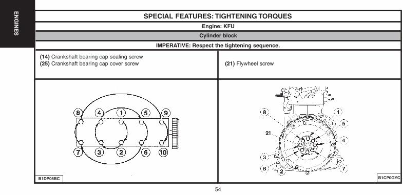
SPECIAL FEATURES: TIGHTENING TORQUES
Cylinder block14 Crankshaft bearing cap sealing screw (*) 0,8 ± 0,115 Knock sensor 2 ± 0,416 Coolant pump stud screw 1,6 ± 0,217 Coolant pump cover screw 0,6 ± 0,118 Screw of coolant pump body on cylinder block 6,5 ± 0,619 Cooling circuit plug 3 ± 0,520 Oil circuit plugs 3 ± 0,521 Flywheel screw (*) 6,7 ± 0,622 Con rod cap fixing nut 3,7 ± 0,423 Accessories drive belt pulley screw 0,8 ± 0,2
Crankshaft pinion screw24 Tightening 4 ± 0,4
Angular tightening 45° ± 4°Crankshaft bearing cap cover screw (*)
25 Tightening 2Angular tightening 44° ± 4°
Engine: KFU
B1BP368P
(*) = IMPERATIVE: Respect the tightening sequence (see following page).
UK-C4-page048-130-2004 15/11/04 9:23 Page 53
54
EN
GIN
ES
SPECIAL FEATURES: TIGHTENING TORQUESEngine: KFU
B1CP0GYCB1DP05BC
IMPERATIVE: Respect the tightening sequence.
Cylinder block
(14) Crankshaft bearing cap sealing screw(25) Crankshaft bearing cap cover screw (21) Flywheel screw
UK-C4-page048-130-2004 15/11/04 9:23 Page 54
55
EN
GIN
ES
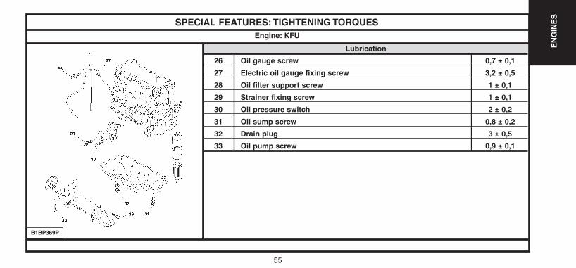
SPECIAL FEATURES: TIGHTENING TORQUES
Lubrication
26 Oil gauge screw 0,7 ± 0,1
27 Electric oil gauge fixing screw 3,2 ± 0,5
28 Oil filter support screw 1 ± 0,1
29 Strainer fixing screw 1 ± 0,1
30 Oil pressure switch 2 ± 0,2
31 Oil sump screw 0,8 ± 0,2
32 Drain plug 3 ± 0,5
33 Oil pump screw 0,9 ± 0,1
Engine: KFU
B1BP369P
UK-C4-page048-130-2004 15/11/04 9:23 Page 55
56
EN
GIN
ES
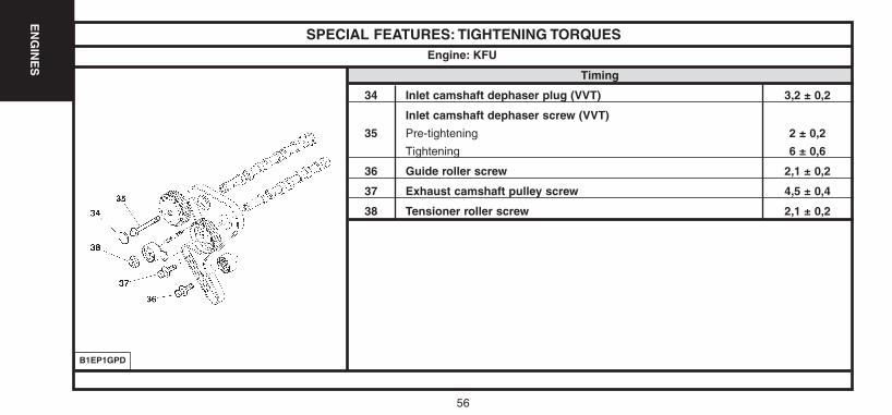
SPECIAL FEATURES: TIGHTENING TORQUES
Timing
34 Inlet camshaft dephaser plug (VVT) 3,2 ± 0,2
Inlet camshaft dephaser screw (VVT)
35 Pre-tightening 2 ± 0,2
Tightening 6 ± 0,6
36 Guide roller screw 2,1 ± 0,2
37 Exhaust camshaft pulley screw 4,5 ± 0,4
38 Tensioner roller screw 2,1 ± 0,2
Engine: KFU
B1EP1GPD
UK-C4-page048-130-2004 15/11/04 9:23 Page 56
57
EN
GIN
ES
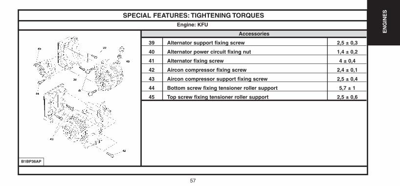
SPECIAL FEATURES: TIGHTENING TORQUES
Accessories
39 Alternator support fixing screw 2,5 ± 0,3
40 Alternator power circuit fixing nut 1,4 ± 0,2
41 Alternator fixing screw 4 ± 0,4
42 Aircon compressor fixing screw 2,4 ± 0,1
43 Aircon compressor support fixing screw 2,5 ± 0,4
44 Bottom screw fixing tensioner roller support 5,7 ± 1
45 Top screw fixing tensioner roller support 2,5 ± 0,6
Engine: KFU
B1BP36AP
UK-C4-page048-130-2004 15/11/04 9:23 Page 57
58
EN
GIN
ES
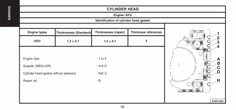
CYLINDER HEADEngine: KFU
Identification of cylinder head gasket
Engine types
KFU
Thicknesses (Standard)
1,2 ± 0,1
Thicknesses (repair)
1,5 ± 0,1
Thickness references
3
Engine type : 1 to 4
Supplier (MEILLOR) : A B D
Cylinder head gasket without asbestos : Ref. C
Repair ref. : R
B1BP10KC
UK-C4-page048-130-2004 15/11/04 9:23 Page 58
59
EN
GIN
ES
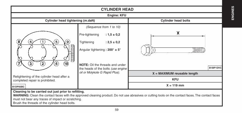
CYLINDER HEADEngine: KFU
Cylinder head tightening (m.daN) Cylinder head bolts
X = MAXIMUM reusable length
(Sequence from 1 to 10)
Pre-tightening : 1,5 ± 0,2
Tightening : 2,5 ± 0,2
Angular tightening : 200° ± 5°
NOTE: Oil the threads and underthe heads of the bolts (use engineoil or Molykote G Rapid Plus).
B1BP1DVC
B1DP05BC
Retightening of the cylinder head after acompleted repair is prohibited.
Cleaning to be carried out just prior to refitting.WARNING: Clean the contact faces with the approved cleaning product. Do not use abrasives or cutting tools on the contact faces. The contact facesmust not bear any traces of impact or scratching.Brush the threads of the cylinder head bolts.
KFU
X = 119 mm
UK-C4-page048-130-2004 15/11/04 9:23 Page 59
60
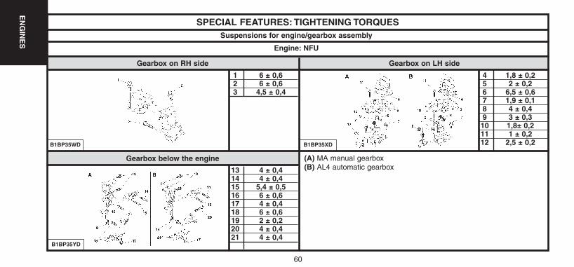
Gearbox below the engine
SPECIAL FEATURES: TIGHTENING TORQUES
1 6 ± 0,62 6 ± 0,63 4,5 ± 0,4
13 4 ± 0,414 4 ± 0,415 5,4 ± 0,516 6 ± 0,617 4 ± 0,418 6 ± 0,619 2 ± 0,220 4 ± 0,421 4 ± 0,4
B1BP35WD
Suspensions for engine/gearbox assembly
Engine: NFU
Gearbox on RH side Gearbox on LH side
B1BP35YD
B1BP35XD
4 1,8 ± 0,25 2 ± 0,26 6,5 ± 0,67 1,9 ± 0,18 4 ± 0,49 3 ± 0,310 1,8± 0,211 1 ± 0,212 2,5 ± 0,2
(A) MA manual gearbox(B) AL4 automatic gearbox
EN
GIN
ES
UK-C4-page048-130-2004 15/11/04 9:23 Page 60
61
EN
GIN
ES
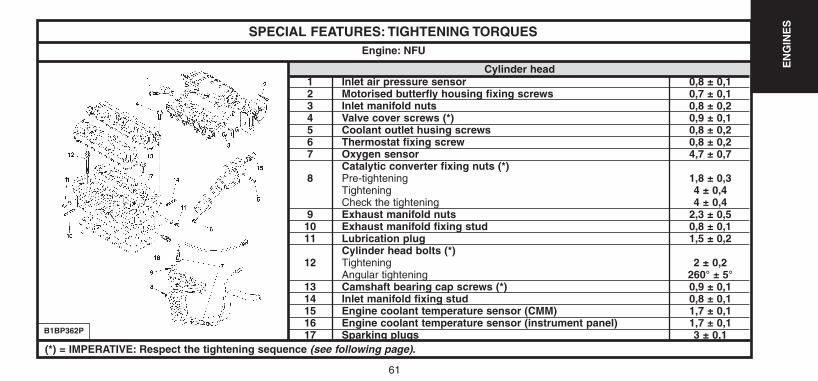
SPECIAL FEATURES: TIGHTENING TORQUES
Cylinder head1 Inlet air pressure sensor 0,8 ± 0,12 Motorised butterfly housing fixing screws 0,7 ± 0,13 Inlet manifold nuts 0,8 ± 0,24 Valve cover screws (*) 0,9 ± 0,15 Coolant outlet husing screws 0,8 ± 0,26 Thermostat fixing screw 0,8 ± 0,27 Oxygen sensor 4,7 ± 0,7
Catalytic converter fixing nuts (*)8 Pre-tightening 1,8 ± 0,3
Tightening 4 ± 0,4Check the tightening 4 ± 0,4
9 Exhaust manifold nuts 2,3 ± 0,510 Exhaust manifold fixing stud 0,8 ± 0,111 Lubrication plug 1,5 ± 0,2
Cylinder head bolts (*)12 Tightening 2 ± 0,2
Angular tightening 260° ± 5°13 Camshaft bearing cap screws (*) 0,9 ± 0,114 Inlet manifold fixing stud 0,8 ± 0,115 Engine coolant temperature sensor (CMM) 1,7 ± 0,116 Engine coolant temperature sensor (instrument panel) 1,7 ± 0,117 Sparking plugs 3 ± 0,1
Engine: NFU
B1BP362P
(*) = IMPERATIVE: Respect the tightening sequence (see following page).
UK-C4-page048-130-2004 15/11/04 9:23 Page 61
62
EN
GIN
ES
SPECIAL FEATURES: TIGHTENING TORQUES
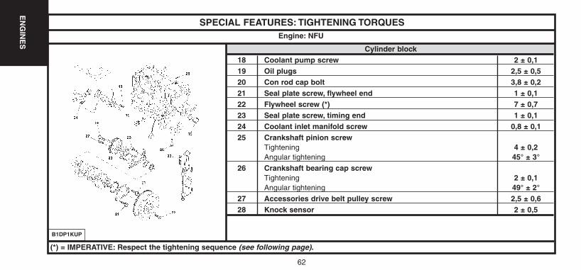
Cylinder block18 Coolant pump screw 2 ± 0,119 Oil plugs 2,5 ± 0,520 Con rod cap bolt 3,8 ± 0,221 Seal plate screw, flywheel end 1 ± 0,122 Flywheel screw (*) 7 ± 0,723 Seal plate screw, timing end 1 ± 0,124 Coolant inlet manifold screw 0,8 ± 0,125 Crankshaft pinion screw
Tightening 4 ± 0,2Angular tightening 45° ± 3°
26 Crankshaft bearing cap screwTightening 2 ± 0,1Angular tightening 49° ± 2°
27 Accessories drive belt pulley screw 2,5 ± 0,628 Knock sensor 2 ± 0,5
Engine: NFU
B1DP1KUP
(*) = IMPERATIVE: Respect the tightening sequence (see following page).
UK-C4-page048-130-2004 15/11/04 9:23 Page 62
63
EN
GIN
ES
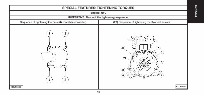
SPECIAL FEATURES: TIGHTENING TORQUESEngine: NFU
B1CP0GCCB1JP063C
Sequence of tightening the nuts (8) (Catalytic converter) (22) Sequence of tightening the flywheel screws
IMPERATIVE: Respect the tightening sequence.
UK-C4-page048-130-2004 15/11/04 9:23 Page 63
64
EN
GIN
ES
SPECIAL FEATURES: TIGHTENING TORQUES
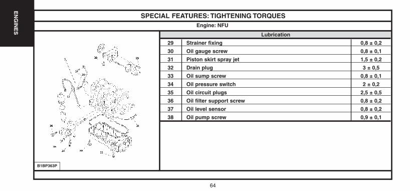
Lubrication
29 Strainer fixing 0,8 ± 0,2
30 Oil gauge screw 0,8 ± 0,1
31 Piston skirt spray jet 1,5 ± 0,2
32 Drain plug 3 ± 0,5
33 Oil sump screw 0,8 ± 0,1
34 Oil pressure switch 2 ± 0,2
35 Oil circuit plugs 2,5 ± 0,5
36 Oil filter support screw 0,8 ± 0,2
37 Oil level sensor 0,8 ± 0,2
38 Oil pump screw 0,9 ± 0,1
Engine: NFU
B1BP363P
UK-C4-page048-130-2004 15/11/04 9:23 Page 64
65
EN
GIN
ES
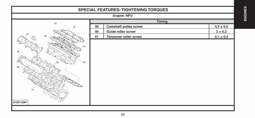
SPECIAL FEATURES: TIGHTENING TORQUES
Timing
39 Camshaft pulley screw 4,5 ± 0,5
40 Guide roller screw 2 ± 0,2
41 Tensioner roller screw 2,1 ± 0,4
Engine: NFU
B1BP1GMP
UK-C4-page048-130-2004 15/11/04 9:23 Page 65
66
EN
GIN
ES
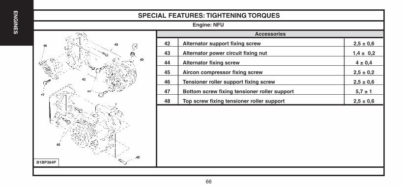
SPECIAL FEATURES: TIGHTENING TORQUES
Accessories
42 Alternator support fixing screw 2,5 ± 0,6
43 Alternator power circuit fixing nut 1,4 ± 0,2
44 Alternator fixing screw 4 ± 0,4
45 Aircon compressor fixing screw 2,5 ± 0,2
46 Tensioner roller support fixing screw 2,5 ± 0,6
47 Bottom screw fixing tensioner roller support 5,7 ± 1
48 Top screw fixing tensioner roller support 2,5 ± 0,6
Engine: NFU
B1BP364P
UK-C4-page048-130-2004 15/11/04 9:23 Page 66
67
EN
GIN
ES
67
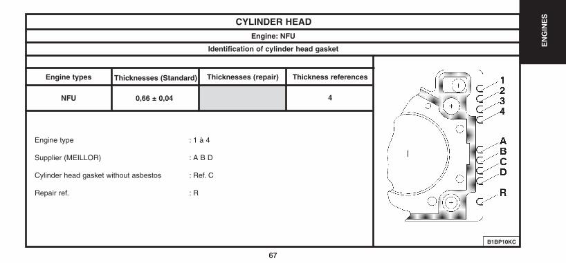
CYLINDER HEADEngine: NFU
Identification of cylinder head gasket
Engine types
NFU
Thicknesses (Standard)
0,66 ± 0,04
Thicknesses (repair) Thickness references
4
Engine type : 1 à 4
Supplier (MEILLOR) : A B D
Cylinder head gasket without asbestos : Ref. C
Repair ref. : R
B1BP10KC
UK-C4-page048-130-2004 15/11/04 9:23 Page 67
68
EN
GIN
ES
CYLINDER HEADEngine: NFU
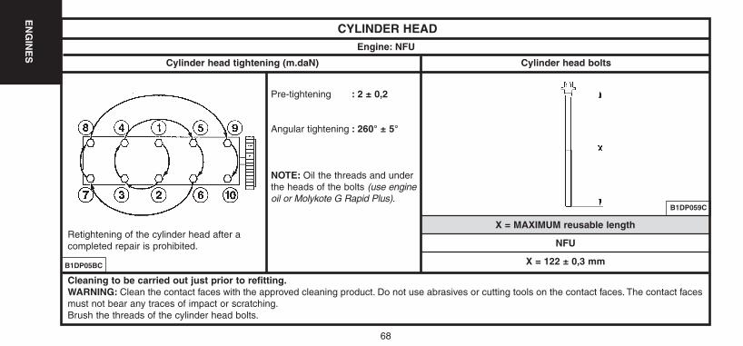
Cylinder head tightening (m.daN) Cylinder head bolts
X = MAXIMUM reusable length
Pre-tightening : 2 ± 0,2
Angular tightening : 260° ± 5°
NOTE: Oil the threads and underthe heads of the bolts (use engineoil or Molykote G Rapid Plus).
B1DP059C
B1DP05BC
Retightening of the cylinder head after acompleted repair is prohibited.
Cleaning to be carried out just prior to refitting.WARNING: Clean the contact faces with the approved cleaning product. Do not use abrasives or cutting tools on the contact faces. The contact facesmust not bear any traces of impact or scratching.Brush the threads of the cylinder head bolts.
NFU
X = 122 ± 0,3 mm
UK-C4-page048-130-2004 15/11/04 9:23 Page 68
69
EN
GIN
ES
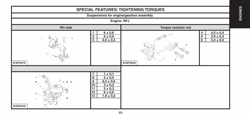
SPECIAL FEATURES: TIGHTENING TORQUES
1 6 ± 0,62 6 ± 0,63 4,5 ± 0,4
7 1 ± 0,18 5 ± 0,59 6,5 ± 0,610 3 ± 0,311 3 ± 0,312 6 ± 0,613 1,9 ± 0,2
B1BP35TD
Suspensions for engine/gearbox assembly
Engine: RFJ
RH side Torque reaction rod
B1BP35VD
B1BP35UD
4 4,5 ± 0,45 3,9 ± 0,46 5,4 ± 0,6
UK-C4-page048-130-2004 15/11/04 9:23 Page 69

70
EN
GIN
ES
SPECIAL FEATURES: TIGHTENING TORQUES
Cylinder headValve cover screws (*)
1 Pre-tightening 0,5Tightening 1,1 ± 0,1
2 Oxygen sensor 4,7 ± 0,53 Exhaust manifold nuts 3,5 ± 0,34 Coolant outlet housing fixing nuts 1 ± 0,15 Coolant outlet housing bolts 0,36 Motorised butterfly housing fixing screws 0,8 ± 0,17 Inlet manifold fixings 2,2 ± 0,48 Inlet manifold fixing studs 0,8 ± 0,2
Cylinder head bolts (*)Pre-tightening 1 1,5 ± 0,1Pre-tightening 2 5 ± 0,5
9 Angular tightening 360°Tightening 2 ± 0,2Angular tightening 285° ± 5°
10 Sparking plugs 2,7 ± 0,2
Engine: RFJ
B1BP35MP
(*) = IMPERATIVE: Respect the tightening sequence (see following page).
UK-C4-page048-130-2004 15/11/04 9:23 Page 70
71
EN
GIN
ES
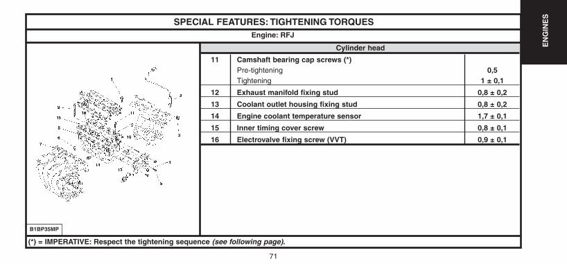
SPECIAL FEATURES: TIGHTENING TORQUES
Cylinder head
11 Camshaft bearing cap screws (*)Pre-tightening 0,5Tightening 1 ± 0,1
12 Exhaust manifold fixing stud 0,8 ± 0,2
13 Coolant outlet housing fixing stud 0,8 ± 0,2
14 Engine coolant temperature sensor 1,7 ± 0,1
15 Inner timing cover screw 0,8 ± 0,1
16 Electrovalve fixing screw (VVT) 0,9 ± 0,1
Engine: RFJ
B1BP35MP
(*) = IMPERATIVE: Respect the tightening sequence (see following page).
UK-C4-page048-130-2004 15/11/04 9:23 Page 71

72
EN
GIN
ES
SPECIAL FEATURES: TIGHTENING TORQUESEngine: RFJ
B1DP03XDB1DP05BC
IMPERATIVE: Respect the tightening sequence.
Cylinder head
(1) Valve cover screws(9) Cylinder head bolts (11) Camshaft bearing cap screws
UK-C4-page048-130-2004 15/11/04 9:23 Page 72
73
EN
GIN
ES
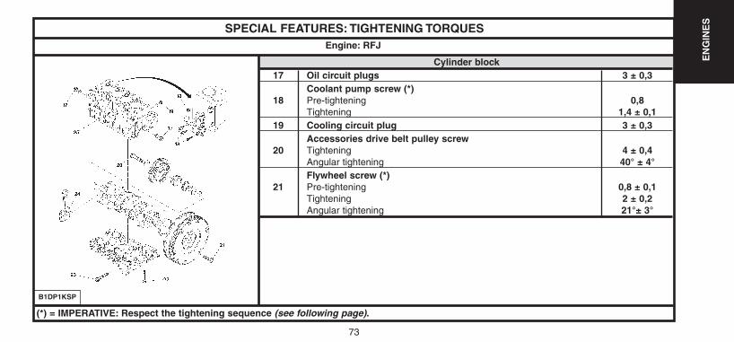
SPECIAL FEATURES: TIGHTENING TORQUES
Cylinder block17 Oil circuit plugs 3 ± 0,3
Coolant pump screw (*)18 Pre-tightening 0,8
Tightening 1,4 ± 0,119 Cooling circuit plug 3 ± 0,3
Accessories drive belt pulley screw20 Tightening 4 ± 0,4
Angular tightening 40° ± 4°Flywheel screw (*)
21 Pre-tightening 0,8 ± 0,1Tightening 2 ± 0,2Angular tightening 21°± 3°
Engine: RFJ
B1DP1KSP
(*) = IMPERATIVE: Respect the tightening sequence (see following page).
UK-C4-page048-130-2004 15/11/04 9:23 Page 73
74
EN
GIN
ES
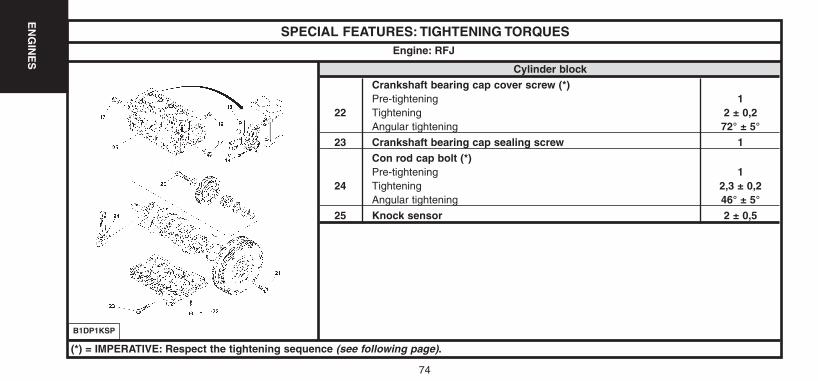
SPECIAL FEATURES: TIGHTENING TORQUES
Cylinder blockCrankshaft bearing cap cover screw (*)Pre-tightening 1
22 Tightening 2 ± 0,2Angular tightening 72° ± 5°
23 Crankshaft bearing cap sealing screw 1 Con rod cap bolt (*)Pre-tightening 1
24 Tightening 2,3 ± 0,2Angular tightening 46° ± 5°
25 Knock sensor 2 ± 0,5
Engine: RFJ
B1DP1KSP
(*) = IMPERATIVE: Respect the tightening sequence (see following page).
UK-C4-page048-130-2004 15/11/04 9:23 Page 74
75
EN
GIN
ES
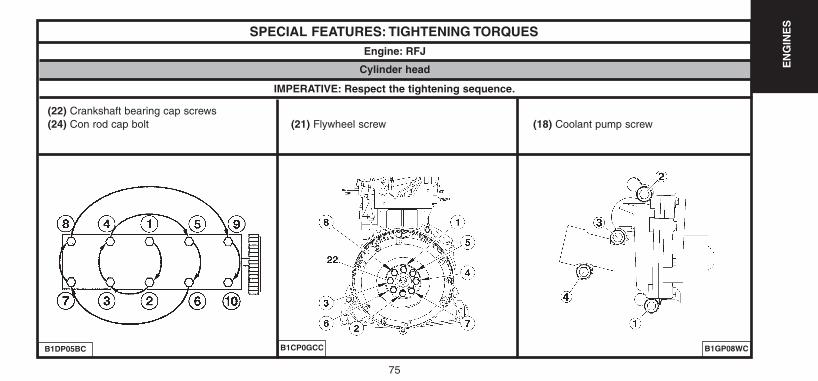
SPECIAL FEATURES: TIGHTENING TORQUESEngine: RFJ
B1GP08WCB1DP05BC
IMPERATIVE: Respect the tightening sequence.
Cylinder head
(22) Crankshaft bearing cap screws(24) Con rod cap bolt (21) Flywheel screw (18) Coolant pump screw
B1CP0GCC
UK-C4-page048-130-2004 15/11/04 9:23 Page 75

76
EN
GIN
ES
SPECIAL FEATURES: TIGHTENING TORQUES
Lubrication26 Oil gauge screw 1 ± 0,227 Oil filter support screw 0,8 ± 0,128 Anti-emulsion plate fixing screw 1,9 ± 0,329 Oil level sensor fixing screw 1 ± 0,230 Drain plug 3,4 ± 0,331 Oil sump screw 0,8 ± 0,132 Oil pressure switch 2 ± 0,233 Oil strainer fixing nuts 0,8 ± 0,134 Oil strainer stud 0,6 ± 0,1
Coolant pump screw35 Pre-tightening 0,7
Tightening 1 ± 0,1
Engine: RFJ
B1BP35NP
UK-C4-page048-130-2004 15/11/04 9:23 Page 76
77
EN
GIN
ES
SPECIAL FEATURES: TIGHTENING TORQUES
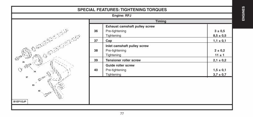
Timing
Exhaust camshaft pulley screw36 Pre-tightening 3 ± 0,5
Tightening 8,5 ± 0,5
37 Cap 1,1 ± 0,1
Inlet camshaft pulley screw38 Pre-tightening 2 ± 0,2
Tightening 11 ± 1
39 Tensioner roller screw 2,1 ± 0,2
Guide roller screw40 Pre-tightening 1,5 ± 0,1
Tightening 3,7 ± 0,7
Engine: RFJ
B1EP1GJP
UK-C4-page048-130-2004 15/11/04 9:23 Page 77
78
EN
GIN
ES
SPECIAL FEATURES: TIGHTENING TORQUES
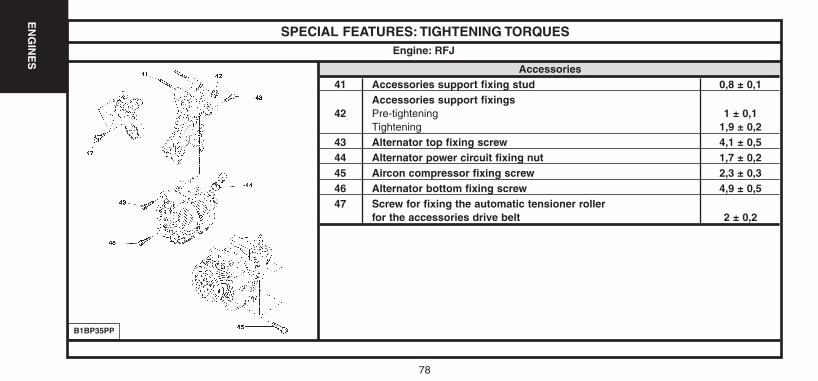
Accessories41 Accessories support fixing stud 0,8 ± 0,1
Accessories support fixings42 Pre-tightening 1 ± 0,1
Tightening 1,9 ± 0,243 Alternator top fixing screw 4,1 ± 0,544 Alternator power circuit fixing nut 1,7 ± 0,245 Aircon compressor fixing screw 2,3 ± 0,346 Alternator bottom fixing screw 4,9 ± 0,547 Screw for fixing the automatic tensioner roller
for the accessories drive belt 2 ± 0,2
Engine: RFJ
B1BP35PP
UK-C4-page048-130-2004 15/11/04 9:23 Page 78
79
EN
GIN
ES
CYLINDER HEADEngine: RFJ
B1DP1LPD
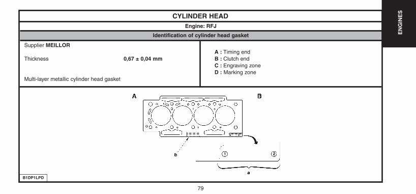
Identification of cylinder head gasket
Supplier MEILLORA : Timing end
Thickness 0,67 ± 0,04 mm B : Clutch endC : Engraving zoneD : Marking zone
Multi-layer metallic cylinder head gasket
UK-C4-page048-130-2004 15/11/04 9:23 Page 79
80
EN
GIN
ES
CYLINDER HEADEngine: RFJ
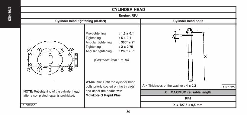
X = MAXIMUM reusable lengthNOTE: Retightening of the cylinder headafter a completed repair is prohibited.
Pre-tightening : 1,5 ± 0,1Tightening : 5 ± 0,1Angular tightening : 360° ± 2°Tightening : 2 ± 0,75Angular tightening : 285° ± 5°
(Sequence from 1 to 10)
WARNING: Refit the cylinder headbolts priorly coated on the threadsand under the heads withMolykote G Rapid Plus.
B1DP16FC
B1DP05BC
RFJ
X = 127,5 ± 0,5 mm
Cylinder head tightening (m.daN) Cylinder head bolts
A = Thickness of the washer : 4 ± 0,2
UK-C4-page048-130-2004 15/11/04 9:23 Page 80
81
EN
GIN
ES
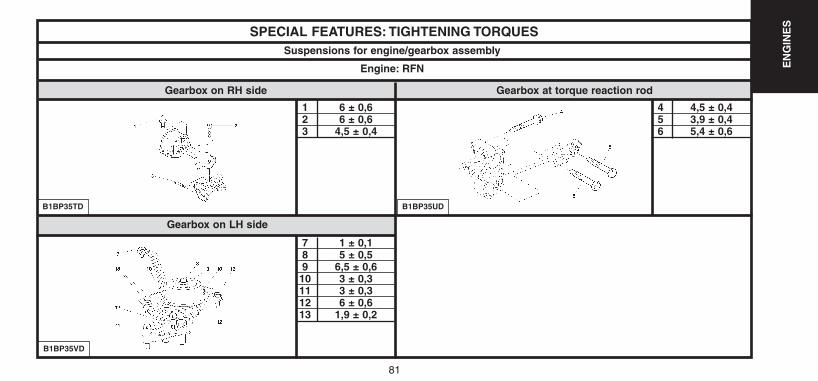
SPECIAL FEATURES: TIGHTENING TORQUES
1 6 ± 0,62 6 ± 0,63 4,5 ± 0,4
7 1 ± 0,18 5 ± 0,59 6,5 ± 0,610 3 ± 0,311 3 ± 0,312 6 ± 0,613 1,9 ± 0,2
B1BP35TD
Suspensions for engine/gearbox assembly
Engine: RFN
Gearbox on RH side Gearbox at torque reaction rod
B1BP35VD
B1BP35UD
4 4,5 ± 0,45 3,9 ± 0,46 5,4 ± 0,6
Gearbox on LH side
UK-C4-page048-130-2004 15/11/04 9:23 Page 81
82
EN
GIN
ES
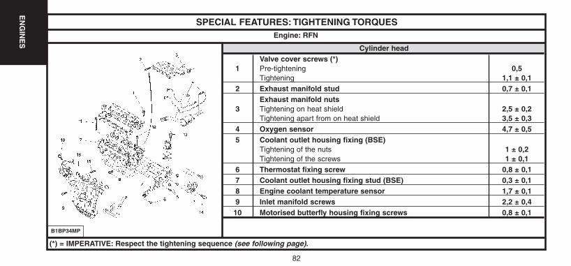
SPECIAL FEATURES: TIGHTENING TORQUES
Cylinder headValve cover screws (*)
1 Pre-tightening 0,5Tightening 1,1 ± 0,1
2 Exhaust manifold stud 0,7 ± 0,1Exhaust manifold nuts
3 Tightening on heat shield 2,5 ± 0,2Tightening apart from on heat shield 3,5 ± 0,3
4 Oxygen sensor 4,7 ± 0,55 Coolant outlet housing fixing (BSE)
Tightening of the nuts 1 ± 0,2Tightening of the screws 1 ± 0,1
6 Thermostat fixing screw 0,8 ± 0,17 Coolant outlet housing fixing stud (BSE) 0,3 ± 0,18 Engine coolant temperature sensor 1,7 ± 0,19 Inlet manifold screws 2,2 ± 0,410 Motorised butterfly housing fixing screws 0,8 ± 0,1
Engine: RFN
B1BP34MP
(*) = IMPERATIVE: Respect the tightening sequence (see following page).
UK-C4-page048-130-2004 15/11/04 9:23 Page 82
83
EN
GIN
ES
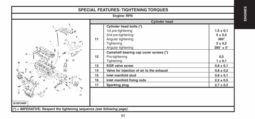
SPECIAL FEATURES: TIGHTENING TORQUES
Cylinder headCylinder head bolts (*)1st pre-tightening 1,5 ± 0,12nd pre-tightening 5 ± 0,5
11 Angular tightening 360°Tightening 2 ± 0,2Angular tightening 285° ± 5°Camshaft bearing cap cover screws (*)
12 Pre-tightening 0,5Tightening 1 ± 0,1
13 EGR valve screw 0,8 ± 0,114 Valve for injection of air to the exhaust 0,8 ± 0,215 Inlet manifold stud 0,8 ± 0,116 Inlet manifold fixing nuts 2,2 ± 0,517 Sparking plug 2,7 ± 0,2
Engine: RFN
B1BP34MP
(*) = IMPERATIVE: Respect the tightening sequence (see following page).
UK-C4-page048-130-2004 15/11/04 9:23 Page 83

EN
GIN
ES
84
SPECIAL FEATURES: TIGHTENING TORQUESEngine: RFN
B1DP03XDB1DP05BC
IMPERATIVE: Respect the tightening sequence.
Cylinder head
(1) Valve cover screws(11) Cylinder head bolts (12) Camshaft bearing cap screws
UK-C4-page048-130-2004 15/11/04 9:23 Page 84
85
EN
GIN
ES
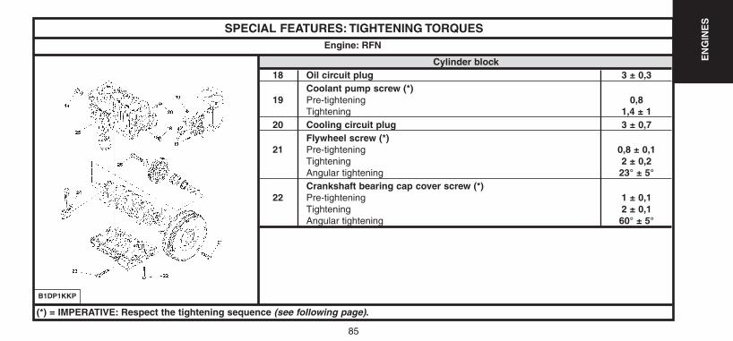
SPECIAL FEATURES: TIGHTENING TORQUES
Cylinder block18 Oil circuit plug 3 ± 0,3
Coolant pump screw (*)19 Pre-tightening 0,8
Tightening 1,4 ± 120 Cooling circuit plug 3 ± 0,7
Flywheel screw (*)21 Pre-tightening 0,8 ± 0,1
Tightening 2 ± 0,2Angular tightening 23° ± 5°Crankshaft bearing cap cover screw (*)
22 Pre-tightening 1 ± 0,1Tightening 2 ± 0,1Angular tightening 60° ± 5°
Engine: RFN
B1DP1KKP
(*) = IMPERATIVE: Respect the tightening sequence (see following page).
UK-C4-page048-130-2004 15/11/04 9:23 Page 85
86
EN
GIN
ES
86
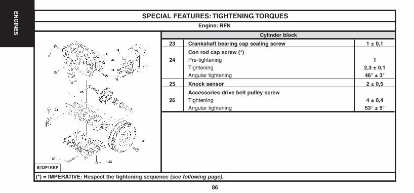
SPECIAL FEATURES: TIGHTENING TORQUES
Cylinder block
23 Crankshaft bearing cap sealing screw 1 ± 0,1
Con rod cap screw (*)24 Pre-tightening 1
Tightening 2,3 ± 0,1Angular tightening 46° ± 3°
25 Knock sensor 2 ± 0,5
Accessories drive belt pulley screw26 Tightening 4 ± 0,4
Angular tightening 53° ± 5°
Engine: RFN
B1DP1KKP
(*) = IMPERATIVE: Respect the tightening sequence (see following page).
UK-C4-page048-130-2004 15/11/04 9:23 Page 86

87
EN
GIN
ES
SPECIAL FEATURES: TIGHTENING TORQUESEngine: RFN
B1GP08WCB1DP05BC
IMPERATIVE: Respect the tightening sequence.
Cylinder head
(22) Crankshaft bearing cap screws(24) Con rod cap screws (21) Flywheel screws (19) Coolant pump screws
B1CP0GCC
UK-C4-page048-130-2004 15/11/04 9:23 Page 87
88
EN
GIN
ES
SPECIAL FEATURES: TIGHTENING TORQUES
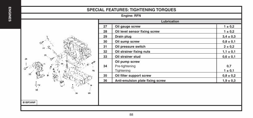
Lubrication
27 Oil gauge screw 1 ± 0,2
28 Oil level sensor fixing screw 1 ± 0,2
29 Drain plug 3,4 ± 0,3
30 Oil sump screw 0,8 ± 0,1
31 Oil pressure switch 2 ± 0,2
32 Oil strainer fixing nuts 1,1 ± 0,1
33 Oil strainer stud 0,6 ± 0,1
Oil pump screw34 Pre-tightening 0,7
Tightening 1 ± 0,1
35 Oil filter support screw 0,8 ± 0,2
36 Anti-emulsion plate fixing screw 1,9 ± 0,3
Engine: RFN
B1BP34NP
UK-C4-page048-130-2004 15/11/04 9:23 Page 88
89
EN
GIN
ES
SPECIAL FEATURES: TIGHTENING TORQUES
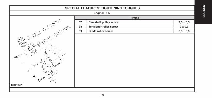
Timing
37 Camshaft pulley screw 7,5 ± 0,5
38 Tensioner roller screw 2 ± 0,3
39 Guide roller screw 3,5 ± 0,5
Engine: RFN
B1EP1G6P
UK-C4-page048-130-2004 15/11/04 9:23 Page 89

90
EN
GIN
ES
SPECIAL FEATURES: TIGHTENING TORQUES
Accessories40 Accessories support fixing stud 0,8 ± 0,1
Accessories support fixings41 Pre-tightening 1 ± 0,1
Tightening 1,9 ± 0,242 Alternator top fixing screw 4,1 ± 0,543 Alternator power circuit fixing nuts 1,7 ± 0,244 Aircon compressor fixing screw 2,3 ± 0,345 Alternator bottom fixing screw 4,9 ± 0,5
Screw for fixing the guide roller for the accessories drive belt46 Pre-tightening 1,5 ± 0,1
Tightening 3,5 ± 0,447 Screw for fixing the automatic tensioner roller
for the accessories drive belt 2 ± 0,2
Engine: RFN
B1BP34PP
UK-C4-page048-130-2004 15/11/04 9:23 Page 90
91
EN
GIN
ES
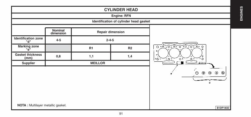
CYLINDER HEADEngine: RFN
Identification of cylinder head gasket
B1DP183D
Nominal dimension Repair dimension
2-4-54-5
R1 R2
1,1 1,40,8Gasket thickness(mm)
Supplier MEILLOR
Marking zone"e"
Identification zone"d"
NOTA : Multilayer metallic gasket.
UK-C4-page048-130-2004 15/11/04 9:23 Page 91
92
EN
GIN
ES
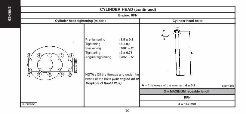
CYLINDER HEAD (continued)Engine: RFN
X = MAXIMUM reusable length
Pre-tightening : 1,5 ± 0,1Tightening : 5 ± 0,1Slackening : 360° ± 2°Tightening : 2 ± 0,75Angular tightening : 285° ± 5°
NOTA : Oil the threads and under theheads of the bolts (use engine oil orMolykote G Rapid Plus).
B1DP16FC
B1DP05BC
RFN
X = 147 mm
Cylinder head tightening (m.daN) Cylinder head bolts
A = Thickness of the washer : 4 ± 0,2
UK-C4-page048-130-2004 15/11/04 9:23 Page 92
93
EN
GIN
ES
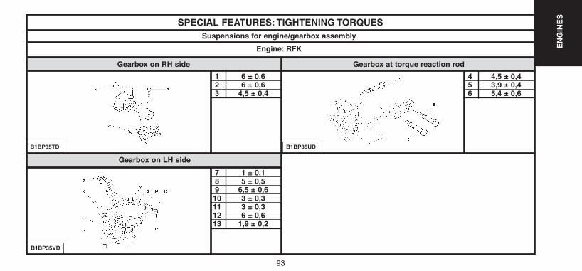
SPECIAL FEATURES: TIGHTENING TORQUES
1 6 ± 0,62 6 ± 0,63 4,5 ± 0,4
7 1 ± 0,18 5 ± 0,59 6,5 ± 0,610 3 ± 0,311 3 ± 0,312 6 ± 0,613 1,9 ± 0,2
B1BP35TD
Suspensions for engine/gearbox assembly
Engine: RFK
Gearbox on RH side Gearbox at torque reaction rod
B1BP35VD
B1BP35UD
4 4,5 ± 0,45 3,9 ± 0,46 5,4 ± 0,6
Gearbox on LH side
UK-C4-page048-130-2004 15/11/04 9:23 Page 93
94
EN
GIN
ES
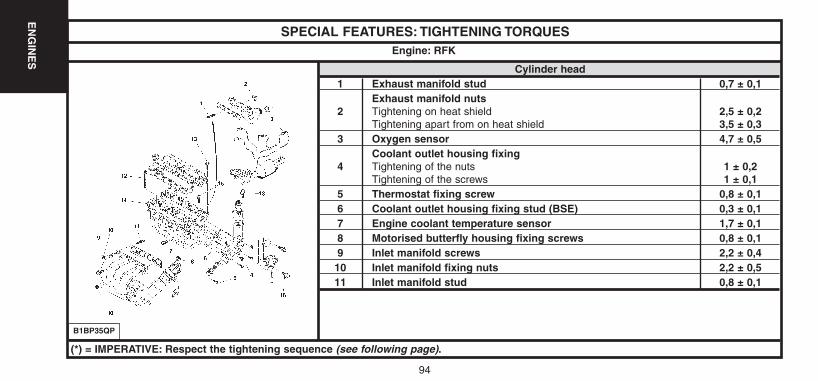
SPECIAL FEATURES: TIGHTENING TORQUES
Cylinder head1 Exhaust manifold stud 0,7 ± 0,1
Exhaust manifold nuts2 Tightening on heat shield 2,5 ± 0,2
Tightening apart from on heat shield 3,5 ± 0,33 Oxygen sensor 4,7 ± 0,5
Coolant outlet housing fixing4 Tightening of the nuts 1 ± 0,2
Tightening of the screws 1 ± 0,15 Thermostat fixing screw 0,8 ± 0,16 Coolant outlet housing fixing stud (BSE) 0,3 ± 0,17 Engine coolant temperature sensor 1,7 ± 0,18 Motorised butterfly housing fixing screws 0,8 ± 0,19 Inlet manifold screws 2,2 ± 0,410 Inlet manifold fixing nuts 2,2 ± 0,511 Inlet manifold stud 0,8 ± 0,1
Engine: RFK
B1BP35QP
(*) = IMPERATIVE: Respect the tightening sequence (see following page).
UK-C4-page048-130-2004 15/11/04 9:23 Page 94
95
EN
GIN
ES
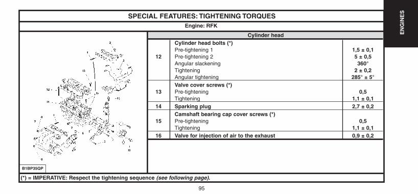
SPECIAL FEATURES: TIGHTENING TORQUES
Cylinder headCylinder head bolts (*)Pre-tightening 1 1,5 ± 0,1
12 Pre-tightening 2 5 ± 0,5Angular slackening 360°Tightening 2 ± 0,2Angular tightening 285° ± 5°Valve cover screws (*)
13 Pre-tightening 0,5Tightening 1,1 ± 0,1
14 Sparking plug 2,7 ± 0,2Camshaft bearing cap cover screws (*)
15 Pre-tightening 0,5Tightening 1,1 ± 0,1
16 Valve for injection of air to the exhaust 0,9 ± 0,2
Engine: RFK
B1BP35QP
(*) = IMPERATIVE: Respect the tightening sequence (see following page).
UK-C4-page048-130-2004 15/11/04 9:23 Page 95

96
EN
GIN
ES
SPECIAL FEATURES: TIGHTENING TORQUESEngine: RFK
B1DP03XDB1DP05BC
IMPERATIVE: Respect the tightening sequence.
Cylinder head
(12) Valve cover screws(13) Cylinder head bolts (15) Camshaft bearing cap screws
UK-C4-page048-130-2004 15/11/04 9:23 Page 96
97
EN
GIN
ES
97
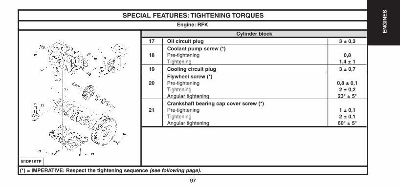
SPECIAL FEATURES: TIGHTENING TORQUES
Cylinder block17 Oil circuit plug 3 ± 0,3
Coolant pump screw (*)18 Pre-tightening 0,8
Tightening 1,4 ± 119 Cooling circuit plug 3 ± 0,7
Flywheel screw (*)20 Pre-tightening 0,8 ± 0,1
Tightening 2 ± 0,2Angular tightening 23° ± 5°Crankshaft bearing cap cover screw (*)
21 Pre-tightening 1 ± 0,1Tightening 2 ± 0,1Angular tightening 60° ± 5°
Engine: RFK
B1DP1KTP
(*) = IMPERATIVE: Respect the tightening sequence (see following page).
UK-C4-page048-130-2004 15/11/04 9:23 Page 97
98
EN
GIN
ES
SPECIAL FEATURES: TIGHTENING TORQUES
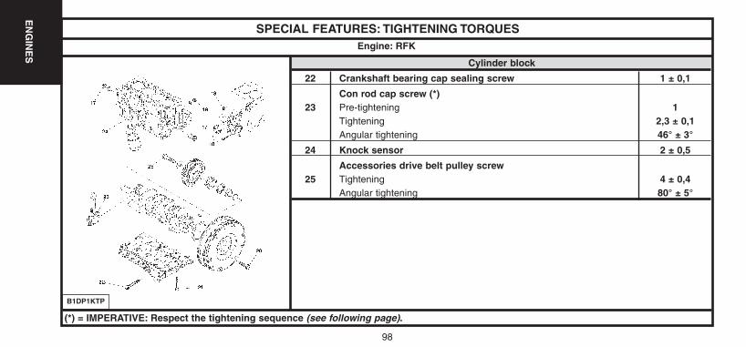
Cylinder block
22 Crankshaft bearing cap sealing screw 1 ± 0,1
Con rod cap screw (*)23 Pre-tightening 1
Tightening 2,3 ± 0,1Angular tightening 46° ± 3°
24 Knock sensor 2 ± 0,5
Accessories drive belt pulley screw25 Tightening 4 ± 0,4
Angular tightening 80° ± 5°
Engine: RFK
B1DP1KTP
(*) = IMPERATIVE: Respect the tightening sequence (see following page).
UK-C4-page048-130-2004 15/11/04 9:23 Page 98

99
EN
GIN
ES
99
SPECIAL FEATURES: TIGHTENING TORQUESEngine: RFK
B1GP08WCB1DP05BC
IMPERATIVE: Respect the tightening sequence.
Cylinder head
(21) Crankshaft bearing cap screws(23) Con rod cap screws (20) Flywheel screws (18) Coolant pump screws
B1CP0GCC
UK-C4-page048-130-2004 15/11/04 9:23 Page 99
100
EN
GIN
ES
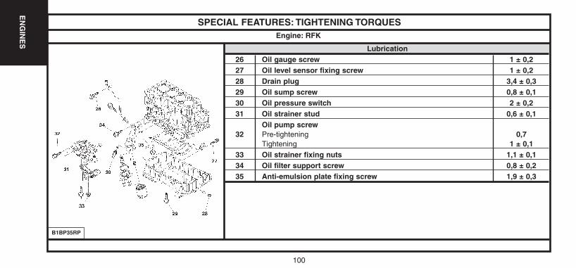
SPECIAL FEATURES: TIGHTENING TORQUES
Lubrication26 Oil gauge screw 1 ± 0,227 Oil level sensor fixing screw 1 ± 0,228 Drain plug 3,4 ± 0,329 Oil sump screw 0,8 ± 0,130 Oil pressure switch 2 ± 0,231 Oil strainer stud 0,6 ± 0,1
Oil pump screw32 Pre-tightening 0,7
Tightening 1 ± 0,133 Oil strainer fixing nuts 1,1 ± 0,134 Oil filter support screw 0,8 ± 0,235 Anti-emulsion plate fixing screw 1,9 ± 0,3
Engine: RFK
B1BP35RP
UK-C4-page048-130-2004 15/11/04 9:23 Page 100
101
EN
GIN
ES
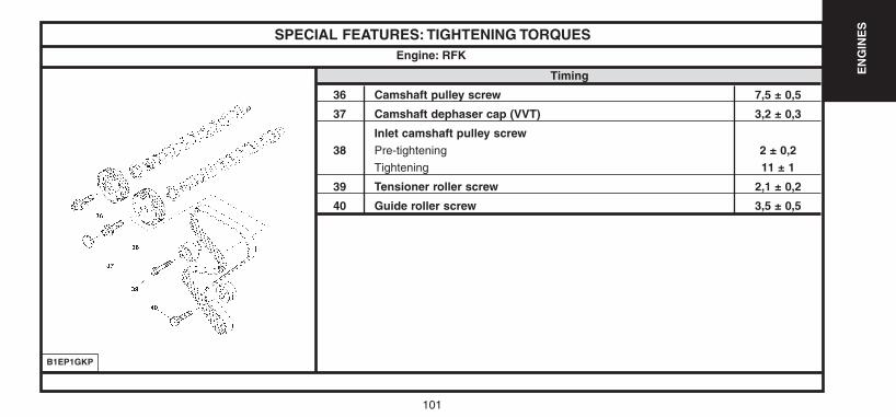
SPECIAL FEATURES: TIGHTENING TORQUES
Timing
36 Camshaft pulley screw 7,5 ± 0,5
37 Camshaft dephaser cap (VVT) 3,2 ± 0,3
Inlet camshaft pulley screw38 Pre-tightening 2 ± 0,2
Tightening 11 ± 1
39 Tensioner roller screw 2,1 ± 0,2
40 Guide roller screw 3,5 ± 0,5
Engine: RFK
B1EP1GKP
UK-C4-page048-130-2004 15/11/04 9:23 Page 101
102
EN
GIN
ES
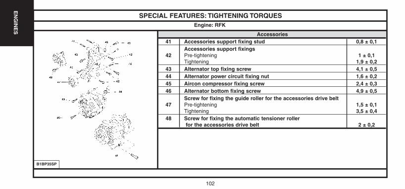
SPECIAL FEATURES: TIGHTENING TORQUES
Accessories41 Accessories support fixing stud 0,8 ± 0,1
Accessories support fixings42 Pre-tightening 1 ± 0,1
Tightening 1,9 ± 0,243 Alternator top fixing screw 4,1 ± 0,544 Alternator power circuit fixing nut 1,6 ± 0,245 Aircon compressor fixing screw 2,4 ± 0,346 Alternator bottom fixing screw 4,9 ± 0,5
Screw for fixing the guide roller for the accessories drive belt47 Pre-tightening 1,5 ± 0,1
Tightening 3,5 ± 0,448 Screw for fixing the automatic tensioner roller
for the accessories drive belt 2 ± 0,2
Engine: RFK
B1BP35SP
UK-C4-page048-130-2004 15/11/04 9:23 Page 102
103
EN
GIN
ES
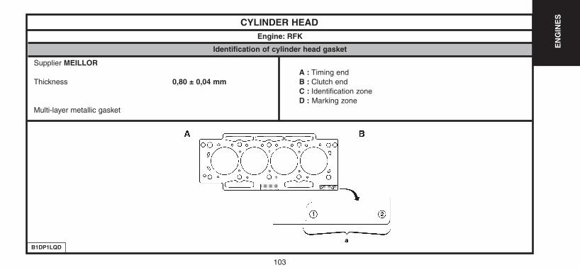
CYLINDER HEADEngine: RFK
B1DP1LQD
Identification of cylinder head gasket
Supplier MEILLORA : Timing end
Thickness 0,80 ± 0,04 mm B : Clutch endC : Identification zoneD : Marking zone
Multi-layer metallic gasket
UK-C4-page048-130-2004 15/11/04 9:23 Page 103
104
EN
GIN
ES
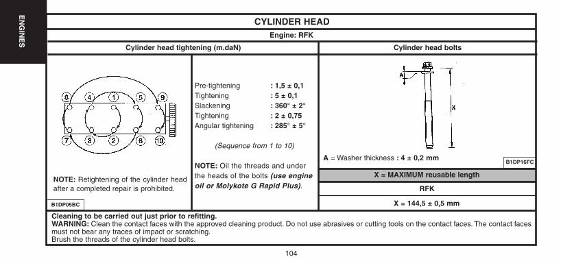
CYLINDER HEADEngine: RFK
X = MAXIMUM reusable lengthNOTE: Retightening of the cylinder headafter a completed repair is prohibited.
Pre-tightening : 1,5 ± 0,1Tightening : 5 ± 0,1Slackening : 360° ± 2°Tightening : 2 ± 0,75Angular tightening : 285° ± 5°
(Sequence from 1 to 10)
NOTE: Oil the threads and underthe heads of the bolts (use engineoil or Molykote G Rapid Plus).
B1DP16FC
B1DP05BC
RFK
X = 144,5 ± 0,5 mm
Cylinder head tightening (m.daN) Cylinder head bolts
A = Washer thickness : 4 ± 0,2 mm
Cleaning to be carried out just prior to refitting.WARNING: Clean the contact faces with the approved cleaning product. Do not use abrasives or cutting tools on the contact faces. The contact facesmust not bear any traces of impact or scratching.Brush the threads of the cylinder head bolts.
UK-C4-page048-130-2004 15/11/04 9:23 Page 104
105
EN
GIN
ES
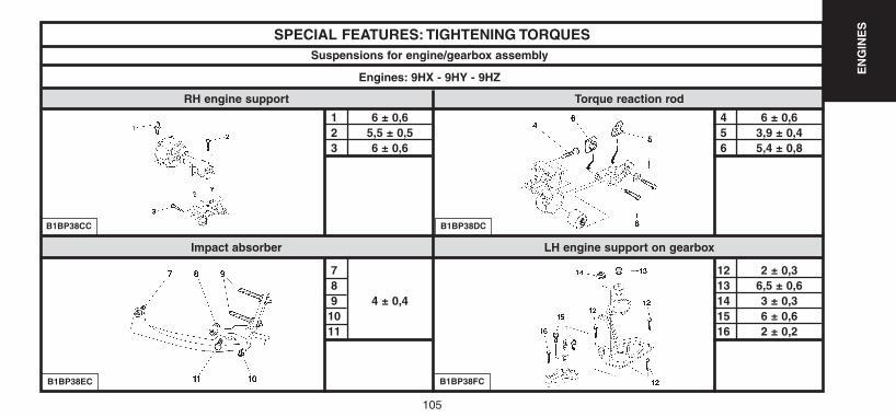
Impact absorber LH engine support on gearbox
SPECIAL FEATURES: TIGHTENING TORQUES
1 6 ± 0,62 5,5 ± 0,53 6 ± 0,6
789 4 ± 0,41011
B1BP38CC
Suspensions for engine/gearbox assembly
Engines: 9HX - 9HY - 9HZ
RH engine support Torque reaction rod
B1BP38EC
B1BP38DC
4 6 ± 0,65 3,9 ± 0,46 5,4 ± 0,8
12 2 ± 0,313 6,5 ± 0,614 3 ± 0,315 6 ± 0,616 2 ± 0,2
B1BP38FC
UK-C4-page048-130-2004 15/11/04 9:23 Page 105
106
EN
GIN
ES
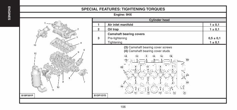
SPECIAL FEATURES: TIGHTENING TORQUES
Cylinder head
1 Air inlet manifold 1 ± 0,1
2 Oil trap 1 ± 0,1
Camshaft bearing covers3 Pre-tightening 0,5 ± 0,1
Tightening 1 ± 0,1
Engine: 9HX
B1BP39YP B1DP1D7D
(3) Camshaft bearing cover screws(4) Camshaft bearing cover studs
UK-C4-page048-130-2004 15/11/04 9:23 Page 106
107
EN
GIN
ES
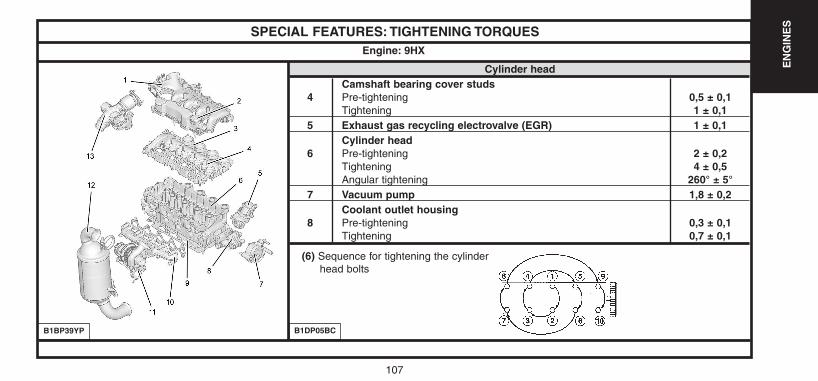
SPECIAL FEATURES: TIGHTENING TORQUES
Cylinder headCamshaft bearing cover studs
4 Pre-tightening 0,5 ± 0,1Tightening 1 ± 0,1
5 Exhaust gas recycling electrovalve (EGR) 1 ± 0,1Cylinder head
6 Pre-tightening 2 ± 0,2Tightening 4 ± 0,5Angular tightening 260° ± 5°
7 Vacuum pump 1,8 ± 0,2Coolant outlet housing
8 Pre-tightening 0,3 ± 0,1Tightening 0,7 ± 0,1
Engine: 9HX
B1DP05BC
(6) Sequence for tightening the cylinderhead bolts
B1BP39YP
UK-C4-page048-130-2004 15/11/04 9:23 Page 107
108
EN
GIN
ES
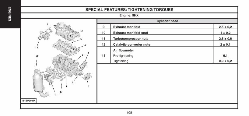
SPECIAL FEATURES: TIGHTENING TORQUES
Cylinder head
9 Exhaust manifold 2,5 ± 0,2
10 Exhaust manifold stud 1 ± 0,2
11 Turbocompressor nuts 2,6 ± 0,6
12 Catalytic converter nuts 2 ± 0,1
Air flowmeter
13 Pre-tightening 0,1
Tightening 0,9 ± 0,2
Engine: 9HX
B1BP39YP
UK-C4-page048-130-2004 15/11/04 9:23 Page 108
109
EN
GIN
ES
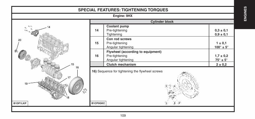
SPECIAL FEATURES: TIGHTENING TORQUES
Cylinder blockCoolant pump
14 Pre-tightening 0,3 ± 0,1Tightening 0,9 ± 0,1Con rod screws
15 Pre-tightening 1 ± 0,1Angular tightening 100° ± 5°Flywheel (according to equipment)
16 Pre-tightening 1,7 ± 0,2Angular tightening 75° ± 5°Clutch mechanism 2 ± 0,2
Engine: 9HX
B1DP1LKP B1CP0GKC
16) Sequence for tightening the flywheel screws
UK-C4-page048-130-2004 15/11/04 9:23 Page 109
110
EN
GIN
ES
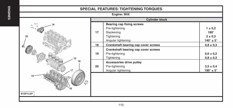
SPECIAL FEATURES: TIGHTENING TORQUES
Cylinder block
Bearing cap fixing screwsPre-tightening 1 ± 0,2
17 Slackening 180°Tightening 3 ± 0,3Angular tightening 140° ± 5°
18 Crankshaft bearing cap cover screws 0,8 ± 0,3
Crankshaft bearing cap cover screws19 Pre-tightening 0,6 ± 0,2
Tightening 0,8 ± 0,3
Accessories drive pulley20 Pre-tightening 3,5 ± 0,4
Angular tightening 190° ± 5°
Engine: 9HX
B1DP1LKP
UK-C4-page048-130-2004 15/11/04 9:23 Page 110
111
EN
GIN
ES
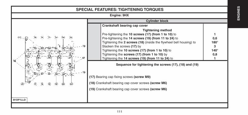
SPECIAL FEATURES: TIGHTENING TORQUES
Cylinder blockCrankshaft bearing cap cover
Tightening method Pre-tightening the 10 screws (17) (from 1 to 10) to 1Pre-tightening the 14 screws (19) (from 11 to 24) to 0,6Tightening the 2 screws (18) (inside the flywheel bell housing) to 180°Slacken the screws (17) by 3Tightening the 10 screws (17) (from 1 to 10) to 140°Tightening the screws (17) (from 1 to 10) by 0,8Tightening the 14 screws (19) (from 11 to 24) to 1
Engine: 9HX
B1DP1LLD
Sequence for tightening the screws (17), (18) and (19)
(17) Bearing cap fixing screws (screw M9)
(18) Crankshaft bearing cap cover screws (screw M6)
(19) Crankshaft bearing cap cover screws (screw M6)
UK-C4-page048-130-2004 15/11/04 9:23 Page 111
112
EN
GIN
ES
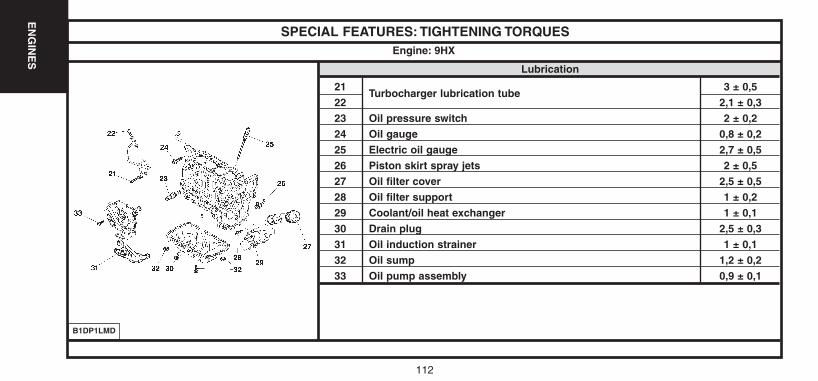
SPECIAL FEATURES: TIGHTENING TORQUES
Lubrication
21Turbocharger lubrication tube
3 ± 0,522 2,1 ± 0,323 Oil pressure switch 2 ± 0,224 Oil gauge 0,8 ± 0,225 Electric oil gauge 2,7 ± 0,526 Piston skirt spray jets 2 ± 0,527 Oil filter cover 2,5 ± 0,528 Oil filter support 1 ± 0,229 Coolant/oil heat exchanger 1 ± 0,130 Drain plug 2,5 ± 0,331 Oil induction strainer 1 ± 0,132 Oil sump 1,2 ± 0,233 Oil pump assembly 0,9 ± 0,1
Engine: 9HX
B1DP1LMD
UK-C4-page048-130-2004 15/11/04 9:23 Page 112
113
EN
GIN
ES
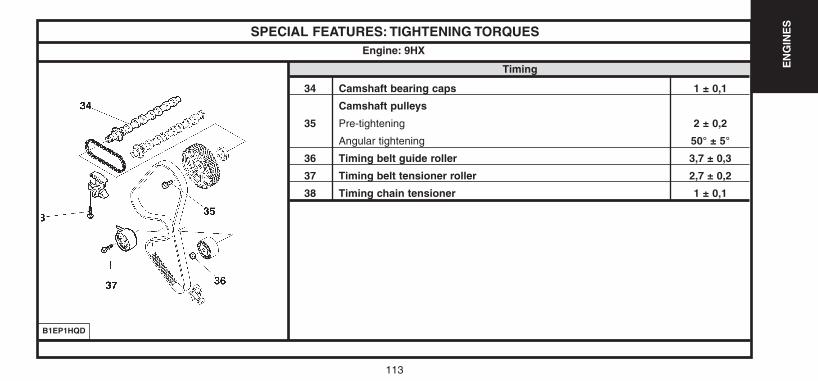
SPECIAL FEATURES: TIGHTENING TORQUES
Timing
34 Camshaft bearing caps 1 ± 0,1
Camshaft pulleys
35 Pre-tightening 2 ± 0,2
Angular tightening 50° ± 5°
36 Timing belt guide roller 3,7 ± 0,3
37 Timing belt tensioner roller 2,7 ± 0,2
38 Timing chain tensioner 1 ± 0,1
Engine: 9HX
B1EP1HQD
UK-C4-page048-130-2004 15/11/04 9:23 Page 113
114
EN
GIN
ES
SPECIAL FEATURES: TIGHTENING TORQUES
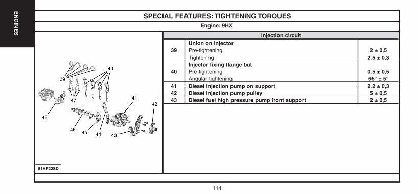
Injection circuit
Union on injector39 Pre-tightening 2 ± 0,5
Tightening 2,5 ± 0,3Injector fixing flange but
40 Pre-tightening 0,5 ± 0,5Angular tightening 65° ± 5°
41 Diesel injection pump on support 2,2 ± 0,342 Diesel injection pump pulley 5 ± 0,543 Diesel fuel high pressure pump front support 2 ± 0,5
Engine: 9HX
B1HP22SD
UK-C4-page048-130-2004 15/11/04 9:23 Page 114
115
EN
GIN
ES
SPECIAL FEATURES: TIGHTENING TORQUES
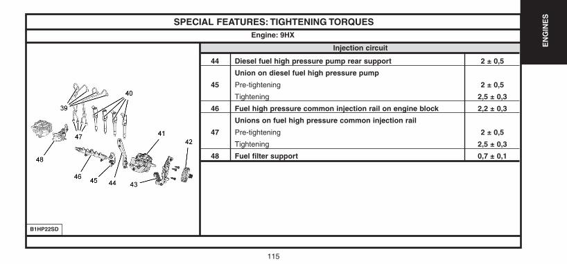
Injection circuit
44 Diesel fuel high pressure pump rear support 2 ± 0,5
Union on diesel fuel high pressure pump
45 Pre-tightening 2 ± 0,5
Tightening 2,5 ± 0,3
46 Fuel high pressure common injection rail on engine block 2,2 ± 0,3
Unions on fuel high pressure common injection rail
47 Pre-tightening 2 ± 0,5
Tightening 2,5 ± 0,3
48 Fuel filter support 0,7 ± 0,1
Engine: 9HX
B1HP22SD
UK-C4-page048-130-2004 15/11/04 9:23 Page 115
116
EN
GIN
ES
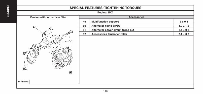
SPECIAL FEATURES: TIGHTENING TORQUES
Accessories
49 Multifunction support 2 ± 0,4
50 Alternator fixing screw 4,9 ± 1,2
51 Alternator power circuit fixing nut 1,4 ± 0,2
52 Accessories tensioner roller 2,1 ± 0,2
Engine: 9HX
D1AP02NC
Version without particle filter
UK-C4-page048-130-2004 15/11/04 9:23 Page 116
117
EN
GIN
ES
SPECIAL FEATURES: TIGHTENING TORQUES
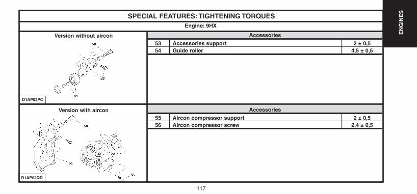
Accessories
53 Accessories support 2 ± 0,554 Guide roller 4,5 ± 0,5
Engine: 9HX
D1AP02PC
Version without aircon
D1AP02QD
Accessories
55 Aircon compressor support 2 ± 0,556 Aircon compressor screw 2,4 ± 0,5
Version with aircon
UK-C4-page048-130-2004 15/11/04 9:23 Page 117
118
EN
GIN
ES
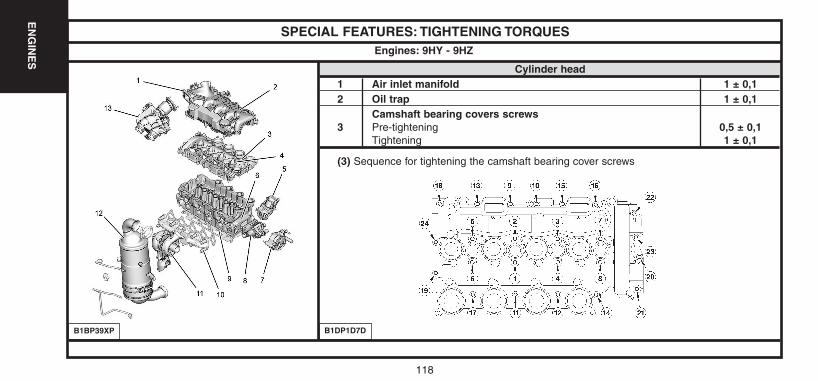
SPECIAL FEATURES: TIGHTENING TORQUES
Cylinder head1 Air inlet manifold 1 ± 0,12 Oil trap 1 ± 0,1
Camshaft bearing covers screws3 Pre-tightening 0,5 ± 0,1
Tightening 1 ± 0,1
Engines: 9HY - 9HZ
B1DP1D7D
(3) Sequence for tightening the camshaft bearing cover screws
B1BP39XP
UK-C4-page048-130-2004 15/11/04 9:23 Page 118
119
EN
GIN
ES
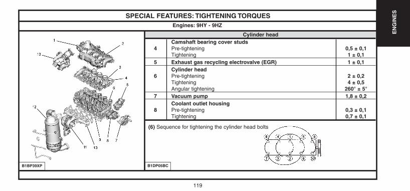
SPECIAL FEATURES: TIGHTENING TORQUES
Cylinder headCamshaft bearing cover studs
4 Pre-tightening 0,5 ± 0,1Tightening 1 ± 0,1
5 Exhaust gas recycling electrovalve (EGR) 1 ± 0,1Cylinder head
6 Pre-tightening 2 ± 0,2Tightening 4 ± 0,5Angular tightening 260° ± 5°
7 Vacuum pump 1,8 ± 0,2Coolant outlet housing
8 Pre-tightening 0,3 ± 0,1Tightening 0,7 ± 0,1
Engines: 9HY - 9HZ
B1DP05BC
(6) Sequence for tightening the cylinder head bolts
B1BP39XP
UK-C4-page048-130-2004 15/11/04 9:23 Page 119
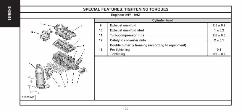
120
EN
GIN
ES
SPECIAL FEATURES: TIGHTENING TORQUES
Cylinder head
9 Exhaust manifold 2,5 ± 0,2
10 Exhaust manifold stud 1 ± 0,2
11 Turbocompressor nuts 2,6 ± 0,6
12 Catalytic converter nuts 2 ± 0,1
Double butterfly housing (according to equipment)13 Pre-tightening 0,1
Tightening 0,9 ± 0,2
Engines: 9HY - 9HZ
B1BP39XP
UK-C4-page048-130-2004 15/11/04 9:23 Page 120
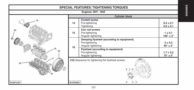
121
EN
GIN
ES
SPECIAL FEATURES: TIGHTENING TORQUES
Cylinder blockCoolant pump
14 Pre-tightening 0,3 ± 0,1Tightening 0,9 ± 0,1Con rod screws
15 Pre-tightening 1 ± 0,1Angular tightening 100° ± 5°Damping flywheel (according to equipment)Pre-tightening 3 ± 0,3
16Angular tightening 90° ± 5°Flywheel (according to equipment)Pre-tightening 1,7 ± 0,2Angular tightening 75° ± 5°
Engines: 9HY - 9HZ
B1DP1LKP B1CP0GKC
(16) Sequence for tightening the flywheel screws
UK-C4-page048-130-2004 15/11/04 9:23 Page 121

122
EN
GIN
ES
SPECIAL FEATURES: TIGHTENING TORQUES
Cylinder blockBearing cap fixing screwsPre-tightening 1 ± 0,2
17 Slackening 180°Tightening 3 ± 0,3Angular tightening 140° ± 5°
18 Crankshaft bearing cap cover screws 0,8 ± 0,3Crankshaft bearing cap cover screws
19 Pre-tightening 0,6 ± 0,2Tightening 0,8 ± 0,3Accessories drive pulley
20 Pre-tightening 3,5 ± 0,4Angular tightening 190° ± 5°
Engines: 9HY - 9HZ
B1DP1LKP
UK-C4-page048-130-2004 15/11/04 9:23 Page 122
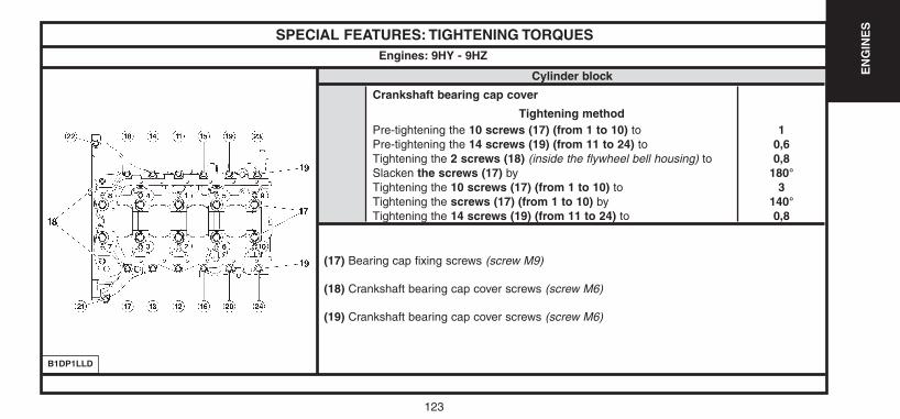
123
EN
GIN
ES
SPECIAL FEATURES: TIGHTENING TORQUES
Cylinder block
Crankshaft bearing cap cover
Tightening method Pre-tightening the 10 screws (17) (from 1 to 10) to 1Pre-tightening the 14 screws (19) (from 11 to 24) to 0,6Tightening the 2 screws (18) (inside the flywheel bell housing) to 0,8Slacken the screws (17) by 180°Tightening the 10 screws (17) (from 1 to 10) to 3Tightening the screws (17) (from 1 to 10) by 140°Tightening the 14 screws (19) (from 11 to 24) to 0,8
Engines: 9HY - 9HZ
B1DP1LLD
(17) Bearing cap fixing screws (screw M9)
(18) Crankshaft bearing cap cover screws (screw M6)
(19) Crankshaft bearing cap cover screws (screw M6)
UK-C4-page048-130-2004 15/11/04 9:23 Page 123

124
EN
GIN
ES
124
SPECIAL FEATURES: TIGHTENING TORQUES
Lubrication21
Turbocharger lubrication tube3 ± 0,5
22 2,1 ± 0,323 Oil pressure switch 2 ± 0,224 Oil gauge 0,8 ± 0,225 Oil level sensor 2,7 ± 0,526 Piston skirt spray jets 2 ± 0,527 Oil filter cover 2,5 ± 0,528 Oil filter support 1 ± 0,229 Coolant/oil heat exchanger 1 ± 0,130 Drain plug 2,5 ± 0,331 Oil induction strainer 1 ± 0,132 Oil sump 1,2 ± 0,233 Oil pump assembly 0,9 ± 0,1
Engines: 9HY - 9HZ
B1DP1LMD
UK-C4-page048-130-2004 15/11/04 9:23 Page 124
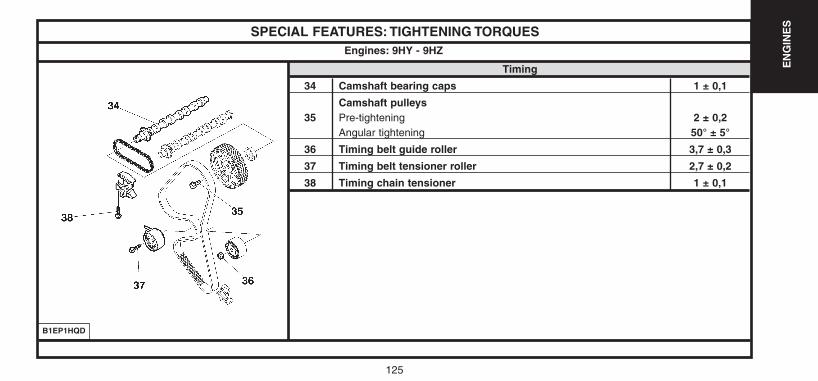
125
EN
GIN
ES
SPECIAL FEATURES: TIGHTENING TORQUES
Timing
34 Camshaft bearing caps 1 ± 0,1
Camshaft pulleys35 Pre-tightening 2 ± 0,2
Angular tightening 50° ± 5°
36 Timing belt guide roller 3,7 ± 0,3
37 Timing belt tensioner roller 2,7 ± 0,2
38 Timing chain tensioner 1 ± 0,1
Engines: 9HY - 9HZ
B1EP1HQD
UK-C4-page048-130-2004 15/11/04 9:23 Page 125
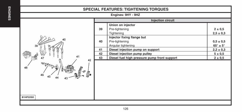
126
EN
GIN
ES
SPECIAL FEATURES: TIGHTENING TORQUES
Injection circuit
Union on injector39 Pre-tightening 2 ± 0,5
Tightening 2,5 ± 0,3Injector fixing flange but
40 Pre-tightening 0,5 ± 0,5Angular tightening 65° ± 5°
41 Diesel injection pump on support 2,2 ± 0,342 Diesel injection pump pulley 5 ± 0,543 Diesel fuel high pressure pump front support 2 ± 0,5
Engines: 9HY - 9HZ
B1HP22SD
UK-C4-page048-130-2004 15/11/04 9:23 Page 126
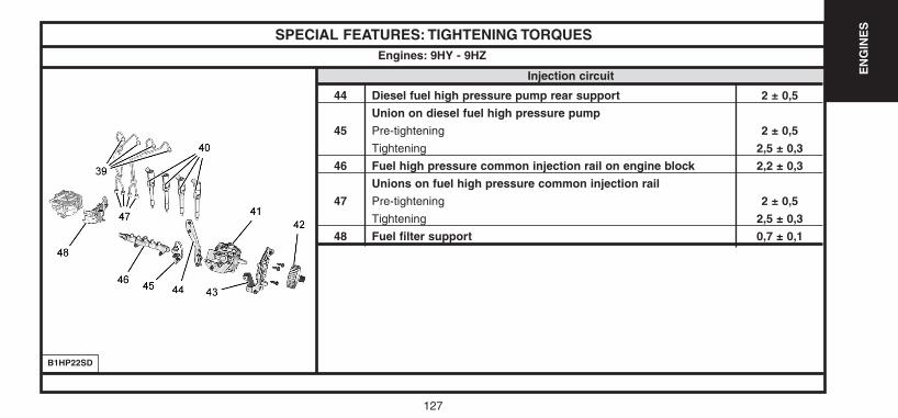
127
EN
GIN
ES
SPECIAL FEATURES: TIGHTENING TORQUES
Injection circuit
44 Diesel fuel high pressure pump rear support 2 ± 0,5
Union on diesel fuel high pressure pump
45 Pre-tightening 2 ± 0,5
Tightening 2,5 ± 0,3
46 Fuel high pressure common injection rail on engine block 2,2 ± 0,3
Unions on fuel high pressure common injection rail
47 Pre-tightening 2 ± 0,5
Tightening 2,5 ± 0,3
48 Fuel filter support 0,7 ± 0,1
Engines: 9HY - 9HZ
B1HP22SD
UK-C4-page048-130-2004 15/11/04 9:23 Page 127

128128
EN
GIN
ES
SPECIAL FEATURES: TIGHTENING TORQUES
Accessories
49 Multifunction support 2 ± 0,4
50 Alternator fixing screw 4,9 ± 1,2
51 Alternator power circuit fixing nuts 1,4 ± 0,2
52 Accessories tensioner roller 2,1 ± 0,2
Engines: 9HY - 9HZ
D1AP02NC
Version without particle filter
UK-C4-page048-130-2004 15/11/04 9:23 Page 128
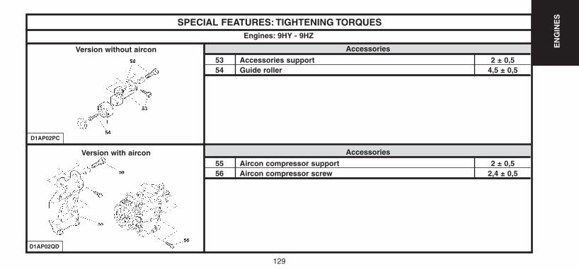
EN
GIN
ES
129
SPECIAL FEATURES: TIGHTENING TORQUES
Accessories
53 Accessories support 2 ± 0,554 Guide roller 4,5 ± 0,5
Engines: 9HY - 9HZ
D1AP02PC
Version without aircon
D1AP02QD
Accessories
55 Aircon compressor support 2 ± 0,556 Aircon compressor screw 2,4 ± 0,5
Version with aircon
UK-C4-page048-130-2004 15/11/04 9:23 Page 129
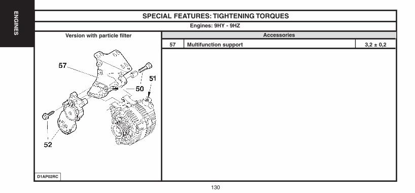
130
EN
GIN
ES
SPECIAL FEATURES: TIGHTENING TORQUES
Accessories
57 Multifunction support 3,2 ± 0,2
Engines: 9HY - 9HZ
D1AP02RC
Version with particle filter
UK-C4-page048-130-2004 15/11/04 9:23 Page 130
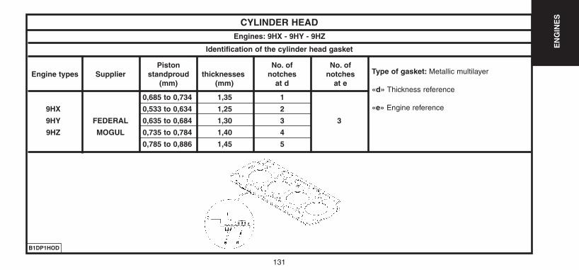
131
EN
GIN
ES
CYLINDER HEADEngines: 9HX - 9HY - 9HZ
Identification of the cylinder head gasket
B1DP1HOD
Piston No. of No. of Engine types Supplier standproud thicknesses notches notches
(mm) (mm) at d at e
0,685 to 0,734 1,35 1
9HX 0,533 to 0,634 1,25 2
9HY FEDERAL 0,635 to 0,684 1,30 3 3
9HZ MOGUL 0,735 to 0,784 1,40 4
0,785 to 0,886 1,45 5
Type of gasket: Metallic multilayer
«d» Thickness reference
«e» Engine reference
UK-C4-page131-237-2004 15/11/04 9:19 Page 131
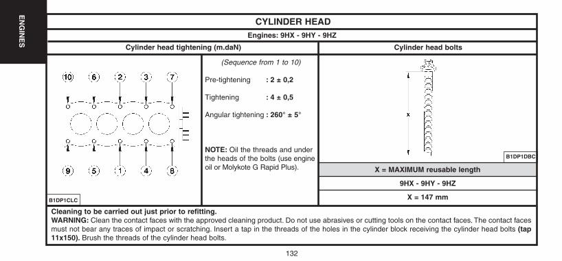
CYLINDER HEADEngines: 9HX - 9HY - 9HZ
Cylinder head tightening (m.daN) Cylinder head bolts
X = MAXIMUM reusable length
(Sequence from 1 to 10)
Pre-tightening : 2 ± 0,2
Tightening : 4 ± 0,5
Angular tightening : 260° ± 5°
NOTE: Oil the threads and underthe heads of the bolts (use engineoil or Molykote G Rapid Plus).
B1DP1DBC
B1DP1CLC
Cleaning to be carried out just prior to refitting.WARNING: Clean the contact faces with the approved cleaning product. Do not use abrasives or cutting tools on the contact faces. The contact facesmust not bear any traces of impact or scratching. Insert a tap in the threads of the holes in the cylinder block receiving the cylinder head bolts (tap11x150). Brush the threads of the cylinder head bolts.
9HX - 9HY - 9HZ
X = 147 mm
132
EN
GIN
ES
UK-C4-page131-237-2004 15/11/04 9:19 Page 132
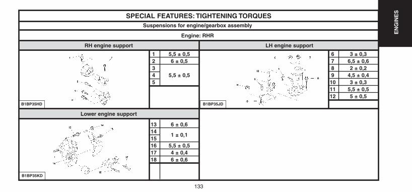
133
EN
GIN
ES
Lower engine support
SPECIAL FEATURES: TIGHTENING TORQUES
1 5,5 ± 0,52 6 ± 0,534 5,5 ± 0,55
13 6 ± 0,614
1 ± 0,11516 5,5 ± 0,517 4 ± 0,418 6 ± 0,6
B1BP35HD
Suspensions for engine/gearbox assembly
Engine: RHR
RH engine support LH engine support
B1BP35KD
B1BP35JD
6 3 ± 0,37 6,5 ± 0,68 2 ± 0,29 4,5 ± 0,410 3 ± 0,311 5,5 ± 0,512 5 ± 0,5
UK-C4-page131-237-2004 15/11/04 9:19 Page 133
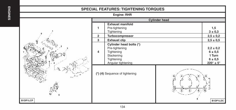
134
EN
GIN
ES
SPECIAL FEATURES: TIGHTENING TORQUES
Cylinder headExhaust manifold
1 Pre-tightening 1,5Tightening 3 ± 0,3
2 Turbocompressor 2,5 ± 0,23 Exhaust clip 2,5 ± 0,5
Cylinder head bolts (*)Pre-tightening 2,2 ± 0,2
4 Tightening 6 ± 0,5Slackening 1 TurnTightening 6 ± 0,5Angular tightening 220° ± 5°
Engine: RHR
B1DP1LCP B1DP1LDC
(*) (4) Sequence of tightening
UK-C4-page131-237-2004 15/11/04 9:19 Page 134
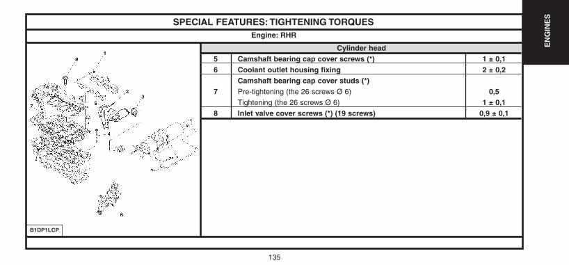
135
EN
GIN
ES
SPECIAL FEATURES: TIGHTENING TORQUES
Cylinder head5 Camshaft bearing cap cover screws (*) 1 ± 0,16 Coolant outlet housing fixing 2 ± 0,2
Camshaft bearing cap cover studs (*)7 Pre-tightening (the 26 screws Ø 6) 0,5
Tightening (the 26 screws Ø 6) 1 ± 0,18 Inlet valve cover screws (*) (19 screws) 0,9 ± 0,1
Engine: RHR
B1DP1LCP
UK-C4-page131-237-2004 15/11/04 9:19 Page 135
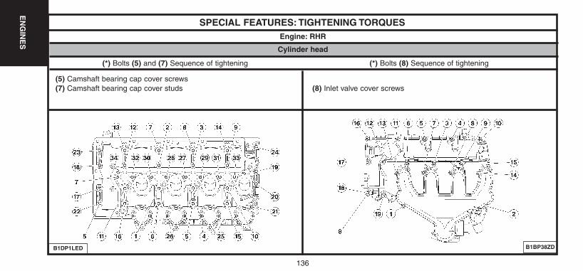
136
EN
GIN
ES
SPECIAL FEATURES: TIGHTENING TORQUESEngine: RHR
B1DP1LED
(*) Bolts (5) and (7) Sequence of tightening (*) Bolts (8) Sequence of tightening
Cylinder head
(5) Camshaft bearing cap cover screws(7) Camshaft bearing cap cover studs (8) Inlet valve cover screws
B1BP38ZD
UK-C4-page131-237-2004 15/11/04 9:19 Page 136
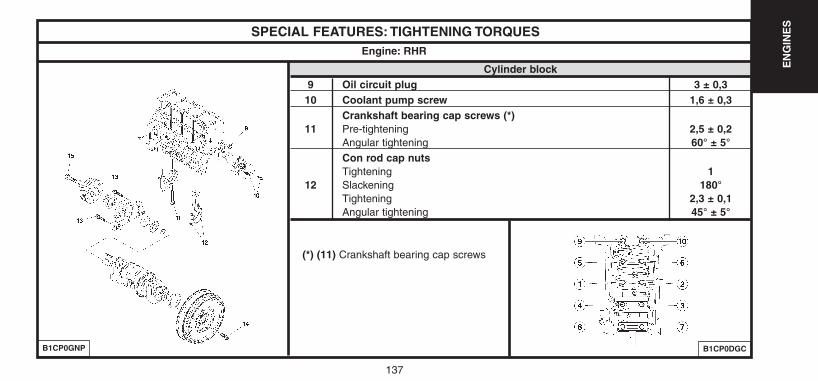
137
EN
GIN
ES
SPECIAL FEATURES: TIGHTENING TORQUES
Cylinder block9 Oil circuit plug 3 ± 0,310 Coolant pump screw 1,6 ± 0,3
Crankshaft bearing cap screws (*)11 Pre-tightening 2,5 ± 0,2
Angular tightening 60° ± 5°Con rod cap nutsTightening 1
12 Slackening 180°Tightening 2,3 ± 0,1Angular tightening 45° ± 5°
Engine: RHR
B1CP0GNP B1CP0DGC
(*) (11) Crankshaft bearing cap screws
UK-C4-page131-237-2004 15/11/04 9:19 Page 137
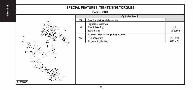
138
EN
GIN
ES
SPECIAL FEATURES: TIGHTENING TORQUES
Cylinder block
13 Front closing plate screw
Flywheel screws14 Pre-tightening 1,5
Tightening 4,7 ± 0,4
Accessories drive pulley screw15 Pre-tightening 7 ± 0,25
Angular tightening 60° ± 5°
Engine: RHR
B1CP0GNP
UK-C4-page131-237-2004 15/11/04 9:19 Page 138
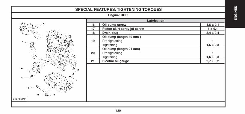
139
EN
GIN
ES
SPECIAL FEATURES: TIGHTENING TORQUES
Lubrication16 Oil pump screw 1,6 ± 0,117 Piston skirt spray jet screw 1 ± 0,118 Drain plug 3,4 ± 0,4
Oil sump (length 40 mm )19 Pre-tightening 1
Tightening 1,6 ± 0,3Oil sump (length 21 mm)
20 Pre-tightening 1Tightening 1,6 ± 0,3
21 Electric oil gauge 2,7 ± 0,2
Engine: RHR
B1CP0GPP
UK-C4-page131-237-2004 15/11/04 9:19 Page 139
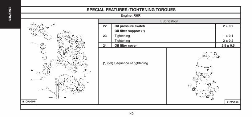
140
EN
GIN
ES
SPECIAL FEATURES: TIGHTENING TORQUES
Lubrication22 Oil pressure switch 2 ± 0,2
Oil filter support (*)23 Tightening 1 ± 0,1
Tightening 2 ± 0,224 Oil filter cover 2,5 ± 0,5
Engine: RHR
B1CP0GPP B1FP062C
(*) (23) Sequence of tightening
UK-C4-page131-237-2004 15/11/04 9:19 Page 140
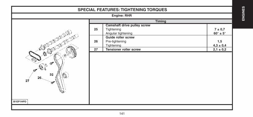
141
EN
GIN
ES
SPECIAL FEATURES: TIGHTENING TORQUES
TimingCamshaft drive pulley screw
25 Tightening 7 ± 0,7Angular tightening 60° ± 5°Guide roller screw
26 Pre-tightening 1,5Tightening 4,3 ± 0,4
27 Tensioner roller screw 2,1 ± 0,2
Engine: RHR
B1EP1HPD
UK-C4-page131-237-2004 15/11/04 9:19 Page 141
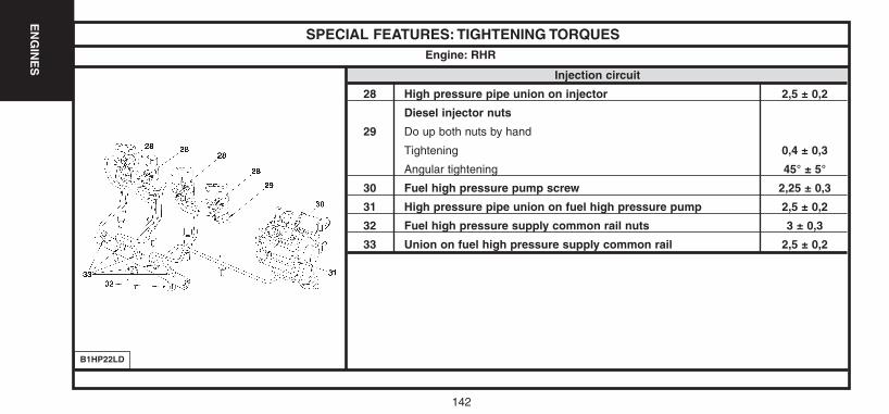
142
EN
GIN
ES
SPECIAL FEATURES: TIGHTENING TORQUES
Injection circuit
28 High pressure pipe union on injector 2,5 ± 0,2
Diesel injector nuts
29 Do up both nuts by hand
Tightening 0,4 ± 0,3
Angular tightening 45° ± 5°
30 Fuel high pressure pump screw 2,25 ± 0,3
31 High pressure pipe union on fuel high pressure pump 2,5 ± 0,2
32 Fuel high pressure supply common rail nuts 3 ± 0,3
33 Union on fuel high pressure supply common rail 2,5 ± 0,2
Engine: RHR
B1HP22LD
UK-C4-page131-237-2004 15/11/04 9:19 Page 142
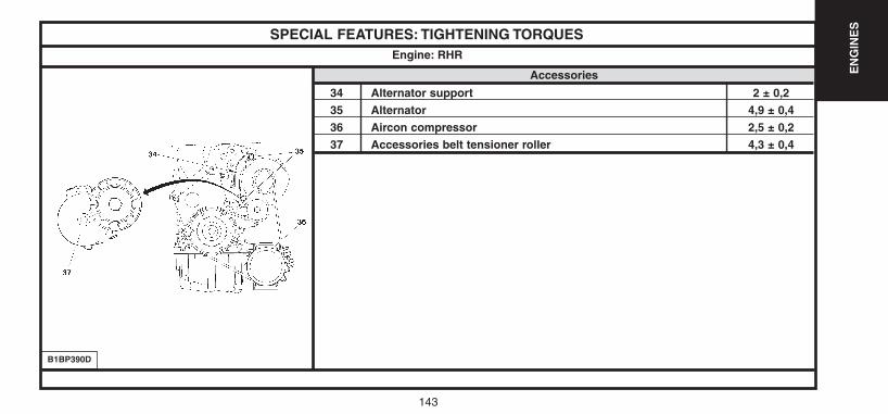
143
EN
GIN
ES
SPECIAL FEATURES: TIGHTENING TORQUES
Accessories
34 Alternator support 2 ± 0,2
35 Alternator 4,9 ± 0,4
36 Aircon compressor 2,5 ± 0,2
37 Accessories belt tensioner roller 4,3 ± 0,4
Engine: RHR
B1BP390D
UK-C4-page131-237-2004 15/11/04 9:19 Page 143
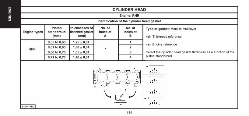
144
EN
GIN
ES
CYLINDER HEADEngine: RHR
Identification of the cylinder head gasket
B1DP1FPD
Piston thicknesses of No. of No. of Engine types standproud flattened gasket holes at holes at
(mm) (mm) A B
0,55 to 0,60 1,25 ± 0,04 1
RHR0,61 to 0,65 1,30 ± 0,04
12
0,66 to 0,70 1,35 ± 0,04 3
0,71 to 0,75 1,40 ± 0,04 4
Type of gasket: Metallic multilayer
«d» Thickness reference
«e» Engine reference
Select the cylinder head gasket thickness as a function of thepiston standproud.
UK-C4-page131-237-2004 15/11/04 9:19 Page 144
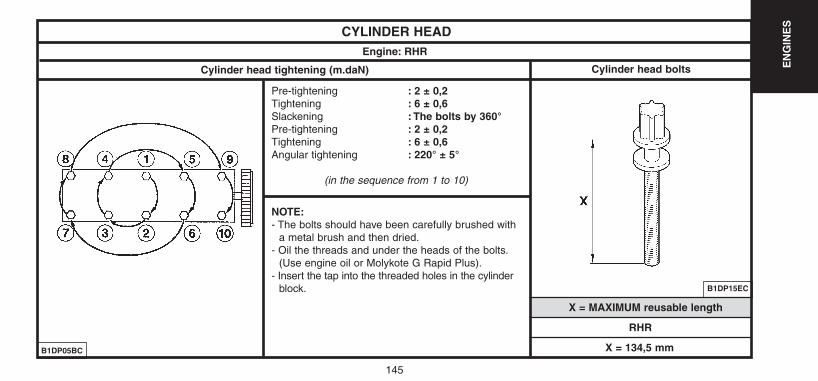
145
EN
GIN
ES
CYLINDER HEADEngine: RHR
Cylinder head tightening (m.daN) Cylinder head bolts
X = MAXIMUM reusable length
Pre-tightening : 2 ± 0,2Tightening : 6 ± 0,6Slackening : The bolts by 360°Pre-tightening : 2 ± 0,2Tightening : 6 ± 0,6Angular tightening : 220° ± 5°
(in the sequence from 1 to 10)
NOTE:- The bolts should have been carefully brushed with
a metal brush and then dried.- Oil the threads and under the heads of the bolts.
(Use engine oil or Molykote G Rapid Plus).- Insert the tap into the threaded holes in the cylinder
block. B1DP15EC
B1DP05BC
RHR
X = 134,5 mm
UK-C4-page131-237-2004 15/11/04 9:19 Page 145
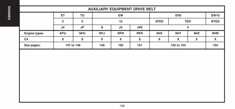
146
EN
GIN
ES
AUXILIARY EQUIPMENT DRIVE BELT
ET TU EW DV6 EW10
3 5 10 ATED TED BTED
J4 JP A J4 J4S 4
Engine types KFU NFU RFJ RFN RFK 9HX 9HY 9HZ RHR
C4 X X X X X X X X X
See pages: 147 to 148 149 150 151 152 to 153 154
UK-C4-page131-237-2004 15/11/04 9:19 Page 146
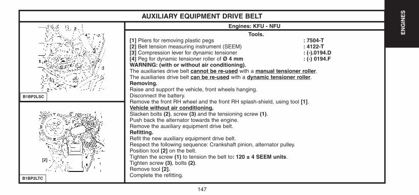
147
EN
GIN
ES
B1BP2LSC
B1BP2LTC
AUXILIARY EQUIPMENT DRIVE BELTEngines: KFU - NFU
Tools.[1] Pliers for removing plastic pegs : 7504-T[2] Belt tension measuring instrument (SEEM) : 4122-T [3] Compression lever for dynamic tensioner : (-).0194.D[4] Peg for dynamic tensioner roller of Ø 4 mm : (-) 0194.FWARNING: (with or without air conditioning).The auxiliaries drive belt cannot be re-used with a manual tensioner roller.The auxiliaries drive belt can be re-used with a dynamic tensioner roller.Removing.Raise and support the vehicle, front wheels hanging.Disconnect the battery.Remove the front RH wheel and the front RH splash-shield, using tool [1].Vehicle without air conditioning.Slacken bolts (2), screw (3) and the tensioning screw (1).Push back the alternator towards the engine.Remove the auxiliary equipment drive belt.Refitting.Refit the new auxiliary equipment drive belt.Respect the following sequence: Crankshaft pinion, alternator pulley.Position tool [2] on the belt.Tighten the screw (1) to tension the belt to: 120 ± 4 SEEM units.Tighten screw (3), bolts (2).Remove tool [2].Complete the refitting.
UK-C4-page131-237-2004 15/11/04 9:19 Page 147

148
EN
GIN
ES
B1EP1GQD
AUXILIARY EQUIPMENT DRIVE BELTEngine: KFU
Vehicle with air conditioning.
Removing.Place tool [4] at «a».Compress the dynamic tensioner roller.Place tool [3] at «b».Remove the auxiliary equipment drive belt.
IMPERATIVE: Check that the dynamic tensioner roller turns freely (without play and without tightspots).Refitting.NOTE: Visually check the condition of the auxiliary equipment drive belt prior to refitting.Place tool [4] at «a».Compress the dynamic tensioner roller.Remove tool [3].Refit the auxiliary equipment drive belt.
Respect the following sequence:- Crankshaft pinion, aircon compressor pulley, alternator pulley, dynamic tensioner roller.- Remove the tools.- Complete the refitting.
UK-C4-page131-237-2004 15/11/04 9:19 Page 148
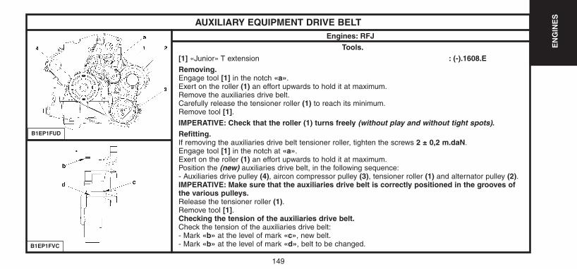
149
EN
GIN
ES
B1EP1FUD
B1EP1FVC
AUXILIARY EQUIPMENT DRIVE BELTEngines: RFJ
Tools.[1] «Junior» T extension : (-).1608.ERemoving.Engage tool [1] in the notch «a».Exert on the roller (1) an effort upwards to hold it at maximum.Remove the auxiliaries drive belt.Carefully release the tensioner roller (1) to reach its minimum.Remove tool [1].IMPERATIVE: Check that the roller (1) turns freely (without play and without tight spots).Refitting.If removing the auxiliaries drive belt tensioner roller, tighten the screws 2 ± 0,2 m.daN.Engage tool [1] in the notch at «a».Exert on the roller (1) an effort upwards to hold it at maximum.Position the (new) auxiliaries drive belt, in the following sequence:- Auxiliaries drive pulley (4), aircon compressor pulley (3), tensioner roller (1) and alternator pulley (2).IMPERATIVE: Make sure that the auxiliaries drive belt is correctly positioned in the grooves ofthe various pulleys.Release the tensioner roller (1).Remove tool [1].Checking the tension of the auxiliaries drive belt.Check the tension of the auxiliaries drive belt:- Mark «b» at the level of mark «c», new belt.- Mark «b» at the level of mark «d», belt to be changed.
UK-C4-page131-237-2004 15/11/04 9:19 Page 149
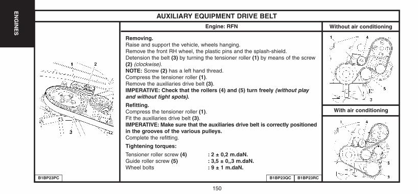
150
EN
GIN
ES
AUXILIARY EQUIPMENT DRIVE BELTEngine: RFN Without air conditioning
Removing.Raise and support the vehicle, wheels hanging.Remove the front RH wheel, the plastic pins and the splash-shield.Detension the belt (3) by turning the tensioner roller (1) by means of the screw(2) (clockwise).NOTE: Screw (2) has a left hand thread.Compress the tensioner roller (1).Remove the auxiliaries drive belt (3).IMPERATIVE: Check that the rollers (4) and (5) turn freely (without playand without tight spots).
Refitting.Compress the tensioner roller (1).Fit the auxiliaries drive belt (3).IMPERATIVE: Make sure that the auxiliaries drive belt is correctly positionedin the grooves of the various pulleys.Complete the refitting.
Tightening torques:
Tensioner roller screw (4) : 2 ± 0,2 m.daN.Guide roller screw (5) : 3,5 ± 0,,3 m.daN.Wheel bolts : 9 ± 1 m.daN.
B1BP23PC B1BP23QC B1BP23RC
With air conditioning
UK-C4-page131-237-2004 15/11/04 9:19 Page 150
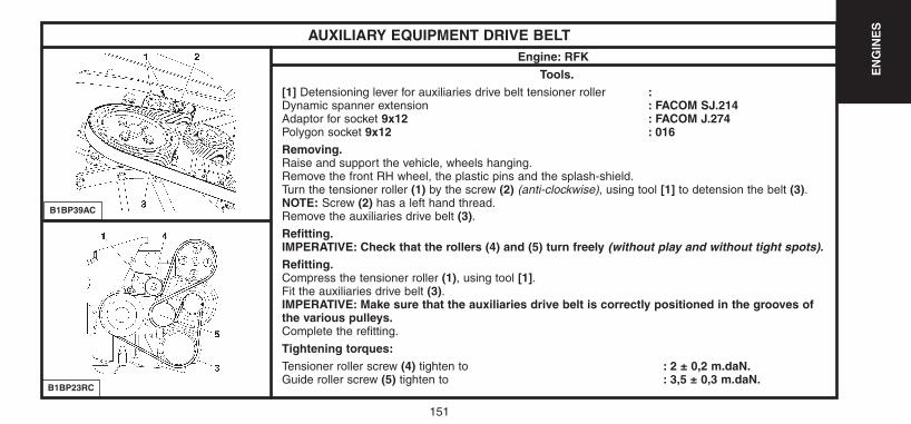
151
EN
GIN
ES
B1BP39AC
B1BP23RC
AUXILIARY EQUIPMENT DRIVE BELTEngine: RFK
Tools.[1] Detensioning lever for auxiliaries drive belt tensioner roller :Dynamic spanner extension : FACOM SJ.214Adaptor for socket 9x12 : FACOM J.274Polygon socket 9x12 : 016Removing.Raise and support the vehicle, wheels hanging.Remove the front RH wheel, the plastic pins and the splash-shield.Turn the tensioner roller (1) by the screw (2) (anti-clockwise), using tool [1] to detension the belt (3).NOTE: Screw (2) has a left hand thread.Remove the auxiliaries drive belt (3).Refitting.IMPERATIVE: Check that the rollers (4) and (5) turn freely (without play and without tight spots).Refitting.Compress the tensioner roller (1), using tool [1].Fit the auxiliaries drive belt (3).IMPERATIVE: Make sure that the auxiliaries drive belt is correctly positioned in the grooves ofthe various pulleys.Complete the refitting.
Tightening torques:Tensioner roller screw (4) tighten to : 2 ± 0,2 m.daN.Guide roller screw (5) tighten to : 3,5 ± 0,3 m.daN.
UK-C4-page131-237-2004 15/11/04 9:19 Page 151

152
EN
GIN
ES
B1EP18UD
B1BP3ACD
AUXILIARY EQUIPMENT DRIVE BELTEngines: 9HX - 9HY - 9HZ
Tools.[1] Dynamic tensioner roller lever (DV6 TED4 engine) : (-).0194-E3[1a] Dynamic tensioner roller lever (DV6 ATED4 engine) : (-).0194-E1[1b] Lever extension (DV6 ATED4 engine) : (-).0194-E2[2] Dynamic tensioner roller locking peg : (-).0194-F
IMPERATIVE: Respect the safety and cleanliness requirements specific to High pressureDiesel injection (HDi) engine versions.
Markings on the dynamic tensioner roller.«a» position «maximum wear» of the auxiliaries drive belt.«b» Nominal position.
Removing.
WARNING: Mark the direction of fitting of the auxiliaries drive belt in the case of re-use of the belt.
Compress the dynamic tensioner roller (1) by acting at «c» (clockwise), using tool [1].Peg using tool [2] at «d».Keep the dynamic tensioner roller (1) compressed and remove the auxiliaries drive belt.
UK-C4-page131-237-2004 15/11/04 9:19 Page 152
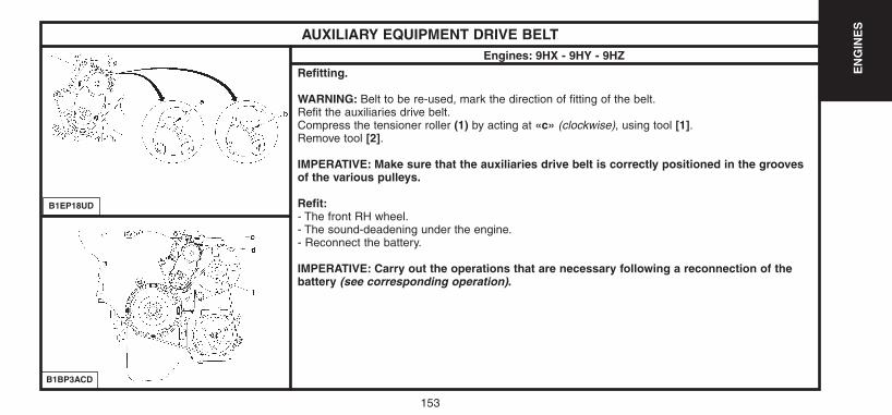
153
EN
GIN
ES
B1EP18UD
B1BP3ACD
AUXILIARY EQUIPMENT DRIVE BELTEngines: 9HX - 9HY - 9HZ
Refitting.
WARNING: Belt to be re-used, mark the direction of fitting of the belt.Refit the auxiliaries drive belt.Compress the tensioner roller (1) by acting at «c» (clockwise), using tool [1].Remove tool [2].
IMPERATIVE: Make sure that the auxiliaries drive belt is correctly positioned in the groovesof the various pulleys.
Refit:- The front RH wheel.- The sound-deadening under the engine.- Reconnect the battery.
IMPERATIVE: Carry out the operations that are necessary following a reconnection of thebattery (see corresponding operation).
UK-C4-page131-237-2004 15/11/04 9:19 Page 153
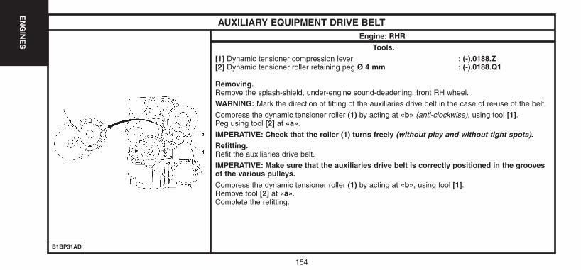
154
EN
GIN
ES
B1BP31AD
AUXILIARY EQUIPMENT DRIVE BELTEngine: RHR
Tools.[1] Dynamic tensioner compression lever : (-).0188.Z[2] Dynamic tensioner roller retaining peg Ø 4 mm : (-).0188.Q1
Removing.Remove the splash-shield, under-engine sound-deadening, front RH wheel.
WARNING: Mark the direction of fitting of the auxiliaries drive belt in the case of re-use of the belt.
Compress the dynamic tensioner roller (1) by acting at «b» (anti-clockwise), using tool [1].Peg using tool [2] at «a».
IMPERATIVE: Check that the roller (1) turns freely (without play and without tight spots).Refitting.Refit the auxiliaries drive belt.
IMPERATIVE: Make sure that the auxiliaries drive belt is correctly positioned in the groovesof the various pulleys.Compress the dynamic tensioner roller (1) by acting at «b», using tool [1].Remove tool [2] at «a».Complete the refitting.
UK-C4-page131-237-2004 15/11/04 9:19 Page 154
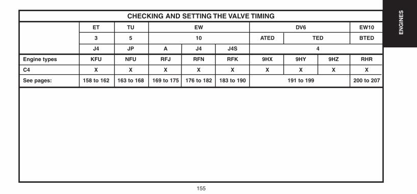
155
EN
GIN
ES
CHECKING AND SETTING THE VALVE TIMING
ET TU EW DV6 EW10
3 5 10 ATED TED BTED
J4 JP A J4 J4S 4
Engine types KFU NFU RFJ RFN RFK 9HX 9HY 9HZ RHR
C4 X X X X X X X X X
See pages: 158 to 162 163 to 168 169 to 175 176 to 182 183 to 190 191 to 199 200 to 207
UK-C4-page131-237-2004 15/11/04 9:19 Page 155
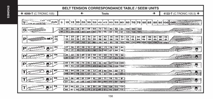
156
EN
GIN
ES
BELT TENSION CORRESPONDANCE TABLE / SEEM UNITS! 4099-T (C.TRONIC.105) @ Tools # 4122-T (C.TRONIC.105.5) !
UK-C4-page131-237-2004 15/11/04 9:19 Page 156
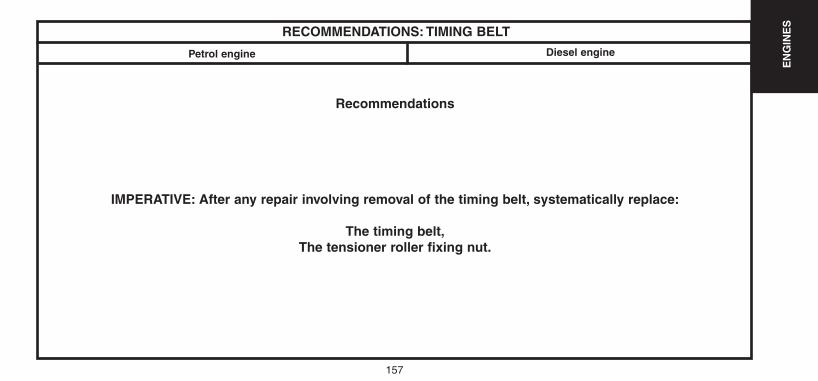
157
EN
GIN
ES
RECOMMENDATIONS: TIMING BELT
Petrol engine
Recommendations
IMPERATIVE: After any repair involving removal of the timing belt, systematically replace:
The timing belt,The tensioner roller fixing nut.
Diesel engine
UK-C4-page131-237-2004 15/11/04 9:19 Page 157
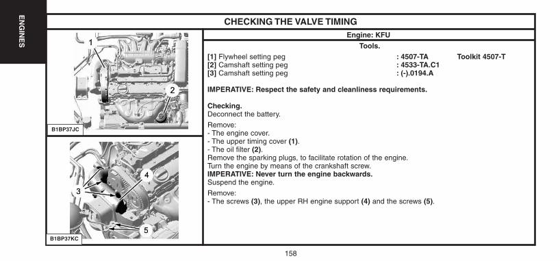
158
EN
GIN
ES
CHECKING THE VALVE TIMINGEngine: KFU
Tools.[1] Flywheel setting peg : 4507-TA Toolkit 4507-T[2] Camshaft setting peg : 4533-TA.C1[3] Camshaft setting peg : (-).0194.A
IMPERATIVE: Respect the safety and cleanliness requirements.
Checking.Deconnect the battery.
Remove:- The engine cover.- The upper timing cover (1).- The oil filter (2).Remove the sparking plugs, to facilitate rotation of the engine.Turn the engine by means of the crankshaft screw.IMPERATIVE: Never turn the engine backwards.Suspend the engine.
Remove:- The screws (3), the upper RH engine support (4) and the screws (5).
B1BP37JC
B1BP37KC
UK-C4-page131-237-2004 15/11/04 9:19 Page 158
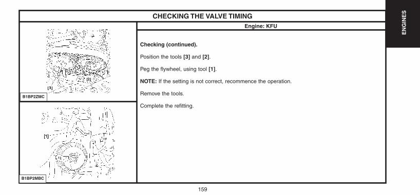
159
EN
GIN
ES
CHECKING THE VALVE TIMINGEngine: KFU
Checking (continued).
Position the tools [3] and [2].
Peg the flywheel, using tool [1].
NOTE: If the setting is not correct, recommence the operation.
Remove the tools.
Complete the refitting.
B1BP2ZMC
B1BP2MBC
UK-C4-page131-237-2004 15/11/04 9:19 Page 159
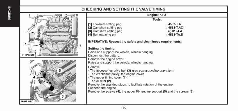
160
EN
GIN
ES
CHECKING AND SETTING THE VALVE TIMINGEngine: KFU
Tools.[1] Flywheel setting peg : 4507-T.A[2] Camshaft setting peg : 4533-T.AC1[3] Camshaft setting peg : (-).0194.A[4] Belt retaining pin : 4533-TA.D
IMPERATIVE: Respect the safety and cleanliness requirements.
Setting the timing.Raise and support the vehicle, wheels hanging.Disconnect the battery.Remove the engine cover.Raise and support the vehicle, wheels hanging.
Remove:- The accessories drive belt (3) (see corresponding operation).- The crankshaft pulley, the engine cover.- The upper timing cover (1).- The oil filter (2).Remove the sparking plugs, to facilitate rotation of the engine.Suspend the engine.Remove the screws (4), the upper RH engine support (5) and the screws (6).
B1BP37QD
B1BP37RC
UK-C4-page131-237-2004 15/11/04 9:19 Page 160
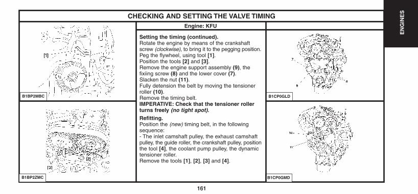
161
EN
GIN
ES
161
CHECKING AND SETTING THE VALVE TIMINGEngine: KFU
Setting the timing (continued).Rotate the engine by means of the crankshaftscrew (clockwise), to bring it to the pegging position.Peg the flywheel, using tool [1].Position the tools [2] and [3].Remove the engine support assembly (9), thefixiing screw (8) and the lower cover (7).Slacken the nut (11).Fully detension the belt by moving the tensionerroller (10).Remove the timing belt.IMPERATIVE: Check that the tensioner rollerturns freely (no tight spot).Refitting.Position the (new) timing belt, in the followingsequence:- The inlet camshaft pulley, the exhaust camshaftpulley, the guide roller, the crankshaft pulley, positionthe tool [4], the coolant pump pulley, the dynamictensioner roller.Remove the tools [1], [2], [3] and [4].
B1BP2MBC
B1BP2ZMC
B1CP0GLD
B1CP0GMD
UK-C4-page131-237-2004 15/11/04 9:19 Page 161
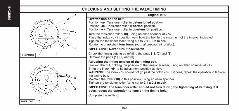
162
EN
GIN
ES
CHECKING AND SETTING THE VALVE TIMINGEngine: KFU
Overtension on the belt.Position «a»: Tensioner roller in detensioned position.Position «b»: Tensioner roller in normal position.Position «c»: Tensioner roller in overtension position.
Turn the tensioner roller (10), using an allen spanner at «e».Place the index «d» in position «c», hold the belt to the maximum of the interval indicated.Tighten the tensioner roller fixing nut to 2,1 ± 0,2 m.daN.Rotate the crankshaft four turns (normal direction of rotation).
IMPERATIVE: Never turn it backwards.Check the timing setting by refitting the pegs [1], [2] and [3].Remove the pegs [1], [2] and [3].Adjusting the fitting tension of the timing belt.Slacken the nut, holding the position of the tensioner roller, using an allen spanner at «e».Bring the index «d» to its adjustment position at «b».WARNING: The index «d» should not go past the notch «b». If it does, repeat the operation to tensionthe timing belt.Maintain the roller (10) in this position, using an allen spanner.Tighten the tensioner roller fixing nut to 2,1 ± 0,2 m.daN.
IMPERATIVE: The tensioner roller should not turn during the tightening of its fixing. If itdoes, repeat the operation to tension the timing belt.Complete the refitting.
B1EP1DTC
B1EP1DUC
UK-C4-page131-237-2004 15/11/04 9:19 Page 162
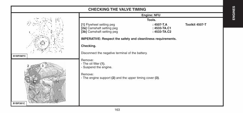
163
EN
GIN
ES
CHECKING THE VALVE TIMINGEngine: NFU
Tools.[1] Flywheel setting peg : 4507-T.A Toolkit 4507-T[2a] Camshaft setting peg : 4533-TA.C1[3b] Camshaft setting peg : 4533-TA.C2
IMPERATIVE: Respect the safety and cleanliness requirements.
Checking.
Disconnect the negative terminal of the battery.
Remove:- The oil filter (1).- Suspend the engine.
Remove:- The engine support (2) and the upper timing cover (3).
B1BP2M7C
B1BP381C
UK-C4-page131-237-2004 15/11/04 9:19 Page 163
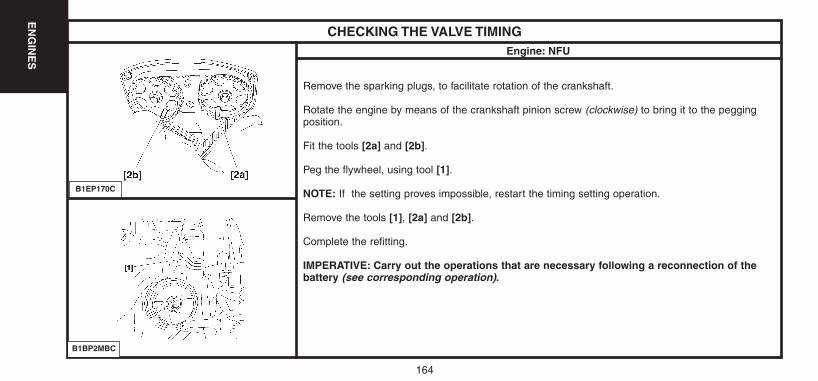
EN
GIN
ES
164
CHECKING THE VALVE TIMINGEngine: NFU
Remove the sparking plugs, to facilitate rotation of the crankshaft.
Rotate the engine by means of the crankshaft pinion screw (clockwise) to bring it to the peggingposition.
Fit the tools [2a] and [2b].
Peg the flywheel, using tool [1].
NOTE: If the setting proves impossible, restart the timing setting operation.
Remove the tools [1], [2a] and [2b].
Complete the refitting.
IMPERATIVE: Carry out the operations that are necessary following a reconnection of thebattery (see corresponding operation).
B1EP170C
B1BP2MBC
UK-C4-page131-237-2004 15/11/04 9:19 Page 164
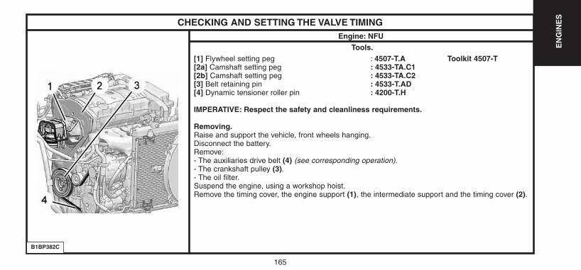
165
EN
GIN
ES
CHECKING AND SETTING THE VALVE TIMINGEngine: NFU
Tools.[1] Flywheel setting peg : 4507-T.A Toolkit 4507-T[2a] Camshaft setting peg : 4533-TA.C1[2b] Camshaft setting peg : 4533-TA.C2[3] Belt retaining pin : 4533-T.AD[4] Dynamic tensioner roller pin : 4200-T.H
IMPERATIVE: Respect the safety and cleanliness requirements.
Removing.Raise and support the vehicle, front wheels hanging.Disconnect the battery.Remove:- The auxiliaries drive belt (4) (see corresponding operation).- The crankshaft pulley (3).- The oil filter.Suspend the engine, using a workshop hoist.Remove the timing cover, the engine support (1), the intermediate support and the timing cover (2).
B1BP382C
UK-C4-page131-237-2004 15/11/04 9:19 Page 165

166
EN
GIN
ES
166
CHECKING AND SETTING THE VALVE TIMINGEngine: NFU
Peg the flywheel, using tool [1].
Position the tools [2a] and [2b].
Slacken the tensioner roller.Turn the dynamic tensioner roller so as to be ableto position the tool [4], with the aid of an Allen keyplaced at «a».
Turn the tensioner roller towards the right to bring itto the index «c» in position «b».
Peg the tensioner roller in this position in order toslacken the timing belt to the maximum.
IMPERATIVE: Never make the dynamic tensionerroller turn by a complete rotation.
Remove the timing belt (8).
Check that the rollers and the pump pulley turnfreely (no tight spot).
B1BP2MBC
B1EP170C
B1EP18PC
B1EP18QC
UK-C4-page131-237-2004 15/11/04 9:19 Page 166
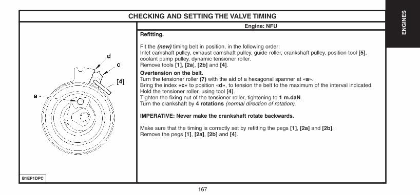
167
EN
GIN
ES
CHECKING AND SETTING THE VALVE TIMINGEngine: NFU
Refitting.
Fit the (new) timing belt in position, in the following order:Inlet camshaft pulley, exhaust camshaft pulley, guide roller, crankshaft pulley, position tool [5],coolant pump pulley, dynamic tensioner roller.Remove tools [1], [2a], [2b] and [4].Overtension on the belt.Turn the tensioner roller (7) with the aid of a hexagonal spanner at «a».Bring the index «c» to position «d», to tension the belt to the maximum of the interval indicated.Hold the tensioner roller, using tool [4].Tighten the fixing nut of the tensioner roller, tightening to 1 m.daN.Turn the crankshaft by 4 rotations (normal direction of rotation).
IMPERATIVE: Never make the crankshaft rotate backwards.
Make sure that the timing is correctly set by refitting the pegs [1], [2a] and [2b].Remove the pegs [1], [2a], [2b] and [4].
B1EP1DPC
UK-C4-page131-237-2004 15/11/04 9:19 Page 167
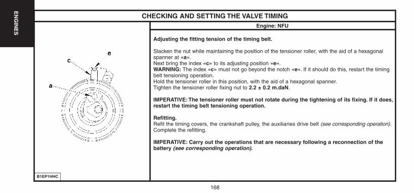
168
EN
GIN
ES
CHECKING AND SETTING THE VALVE TIMINGEngine: NFU
Adjusting the fitting tension of the timing belt.
Slacken the nut while maintaining the position of the tensioner roller, with the aid of a hexagonalspanner at «a».Next bring the index «c» to its adjusting position «e».WARNING: The index «c» must not go beyond the notch «e». If it should do this, restart the timingbelt tensioning operation.Hold the tensioner roller in this position, with the aid of a hexagonal spanner.Tighten the tensioner roller fixing nut to 2.2 ± 0.2 m.daN.
IMPERATIVE: The tensioner roller must not rotate during the tightening of its fixing. If it does,restart the timing belt tensioning operation.
Refitting.Refit the timing covers, the crankshaft pulley, the auxiliaries drive belt (see corresponding operation).Complete the refitting.
IMPERATIVE: Carry out the operations that are necessary following a reconnection of thebattery (see corresponding operation).
B1EP1HHC
UK-C4-page131-237-2004 15/11/04 9:19 Page 168
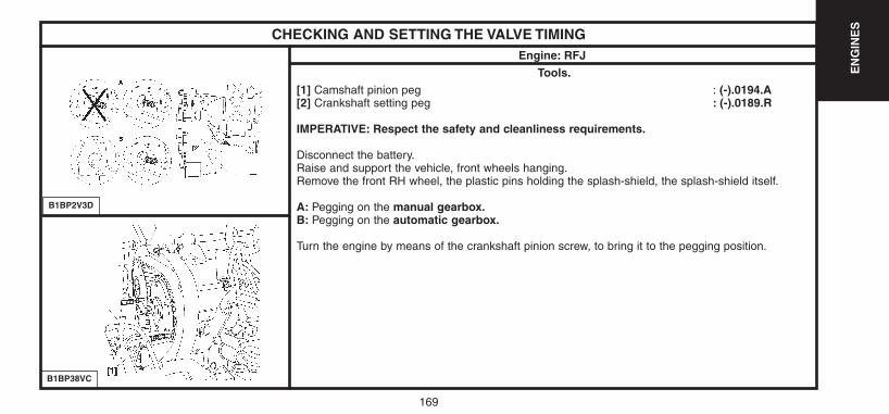
169
EN
GIN
ES
CHECKING AND SETTING THE VALVE TIMINGEngine: RFJ
Tools.[1] Camshaft pinion peg : (-).0194.A[2] Crankshaft setting peg : (-).0189.R
IMPERATIVE: Respect the safety and cleanliness requirements.
Disconnect the battery.Raise and support the vehicle, front wheels hanging.Remove the front RH wheel, the plastic pins holding the splash-shield, the splash-shield itself.
A: Pegging on the manual gearbox.B: Pegging on the automatic gearbox.
Turn the engine by means of the crankshaft pinion screw, to bring it to the pegging position.
B1BP2V3D
B1BP38VC
UK-C4-page131-237-2004 15/11/04 9:19 Page 169
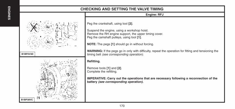
170
EN
GIN
ES
CHECKING AND SETTING THE VALVE TIMINGEngine: RFJ
Peg the crankshaft, using tool [2].
Suspend the engine, using a workshop hoist.Remove the RH engine support, the upper timing cover.Peg the camshaft pulleys, using tool [1].
NOTE: The pegs [1] should go in without forcing.
WARNING: If the pegs go in only with difficulty, repeat the operation for fitting and tensioning thetiming belt (see corresponding operation).
Refitting.
Remove tools [1] and [2].Complete the refitting.
IMPERATIVE: Carry out the operations that are necessary following a reconnection of thebattery (see corresponding operation).
B1BP2V3D
B1BP38VC
UK-C4-page131-237-2004 15/11/04 9:19 Page 170
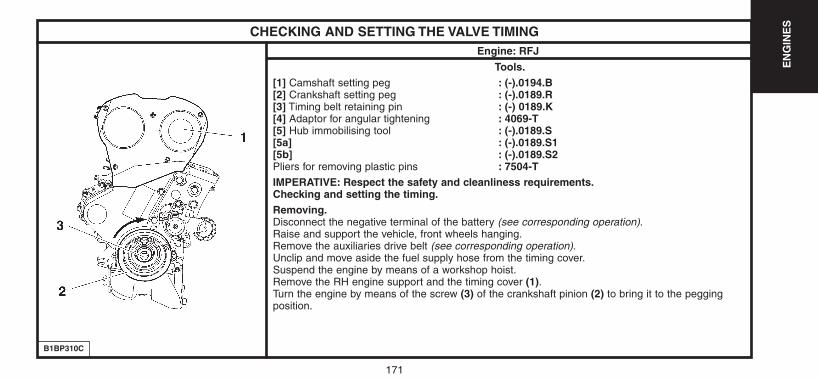
171
EN
GIN
ES
CHECKING AND SETTING THE VALVE TIMINGEngine: RFJ
Tools.[1] Camshaft setting peg : (-).0194.B[2] Crankshaft setting peg : (-).0189.R[3] Timing belt retaining pin : (-) 0189.K[4] Adaptor for angular tightening : 4069-T[5] Hub immobilising tool : (-).0189.S[5a] : (-).0189.S1[5b] : (-).0189.S2Pliers for removing plastic pins : 7504-TIMPERATIVE: Respect the safety and cleanliness requirements.Checking and setting the timing.Removing.Disconnect the negative terminal of the battery (see corresponding operation).Raise and support the vehicle, front wheels hanging.Remove the auxiliaries drive belt (see corresponding operation).Unclip and move aside the fuel supply hose from the timing cover.Suspend the engine by means of a workshop hoist.Remove the RH engine support and the timing cover (1).Turn the engine by means of the screw (3) of the crankshaft pinion (2) to bring it to the peggingposition.
B1BP310C
UK-C4-page131-237-2004 15/11/04 9:19 Page 171
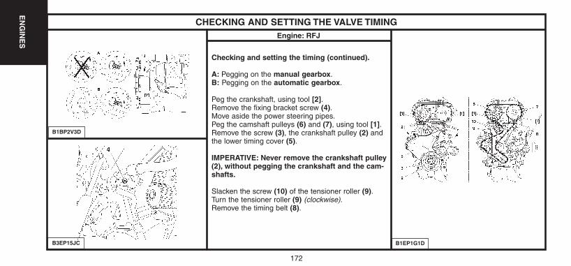
172
EN
GIN
ES
CHECKING AND SETTING THE VALVE TIMINGEngine: RFJ
Checking and setting the timing (continued).
A: Pegging on the manual gearbox.B: Pegging on the automatic gearbox.
Peg the crankshaft, using tool [2].Remove the fixing bracket screw (4).Move aside the power steering pipes.Peg the camshaft pulleys (6) and (7), using tool [1].Remove the screw (3), the crankshaft pulley (2) andthe lower timing cover (5).
IMPERATIVE: Never remove the crankshaft pulley(2), without pegging the crankshaft and the cam-shafts.
Slacken the screw (10) of the tensioner roller (9).Turn the tensioner roller (9) (clockwise).Remove the timing belt (8).
B1BP2V3D
B1EP1G1DB3EP15JC
UK-C4-page131-237-2004 15/11/04 9:19 Page 172
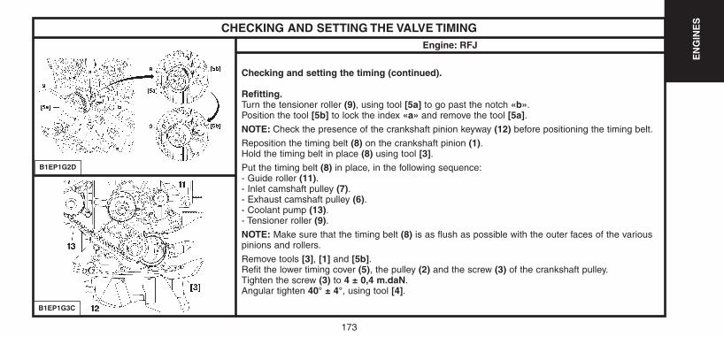
173
EN
GIN
ES
CHECKING AND SETTING THE VALVE TIMINGEngine: RFJ
Checking and setting the timing (continued).
Refitting.Turn the tensioner roller (9), using tool [5a] to go past the notch «b».Position the tool [5b] to lock the index «a» and remove the tool [5a].NOTE: Check the presence of the crankshaft pinion keyway (12) before positioning the timing belt.
Reposition the timing belt (8) on the crankshaft pinion (1).Hold the timing belt in place (8) using tool [3].Put the timing belt (8) in place, in the following sequence:- Guide roller (11).- Inlet camshaft pulley (7).- Exhaust camshaft pulley (6).- Coolant pump (13).- Tensioner roller (9).NOTE: Make sure that the timing belt (8) is as flush as possible with the outer faces of the variouspinions and rollers.
Remove tools [3], [1] and [5b].Refit the lower timing cover (5), the pulley (2) and the screw (3) of the crankshaft pulley.Tighten the screw (3) to 4 ± 0,4 m.daN.Angular tighten 40° ± 4°, using tool [4].
B1EP1G2D
B1EP1G3C
UK-C4-page131-237-2004 15/11/04 9:19 Page 173
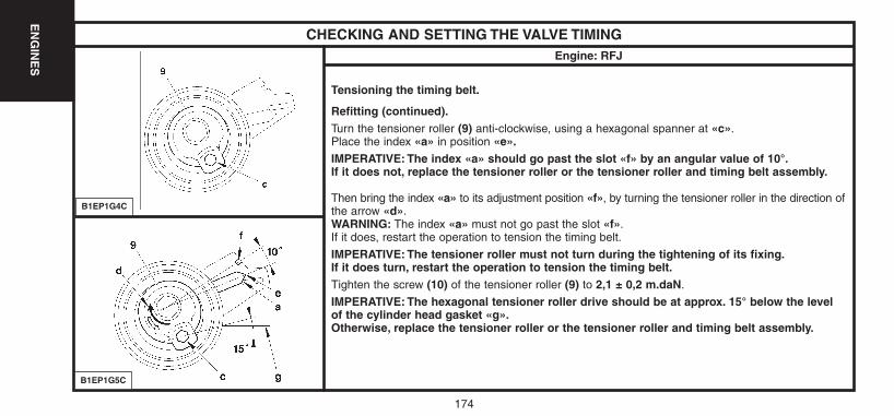
174
EN
GIN
ES
CHECKING AND SETTING THE VALVE TIMINGEngine: RFJ
Tensioning the timing belt.
Refitting (continued).Turn the tensioner roller (9) anti-clockwise, using a hexagonal spanner at «c».Place the index «a» in position «e».IMPERATIVE: The index «a» should go past the slot «f» by an angular value of 10°.If it does not, replace the tensioner roller or the tensioner roller and timing belt assembly.
Then bring the index «a» to its adjustment position «f», by turning the tensioner roller in the direction ofthe arrow «d».WARNING: The index «a» must not go past the slot «f».If it does, restart the operation to tension the timing belt.
IMPERATIVE: The tensioner roller must not turn during the tightening of its fixing.If it does turn, restart the operation to tension the timing belt.Tighten the screw (10) of the tensioner roller (9) to 2,1 ± 0,2 m.daN.
IMPERATIVE: The hexagonal tensioner roller drive should be at approx. 15° below the levelof the cylinder head gasket «g».Otherwise, replace the tensioner roller or the tensioner roller and timing belt assembly.
B1EP1G4C
B1EP1G5C
UK-C4-page131-237-2004 15/11/04 9:19 Page 174
175
EN
GIN
ES
CHECKING AND SETTING THE VALVE TIMINGEngine: RFJ
Tensioning the timing belt.
Refitting (continued).
Remove the tools [1] and [2].
Rotate the crankshaft ten times (normal direction of rotation).
IMPERATIVE: No exterior pressure or action should be applied on the timing belt.
Peg the inlet camshaft pulley, using tool [1].
Checking.
Timing belt tension
IMPERATIVE: Check the position of the index «a», it should be opposite the slot «f». If the position of the index «a» is not correct, repeatthe operations to tension the timig belt.
Complete the refitting.
IMPERATIVE: Carry out the operations that are necessary following a reconnection of the battery (see corresponding operation).
UK-C4-page131-237-2004 15/11/04 9:19 Page 175
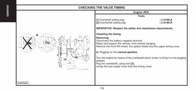
176
EN
GIN
ES
CHECKING THE VALVE TIMINGEngine: RFN
Tools.[1] Camshaft setting peg : (-).0189.A[2] Crankshaft setting peg : (-).0189.R
IMPERATIVE: Respect the safety and cleanliness requirements.
Checking the timing.Removing.Disconnect the battery negative terminal.Raise and support the vehicle, front wheels hanging.Remove the front RH wheel, the splash-shield and the upper timing cover.
A: Pegging on the manual gearbox.
Turn the engine by means of the crankshaft pinion screw, to bring it to the peggingposition.Peg the crankshaft, using tool [2].Unclip the fuel supply hose from the timing cover.
B1BP36QD
UK-C4-page131-237-2004 15/11/04 9:19 Page 176
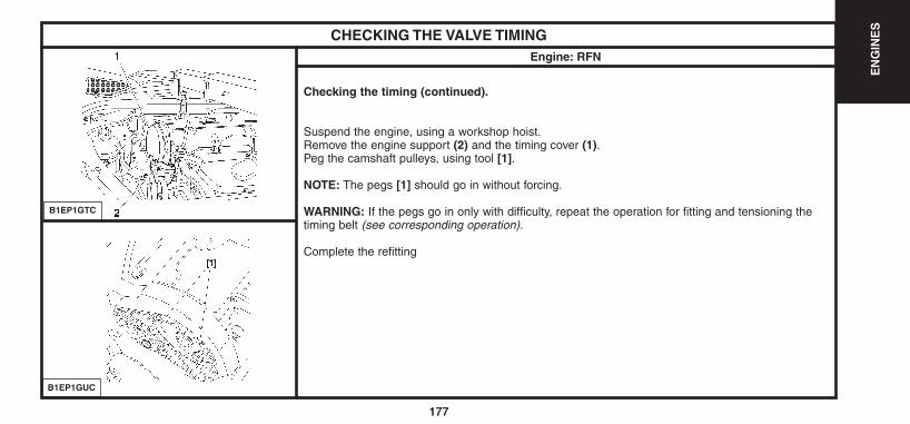
177
EN
GIN
ES
177
CHECKING THE VALVE TIMINGEngine: RFN
Checking the timing (continued).
Suspend the engine, using a workshop hoist.Remove the engine support (2) and the timing cover (1).Peg the camshaft pulleys, using tool [1].
NOTE: The pegs [1] should go in without forcing.
WARNING: If the pegs go in only with difficulty, repeat the operation for fitting and tensioning thetiming belt (see corresponding operation).
Complete the refitting
B1EP1GTC
B1EP1GUC
UK-C4-page131-237-2004 15/11/04 9:19 Page 177
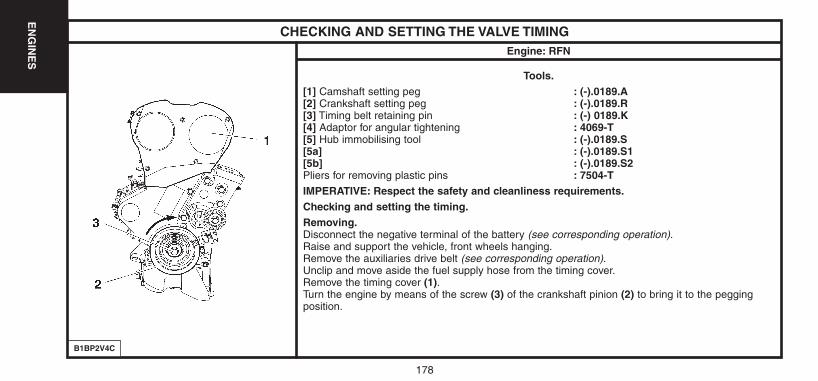
178
EN
GIN
ES
CHECKING AND SETTING THE VALVE TIMINGEngine: RFN
Tools.[1] Camshaft setting peg : (-).0189.A[2] Crankshaft setting peg : (-).0189.R[3] Timing belt retaining pin : (-) 0189.K[4] Adaptor for angular tightening : 4069-T[5] Hub immobilising tool : (-).0189.S[5a] : (-).0189.S1[5b] : (-).0189.S2Pliers for removing plastic pins : 7504-TIMPERATIVE: Respect the safety and cleanliness requirements.Checking and setting the timing.Removing.Disconnect the negative terminal of the battery (see corresponding operation).Raise and support the vehicle, front wheels hanging.Remove the auxiliaries drive belt (see corresponding operation).Unclip and move aside the fuel supply hose from the timing cover.Remove the timing cover (1).Turn the engine by means of the screw (3) of the crankshaft pinion (2) to bring it to the peggingposition.
B1BP2V4C
UK-C4-page131-237-2004 15/11/04 9:19 Page 178
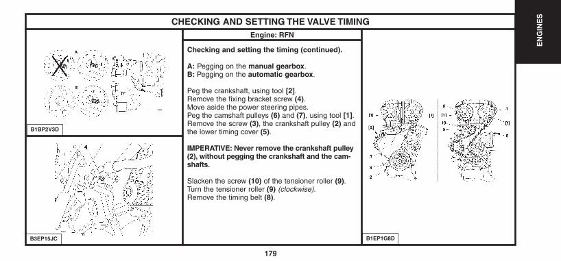
179
EN
GIN
ES
179
CHECKING AND SETTING THE VALVE TIMINGEngine: RFN
Checking and setting the timing (continued).
A: Pegging on the manual gearbox.B: Pegging on the automatic gearbox.
Peg the crankshaft, using tool [2].Remove the fixing bracket screw (4).Move aside the power steering pipes.Peg the camshaft pulleys (6) and (7), using tool [1].Remove the screw (3), the crankshaft pulley (2) andthe lower timing cover (5).
IMPERATIVE: Never remove the crankshaft pulley(2), without pegging the crankshaft and the cam-shafts.
Slacken the screw (10) of the tensioner roller (9).Turn the tensioner roller (9) (clockwise).Remove the timing belt (8).
B1BP2V3D
B3EP15JC B1EP1G8D
UK-C4-page131-237-2004 15/11/04 9:19 Page 179
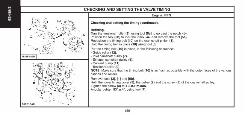
180
EN
GIN
ES
CHECKING AND SETTING THE VALVE TIMINGEngine: RFN
Checking and setting the timing (continued).
Refitting.Turn the tensioner roller (9), using tool [5a] to go past the notch «b».Position the tool [5b] to lock the index «a» and remove the tool [5a].Reposition the timing belt (10) on the crankshaft pinion (1).Hold the timing belt in place (10) using tool [3].Put the timing belt (10) in place, in the following sequence:- Guide roller (12).- Inlet camshaft pulley (7).- Exhaust camshaft pulley (6).- Coolant pump (11).- Tensioner roller (9).NOTE: Make sure that the timing belt (10) is as flush as possible with the outer faces of the variouspinions and rollers.
Remove tools [3], [1] and [5b].Refit the lower timing cover (5), the pulley (2) and the screw (3) of the crankshaft pulley.Tighten the screw (3) to 4 ± 0,4 m.daN.Angular tighten 53° ± 4°, using tool [4].
B1EP1G9D
B1EP1GAC
UK-C4-page131-237-2004 15/11/04 9:19 Page 180
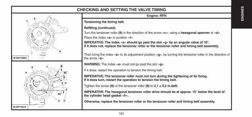
181
EN
GIN
ES
CHECKING AND SETTING THE VALVE TIMINGEngine: RFN
Tensioning the timing belt.
Refitting (continued).Turn the tensioner roller (9) in the direction of the arrow «c», using a hexagonal spanner at «d».
Place the index «a» in position «f»IMPERATIVE:The index «a» should go past the slot «g» by an angular value of 10°.If it does not, replace the tensioner roller or the tensioner roller and timing belt assembly.
Then bring the index «a» to its adjustment position «g», by turning the tensioner roller in the direction ofthe arrow «e».
WARNING: The index «a» must not go past the slot «g».
If it does, restart the operation to tension the timing belt.
IMPERATIVE:The tensioner roller must not turn during the tightening of its fixing.If it does turn, restart the operation to tension the timing belt.
Tighten the screw (8) of the tensioner roller (9) to 2,1 ± 0,2 m.daN.
IMPERATIVE:The hexagonal tensioner roller drive should be at approx. 15° below the level ofthe cylinder head gasket «h».
Otherwise, replace the tensioner roller or the tensioner roller and timing belt assembly.
B1EP1GBC
B1EP1GCC
UK-C4-page131-237-2004 15/11/04 9:19 Page 181

182
EN
GIN
ES
CHECKING AND SETTING THE VALVE TIMINGEngine: RFN
Tensioning the timing belt.
Refitting (continued).Remove the tools [1] and [2].Rotate the crankshaft ten times (normal direction of rotation).
IMPERATIVE: No exterior pressure or action should be applied on the timing belt.
Peg the inlet camshaft pulley, using tool [1].Checking.Timing belt tension.
IMPERATIVE: Check the position of the index «a», it should be opposite the slot «g». If the position of the index «a» is not correct, repeatthe operations to tension the timig belt.
Complete the refitting.
IMPERATIVE: Carry out the operations that are necessary following a reconnection of the battery (see corresponding operation).
UK-C4-page131-237-2004 15/11/04 9:19 Page 182
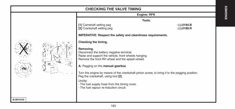
183
EN
GIN
ES
CHECKING THE VALVE TIMINGEngine: RFK
Tools.[1] Camshaft setting peg : (-).0194.B[2] Crankshaft setting peg : (-).0189.R
IMPERATIVE: Respect the safety and cleanliness requirements.
Checking the timing.
Removing.Disconnect the battery negative terminal.Raise and support the vehicle, front wheels hanging.Remove the front RH wheel and the splash-shield.
A: Pegging on the manual gearbox.
Turn the engine by means of the crankshaft pinion screw, to bring it to the pegging position.Peg the crankshaft, using tool [2].Unclip:- The fuel supply hose from the timing cover.- The fuel vapour re-induction circuit.
B1BP2V5D
UK-C4-page131-237-2004 15/11/04 9:19 Page 183

184
EN
GIN
ES
CHECKING THE VALVE TIMINGEngine: RFK
Checking the timing (continued).
Suspend the engine, using a workshop hoist.
Remove:- The RH engine support.- The upper timing cover.
Peg the camshaft pulleys, using tool [1].
NOTE: The pegs [1] should go in without forcing.
WARNING: If the pegs go in only with difficulty, repeat the operation for fitting and tensioning the timingbelt (see corresponding operation).
Remove the pegs [1] and [2].
Complete the refitting.
IMPERATIVE: Carry out the operations that are necessary following a reconnection of the battery(see corresponding operation).
B1EP1GRC
UK-C4-page131-237-2004 15/11/04 9:19 Page 184
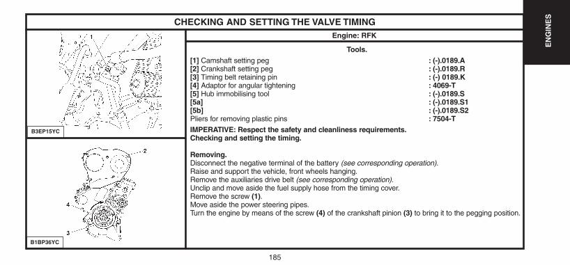
185
EN
GIN
ES
CHECKING AND SETTING THE VALVE TIMINGEngine: RFK
Tools.[1] Camshaft setting peg : (-).0189.A[2] Crankshaft setting peg : (-).0189.R[3] Timing belt retaining pin : (-) 0189.K[4] Adaptor for angular tightening : 4069-T[5] Hub immobilising tool : (-).0189.S[5a] : (-).0189.S1[5b] : (-).0189.S2Pliers for removing plastic pins : 7504-TIMPERATIVE: Respect the safety and cleanliness requirements.Checking and setting the timing.
Removing.Disconnect the negative terminal of the battery (see corresponding operation).Raise and support the vehicle, front wheels hanging.Remove the auxiliaries drive belt (see corresponding operation).Unclip and move aside the fuel supply hose from the timing cover.Remove the screw (1).Move aside the power steering pipes.Turn the engine by means of the screw (4) of the crankshaft pinion (3) to bring it to the pegging position.
B3EP15YC
B1BP36YC
UK-C4-page131-237-2004 15/11/04 9:19 Page 185

186
EN
GIN
ES
CHECKING AND SETTING THE VALVE TIMINGEngine: RFK
Checking and setting the timing (continued).
Peg the crankshaft using tool [2].
Suspend the engine, using a workshop hoist.
Remove:
- The upper RH engine support.
- The upper timing cover (2).
B1BP36YC
B1BP2V5D
UK-C4-page131-237-2004 15/11/04 9:19 Page 186
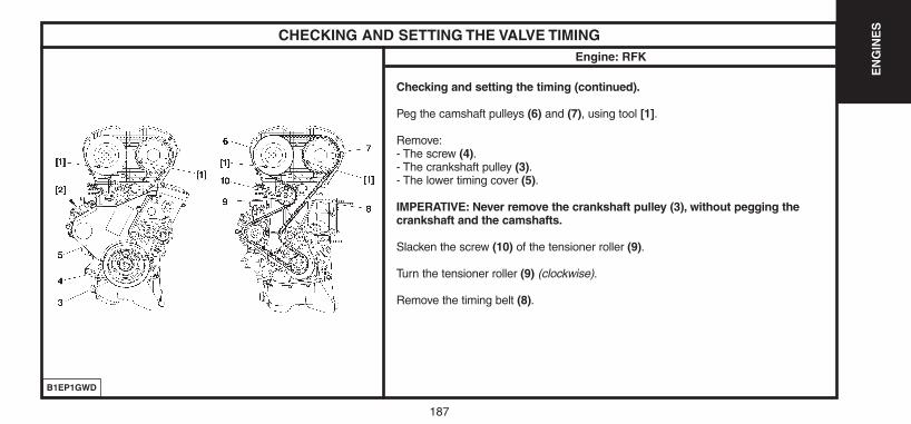
187
EN
GIN
ES
CHECKING AND SETTING THE VALVE TIMINGEngine: RFK
Checking and setting the timing (continued).
Peg the camshaft pulleys (6) and (7), using tool [1].
Remove:- The screw (4).- The crankshaft pulley (3).- The lower timing cover (5).
IMPERATIVE: Never remove the crankshaft pulley (3), without pegging thecrankshaft and the camshafts.
Slacken the screw (10) of the tensioner roller (9).
Turn the tensioner roller (9) (clockwise).
Remove the timing belt (8).
B1EP1GWD
UK-C4-page131-237-2004 15/11/04 9:19 Page 187

188
EN
GIN
ES
CHECKING AND SETTING THE VALVE TIMINGEngine: RFK
Checking and setting the timing (continued).
Refitting.Turn the tensioner roller (9), using tool [5a] to go past the notch «b».Position the tool [5b] to lock the index «a» and remove the tool [5a].Reposition the timing belt (8) on the crankshaft pinion (3).Hold the timing belt (8) in place, using tool [3].Put the timing belt (8) in place, in the following sequence:- Guide roller (12).- Inlet camshaft pulley (7).- Exhaust camshaft pulley (6).- Coolant pump (11).- Tensioner roller (9).NOTE: Make sure that the timing belt (8) is as flush as possible with the outer faces of the variouspinions and rollers.
Remove tools [3], [1] and [5b].Refit the lower timing cover (5), the pulley (3) and the screw (4) of the crankshaft pulley.Tighten the screw (4) to 4 ± 0,4 m.daN.Angular tighten 80° ± 5°, using tool [4].
B1EP1GXD
B1EP1GAC
UK-C4-page131-237-2004 15/11/04 9:19 Page 188
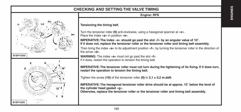
189
EN
GIN
ES
CHECKING AND SETTING THE VALVE TIMINGEngine: RFK
Tensioning the timing belt.
Turn the tensioner roller (9) anti-clockwise, using a hexagonal spanner at «c».Place the index «a» in position «e».
IMPERATIVE:The index «a» should go past the slot «f» by an angular value of 10°.If it does not, replace the tensioner roller or the tensioner roller and timing belt assembly.Then bring the index «a» to its adjustment position «f», by turning the tensioner roller in the direction ofthe arrow «d».
WARNING: The index «a» must not go past the slot «f».If it does, restart the operation to tension the timing belt.
IMPERATIVE:The tensioner roller must not turn during the tightening of its fixing. If it does turn,restart the operation to tension the timing belt.
Tighten the screw (10) of the tensioner roller (9) to 2,1 ± 0,2 m.daN.
IMPERATIVE:The hexagonal tensioner roller drive should be at approx. 15° below the level ofthe cylinder head gasket «g».Otherwise, replace the tensioner roller or the tensioner roller and timing belt assembly.
B1EP1GXD
B1EP1GZC
UK-C4-page131-237-2004 15/11/04 9:19 Page 189

190
EN
GIN
ES
CHECKING AND SETTING THE VALVE TIMINGEngine: RFK
Checking and setting the timing (continued).
Refitting (continued).Remove the tools [1] and [2].Refit the upper RH engine support.Remove the workshop hoist.Rotate the crankshaft ten times (normal direction of rotation).
IMPERATIVE: No exterior pressure or action should be applied on the timing belt.Suspend the engine using a workshop hoist.Remove the upper RH engine support.Peg the inlet camshaft pulley, using tool [1].Checking.Timing belt tension
IMPERATIVE: Check the position of the index «a», it should be opposite the slot «f». If the position of the index «a» is not correct, repeatthe operations to tension the timig belt.
Complete the refitting.
IMPERATIVE: Carry out the operations that are necessary following a reconnection of the battery (see corresponding operation).
UK-C4-page131-237-2004 15/11/04 9:19 Page 190
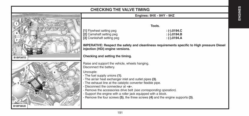
191
EN
GIN
ES
CHECKING THE VALVE TIMINGEngines: 9HX - 9HY - 9HZ
Tools.[1] Flywheel setting peg : (-).0194.C[2] Camshaft setting peg : (-).0194.B[3] Crankshaft setting peg : (-).0194.A
IMPERATIVE: Respect the safety and cleanliness requirements specific to High pressure Dieselinjection (HDi) engine versions.
Checking and setting the timing.
Raise and support the vehicle, wheels hanging.Disconnect the battery.
Uncouple:- The fuel supply unions (1).- The air/air heat exchanger inlet and outlet pipes (3).- The exhaust line at the catalytic converter flexible pipe.- Disconnect the connecteur at «a».- Remove the accessories drive belt (see corresponding operation).- Support the engine with a roller jack equipped with a block.- Remove the four screws (5), the three screws (4) and the engine supports (3).
B1BP38TD
B1BP38UD
UK-C4-page131-237-2004 15/11/04 9:19 Page 191
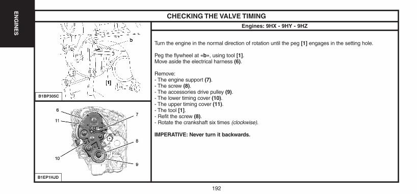
192
EN
GIN
ES
CHECKING THE VALVE TIMINGEngines: 9HX - 9HY - 9HZ
Turn the engine in the normal direction of rotation until the peg [1] engages in the setting hole.
Peg the flywheel at «b», using tool [1].Move aside the electrical harness (6).
Remove:- The engine support (7).- The screw (8).- The accessories drive pulley (9).- The lower timing cover (10).- The upper timing cover (11).- The tool [1].- Refit the screw (8).- Rotate the crankshaft six times (clockwise).
IMPERATIVE: Never turn it backwards.
B1BP305C
B1EP1HJD
UK-C4-page131-237-2004 15/11/04 9:19 Page 192
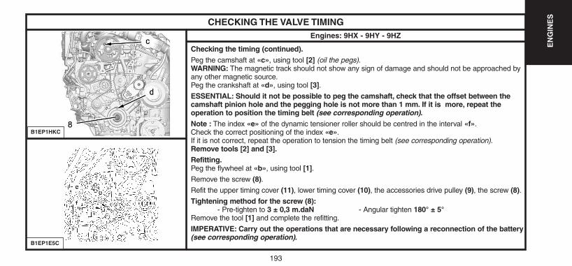
193
EN
GIN
ES
CHECKING THE VALVE TIMINGEngines: 9HX - 9HY - 9HZ
Checking the timing (continued).Peg the camshaft at «c», using tool [2] (oil the pegs).WARNING: The magnetic track should not show any sign of damage and should not be approached byany other magnetic source.Peg the crankshaft at «d», using tool [3].ESSENTIAL: Should it not be possible to peg the camshaft, check that the offset between thecamshaft pinion hole and the pegging hole is not more than 1 mm. If it is more, repeat the operation to position the timing belt (see corresponding operation).Note : The index «e» of the dynamic tensioner roller should be centred in the interval «f».Check the correct positioning of the index «e».If it is not correct, repeat the operation to tension the timing belt (see corresponding operation).Remove tools [2] and [3].Refitting.Peg the flywheel at «b», using tool [1].Remove the screw (8).Refit the upper timing cover (11), lower timing cover (10), the accessories drive pulley (9), the screw (8).Tightening method for the screw (8):
- Pre-tighten to 3 ± 0,3 m.daN - Angular tighten 180° ± 5°Remove the tool [1] and complete the refitting.
IMPERATIVE: Carry out the operations that are necessary following a reconnection of the battery(see corresponding operation).
B1EP1HKC
B1EP1E5C
UK-C4-page131-237-2004 15/11/04 9:19 Page 193
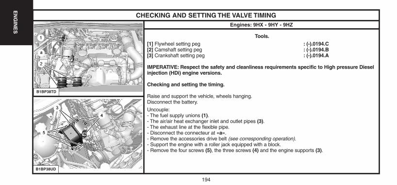
194
EN
GIN
ES
CHECKING AND SETTING THE VALVE TIMINGEngines: 9HX - 9HY - 9HZ
Tools.[1] Flywheel setting peg : (-).0194.C[2] Camshaft setting peg : (-).0194.B[3] Crankshaft setting peg : (-).0194.A
IMPERATIVE: Respect the safety and cleanliness requirements specific to High pressure Dieselinjection (HDi) engine versions.
Checking and setting the timing.
Raise and support the vehicle, wheels hanging.Disconnect the battery.
Uncouple:- The fuel supply unions (1).- The air/air heat exchanger inlet and outlet pipes (3).- The exhaust line at the flexible pipe.- Disconnect the connecteur at «a».- Remove the accessories drive belt (see corresponding operation).- Support the engine with a roller jack equipped with a block.- Remove the four screws (5), the three screws (4) and the engine supports (3).
B1BP38TD
B1BP38UD
UK-C4-page131-237-2004 15/11/04 9:19 Page 194
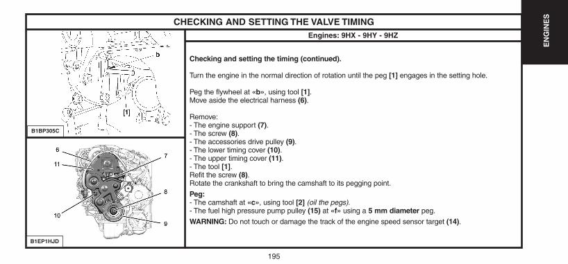
195
EN
GIN
ES
CHECKING AND SETTING THE VALVE TIMINGEngines: 9HX - 9HY - 9HZ
Checking and setting the timing (continued).
Turn the engine in the normal direction of rotation until the peg [1] engages in the setting hole.
Peg the flywheel at «b», using tool [1].Move aside the electrical harness (6).
Remove:- The engine support (7).- The screw (8).- The accessories drive pulley (9).- The lower timing cover (10).- The upper timing cover (11).- The tool [1].Refit the screw (8).Rotate the crankshaft to bring the camshaft to its pegging point.
Peg:- The camshaft at «c», using tool [2] (oil the pegs).- The fuel high pressure pump pulley (15) at «f» using a 5 mm diameter peg.
WARNING: Do not touch or damage the track of the engine speed sensor target (14).
B1BP305C
B1EP1HJD
UK-C4-page131-237-2004 15/11/04 9:19 Page 195
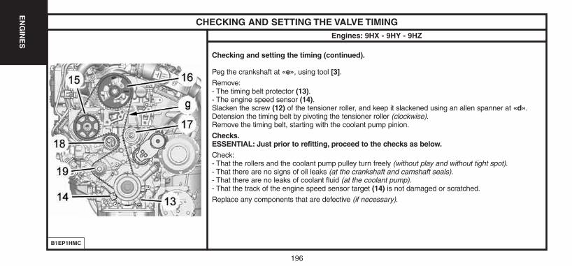
196
EN
GIN
ES
CHECKING AND SETTING THE VALVE TIMINGEngines: 9HX - 9HY - 9HZ
Checking and setting the timing (continued).
Peg the crankshaft at «e», using tool [3].Remove:- The timing belt protector (13).- The engine speed sensor (14).Slacken the screw (12) of the tensioner roller, and keep it slackened using an allen spanner at «d».Detension the timing belt by pivoting the tensioner roller (clockwise).Remove the timing belt, starting with the coolant pump pinion.
Checks.ESSENTIAL: Just prior to refitting, proceed to the checks as below.Check:- That the rollers and the coolant pump pulley turn freely (without play and without tight spot).- That there are no signs of oil leaks (at the crankshaft and camshaft seals).- That there are no leaks of coolant fluid (at the coolant pump).- That the track of the engine speed sensor target (14) is not damaged or scratched.
Replace any components that are defective (if necessary).
B1EP1HMC
UK-C4-page131-237-2004 15/11/04 9:19 Page 196
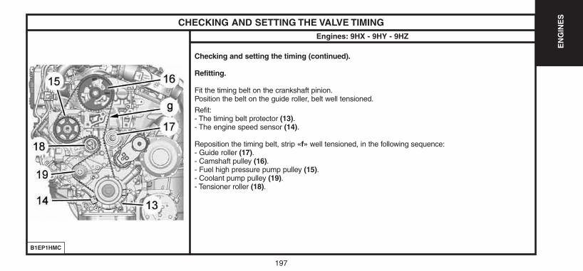
197
EN
GIN
ES
CHECKING AND SETTING THE VALVE TIMINGEngines: 9HX - 9HY - 9HZ
Checking and setting the timing (continued).
Refitting.
Fit the timing belt on the crankshaft pinion.Position the belt on the guide roller, belt well tensioned.
Refit:- The timing belt protector (13).- The engine speed sensor (14).
Reposition the timing belt, strip «f» well tensioned, in the following sequence:- Guide roller (17).- Camshaft pulley (16).- Fuel high pressure pump pulley (15).- Coolant pump pulley (19).- Tensioner roller (18).
B1EP1HMC
UK-C4-page131-237-2004 15/11/04 9:19 Page 197
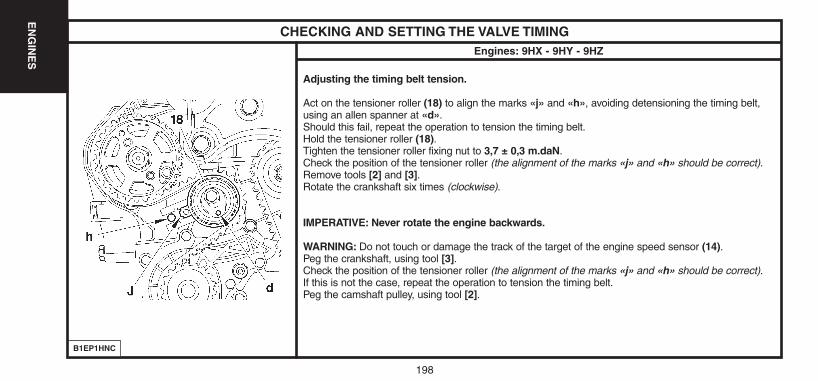
198
EN
GIN
ES
CHECKING AND SETTING THE VALVE TIMINGEngines: 9HX - 9HY - 9HZ
Adjusting the timing belt tension.
Act on the tensioner roller (18) to align the marks «j» and «h», avoiding detensioning the timing belt,using an allen spanner at «d».Should this fail, repeat the operation to tension the timing belt.Hold the tensioner roller (18).Tighten the tensioner roller fixing nut to 3,7 ± 0,3 m.daN.Check the position of the tensioner roller (the alignment of the marks «j» and «h» should be correct).Remove tools [2] and [3].Rotate the crankshaft six times (clockwise).
IMPERATIVE: Never rotate the engine backwards.
WARNING: Do not touch or damage the track of the target of the engine speed sensor (14).Peg the crankshaft, using tool [3].Check the position of the tensioner roller (the alignment of the marks «j» and «h» should be correct).If this is not the case, repeat the operation to tension the timing belt.Peg the camshaft pulley, using tool [2].
B1EP1HNC
UK-C4-page131-237-2004 15/11/04 9:19 Page 198
199
EN
GIN
ES
CHECKING AND SETTING THE VALVE TIMINGEngines: 9HX - 9HY - 9HZ
IMPERATIVE: Should it be impossible to peg the camshaft, check that the offset between the camshaft hole and the pegging hole is notmore than 1 mm. If the offset is too great, repeat the operation to position the timing belt (see corresponding operation).
Remove the tools [2] and [3].Refit tool [1] at «b».Remove the screw (8).Refit:- The upper timing cover (11).- The lower timing cover (12).- The pulley (9).- The screw (8).
Tightening method for the screw (8):- Pre-tighten to 3 ± 0,3 m.daN.- Angular tighten 180° ± 5°.- Remove tool [1].
Refit:- The engine support (7), tighten to 5,5 ± 0,9 m.daN.- The engine support (3).- The four screws (5), tighten to 5,5 ± 0,8 m.daN.- The three screws (4), tighten to 5,5 ± 0,8 m.daN.- The electrical harness (6).
Disengage the jack from under the engine.
Complete the refitting.
IMPERATIVE: Carry out the operations that are necessary followinga reconnection of the battery (see corresponding operation).
UK-C4-page131-237-2004 15/11/04 9:19 Page 199
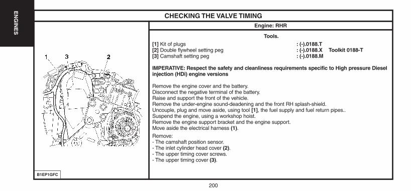
200
EN
GIN
ES
CHECKING THE VALVE TIMINGEngine: RHR
Tools.[1] Kit of plugs : (-).0188.T[2] Double flywheel setting peg : (-).0188.X Toolkit 0188-T[3] Camshaft setting peg : (-).0188.M
IMPERATIVE: Respect the safety and cleanliness requirements specific to High pressure Dieselinjection (HDi) engine versions
Remove the engine cover and the battery.Disconnect the negative terminal of the battery.Raise and support the front of the vehicle.Remove the under-engine sound-deadening and the front RH splash-shield.Uncouple, plug and move aside, using tool [1], the fuel supply and fuel return pipes..Suspend the engine, using a workshop hoist.Remove the engine support bracket and the engine support.Move aside the electrical harness (1).Remove:- The camshaft position sensor.- The inlet cylinder head cover (2).- The upper timing cover screws.- The upper timing cover (3).
B1EP1GFC
UK-C4-page131-237-2004 15/11/04 9:19 Page 200
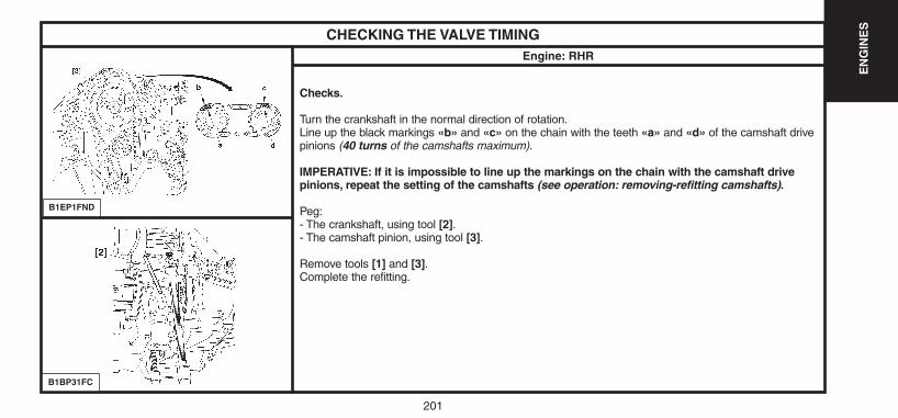
201
EN
GIN
ES
CHECKING THE VALVE TIMINGEngine: RHR
Checks.
Turn the crankshaft in the normal direction of rotation.Line up the black markings «b» and «c» on the chain with the teeth «a» and «d» of the camshaft drivepinions (40 turns of the camshafts maximum).
IMPERATIVE: If it is impossible to line up the markings on the chain with the camshaft drivepinions, repeat the setting of the camshafts (see operation: removing-refitting camshafts).
Peg:- The crankshaft, using tool [2].- The camshaft pinion, using tool [3].
Remove tools [1] and [3].Complete the refitting.
B1EP1FND
B1BP31FC
UK-C4-page131-237-2004 15/11/04 9:19 Page 201
202
EN
GIN
ES
CHECKING AND SETTING THE VALVE TIMINGEngine: RHR
Tools.[1] Kit of plugs : (-).0188.T[2] Double flywheel setting peg : (-).0188.X[3] Camshaft setting peg : (-).0188.M[4] Belt clamp : (-).0188.AD[5] Pinion centrer : (-).0188.AH[6] Flywheel lock : (-).0188.F[7] Pulley : (-).0188.P
IMPERATIVE: Respect the safety and cleanliness requirements specific to High pressure Diesel injection (HDi) engine versions.
Removing.Slacken the front RH wheel bolts.Raise and support the front RH side of the vehicle.Disconnect the negative terminal of the battery.
Remove:- The under-engine sound-deadening- The front RH wheel- The front RH splash-shield.- The engine cover.Remove the auxiliaries drive belt (see corresponding operation).
UK-C4-page131-237-2004 15/11/04 9:19 Page 202
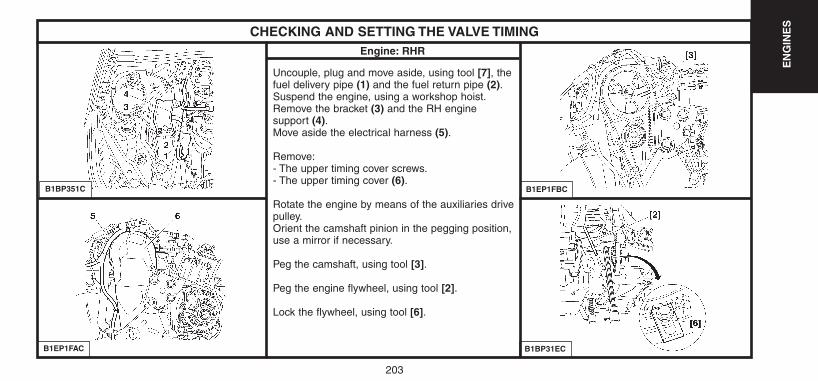
203
EN
GIN
ES
CHECKING AND SETTING THE VALVE TIMINGEngine: RHR
Uncouple, plug and move aside, using tool [7], thefuel delivery pipe (1) and the fuel return pipe (2).Suspend the engine, using a workshop hoist.Remove the bracket (3) and the RH engine support (4).Move aside the electrical harness (5).
Remove:- The upper timing cover screws.- The upper timing cover (6).
Rotate the engine by means of the auxiliaries drivepulley.Orient the camshaft pinion in the pegging position,use a mirror if necessary.
Peg the camshaft, using tool [3].
Peg the engine flywheel, using tool [2].
Lock the flywheel, using tool [6].
B1BP351C
B1EP1FAC
B1EP1FBC
B1BP31EC
UK-C4-page131-237-2004 15/11/04 9:19 Page 203
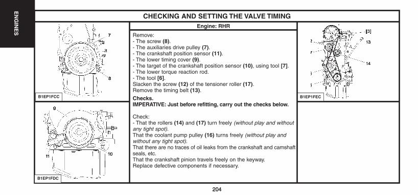
204
EN
GIN
ES
204
CHECKING AND SETTING THE VALVE TIMINGEngine: RHR
Remove:- The screw (8).- The auxiliaries drive pulley (7).- The crankshaft position sensor (11).- The lower timing cover (9).- The target of the crankshaft position sensor (10), using tool [7].- The lower torque reaction rod.- The tool [6].Slacken the screw (12) of the tensioner roller (17).Remove the timing belt (13).Checks.IMPERATIVE: Just before refitting, carry out the checks below.
Check:- That the rollers (14) and (17) turn freely (without play and withoutany tight spot).That the coolant pump pulley (16) turns freely (without play andwithout any tight spot).That there are no traces of oil leaks from the crankshaft and camshaftseals, etc.That the crankshaft pinion travels freely on the keyway.Replace defective components if necessary.
B1EP1FCC
B1EP1FDC
B1EP1FEC
UK-C4-page131-237-2004 15/11/04 9:19 Page 204
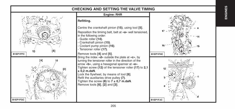
205
EN
GIN
ES
CHECKING AND SETTING THE VALVE TIMINGEngine: RHR
Refitting.
Centre the crankshaft pinion (15), using tool [5].Reposition the timimg belt, belt at «a» well tensioned,in the following order:- Guide roller (14).- Crankshaft pinion (15).- Coolant pump pinion (16).- Tensioner roller (17).Remove tools [4] and [5].Bring the index «d» outside the plate at «c», by turning the tensioner roller in the direction of thearrow «b», using a hexagonal spanner at «e».Tighten screw (12) of the tensioner roller (17) to 2,1± 0,2 m.daN.Lock the flywheel, by means of tool [6].Refit the auxiliaries drive pulley (7).Tighten the screw (8) to 7 ± 0,7 m.daN.Remove tools [6], [2] and [3].
B1EP1FFC
B1EP1FGC
B1EP1FHC
B1EP1FJC
UK-C4-page131-237-2004 15/11/04 9:19 Page 205
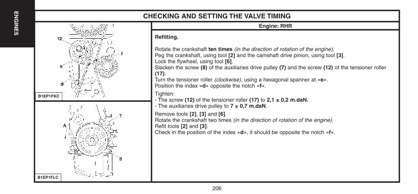
206
EN
GIN
ES
CHECKING AND SETTING THE VALVE TIMINGEngine: RHR
Refitting.
Rotate the crankshaft ten times (in the direction of rotation of the engine).Peg the crankshaft, using tool [2] and the camshaft drive pinion, using tool [3].Lock the flywheel, using tool [6].Slacken the screw (8) of the auxiliaries drive pulley (7) and the screw (12) of the tensioner roller(17).Turn the tensioner roller (clockwise), using a hexagonal spanner at «e».Position the index «d» opposite the notch «f».
Tighten:- The screw (12) of the tensioner roller (17) to 2,1 ± 0,2 m.daN.- The auxiliaries drive pulley to 7 ± 0,7 m.daN.
Remove tools [2], [3] and [6].Rotate the crankshaft two times (in the direction of rotation of the engine).Refit tools [2] and [3].Check in the position of the index «d», it should be opposite the notch «f».
B1EP1FKC
B1EP1FLC
UK-C4-page131-237-2004 15/11/04 9:19 Page 206
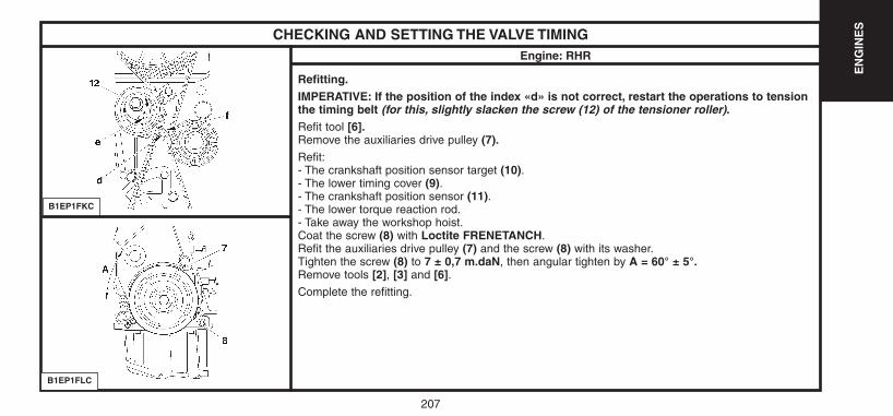
207
EN
GIN
ES
CHECKING AND SETTING THE VALVE TIMINGEngine: RHR
Refitting.IMPERATIVE: If the position of the index «d» is not correct, restart the operations to tensionthe timing belt (for this, slightly slacken the screw (12) of the tensioner roller).Refit tool [6].Remove the auxiliaries drive pulley (7).Refit:- The crankshaft position sensor target (10).- The lower timing cover (9).- The crankshaft position sensor (11).- The lower torque reaction rod.- Take away the workshop hoist.Coat the screw (8) with Loctite FRENETANCH.Refit the auxiliaries drive pulley (7) and the screw (8) with its washer.Tighten the screw (8) to 7 ± 0,7 m.daN, then angular tighten by A = 60° ± 5°.Remove tools [2], [3] and [6].Complete the refitting.
B1EP1FKC
B1EP1FLC
UK-C4-page131-237-2004 15/11/04 9:19 Page 207

208208
EN
GIN
ES
ADJUSTING THE CAMSHAFT POSITION SENSOREngines: 9HX - 9HY - 9HZ
NOTE: When removing a camshaft sensor, respect the airgap between the sensor and the target.
Slacken the screw (14).
Pusk back the camshaft position sensor (15) to the end of slots.
Do up the screw (14) a few turns.
Adjust the airgap (1,2 mm) of the camshaft position sensor (15).
New sensor.New camshaft position sensor:- Place the tip of the position sensor in contact with the target on the camshaft pulley (5).
Re-used sensor.Camshaft position sensor re-used:- Place a drill bit at «f» (Ø 9,5 mm) between the camshaft position sensor (15) and the timingcover (6).Tighten the screw (14) to 0,4 ± 0,1 m.daN.
B1EP1GLC
UK-C4-page131-237-2004 15/11/04 9:19 Page 208
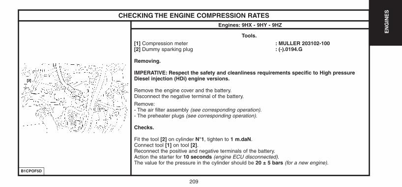
EN
GIN
ES
209
CHECKING THE ENGINE COMPRESSION RATESEngines: 9HX - 9HY - 9HZ
Tools.[1] Compression meter : MULLER 203102-100[2] Dummy sparking plug : (-).0194.G
Removing.
IMPERATIVE: Respect the safety and cleanliness requirements specific to High pressureDiesel injection (HDi) engine versions.
Remove the engine cover and the battery.Disconnect the negative terminal of the battery.
Remove:- The air filter assembly (see corresponding operation).- The preheater plugs (see corresponding operation).
Checks.
Fit the tool [2] on cylinder N°1, tighten to 1 m.daN.Connect tool [1] on tool [2].Reconnect the positive and negative terminals of the battery.Action the starter for 10 seconds (engine ECU disconnected).The value for the pressure in the cylinder should be 20 ± 5 bars (for a new engine).
B1CPOF5D
UK-C4-page131-237-2004 15/11/04 9:19 Page 209
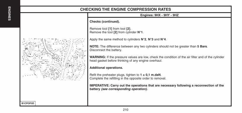
210
EN
GIN
ES
CHECKING THE ENGINE COMPRESSION RATESEngines: 9HX - 9HY - 9HZ
Checks (continued).
Remove tool [1] from tool [2].Remove the tool [2] from cylinder N°1.
Apply the same method to cylinders N°2, N°3 and N°4.
NOTE: The difference between any two cylinders should not be greater than 5 Bars.Disconnect the battery.
WARNING: If the pressure values are low, check the condition of the air filter and of the cylinderhead gasket before thinking of any engine overhaul.
Additional operations.
Refit the preheater plugs, tighten to 1 ± 0,1 m.daN.Complete the refitting in the opposite order to removal.
IMPERATIVE: Carry out the operations that are necessary following a reconnection of thebattery (see corresponding operation).
B1CPOF5D
UK-C4-page131-237-2004 15/11/04 9:19 Page 210
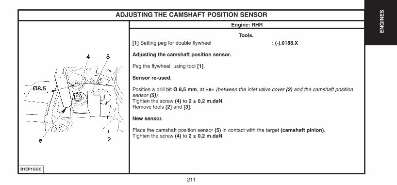
211
EN
GIN
ESADJUSTING THE CAMSHAFT POSITION SENSOR
Engine: RHR
Tools.[1] Setting peg for double flywheel : (-).0188.X
Adjusting the camshaft position sensor.
Peg the flywheel, using tool [1].
Sensor re-used.
Position a drill bit Ø 8,5 mm, at «e» (between the inlet valve cover (2) and the camshaft positionsensor (5)).Tighten the screw (4) to 2 ± 0,2 m.daN.Remove tools [2] and [3].
New sensor.
Place the camshaft position sensor (5) in contact with the target (camshaft pinion).Tighten the screw (4) to 2 ± 0,2 m.daN.
B1EP1GGC
UK-C4-page131-237-2004 15/11/04 9:19 Page 211
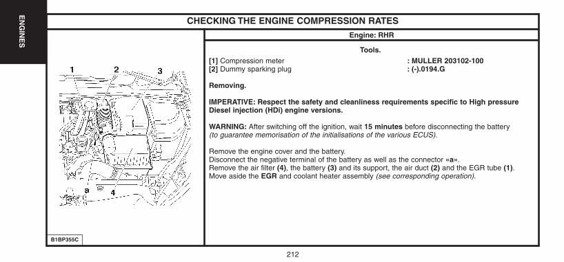
212
EN
GIN
ES
CHECKING THE ENGINE COMPRESSION RATES
Engine: RHR
Tools.[1] Compression meter : MULLER 203102-100[2] Dummy sparking plug : (-).0194.G
Removing.
IMPERATIVE: Respect the safety and cleanliness requirements specific to High pressureDiesel injection (HDi) engine versions.
WARNING: After switching off the ignition, wait 15 minutes before disconnecting the battery (to guarantee memorisation of the initialisations of the various ECUS).
Remove the engine cover and the battery.Disconnect the negative terminal of the battery as well as the connector «a».Remove the air filter (4), the battery (3) and its support, the air duct (2) and the EGR tube (1).Move aside the EGR and coolant heater assembly (see corresponding operation).
B1BP355C
UK-C4-page131-237-2004 15/11/04 9:19 Page 212
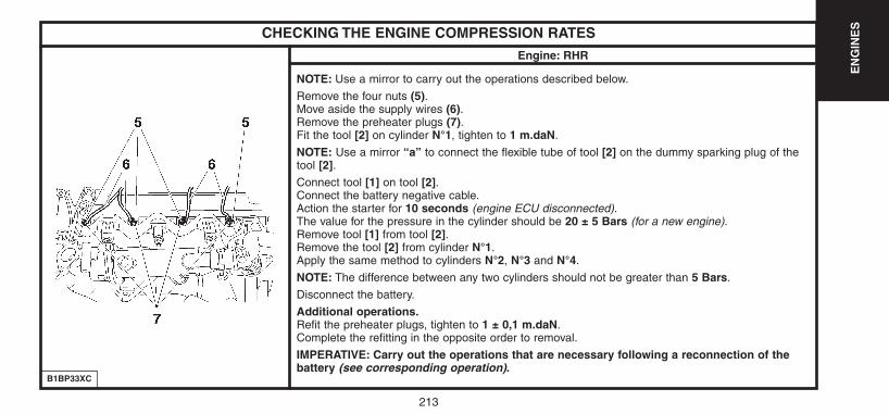
213
EN
GIN
ESCHECKING THE ENGINE COMPRESSION RATES
Engine: RHR
NOTE: Use a mirror to carry out the operations described below.
Remove the four nuts (5).Move aside the supply wires (6).Remove the preheater plugs (7).Fit the tool [2] on cylinder N°1, tighten to 1 m.daN.
NOTE: Use a mirror “a” to connect the flexible tube of tool [2] on the dummy sparking plug of thetool [2].Connect tool [1] on tool [2].Connect the battery negative cable.Action the starter for 10 seconds (engine ECU disconnected).The value for the pressure in the cylinder should be 20 ± 5 Bars (for a new engine).Remove tool [1] from tool [2].Remove the tool [2] from cylinder N°1.Apply the same method to cylinders N°2, N°3 and N°4.
NOTE: The difference between any two cylinders should not be greater than 5 Bars.
Disconnect the battery.
Additional operations.Refit the preheater plugs, tighten to 1 ± 0,1 m.daN.Complete the refitting in the opposite order to removal.
IMPERATIVE: Carry out the operations that are necessary following a reconnection of thebattery (see corresponding operation).
B1BP33XC
UK-C4-page131-237-2004 15/11/04 9:19 Page 213
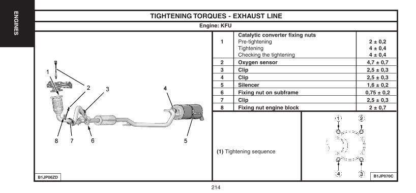
214
EN
GIN
ES
TIGHTENING TORQUES - EXHAUST LINE
Catalytic converter fixing nuts1 Pre-tightening 2 ± 0,2
Tightening 4 ± 0,4Checking the tightening 4 ± 0,4
2 Oxygen sensor 4,7 ± 0,73 Clip 2,5 ± 0,34 Clip 2,5 ± 0,35 Silencer 1,6 ± 0,26 Fixing nut on subframe 0,75 ± 0,27 Clip 2,5 ± 0,38 Fixing nut engine block 2 ± 0,7
Engine: KFU
B1JP06ZD B1JP070C
(1) Tightening sequence
UK-C4-page131-237-2004 15/11/04 9:19 Page 214
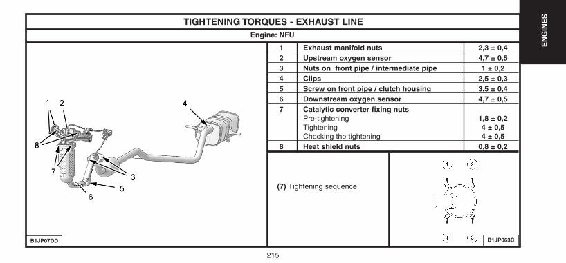
215
EN
GIN
ES
TIGHTENING TORQUES - EXHAUST LINE
1 Exhaust manifold nuts 2,3 ± 0,42 Upstream oxygen sensor 4,7 ± 0,53 Nuts on front pipe / intermediate pipe 1 ± 0,24 Clips 2,5 ± 0,35 Screw on front pipe / clutch housing 3,5 ± 0,46 Downstream oxygen sensor 4,7 ± 0,57 Catalytic converter fixing nuts
Pre-tightening 1,8 ± 0,2Tightening 4 ± 0,5Checking the tightening 4 ± 0,5
8 Heat shield nuts 0,8 ± 0,2
Engine: NFU
B1JP07DD B1JP063C
(7) Tightening sequence
UK-C4-page131-237-2004 15/11/04 9:19 Page 215
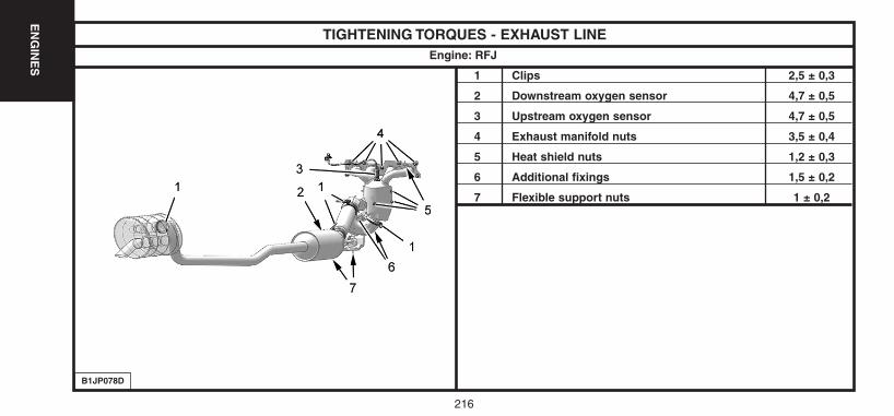
216
EN
GIN
ES
TIGHTENING TORQUES - EXHAUST LINE
1 Clips 2,5 ± 0,3
2 Downstream oxygen sensor 4,7 ± 0,5
3 Upstream oxygen sensor 4,7 ± 0,5
4 Exhaust manifold nuts 3,5 ± 0,4
5 Heat shield nuts 1,2 ± 0,3
6 Additional fixings 1,5 ± 0,2
7 Flexible support nuts 1 ± 0,2
Engine: RFJ
B1JP078D
UK-C4-page131-237-2004 15/11/04 9:19 Page 216
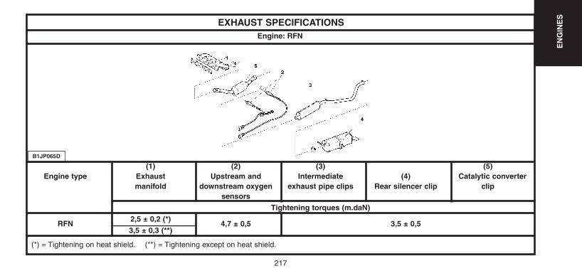
217
EN
GIN
ES
EXHAUST SPECIFICATIONS
(1) (2) (3) (5)Engine type Exhaust Upstream and Intermediate (4) Catalytic converter
manifold downstream oxygen exhaust pipe clips Rear silencer clip clip sensors
Tightening torques (m.daN)
RFN2,5 ± 0,2 (*)
4,7 ± 0,5 3,5 ± 0,53,5 ± 0,3 (**)
Engine: RFN
B1JP065D
(*) = Tightening on heat shield. (**) = Tightening except on heat shield.
UK-C4-page131-237-2004 15/11/04 9:19 Page 217
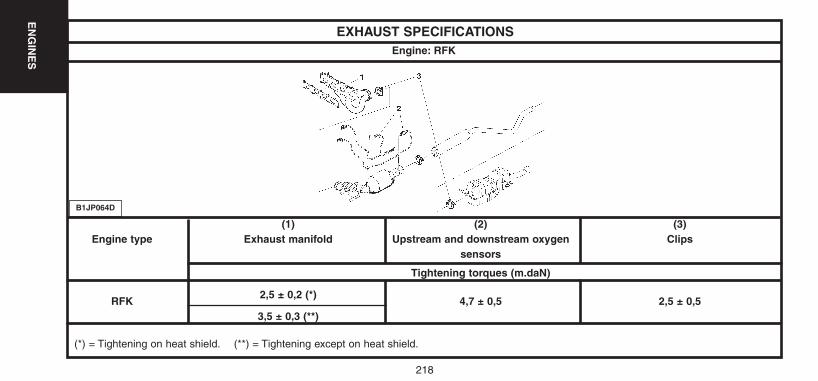
218
EN
GIN
ES
EXHAUST SPECIFICATIONS
(1) (2) (3)Engine type Exhaust manifold Upstream and downstream oxygen Clips
sensors
Tightening torques (m.daN)
RFK2,5 ± 0,2 (*)
4,7 ± 0,5 2,5 ± 0,53,5 ± 0,3 (**)
Engine: RFK
B1JP064D
(*) = Tightening on heat shield. (**) = Tightening except on heat shield.
UK-C4-page131-237-2004 15/11/04 9:19 Page 218
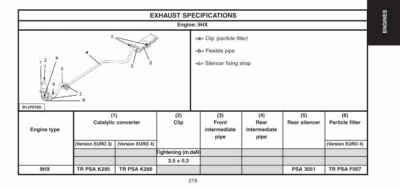
219
EN
GIN
ES
EXHAUST SPECIFICATIONS
(1) (2) (3) (4) (5) (6)Catalytic converter Clip Front Rear Rear silencer Particle filter
Engine type intermediate intermediatepipe pipe
(Version EURO 3) (Version EURO 4) (Version EURO 4)
Tightening (m.daN)
2,5 ± 0,3
9HX TR PSA K295 TR PSA K266 PSA 3051 TR PSA F007
Engine: 9HX
B1JP076D
«a» Clip (particle filter)
«b» Flexible pipe
«c» Silencer fixing strap
UK-C4-page131-237-2004 15/11/04 9:19 Page 219
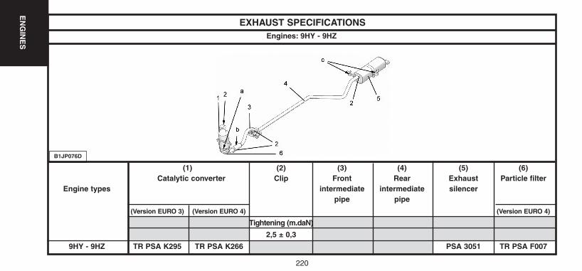
220
EN
GIN
ES
EXHAUST SPECIFICATIONS
(1) (2) (3) (4) (5) (6)Catalytic converter Clip Front Rear Exhaust Particle filter
Engine types intermediate intermediate silencerpipe pipe
(Version EURO 3) (Version EURO 4) (Version EURO 4)
Tightening (m.daN)
2,5 ± 0,3
9HY - 9HZ TR PSA K295 TR PSA K266 PSA 3051 TR PSA F007
Engines: 9HY - 9HZ
B1JP076D
UK-C4-page131-237-2004 15/11/04 9:19 Page 220
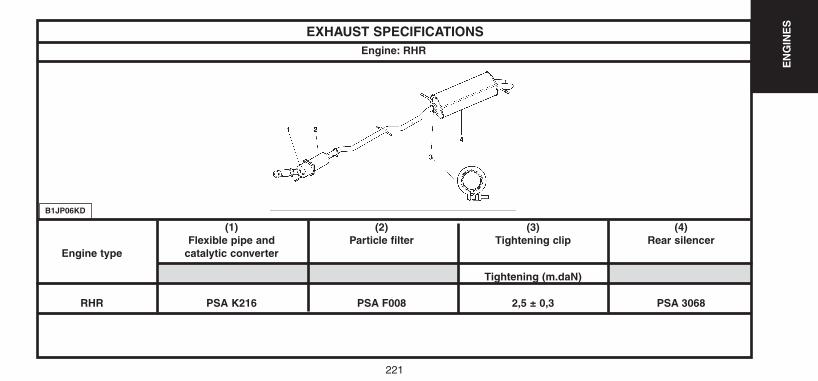
221
EN
GIN
ES
EXHAUST SPECIFICATIONS
(1) (2) (3) (4)Flexible pipe and Particle filter Tightening clip Rear silencer
Engine type catalytic converter
Tightening (m.daN)
RHR PSA K216 PSA F008 2,5 ± 0,3 PSA 3068
Engine: RHR
B1JP06KD
UK-C4-page131-237-2004 15/11/04 9:19 Page 221

222
EN
GIN
ES
EXHAUST SPECIFICATIONS
Engines: RFN - RFK - 9HX - 9HY - 9HZ - RHR
Repair.
Take all the precautions when working on a vehicle.
The flexible pipe must not come into contact with corrosive products. Do not deform the flexible pipemore than 20° angular (X), 20 mm axial, 25 mm shearing (Y) (flexible pipe not in place).
Do not deform the flexible pipe more than 3° angular (X), 0 mm axial, 3 mm shearing (Y) (flexiblepipe in place).
WARNING: Non respect of these precautions will shorten the life of the flexible pipe.
It is therefore imperative to disconnect or remove the exhaust line for any operations necessitatinglifting of the engine-gearbox.
B1JP02JC
UK-C4-page131-237-2004 15/11/04 9:19 Page 222
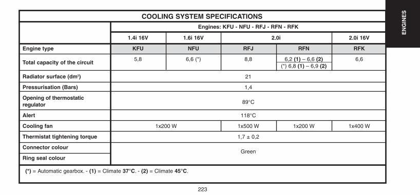
223
EN
GIN
ES
COOLING SYSTEM SPECIFICATIONSEngines: KFU - NFU - RFJ - RFN - RFK
Engine type
Total capacity of the circuit
Radiator surface (dm2)
Pressurisation (Bars)
Opening of thermostaticregulator
Alert
Cooling fan
Thermistat tightening torque
Connector colour
Ring seal colour
1.4i 16V 1.6i 16V 2.0i 2.0i 16V
KFU NFU RFJ RFN RFK
5,8 6,6 (*) 8,8 6,2 (1) – 6,6 (2) 6,6(*) 6,8 (1) – 6,9 (2)
21
1,4
89°C
118°C
1x200 W 1x500 W 1x200 W 1x400 W
1,7 ± 0,2
Green
(*) = Automatic gearbox. - (1) = Climate 37°C. - (2) = Climate 45°C.
UK-C4-page131-237-2004 15/11/04 9:19 Page 223
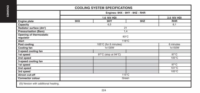
224
EN
GIN
ES
COOLING SYSTEM SPECIFICATIONSEngines: 9HX - 9HY - 9HZ - RHR
Engine plate CapacityRadiator surface (dm2)Pressurisation (Bars)Opening of thermostatic regulatorAlertPost coolingCooling fan2-speed cooling fan1st speed2nd speed3-speed cooling fan1st speed2nd speed3rd speedAircon cut-offConnector colour
1.6 16V HDi 2.0 16V HDi9HX 9HY 9HZ RHR
6,5 8,1211,4
83°C
118°C105°C (for 6 minutes) 6 minutes
1x130W 1x150W
97°C (stop at 94°C) 97°C105°C
97°C101°C105°C
115°CGreen
(1) Version with additional heating.
UK-C4-page131-237-2004 15/11/04 9:19 Page 224
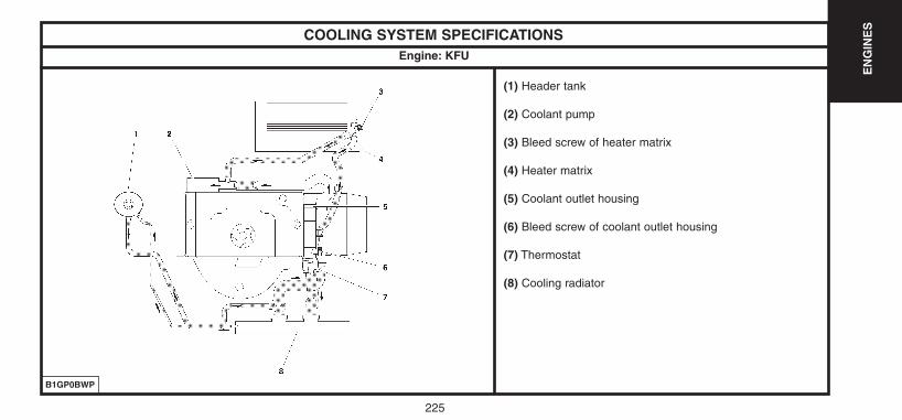
225
EN
GIN
ES
COOLING SYSTEM SPECIFICATIONS
B1GP0BWP
(1) Header tank
(2) Coolant pump
(3) Bleed screw of heater matrix
(4) Heater matrix
(5) Coolant outlet housing
(6) Bleed screw of coolant outlet housing
(7) Thermostat
(8) Cooling radiator
Engine: KFU
UK-C4-page131-237-2004 15/11/04 9:19 Page 225
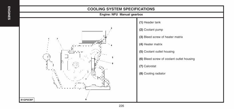
226
EN
GIN
ES
COOLING SYSTEM SPECIFICATIONS
B1GP0CBP
(1) Header tank
(2) Coolant pump
(3) Bleed screw of heater matrix
(4) Heater matrix
(5) Coolant outlet housing
(6) Bleed screw of coolant outlet housing
(7) Calorstat
(8) Cooling radiator
Engine: NFU Manual gearbox
UK-C4-page131-237-2004 15/11/04 9:19 Page 226
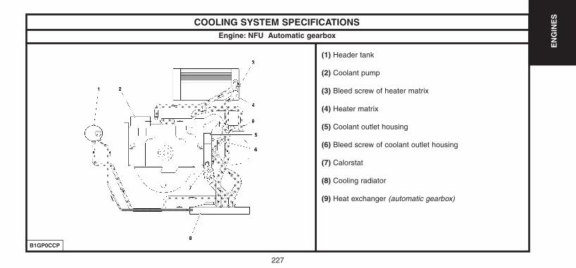
227
EN
GIN
ES
COOLING SYSTEM SPECIFICATIONS
B1GP0CCP
(1) Header tank
(2) Coolant pump
(3) Bleed screw of heater matrix
(4) Heater matrix
(5) Coolant outlet housing
(6) Bleed screw of coolant outlet housing
(7) Calorstat
(8) Cooling radiator
(9) Heat exchanger (automatic gearbox)
Engine: NFU Automatic gearbox
UK-C4-page131-237-2004 15/11/04 9:19 Page 227

228
EN
GIN
ES
COOLING SYSTEM SPECIFICATIONS
B1GP0CAP
(1) Heater matrix
(2) Bleed screw
(3) Cylinder block drain screw
(4) Coolant outlet housing with piloted thermostatic regulator
(5) Cooling radiator
(6) Header tank
(7) Coolant pump
(8) Coolant/oil exchanger (engine)
(9) Coolant/oil exchanger (automatic gearbox)
Engine: RFJ
UK-C4-page131-237-2004 15/11/04 9:19 Page 228
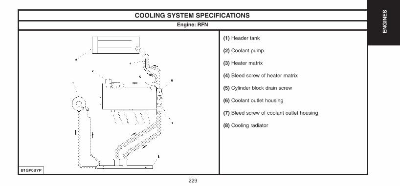
229
EN
GIN
ES
COOLING SYSTEM SPECIFICATIONS
B1GP0BYP
(1) Header tank
(2) Coolant pump
(3) Heater matrix
(4) Bleed screw of heater matrix
(5) Cylinder block drain screw
(6) Coolant outlet housing
(7) Bleed screw of coolant outlet housing
(8) Cooling radiator
Engine: RFN
UK-C4-page131-237-2004 15/11/04 9:19 Page 229

230
EN
GIN
ES
COOLING SYSTEM SPECIFICATIONS
B1GP0BUP
(1) Header tank
(2) Coolant pump
(3) Heater matrix
(4) Bleed screw of heater matrix
(5) Cylinder block drain screw
(6) Coolant outlet housing
(7) Bleed screw of coolant outlet housing
(8) Cooling radiator
(9) Coolant/oil exchanger
Engine: RFK
UK-C4-page131-237-2004 15/11/04 9:19 Page 230
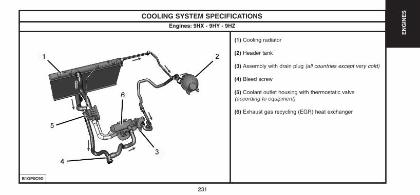
231
EN
GIN
ES
COOLING SYSTEM SPECIFICATIONS
B1GP0C9D
(1) Cooling radiator
(2) Header tank
(3) Assembly with drain plug (all countries except very cold)
(4) Bleed screw
(5) Coolant outlet housing with thermostatic valve(according to equipment)
(6) Exhaust gas recycling (EGR) heat exchanger
Engines: 9HX - 9HY - 9HZ
UK-C4-page131-237-2004 15/11/04 9:19 Page 231
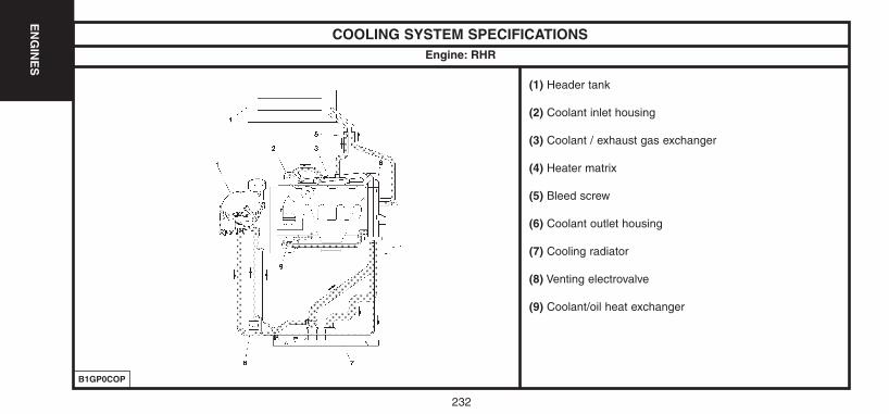
232
EN
GIN
ES
COOLING SYSTEM SPECIFICATIONS
B1GP0COP
(1) Header tank
(2) Coolant inlet housing
(3) Coolant / exhaust gas exchanger
(4) Heater matrix
(5) Bleed screw
(6) Coolant outlet housing
(7) Cooling radiator
(8) Venting electrovalve
(9) Coolant/oil heat exchanger
Engine: RHR
UK-C4-page131-237-2004 15/11/04 9:19 Page 232
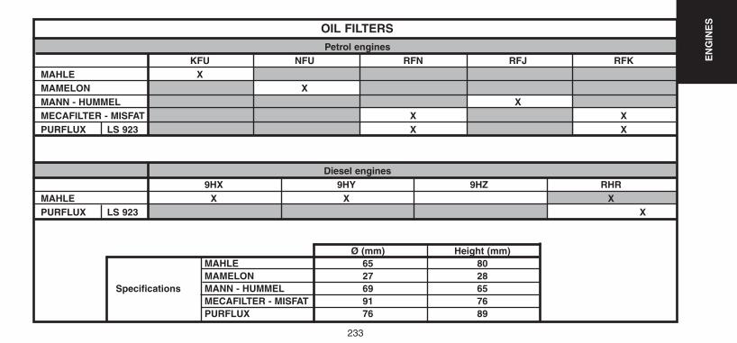
233
EN
GIN
ES
OIL FILTERSPetrol engines
KFU NFU RFN RFJ RFKMAHLE XMAMELON XMANN - HUMMEL XMECAFILTER - MISFAT X XPURFLUX LS 923 X X
Diesel engines9HX 9HY 9HZ RHR
MAHLE X X XPURFLUX LS 923 X
Ø (mm) Height (mm)MAHLE 65 80MAMELON 27 28
Specifications MANN - HUMMEL 69 65MECAFILTER - MISFAT 91 76PURFLUX 76 89
UK-C4-page131-237-2004 15/11/04 9:19 Page 233
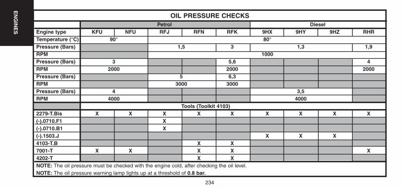
234
EN
GIN
ES
OIL PRESSURE CHECKSPetrol Diesel
Engine type KFU NFU RFJ RFN RFK 9HX 9HY 9HZ RHRTemperature (°C) 90° 80°Pressure (Bars) 1,5 3 1,3 1,9RPM 1000Pressure (Bars) 3 5,6 4RPM 2000 2000 2000Pressure (Bars) 5 6,3RPM 3000 3000Pressure (Bars) 4 3,5RPM 4000 4000
Tools (Toolkit 4103)2279-T.Bis X X X X X X X X X(-).0710.F1 X(-).0710.B1 X(-).1503.J X X X4103-T.B X X7001-T X X X X X4202-T X XNOTE: The oil pressure must be checked with the engine cold, after checking the oil level.NOTE: The oil pressure warning lamp lights up at a threshold of 0.8 bar.
UK-C4-page131-237-2004 15/11/04 9:19 Page 234
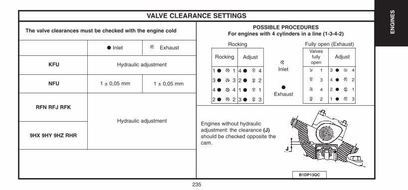
235
EN
GIN
ES
VALVE CLEARANCE SETTINGS
The valve clearances must be checked with the engine cold
● Inlet
KFU
NFU
RFN RFJ RFK
9HX 9HY 9HZ RHR
Exhaust
Hydraulic adjustment
1 ± 0,05 mm 1 ± 0,05 mm
Rocking Adjust
1 ● 1
3 ● 3
4 ● 4
2 ● 2
4 ● 4
2 ● 2
1 ● 1
3 ● 3
Inlet
●
Exhaust
RockingValves
fully open
Adjust
1
3
4
2
3 ● 4
4 ● 2
2 ● 1
1 ● 3
Fully open (Exhaust)
POSSIBLE PROCEDURESFor engines with 4 cylinders in a line (1-3-4-2)
Engines without hydraulicadjustment: the clearance (J)should be checked opposite thecam.
B1DP13QC
Hydraulic adjustment
UK-C4-page131-237-2004 15/11/04 9:19 Page 235

236
EN
GIN
ES
FILLING AND BLEEDING THE COOLING CIRCUIT
Tools.
[1] Filling cylinder : 4520-T[2] Adaptor for filling cylinder : 4222-T[3] Control rod for filling cylinder : 4370-T
IMPERATIVE: Respect the safety and cleanliness requirements.
The draining and refilling operations can be carried out using coolant fluidreplacement equipment.It is essential to follow the instructions as stated for that equipment.
Draining.Remove the header tank cap.Uncouple the radiator bottom hose.Remove the drain screw from the cylinder block.
Filling and bleeding.Open the bleed screws of the following components:- Heater matrix outlet.- Coolant outlet housing.Connect the radiator bottom hose.Fit the drain screw on the cylinder block (screw equipped with a new seal).Tighten to 3 ± 0,3 m.daN.
B1GP00AC
Engines: KFU - NFU - RFJ - RFN - RFK - RHR
E5AP2CNCE5AP1GNC
UK-C4-page131-237-2004 15/11/04 9:19 Page 236
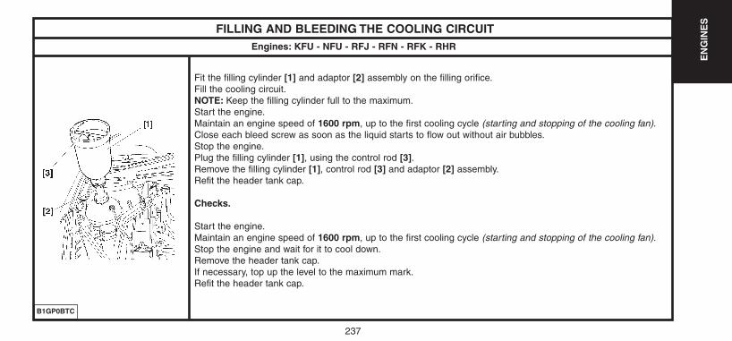
237
EN
GIN
ES
FILLING AND BLEEDING THE COOLING CIRCUIT
Fit the filling cylinder [1] and adaptor [2] assembly on the filling orifice.Fill the cooling circuit.NOTE: Keep the filling cylinder full to the maximum.Start the engine.Maintain an engine speed of 1600 rpm, up to the first cooling cycle (starting and stopping of the cooling fan).Close each bleed screw as soon as the liquid starts to flow out without air bubbles.Stop the engine.Plug the filling cylinder [1], using the control rod [3].Remove the filling cylinder [1], control rod [3] and adaptor [2] assembly.Refit the header tank cap.
Checks.
Start the engine.Maintain an engine speed of 1600 rpm, up to the first cooling cycle (starting and stopping of the cooling fan).Stop the engine and wait for it to cool down.Remove the header tank cap.If necessary, top up the level to the maximum mark.Refit the header tank cap.
B1GP0BTC
Engines: KFU - NFU - RFJ - RFN - RFK - RHR
UK-C4-page131-237-2004 15/11/04 9:19 Page 237
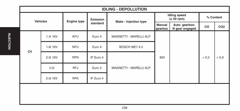
238
INJE
CT
ION
1.4i 16V KFU Euro 4 MAGNETTI - MARELLI 6LP
1.6i 16V NFU Euro 4 BOSCH ME7.4.5
2.0i 16V RFN IF Euro 4 850 < 0,5 > 0,9
2.0i RFJ Euro 4 MAGNETTI - MARELLI 6LP
2.0i 16V RFK IF Euro 4
IDLING - DEPOLLUTION
Vehicles Engine typeEmissionstandard Make - Injection type
% Content
CO CO2
Idling speed (± 50 rpm)
Manualgearbox
Auto. gearbox:N gear engaged
C4
UK-C4-page238-270-2004 15/11/04 9:17 Page 238
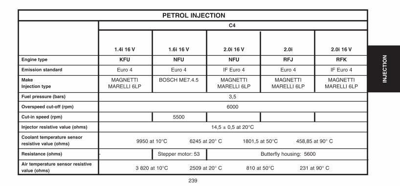
239
INJE
CT
IONEngine type
Emission standard
Make Injection type
Fuel pressure (bars)
Overspeed cut-off (rpm)
Cut-in speed (rpm)
Injector resistive value (ohms)
Coolant temperature sensorresistive value (ohms)
Resistance (ohms)
Air temperature sensor resistivevalue (ohms)
PETROL INJECTIONC4
1.4i 16 V 1.6i 16 V 2.0i 16 V 2.0i 2.0i 16 V
KFU NFU NFU RFJ RFK
Euro 4 Euro 4 IF Euro 4 Euro 4 IF Euro 4
MAGNETTI BOSCH ME7.4.5 MAGNETTI MAGNETTI MAGNETTIMARELLI 6LP MARELLI 6LP MARELLI 6LP MARELLI 6LP
3,5
6000
5500
14,5 ± 0,5 at 20°C
9950 at 10°C 6245 at 20° C 1801,5 at 50°C 458,85 at 90° C
- Stepper motor: 53 Butterfly housing: 5600
3 820 at 10°C 2509 at 20° C 810 at 50°C 231 at 90° C
UK-C4-page238-270-2004 15/11/04 9:17 Page 239
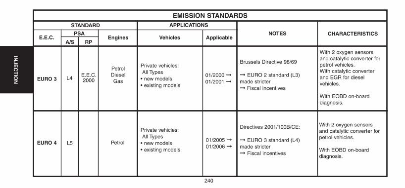
STANDARD
EMISSION STANDARDS
PSA
A/S RPEngines ApplicableVehicles
EURO 3
EURO 4 L5 Petrol
E.E.C.
APPLICATIONS
NOTES CHARACTERISTICS
Petrol Diesel Gas
L4E.E.C.2000
With 2 oxygen sensorsand catalytic converter forpetrol vehicles.With catalytic converterand EGR for dieselvehicles.
With EOBD on-board diagnosis.
Private vehicles:All Types
• new models • existing models
Private vehicles:All Types
• new models • existing models
01/2000 ➞01/2001 ➞
01/2005 ➞01/2006 ➞
Brussels Directive 98/69
➞ EURO 2 standard (L3)made stricter➞ Fiscal incentives
Directives 2001/100B/CE:
➞ EURO 3 standard (L4) made stricter➞ Fiscal incentives
240
INJE
CT
ION
With 2 oxygen sensorsand catalytic converter forpetrol vehicles.
With EOBD on-board diagnosis.
UK-C4-page238-270-2004 15/11/04 9:17 Page 240
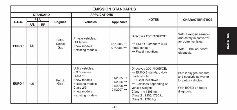
241
INJE
CT
ION
STANDARD
EMISSION STANDARDS
PSA
A/S RPEngines ApplicableVehicles
EURO 3
EURO 4 L5Petrol Gas
E.E.C.
APPLICATIONS
NOTES CHARACTERISTICS
Petrol DieselGas
L5
With 2 oxygen sensorsand catalytic converterfor petrol vehicles.
With EOBD on-board diagnosis.
Private vehicles:All Types
• new models • existing models
Utility vehicles:< 3.5 tonnes Class 1:• new models • existing modelsClass 2/3:• new models • existing models
01/2005 ➞01/2006 ➞
01/2005 ➞01/2006 ➞01/2006 ➞01/2007 ➞
Directives 2001/100B/CE:
➞ EURO 3 standard (L4) made stricter➞ Fiscal incentives
Directives 2001/100B/CE:➞ EURO 3 standard (L4) made stricter➞ Fiscal incentives➞ 3 classes depending onvehicle weight:Class 1 < 1305 kg Class 2 : 1305/1760 kg Class 3 : 1760 kg
With 2 oxygen sensorsand catalytic converterfor petrol vehicles.
With EOBD on-board diagnosis.
UK-C4-page238-270-2004 15/11/04 9:17 Page 241
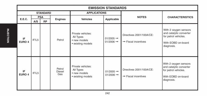
242
INJE
CT
ION
STANDARD
EMISSION STANDARDS
PSA
A/S RPEngines ApplicableVehicles
IFEURO 4
IFEURO 4 IF/L5
Petrol DieselGas
E.E.C.
APPLICATIONS
NOTES CHARACTERISTICS
Petrol IF/L5
With 2 oxygen sensorsand catalytic converter for petrol vehicles.
With EOBD on-board diagnosis.
Private vehicles:All Types
• new models • existing models
Private vehicles:All Types
• new models • existing models
01/2005 ➞01/2006 ➞
01/2005 ➞01/2006 ➞
Directives 2001/100A/CE:
➞ Fiscal incentives
Directives 2001/100A/CE:
➞ Fiscal incentives
With 2 oxygen sensorsand catalytic converter for petrol vehicles.
With EOBD on-board diagnosis.
UK-C4-page238-270-2004 15/11/04 9:17 Page 242
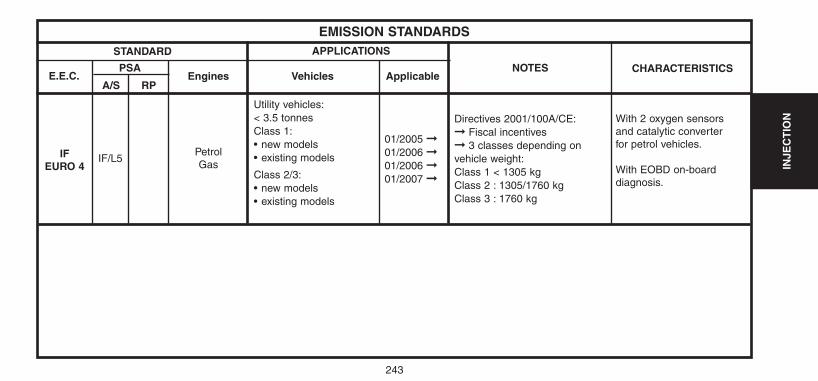
243
INJE
CT
ION
STANDARD
EMISSION STANDARDS
PSA
A/S RPEngines ApplicableVehicles
IFEURO 4
E.E.C.
APPLICATIONS
NOTES CHARACTERISTICS
Petrol Gas
IF/L5
With 2 oxygen sensorsand catalytic converter for petrol vehicles.
With EOBD on-board diagnosis.
Utility vehicles:< 3.5 tonnes Class 1:• new models • existing models
Class 2/3:• new models • existing models
01/2005 ➞01/2006 ➞01/2006 ➞01/2007 ➞
Directives 2001/100A/CE:➞ Fiscal incentives➞ 3 classes depending onvehicle weight:Class 1 < 1305 kg Class 2 : 1305/1760 kg Class 3 : 1760 kg
UK-C4-page238-270-2004 15/11/04 9:17 Page 243
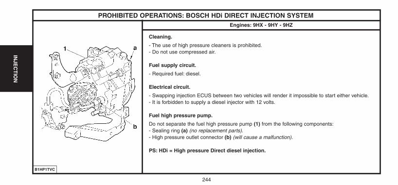
244
INJE
CT
ION
PROHIBITED OPERATIONS: BOSCH HDi DIRECT INJECTION SYSTEMEngines: 9HX - 9HY - 9HZ
Cleaning.
- The use of high pressure cleaners is prohibited.- Do not use compressed air.
Fuel supply circuit.
- Required fuel: diesel.
Electrical circuit.
- Swapping injection ECUS between two vehicles will render it impossible to start either vehicle.- It is forbidden to supply a diesel injector with 12 volts.
Fuel high pressure pump.
Do not separate the fuel high pressure pump (1) from the following components:- Sealing ring (a) (no replacement parts).- High pressure outlet connector (b) (will cause a malfunction).
PS: HDi = High pressure Direct diesel injection.
B1HP1TVC
UK-C4-page238-270-2004 15/11/04 9:17 Page 244
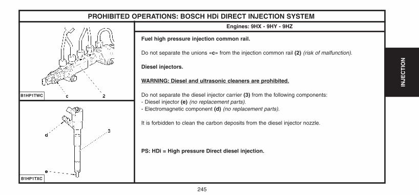
245
INJE
CT
ION
PROHIBITED OPERATIONS: BOSCH HDi DIRECT INJECTION SYSTEMEngines: 9HX - 9HY - 9HZ
Fuel high pressure injection common rail.
Do not separate the unions «c» from the injection common rail (2) (risk of malfunction).
Diesel injectors.
WARNING: Diesel and ultrasonic cleaners are prohibited.
Do not separate the diesel injector carrier (3) from the following components:- Diesel injector (e) (no replacement parts).- Electromagnetic component (d) (no replacement parts).
It is forbidden to clean the carbon deposits from the diesel injector nozzle.
PS: HDi = High pressure Direct diesel injection.
B1HP1TXC
B1HP1TWC
UK-C4-page238-270-2004 15/11/04 9:17 Page 245
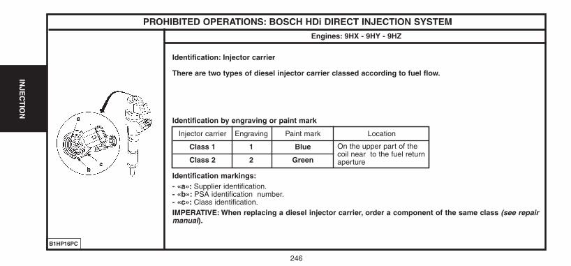
246
INJE
CT
ION
PROHIBITED OPERATIONS: BOSCH HDi DIRECT INJECTION SYSTEMEngines: 9HX - 9HY - 9HZ
Identification: Injector carrier
There are two types of diesel injector carrier classed according to fuel flow.
Identification by engraving or paint mark
Identification markings:- «a»: Supplier identification.- «b»: PSA identification number.- «c»: Class identification.IMPERATIVE: When replacing a diesel injector carrier, order a component of the same class (see repairmanual).
B1HP16PC
Injector carrier
Class 1
Class 2
Engraving
1
2
Paint mark
Blue
Green
Location
On the upper part of thecoil near to the fuel returnaperture
UK-C4-page238-270-2004 15/11/04 9:17 Page 246
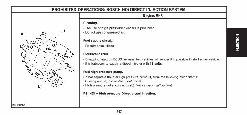
INJE
CT
ION
247
PROHIBITED OPERATIONS: BOSCH HDi DIRECT INJECTION SYSTEMEngine: RHR
Cleaning.
- The use of high pressure cleaners is prohibited.- Do not use compressed air.
Fuel supply circuit.
- Required fuel: diesel.
Electrical circuit.
- Swapping injection ECUS between two vehicles will render it impossible to start either vehicle.- It is forbidden to supply a diesel injector with 12 volts.
Fuel high pressure pump.
Do not separate the fuel high pressure pump (1) from the following components:- Sealing ring (a) (no replacement parts).- High pressure outlet connector (b) (will cause a malfunction).
PS: HDi = High pressure Direct diesel injection.
B1HP1K9C
UK-C4-page238-270-2004 15/11/04 9:17 Page 247
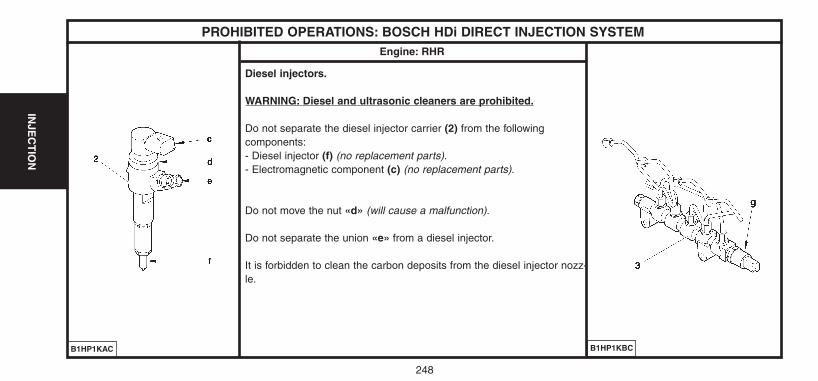
248
INJE
CT
ION
PROHIBITED OPERATIONS: BOSCH HDi DIRECT INJECTION SYSTEMEngine: RHR
Diesel injectors.
WARNING: Diesel and ultrasonic cleaners are prohibited.
Do not separate the diesel injector carrier (2) from the following components:- Diesel injector (f) (no replacement parts).- Electromagnetic component (c) (no replacement parts).
Do not move the nut «d» (will cause a malfunction).
Do not separate the union «e» from a diesel injector.
It is forbidden to clean the carbon deposits from the diesel injector nozz-le.
B1HP1KAC B1HP1KBC
UK-C4-page238-270-2004 15/11/04 9:17 Page 248
249
INJE
CT
ION
SAFETY REQUIREMENTS: HDi DIRECT INJECTION SYSTEMEngines: 9HX – 9HY – 9HZ – RHR
SAFETY REQUIREMENTS.
Preamble.All interventions on the injection system must be carried out to conform with the following requirements and regulations:- Competent health authorities.- Accident prevention.- Environmental protection.WARNING: Repairs must be carried out by specialised personnel informed of the safety requirements and of the precautions to be taken.
Safety requirements.IMPERATIVE: Take into account the very high pressures in the high pressure fuel circuit (1350 bars), and respectthe requirements below:- No smoking in proximity to the high pressure circuit when work is being carried out.- Avoid working close to flame or sparks.
Engine running:- Do not work on the high pressure fuel circuit.- Always stay clear of the trajectory of any possible jet of fuel, which could cause serious injuries.- Do not place your hand close to any leak in the high pressure fuel circuit.After the engine has stopped, wait 30 seconds before any intervention.NOTE: This waiting time is necessary in order to allow the high pressure fuel circuit to return to atmospheric pressure.
UK-C4-page238-270-2004 15/11/04 9:17 Page 249
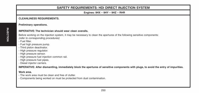
250
INJE
CT
ION
SAFETY REQUIREMENTS: HDi DIRECT INJECTION SYSTEMEngines: 9HX – 9HY – 9HZ – RHR
CLEANLINESS REQUIREMENTS.
Preliminary operations.
IMPERATIVE: The technician should wear clean overalls.
Before working on the injection system, it may be necessary to clean the apertures of the following sensitive components:(refer to corresponding procedures)- Fuel filter.- Fuel high pressure pump.- Third piston deactivator.- High pressure regulator.- High pressure sensor.- High pressure fuel injection common rail.- High pressure fuel pipes.- Diesel injector carriers.
IMPERATIVE: After dismantling, immediately block the apertures of sensitive components with plugs, to avoid the entry of impurities.
Work area.- The work area must be clean and free of clutter.- Components being worked on must be protected from dust contamination.
UK-C4-page238-270-2004 15/11/04 9:17 Page 250
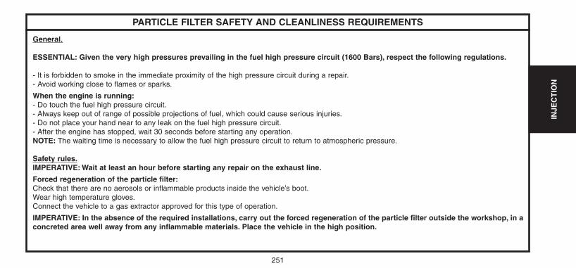
251
INJE
CT
ION
PARTICLE FILTER SAFETY AND CLEANLINESS REQUIREMENTS
General.
ESSENTIAL: Given the very high pressures prevailing in the fuel high pressure circuit (1600 Bars), respect the following regulations.
- It is forbidden to smoke in the immediate proximity of the high pressure circuit during a repair.- Avoid working close to flames or sparks.
When the engine is running:- Do touch the fuel high pressure circuit.- Always keep out of range of possible projections of fuel, which could cause serious injuries.- Do not place your hand near to any leak on the fuel high pressure circuit.- After the engine has stopped, wait 30 seconds before starting any operation.NOTE: The waiting time is necessary to allow the fuel high pressure circuit to return to atmospheric pressure.
Safety rules.IMPERATIVE: Wait at least an hour before starting any repair on the exhaust line.
Forced regeneration of the particle filter:Check that there are no aerosols or inflammable products inside the vehicle’s boot.Wear high temperature gloves.Connect the vehicle to a gas extractor approved for this type of operation.
IMPERATIVE: In the absence of the required installations, carry out the forced regeneration of the particle filter outside the workshop, in aconcreted area well away from any inflammable materials. Place the vehicle in the high position.
UK-C4-page238-270-2004 15/11/04 9:17 Page 251
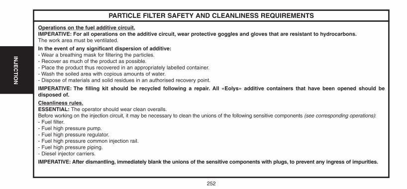
252
INJE
CT
ION
PARTICLE FILTER SAFETY AND CLEANLINESS REQUIREMENTS
Operations on the fuel additive circuit.IMPERATIVE: For all operations on the additive circuit, wear protective goggles and gloves that are resistant to hydrocarbons.The work area must be ventilated.
In the event of any significant dispersion of additive:- Wear a breathing mask for filtering the particles.- Recover as much of the product as possible.- Place the product thus recovered in an appropriately labelled container.- Wash the soiled area with copious amounts of water.- Dispose of materials and solid residues in an authorised recovery point.
IMPERATIVE: The filling kit should be recycled following a repair. All «Eolys» additive containers that have been opened should bedisposed of.
Cleanliness rules.ESSENTIAL: The operator should wear clean overalls.Before working on the injection circuit, it may be necessary to clean the unions of the following sensitive components (see corresponding operations):- Fuel filter.- Fuel high pressure pump.- Fuel high pressure regulator.- Fuel high pressure common injection rail.- Fuel high pressure piping.- Diesel injector carriers.
IMPERATIVE: After dismantling, immediately blank the unions of the sensitive components with plugs, to prevent any ingress of impurities.
UK-C4-page238-270-2004 15/11/04 9:17 Page 252
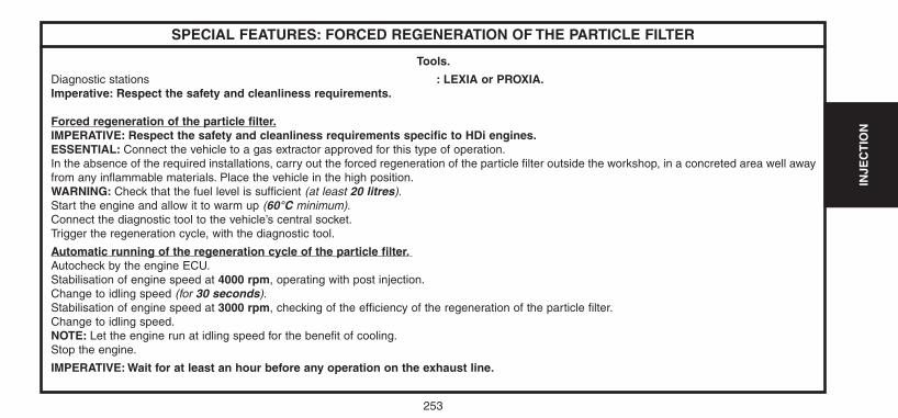
253
INJE
CT
ION
SPECIAL FEATURES: FORCED REGENERATION OF THE PARTICLE FILTER
Tools.
Diagnostic stations : LEXIA or PROXIA.Imperative: Respect the safety and cleanliness requirements.
Forced regeneration of the particle filter.IMPERATIVE: Respect the safety and cleanliness requirements specific to HDi engines.ESSENTIAL: Connect the vehicle to a gas extractor approved for this type of operation.In the absence of the required installations, carry out the forced regeneration of the particle filter outside the workshop, in a concreted area well awayfrom any inflammable materials. Place the vehicle in the high position.WARNING: Check that the fuel level is sufficient (at least 20 litres).Start the engine and allow it to warm up (60°C minimum).Connect the diagnostic tool to the vehicle’s central socket.Trigger the regeneration cycle, with the diagnostic tool.
Automatic running of the regeneration cycle of the particle filter.Autocheck by the engine ECU.Stabilisation of engine speed at 4000 rpm, operating with post injection.Change to idling speed (for 30 seconds).Stabilisation of engine speed at 3000 rpm, checking of the efficiency of the regeneration of the particle filter.Change to idling speed.NOTE: Let the engine run at idling speed for the benefit of cooling.Stop the engine.
IMPERATIVE: Wait for at least an hour before any operation on the exhaust line.
UK-C4-page238-270-2004 15/11/04 9:17 Page 253
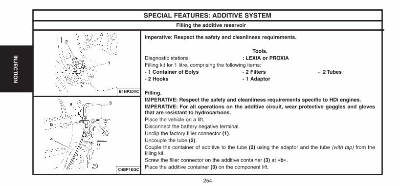
254
INJE
CT
ION
SPECIAL FEATURES: ADDITIVE SYSTEM
Imperative: Respect the safety and cleanliness requirements.
Tools.Diagnostic stations : LEXIA or PROXIAFilling kit for 1 litre, comprising the following items:- 1 Container of Eolys - 2 Filters - 2 Tubes- 2 Hooks - 1 Adaptor
Filling.IMPERATIVE: Respect the safety and cleanliness requirements specific to HDi engines.IMPERATIVE: For all operations on the additive circuit, wear protective goggles and glovesthat are resistant to hydrocarbons.Place the vehicle on a lift.Disconnect the battery negative terminal.Unclip the factory filler connector (1).Uncouple the tube (2).Couple the container of additive to the tube (2) using the adaptor and the tube (with tap) from thefilling kit.Screw the filler connector on the additive container (3) at «b».Place the additive container (3) on the component lift.
B1HP20VC
C4BP1EGC
Filling the additive reservoir
UK-C4-page238-270-2004 15/11/04 9:17 Page 254
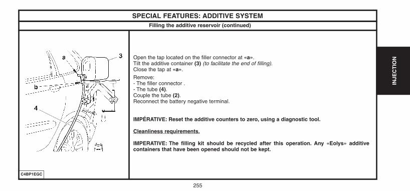
255
INJE
CT
ION
SPECIAL FEATURES: ADDITIVE SYSTEM
Open the tap located on the filler connector at «a».Tilt the additive container (3) (to facilitate the end of filling).Close the tap at «a».
Remove:- The filler connector .- The tube (4).Couple the tube (2).Reconnect the battery negative terminal.
IMPÉRATIVE: Reset the additive counters to zero, using a diagnostic tool.
Cleanliness requirements.
IMPERATIVE: The filling kit should be recycled after this operation. Any «Eolys» additivecontainers that have been opened should not be kept.
C4BP1EGC
Filling the additive reservoir (continued)
UK-C4-page238-270-2004 15/11/04 9:17 Page 255
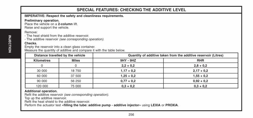
256
INJE
CT
ION
SPECIAL FEATURES: CHECKING THE ADDITIVE LEVELIMPERATIVE: Respect the safety and cleanliness requirements.Preliminary operation.Place the vehicle on a 2-column lift.Raise and support the vehicle.Remove:- The heat shield from the additive reservoir.- The additive reservoir (see corresponding operation).Checks.Empty the reservoir into a clean glass container.Measure the quantity of additive and compare it with the table below.
Additional operation.Refit the additive reservoir (see corresponding operation).Top up the additive reservoir.Refit the heat shield to the additive reservoir.Perform the actuator test «filling the tube: additive pump - additive injector» using LEXIA or PROXIA.
Distance travelled by the vehicle Quantity of additive taken from the additive reservoir (Litres)
Kilometres Miles 9HY - 9HZ RHR
0 0 2,2 + 0,2 2,8 + 0,2
30 000 18 750 1,17 + 0,2 2,17 + 0,2
60 000 37 500 1,25 + 0,2 1,55 + 0,2
90 000 56 250 0,77 + 0,2 0,92 + 0,2
120 000 75 000 0,3 + 0,2 0,3 + 0,2
UK-C4-page238-270-2004 15/11/04 9:17 Page 256
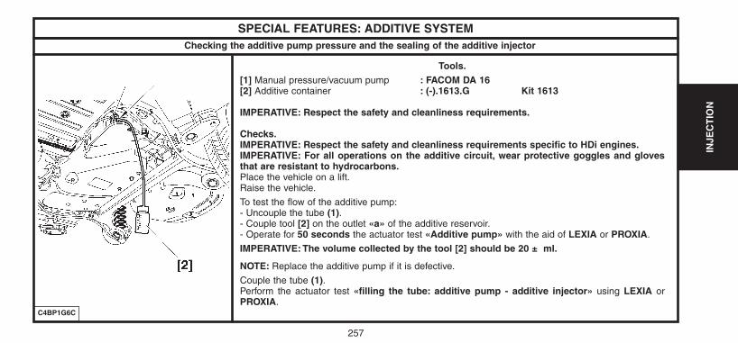
257
INJE
CT
ION
SPECIAL FEATURES: ADDITIVE SYSTEM
Tools.[1] Manual pressure/vacuum pump : FACOM DA 16[2] Additive container : (-).1613.G Kit 1613
IMPERATIVE: Respect the safety and cleanliness requirements.
Checks.IMPERATIVE: Respect the safety and cleanliness requirements specific to HDi engines.IMPERATIVE: For all operations on the additive circuit, wear protective goggles and glovesthat are resistant to hydrocarbons.Place the vehicle on a lift.Raise the vehicle.
To test the flow of the additive pump:- Uncouple the tube (1).- Couple tool [2] on the outlet «a» of the additive reservoir.- Operate for 50 seconds the actuator test «Additive pump» with the aid of LEXIA or PROXIA.
IMPERATIVE: The volume collected by the tool [2] should be 20 ± ml.
NOTE: Replace the additive pump if it is defective.
Couple the tube (1).Perform the actuator test «filling the tube: additive pump - additive injector» using LEXIA orPROXIA.
C4BP1G6C
Checking the additive pump pressure and the sealing of the additive injector
UK-C4-page238-270-2004 15/11/04 9:17 Page 257
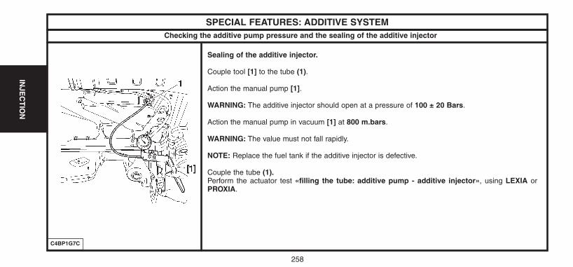
258
INJE
CT
ION
SPECIAL FEATURES: ADDITIVE SYSTEM
Sealing of the additive injector.
Couple tool [1] to the tube (1).
Action the manual pump [1].
WARNING: The additive injector should open at a pressure of 100 ± 20 Bars.
Action the manual pump in vacuum [1] at 800 m.bars.
WARNING: The value must not fall rapidly.
NOTE: Replace the fuel tank if the additive injector is defective.
Couple the tube (1).Perform the actuator test «filling the tube: additive pump - additive injector», using LEXIA orPROXIA.
C4BP1G7C
Checking the additive pump pressure and the sealing of the additive injector
UK-C4-page238-270-2004 15/11/04 9:17 Page 258
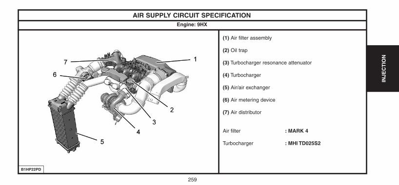
259
INJE
CT
ION
AIR SUPPLY CIRCUIT SPECIFICATION
B1HP22PD
(1) Air filter assembly
(2) Oil trap
(3) Turbocharger resonance attenuator
(4) Turbocharger
(5) Air/air exchanger
(6) Air metering device
(7) Air distributor
Air filter : MARK 4
Turbocharger : MHI TD025S2
Engine: 9HX
UK-C4-page238-270-2004 15/11/04 9:17 Page 259
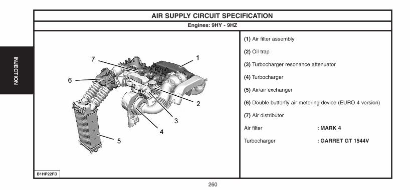
260
INJE
CT
ION
AIR SUPPLY CIRCUIT SPECIFICATION
B1HP22FD
(1) Air filter assembly
(2) Oil trap
(3) Turbocharger resonance attenuator
(4) Turbocharger
(5) Air/air exchanger
(6) Double butterfly air metering device (EURO 4 version)
(7) Air distributor
Air filter : MARK 4
Turbocharger : GARRET GT 1544V
Engines: 9HY - 9HZ
UK-C4-page238-270-2004 15/11/04 9:17 Page 260
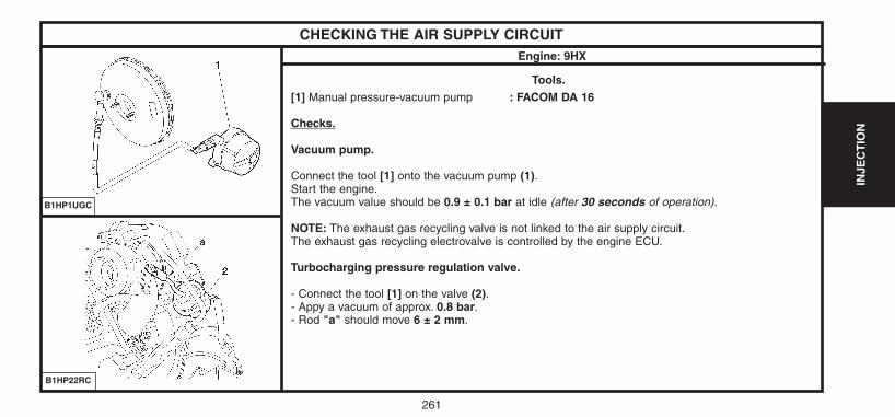
261
INJE
CT
ION
CHECKING THE AIR SUPPLY CIRCUIT
Tools.[1] Manual pressure-vacuum pump : FACOM DA 16
Checks.
Vacuum pump.
Connect the tool [1] onto the vacuum pump (1).Start the engine.The vacuum value should be 0.9 ± 0.1 bar at idle (after 30 seconds of operation).
NOTE: The exhaust gas recycling valve is not linked to the air supply circuit.The exhaust gas recycling electrovalve is controlled by the engine ECU.
Turbocharging pressure regulation valve.
- Connect the tool [1] on the valve (2).- Appy a vacuum of approx. 0.8 bar.- Rod "a" should move 6 ± 2 mm.
B1HP1UGC
B1HP22RC
Engine: 9HX
UK-C4-page238-270-2004 15/11/04 9:18 Page 261
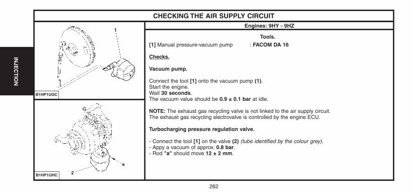
262
INJE
CT
ION
CHECKING THE AIR SUPPLY CIRCUIT
Tools.[1] Manual pressure-vacuum pump : FACOM DA 16
Checks.
Vacuum pump.
Connect the tool [1] onto the vacuum pump (1).Start the engine.Wait 30 seconds.The vacuum value should be 0.9 ± 0.1 bar at idle.
NOTE: The exhaust gas recycling valve is not linked to the air supply circuit.The exhaust gas recycling electrovalve is controlled by the engine ECU.
Turbocharging pressure regulation valve.
- Connect the tool [1] on the valve (2) (tube identified by the colour grey).- Appy a vacuum of approx. 0.8 bar.- Rod "a" should move 12 ± 2 mm.
B1HP1UGC
B1HP1UHC
Engines: 9HY - 9HZ
UK-C4-page238-270-2004 15/11/04 9:18 Page 262
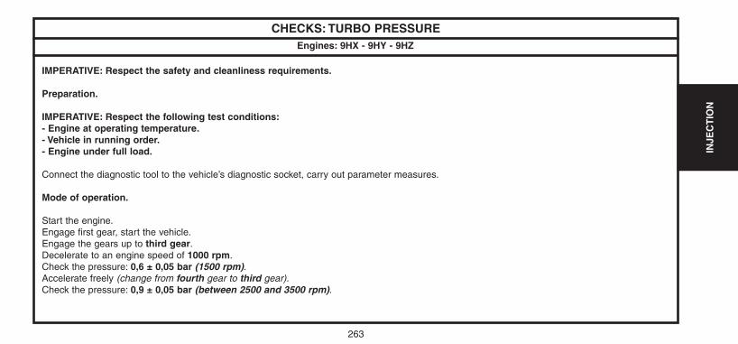
263
INJE
CT
ION
CHECKS: TURBO PRESSURE
IMPERATIVE: Respect the safety and cleanliness requirements.
Preparation.
IMPERATIVE: Respect the following test conditions:- Engine at operating temperature.- Vehicle in running order.- Engine under full load.
Connect the diagnostic tool to the vehicle’s diagnostic socket, carry out parameter measures.
Mode of operation.
Start the engine.Engage first gear, start the vehicle.Engage the gears up to third gear.Decelerate to an engine speed of 1000 rpm.Check the pressure: 0,6 ± 0,05 bar (1500 rpm).Accelerate freely (change from fourth gear to third gear).Check the pressure: 0,9 ± 0,05 bar (between 2500 and 3500 rpm).
Engines: 9HX - 9HY - 9HZ
UK-C4-page238-270-2004 15/11/04 9:18 Page 263
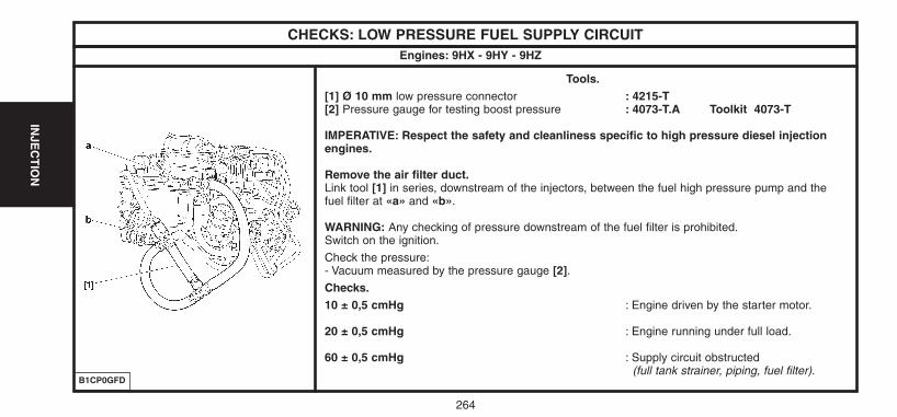
264
INJE
CT
ION
CHECKS: LOW PRESSURE FUEL SUPPLY CIRCUIT
Tools.[1] Ø 10 mm low pressure connector : 4215-T[2] Pressure gauge for testing boost pressure : 4073-T.A Toolkit 4073-T
IMPERATIVE: Respect the safety and cleanliness specific to high pressure diesel injectionengines.
Remove the air filter duct.Link tool [1] in series, downstream of the injectors, between the fuel high pressure pump and thefuel filter at «a» and «b».
WARNING: Any checking of pressure downstream of the fuel filter is prohibited.Switch on the ignition.
Check the pressure:- Vacuum measured by the pressure gauge [2].Checks.10 ± 0,5 cmHg : Engine driven by the starter motor.
20 ± 0,5 cmHg : Engine running under full load.
60 ± 0,5 cmHg : Supply circuit obstructed(full tank strainer, piping, fuel filter).
B1CP0GFD
Engines: 9HX - 9HY - 9HZ
UK-C4-page238-270-2004 15/11/04 9:18 Page 264
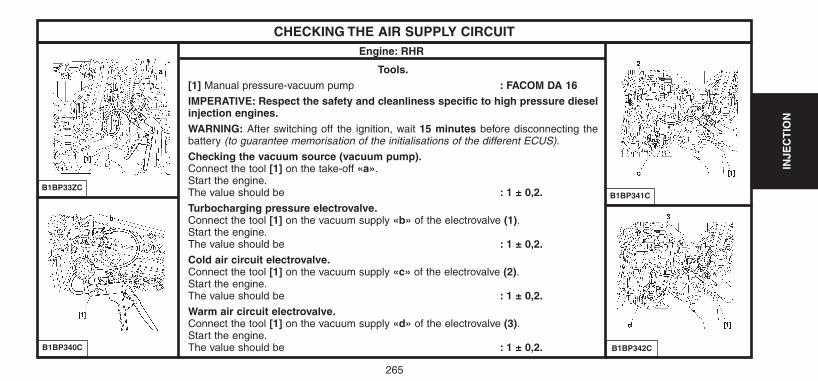
265
INJE
CT
ION
CHECKING THE AIR SUPPLY CIRCUIT
B1BP33ZC
B1BP340C
Engine: RHR
B1BP341C
B1BP342C
Tools.[1] Manual pressure-vacuum pump : FACOM DA 16IMPERATIVE: Respect the safety and cleanliness specific to high pressure dieselinjection engines.WARNING: After switching off the ignition, wait 15 minutes before disconnecting thebattery (to guarantee memorisation of the initialisations of the different ECUS).
Checking the vacuum source (vacuum pump).Connect the tool [1] on the take-off «a».Start the engine.The value should be : 1 ± 0,2.Turbocharging pressure electrovalve.Connect the tool [1] on the vacuum supply «b» of the electrovalve (1).Start the engine.The value should be : 1 ± 0,2.Cold air circuit electrovalve.Connect the tool [1] on the vacuum supply «c» of the electrovalve (2).Start the engine.The value should be : 1 ± 0,2.Warm air circuit electrovalve.Connect the tool [1] on the vacuum supply «d» of the electrovalve (3).Start the engine.The value should be : 1 ± 0,2.
UK-C4-page238-270-2004 15/11/04 9:18 Page 265
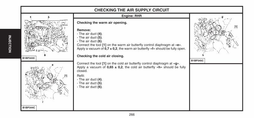
266
INJE
CT
ION
CHECKING THE AIR SUPPLY CIRCUIT
B1BP343C
B1BP344C
Engine: RHR
B1BP345C
Checking the warm air opening.
Remove:- The air duct (4).- The air duct (5).- The air duct (6).Connect the tool [1] on the warm air butterfly control diaphragm at «e».Apply a vacuum of 0,7 ± 0,2, the warm air butterfly «f» should be fully open.
Checking the cold air closing.
Connect the tool [1] on the cold air butterfly control diaphragm at «g».Apply a vacuum of 0,65 ± 0,2, the cold air butterfly «h» should be fully closed.
Refit:- The air duct (4).- The air duct (5).- The air duct (6).
UK-C4-page238-270-2004 15/11/04 9:18 Page 266
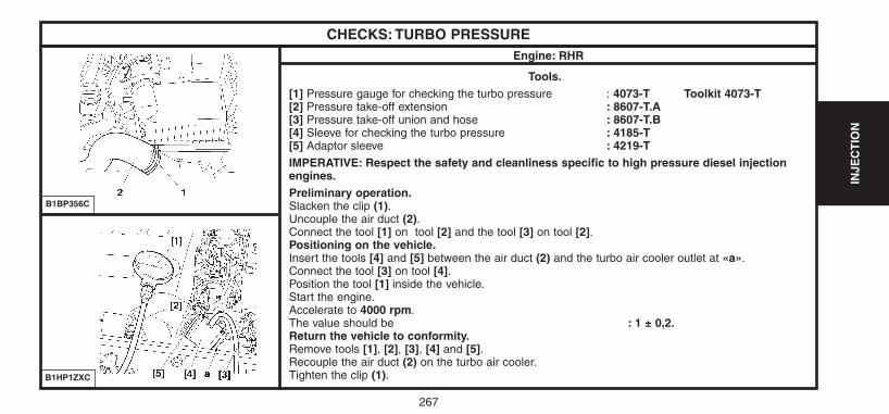
267
INJE
CT
ION
CHECKS: TURBO PRESSURE
Tools.[1] Pressure gauge for checking the turbo pressure : 4073-T Toolkit 4073-T[2] Pressure take-off extension : 8607-T.A[3] Pressure take-off union and hose : 8607-T.B[4] Sleeve for checking the turbo pressure : 4185-T[5] Adaptor sleeve : 4219-TIMPERATIVE: Respect the safety and cleanliness specific to high pressure diesel injectionengines.Preliminary operation.Slacken the clip (1).Uncouple the air duct (2).Connect the tool [1] on tool [2] and the tool [3] on tool [2].Positioning on the vehicle.Insert the tools [4] and [5] between the air duct (2) and the turbo air cooler outlet at «a».Connect the tool [3] on tool [4].Position the tool [1] inside the vehicle.Start the engine.Accelerate to 4000 rpm.The value should be : 1 ± 0,2.Return the vehicle to conformity.Remove tools [1], [2], [3], [4] and [5].Recouple the air duct (2) on the turbo air cooler.Tighten the clip (1).
B1BP356C
B1HP1ZXC
Engine: RHR
UK-C4-page238-270-2004 15/11/04 9:18 Page 267
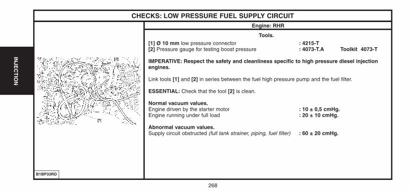
268
INJE
CT
ION
CHECKS: LOW PRESSURE FUEL SUPPLY CIRCUIT
Tools.[1] Ø 10 mm low pressure connector : 4215-T[2] Pressure gauge for testing boost pressure : 4073-T.A Toolkit 4073-T
IMPERATIVE: Respect the safety and cleanliness specific to high pressure diesel injectionengines.
Link tools [1] and [2] in series between the fuel high pressure pump and the fuel filter.
ESSENTIAL: Check that the tool [2] is clean.
Normal vacuum values.Engine driven by the starter motor : 10 ± 0,5 cmHg.Engine running under full load : 20 ± 10 cmHg.
Abnormal vacuum values.Supply circuit obstructed (full tank strainer, piping, fuel filter) : 60 ± 20 cmHg.
B1BP33RD
Engine: RHR
UK-C4-page238-270-2004 15/11/04 9:18 Page 268
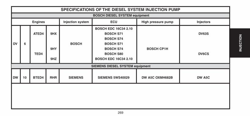
269
INJE
CT
ION
SPECIFICATIONS OF THE DIESEL SYSTEM INJECTION PUMPBOSCH DIESEL SYSTEM equipment
Engines Injection system ECU High pressure pump Injectors
BOSCH EDC 16C34 2.10
ATED4 9HX BOSCH S71 DV63S
BOSCH S74
DV 6 BOSCH BOSCH S71
9HY BOSCH S74 BOSCH CP1H
TED4 BOSCH S80 DV6CS
9HZ BOSCH EDC 16C34 2.10
SIEMENS DIESEL SYSTEM equipment
DW 10 BTED4 RHR SIEMENS SIEMENS 5WS40029 DW A5C OXMH682B DW A5C
UK-C4-page238-270-2004 15/11/04 9:18 Page 269
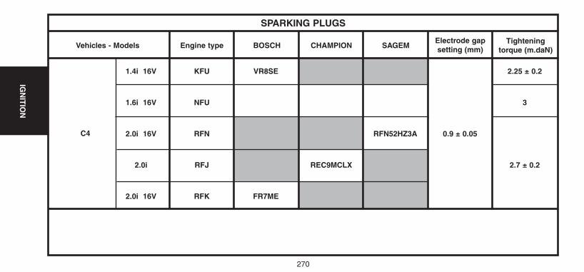
270
IGN
ITIO
N
Vehicles - Models
C4
Engine type BOSCH CHAMPION SAGEMElectrode gapsetting (mm)
Tighteningtorque (m.daN)
1.4i 16V KFU VR8SE 2.25 ± 0.2
1.6i 16V NFU 3
2.0i 16V RFN RFN52HZ3A 0.9 ± 0.05
2.0i RFJ REC9MCLX 2.7 ± 0.2
2.0i 16V RFK FR7ME
SPARKING PLUGS
UK-C4-page238-270-2004 15/11/04 9:18 Page 270
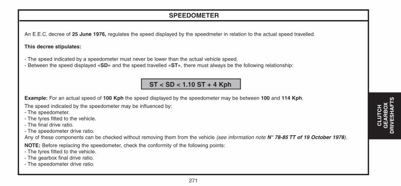
271
CL
UT
CH
GE
AR
BO
XD
RIV
ES
HA
FT
S
SPEEDOMETER
An E.E.C. decree of 25 June 1976, regulates the speed displayed by the speedmeter in relation to the actual speed travelled.
This decree stipulates:
- The speed indicated by a speedometer must never be lower than the actual vehicle speed.- Between the speed displayed «SD» and the speed travelled «ST», there must always be the following relationship:
ST < SD < 1.10 ST + 4 Kph
Example: For an actual speed of 100 Kph the speed displayed by the speedometer may be between 100 and 114 Kph.
The speed indicated by the speedometer may be influenced by:- The speedometer.- The tyres fitted to the vehicle.- The final drive ratio.- The speedometer drive ratio.Any of these components can be checked without removing them from the vehicle (see information note N° 78-85 TT of 19 October 1978).
NOTE: Before replacing the speedometer, check the conformity of the following points:- The tyres fitted to the vehicle.- The gearbox final drive ratio.- The speedometer drive ratio.
UK-C4-page271-321-2004 15/11/04 9:15 Page 271
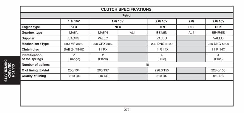
CLUTCH SPECIFICATIONS
Engine type KFU NFU RFN RFJ RFK
Gearbox type MA5/L MA5/N AL4 BE4/5N AL4 BE4R/5S
Supplier SACHS VALEO VALEO VALEO
Mechanism / Type 200 MF 3850 200 CPX 3850 230 DNG 5100 230 DNG 5100
Clutch disc SAE 24/48-8Z 11 RX 11 R 14X 11 R 14X
Identification 2 2 4 4of the springs (Orange) (Black) (Blue) (Blue)
Number of splines 18
Ø of lining. Ext/Int 200/134 200/137 228.6/155 228.6/155
Quality of lining F810 DS 810 DS 810 DS 810 DS
1.4i 16V 1.6i 16V 2.0i 16V 2.0i 2.0i 16V
Petrol
272
CL
UT
CH
GE
AR
BO
XD
RIV
ES
HA
FT
S
UK-C4-page271-321-2004 15/11/04 9:15 Page 272
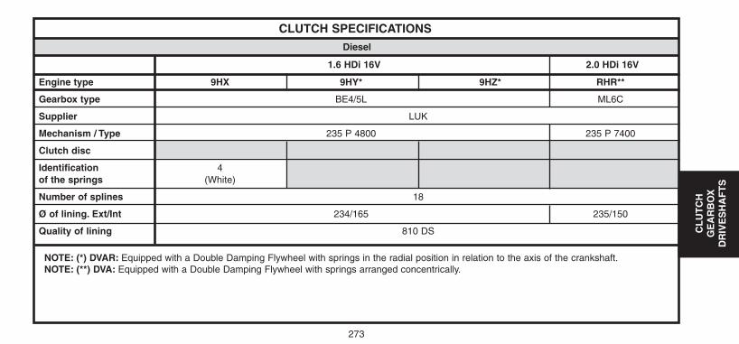
CL
UT
CH
GE
AR
BO
XD
RIV
ES
HA
FT
S
273
NOTE: (*) DVAR: Equipped with a Double Damping Flywheel with springs in the radial position in relation to the axis of the crankshaft.NOTE: (**) DVA: Equipped with a Double Damping Flywheel with springs arranged concentrically.
CLUTCH SPECIFICATIONS
Engine type 9HX 9HY* 9HZ* RHR**
Gearbox type BE4/5L ML6C
Supplier LUK
Mechanism / Type 235 P 4800 235 P 7400
Clutch disc
Identification 4of the springs (White)
Number of splines 18
Ø of lining. Ext/Int 234/165 235/150
Quality of lining 810 DS
1.6 HDi 16V 2.0 HDi 16V
Diesel
UK-C4-page271-321-2004 15/11/04 9:15 Page 273
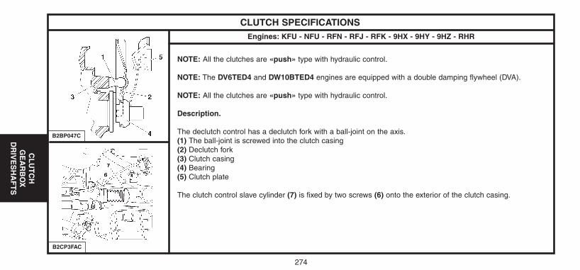
274
CL
UT
CH
GE
AR
BO
XD
RIV
ES
HA
FT
S
CLUTCH SPECIFICATIONSEngines: KFU - NFU - RFN - RFJ - RFK - 9HX - 9HY - 9HZ - RHR
NOTE: All the clutches are «push» type with hydraulic control.
NOTE: The DV6TED4 and DW10BTED4 engines are equipped with a double damping flywheel (DVA).
NOTE: All the clutches are «push» type with hydraulic control.
Description.
The declutch control has a declutch fork with a ball-joint on the axis.(1) The ball-joint is screwed into the clutch casing(2) Declutch fork(3) Clutch casing(4) Bearing(5) Clutch plate
The clutch control slave cylinder (7) is fixed by two screws (6) onto the exterior of the clutch casing.
B2BP047C
B2CP3FAC
UK-C4-page271-321-2004 15/11/04 9:15 Page 274
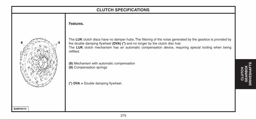
275
CL
UT
CH
GE
AR
BO
XD
RIV
ES
HA
FT
S
CLUTCH SPECIFICATIONS
Features.
The LUK clutch discs have no damper hubs. The filtering of the noise generated by the gearbox is provided bythe double damping flywheel (DVA) (*) and no longer by the clutch disc hub.The LUK clutch mechanism has an automatic compensation device, requiring special tooling when beingrefitted.
(8) Mechanism with automatic compensation(9) Compensation springs
(*) DVA = Double damping flywheel.
B2BP05YC
UK-C4-page271-321-2004 15/11/04 9:15 Page 275
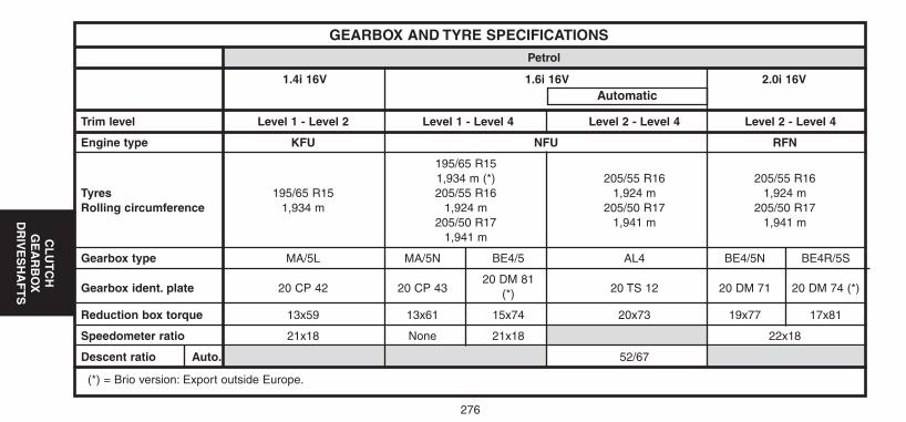
276
CL
UT
CH
GE
AR
BO
XD
RIV
ES
HA
FT
S
(*) = Brio version: Export outside Europe.
GEARBOX AND TYRE SPECIFICATIONS
Trim level Level 1 - Level 2 Level 1 - Level 4 Level 2 - Level 4 Level 2 - Level 4
Engine type KFU NFU RFN
195/65 R151,934 m (*) 205/55 R16 205/55 R16
Tyres 195/65 R15 205/55 R16 1,924 m 1,924 mRolling circumference 1,934 m 1,924 m 205/50 R17 205/50 R17
205/50 R17 1,941 m 1,941 m1,941 m
Gearbox type MA/5L MA/5N BE4/5 AL4 BE4/5N BE4R/5S
Gearbox ident. plate 20 CP 42 20 CP 4320 DM 81
20 TS 12 20 DM 71 20 DM 74 (*)(*)
Reduction box torque 13x59 13x61 15x74 20x73 19x77 17x81
Speedometer ratio 21x18 None 21x18 22x18
Descent ratio Auto. 52/67
1.4i 16V 1.6i 16V 2.0i 16V
Petrol
Automatic
UK-C4-page271-321-2004 15/11/04 9:15 Page 276
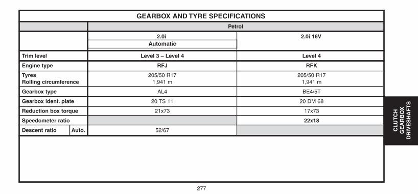
277
CL
UT
CH
GE
AR
BO
XD
RIV
ES
HA
FT
S
GEARBOX AND TYRE SPECIFICATIONS
Trim level Level 3 – Level 4 Level 4
Engine type RFJ RFK
Tyres 205/50 R17 205/50 R17Rolling circumference 1,941 m 1,941 m
Gearbox type AL4 BE4/5T
Gearbox ident. plate 20 TS 11 20 DM 68
Reduction box torque 21x73 17x73
Speedometer ratio 22x18
Descent ratio Auto. 52/67
2.0i 2.0i 16V
Petrol
Automatic
UK-C4-page271-321-2004 15/11/04 9:15 Page 277
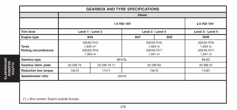
278
CL
UT
CH
GE
AR
BO
XD
RIV
ES
HA
FT
S
(*) = Brio version: Export outside Europe.
GEARBOX AND TYRE SPECIFICATIONS
Trim level Level 1 - Level 3 Level 2 - Level 4 Level 3 - Level 4
Engine type 9HX 9HY 9HZ RHR
195/65 R15 205/55 R16 205/55 R16Tyres 1,934 m* 1,924 m 1,924 mRolling circumference 205/55 R16 205/50 R17 205/50 R17
1,924 m 1,941 m 1,941 m
Gearbox type BE4/5L ML6C
Gearbox ident. plate 20 DM 75 20 DM 76 (*) 20 DM 69 20 MB 01
Reduction box torque 19x72 17x71 19x72 17x67
Speedometer ratio 22x18
1.6 HDi 16V 2.0 HDi 16V
Diesel
UK-C4-page271-321-2004 15/11/04 9:15 Page 278
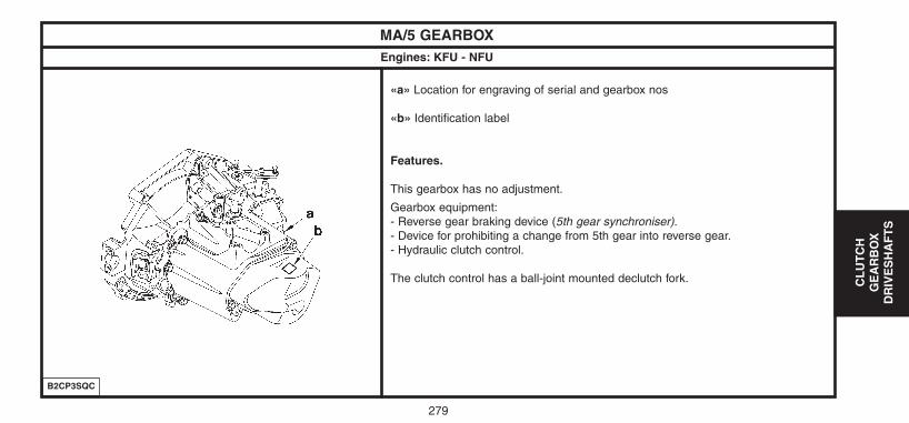
279
CL
UT
CH
GE
AR
BO
XD
RIV
ES
HA
FT
S
MA/5 GEARBOX Engines: KFU - NFU
«a» Location for engraving of serial and gearbox nos
«b» Identification label
Features.
This gearbox has no adjustment.
Gearbox equipment:- Reverse gear braking device (5th gear synchroniser).- Device for prohibiting a change from 5th gear into reverse gear.- Hydraulic clutch control.
The clutch control has a ball-joint mounted declutch fork.
B2CP3SQC
UK-C4-page271-321-2004 15/11/04 9:15 Page 279
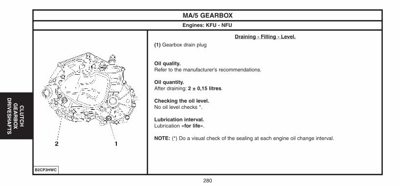
280
CL
UT
CH
GE
AR
BO
XD
RIV
ES
HA
FT
S
MA/5 GEARBOX Engines: KFU - NFU
Draining - Filling - Level.
(1) Gearbox drain plug
Oil quality.Refer to the manufacturer’s recommendations.
Oil quantity.After draining: 2 ± 0,15 litres.
Checking the oil level.No oil level checks *.
Lubrication interval.Lubrication «for life».
NOTE: (*) Do a visual check of the sealing at each engine oil change interval.
B2CP3HWC
UK-C4-page271-321-2004 15/11/04 9:15 Page 280
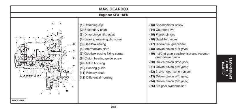
281
CL
UT
CH
GE
AR
BO
XD
RIV
ES
HA
FT
S
MA/5 GEARBOX Engines: KFU - NFU
(1) Retaining clip
(2) Secondary shaft
(3) Drive pinion (5th gear)
(4) Bearing retaining clip screw
(5) Gearbox casing
(6) Intermediate plate
(7) Gearbox casing fixing screw
(8) Clutch bearing guide screw
(9) Clutch housing
(10) Bearing guide
(11) Primary shaft
(12) Differential housing
(13) Speedometer screw
(14) Counter drive
(15) Planet pinions
(16) Satellite pinions
(17) Differential gearwheel
(18) Driven pinion (1st gear)
(19) 1st/2nd gear synchroniser and reverse gear driven pinion
(20) Driven pinion (2nd gear)
(21) Driven pinion (3rd gear)
(22) 3rd/4th gear synchroniser
(23) Driven pinion (4th gear)
(24) Driven pinion (5th gear)
(25) 5th gear synchroniser
B2CP3SRP
UK-C4-page271-321-2004 15/11/04 9:15 Page 281
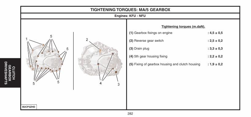
282
CL
UT
CH
GE
AR
BO
XD
RIV
ES
HA
FT
S
TIGHTENING TORQUES: MA/5 GEARBOX Engines: KFU - NFU
Tightening torques (m.daN).
(1) Gearbox fixings on engine : 4,5 ± 0,5
(2) Reverse gear switch : 2,5 ± 0,2
(3) Drain plug : 3,3 ± 0,3
(4) 5th gear housing fixing : 2,2 ± 0,2
(5) Fixing of gearbox housing and clutch housing : 1,9 ± 0,2
B2CP3ZHD
UK-C4-page271-321-2004 15/11/04 9:15 Page 282
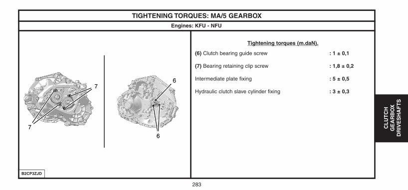
283
CL
UT
CH
GE
AR
BO
XD
RIV
ES
HA
FT
S
TIGHTENING TORQUES: MA/5 GEARBOX Engines: KFU - NFU
Tightening torques (m.daN).
(6) Clutch bearing guide screw : 1 ± 0,1
(7) Bearing retaining clip screw : 1,8 ± 0,2
Intermediate plate fixing : 5 ± 0,5
Hydraulic clutch slave cylinder fixing : 3 ± 0,3
B2CP3ZJD
UK-C4-page271-321-2004 15/11/04 9:15 Page 283
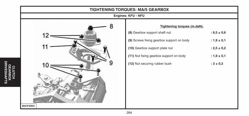
284
CL
UT
CH
GE
AR
BO
XD
RIV
ES
HA
FT
S
TIGHTENING TORQUES: MA/5 GEARBOX Engines: KFU - NFU
Tightening torques (m.daN).
(8) Gearbox support shaft nut : 6,5 ± 0,6
(9) Screws fixing gearbox support on body : 1,9 ± 0,1
(10) Gearbox support plate nut : 2,5 ± 0,2
(11) Nut fixing gearbox support on body : 1,9 ± 0,1
(12) Nut securing rubber bush : 3 ± 0,3
B2CP3ZKC
UK-C4-page271-321-2004 15/11/04 9:15 Page 284
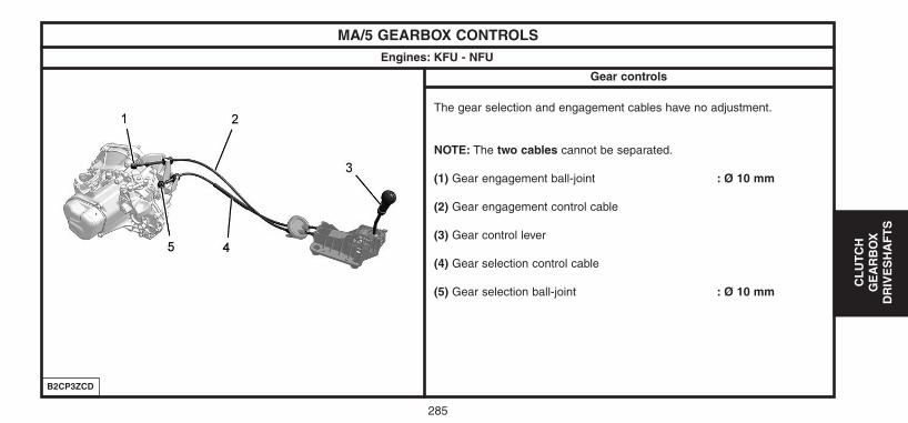
285
CL
UT
CH
GE
AR
BO
XD
RIV
ES
HA
FT
S
MA/5 GEARBOX CONTROLSEngines: KFU - NFU
The gear selection and engagement cables have no adjustment.
NOTE: The two cables cannot be separated.
(1) Gear engagement ball-joint : Ø 10 mm
(2) Gear engagement control cable
(3) Gear control lever
(4) Gear selection control cable
(5) Gear selection ball-joint : Ø 10 mm
B2CP3ZCD
Gear controls
UK-C4-page271-321-2004 15/11/04 9:15 Page 285
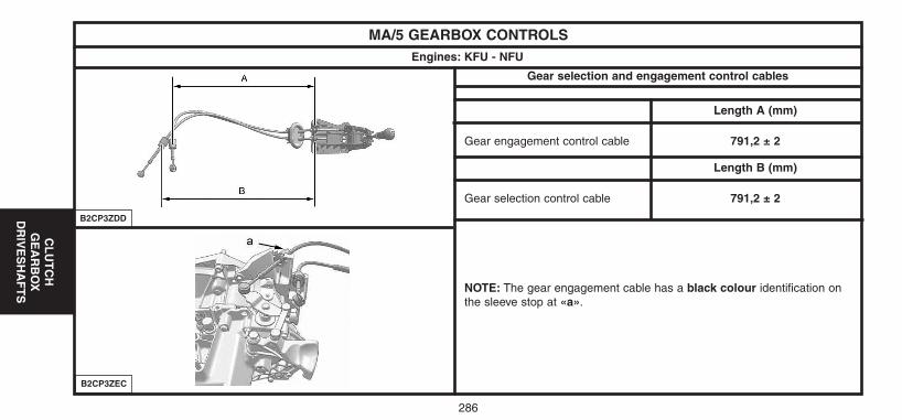
286
CL
UT
CH
GE
AR
BO
XD
RIV
ES
HA
FT
S
MA/5 GEARBOX CONTROLSEngines: KFU - NFU
Length A (mm)
Gear engagement control cable 791,2 ± 2
Length B (mm)
Gear selection control cable 791,2 ± 2
NOTE: The gear engagement cable has a black colour identification onthe sleeve stop at «a».
Gear selection and engagement control cables
B2CP3ZDD
B2CP3ZEC
UK-C4-page271-321-2004 15/11/04 9:15 Page 286
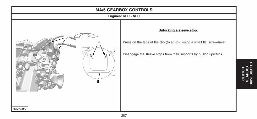
287
CL
UT
CH
GE
AR
BO
XD
RIV
ES
HA
FT
S
MA/5 GEARBOX CONTROLSEngines: KFU - NFU
Unlocking a sleeve stop.
Press on the tabs of the clip (6) at «b», using a small flat screwdriver.
Disengage the sleeve stops from their supports by pulling upwards.
B2CP3ZFD
UK-C4-page271-321-2004 15/11/04 9:15 Page 287
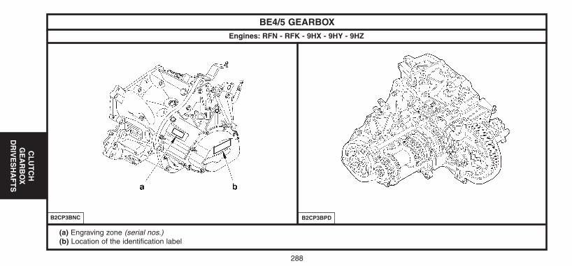
288
CL
UT
CH
GE
AR
BO
XD
RIV
ES
HA
FT
S
BE4/5 GEARBOX Engines: RFN - RFK - 9HX - 9HY - 9HZ
(a) Engraving zone (serial nos.)(b) Location of the identification label
B2CP3BNC B2CP3BPD
UK-C4-page271-321-2004 15/11/04 9:15 Page 288
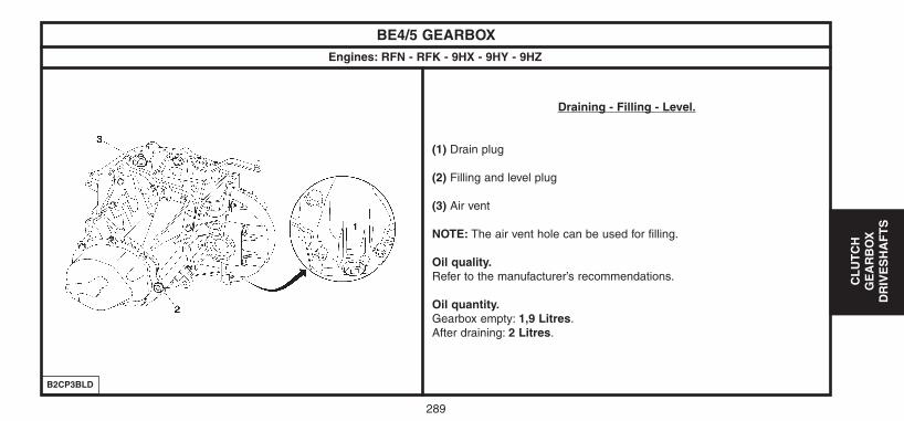
289
CL
UT
CH
GE
AR
BO
XD
RIV
ES
HA
FT
S
BE4/5 GEARBOX Engines: RFN - RFK - 9HX - 9HY - 9HZ
Draining - Filling - Level.
(1) Drain plug
(2) Filling and level plug
(3) Air vent
NOTE: The air vent hole can be used for filling.
Oil quality.Refer to the manufacturer’s recommendations.
Oil quantity.Gearbox empty: 1,9 Litres.After draining: 2 Litres.
B2CP3BLD
UK-C4-page271-321-2004 15/11/04 9:15 Page 289
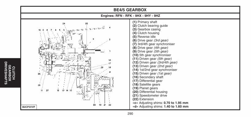
290
CL
UT
CH
GE
AR
BO
XD
RIV
ES
HA
FT
S
BE4/5 GEARBOX Engines: RFN - RFK - 9HX - 9HY - 9HZ
(1) Primary shaft(2) Clutch bearing guide(3) Gearbox casing(4) Clutch housing(5) Reverse idle(6) Drive gear (3rd gear)(7) 3rd/4th gear synchroniser(8) Drive gear (4th gear)(9) Drive gear (5th gear)(10) 5th gear synchroniser(11) Driven gear (5th gear)(12) Driven gear (3rd/4th gear)(13) Driven gear (2nd gear)(14) 1st/2nd gear synchroniser(15) Driven gear (1st gear)(16) Secondary shaft(17) Differential gear(18) Satellite gears(19) Planet gears(20) Differential housing(21) Speedometer drive(22) Extension«c» Adjusting shims: 0.70 to 1.95 mm«d» Adjusting shims: 1.40 to 1.60 mmB2CP3VVP
UK-C4-page271-321-2004 15/11/04 9:15 Page 290
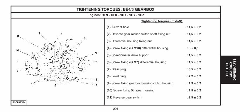
291
CL
UT
CH
GE
AR
BO
XD
RIV
ES
HA
FT
S
TIGHTENING TORQUES: BE4/5 GEARBOX Engines: RFN - RFK - 9HX - 9HY - 9HZ
Tightening torques (m.daN).
(1) Air vent hole : 1,5 ± 0,2
(2) Reverse gear rocker switch shaft fixing nut : 4,5 ± 0,2
(3) Differential housing fixing nut : 1,5 ± 0,2
(4) Screw fixing (Ø M10) differential housing : 5 ± 0,5
(5) Speedometer drive support : 1,5 ± 0,2
(6) Screw fixing (Ø M7) differential housing : 1,5 ± 0,2
(7) Drain plug : 3,5 ± 0,2
(8) Level plug : 2,2 ± 0,2
(9) Screw fixing gearbox housing/clutch housing : 1,3 ± 0,2
(10) Screw fixing 5th gear housing : 1,5 ± 0,2
(11) Reverse gear switch : 2,5 ± 0,2
B2CP3ZXD
UK-C4-page271-321-2004 15/11/04 9:15 Page 291
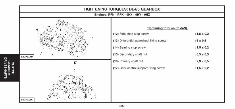
292
CL
UT
CH
GE
AR
BO
XD
RIV
ES
HA
FT
S
TIGHTENING TORQUES: BE4/5 GEARBOX Engines: RFN - RFK - 9HX - 9HY - 9HZ
Tightening torques (m.daN).
(12) Fork shaft stop screw : 1,5 ± 0,2
(13) Differential gearwheel fixing screw : 6 ± 0,5
(14) Bearing stop screw : 1,5 ± 0,2
(15) Secondary shaft nut : 6,5 ± 0,5
(16) Primary shaft nut : 7,3 ± 0,5
(17) Gear control support fixing screw : 1,5 ± 0,2
B2CP3ZZC
B2CP3ZYD
UK-C4-page271-321-2004 15/11/04 9:15 Page 292
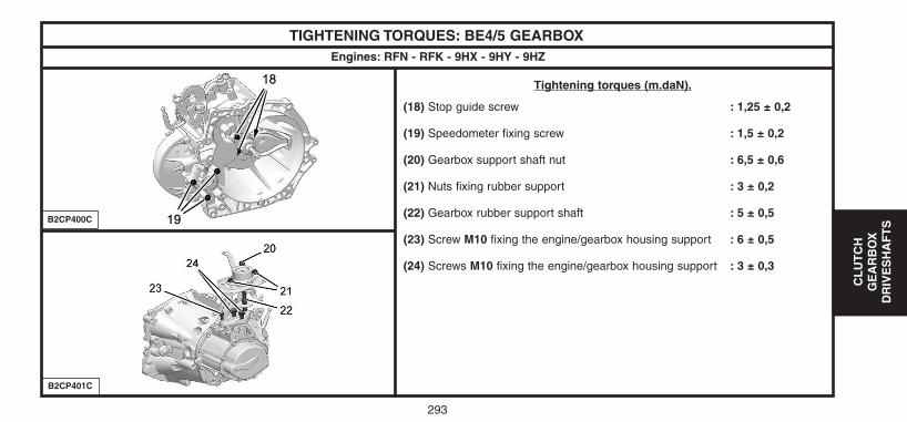
293
CL
UT
CH
GE
AR
BO
XD
RIV
ES
HA
FT
S
TIGHTENING TORQUES: BE4/5 GEARBOX Engines: RFN - RFK - 9HX - 9HY - 9HZ
Tightening torques (m.daN).
(18) Stop guide screw : 1,25 ± 0,2
(19) Speedometer fixing screw : 1,5 ± 0,2
(20) Gearbox support shaft nut : 6,5 ± 0,6
(21) Nuts fixing rubber support : 3 ± 0,2
(22) Gearbox rubber support shaft : 5 ± 0,5
(23) Screw M10 fixing the engine/gearbox housing support : 6 ± 0,5
(24) Screws M10 fixing the engine/gearbox housing support : 3 ± 0,3
B2CP401C
B2CP400C
UK-C4-page271-321-2004 15/11/04 9:15 Page 293
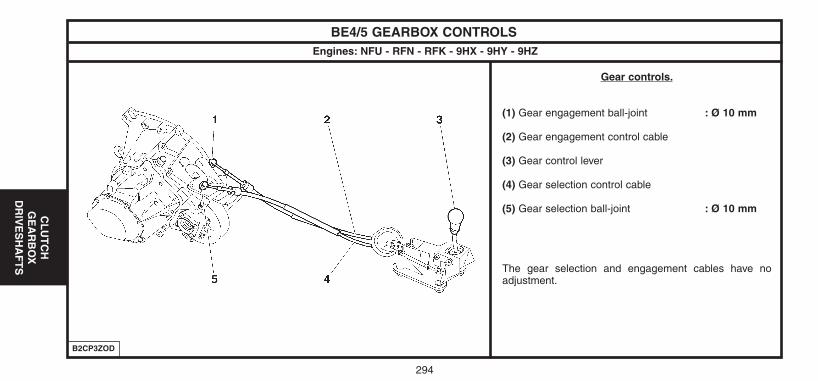
294
CL
UT
CH
GE
AR
BO
XD
RIV
ES
HA
FT
S
BE4/5 GEARBOX CONTROLSEngines: NFU - RFN - RFK - 9HX - 9HY - 9HZ
Gear controls.
(1) Gear engagement ball-joint : Ø 10 mm
(2) Gear engagement control cable
(3) Gear control lever
(4) Gear selection control cable
(5) Gear selection ball-joint : Ø 10 mm
The gear selection and engagement cables have noadjustment.
B2CP3ZOD
UK-C4-page271-321-2004 15/11/04 9:15 Page 294
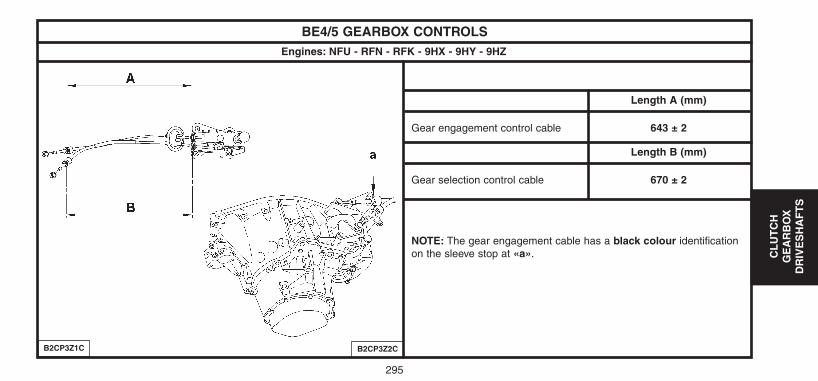
295
CL
UT
CH
GE
AR
BO
XD
RIV
ES
HA
FT
S
BE4/5 GEARBOX CONTROLSEngines: NFU - RFN - RFK - 9HX - 9HY - 9HZ
Length A (mm)
Gear engagement control cable 643 ± 2
Length B (mm)
Gear selection control cable 670 ± 2
NOTE: The gear engagement cable has a black colour identificationon the sleeve stop at «a».
B2CP3Z1C B2CP3Z2C
UK-C4-page271-321-2004 15/11/04 9:15 Page 295
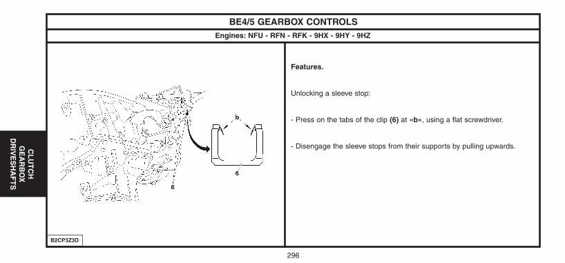
296
CL
UT
CH
GE
AR
BO
XD
RIV
ES
HA
FT
S
BE4/5 GEARBOX CONTROLSEngines: NFU - RFN - RFK - 9HX - 9HY - 9HZ
Features.
Unlocking a sleeve stop:
- Press on the tabs of the clip (6) at «b», using a flat screwdriver.
- Disengage the sleeve stops from their supports by pulling upwards.
B2CP3Z3D
UK-C4-page271-321-2004 15/11/04 9:15 Page 296
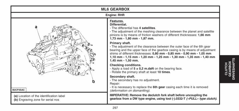
297
CL
UT
CH
GE
AR
BO
XD
RIV
ES
HA
FT
S
ML6 GEARBOX Engine: RHR
Features.Differential.- The differential has 4 satellites.- The adjustment of the meshing clearance between the planet and satellitepinions is by means of friction washers of different thicknesses: 1,66 mm 1,73 mm - 1,80 mm - 1,87 mm.Primary shaft.- The adjustment of the clearance between the outer face of the 6th gearbearing and the upper face of the gearbox casing is by means of adjustmentshims of different thicknesses: 0,80 mm - 0,85 mm - 0,90 mm - 1,05 mm1,10 mm - 1,15 mm - 1,20 mm - 1,25 mm - 1,30 mm - 1,35 mm - 1,40 mm1,45 mm - 1,50 mm.Checking conditions.- Apply a load of 5 ± 0,2 m.daN on the bearing face.- Rotate the primary shaft at least 10 times.
Secondary shaft.- The secondary has no adjustment.Repair:- It is necessary to replace the 6th gear casing each time it is removed(deformation on dismantling).
IMPERATIVE: Remove the declutch fork shaft before uncoupling thegearbox from a DW type engine, using tool (-).0332-T («PULL» type clutch).
B2CP3SAC
(a) Location of the identification label(b) Engraving zone for serial nos
UK-C4-page271-321-2004 15/11/04 9:15 Page 297
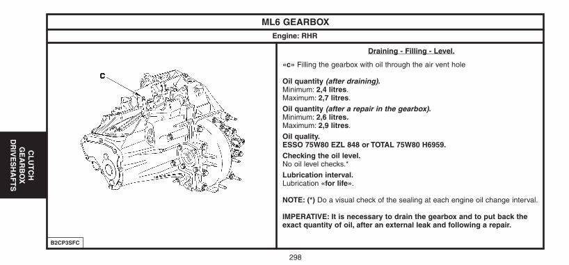
298
CL
UT
CH
GE
AR
BO
XD
RIV
ES
HA
FT
S
ML6 GEARBOX Engine: RHR
Draining - Filling - Level.
«c» Filling the gearbox with oil through the air vent hole
Oil quantity (after draining).Minimum: 2,4 litres.Maximum: 2,7 litres.
Oil quantity (after a repair in the gearbox).Minimum: 2,6 litres.Maximum: 2,9 litres.
Oil quality.ESSO 75W80 EZL 848 or TOTAL 75W80 H6959.Checking the oil level.No oil level checks.*
Lubrication interval.Lubrication «for life».
NOTE: (*) Do a visual check of the sealing at each engine oil change interval.
IMPERATIVE: It is necessary to drain the gearbox and to put back theexact quantity of oil, after an external leak and following a repair.
B2CP3SFC
UK-C4-page271-321-2004 15/11/04 9:15 Page 298
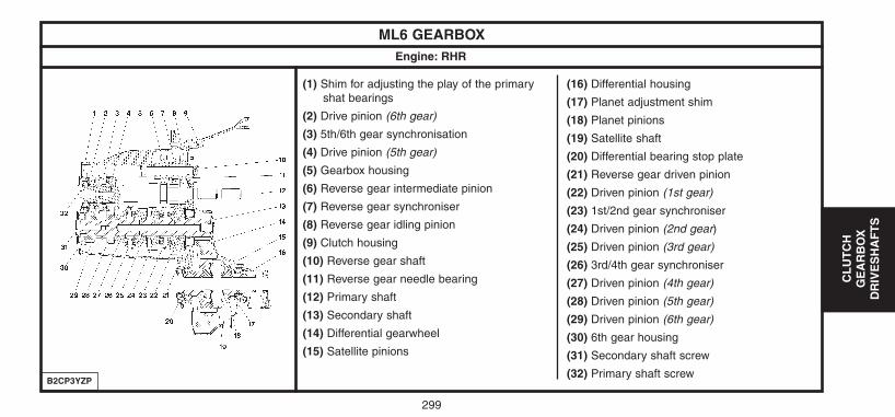
299
CL
UT
CH
GE
AR
BO
XD
RIV
ES
HA
FT
S
ML6 GEARBOX Engine: RHR
(1) Shim for adjusting the play of the primary shat bearings
(2) Drive pinion (6th gear)
(3) 5th/6th gear synchronisation
(4) Drive pinion (5th gear)
(5) Gearbox housing
(6) Reverse gear intermediate pinion
(7) Reverse gear synchroniser
(8) Reverse gear idling pinion
(9) Clutch housing
(10) Reverse gear shaft
(11) Reverse gear needle bearing
(12) Primary shaft
(13) Secondary shaft
(14) Differential gearwheel
(15) Satellite pinions
(16) Differential housing
(17) Planet adjustment shim
(18) Planet pinions
(19) Satellite shaft
(20) Differential bearing stop plate
(21) Reverse gear driven pinion
(22) Driven pinion (1st gear)
(23) 1st/2nd gear synchroniser
(24) Driven pinion (2nd gear)
(25) Driven pinion (3rd gear)
(26) 3rd/4th gear synchroniser
(27) Driven pinion (4th gear)
(28) Driven pinion (5th gear)
(29) Driven pinion (6th gear)
(30) 6th gear housing
(31) Secondary shaft screw
(32) Primary shaft screwB2CP3YZP
UK-C4-page271-321-2004 15/11/04 9:15 Page 299
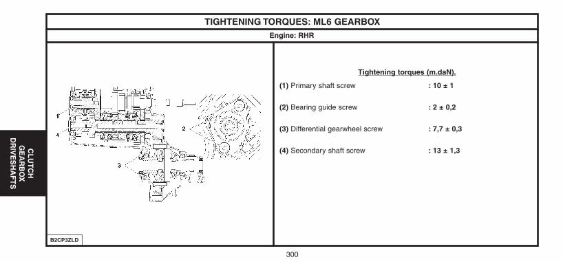
300
CL
UT
CH
GE
AR
BO
XD
RIV
ES
HA
FT
S
TIGHTENING TORQUES: ML6 GEARBOX Engine: RHR
Tightening torques (m.daN).
(1) Primary shaft screw : 10 ± 1
(2) Bearing guide screw : 2 ± 0,2
(3) Differential gearwheel screw : 7,7 ± 0,3
(4) Secondary shaft screw : 13 ± 1,3
B2CP3ZLD
UK-C4-page271-321-2004 15/11/04 9:15 Page 300

301
CL
UT
CH
GE
AR
BO
XD
RIV
ES
HA
FT
S
TIGHTENING TORQUES: ML6 GEARBOX Engine: RHR
Tightening torques (m.daN).
(5) Reverse gear switch : 2,5 ± 0,5
(6) Level plug : 3 ± 0,2
(7) Drain plug : 3 ± 0,3
(8) Differential bearing stop plate screw : 3 ± 0,3
(9) Screw fixing gearbox housing/clutch housing : 3 ± 0,3
(10) 6th gear housing fixing screw : 2 ± 0,2
(11) Differential housing fixing (screws M8) : 1,8 ± 0,3
(12) Differential housing fixing (screws M10) : 4 ± 0,8
B2CP3ZMP
UK-C4-page271-321-2004 15/11/04 9:15 Page 301
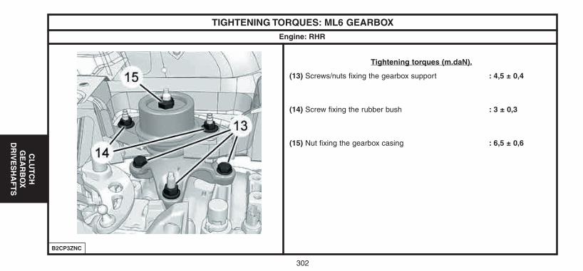
302
CL
UT
CH
GE
AR
BO
XD
RIV
ES
HA
FT
S
TIGHTENING TORQUES: ML6 GEARBOX Engine: RHR
B2CP3ZNC
Tightening torques (m.daN).
(13) Screws/nuts fixing the gearbox support : 4,5 ± 0,4
(14) Screw fixing the rubber bush : 3 ± 0,3
(15) Nut fixing the gearbox casing : 6,5 ± 0,6
UK-C4-page271-321-2004 15/11/04 9:15 Page 302
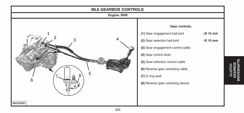
303
CL
UT
CH
GE
AR
BO
XD
RIV
ES
HA
FT
S
ML6 GEARBOX CONTROLSEngine: RHR
Gear controls.
(1) Gear engagement ball-joint : Ø 10 mm
(2) Gear selection ball-joint : Ø 10 mm
(3) Gear engagement control cable
(4) Gear control lever
(5) Gear selection control cable
(6) Reverse gear unlocking cable
(7) O-ring seal
(8) Reverse gear unlocking device
B2CP3ZPD
UK-C4-page271-321-2004 15/11/04 9:15 Page 303
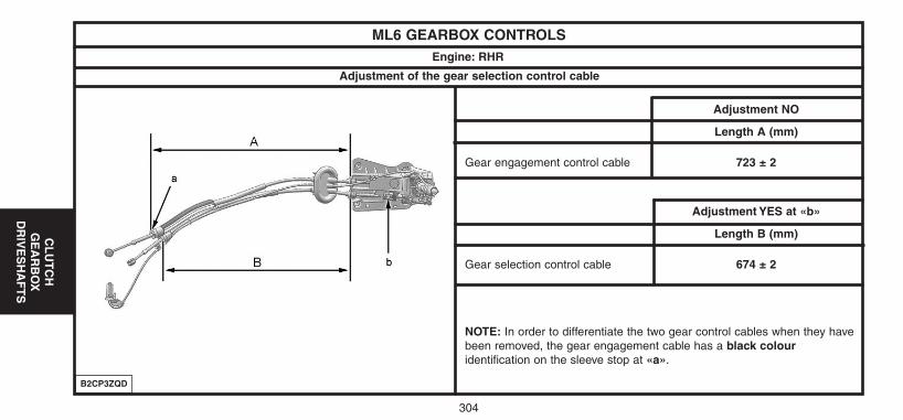
304
CL
UT
CH
GE
AR
BO
XD
RIV
ES
HA
FT
S
ML6 GEARBOX CONTROLSEngine: RHR
B2CP3ZQD
Adjustment NO
Length A (mm)
Gear engagement control cable 723 ± 2
Adjustment YES at «b»
Length B (mm)
Gear selection control cable 674 ± 2
NOTE: In order to differentiate the two gear control cables when they havebeen removed, the gear engagement cable has a black colouridentification on the sleeve stop at «a».
Adjustment of the gear selection control cable
UK-C4-page271-321-2004 15/11/04 9:15 Page 304
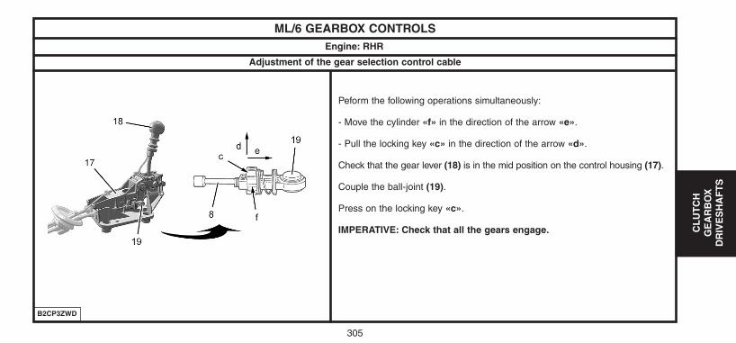
305
CL
UT
CH
GE
AR
BO
XD
RIV
ES
HA
FT
S
ML/6 GEARBOX CONTROLSEngine: RHR
Peform the following operations simultaneously:
- Move the cylinder «f» in the direction of the arrow «e».
- Pull the locking key «c» in the direction of the arrow «d».
Check that the gear lever (18) is in the mid position on the control housing (17).
Couple the ball-joint (19).
Press on the locking key «c».
IMPERATIVE: Check that all the gears engage.
B2CP3ZWD
Adjustment of the gear selection control cable
UK-C4-page271-321-2004 15/11/04 9:15 Page 305
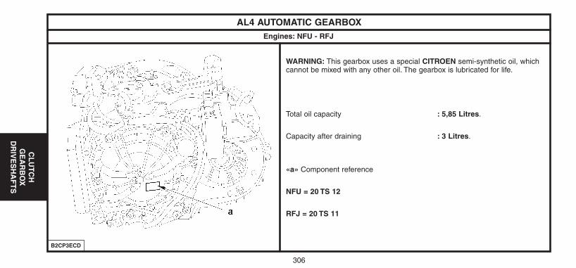
306
CL
UT
CH
GE
AR
BO
XD
RIV
ES
HA
FT
S
AL4 AUTOMATIC GEARBOX Engines: NFU - RFJ
B2CP3ECD
WARNING: This gearbox uses a special CITROEN semi-synthetic oil, whichcannot be mixed with any other oil. The gearbox is lubricated for life.
Total oil capacity : 5,85 Litres.
Capacity after draining : 3 Litres.
«a» Component reference
NFU = 20 TS 12
RFJ = 20 TS 11
UK-C4-page271-321-2004 15/11/04 9:15 Page 306
307
CL
UT
CH
GE
AR
BO
XD
RIV
ES
HA
FT
S
RECOMMENDATIONS - PRECAUTIONS (AL4 AUTOMATIC GEARBOX)Engines: NFU - RFJ
Towing.The front of the vehicle must be raised in order to be towed.If the front of the vehicle cannot be raised.
IMPERATIVE: Put gear lever in position «N».- Do not add any oil.- Do not exceed 30 mph over a distance of 30 miles of maximum.
Driving.Never drive with the ignition switched off.Never push the vehicle to try to start it (impossible with an automaticgearbox).
Lubrication.The automatic gearbox is only lubricated when the engine is running.
Removing - Refitting (automatic gearbox).
WARNING: Never place the gearbox on its lower casing(risk of deformation of the tray and damage to the hydraulic block).- Do not use the connectors as handles to lift,
turn, hold or push the gearbox.
IMPERATIVE:- Set the converter retaining peg when the gearbox is being removed.- Place the centring peg to line up the gearbox on the engine
(remove the converter retaining peg just prior to this lining up).
WARNING: In emergency mode, there is a noticeable snatching whenchanging «P» � «R» or «N» � «R».
PRECAUTIONS TO BE TAKEN
UK-C4-page271-321-2004 15/11/04 9:15 Page 307
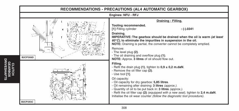
308
CL
UT
CH
GE
AR
BO
XD
RIV
ES
HA
FT
S
RECOMMENDATIONS - PRECAUTIONS (AL4 AUTOMATIC GEARBOX)Engines: NFU - RFJ
B2CP3X6D
B2CP3X5C
Draining - Filling.Tooling recommended.[1] Filling cylinder : (-).0341Draining.IMPERATIVE: The gearbox should be drained when the oil is warm (at least60°C), to eliminate the impurities in suspension in the oil.NOTE: Draining is partial, the converter cannot be completely emptied.
Remove:- The level plug (2).- The oil draining and overflow plug (1).NOTE: Approx. 3 litres of oil should flow out.
Filling.- Refit the drain plug (1), tighten to 0,9 ± 0,2 m.daN.- Remove the oil filler cap (2).- Use tool [1].Oil capacity:- Oil capacity for dry gearbox: 5,85 litres.- Oil remaining after draining: 3 litres (approx.).- Quantity of oil to be put back in: 3 litres (approx.).- Refit the oil filler cap (2) (equipped with a new seal), tighten to 2,4 m.daN.Initialise the oil wear counter (follow the diagnostic tool procedure).
UK-C4-page271-321-2004 15/11/04 9:15 Page 308
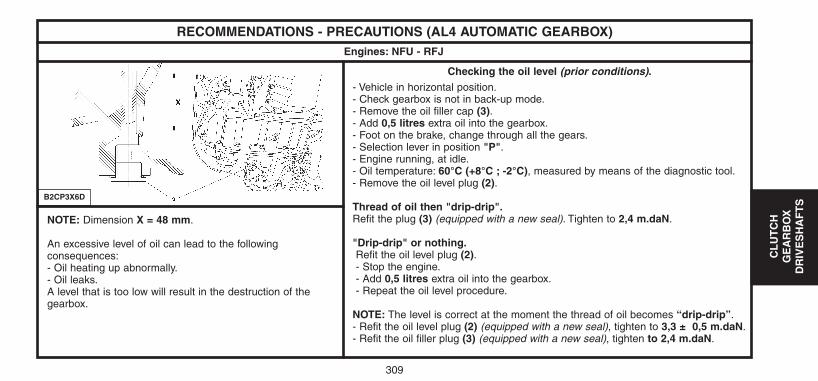
309
CL
UT
CH
GE
AR
BO
XD
RIV
ES
HA
FT
S
RECOMMENDATIONS - PRECAUTIONS (AL4 AUTOMATIC GEARBOX)Engines: NFU - RFJ
B2CP3X6D
Checking the oil level (prior conditions).- Vehicle in horizontal position.- Check gearbox is not in back-up mode.- Remove the oil filler cap (3).- Add 0,5 litres extra oil into the gearbox.- Foot on the brake, change through all the gears.- Selection lever in position "P".- Engine running, at idle.- Oil temperature: 60°C (+8°C ; -2°C), measured by means of the diagnostic tool.- Remove the oil level plug (2).
Thread of oil then "drip-drip".Refit the plug (3) (equipped with a new seal). Tighten to 2,4 m.daN.
"Drip-drip" or nothing.Refit the oil level plug (2).- Stop the engine.- Add 0,5 litres extra oil into the gearbox.- Repeat the oil level procedure.
NOTE: The level is correct at the moment the thread of oil becomes “drip-drip”.- Refit the oil level plug (2) (equipped with a new seal), tighten to 3,3 ± 0,5 m.daN.- Refit the oil filler plug (3) (equipped with a new seal), tighten to 2,4 m.daN.
NOTE: Dimension X = 48 mm.
An excessive level of oil can lead to the followingconsequences:- Oil heating up abnormally.- Oil leaks.A level that is too low will result in the destruction of thegearbox.
UK-C4-page271-321-2004 15/11/04 9:15 Page 309
310
CL
UT
CH
GE
AR
BO
XD
RIV
ES
HA
FT
S
RECOMMENDATIONS - PRECAUTIONS (AL4 AUTOMATIC GEARBOX)Engines: NFU - RFJ
When the ECU detects a value that is incorrect or absent on oneof its inputs or outputs:
- It writes the fault into memory.- For each type of associated context, it records the context of the
earliest fault into memory.- It launches a back-up mode strategy.
There are two sort of back-up mode:
- The ECU uses replacement values (impact on comfort, gear changingquality, loss of functions).
- Change to emergency mode (only 3rd gear and reverse gear areavailable).
Reading of fault codes.
Carry out a reading of the fault codes.- Absence of fault codes.Carry out a measuring of parameters.
Presence of faults confirmed:
- YES: Perform the necessary repairs.- NO: Read the fault codes: engine ECU.
Carry out a road test.
Having carried out an ECU initialisation procedure, for a certain timeone may obtain gear changing quality that is more or less good(adaptation of the ECU parameters to the gearbox).To improve the quality, it is necessary to perform a road test withfrequent changing through the gears (auto-adaptive laws).
PROCEDURE BEFORE A REPAIR
UK-C4-page271-321-2004 15/11/04 9:15 Page 310
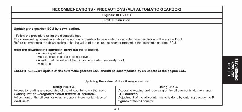
311
CL
UT
CH
GE
AR
BO
XD
RIV
ES
HA
FT
S
RECOMMENDATIONS - PRECAUTIONS (AL4 AUTOMATIC GEARBOX)Engines: NFU - RFJ
ECU: Initialisation
Updating the gearbox ECU by downloading.
- Follow the procedure using the diagnostic tool.The downloading operation enables the automatic gearbox to be updated, or adapted to an evolution of the engine ECU.Before commencing the downloading, take the value of the oil usage counter present in the automatic gearbox ECU.
After the downloading operation, carry out the following.- A clearing of faults.- An initialisation of the auto-adaptives.- A writing of the value of the oil usage counter previously read.- A road test.
ESSENTIAL: Every update of the automatic gearbox ECU should be accompanied by an update of the engine ECU.
Updating the value of the oil usage counter.
Using PROXIAAccess to reading and recording of the oil counter is via the menu:«Configuration (integrated circuit button)/Oil counter».Adjustment of the oil counter value is done in incremental steps of2750 units.
Using LEXIAAccess to reading and recording of the oil counter is via the menu:«Oil counter».Adjustment of the oil counter value is done by entering directly the 5figures of the oil counter.
UK-C4-page271-321-2004 15/11/04 9:15 Page 311
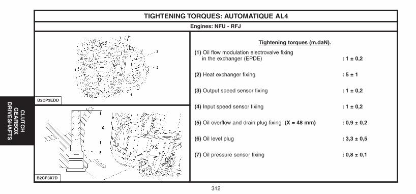
312
CL
UT
CH
GE
AR
BO
XD
RIV
ES
HA
FT
S
TIGHTENING TORQUES: AUTOMATIQUE AL4Engines: NFU - RFJ
B2CP3EDD
B2CP3X7D
Tightening torques (m.daN).
(1) Oil flow modulation electrovalve fixingin the exchanger (EPDE) : 1 ± 0,2
(2) Heat exchanger fixing : 5 ± 1
(3) Output speed sensor fixing : 1 ± 0,2
(4) Input speed sensor fixing : 1 ± 0,2
(5) Oil overflow and drain plug fixing (X = 48 mm) : 0,9 ± 0,2
(6) Oil level plug : 3,3 ± 0,5
(7) Oil pressure sensor fixing : 0,8 ± 0,1
UK-C4-page271-321-2004 15/11/04 9:15 Page 312
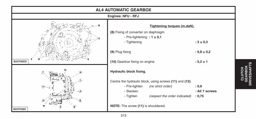
313
CL
UT
CH
GE
AR
BO
XD
RIV
ES
HA
FT
S
AL4 AUTOMATIC GEARBOXEngines: NFU - RFJ
B2CP3EED
B2CP3X8C
Tightening torques (m.daN).
(8) Fixing of converter on diaphragm
- Pre-tightening : 1 ± 0,1- Tightening : 3 ± 0,3
(9) Plug fixing : 0,8 ± 0,2
(10) Gearbox fixing on engine : 5,2 ± 1
Hydraulic block fixing.
Centre the hydraulic block, using screws (11) and (12).- Pre-tighten (no strict order) : 0,9 - Slacken : All 7 screws - Tighten (respect the order indicated) : 0,75
NOTE: The screw (11) is shouldered.
UK-C4-page271-321-2004 15/11/04 9:15 Page 313
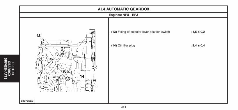
314
CL
UT
CH
GE
AR
BO
XD
RIV
ES
HA
FT
S
AL4 AUTOMATIC GEARBOXEngines: NFU - RFJ
B2CP3EGC
(13) Fixing of selector lever position switch : 1,5 ± 0,2
(14) Oil filler plug : 2,4 ± 0,4
UK-C4-page271-321-2004 15/11/04 9:15 Page 314
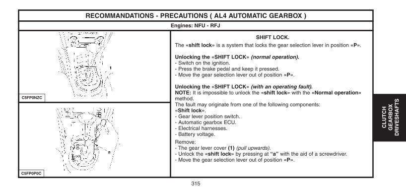
315
CL
UT
CH
GE
AR
BO
XD
RIV
ES
HA
FT
S
RECOMMANDATIONS - PRECAUTIONS ( AL4 AUTOMATIC GEARBOX )Engines: NFU - RFJ
C5FP0NZC
C5FP0P0C
SHIFT LOCK.The «shift lock» is a system that locks the gear selection lever in position «P».
Unlocking the «SHIFT LOCK» (normal operation).- Switch on the ignition.- Press the brake pedal and keep it pressed.- Move the gear selection lever out of position «P».
Unlocking the «SHIFT LOCK» (with an operating fault).NOTE: It is impossible to unlock the «shift lock» with the «Normal operation»method.The fault may originate from one of the following components:«Shift lock».- Gear lever position switch.- Automatic gearbox ECU.- Electrical harnesses.- Battery voltage.
Remove:- The gear lever cover (1) (pull upwards).- Unlock the «shift lock» by pressing at “a” with the aid of a screwdriver.- Move the gear selection lever out of position «P».
UK-C4-page271-321-2004 15/11/04 9:15 Page 315
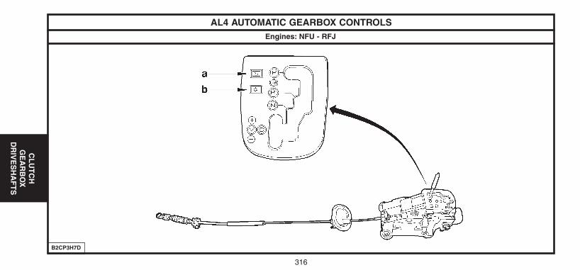
316
CL
UT
CH
GE
AR
BO
XD
RIV
ES
HA
FT
S
AL4 AUTOMATIC GEARBOX CONTROLSEngines: NFU - RFJ
B2CP3H7D
UK-C4-page271-321-2004 15/11/04 9:15 Page 316

317
CL
UT
CH
GE
AR
BO
XD
RIV
ES
HA
FT
S
AL4 AUTOMATIC GEARBOX CONTROLSEngines: NFU - RFJ
The gear selection lever is guided by the shape of the step grille and by a recall spring which holds it to the left.
The gear control has 5 positions:- «P» Parking (locking and immobilisation of the vehicle).w- «R» Revrse gear.- «N» Neutral.- «D» Drive (use of the four forward gears in automatic and auto-adaptive operation).- «M» Manual (this position allows the driver to choose his gears sequentially by pulling «M» or pushing «M+» on the gear selection lever).
NOTE: Only positions «P» or «N» authorise starting of the engine.In position «M», the selection is by means of an electronic sensor situated close to the selection lever.The variation of flux necessary to affect the sensor cells is obtained by a magnet on the lever opposite the cells, provoking the changes of status.The information on this is transmitted to the gearbox ECU.
NOTE: On a vehicle equipped with «shift lock», it is necessary to switch on the ignition and press the brake pedal to release the selection leverfrom position «P».
The two switches positioned on the gear control grille allow the driver to choose one of the following three driving programmes:- Normal programme. The Normal programme operates in the absence of any other selection being made (auto-adaptive mode ; eco law).- «a» Sport programme. The Sport programme permits a more dynamic driving style, with greater performances and acceleration.- «b» Snow programme. The Snow programme facilitates moving off and traction on ground that has limited adhesion.To revert to the Normal programme, you have to press a second time on the sport or snow switch.
UK-C4-page271-321-2004 15/11/04 9:15 Page 317
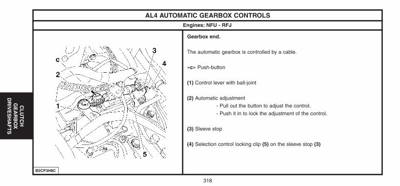
318
CL
UT
CH
GE
AR
BO
XD
RIV
ES
HA
FT
S
AL4 AUTOMATIC GEARBOX CONTROLSEngines: NFU - RFJ
B2CP3H8C
Gearbox end.
The automatic gearbox is controlled by a cable.
«c» Push-button
(1) Control lever with ball-joint
(2) Automatic adjustment
- Pull out the button to adjust the control.
- Push it in to lock the adjustment of the control.
(3) Sleeve stop
(4) Selection control locking clip (5) on the sleeve stop (3)
UK-C4-page271-321-2004 15/11/04 9:15 Page 318
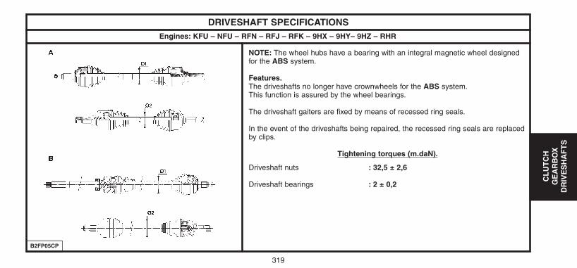
319
CL
UT
CH
GE
AR
BO
XD
RIV
ES
HA
FT
S
DRIVESHAFT SPECIFICATIONSEngines: KFU – NFU – RFN – RFJ – RFK – 9HX – 9HY– 9HZ – RHR
B2FP05CP
NOTE: The wheel hubs have a bearing with an integral magnetic wheel designedfor the ABS system.
Features.The driveshafts no longer have crownwheels for the ABS system.This function is assured by the wheel bearings.
The driveshaft gaiters are fixed by means of recessed ring seals.
In the event of the driveshafts being repaired, the recessed ring seals are replacedby clips.
Tightening torques (m.daN).
Driveshaft nuts : 32,5 ± 2,6
Driveshaft bearings : 2 ± 0,2
UK-C4-page271-321-2004 15/11/04 9:15 Page 319
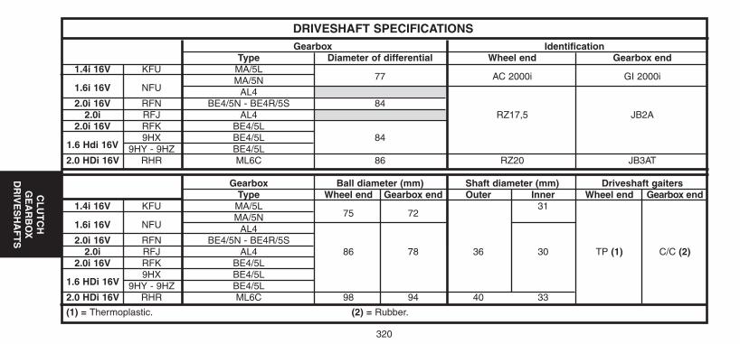
320
CL
UT
CH
GE
AR
BO
XD
RIV
ES
HA
FT
S
DRIVESHAFT SPECIFICATIONSGearbox Identification
Type Diameter of differential Wheel end Gearbox end1.4i 16V KFU MA/5L
77 AC 2000i GI 2000i1.6i 16V NFU
MA/5NAL4
2.0i 16V RFN BE4/5N - BE4R/5S 842.0i RFJ AL4 RZ17,5 JB2A
2.0i 16V RFK BE4/5L
1.6 Hdi 16V 9HX BE4/5L 84
9HY - 9HZ BE4/5L2.0 HDi 16V RHR ML6C 86 RZ20 JB3AT
Gearbox Ball diameter (mm) Shaft diameter (mm) Driveshaft gaitersType Wheel end Gearbox end Outer Inner Wheel end Gearbox end
1.4i 16V KFU MA/5L75 72
31
1.6i 16V NFUMA/5N
AL42.0i 16V RFN BE4/5N - BE4R/5S
2.0i RFJ AL4 86 78 36 30 TP (1) C/C (2)2.0i 16V RFK BE4/5L
1.6 HDi 16V9HX BE4/5L
9HY - 9HZ BE4/5L2.0 HDi 16V RHR ML6C 98 94 40 33
(1) = Thermoplastic. (2) = Rubber.
UK-C4-page271-321-2004 15/11/04 9:15 Page 320
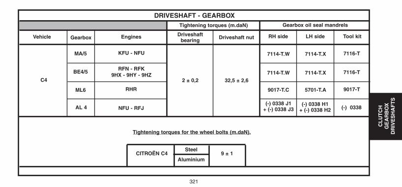
321
CL
UT
CH
GE
AR
BO
XD
RIV
ES
HA
FT
S
DRIVESHAFT - GEARBOXTightening torques (m.daN)
Driveshaftbearing
EnginesVehicle Gearbox RH side LH side Tool kit
Gearbox oil seal mandrels
32,5 ± 2,6
7114-T.W
Tightening torques for the wheel bolts (m.daN).
(-) 0338 J1+ (-) 0338 J3
(-) 0338 H1+ (-) 0338 H2 (-) 0338
7114-T.X 7116-T
Driveshaft nut
KFU - NFU
RFN - RFK9HX - 9HY - 9HZ
MA/5
C4 2 ± 0,2
BE4/5
ML6
AL 4
RHR
NFU - RFJ
7114-T.W 7114-T.X 7116-T
9017-T.C 5701-T.A 9017-T
CITROËN C4Steel
9 ± 1Aluminium
UK-C4-page271-321-2004 15/11/04 9:15 Page 321
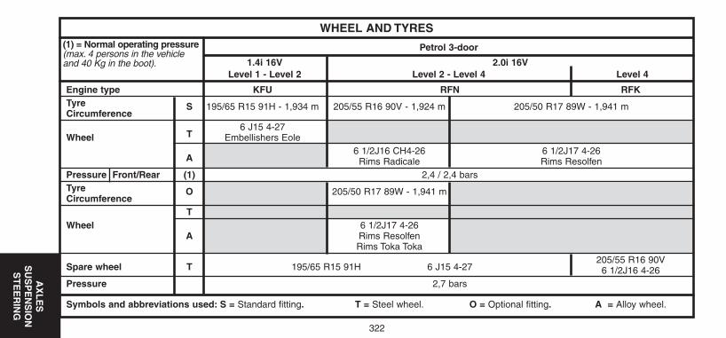
WHEEL AND TYRES
Engine type KFU RFN RFKTyreCircumference
S 195/65 R15 91H - 1,934 m 205/55 R16 90V - 1,924 m 205/50 R17 89W - 1,941 m
T6 J15 4-27
Wheel Embellishers Eole
A6 1/2J16 CH4-26 6 1/2J17 4-26
Rims Radicale Rims ResolfenPressure Front/Rear (1) 2,4 / 2,4 barsTyreCircumference
O 205/50 R17 89W - 1,941 m
TWheel 6 1/2J17 4-26
A Rims ResolfenRims Toka Toka
Spare wheel T 195/65 R15 91H 6 J15 4-27205/55 R16 90V6 1/2J16 4-26
Pressure 2,7 bars
Symbols and abbreviations used: S = Standard fitting. T = Steel wheel. O = Optional fitting. A = Alloy wheel.
(1) = Normal operating pressure(max. 4 persons in the vehicleand 40 Kg in the boot).
Petrol 3-door
1.4i 16V 2.0i 16VLevel 1 - Level 2 Level 2 - Level 4 Level 4
322
AX
LE
S
SU
SP
EN
SIO
NS
TE
ER
ING
UK-C4-page322-360-2004 15/11/04 9:07 Page 322
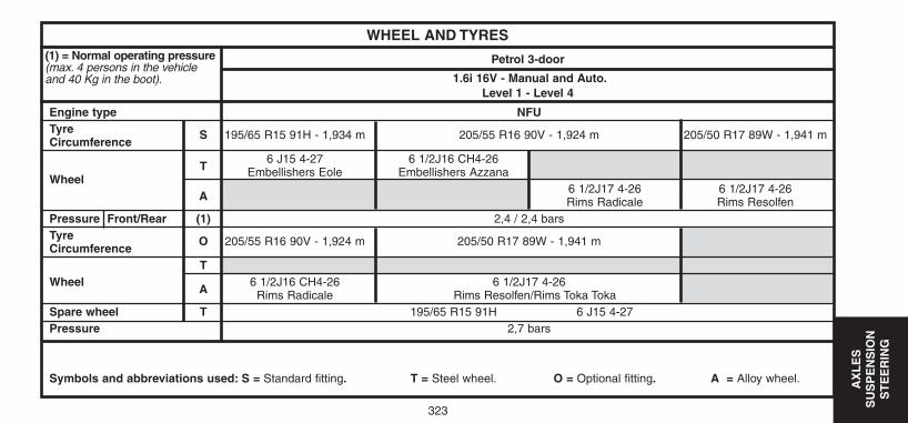
AX
LE
S
SU
SP
EN
SIO
NS
TE
ER
ING
323
WHEEL AND TYRES
Engine type NFUTyreCircumference
S 195/65 R15 91H - 1,934 m 205/55 R16 90V - 1,924 m 205/50 R17 89W - 1,941 m
T6 J15 4-27 6 1/2J16 CH4-26
WheelEmbellishers Eole Embellishers Azzana
A6 1/2J17 4-26 6 1/2J17 4-26Rims Radicale Rims Resolfen
Pressure Front/Rear (1) 2,4 / 2,4 barsTyre Circumference
O 205/55 R16 90V - 1,924 m 205/50 R17 89W - 1,941 m
TWheel
A6 1/2J16 CH4-26 6 1/2J17 4-26
Rims Radicale Rims Resolfen/Rims Toka TokaSpare wheel T 195/65 R15 91H 6 J15 4-27Pressure 2,7 bars
Symbols and abbreviations used: S = Standard fitting. T = Steel wheel. O = Optional fitting. A = Alloy wheel.
(1) = Normal operating pressure(max. 4 persons in the vehicleand 40 Kg in the boot).
Petrol 3-door
1.6i 16V - Manual and Auto.Level 1 - Level 4
UK-C4-page322-360-2004 15/11/04 9:07 Page 323
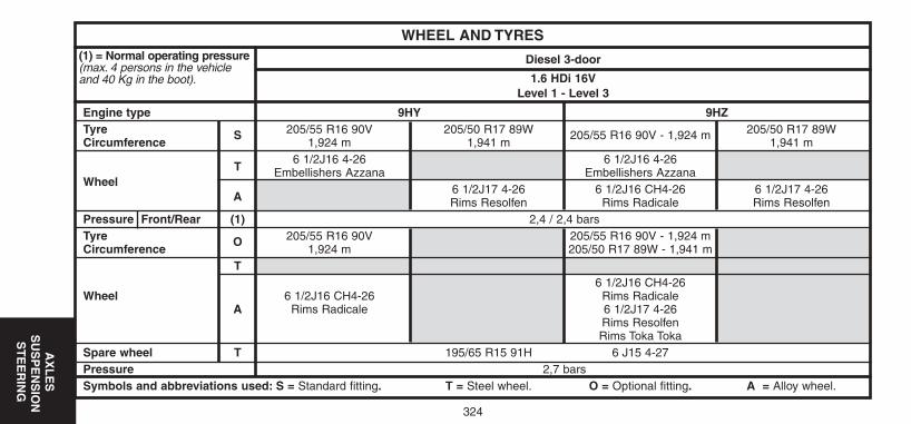
AX
LE
SS
US
PE
NS
ION
ST
EE
RIN
G
324
WHEEL AND TYRES
Engine type 9HY 9HZTyre 205/55 R16 90V 205/50 R17 89W 205/50 R17 89WCircumference
S1,924 m 1,941 m
205/55 R16 90V - 1,924 m1,941 m
T6 1/2J16 4-26 6 1/2J16 4-26
Embellishers Azzana Embellishers AzzanaWheel
A6 1/2J17 4-26 6 1/2J16 CH4-26 6 1/2J17 4-26Rims Resolfen Rims Radicale Rims Resolfen
Pressure Front/Rear (1) 2,4 / 2,4 barsTyre 205/55 R16 90V 205/55 R16 90V - 1,924 mCircumference
O1,924 m 205/50 R17 89W - 1,941 m
T6 1/2J16 CH4-26
Wheel 6 1/2J16 CH4-26 Rims RadicaleA Rims Radicale 6 1/2J17 4-26
Rims ResolfenRims Toka Toka
Spare wheel T 195/65 R15 91H 6 J15 4-27Pressure 2,7 barsSymbols and abbreviations used: S = Standard fitting. T = Steel wheel. O = Optional fitting. A = Alloy wheel.
(1) = Normal operating pressure(max. 4 persons in the vehicleand 40 Kg in the boot).
Diesel 3-door
1.6 HDi 16VLevel 1 - Level 3
UK-C4-page322-360-2004 15/11/04 9:07 Page 324
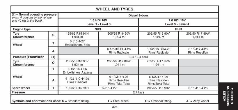
325
AX
LE
S
SU
SP
EN
SIO
NS
TE
ER
ING
WHEEL AND TYRES
Engine type 9HX RHRTyre 195/65 R15 91H 205/55 R16 90V 205/55 R16 90V 205/50 R17 89W Circumference
S1,934 m 1,924 m 1,924 m 1,941 m
T6 J15 4-27
Wheel Embellishers Eole
A6 1/2J16 CH4-26 6 1/2J16 CH4-26 6 1/2J17 4-26
Rims Radicale Rims Radicale Rims ResolfenPressure Front/Rear (1) 2,4 / 2,4 barsTyre 205/55 R16 90V 205/50 R17 89W 205/50 R17 89WCircumference
O1,924 m 1,941 m 1,941 m
T 6 1/2J16 4-26Embellishers Azzana
Wheel6 1/2J16 CH4-26
6 1/2J17 4-26 6 1/2J17 4-26A
Rims RadicaleRims Resolfen Rims ResolfenRims Toka Toka Rims Toka Toka
Spare wheel T 195/65 R15 91H 6 J15 4-27 205/55 R16 90V 6 1/2J16 4-26Pressure 2,7 bars
Symbols and abbreviations used: S = Standard fitting. T = Steel wheel. O = Optional fitting. A = Alloy wheel.
(1) = Normal operating pressure(max. 4 persons in the vehicleand 40 Kg in the boot).
Diesel 3-door
1.6 HDi 16V 2.0 HDi 16VLevel 1 - Level 3 Level 3 - Level 4
UK-C4-page322-360-2004 15/11/04 9:07 Page 325
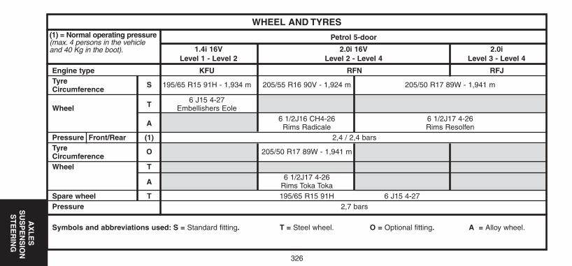
326
AX
LE
SS
US
PE
NS
ION
ST
EE
RIN
G
WHEEL AND TYRES
Engine type KFU RFN RFJTyreCircumference
S 195/65 R15 91H - 1,934 m 205/55 R16 90V - 1,924 m 205/50 R17 89W - 1,941 m
T6 J15 4-27
Wheel Embellishers Eole
A6 1/2J16 CH4-26 6 1/2J17 4-26
Rims Radicale Rims ResolfenPressure Front/Rear (1) 2,4 / 2,4 barsTyreCircumference
O 205/50 R17 89W - 1,941 m
Wheel T
A6 1/2J17 4-26
Rims Toka TokaSpare wheel T 195/65 R15 91H 6 J15 4-27Pressure 2,7 bars
Symbols and abbreviations used: S = Standard fitting. T = Steel wheel. O = Optional fitting. A = Alloy wheel.
(1) = Normal operating pressure(max. 4 persons in the vehicleand 40 Kg in the boot).
Petrol 5-door
1.4i 16V 2.0i 16V 2.0iLevel 1 - Level 2 Level 2 - Level 4 Level 3 - Level 4
UK-C4-page322-360-2004 15/11/04 9:07 Page 326
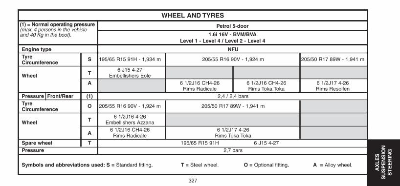
327
AX
LE
S
SU
SP
EN
SIO
NS
TE
ER
ING
WHEEL AND TYRES
Engine type NFUTyreCircumference
S 195/65 R15 91H - 1,934 m 205/55 R16 90V - 1,924 m 205/50 R17 89W - 1,941 m
T6 J15 4-27
Wheel Embellishers EoleA 6 1/2J16 CH4-26 6 1/2J16 CH4-26 6 1/2J17 4-26
Rims Radicale Rims Toka Toka Rims ResolfenPressure Front/Rear (1) 2,4 / 2,4 barsTyreCircumference
O 205/55 R16 90V - 1,924 m 205/50 R17 89W - 1,941 m
T6 1/2J16 4-26
Wheel Embellishers Azzana
A6 1/2J16 CH4-26 6 1/2J17 4-26
Rims Radicale Rims Toka TokaSpare wheel T 195/65 R15 91H 6 J15 4-27Pressure 2,7 bars
Symbols and abbreviations used: S = Standard fitting. T = Steel wheel. O = Optional fitting. A = Alloy wheel.
(1) = Normal operating pressure(max. 4 persons in the vehicleand 40 Kg in the boot).
Petrol 5-door
1.6i 16V - BVM/BVALevel 1 - Level 4 / Level 2 - Level 4
UK-C4-page322-360-2004 15/11/04 9:07 Page 327
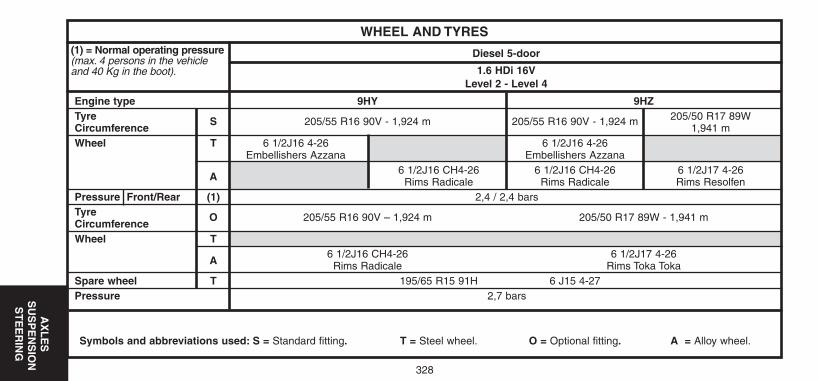
328
AX
LE
SS
US
PE
NS
ION
ST
EE
RIN
G
WHEEL AND TYRES
Engine type 9HY 9HZTyre 205/50 R17 89WCircumference
S 205/55 R16 90V - 1,924 m 205/55 R16 90V - 1,924 m1,941 m
Wheel T 6 1/2J16 4-26 6 1/2J16 4-26Embellishers Azzana Embellishers Azzana
A6 1/2J16 CH4-26 6 1/2J16 CH4-26 6 1/2J17 4-26
Rims Radicale Rims Radicale Rims ResolfenPressure Front/Rear (1) 2,4 / 2,4 barsTyreCircumference
O 205/55 R16 90V – 1,924 m 205/50 R17 89W - 1,941 m
Wheel T
A6 1/2J16 CH4-26 6 1/2J17 4-26
Rims Radicale Rims Toka TokaSpare wheel T 195/65 R15 91H 6 J15 4-27Pressure 2,7 bars
Symbols and abbreviations used: S = Standard fitting. T = Steel wheel. O = Optional fitting. A = Alloy wheel.
(1) = Normal operating pressure(max. 4 persons in the vehicleand 40 Kg in the boot).
Diesel 5-door
1.6 HDi 16VLevel 2 - Level 4
UK-C4-page322-360-2004 15/11/04 9:07 Page 328
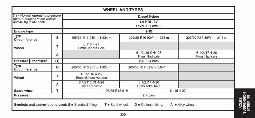
329
AX
LE
S
SU
SP
EN
SIO
NS
TE
ER
ING
WHEEL AND TYRES
Engine type 9HXTyreCircumference
S 195/65 R15 91H – 1,934 m 205/55 R16 90V – 1,924 m 205/50 R17 89W – 1,941 m
T6 J15 4-27
Wheel Embellishers Eole
A6 1/2J16 CH4-26 6 1/2J17 4-26
Rims Radicale Rims RadicalePressure Front/Rear (1) 2,4 / 2,4 barsTyreCircumference
O 205/55 R16 90V – 1,924 m 205/50 R17 89W – 1,941 m
T6 1/2J16 4-26
Wheel Embellishers Azzana
A6 1/2J16 CH4-26 6 1/2J17 4-26
Rims Radicale Rims Toka TokaSpare wheel T 195/65 R15 91H 6 J15 4-27Pressure 2,7 bars
Symbols and abbreviations used: S = Standard fitting. T = Steel wheel. O = Optional fitting. A = Alloy wheel.
(1) = Normal operating pressure(max. 4 persons in the vehicleand 40 Kg in the boot).
Diesel 5-door
1.6 HDi 16VLevel 1 - Level 3
UK-C4-page322-360-2004 15/11/04 9:07 Page 329
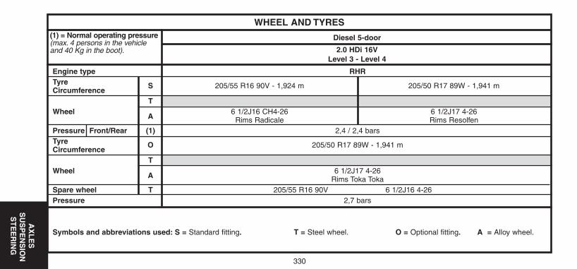
330
AX
LE
SS
US
PE
NS
ION
ST
EE
RIN
G
WHEEL AND TYRES
Engine type RHRTyreCircumference
S 205/55 R16 90V - 1,924 m 205/50 R17 89W - 1,941 m
TWheel
A6 1/2J16 CH4-26 6 1/2J17 4-26
Rims Radicale Rims ResolfenPressure Front/Rear (1) 2,4 / 2,4 barsTyreCircumference
O 205/50 R17 89W - 1,941 m
TWheel
A6 1/2J17 4-26
Rims Toka TokaSpare wheel T 205/55 R16 90V 6 1/2J16 4-26Pressure 2,7 bars
Symbols and abbreviations used: S = Standard fitting. T = Steel wheel. O = Optional fitting. A = Alloy wheel.
(1) = Normal operating pressure(max. 4 persons in the vehicleand 40 Kg in the boot).
Diesel 5-door
2.0 HDi 16VLevel 3 - Level 4
UK-C4-page322-360-2004 15/11/04 9:07 Page 330
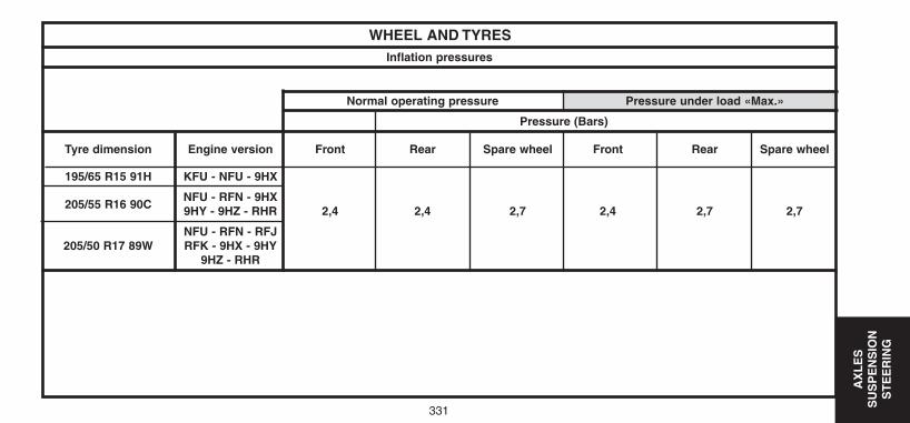
331
AX
LE
S
SU
SP
EN
SIO
NS
TE
ER
ING
WHEEL AND TYRES
Normal operating pressure Pressure under load «Max.»
Pressure (Bars)
Tyre dimension Engine version Front Rear Spare wheel Front Rear Spare wheel
195/65 R15 91H KFU - NFU - 9HX
205/55 R16 90CNFU - RFN - 9HX9HY - 9HZ - RHR 2,4 2,4 2,7 2,4 2,7 2,7
NFU - RFN - RFJ205/50 R17 89W RFK - 9HX - 9HY
9HZ - RHR
Inflation pressures
UK-C4-page322-360-2004 15/11/04 9:07 Page 331
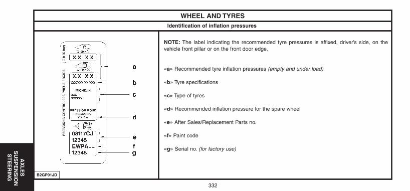
332
AX
LE
SS
US
PE
NS
ION
ST
EE
RIN
G
WHEEL AND TYRESIdentification of inflation pressures
NOTE: The label indicating the recommended tyre pressures is affixed, driver’s side, on thevehicle front pillar or on the front door edge.
«a» Recommended tyre inflation pressures (empty and under load)
«b» Tyre specifications
«c» Type of tyres
«d» Recommended inflation pressure for the spare wheel
«e» After Sales/Replacement Parts no.
«f» Paint code
«g» Serial no. (for factory use)
B2GP01JD
UK-C4-page322-360-2004 15/11/04 9:07 Page 332
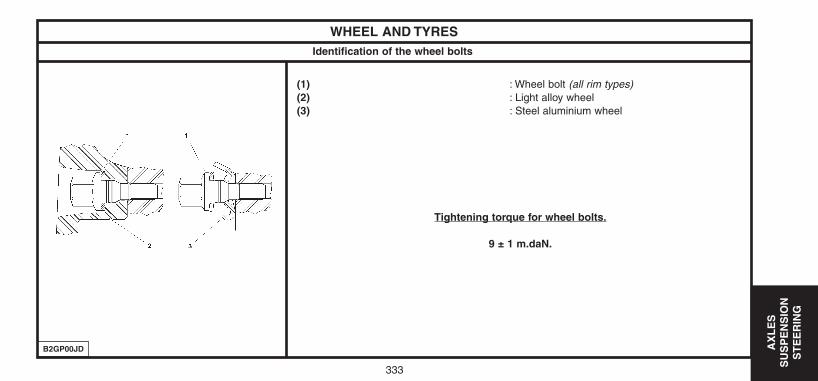
333
AX
LE
S
SU
SP
EN
SIO
NS
TE
ER
ING
WHEEL AND TYRESIdentification of the wheel bolts
(1) : Wheel bolt (all rim types)(2) : Light alloy wheel(3) : Steel aluminium wheel
Tightening torque for wheel bolts.
9 ± 1 m.daN.
B2GP00JD
UK-C4-page322-360-2004 15/11/04 9:07 Page 333
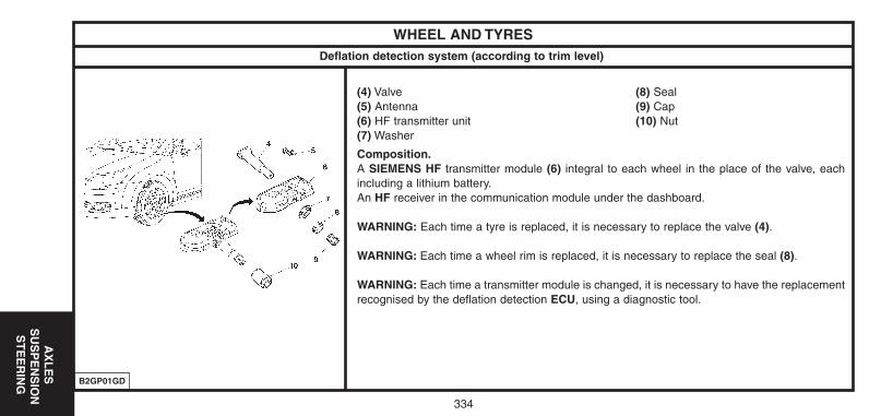
334
AX
LE
SS
US
PE
NS
ION
ST
EE
RIN
G
WHEEL AND TYRESDeflation detection system (according to trim level)
(4) Valve (8) Seal(5) Antenna (9) Cap(6) HF transmitter unit (10) Nut(7) Washer
Composition.A SIEMENS HF transmitter module (6) integral to each wheel in the place of the valve, eachincluding a lithium battery.An HF receiver in the communication module under the dashboard.
WARNING: Each time a tyre is replaced, it is necessary to replace the valve (4).
WARNING: Each time a wheel rim is replaced, it is necessary to replace the seal (8).
WARNING: Each time a transmitter module is changed, it is necessary to have the replacementrecognised by the deflation detection ECU, using a diagnostic tool.
B2GP01GD
UK-C4-page322-360-2004 15/11/04 9:07 Page 334
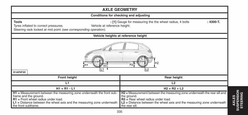
335
AX
LE
S
SU
SP
EN
SIO
NS
TE
ER
ING
AXLE GEOMETRYConditions for checking and adjusting
Vehicle heights at reference height
Rear heightFront height
L2L1
Tools : [1] Gauge for measuring the the wheel radius, 4 bolts : 4300-T.Tyres inflated to correct pressures. Vehicle at reference height.Steering rack locked at mid point (see corresponding operation).
H1 = R1 - L1H1 = Measurement between the measuring zone underneath the front sub-frame and the ground.R1 = Front wheel radius under load.L1 = Distance between the wheel axis and the measuring zone underneaththe front subframe.
H2 = R2 + L2H2 = Measurement between the measuring zone underneath the rear sill andthe ground.R2 = Rear wheel radius under load.L2 = Distance between the wheel axis and the measuring zone underneaththe rear sill.
E1AP0F3D
UK-C4-page322-360-2004 15/11/04 9:07 Page 335
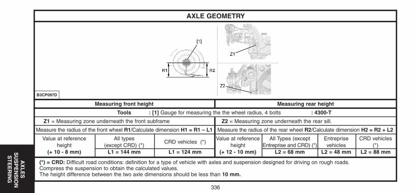
336
AX
LE
SS
US
PE
NS
ION
ST
EE
RIN
G
AXLE GEOMETRY
B3CP097D
Measuring front height Measuring rear height
Tools : [1] Gauge for measuring the the wheel radius, 4 bolts : 4300-T
Z1 = Measuring zone underneath the front subframe Z2 = Measuring zone underneath the rear sill.
Measure the radius of the front wheel R1/Calculate dimension H1 = R1 – L1 Measure the radius of the rear wheel R2/Calculate dimension H2 = R2 + L2
Value at reference All typesCRD vehicles (*)
Value at reference All Types (except Entreprise CRD vehicles height (except CRD) (*) height Entreprise and CRD) (*) vehicles (*)
(+ 10 - 8 mm) L1 = 144 mm L1 = 124 mm (+ 12 - 10 mm) L2 = 68 mm L2 = 48 mm L2 = 88 mm
(*) = CRD: Difficult road conditions: definition for a type of vehicle with axles and suspension designed for driving on rough roads.Compress the suspension to obtain the calculated values.The height difference between the two axle dimensions should be less than 10 mm.
UK-C4-page322-360-2004 15/11/04 9:07 Page 336
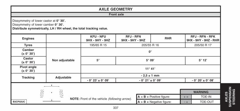
337
AX
LE
S
SU
SP
EN
SIO
NS
TE
ER
ING
A < B = Positive figure: + = TOE-IN
A > B = Negative figure: - = TOE-OUT
WARNING
AXLE GEOMETRYFront axle
Dissymmetry of lower castor at 0° 30’.Dissymmetry of lower camber 0° 30’.Distribute symmetrically, LH / RH wheel, the total tracking value.
EnginesKFU - NFU RFJ - RFN RFJ - RFN - RFK
9HX - 9HY - 9HZ 9HX - 9HY - 9HZRHR
9HX - 9HY - 9HZ - RHR
Tyres 195/65 R 15 205/55 R 16 205/50 R 17
Camber(± 0° 30’)
0°
Castor(± 0° 30’)
Non adjustable 5° 5° 09’ 5° 12’
Pivot angle(± 0° 30’)
11° 41’
Tracking Adjustable- 2,5 ± 1 mm
- 0° 23’ ± 0° 09’ - 0° 21’ ± 0° 09’ - 0° 20’ ± 0° 08’
NOTE: Front of the vehicle (following arrow).B3CP02UC
UK-C4-page322-360-2004 15/11/04 9:07 Page 337
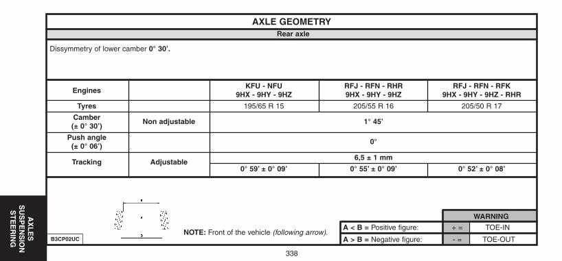
338
AX
LE
S
SU
SP
EN
SIO
NS
TE
ER
ING
A < B = Positive figure: + = TOE-IN
A > B = Negative figure: - = TOE-OUT
WARNING
AXLE GEOMETRYRear axle
Dissymmetry of lower camber 0° 30’.
EnginesKFU - NFU RFJ - RFN - RHR RFJ - RFN - RFK
9HX - 9HY - 9HZ 9HX - 9HY - 9HZ 9HX - 9HY - 9HZ - RHR
Tyres 195/65 R 15 205/55 R 16 205/50 R 17
Camber(± 0° 30’)
Non adjustable 1° 45’
Push angle(± 0° 06’)
0°
Tracking Adjustable6,5 ± 1 mm
0° 59’ ± 0° 09’ 0° 55’ ± 0° 09’ 0° 52’ ± 0° 08’
NOTE: Front of the vehicle (following arrow).B3CP02UC
UK-C4-page322-360-2004 15/11/04 9:07 Page 338
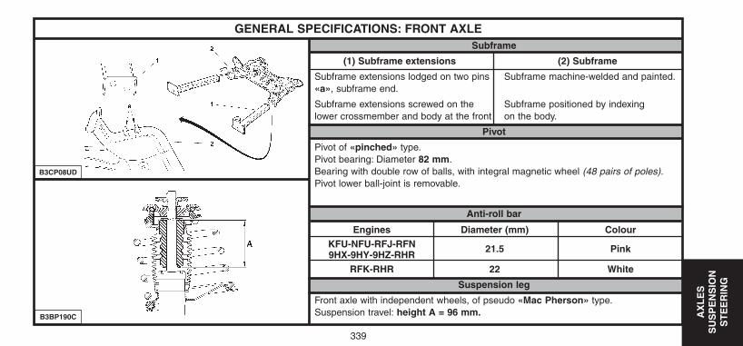
339
AX
LE
S
SU
SP
EN
SIO
NS
TE
ER
ING
GENERAL SPECIFICATIONS: FRONT AXLESubframe
(1) Subframe extensions (2) Subframe
Subframe extensions lodged on two pins Subframe machine-welded and painted.«a», subframe end.
Subframe extensions screwed on the Subframe positioned by indexinglower crossmember and body at the front on the body.
Pivot
Pivot of «pinched» type.Pivot bearing: Diameter 82 mm.Bearing with double row of balls, with integral magnetic wheel (48 pairs of poles).Pivot lower ball-joint is removable.
Anti-roll bar
Engines Diameter (mm) ColourKFU-NFU-RFJ-RFN9HX-9HY-9HZ-RHR
21.5 Pink
RFK-RHR 22 White
Suspension leg
Front axle with independent wheels, of pseudo «Mac Pherson» type.Suspension travel: height A = 96 mm.B3BP190C
B3CP08UD
UK-C4-page322-360-2004 15/11/04 9:07 Page 339
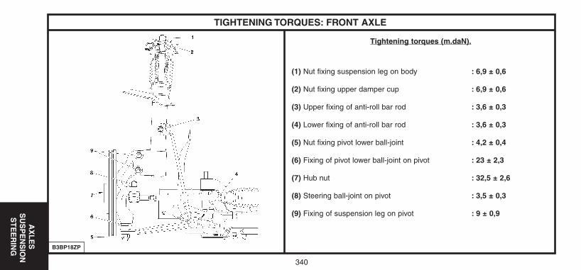
340
AX
LE
SS
US
PE
NS
ION
ST
EE
RIN
G
TIGHTENING TORQUES: FRONT AXLE
Tightening torques (m.daN).
(1) Nut fixing suspension leg on body : 6,9 ± 0,6
(2) Nut fixing upper damper cup : 6,9 ± 0,6
(3) Upper fixing of anti-roll bar rod : 3,6 ± 0,3
(4) Lower fixing of anti-roll bar rod : 3,6 ± 0,3
(5) Nut fixing pivot lower ball-joint : 4,2 ± 0,4
(6) Fixing of pivot lower ball-joint on pivot : 23 ± 2,3
(7) Hub nut : 32,5 ± 2,6
(8) Steering ball-joint on pivot : 3,5 ± 0,3
(9) Fixing of suspension leg on pivot : 9 ± 0,9
B3BP18ZP
UK-C4-page322-360-2004 15/11/04 9:07 Page 340
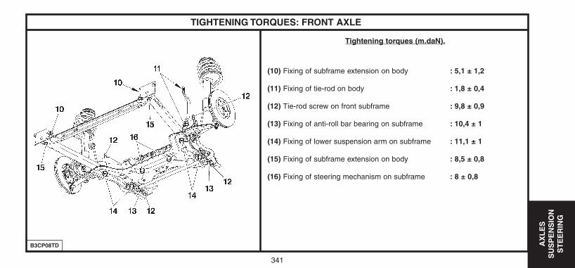
341
AX
LE
S
SU
SP
EN
SIO
NS
TE
ER
ING
TIGHTENING TORQUES: FRONT AXLE
Tightening torques (m.daN).
(10) Fixing of subframe extension on body : 5,1 ± 1,2
(11) Fixing of tie-rod on body : 1,8 ± 0,4
(12) Tie-rod screw on front subframe : 9,8 ± 0,9
(13) Fixing of anti-roll bar bearing on subframe : 10,4 ± 1
(14) Fixing of lower suspension arm on subframe : 11,1 ± 1
(15) Fixing of subframe extension on body : 8,5 ± 0,8
(16) Fixing of steering mechanism on subframe : 8 ± 0,8
B3CP08TD
UK-C4-page322-360-2004 15/11/04 9:07 Page 341
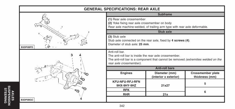
342
AX
LE
S
SU
SP
EN
SIO
NS
TE
ER
ING
GENERAL SPECIFICATIONS: REAR AXLESubframe
(1) Rear axle crossmember(2) Yoke fixing rear axle crossmember on bodyRear axle machine-welded, of trailing arm type with rear axle deformable.
Stub axle
(3) Stub axleStub axle connected on the rear axle, fixed by 4 screws (4).Diameter of stub axle: 25 mm.
Anti-roll bar.The anti-roll bar is inside the rear axle crossmember.The anti-roll bar is a component that cannot be removed (extremities welded on therear axle crossmember).
Anti-roll bars
Engines Diameter (mm) Crossmember plate(interior x exterior) thickness (mm)
KFU-NFU-RFJ-RFN9HX-9HY-9HZ 21x27
5
RFK6
RHR 21x
B3DP0BGC
B3DP0BFD
UK-C4-page322-360-2004 15/11/04 9:07 Page 342
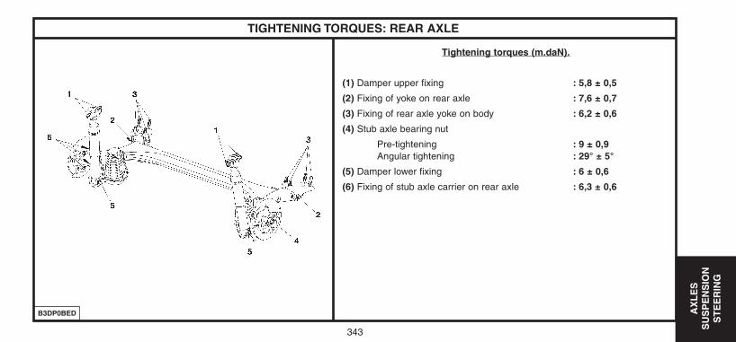
343
AX
LE
S
SU
SP
EN
SIO
NS
TE
ER
ING
TIGHTENING TORQUES: REAR AXLE
Tightening torques (m.daN).
(1) Damper upper fixing : 5,8 ± 0,5
(2) Fixing of yoke on rear axle : 7,6 ± 0,7
(3) Fixing of rear axle yoke on body : 6,2 ± 0,6
(4) Stub axle bearing nut
Pre-tightening : 9 ± 0,9Angular tightening : 29° ± 5°
(5) Damper lower fixing : 6 ± 0,6
(6) Fixing of stub axle carrier on rear axle : 6,3 ± 0,6
B3DP0BED
UK-C4-page322-360-2004 15/11/04 9:07 Page 343
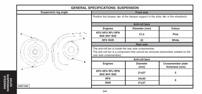
344
AX
LE
SS
US
PE
NS
ION
ST
EE
RIN
G
GENERAL SPECIFICATIONS: SUSPENSIONFront axle
Position the bosses «a» of the damper support in the slots «b» in the wheelarch.
Anti-roll bars
Engines Diameter (mm) Colour
KFU NFU RFJ RFN9HX 9HY 9HZ
21,5 Pink
RFK RHR 22 White
Rear axle
The anti-roll bar is inside the rear axle crossmember.The anti-roll bar is a component that cannot be removed (extremities welded on therear axle crossmember).
Anti-roll bars
Engines Diameter Crossmember plate(mm) thickness (mm)
KFU NFU RFJ RFN9HX 9HY 9HZ
21x27 5
RFK 24x306
RHR 21x27B3BP19QD
Suspension leg angle
UK-C4-page322-360-2004 15/11/04 9:07 Page 344
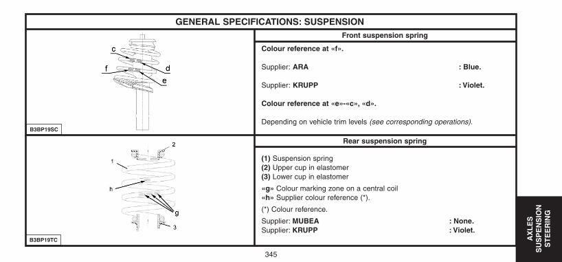
345
AX
LE
S
SU
SP
EN
SIO
NS
TE
ER
ING
GENERAL SPECIFICATIONS: SUSPENSION
Colour reference at «f».
Supplier: ARA : Blue.
Supplier: KRUPP : Violet.
Colour reference at «e»-«c», «d».
Depending on vehicle trim levels (see corresponding operations).
(1) Suspension spring(2) Upper cup in elastomer(3) Lower cup in elastomer
«g» Colour marking zone on a central coil«h» Supplier colour reference (*).
(*) Colour reference.
Supplier: MUBEA : None.Supplier: KRUPP : Violet.
B3BP19TC
Front suspension spring
B3BP19SC
Rear suspension spring
UK-C4-page322-360-2004 15/11/04 9:07 Page 345
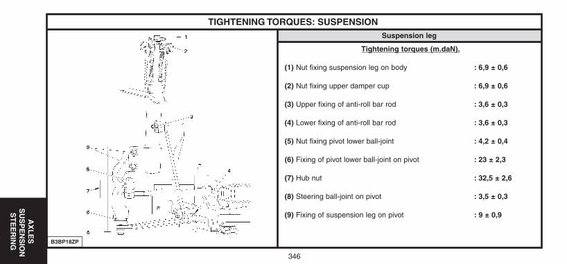
346
AX
LE
SS
US
PE
NS
ION
ST
EE
RIN
G
TIGHTENING TORQUES: SUSPENSION
Tightening torques (m.daN).
(1) Nut fixing suspension leg on body : 6,9 ± 0,6
(2) Nut fixing upper damper cup : 6,9 ± 0,6
(3) Upper fixing of anti-roll bar rod : 3,6 ± 0,3
(4) Lower fixing of anti-roll bar rod : 3,6 ± 0,3
(5) Nut fixing pivot lower ball-joint : 4,2 ± 0,4
(6) Fixing of pivot lower ball-joint on pivot : 23 ± 2,3
(7) Hub nut : 32,5 ± 2,6
(8) Steering ball-joint on pivot : 3,5 ± 0,3
(9) Fixing of suspension leg on pivot : 9 ± 0,9
B3BP18ZP
Suspension leg
UK-C4-page322-360-2004 15/11/04 9:07 Page 346
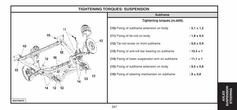
347
AX
LE
S
SU
SP
EN
SIO
NS
TE
ER
ING
TIGHTENING TORQUES: SUSPENSION
Tightening torques (m.daN).
(10) Fixing of subframe extension on body : 5,1 ± 1,2
(11) Fixing of tie-rod on body : 1,8 ± 0,4
(12) Tie-rod screw on front subframe : 9,8 ± 0,9
(13) Fixing of anti-roll bar bearing on subframe : 10,4 ± 1
(14) Fixing of lower suspension arm on subframe : 11,1 ± 1
(15) Fixing of subframe extension on body : 8,5 ± 0,8
(16) Fixing of steering mechanism on subframe : 8 ± 0,8
B3CP08TD
Subframe
UK-C4-page322-360-2004 15/11/04 9:07 Page 347
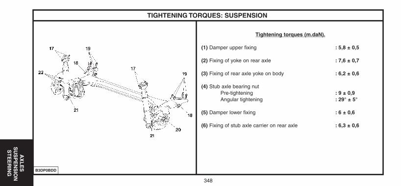
348
AX
LE
SS
US
PE
NS
ION
ST
EE
RIN
G
TIGHTENING TORQUES: SUSPENSION
Tightening torques (m.daN).
(1) Damper upper fixing : 5,8 ± 0,5
(2) Fixing of yoke on rear axle : 7,6 ± 0,7
(3) Fixing of rear axle yoke on body : 6,2 ± 0,6
(4) Stub axle bearing nutPre-tightening : 9 ± 0,9Angular tightening : 29° ± 5°
(5) Damper lower fixing : 6 ± 0,6
(6) Fixing of stub axle carrier on rear axle : 6,3 ± 0,6
B3DP0BDD
UK-C4-page322-360-2004 15/11/04 9:07 Page 348
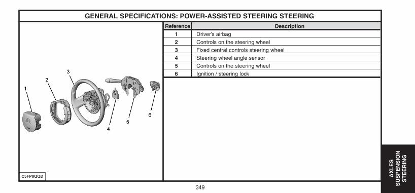
349
AX
LE
SS
US
PE
NS
ION
ST
EE
RIN
G
GENERAL SPECIFICATIONS: POWER-ASSISTED STEERING STEERINGReference Description
1 Driver’s airbag
2 Controls on the steering wheel
3 Fixed central controls steering wheel
4 Steering wheel angle sensor
5 Controls on the steering wheel
6 Ignition / steering lock
C5FP0QQD
UK-C4-page322-360-2004 15/11/04 9:07 Page 349
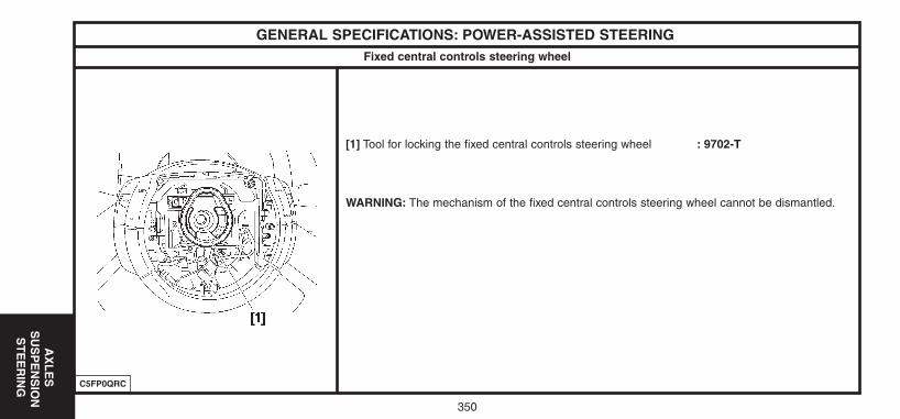
350
AX
LE
SS
US
PE
NS
ION
ST
EE
RIN
G
GENERAL SPECIFICATIONS: POWER-ASSISTED STEERING
[1] Tool for locking the fixed central controls steering wheel : 9702-T
WARNING: The mechanism of the fixed central controls steering wheel cannot be dismantled.
C5FP0QRC
Fixed central controls steering wheel
UK-C4-page322-360-2004 15/11/04 9:07 Page 350
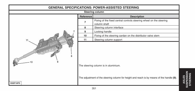
351
AX
LE
S
SU
SP
EN
SIO
NS
TE
ER
ING
GENERAL SPECIFICATIONS: POWER-ASSISTED STEERING
Reference Description
7Fixing of the fixed central controls steering wheel on the steeringcolumn shaft
8 Steering column interface
9 Locking handle
10 Fixing of the steering cardan on the distributor valve stem
11 Steering column support
The steering column is in aluminium.
The adjustment of the steering column for height and reach is by means of the handle (9).
B3EP16PD
Steering column
UK-C4-page322-360-2004 15/11/04 9:07 Page 351
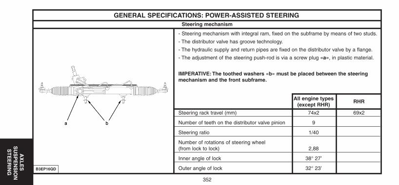
352
AX
LE
SS
US
PE
NS
ION
ST
EE
RIN
G
GENERAL SPECIFICATIONS: POWER-ASSISTED STEERING
- Steering mechanism with integral ram, fixed on the subframe by means of two studs.
- The distributor valve has groove technology.
- The hydraulic supply and return pipes are fixed on the distributor valve by a flange.
- The adjustment of the steering push-rod is via a screw plug «a», in plastic material.
IMPERATIVE: The toothed washers «b» must be placed between the steering mechanism and the front subframe.
All engine types(except RHR)
RHR
Steering rack travel (mm) 74x2 69x2
Number of teeth on the distributor valve pinion 9
Steering ratio 1/40
Number of rotations of steering wheel(from lock to lock) 2,88
Inner angle of lock 38° 27’
Outer angle of lock 32° 23’B3EP16QD
Steering mechanism
UK-C4-page322-360-2004 15/11/04 9:07 Page 352
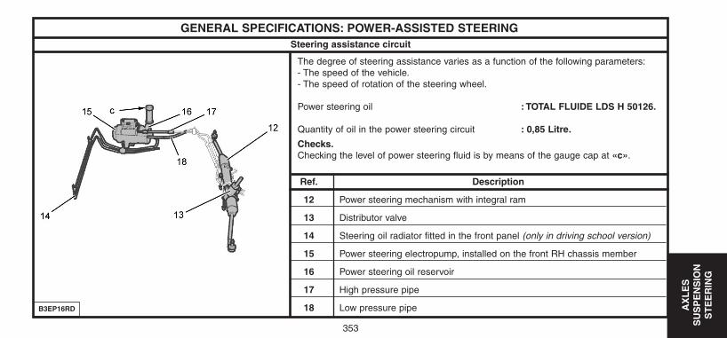
353
AX
LE
S
SU
SP
EN
SIO
NS
TE
ER
ING
GENERAL SPECIFICATIONS: POWER-ASSISTED STEERING
The degree of steering assistance varies as a function of the following parameters:- The speed of the vehicle.- The speed of rotation of the steering wheel.
Power steering oil : TOTAL FLUIDE LDS H 50126.
Quantity of oil in the power steering circuit : 0,85 Litre.
Checks.Checking the level of power steering fluid is by means of the gauge cap at «c».
Ref. Description
12 Power steering mechanism with integral ram
13 Distributor valve
14 Steering oil radiator fitted in the front panel (only in driving school version)
15 Power steering electropump, installed on the front RH chassis member
16 Power steering oil reservoir
17 High pressure pipe
18 Low pressure pipeB3EP16RD
Steering assistance circuit
UK-C4-page322-360-2004 15/11/04 9:07 Page 353
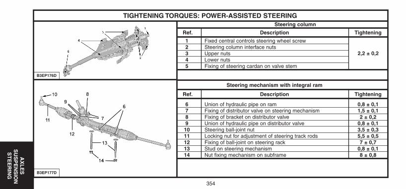
354
AX
LE
SS
US
PE
NS
ION
ST
EE
RIN
G
TIGHTENING TORQUES: POWER-ASSISTED STEERINGSteering column
Ref. Description Tightening
1 Fixed central controls steering wheel screw 2,2 ± 0,22 Steering column interface nuts3 Upper nuts4 Lower nuts5 Fixing of steering cardan on valve stem
Steering mechanism with integral ram
Ref. Description Tightening
6 Union of hydraulic pipe on ram 0,8 ± 0,17 Fixing of distributor valve on steering mechanism 1,5 ± 0,18 Fixing of bracket on distributor valve 2 ± 0,29 Union of hydraulic pipe on distributor valve 0,8 ± 0,110 Steering ball-joint nut 3,5 ± 0,311 Locking nut for adjustment of steering track rods 5,5 ± 0,512 Fixing of ball-joint on steering rack 7 ± 0,713 Stud on steering mechanism 0,8 ± 0,114 Nut fixing mechanism on subframe 8 ± 0,8
B3EP177D
B3EP176D
2,2 ± 0,2
UK-C4-page322-360-2004 15/11/04 9:07 Page 354
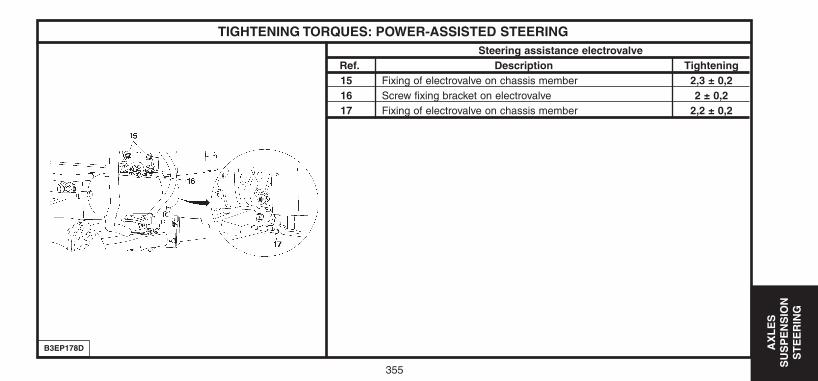
355
AX
LE
S
SU
SP
EN
SIO
NS
TE
ER
ING
TIGHTENING TORQUES: POWER-ASSISTED STEERINGSteering assistance electrovalve
Ref. Description Tightening15 Fixing of electrovalve on chassis member 2,3 ± 0,216 Screw fixing bracket on electrovalve 2 ± 0,217 Fixing of electrovalve on chassis member 2,2 ± 0,2
B3EP178D
UK-C4-page322-360-2004 15/11/04 9:07 Page 355
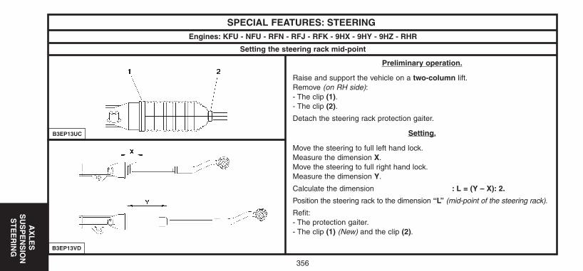
356
AX
LE
SS
US
PE
NS
ION
ST
EE
RIN
G
SPECIAL FEATURES: STEERING
Preliminary operation.
Raise and support the vehicle on a two-column lift.Remove (on RH side):- The clip (1).- The clip (2).
Detach the steering rack protection gaiter.
Setting.
Move the steering to full left hand lock.Measure the dimension X.Move the steering to full right hand lock.Measure the dimension Y.
Calculate the dimension : L = (Y – X): 2.
Position the steering rack to the dimension “L” (mid-point of the steering rack).
Refit:- The protection gaiter.- The clip (1) (New) and the clip (2).
B3EP13VD
Engines: KFU - NFU - RFN - RFJ - RFK - 9HX - 9HY - 9HZ - RHR
B3EP13UC
Setting the steering rack mid-point
UK-C4-page322-360-2004 15/11/04 9:07 Page 356
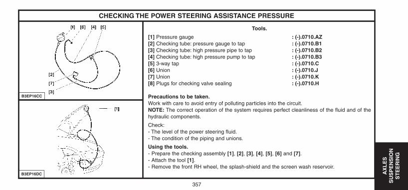
357
AX
LE
S
SU
SP
EN
SIO
NS
TE
ER
ING
CHECKING THE POWER STEERING ASSISTANCE PRESSURE
Tools.
[1] Pressure gauge : (-).0710.AZ[2] Checking tube: pressure gauge to tap : (-).0710.B1[3] Checking tube: high pressure pipe to tap : (-).0710.B2[4] Checking tube: high pressure pump to tap : (-).0710.B3[5] 3-way tap : (-).0710.C[6] Union : (-).0710.J[7] Union : (-).0710.K[8] Plugs for checking valve sealing : (-).0710.H
Precautions to be taken.Work with care to avoid entry of polluting particles into the circuit.NOTE: The correct operation of the system requires perfect cleanliness of the fluid and of thehydraulic components.
Check:- The level of the power steering fluid.- The condition of the piping and unions.
Using the tools.- Prepare the checking assembly [1], [2], [3], [4], [5], [6] and [7].- Attach the tool [1].- Remove the front RH wheel, the splash-shield and the screen wash reservoir.
B3EP16CC
B3EP16DC
UK-C4-page322-360-2004 15/11/04 9:07 Page 357
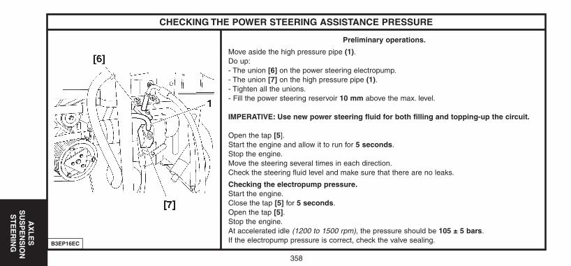
358
AX
LE
SS
US
PE
NS
ION
ST
EE
RIN
G
CHECKING THE POWER STEERING ASSISTANCE PRESSURE
Preliminary operations.
Move aside the high pressure pipe (1).Do up:- The union [6] on the power steering electropump.- The union [7] on the high pressure pipe (1).- Tighten all the unions.- Fill the power steering reservoir 10 mm above the max. level.
IMPERATIVE: Use new power steering fluid for both filling and topping-up the circuit.
Open the tap [5].Start the engine and allow it to run for 5 seconds.Stop the engine.Move the steering several times in each direction.Check the steering fluid level and make sure that there are no leaks.
Checking the electropump pressure.Start the engine.Close the tap [5] for 5 seconds.Open the tap [5].Stop the engine.At accelerated idle (1200 to 1500 rpm), the pressure should be 105 ± 5 bars.If the electropump pressure is correct, check the valve sealing.B3EP16EC
UK-C4-page322-360-2004 15/11/04 9:07 Page 358
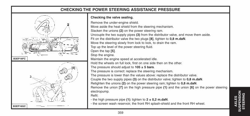
359
AX
LE
S
SU
SP
EN
SIO
NS
TE
ER
ING
CHECKING THE POWER STEERING ASSISTANCE PRESSURE
Checking the valve sealing.
Remove the under-engine shield.Move aside the heat shield from the steering mechanism.Slacken the unions (2) on the power steering ram.Uncouple the two supply pipes (3) from the distributor valve, and move them aside.Fit on the distributor valve the two plugs [8], tighten to 0,8 m.daN.Move the steering slowly from lock to lock, to drain the ram.Top up the level of the power steering fluid.Open the tap [5].Stop the engine.Maintain the engine speed at accelerated idle.Hold the wheels on full lock, first on one side then on the other.The pressure should adjust to 105 ± 5 bars.The pressure is correct: replace the steering mechanism.The pressure is lower than the values above: replace the distributor valve.Couple the two supply pipes (3) on the distributor valve; tighten to 0,8 m.daN.Retighten the unions (2) on the power steering ram; tighten to 0,8 m.daN.Remove the union [7] on the high pressure pipe (1) and the union [6] on the power steeringelectropump.Refit:- the high pressure pipe (1); tighten to 2 ± 0,2 m.daN.- the screen wash reservoir, the front RH splash-shield and the front RH wheel.
B3EP16FC
B3EP16GC
UK-C4-page322-360-2004 15/11/04 9:07 Page 359
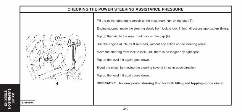
AX
LE
SS
US
PE
NS
ION
ST
EE
RIN
G
CHECKING THE POWER STEERING ASSISTANCE PRESSURE
Fill the power steering reservoir to the max. mark «a» on the cap (4).
Engine stopped, move the steering slowly from lock to lock, in both directions approx. ten times.
Top up the fluid to the max. mark «a» on the cap (4).
Run the engine at idle for 3 minutes, without any action on the steering wheel.
Move the steering from lock to lock, until there is no longer any tight spot.
Top up the level if it again goes down.
Bleed the circuit by moving the steering several times in each direction.
Top up the level if it again goes down.
IMPERATIVE: Use new power steering fluid for both filling and topping-up the circuit.
B3EP16HC
360
UK-C4-page322-360-2004 15/11/04 9:07 Page 360
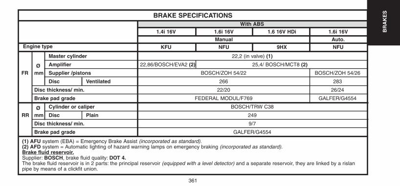
361
BR
AK
ES
22,2 (in valve) (1)
22,86/BOSCH/EVA2 (2) 25,4/ BOSCH/MCT8 (2)
BOSCH/ZOH 54/22 BOSCH/ZOH 54/26
266 283
22/20 26/24
FEDERAL MODUL/F769 GALFER/G4554
BOSCH/TRW C38
249
9/7
GALFER/G4554
BRAKE SPECIFICATIONS
Master cylinder
Ø Amplifier
FR mm Supplier /pistons
Disc Ventilated
Disc thickness/ min.
Brake pad grade
Ø Cylinder or caliper
RR mm Disc Plain
Disc thickness/ min.
Brake pad grade
With ABS1.4i 16V 1.6i 16V 1.6 16V HDi 1.6i 16V
Manual Auto.KFU NFU 9HX NFUEngine type
(1) AFU system (EBA) = Emergency Brake Assist (incorporated as standard).(2) AFD system = Automatic lighting of hazard warning lamps on emergency braking (incorporated as standard).Brake fluid reservoir.Supplier: BOSCH, brake fluid quality: DOT 4.The brake fluid reservoir is in 2 parts: the principal reservoir (equipped with a level detector) and a separate reservoir, they are linked by a rislanpipe by means of a clickfit union.
UK-C4-PAGE361-375-2004 15/11/04 9:09 Page 361
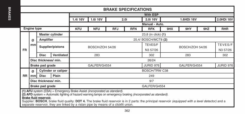
362
BR
AK
ES
23,8 (in click) (1)
25,4/ BOSCH/MCT8 (2)
BOSCH/ZOH 54/26TEVES/F
BOSCH/ZOH 54/26TEVES/F
N3 57/26 N3 57/26
283 302 283 302
26/24
GALFER/G4554 JURID 976 GALFER/G4554 JURID 976
BOSCH/TRW C38
249
9/7
GALFER/G4554
BRAKE SPECIFICATIONS
Master cylinder
Ø Amplifier
mmSupplier/pistons
FR
Disc Ventilated
Disc thickness/ min.
Brake pad grade
Ø Cylinder or caliper
RR mm Disc Plain
Disc thickness/ min.
Brake pad grade
With ESP1.4i 16V 1.6i 16V 2.0i 2.0i 16V 1.6HDi 16V 2.0HDi 16V
Manual - Auto.KFU NFU RFJ RFN RFK 9HX 9HY 9HZ RHREngine type
(1) AFU system (EBA) = Emergency Brake Assist (incorporated as standard).(2) AFD system = Automatic lighting of hazard warning lamps on emergency braking (incorporated as standard).Brake fluid reservoir.Supplier: BOSCH, brake fluid quality: DOT 4. The brake fluid reservoir is in 2 parts: the principal reservoir (equipped with a level detector) and aseparate reservoir, they are linked by a rislan pipe by means of a clickfit union.
UK-C4-PAGE361-375-2004 15/11/04 9:09 Page 362
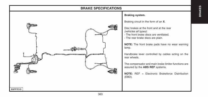
363
BR
AK
ES
B3FP7E1D
BRAKE SPECIFICATIONS
Braking system.
Braking circuit in the form of an X.
Disc brakes at the front and at the rear(vehicles all types):- The front brake discs are ventilated.- The rear brake discs are plain.
NOTE: The front brake pads have no wear warninglamp.
Handbrake lever controlled by cables acting on therear wheels.
The compensator and main brake limiter functions areassured by the ABS REF systems.
NOTE: REF = Electronic Brakeforce Distribution(EBD).
UK-C4-PAGE361-375-2004 15/11/04 9:09 Page 363
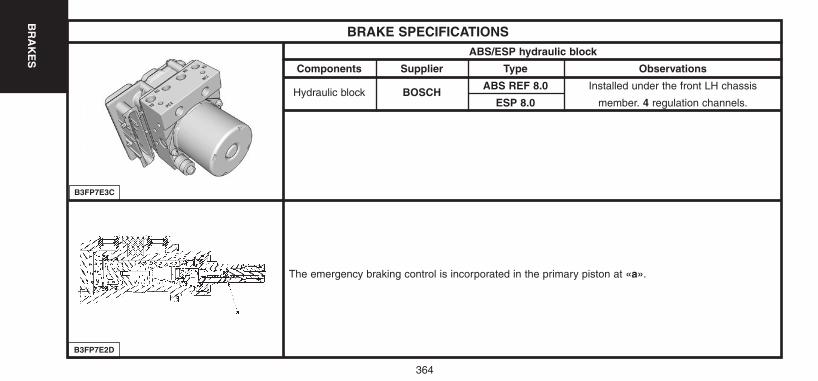
364
BR
AK
ES
B3FP7E2D
BRAKE SPECIFICATIONSABS/ESP hydraulic block
Components Supplier Type Observations
Hydraulic block BOSCHABS REF 8.0 Installed under the front LH chassis
ESP 8.0 member. 4 regulation channels.
The emergency braking control is incorporated in the primary piston at «a».
B3FP7E3C
UK-C4-PAGE361-375-2004 15/11/04 9:09 Page 364
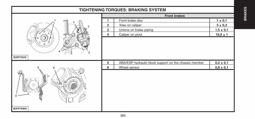
365
BR
AK
ESTIGHTENING TORQUES: BRAKING SYSTEM
Front brakes1 Front brake disc 1 ± 0,12 Yoke on caliper 3 ± 0,33 Unions on brake piping 1,5 ± 0,14 Caliper on pivot 10,5 ± 1
5 ABS/ESP hydraulic block support on the chassis member 0,2 ± 0,16 Wheel sensor 0,8 ± 0,1
B3FP7DVD
B3FP7DWD
UK-C4-PAGE361-375-2004 15/11/04 9:09 Page 365
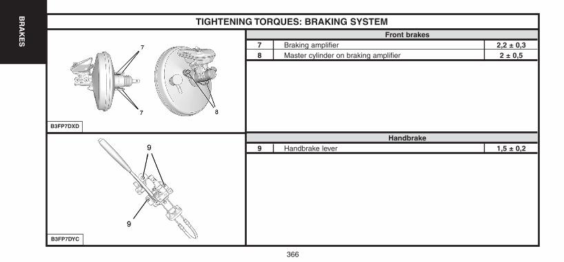
366
BR
AK
ES
TIGHTENING TORQUES: BRAKING SYSTEMFront brakes
7 Braking amplifier 2,2 ± 0,38 Master cylinder on braking amplifier 2 ± 0,5
Handbrake9 Handbrake lever 1,5 ± 0,2
B3FP7DXD
B3FP7DYC
UK-C4-PAGE361-375-2004 15/11/04 9:09 Page 366
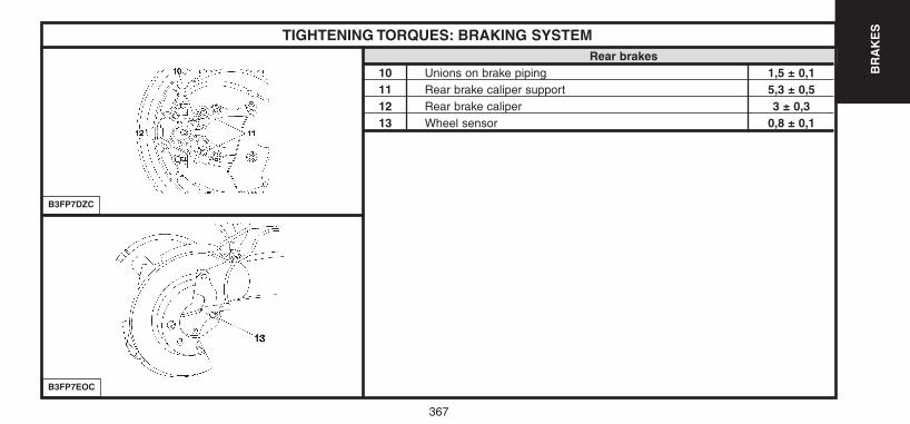
367
BR
AK
ESTIGHTENING TORQUES: BRAKING SYSTEM
B3FP7DZC
B3FP7EOC
Rear brakes10 Unions on brake piping 1,5 ± 0,111 Rear brake caliper support 5,3 ± 0,512 Rear brake caliper 3 ± 0,313 Wheel sensor 0,8 ± 0,1
UK-C4-PAGE361-375-2004 15/11/04 9:09 Page 367
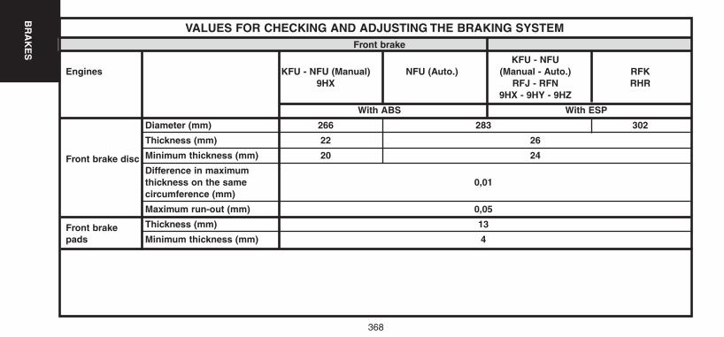
368
BR
AK
ES
VALUES FOR CHECKING AND ADJUSTING THE BRAKING SYSTEMFront brake
KFU - NFUEngines KFU - NFU (Manual) NFU (Auto.) (Manual - Auto.) RFK
9HX RFJ - RFN RHR9HX - 9HY - 9HZ
With ABS With ESP
Diameter (mm) 266 283 302
Thickness (mm) 22 26
Front brake disc Minimum thickness (mm) 20 24
Difference in maximum thickness on the same 0,01circumference (mm)
Maximum run-out (mm) 0,05
Front brake Thickness (mm) 13
pads Minimum thickness (mm) 4
UK-C4-PAGE361-375-2004 15/11/04 9:09 Page 368
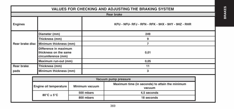
369
BR
AK
ESVALUES FOR CHECKING AND ADJUSTING THE BRAKING SYSTEM
Rear brake
Engines KFU - NFU- RFJ - RFN - RFK - 9HX - 9HY - 9HZ - RHR
Diameter (mm) 249
Thickness (mm) 9
Rear brake disc Minimum thickness (mm) 7
Difference in maximum thickness on the same 0,01circumference (mm)
Maximum run-out (mm) 0,05
Rear brake Thickness (mm) 11
pads Minimum thickness (mm) 3
Vacuum pump pressure
Engine oil temperature Minimum vacuumMaximum time (in seconds) to attain the minimum
vacuum
80°C ± 5°C500 mbars 4,5 seconds
800 mbars 18 seconds
UK-C4-PAGE361-375-2004 15/11/04 9:09 Page 369
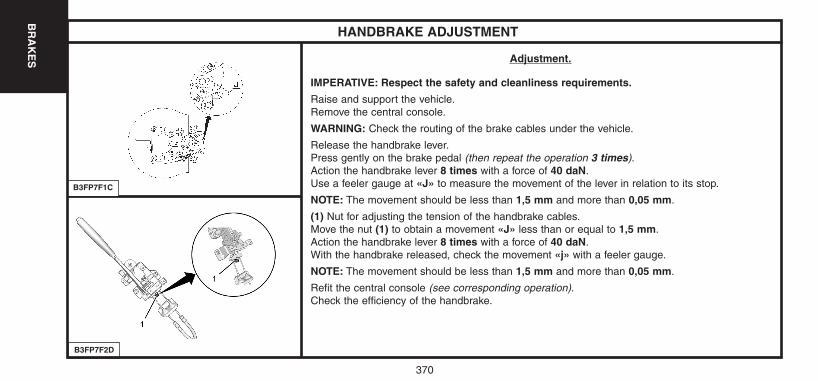
370
BR
AK
ES
HANDBRAKE ADJUSTMENT
Adjustment.
IMPERATIVE: Respect the safety and cleanliness requirements.
Raise and support the vehicle.Remove the central console.
WARNING: Check the routing of the brake cables under the vehicle.
Release the handbrake lever.Press gently on the brake pedal (then repeat the operation 3 times).Action the handbrake lever 8 times with a force of 40 daN.Use a feeler gauge at «J» to measure the movement of the lever in relation to its stop.
NOTE: The movement should be less than 1,5 mm and more than 0,05 mm.
(1) Nut for adjusting the tension of the handbrake cables.Move the nut (1) to obtain a movement «J» less than or equal to 1,5 mm.Action the handbrake lever 8 times with a force of 40 daN.With the handbrake released, check the movement «j» with a feeler gauge.
NOTE: The movement should be less than 1,5 mm and more than 0,05 mm.
Refit the central console (see corresponding operation).Check the efficiency of the handbrake.
B3FP7F1C
B3FP7F2D
UK-C4-PAGE361-375-2004 15/11/04 9:09 Page 370
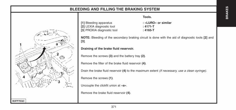
371
BR
AK
ES
B3FP7EQC
BLEEDING AND FILLING THE BRAKING SYSTEM
Tools.
[1] Bleeding apparatus : «LURO» or similar[2] LEXIA diagnostic tool : 4171-T[3] PROXIA diagnostic tool : 4165-T
NOTE: Bleeding of the secondary braking circuit is done with the aid of diagnostic tools [2] and[3].
Draining of the brake fluid reservoir.
Remove the screws (3) and the battery tray (2).
Remove the filter of the brake fluid reservoir (4).
Drain the brake fluid reservoir (4) to the maximum extent (if necessary, use a clean syringe).
Remove the screws (1).
Uncouple the clickfit union at «a».
Remove the brake fluid reservoir (4).
UK-C4-PAGE361-375-2004 15/11/04 9:09 Page 371
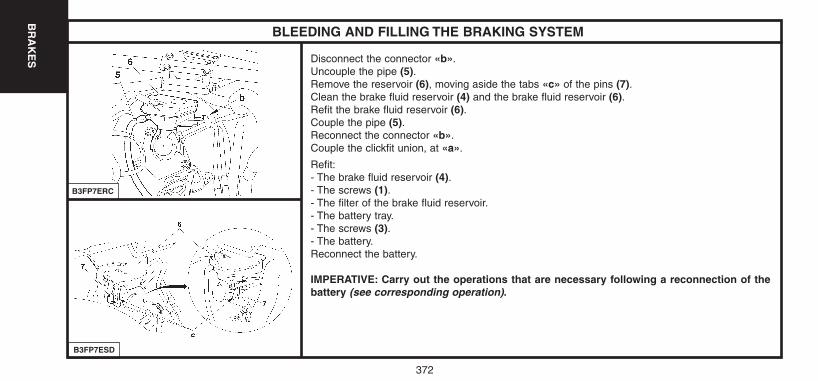
372
BR
AK
ES
B3FP7ESD
BLEEDING AND FILLING THE BRAKING SYSTEM
Disconnect the connector «b».Uncouple the pipe (5).Remove the reservoir (6), moving aside the tabs «c» of the pins (7).Clean the brake fluid reservoir (4) and the brake fluid reservoir (6).Refit the brake fluid reservoir (6).Couple the pipe (5).Reconnect the connector «b».Couple the clickfit union, at «a».
Refit:- The brake fluid reservoir (4).- The screws (1).- The filter of the brake fluid reservoir.- The battery tray.- The screws (3).- The battery.Reconnect the battery.
IMPERATIVE: Carry out the operations that are necessary following a reconnection of thebattery (see corresponding operation).
B3FP7ERC
UK-C4-PAGE361-375-2004 15/11/04 9:09 Page 372
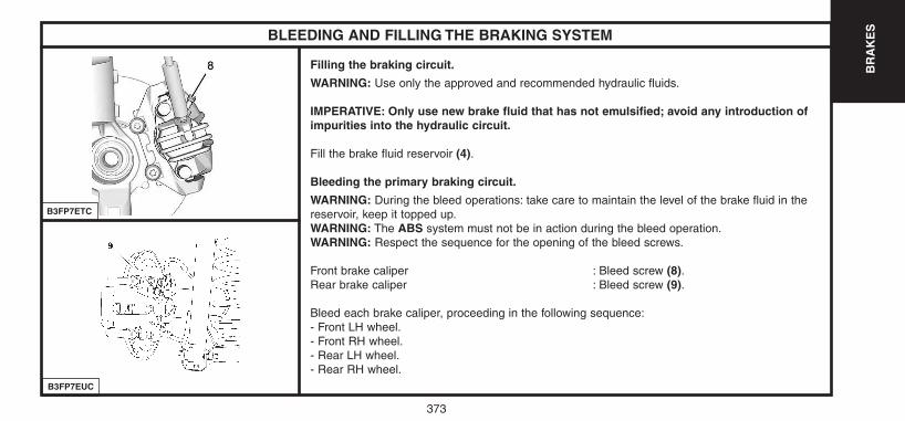
373
BR
AK
ES
B3FP7EUC
BLEEDING AND FILLING THE BRAKING SYSTEM
Filling the braking circuit.
WARNING: Use only the approved and recommended hydraulic fluids.
IMPERATIVE: Only use new brake fluid that has not emulsified; avoid any introduction ofimpurities into the hydraulic circuit.
Fill the brake fluid reservoir (4).
Bleeding the primary braking circuit.
WARNING: During the bleed operations: take care to maintain the level of the brake fluid in thereservoir, keep it topped up.WARNING: The ABS system must not be in action during the bleed operation.WARNING: Respect the sequence for the opening of the bleed screws.
Front brake caliper : Bleed screw (8).Rear brake caliper : Bleed screw (9).
Bleed each brake caliper, proceeding in the following sequence:- Front LH wheel.- Front RH wheel.- Rear LH wheel.- Rear RH wheel.
B3FP7ETC
UK-C4-PAGE361-375-2004 15/11/04 9:09 Page 373
374
BR
AK
ES
BLEEDING AND FILLING THE BRAKING SYSTEM
Bleeding the braking circuit with the bleed apparatus.
Connect the bleed apparatus [1] on the brake fluid reservoir (4).
Adjust the apparatus pressure to 2 Bars.
For each brake circuit:- Couple a transparent tube on the bleed screw.- Submerge the other end of the tube in a clean container.- Open the bleed screw.- Wait until the brake fluid flows out without air bubbles.- Close the bleed screw.- Remove the bleed apparatus [1].
Check the level of the brake fluid (between the «DANGER» level and the «MAXI» level).
Fill if necessary with the the approved and recommended synthetic brake fluid.
UK-C4-PAGE361-375-2004 15/11/04 9:09 Page 374
375
BR
AK
ESBLEEDING AND FILLING THE BRAKING SYSTEM
Bleeding the braking circuit without the bleed apparatus.
NOTE: Two operators are necessary.
For each brake circuit:
- Apply the brake pedal to place the circuit under pressure.- Couple a transparent tube on the bleed screw.- Submerge the other end of the tube in a clean container.- Open the bleed screw.- Wait until the fluid flows out without air bubbles.- Close the bleed screw.
NOTE: Recommence the process a second time if that is necessary.
Check the level of the brake fluid (between the «DANGER» level andthe «MAXI» level).
Fill if necessary with the the approved and recommended syntheticbrake fluid.
Bleeding the secondary braking circuit.
WARNING: During the bleed operations: take care to maintain the levelof the brake fluid in the reservoir, keep it topped up.
NOTE: The bleed apparatus [1] is still connected on the brake fluidreservoir (4).
Use the diagnostic tools [2] or [3].
Select the menu corresponding to the vehicle:- ABS menu (according to equipment).- ESP menu (according to equipment).
Follow the instructions of the diagnostic tool.
At the end of the bleed programme, check the level of the brake fluid,top up if necessary.
Check the travel of the brake pedal: it must not be excessive. If it is,restart the bleed procedure.
UK-C4-PAGE361-375-2004 15/11/04 9:09 Page 375
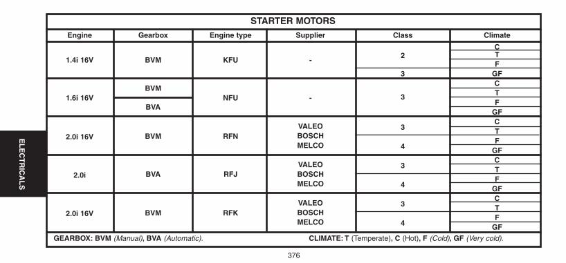
Engine Gearbox Engine type Supplier Class Climate
C
1.4i 16V BVM KFU -2 T
F3 GF
CBVM
T1.6i 16V
BVANFU - 3
FGF
VALEO 3C
2.0i 16V BOSCHT
BVM RFNMELCO 4
FGF
VALEO 3C
2.0i BVA RFJ BOSCHT
MELCO 4F
GF
VALEO 3C
2.0i 16V BOSCHT
BVM RFKMELCO 4
FGF
GEARBOX: BVM (Manual), BVA (Automatic). CLIMATE: T (Temperate), C (Hot), F (Cold), GF (Very cold).
STARTER MOTORS
376
EL
EC
TR
ICA
LS
UK-C4-page376-384-2004 15/11/04 9:11 Page 376
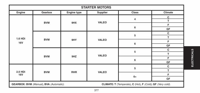
EL
EC
TR
ICA
LS
377
Engine Gearbox Engine type Supplier Class Climate
C
BVM 9HX VALEO4
T
F6
GF
C
BVM
5T1.6 HDi 9HY VALEOF16V 6
GF
5C
VALEOT
BVM 9HZ6
F
GF
5C
2.0 HDi BVM RHR VALEOT
16V6+
F
GF
GEARBOX: BVM (Manual), BVA (Automatic). CLIMATE: T (Temperate), C (Hot), F (Cold), GF (Very cold).
STARTER MOTORS
UK-C4-page376-384-2004 15/11/04 9:11 Page 377
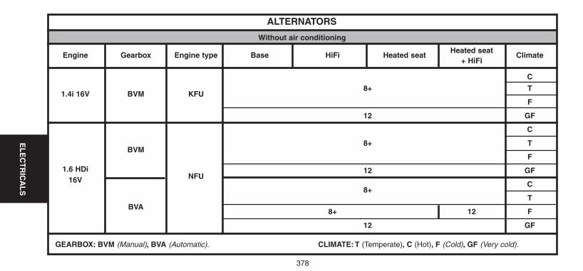
EL
EC
TR
ICA
LS
378
Engine Gearbox Engine type Base HiFi Heated seat Heated seat
Climate+ HiFi
C
1.4i 16V BVM KFU8+ T
F
12 GF
C
BVM8+ T
1.6 HDi
F
16V NFU12 GF
8+C
TBVA
8+ 12 F
12 GF
GEARBOX: BVM (Manual), BVA (Automatic). CLIMATE: T (Temperate), C (Hot), F (Cold), GF (Very cold).
ALTERNATORS
Without air conditioning
UK-C4-page376-384-2004 15/11/04 9:11 Page 378
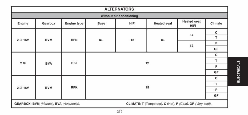
379
EL
EC
TR
ICA
LS
Engine Gearbox Engine type Base HiFi Heated seatHeated seat
Climate+ HiFi
8+C
2.0i 16V BVM RFN 8+ 12 8+T
12F
GF
C
2.0i BVA RFJ 12T
F
GF
C
T2.0i 16V BVM RFK 15
F
GF
GEARBOX: BVM (Manual), BVA (Automatic). CLIMATE: T (Temperate), C (Hot), F (Cold), GF (Very cold).
ALTERNATORS
Without air conditioning
UK-C4-page376-384-2004 15/11/04 9:11 Page 379
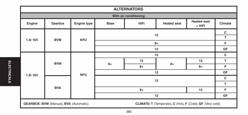
380
EL
EC
TR
ICA
LS
Engine Gearbox Engine type Base HiFi Heated seat Heated seat
Climate+ HiFi
C
1.4i 16V BVM KFU
12T
8+ F
12 GF
12 C
BVM 8+12
8+12 T
8+ 8+ F
1.6i 16V NFU12 GF
12C
TBVA
8+ 12 F
12 GF
GEARBOX: BVM (Manual), BVA (Automatic). CLIMATE: T (Temperate), C (Hot), F (Cold), GF (Very cold).
ALTERNATORS
With air conditioning
UK-C4-page376-384-2004 15/11/04 9:11 Page 380
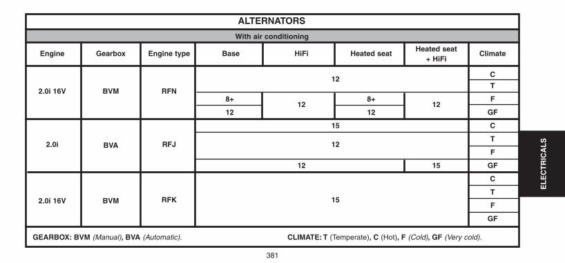
381
EL
EC
TR
ICA
LS
Engine Gearbox Engine type Base HiFi Heated seatHeated seat
Climate+ HiFi
12C
2.0i 16V BVM RFNT
8+12
8+12
F
12 12 GF
15 C
2.0i BVA RFJ 12T
F
12 15 GF
C
T2.0i 16V BVM RFK 15
F
GF
GEARBOX: BVM (Manual), BVA (Automatic). CLIMATE: T (Temperate), C (Hot), F (Cold), GF (Very cold).
ALTERNATORS
With air conditioning
UK-C4-page376-384-2004 15/11/04 9:11 Page 381
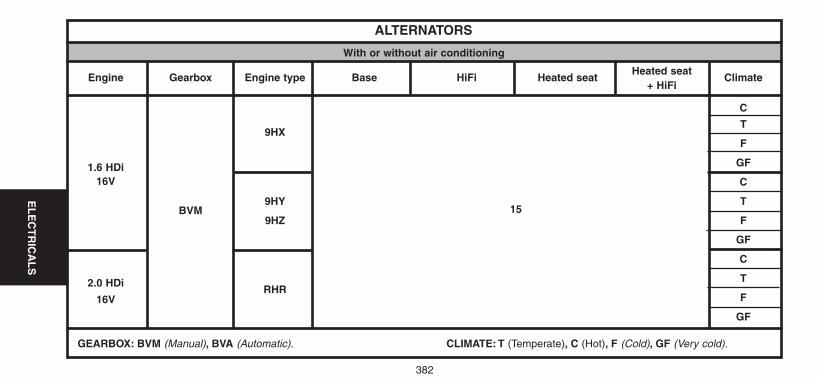
382
EL
EC
TR
ICA
LS
Engine Gearbox Engine type Base HiFi Heated seat Heated seat
Climate+ HiFi
C
9HXT
F
GF1.6 HDiC16V
BVM9HY
15T
9HZ F
GF
C
T2.0 HDi RHR
F16V
GF
GEARBOX: BVM (Manual), BVA (Automatic). CLIMATE: T (Temperate), C (Hot), F (Cold), GF (Very cold).
ALTERNATORS
With or without air conditioning
UK-C4-page376-384-2004 15/11/04 9:11 Page 382
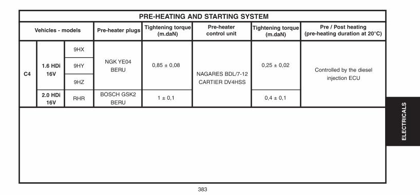
EL
EC
TR
ICA
LS
383
9HX
1.6 HDi 9HYNGK YE04
0,85 ± 0,08 0,25 ± 0,02
C4 16VBERU Controlled by the diesel
9HZ
NAGARES BDL/7-12injection ECU
CARTIER DV4HSS
2.0 HDiRHR
BOSCH GSK21 ± 0,1 0,4 ± 0,1
16V BERU
Vehicles - models Pre-heater plugsPre-heater
control unitPre / Post heating
(pre-heating duration at 20°C)
PRE-HEATING AND STARTING SYSTEM
Tightening torque(m.daN)
Tightening torque(m.daN)
UK-C4-page376-384-2004 15/11/04 9:11 Page 383
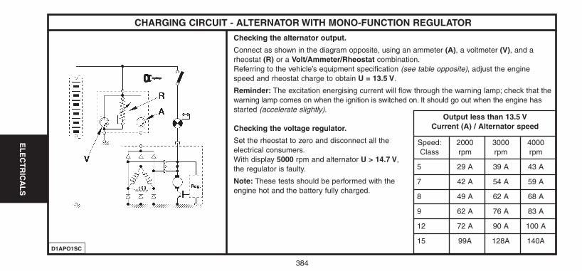
CHARGING CIRCUIT - ALTERNATOR WITH MONO-FUNCTION REGULATOR
384
EL
EC
TR
ICA
LS
Checking the alternator output.
Connect as shown in the diagram opposite, using an ammeter (A), a voltmeter (V), and arheostat (R) or a Volt/Ammeter/Rheostat combination.Referring to the vehicle’s equipment specification (see table opposite), adjust the enginespeed and rheostat charge to obtain U = 13.5 V.
Reminder: The excitation energising current will flow through the warning lamp; check that thewarning lamp comes on when the ignition is switched on. It should go out when the engine hasstarted (accelerate slightly).
Checking the voltage regulator.
Set the rheostat to zero and disconnect all the electrical consumers.With display 5000 rpm and alternator U > 14.7 V,the regulator is faulty.
Note: These tests should be performed with theengine hot and the battery fully charged.
D1APO1SC
Output less than 13.5 VCurrent (A) / Alternator speed
Speed: 2000 3000 4000Class rpm rpm rpm
5 29 A 39 A 43 A
7 42 A 54 A 59 A
8 49 A 62 A 68 A
9 62 A 76 A 83 A
12 72 A 90 A 100 A
15 99A 128A 140A
UK-C4-page376-384-2004 15/11/04 9:11 Page 384
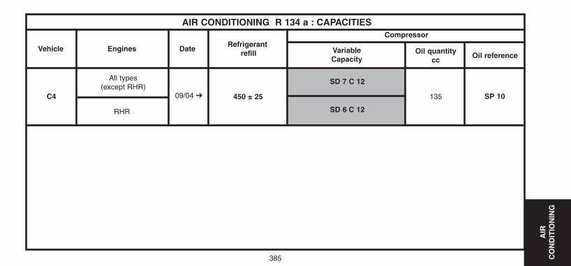
385
AIR
C
ON
DIT
ION
ING
SP 10
AIR CONDITIONING R 134 a : CAPACITIES
Vehicle
C4
SD 7 C 12
SD 6 C 12
135450 ± 2509/04 ➔
All types(except RHR)
RHR
Engines DateRefrigerant
refill
Compressor
VariableCapacity
Oil quantitycc
Oil reference
UK-C4-page385-409-2004 15/11/04 9:13 Page 385
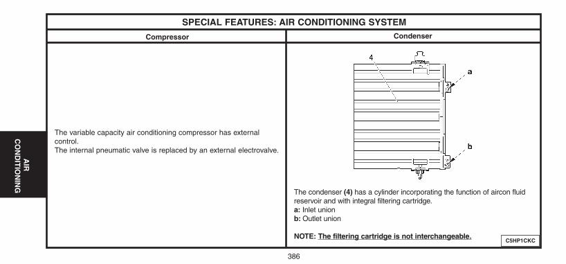
C5HP1CKC
CondenserCompressor
The variable capacity air conditioning compressor has externalcontrol.The internal pneumatic valve is replaced by an external electrovalve.
The condenser (4) has a cylinder incorporating the function of aircon fluidreservoir and with integral filtering cartridge.a: Inlet unionb: Outlet union
NOTE: The filtering cartridge is not interchangeable.
SPECIAL FEATURES: AIR CONDITIONING SYSTEM
386
AIR
CO
ND
ITIO
NIN
G
UK-C4-page385-409-2004 15/11/04 9:13 Page 386
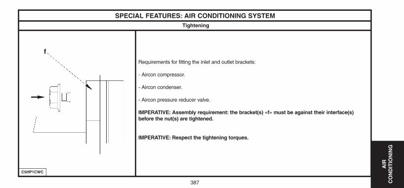
387
AIR
C
ON
DIT
ION
ING
C5HP1CWC
Tightening
Requirements for fitting the inlet and outlet brackets:
- Aircon compressor.
- Aircon condenser.
- Aircon pressure reducer valve.
IMPERATIVE: Assembly requirement: the bracket(s) «f» must be against their interface(s)before the nut(s) are tightened.
IMPERATIVE: Respect the tightening torques.
SPECIAL FEATURES: AIR CONDITIONING SYSTEM
UK-C4-page385-409-2004 15/11/04 9:13 Page 387
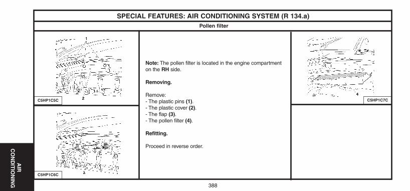
388
AIR
CO
ND
ITIO
NIN
G
C5HP1C6C
Pollen filter
Note: The pollen filter is located in the engine compartmenton the RH side.
Removing.
Remove:- The plastic pins (1).- The plastic cover (2).- The flap (3).- The pollen filter (4).
Refitting.
Proceed in reverse order.
SPECIAL FEATURES: AIR CONDITIONING SYSTEM (R 134.a)
C5HP1C5C C5HP1C7C
UK-C4-page385-409-2004 15/11/04 9:13 Page 388
389
AIR
C
ON
DIT
ION
ING
ESSENTIAL: The compressor lubricant is extremely hygroscopic; always use FRESH oil.
Checking the compressor oil level
There are three specific cases:- 1/ Repairs to a system without leaks.- 2/ Slow leak.- 3/ Fast leak.
1/ Repairing a system without leaks.
a) - Using draining/recovery equipment not fitted with an oil decanter.- Drain the system as slowly as possible via the LOW PRESSURE valve, so as not to lose any oil.- No more oil should be added when filling the system with R 134.a fluid.
b) - Using draining/filling equipment fitted with an oil decanter.- Drain the R 134.a fluid from the system in accordance with the instructions in the equipment handbook.- Measure the amount of oil recovered.- Add the same amount of NEW oil when filling the system with R 134.a fluid.
c) - Replacing a compressor.- Remove the old compressor, drain it and measure the oil quantity.- Drain the new compressor (supplied full), so that the same amount of NEW oil is left in the compressor as was in the old compressor.- No more oil should be added when filling the system with R 134.a fluid.
SPECIAL FEATURES: AIR CONDITIONING SYSTEM (R 134.a)Compressor lubricant
UK-C4-page385-409-2004 15/11/04 9:13 Page 389
AIR
CO
ND
ITIO
NIN
G
390
Checking the compressor oil level (continued)
2/ Slow leak.
- Slow leaks do not lead to oil loss, therefore the same procedure should be followed as if there was no leak at all.
3/ Fast leak.
This type of leak causes both oil loss as well as allowing air to enter the system.
It is therefore necessary to:
- Replace the dehydrator.
- Drain as much oil as possible (when replacing the faulty component).
Either before or during filling of the system with R 134.a fluid, introduce 80 cc of NEW oil into the system.
SPECIAL FEATURES: AIR CONDITIONING SYSTEM (R 134.a)
UK-C4-page385-409-2004 15/11/04 9:13 Page 390
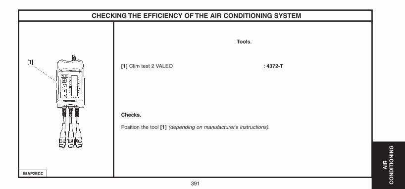
AIR
C
ON
DIT
ION
ING
391
Tools.
[1] Clim test 2 VALEO : 4372-T
Checks.
Position the tool [1] (depending on manufacturer’s instructions).
CHECKING THE EFFICIENCY OF THE AIR CONDITIONING SYSTEM
E5AP2ECC
UK-C4-page385-409-2004 15/11/04 9:13 Page 391
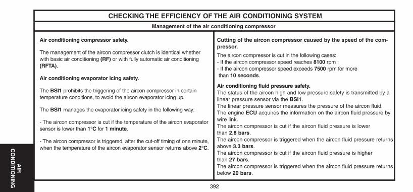
AIR
C
ON
DIT
ION
ING
392
Management of the air conditioning compressor
CHECKING THE EFFICIENCY OF THE AIR CONDITIONING SYSTEM
Air conditioning compressor safety.
The management of the aircon compressor clutch is identical whetherwith basic air conditioning (RF) or with fully automatic air conditioning(RFTA).
Air conditioning evaporator icing safety.
The BSI1 prohibits the triggering of the aircon compressor in certain temperature conditions, to avoid the aircon evaporator icing up.
The BSI1 manages the evaporator icing safety in the following way:
- The aircon compressor is cut if the temperature of the aircon evaporatorsensor is lower than 1°C for 1 minute.
- The aircon compressor is triggered, after the cut-off timing of one minute,when the temperature of the aircon evaporator sensor returns above 2°C.
Cutting of the aircon compressor caused by the speed of the com-pressor.
The aircon compressor is cut in the following cases:- If the aircon compressor speed reaches 8100 rpm ;- If the aircon compressor speed exceeds 7500 rpm for morethan 10 seconds.
Air conditioning fluid pressure safety.The status of the aircon high and low pressure safety is transmitted by alinear pressure sensor via the BSI1.The linear pressure sensor measures the pressure of the aircon fluid.The engine ECU acquires the information on the aircon fluid pressure bywire link.The aircon compressor is cut if the aircon fluid pressure is lowerthan 2.8 bars.The aircon compressor is triggered when the aircon fluid pressure returnsabove 3.3 bars.The aircon compressor is cut if the aircon fluid pressure is higherthan 27 bars.The aircon compressor is triggered when the aircon fluid pressure returnsbelow 20 bars.
UK-C4-page385-409-2004 15/11/04 9:13 Page 392
AIR
C
ON
DIT
ION
ING
393
Management of the air conditioning compressor
Safety as a function of the outside temperature.
The aircon compressor is cut if the outside temperature is lower than 3.5 °C.The aircon compressor is triggered when the outside temperature goes above 5°C.
Safety as a function of electric diagnosis.
The cutting of the aircon compressor is effective in the following conditions:- Fault in the aircon compressor clutch.- Fault in the aircon compressor electrovanne.- Fault in the aircon fluid pressure sensor.- Fault in the blower (delay of 30 seconds).- Fault in communication between the engine ECU and the BSI1.- Fault in communication between the engine relay unit (BSM) and the BSI1.
NOTE: see procedure «Principle of operation: air conditioning».
CHECKING THE EFFICIENCY OF THE AIR CONDITIONING SYSTEM
UK-C4-page385-409-2004 15/11/04 9:13 Page 393
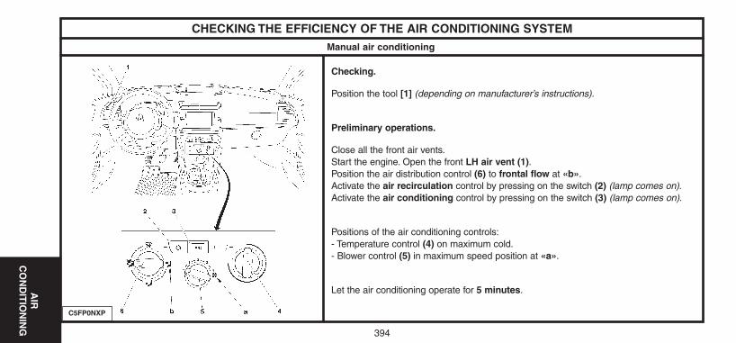
394
AIR
C
ON
DIT
ION
ING
Manual air conditioning
Checking.
Position the tool [1] (depending on manufacturer’s instructions).
Preliminary operations.
Close all the front air vents.Start the engine. Open the front LH air vent (1).Position the air distribution control (6) to frontal flow at «b».Activate the air recirculation control by pressing on the switch (2) (lamp comes on).Activate the air conditioning control by pressing on the switch (3) (lamp comes on).
Positions of the air conditioning controls:- Temperature control (4) on maximum cold.- Blower control (5) in maximum speed position at «a».
Let the air conditioning operate for 5 minutes.
CHECKING THE EFFICIENCY OF THE AIR CONDITIONING SYSTEM
C5FP0NXP
UK-C4-page385-409-2004 15/11/04 9:13 Page 394
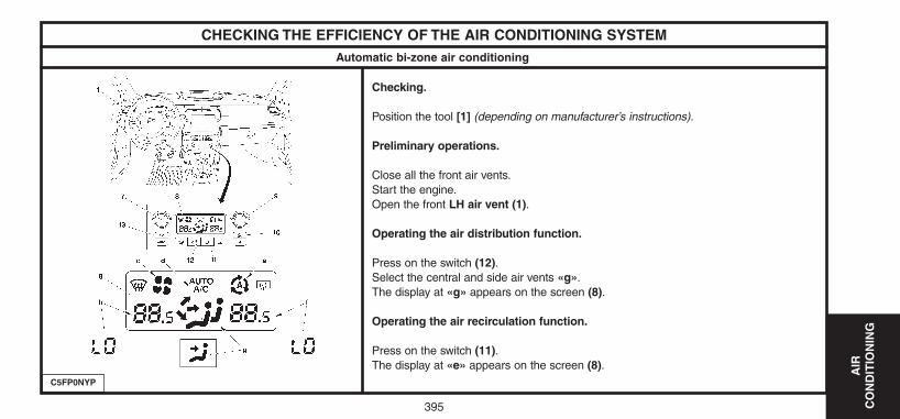
395
AIR
C
ON
DIT
ION
ING
Automatic bi-zone air conditioning
Checking.
Position the tool [1] (depending on manufacturer’s instructions).
Preliminary operations.
Close all the front air vents.Start the engine.Open the front LH air vent (1).
Operating the air distribution function.
Press on the switch (12).Select the central and side air vents «g».The display at «g» appears on the screen (8).
Operating the air recirculation function.
Press on the switch (11).The display at «e» appears on the screen (8).
CHECKING THE EFFICIENCY OF THE AIR CONDITIONING SYSTEM
C5FP0NYP
UK-C4-page385-409-2004 15/11/04 9:13 Page 395
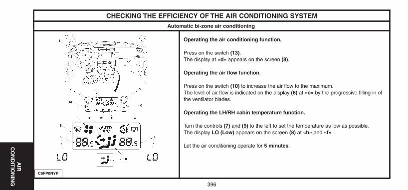
AIR
C
ON
DIT
ION
ING
396
Automatic bi-zone air conditioning
Operating the air conditioning function.
Press on the switch (13).The display at «d» appears on the screen (8).
Operating the air flow function.
Press on the switch (10) to increase the air flow to the maximum.The level of air flow is indicated on the display (8) at «c» by the progressive filling-in ofthe ventilator blades.
Operating the LH/RH cabin temperature function.
Turn the controls (7) and (9) to the left to set the temperature as low as possible.The display LO (Low) appears on the screen (8) at «h» and «f».
Let the air conditioning operate for 5 minutes.
CHECKING THE EFFICIENCY OF THE AIR CONDITIONING SYSTEM
C5FP0NYP
UK-C4-page385-409-2004 15/11/04 9:13 Page 396
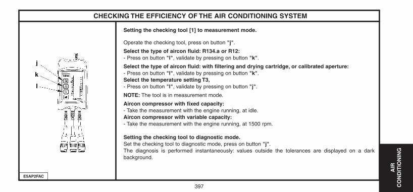
AIR
C
ON
DIT
ION
ING
397
Setting the checking tool [1] to measurement mode.
Operate the checking tool, press on button "j".
Select the type of aircon fluid: R134.a or R12:- Press on button "l", validate by pressing on button "k".
Select the type of aircon fluid: with filtering and drying cartridge, or calibrated aperture:- Press on button "l", validate by pressing on button "k".Select the temperature setting T3,- Press on button "l", validate by pressing on button "j".
NOTE: The tool is in measurement mode.
Aircon compressor with fixed capacity:- Take the measurement with the engine running, at idle.Aircon compressor with variable capacity:- Take the measurement with the engine running, at 1500 rpm.
Setting the checking tool to diagnostic mode.Set the checking tool to diagnostic mode, press on button "j".The diagnosis is performed instantaneously: values outside the tolerances are displayed on a dark background.
CHECKING THE EFFICIENCY OF THE AIR CONDITIONING SYSTEM
E5AP2FAC
UK-C4-page385-409-2004 15/11/04 9:13 Page 397
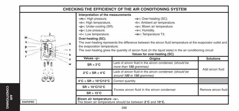
AIR
C
ON
DIT
ION
ING
398
Interpretation of the measurements«m»: High pressure. «s»: Over-heating (SC).«n»: High temperature. «t»: Ambient air temperature.«p»: Under-cooling (SR). «u»: Blown air temperature.«q»: Low pressure. «v»: Humidity.«r»: Low temperature. «w»: Temperature T3.Over-heating (SC).The over-heating represents the difference between the aircon fluid temperature at the evaporator outlet andthe evaporation temperature.The over-heating gives the quantity of aircon fluid (in the liquid state) in the air conditioning circuit
Values for over-heating (SC)
CHECKING THE EFFICIENCY OF THE AIR CONDITIONING SYSTEM
E5AP2FBC
Values «p» Origins Solutions
SR < 2°C
2°C < SR < 4°C
Lack of aircon fluid in the aircon condenser (should bemore than 150 grammes)
Lack of aircon fluid in the aircon condenser (should bearound 100 to 150 grammes)
4°C < SR < 10°C/12°C Correct quantity
SR > 10°C/12°CExcess aircon fluid in the aircon condenser
SR > 15°C
Add aircon fluid
Remove aircon fluid
Blown air temperature «u».The blown air temperature should be between 2°C and 10°C.
UK-C4-page385-409-2004 15/11/04 9:13 Page 398
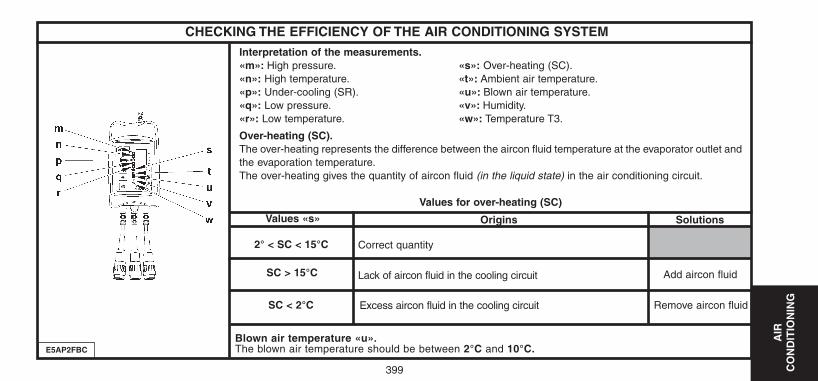
AIR
C
ON
DIT
ION
ING
399
Interpretation of the measurements.«m»: High pressure. «s»: Over-heating (SC).«n»: High temperature. «t»: Ambient air temperature.«p»: Under-cooling (SR). «u»: Blown air temperature.«q»: Low pressure. «v»: Humidity.«r»: Low temperature. «w»: Temperature T3.
Over-heating (SC).The over-heating represents the difference between the aircon fluid temperature at the evaporator outlet andthe evaporation temperature.The over-heating gives the quantity of aircon fluid (in the liquid state) in the air conditioning circuit.
Values for over-heating (SC)
CHECKING THE EFFICIENCY OF THE AIR CONDITIONING SYSTEM
E5AP2FBC
Values «s» Origins Solutions
2° < SC < 15°C
SC > 15°C
Correct quantity
Lack of aircon fluid in the cooling circuit
SC < 2°C Excess aircon fluid in the cooling circuit
Add aircon fluid
Remove aircon fluid
Blown air temperature «u».The blown air temperature should be between 2°C and 10°C.
UK-C4-page385-409-2004 15/11/04 9:13 Page 399
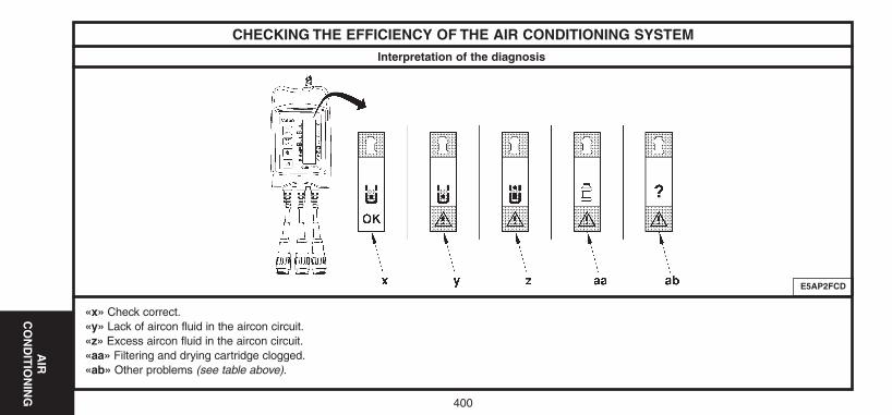
400
AIR
C
ON
DIT
ION
ING
Interpretation of the diagnosis
«x» Check correct.«y» Lack of aircon fluid in the aircon circuit.«z» Excess aircon fluid in the aircon circuit.«aa» Filtering and drying cartridge clogged.«ab» Other problems (see table above).
CHECKING THE EFFICIENCY OF THE AIR CONDITIONING SYSTEM
E5AP2FCD
UK-C4-page385-409-2004 15/11/04 9:13 Page 400
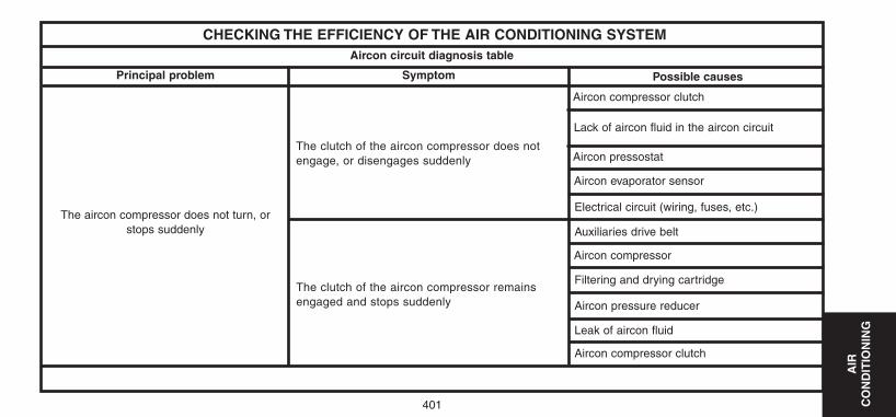
401
AIR
C
ON
DIT
ION
ING
CHECKING THE EFFICIENCY OF THE AIR CONDITIONING SYSTEM
Principal problem Symptom Possible causes
The aircon compressor does not turn, orstops suddenly
Aircon compressor clutch
The clutch of the aircon compressor does notengage, or disengages suddenly
The clutch of the aircon compressor remainsengaged and stops suddenly
Aircon circuit diagnosis table
Lack of aircon fluid in the aircon circuit
Aircon pressostat
Aircon evaporator sensor
Electrical circuit (wiring, fuses, etc.)
Auxiliaries drive belt
Aircon compressor
Filtering and drying cartridge
Aircon pressure reducer
Leak of aircon fluid
Aircon compressor clutch
UK-C4-page385-409-2004 15/11/04 9:13 Page 401
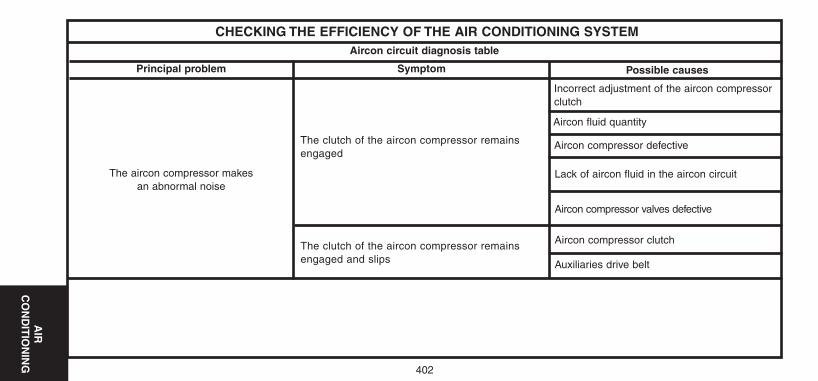
402
AIR
C
ON
DIT
ION
ING
CHECKING THE EFFICIENCY OF THE AIR CONDITIONING SYSTEM
Principal problem Symptom Possible causes
The aircon compressor makes an abnormal noise
The clutch of the aircon compressor remainsengaged
The clutch of the aircon compressor remainsengaged and slips
Aircon circuit diagnosis table
Incorrect adjustment of the aircon compressorclutch
Aircon fluid quantity
Aircon compressor defective
Lack of aircon fluid in the aircon circuit
Aircon compressor valves defective
Aircon compressor clutch
Auxiliaries drive belt
UK-C4-page385-409-2004 15/11/04 9:13 Page 402
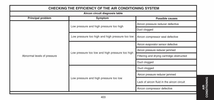
403
AIR
C
ON
DIT
ION
ING
CHECKING THE EFFICIENCY OF THE AIR CONDITIONING SYSTEM
Principal problem Symptom Possible causes
Abnormal levels of pressure
Low pressure and high pressure too high
Low pressure and high pressure too low
Aircon circuit diagnosis table
Aircon pressure reducer defective
Duct clogged
Aircon compressor seal defective
Aircon evaporator sensor defective
Filtering and drying cartridge obstructed
Lack of aircon fluid in the aircon circuit
Aircon compressor defective
Low pressure too high and high pressure too low
Low pressure too low and high pressure too highAircon pressure reducer jammed
Duct clogged
Duct clogged
Aircon pressure reducer jammed
UK-C4-page385-409-2004 15/11/04 9:13 Page 403
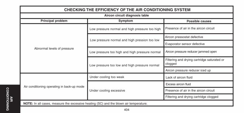
404
AIR
C
ON
DIT
ION
ING
CHECKING THE EFFICIENCY OF THE AIR CONDITIONING SYSTEM
Principal problem Symptom Possible causes
Abnormal levels of pressure
Low pressure normal and high pressure too high
Under cooling too weak
Aircon circuit diagnosis table
Presence of air in the aircon circuit
Aircon pressostat defective
Evaporator sensor defective
Aircon pressure reducer jammed open
Filtering and drying cartridge saturated orclogged
Presence of air in the aircon circuit
Filtering and drying cartridge clogged
Low pressure normal and high pression too low
Low pressure too high and high pressure normal
Aircon pressure reducer iced up
Lack of aircon fluid
Excess aircon fluid
Low pressure too low and high pressure normal
Air conditioning operating in back-up modeUnder cooling excessive
NOTE: In all cases, measure the excessive heating (SC) and the blown air temperature.
UK-C4-page385-409-2004 15/11/04 9:13 Page 404
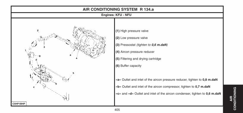
405
AIR
C
ON
DIT
ION
ING
(1) High pressure valve
(2) Low pressure valve
(3) Pressostat (tighten to 0,6 m.daN)
(4) Aircon pressure reducer
(5) Filtering and drying cartridge
(6) Buffer capacity
«a» Outlet and inlet of the aircon pressure reducer, tighten to 0,8 m.daN
«b» Outlet and inlet of the aircon compressor, tighten to 0,7 m.daN
«c» and «d» Outlet and inlet of the aircon condenser, tighten to 0,6 m.daN
AIR CONDITIONING SYSTEM R 134.a
C5HP1BHP
Engines: KFU - NFU
UK-C4-page385-409-2004 15/11/04 9:13 Page 405
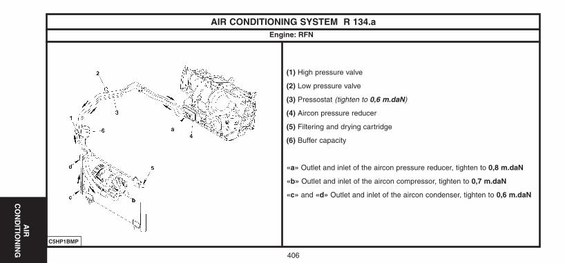
AIR
C
ON
DIT
ION
ING
406
(1) High pressure valve
(2) Low pressure valve
(3) Pressostat (tighten to 0,6 m.daN)
(4) Aircon pressure reducer
(5) Filtering and drying cartridge
(6) Buffer capacity
«a» Outlet and inlet of the aircon pressure reducer, tighten to 0,8 m.daN
«b» Outlet and inlet of the aircon compressor, tighten to 0,7 m.daN
«c» and «d» Outlet and inlet of the aircon condenser, tighten to 0,6 m.daN
C5HP1BMP
AIR CONDITIONING SYSTEM R 134.aEngine: RFN
UK-C4-page385-409-2004 15/11/04 9:13 Page 406
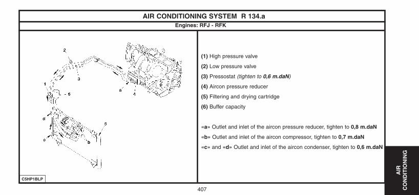
AIR
C
ON
DIT
ION
ING
407
(1) High pressure valve
(2) Low pressure valve
(3) Pressostat (tighten to 0,6 m.daN)
(4) Aircon pressure reducer
(5) Filtering and drying cartridge
(6) Buffer capacity
«a» Outlet and inlet of the aircon pressure reducer, tighten to 0,8 m.daN
«b» Outlet and inlet of the aircon compressor, tighten to 0,7 m.daN
«c» and «d» Outlet and inlet of the aircon condenser, tighten to 0,6 m.daN
AIR CONDITIONING SYSTEM R 134.a
C5HP1BLP
Engines: RFJ - RFK
UK-C4-page385-409-2004 15/11/04 9:13 Page 407

AIR
C
ON
DIT
ION
ING
408
(1) High pressure valve
(2) Low pressure valve
(3) Pressostat (tighten to 0,6 m.daN)
(4) Aircon pressure reducer
(5) Filtering and drying cartridge
(6) Buffer capacity
«a» Outlet and inlet of the aircon pressure reducer, tighten to 0,8 m.daN
«b» Outlet and inlet of the aircon compressor, tighten to 0,7 m.daN
«c» and «d» Outlet and inlet of the aircon condenser, tighten to 0,6 m.daN
C5HP1BNP
AIR CONDITIONING SYSTEM R 134.aEngines: 9HX - 9HY - 9HZ
UK-C4-page385-409-2004 15/11/04 9:13 Page 408
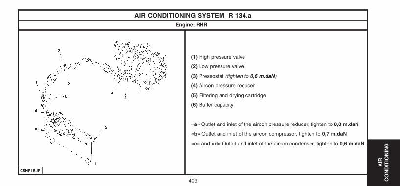
AIR
C
ON
DIT
ION
ING
409
(1) High pressure valve
(2) Low pressure valve
(3) Pressostat (tighten to 0,6 m.daN)
(4) Aircon pressure reducer
(5) Filtering and drying cartridge
(6) Buffer capacity
«a» Outlet and inlet of the aircon pressure reducer, tighten to 0,8 m.daN
«b» Outlet and inlet of the aircon compressor, tighten to 0,7 m.daN
«c» and «d» Outlet and inlet of the aircon condenser, tighten to 0,6 m.daN
C5HP1BJP
AIR CONDITIONING SYSTEM R 134.aEngine: RHR
UK-C4-page385-409-2004 15/11/04 9:13 Page 409
Related Documents