Camera Link Specifications of the Camera Link Interface Standard for Digital Cameras and Frame Grabbers Camera Link Specifications October 2000

Welcome message from author
This document is posted to help you gain knowledge. Please leave a comment to let me know what you think about it! Share it to your friends and learn new things together.
Transcript
Camera Link
Specifications of the Camera Link Interface Standard for Digital Cameras and Frame GrabbersCamera Link Specifications
October 2000

ii Camera Link Specifications
Acknowledgements
Participating CompaniesThe following companies contributed to the development and definition of the Camera Link standard.
• Basler
• Cognex
• Coreco
• DALSA
• Data Translation
• Datacube
• EPIX
• Euresys
• Foresight Imaging
• Integral Technologies
• Matrox
• National Instruments
• PULNiX America
Rights and TrademarksPULNiX America, Inc., as chair of this ad hoc Camera Link committee, has applied for U.S. trademark protection for the term "Camera Link" to secure it for the mutual benefit of industry members. PULNiX will issue a perpetual royalty-free license to any industry member (including competitors) for the use of the "Camera Link" trademark on the condition that it is used only in conjunction with products that are fully compliant to this standard. PULNiX will not require licensed users of the trademark to credit PULNiX with ownership.
3M™ is a trademark of the 3M Company.
Channel Link™ is a trademark of National Semiconductor.
Flatlink™ is a trademark of Texas Instruments.
Panel Link™ is a trademark of Silicon Image.
About this Document
The following specifications provide a framework for Camera Link communication. The specifications are deliberately defined to be open, allowing camera and frame grabber manufacturers to differentiate their products. Additional recommendations may be added at a later date, which will not affect the accuracy of the information in this document.
iii Camera Link Specifications
Contents
AcknowledgementsParticipating Companies ................................................................................................ iiRights and Trademarks .................................................................................................. ii
About this Document
Chapter 1Camera Link
Introduction....................................................................................................................1-1LVDS Technical Description.........................................................................................1-1Channel Link..................................................................................................................1-2Technology Benefits ......................................................................................................1-3
Smaller Connectors and Cables.......................................................................1-3High Data Transmission Rates ........................................................................1-3
Chapter 2Camera Signal Requirements
Video Data.......................................................................................................2-1Camera Control Signals...................................................................................2-1Communication ...............................................................................................2-2Power...............................................................................................................2-2
Chapter 3Port Assignments
Port Definition .................................................................................................3-1
Chapter 4Bit Assignments
Chapter 5Camera Link Connections
MDR 26-pin Connector...................................................................................5-1Camera Link Cable Pinout ..............................................................................5-2Shielding Recommendations ...........................................................................5-3
iv Camera Link Specifications
Contents
Appendix AChipset Criteria
Appendix BAPI Functions
Appendix CBit Assignments According to Configuration
Appendix DCamera Link Cabling Information
FiguresFigure 1-1. Channel Link Operation........................................................................ 1-2
Figure 3-1. Data Routing for Base, Medium, and Full Configurations ................... 3-2Figure 3-2. Block Diagram of Base, Medium, and Full Configuration .................. 3-3
Figure 5-1. Camera Link Cable ............................................................................... 5-1
Figure D-1. Dimensions of 3M Connector ............................................................... D-1Figure D-2. 3M Part Number Ordering Information ................................................ D-3
TablesTable 3-1. Port Assignments According to Configuration..................................... 3-1
Table 4-1. Camera Link Bit Assignment................................................................ 4-1
Table A-1. Compatible National Semiconductor Parts ........................................... A-1
Table C-1. Bit Assignments for Base Configuration .............................................. C-1Table C-2. Bit Assignment for Medium Configuration .......................................... C-2Table C-3. Bit Assignment for Full Configuration ................................................. C-4
Table D-1. Shell Options......................................................................................... D-3Table D-2. 3M Boardmount Receptacle Part Numbers .......................................... D-4
Camera Link Specifications v
1-1 Camera L
1
Camera LinkIntroductionCamera Link is a communication interface for vision applications. The interface extends the base technology of Channel Link to provide a specification more useful for vision applications.
For years, the scientific and industrial digital video market has lacked a standard method of communication. Both frame grabbers and camera manufacturers developed products with different connectors, making cable production difficult for manufacturers and very confusing for consumers. A connectivity standard between digital cameras and frame grabbers is long overdue and will become even more necessary as data rates continue to increase.
Increasingly diverse cameras and advanced signal and data transmissions have made a connectivity standard like Camera Link a necessity. The Camera Link interface will reduce support time, as well as the cost of that support. The standard cable will be able to handle the increased signal speeds, and the cable assembly will allow customers to reduce their costs through volume pricing.
LVDS Technical DescriptionLow Voltage Differential Signaling (LVDS) is a high-speed, low-power general purpose interface standard. The standard, known as ANSI/TIA/EIA-644, was approved in March 1996. LVDS uses differential signaling, with a nominal signal swing of 350 mV differential. The low signal swing decreases rise and fall times to achieve a theoretical maximum transmission rate of 1.923 Gbps into a loss-less medium. The low signal swing also means that the standard is not dependent on a particular supply voltage. LVDS uses current-mode drivers, which limit power consumption. The differential signals are immune to ±1 V common volt noise.
ink Specifications
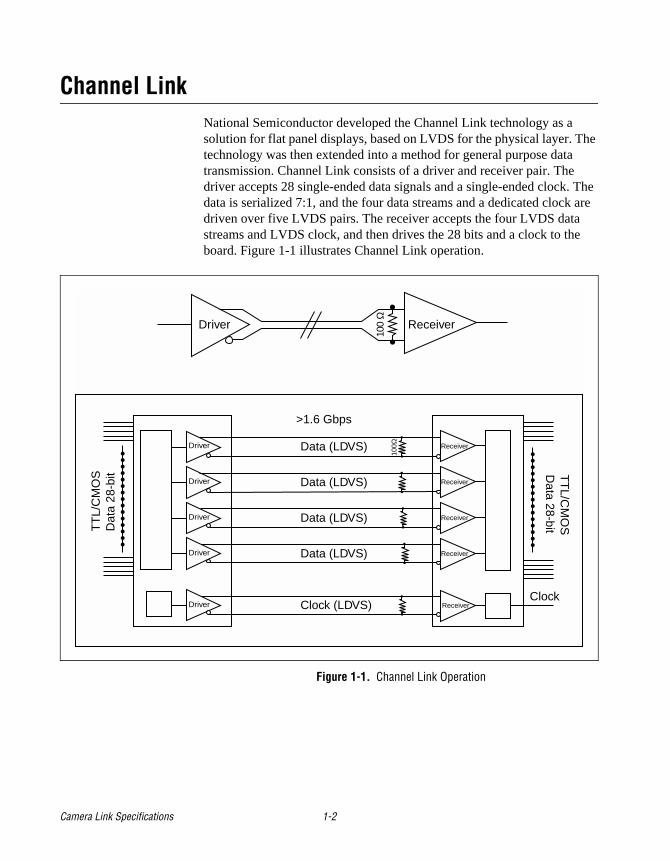
Channel Link National Semiconductor developed the Channel Link technology as a solution for flat panel displays, based on LVDS for the physical layer. The technology was then extended into a method for general purpose data transmission. Channel Link consists of a driver and receiver pair. The driver accepts 28 single-ended data signals and a single-ended clock. The data is serialized 7:1, and the four data streams and a dedicated clock are driven over five LVDS pairs. The receiver accepts the four LVDS data streams and LVDS clock, and then drives the 28 bits and a clock to the board. Figure 1-1 illustrates Channel Link operation.
Figure 1-1. Channel Link Operation
Receiver
Receiver
Receiver
Receiver
ReceiverDriver
Driver
Driver
Driver
Driver
>1.6 Gbps
Data (LDVS)
Data (LDVS)
Data (LDVS)
Data (LDVS)
Clock (LDVS)
TT
L/C
MO
SD
ata
28-b
it TT
L/CM
OS
Data 28-bit
Clock
ReceiverDriver
100Ω
100
Ω
Camera Link Specifications 1-2
Technology Benefits
Smaller Connectors and CablesChannel Link’s transmission method requires fewer conductors to transfer data. Five pairs of wires can transmit up to 28 bits of data. These wires reduce the size of the connector, allowing smaller cameras to be manufactured.
High Data Transmission RatesThe data transmission rates of the Channel Link chipset (up to 2.38 Gbits/s) support the current trend of increasing transfer speeds.
1-3 Camera Link Specifications
2-1 Camera L
2
Camera Signal RequirementsThis section provides definitions for the signals used in the Camera Link interface. The standard Camera Link cable provides camera control signals, serial communication, and video data.
Video DataThe Channel Link technology is integral to the transmission of video data. Image data and image enables are transmitted on the Channel Link bus. Four enable signals are defined as:
• FVAL—Frame Valid (FVAL) is defined HIGH for valid lines.
• LVAL—Line Valid (LVAL) is defined HIGH for valid pixels.
• DVAL—Data Valid (DVAL) is defined HIGH when data is valid.
• Spare— A spare has been defined for future use.
All four enables must be provided by the camera on each Channel Link chip. All unused data bits must be tied to a known value by the camera.
For more information on image data bit allocations, see Section 3, Bit Assignments, and Appendix C, Bit Assignments According to Configuration.
Camera Control SignalsFour LVDS pairs are reserved for general-purpose camera control. They are defined as camera inputs and frame grabber outputs. Camera manufacturers can define these signals to meet their needs for a particular product. The signals are:
• Camera Control 1 (CC1)
• Camera Control 2 (CC2)
• Camera Control 3 (CC3)
• Camera Control 4 (CC4)
ink Specifications
CommunicationTwo LVDS pairs have been allocated for asynchronous serial communication to and from the camera and frame grabber. Cameras and frame grabbers should support at least 9600 baud. These signals are
• SerTFG—Differential pair with serial communications to the frame grabber.
• SerTC—Differential pair with serial communications to the camera.
The serial interface will have the following characteristics: one start bit, one stop bit, no parity, and no handshaking.
It is recommended that frame grabber manufacturers supply both a user interface and a software application programmming interface (API) for using the asynchronous serial communication port. The user interface will consist of a terminal program with minimal capabilities of sending and receiving a character string and sending a file of bytes. The software API will provide functions to enumerate boards and send or receive a character string. See Appendix B, API Functions, for a suggested software application program interface (API).
PowerPower will not be provided on the Camera Link connector. The camera will receive power through a separate cable. Each camera manufacturer will define their own power connector, current, and voltage requirements.
Camera Link Specifications 2-2
3-1 Camera L
3
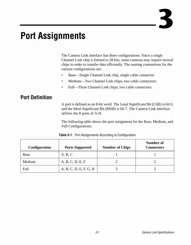
Port AssignmentsThe Camera Link interface has three configurations. Since a single Channel Link chip is limited to 28 bits, some cameras may require several chips in order to transfer data efficiently. The naming conventions for the various configurations are:
• Base—Single Channel Link chip, single cable connector.
• Medium—Two Channel Link chips, two cable connectors.
• Full—Three Channel Link chips, two cable connectors.
Port DefinitionA port is defined as an 8-bit word. The Least Significant Bit (LSB) is bit 0, and the Most Significant Bit (MSB) is bit 7. The Camera Link interface utilizes the 8 ports of A-H.
The following table shows the port assignment for the Base, Medium, and Full Configurations.
Table 3-1. Port Assignments According to Configuration
Configuration Ports Supported Number of ChipsNumber of Connectors
Base A, B, C 1 1
Medium A, B, C, D, E, F 2 2
Full A, B, C, D, E, F, G, H 3 2
ink Specifications
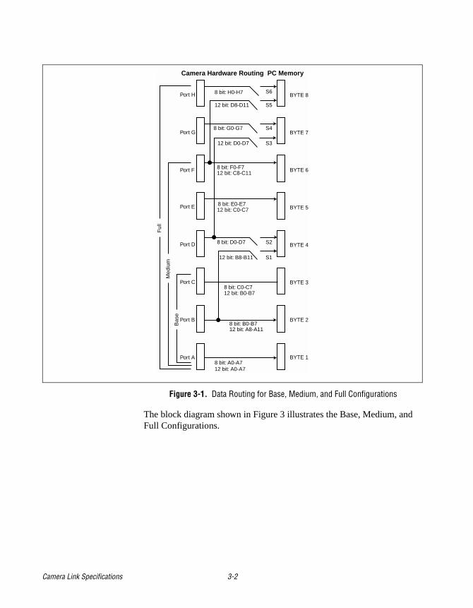
Figure 3-1. Data Routing for Base, Medium, and Full Configurations
The block diagram shown in Figure 3 illustrates the Base, Medium, and Full Configurations.
8 bit: H0-H7 S6BYTE 8
BYTE 7
BYTE 2
BYTE 3
BYTE 4
BYTE 5
BYTE 6
BYTE 1
12 bit: D8-D11 S5
S4
S3
S2
S1
Port H
Port G
Port F
Port E
Port D
Port C
Port B
Port A
12 bit: A0-A78 bit: A0-A7
12 bit: A8-A118 bit: B0-B7
12 bit: B0-B78 bit: C0-C7
12 bit: B8-B11
8 bit: D0-D7
12 bit: C8-C118 bit: F0-F7
12 bit: D0-D7
8 bit: G0-G7
12 bit: C0-C78 bit: E0-E7
Ful
l
Med
ium
Bas
e
Camera Hardware Routing PC Memory
Camera Link Specifications 3-2
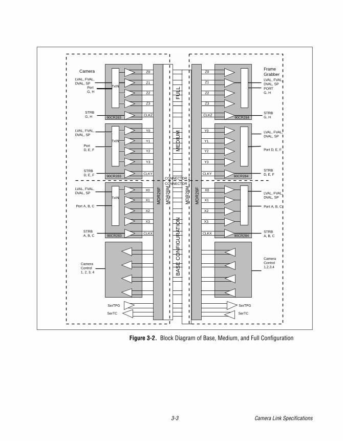
Figure 3-2. Block Diagram of Base, Medium, and Full Configuration
SerTFG
SerTC
SerTFG
SerTC
FrameGrabber
CameraControl1, 2, 3, 4
CameraControl1,2,3,4
Port A, B, C
STRBA, B, C
PortD, E, F
Camera
LVAL, FVAL,DVAL, SP
PortG, H
LVAL, FVAL,DVAL, SP LVAL, FVAL,
DVAL, SP
LVAL, FVAL,DVAL, SP
LVAL, FVAL,DVAL, SPPORT G, H
STRBG, H
STRBG, H
LVAL, FVAL,DVAL, SP
Port D, E, F
STRB D, E, F
STRB D, E, F
STRBA, B, C
Port A, B, C
Z0
Z1
Z2
Z3
CLKZ
Z0
Z1
Y0
Y1
Y2
Y3
Z2
Z3
Y0
Y1
Y2
Y3
CLKY
X0
CLKY
X1
X2
X3
X0
X1
X2
X3
CLKX CLKX
CONNECTOR 1
CONNECTOR 2B
AS
E C
ON
FIG
UR
ATIO
NM
ED
IUM
FU
LL
90CR283
90CR28490CR283
90CR28490CR283
90CR284
MD
R26
F
MD
R26
F
MD
R26
M
MD
R26
M
TxIN
TxIN
TxIN
CLKZ
3-3 Camera Link Specifications
4-1 Camera L
4
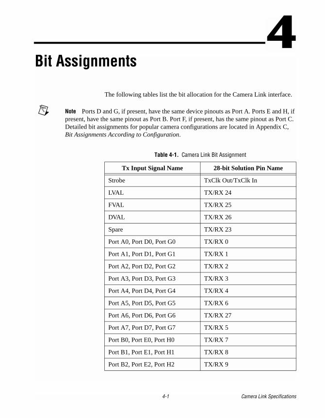
Bit AssignmentsThe following tables list the bit allocation for the Camera Link interface.
Note Ports D and G, if present, have the same device pinouts as Port A. Ports E and H, if present, have the same pinout as Port B. Port F, if present, has the same pinout as Port C. Detailed bit assignments for popular camera configurations are located in Appendix C, Bit Assignments According to Configuration.
Table 4-1. Camera Link Bit Assignment
Tx Input Signal Name 28-bit Solution Pin Name
Strobe TxClk Out/TxClk In
LVAL TX/RX 24
FVAL TX/RX 25
DVAL TX/RX 26
Spare TX/RX 23
Port A0, Port D0, Port G0 TX/RX 0
Port A1, Port D1, Port G1 TX/RX 1
Port A2, Port D2, Port G2 TX/RX 2
Port A3, Port D3, Port G3 TX/RX 3
Port A4, Port D4, Port G4 TX/RX 4
Port A5, Port D5, Port G5 TX/RX 6
Port A6, Port D6, Port G6 TX/RX 27
Port A7, Port D7, Port G7 TX/RX 5
Port B0, Port E0, Port H0 TX/RX 7
Port B1, Port E1, Port H1 TX/RX 8
Port B2, Port E2, Port H2 TX/RX 9
ink Specifications
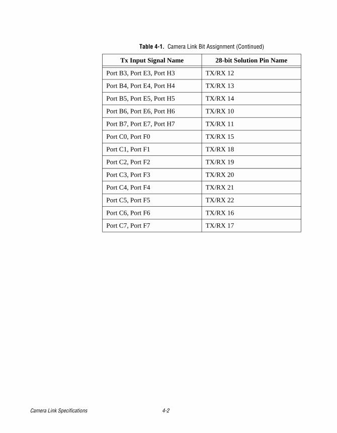
Port B3, Port E3, Port H3 TX/RX 12
Port B4, Port E4, Port H4 TX/RX 13
Port B5, Port E5, Port H5 TX/RX 14
Port B6, Port E6, Port H6 TX/RX 10
Port B7, Port E7, Port H7 TX/RX 11
Port C0, Port F0 TX/RX 15
Port C1, Port F1 TX/RX 18
Port C2, Port F2 TX/RX 19
Port C3, Port F3 TX/RX 20
Port C4, Port F4 TX/RX 21
Port C5, Port F5 TX/RX 22
Port C6, Port F6 TX/RX 16
Port C7, Port F7 TX/RX 17
Table 4-1. Camera Link Bit Assignment (Continued)
Tx Input Signal Name 28-bit Solution Pin Name
Camera Link Specifications 4-2
5-1 Camera L
5
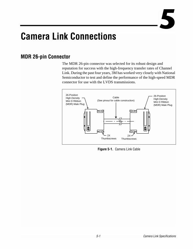
Camera Link ConnectionsMDR 26-pin ConnectorThe MDR 26-pin connector was selected for its robust design and reputation for success with the high-frequency transfer rates of Channel Link. During the past four years, 3M has worked very closely with National Semiconductor to test and define the performance of the high-speed MDR connector for use with the LVDS transmissions.
Figure 5-1. Camera Link Cable
26-PositionHigh-DensityMini D Ribbon(MDR) Male Plug
Cable(See pinout for cable construction)
2XThumbscrews
2XThumbscrews
26-PositionHigh-DensityMini D Ribbon(MDR) Male Plug
ink Specifications
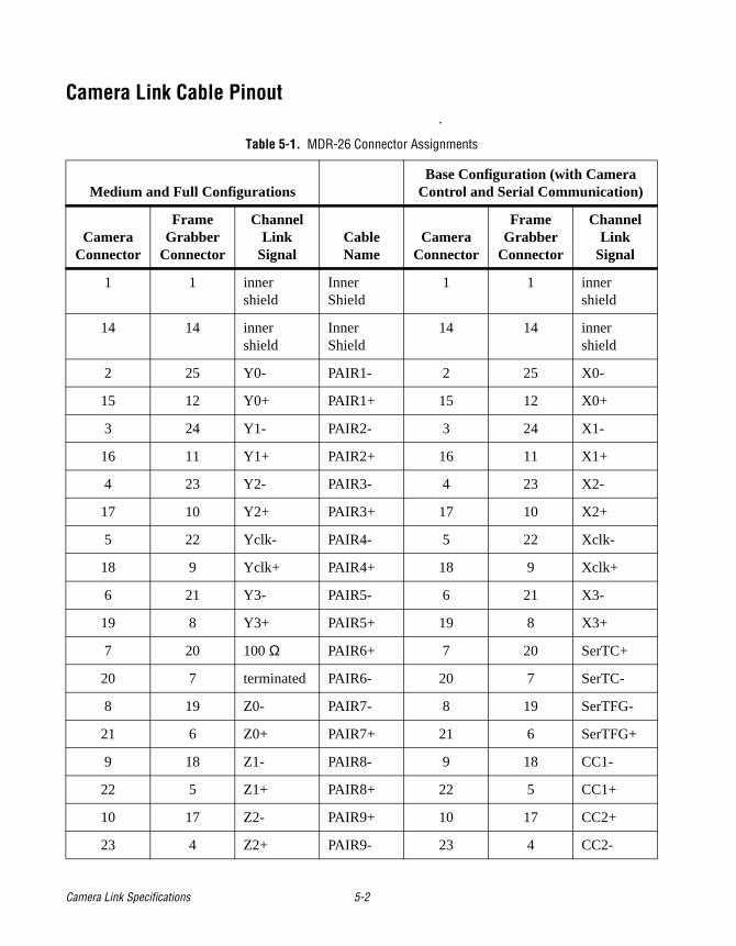
Camera Link Cable Pinout.
Table 5-1. MDR-26 Connector Assignments
Medium and Full ConfigurationsBase Configuration (with Camera
Control and Serial Communication)
Camera Connector
Frame Grabber
Connector
Channel Link
SignalCable Name
Camera Connector
Frame Grabber
Connector
Channel Link
Signal
1 1 inner shield
Inner Shield
1 1 inner shield
14 14 inner shield
Inner Shield
14 14 inner shield
2 25 Y0- PAIR1- 2 25 X0-
15 12 Y0+ PAIR1+ 15 12 X0+
3 24 Y1- PAIR2- 3 24 X1-
16 11 Y1+ PAIR2+ 16 11 X1+
4 23 Y2- PAIR3- 4 23 X2-
17 10 Y2+ PAIR3+ 17 10 X2+
5 22 Yclk- PAIR4- 5 22 Xclk-
18 9 Yclk+ PAIR4+ 18 9 Xclk+
6 21 Y3- PAIR5- 6 21 X3-
19 8 Y3+ PAIR5+ 19 8 X3+
7 20 100 Ω PAIR6+ 7 20 SerTC+
20 7 terminated PAIR6- 20 7 SerTC-
8 19 Z0- PAIR7- 8 19 SerTFG-
21 6 Z0+ PAIR7+ 21 6 SerTFG+
9 18 Z1- PAIR8- 9 18 CC1-
22 5 Z1+ PAIR8+ 22 5 CC1+
10 17 Z2- PAIR9+ 10 17 CC2+
23 4 Z2+ PAIR9- 23 4 CC2-
Camera Link Specifications 5-2
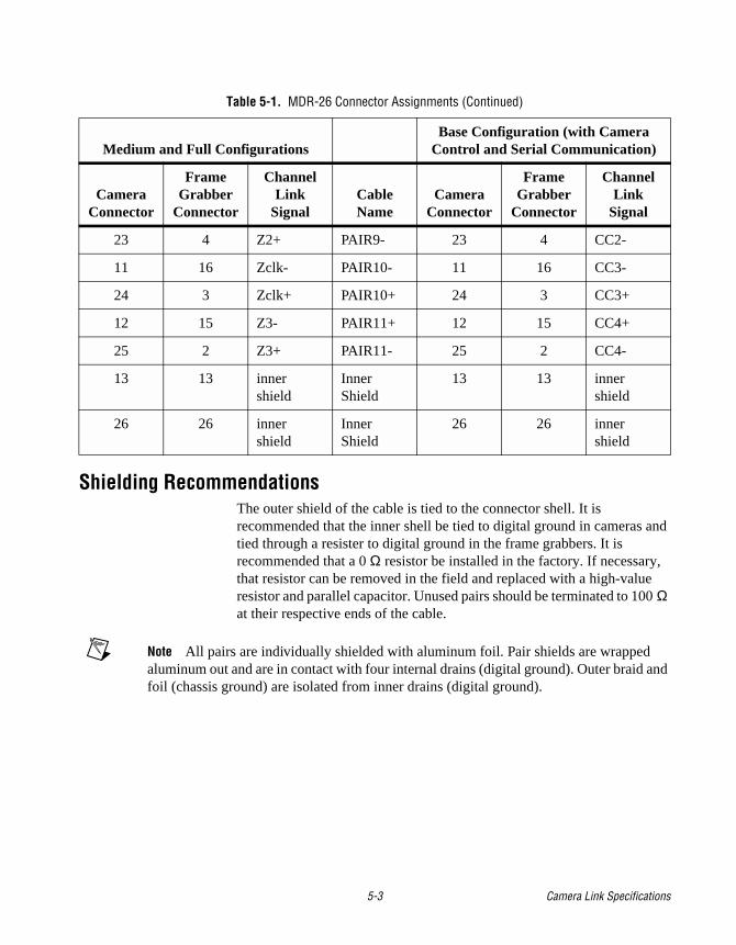
Shielding RecommendationsThe outer shield of the cable is tied to the connector shell. It is recommended that the inner shell be tied to digital ground in cameras and tied through a resister to digital ground in the frame grabbers. It is recommended that a 0 Ω resistor be installed in the factory. If necessary, that resistor can be removed in the field and replaced with a high-value resistor and parallel capacitor. Unused pairs should be terminated to 100 Ω at their respective ends of the cable.
Note All pairs are individually shielded with aluminum foil. Pair shields are wrapped aluminum out and are in contact with four internal drains (digital ground). Outer braid and foil (chassis ground) are isolated from inner drains (digital ground).
23 4 Z2+ PAIR9- 23 4 CC2-
11 16 Zclk- PAIR10- 11 16 CC3-
24 3 Zclk+ PAIR10+ 24 3 CC3+
12 15 Z3- PAIR11+ 12 15 CC4+
25 2 Z3+ PAIR11- 25 2 CC4-
13 13 inner shield
Inner Shield
13 13 inner shield
26 26 inner shield
Inner Shield
26 26 inner shield
Table 5-1. MDR-26 Connector Assignments (Continued)
Medium and Full ConfigurationsBase Configuration (with Camera
Control and Serial Communication)
Camera Connector
Frame Grabber
Connector
Channel Link
SignalCable Name
Camera Connector
Frame Grabber
Connector
Channel Link
Signal
5-3 Camera Link Specifications
A-1 Camera L
A
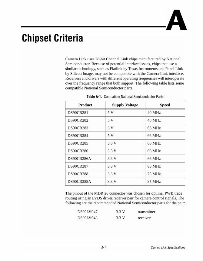
Chipset CriteriaCamera Link uses 28-bit Channel Link chips manufactured by National Semiconductor. Because of potential interface issues, chips that use a similar technology, such as Flatlink by Texas Instruments and Panel Link by Silicon Image, may not be compatible with the Camera Link interface. Receivers and drivers with different operating frequencies will interoperate over the frequency range that both support. The following table lists some compatible National Semiconductor parts.
The pinout of the MDR 26 connector was chosen for optimal PWB trace routing using an LVDS driver/receiver pair for camera control signals. The following are the recommended National Semiconductor parts for the pair:
DS90LV047 3.3 V transmitter
DS90LV048 3.3 V receiver
Table A-1. Compatible National Semiconductor Parts
Product Supply Voltage Speed
DS90CR281 5 V 40 MHz
DS90CR282 5 V 40 MHz
DS90CR283 5 V 66 MHz
DS90CR284 5 V 66 MHz
DS90CR285 3.3 V 66 MHz
DS90CR286 3.3 V 66 MHz
DS90CR286A 3.3 V 66 MHz
DS90CR287 3.3 V 85 MHz
DS90CR288 3.3 V 75 MHz
DS90CR288A 3.3 V 85 MHz
ink Specifications
B-1 Camera L
B
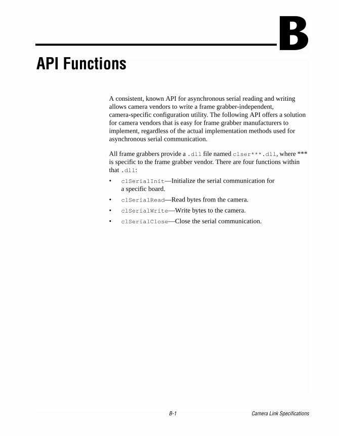
API FunctionsA consistent, known API for asynchronous serial reading and writing allows camera vendors to write a frame grabber-independent, camera-specific configuration utility. The following API offers a solution for camera vendors that is easy for frame grabber manufacturers to implement, regardless of the actual implementation methods used for asynchronous serial communication.
All frame grabbers provide a .dll file named clser***.dll, where *** is specific to the frame grabber vendor. There are four functions withinthat .dll:
• clSerialInit—Initialize the serial communication for a specific board.
• clSerialRead—Read bytes from the camera.
• clSerialWrite—Write bytes to the camera.
• clSerialClose—Close the serial communication.
ink Specifications
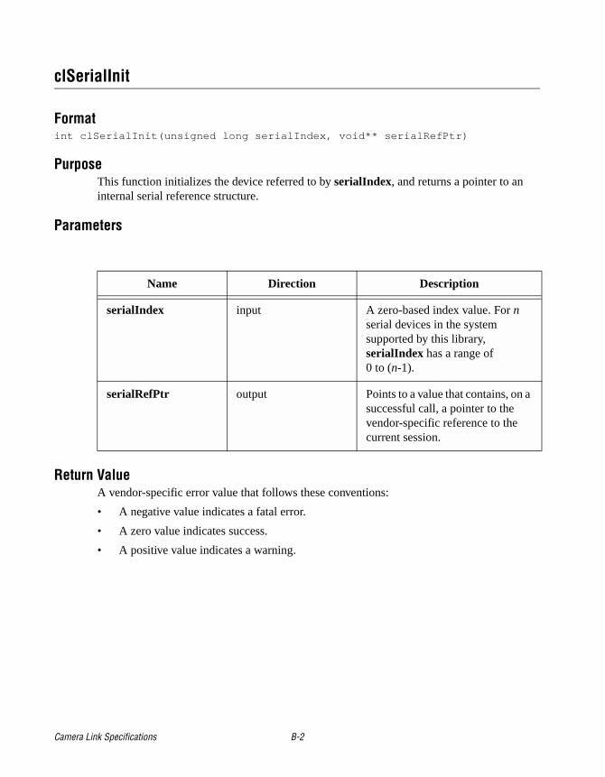
clSerialInit
Formatint clSerialInit(unsigned long serialIndex, void** serialRefPtr)
PurposeThis function initializes the device referred to by serialIndex, and returns a pointer to an internal serial reference structure.
Parameters
Return ValueA vendor-specific error value that follows these conventions:
• A negative value indicates a fatal error.
• A zero value indicates success.
• A positive value indicates a warning.
Name Direction Description
serialIndex input A zero-based index value. For n serial devices in the system supported by this library, serialIndex has a range of 0 to (n-1).
serialRefPtr output Points to a value that contains, on a successful call, a pointer to the vendor-specific reference to the current session.
Camera Link Specifications B-2
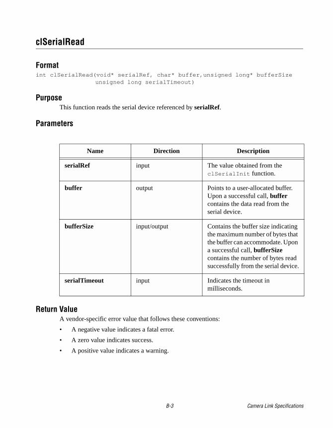
clSerialRead
Formatint clSerialRead(void* serialRef, char* buffer,unsigned long* bufferSize
unsigned long serialTimeout)
PurposeThis function reads the serial device referenced by serialRef.
Parameters
Return ValueA vendor-specific error value that follows these conventions:
• A negative value indicates a fatal error.
• A zero value indicates success.
• A positive value indicates a warning.
Name Direction Description
serialRef input The value obtained from the clSerialInit function.
buffer output Points to a user-allocated buffer. Upon a successful call, buffer contains the data read from the serial device.
bufferSize input/output Contains the buffer size indicating the maximum number of bytes that the buffer can accommodate. Upon a successful call, bufferSize contains the number of bytes read successfully from the serial device.
serialTimeout input Indicates the timeout in milliseconds.
B-3 Camera Link Specifications
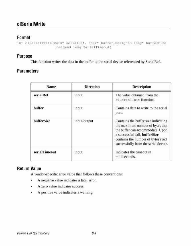
clSerialWrite
Formatint clSerialWrite(void* serialRef, char* buffer,unsigned long* bufferSize
unsigned long SerialTimeout)
PurposeThis function writes the data in the buffer to the serial device referenced by SerialRef.
Parameters
Return ValueA vendor-specific error value that follows these conventions:
• A negative value indicates a fatal error.
• A zero value indicates success.
• A positive value indicates a warning.
Name Direction Description
serialRef input The value obtained from the clSerialInit function.
buffer input Contains data to write to the serial port.
bufferSize input/output Contains the buffer size indicating the maximum number of bytes that the buffer can accommodate. Upon a successful call, bufferSize contains the number of bytes read successfully from the serial device.
serialTimeout input Indicates the timeout in milliseconds.
Camera Link Specifications B-4
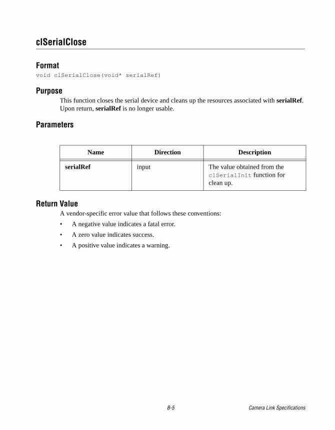
clSerialClose
Formatvoid clSerialClose(void* serialRef)
PurposeThis function closes the serial device and cleans up the resources associated with serialRef. Upon return, serialRef is no longer usable.
Parameters
Return ValueA vendor-specific error value that follows these conventions:
• A negative value indicates a fatal error.
• A zero value indicates success.
• A positive value indicates a warning.
Name Direction Description
serialRef input The value obtained from the clSerialInit function forclean up.
B-5 Camera Link Specifications
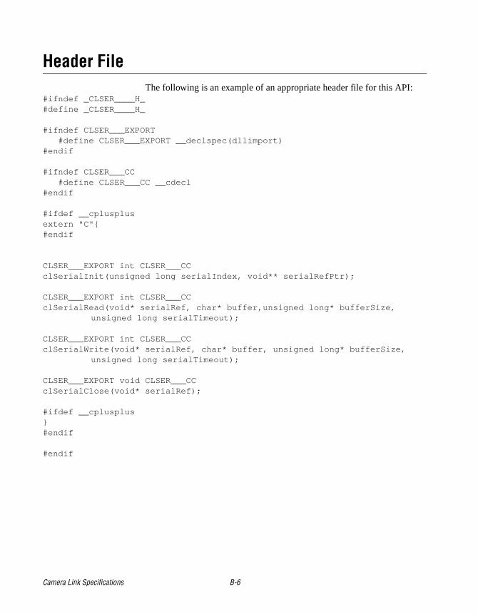
Header FileThe following is an example of an appropriate header file for this API:
#ifndef _CLSER____H_#define _CLSER____H_
#ifndef CLSER___EXPORT #define CLSER___EXPORT __declspec(dllimport)#endif
#ifndef CLSER___CC #define CLSER___CC __cdecl#endif
#ifdef __cplusplusextern "C"#endif
CLSER___EXPORT int CLSER___CCclSerialInit(unsigned long serialIndex, void** serialRefPtr);
CLSER___EXPORT int CLSER___CC clSerialRead(void* serialRef, char* buffer,unsigned long* bufferSize,
unsigned long serialTimeout);
CLSER___EXPORT int CLSER___CC clSerialWrite(void* serialRef, char* buffer, unsigned long* bufferSize,
unsigned long serialTimeout);
CLSER___EXPORT void CLSER___CC clSerialClose(void* serialRef);
#ifdef __cplusplus#endif
#endif
Camera Link Specifications B-6
Note Using a single .dll file prevents the user from accessing driver software from multiple vendors at the same time; therefore, camera vendors using this API must load all .dll files with the name clser*.dll on the system and then provide a method for the user to select the correct vendor for the board they are using. The camera vendor should use LoadLibrary and GetProcAddress to find these functions. The camera vendors should also provide a way for users to select a particular frame grabber, and then use clSerialRead and clSerialWrite to communicate with the camera attached to their board.
B-7 Camera Link Specifications
C-1 Camera L
C
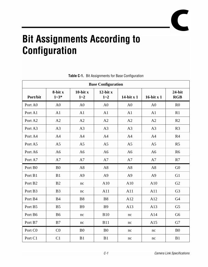
Bit Assignments According to ConfigurationTable C-1. Bit Assignments for Base Configuration
Base Configuration
Port/bit8-bit x 1~3*
10-bit x 1~2
12-bit x 1~2 14-bit x 1 16-bit x 1
24-bit RGB
Port A0 A0 A0 A0 A0 A0 R0
Port A1 A1 A1 A1 A1 A1 R1
Port A2 A2 A2 A2 A2 A2 R2
Port A3 A3 A3 A3 A3 A3 R3
Port A4 A4 A4 A4 A4 A4 R4
Port A5 A5 A5 A5 A5 A5 R5
Port A6 A6 A6 A6 A6 A6 R6
Port A7 A7 A7 A7 A7 A7 R7
Port B0 B0 A8 A8 A8 A8 G0
Port B1 B1 A9 A9 A9 A9 G1
Port B2 B2 nc A10 A10 A10 G2
Port B3 B3 nc A11 A11 A11 G3
Port B4 B4 B8 B8 A12 A12 G4
Port B5 B5 B9 B9 A13 A13 G5
Port B6 B6 nc B10 nc A14 G6
Port B7 B7 nc B11 nc A15 G7
Port C0 C0 B0 B0 nc nc B0
Port C1 C1 B1 B1 nc nc B1
ink Specifications
Port C2 C2 B2 B2 nc nc B2
Port C3 C3 B3 B3 nc nc B3
Port C4 C4 B4 B4 nc nc B4
Port C5 C5 B5 B5 nc nc B5
Port C6 C6 B6 B6 nc nc B6
Port C7 C7 B7 B7 nc nc B7
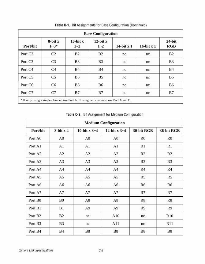
* If only using a single channel, use Port A. If using two channels, use Port A and B.
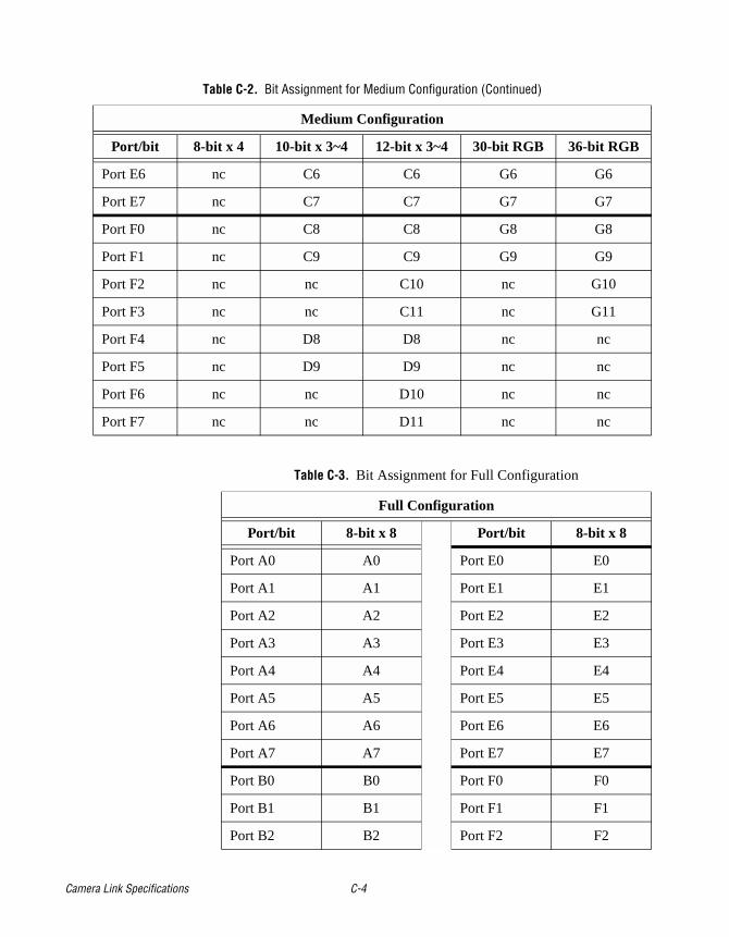
Table C-2. Bit Assignment for Medium Configuration
Medium Configuration
Port/bit 8-bit x 4 10-bit x 3~4 12-bit x 3~4 30-bit RGB 36-bit RGB
Port A0 A0 A0 A0 R0 R0
Port A1 A1 A1 A1 R1 R1
Port A2 A2 A2 A2 R2 R2
Port A3 A3 A3 A3 R3 R3
Port A4 A4 A4 A4 R4 R4
Port A5 A5 A5 A5 R5 R5
Port A6 A6 A6 A6 R6 R6
Port A7 A7 A7 A7 R7 R7
Port B0 B0 A8 A8 R8 R8
Port B1 B1 A9 A9 R9 R9
Port B2 B2 nc A10 nc R10
Port B3 B3 nc A11 nc R11
Port B4 B4 B8 B8 B8 B8
Table C-1. Bit Assignments for Base Configuration (Continued)
Base Configuration
Port/bit8-bit x 1~3*
10-bit x 1~2
12-bit x 1~2 14-bit x 1 16-bit x 1
24-bit RGB
Camera Link Specifications C-2
Port B5 B5 B9 B9 B9 B9
Port B6 B6 nc B10 nc B10
Port B7 B7 nc B11 nc B11
Port C0 C0 B0 B0 B0 B0
Port C1 C1 B1 B1 B1 B1
Port C2 C2 B2 B2 B2 B2
Port C3 C3 B3 B3 B3 B3
Port C4 C4 B4 B4 B4 B4
Port C5 C5 B5 B5 B5 B5
Port C6 C6 B6 B6 B6 B6
Port C7 C7 B7 B7 B7 B7
Port D0 D0 D0 D0 nc nc
Port D1 D1 D1 D1 nc nc
Port D2 D2 D2 D2 nc nc
Port D3 D3 D3 D3 nc nc
Port D4 D4 D4 D4 nc nc
Port D5 D5 D5 D5 nc nc
Port D6 D6 D6 D6 nc nc
Port D7 D7 D7 D7 nc nc
Port E0 nc C0 C0 G0 G0
Port E1 nc C1 C1 G1 G1
Port E2 nc C2 C2 G2 G2
Port E3 nc C3 C3 G3 G3
Port E4 nc C4 C4 G4 G4
Port E5 nc C5 C5 G5 G5
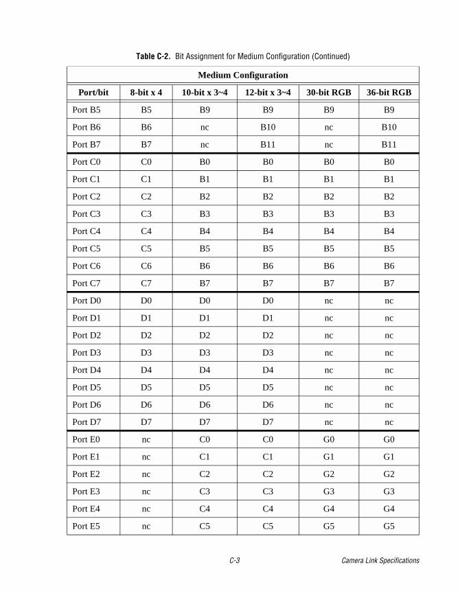
Table C-2. Bit Assignment for Medium Configuration (Continued)
Medium Configuration
Port/bit 8-bit x 4 10-bit x 3~4 12-bit x 3~4 30-bit RGB 36-bit RGB
C-3 Camera Link Specifications
Port E6 nc C6 C6 G6 G6
Port E7 nc C7 C7 G7 G7
Port F0 nc C8 C8 G8 G8
Port F1 nc C9 C9 G9 G9
Port F2 nc nc C10 nc G10
Port F3 nc nc C11 nc G11
Port F4 nc D8 D8 nc nc
Port F5 nc D9 D9 nc nc
Port F6 nc nc D10 nc nc
Port F7 nc nc D11 nc nc
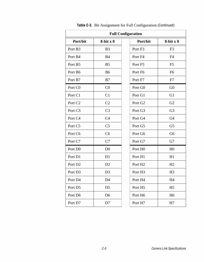
Table C-3. Bit Assignment for Full Configuration
Full Configuration
Port/bit 8-bit x 8 Port/bit 8-bit x 8
Port A0 A0 Port E0 E0
Port A1 A1 Port E1 E1
Port A2 A2 Port E2 E2
Port A3 A3 Port E3 E3
Port A4 A4 Port E4 E4
Port A5 A5 Port E5 E5
Port A6 A6 Port E6 E6
Port A7 A7 Port E7 E7
Port B0 B0 Port F0 F0
Port B1 B1 Port F1 F1
Port B2 B2 Port F2 F2
Table C-2. Bit Assignment for Medium Configuration (Continued)
Medium Configuration
Port/bit 8-bit x 4 10-bit x 3~4 12-bit x 3~4 30-bit RGB 36-bit RGB
Camera Link Specifications C-4
Port B3 B3 Port F3 F3
Port B4 B4 Port F4 F4
Port B5 B5 Port F5 F5
Port B6 B6 Port F6 F6
Port B7 B7 Port F7 F7
Port C0 C0 Port G0 G0
Port C1 C1 Port G1 G1
Port C2 C2 Port G2 G2
Port C3 C3 Port G3 G3
Port C4 C4 Port G4 G4
Port C5 C5 Port G5 G5
Port C6 C6 Port G6 G6
Port C7 C7 Port G7 G7
Port D0 D0 Port H0 H0
Port D1 D1 Port H1 H1
Port D2 D2 Port H2 H2
Port D3 D3 Port H3 H3
Port D4 D4 Port H4 H4
Port D5 D5 Port H5 H5
Port D6 D6 Port H6 H6
Port D7 D7 Port H7 H7
Table C-3. Bit Assignment for Full Configuration (Continued)
Full Configuration
Port/bit 8-bit x 8 Port/bit 8-bit x 8
C-5 Camera Link Specifications
D-1 Camera L
D
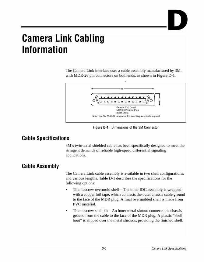
Camera Link Cabling InformationThe Camera Link interface uses a cable assembly manufactured by 3M, with MDR-26 pin connectors on both ends, as shown in Figure D-1.
.
Figure D-1. Dimensions of the 3M Connector
Cable Specifications3M’s twin-axial shielded cable has been specifically designed to meet the stringent demands of reliable high-speed differential signaling applications.
Cable AssemblyThe Camera Link cable assembly is available in two shell configurations, and various lengths. Table D-1 describes the specifications for the following options:
• Thumbscrew overmold shell—The inner IDC assembly is wrapped with a copper foil tape, which connects the outer chassis cable ground to the face of the MDR plug. A final overmolded shell is made from PVC material.
• Thumbscrew shell kit—An inner metal shroud connects the chassis ground from the cable to the face of the MDR plug. A plastic “shell boot” is slipped over the metal shrouds, providing the finished shell.
1
14 15 16
11 12 13
24 25 26
Generic End DetailMDR 26 Position Plug(Both Ends)
5
17 18 19
7 8
20 21 22
10
23
B
C
Note: Use 3M 3341-31 jacksocket for mounting receptacle to panel.
32 4 6 9
ink Specifications
Ordering Information
Cable assemblies and boardmount receptacles are available from 3M. For more information on 3M products, see the 3M Web site at www.3M.com.
Cable Assembly Part Numbers
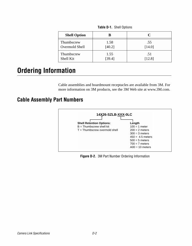
Figure D-2. 3M Part Number Ordering Information
Table D-1. Shell Options
Shell Option B C
Thumbscrew Overmold Shell
1.58[40.2]
.55[14.0]
Thumbscrew Shell Kit
1.55[39.4]
.51[12.8]
14X26-SZLB-XXX-0LC
Length100 = 1 meter200 = 2 meters300 = 3 meters450 = 4.5 meters500 = 5 meters700 = 7 metersA00 = 10 meters
Shell Retention Options:B = Thumbscrew shell kitT = Thumbscrew overmold shell
Camera Link Specifications D-2
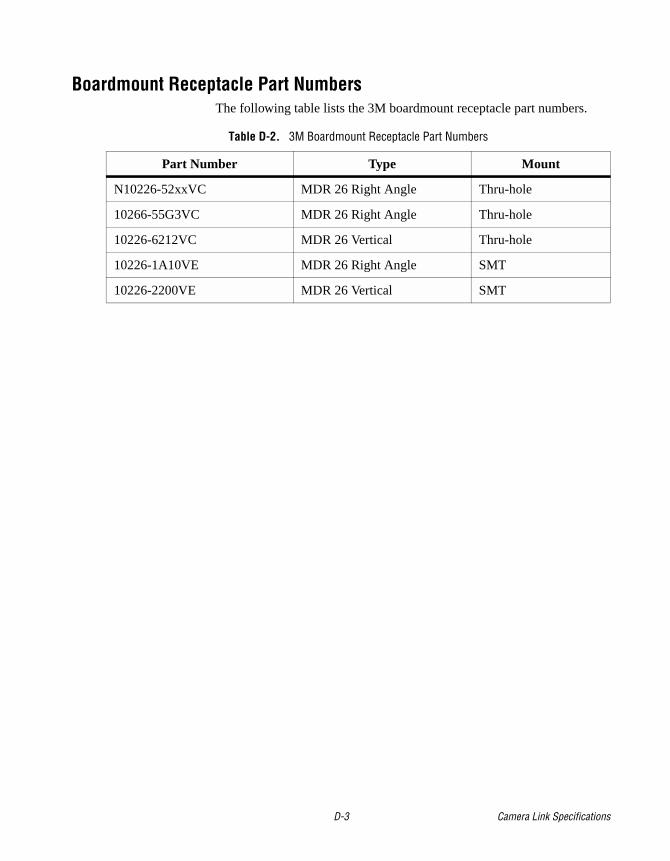
Boardmount Receptacle Part NumbersThe following table lists the 3M boardmount receptacle part numbers.
Table D-2. 3M Boardmount Receptacle Part Numbers
Part Number Type Mount
N10226-52xxVC MDR 26 Right Angle Thru-hole
10266-55G3VC MDR 26 Right Angle Thru-hole
10226-6212VC MDR 26 Vertical Thru-hole
10226-1A10VE MDR 26 Right Angle SMT
10226-2200VE MDR 26 Vertical SMT
D-3 Camera Link Specifications
Related Documents