2250 / 2625 / 3000S CADMAN TRAVELLER OPERATOR’S and PARTS MANUAL 2001 EDITION

Welcome message from author
This document is posted to help you gain knowledge. Please leave a comment to let me know what you think about it! Share it to your friends and learn new things together.
Transcript
2250 / 2625 / 3000SCADMAN TRAVELLER
OPERATOR’S and PARTS MANUAL2001 EDITION

06/29/09
INDEX
Introduction ...................................................................................................................1
• Owner’s Responsibilities • Features
Safety Precautions .......................................................................................................2
• General Precautions • Safety Decals ..................................................................................................3 • Safety Shields • Stabilizer Legs • Gun Cart ..........................................................................................................4 • Applicators and Accessories
Required Maintenance ................................................................................................5
• Each Use • Daily • After First 25 Hours • Every 50 Hours • Every 100 Hours • Every 250 Hours..............................................................................................6 • Before Storing • Before Start-Up • Lubricants
Field Preparation and Operating Tips .....................................................................7 When Applying Liquid Manure..................................................................................8 Field Set-Up and Operation........................................................................................9 Indexing Adjustment .................................................................................................10 Start Up of the Retrieve Cycle .................................................................................13 Retrieve Rate Selection.............................................................................................15
• Example .......................................................................................................16 Nelson SR-100 Big Gun® Performance Chart ......................................................17 Application Charts .....................................................................................................18 Parts Section Index .......................................................................................... 19

2
SAFETY PRECAUTIONS
As the owner and / or operator it is ultimately your responsibility to insure personalsafety and to operate this machine in a safe manner. Your good judgment and the followingprecautions will help you to avoid costly accidents and minimize personal risk.
• DO NOT move or operate this machine until you have read and understand the instruc-tions in this manual.
• NEVER allow untrained persons to operate this machine.
• DO NOT attempt to service this machine while it is in operation.
• MAKE CERTAIN all mechanical and hydraulic tension has been released before attempt-ing to service the machine.
• CHECK all nuts and bolts regularly for tightness.
• PERFORM REQUIRED MAINTENANCE as prescribed or as necessary to keep this ma-chine in safe operating condition.
• KEEP ALL SPECTATORS at a safe distance.
• STAY CLEAR of high pressure supply lines, especially when first pressurizing the system.
• DO NOT remove or alter any of the shielding from this machine.
• BE CERTAIN that the machine is securely anchored (using the stabilizer legs) before un-spooling the hose.
• KEEP WELL CLEAR of all moving parts.
• NEVER tow this machine at speeds greater than 10 MPH / 15 KPH and be certain the towvehicle has adequate braking capacity to maintain safe control at all times.
GENERAL PRECAUTIONS
“SAFETY IS JUST A WORD UNTIL PUT INTO PRACTICE”
This symbol, the safety-alert symbol, indicates a hazard and conforms to ANSI/ ASAE S350. When you come across the safety-alert symbol in this manual,make certain you fully understand and abide by the given instructions.
Keep the chassis of the machine on firm and level ground. A Cadman Travellerhas a high center of gravity. It is essential that it be operated from a stable posi-tion to prevent roll over.

3
SAFETY DECALS
The safety decals on this machine are intended to warn the operator of potentially haz-ardous areas. These decals must be properly maintained. This includes;
• keeping all safety decals legible
• replacing any decal that becomes illegible
• replacing any decal that is missing
• if applicable, include the current safety decal specified by Cadman Power Equipment Ltd.on any component installed during repair
Contact Cadman Power Equipment Limited to obtain replacement safety decals.When replacing safety decals reinstall them onto there proper locations.
SAFETY SHIELDS
The shielding installed on your Cadman Traveller is designed to help guard againstaccidental entanglement in the moving parts of the machine. These shields must be removedONLY for the purpose of repair or periodic maintenance as described in the “Required Main-tenance” section of this manual. The shielding MUST be immediately re-installed BEFOREputting the machine back in service.
STABILIZER LEGS
All Cadman Travellers are equipped with two (2) stabilizer legs. The stabilizer legsMUST be lowered each time the machine is used, no matter how little hose is pulled out!
Regular inspection of your pipe couplings, tubing and gaskets should be part ofyour regular set-up routine. Any defective parts should be replaced or taken outof service.
Pressurizing your Cadman Traveller must be done slowly and cautiously topurge all the air from the system before bringing the system up to full operatingpressure. (see “Field Set Up And Operation” #16 on pg. 13 for further explana-tion)
WARNINGOperation of a Cadman Traveller without the shielding in place could re-sult in serious personal injury or death!
WARNINGFailure to properly use the stabilizer legs may result in unwanted framemovement or machine upset with the potential to cause serious injury or
4
APPLICATORS AND ACCESSORIES
There are a variety of applicators available to be used with your Cadman Traveller.Ask a Cadman Power Equipment Limited representative about your options.
Cadman Power Pak Caprari Water Sprinkler Kit
Many accessories are also available for use with a Cadman Traveller (i.e. CadmanPower Pak) Refer to there respective manuals before using any piece of equipment with yourCadman Traveller.
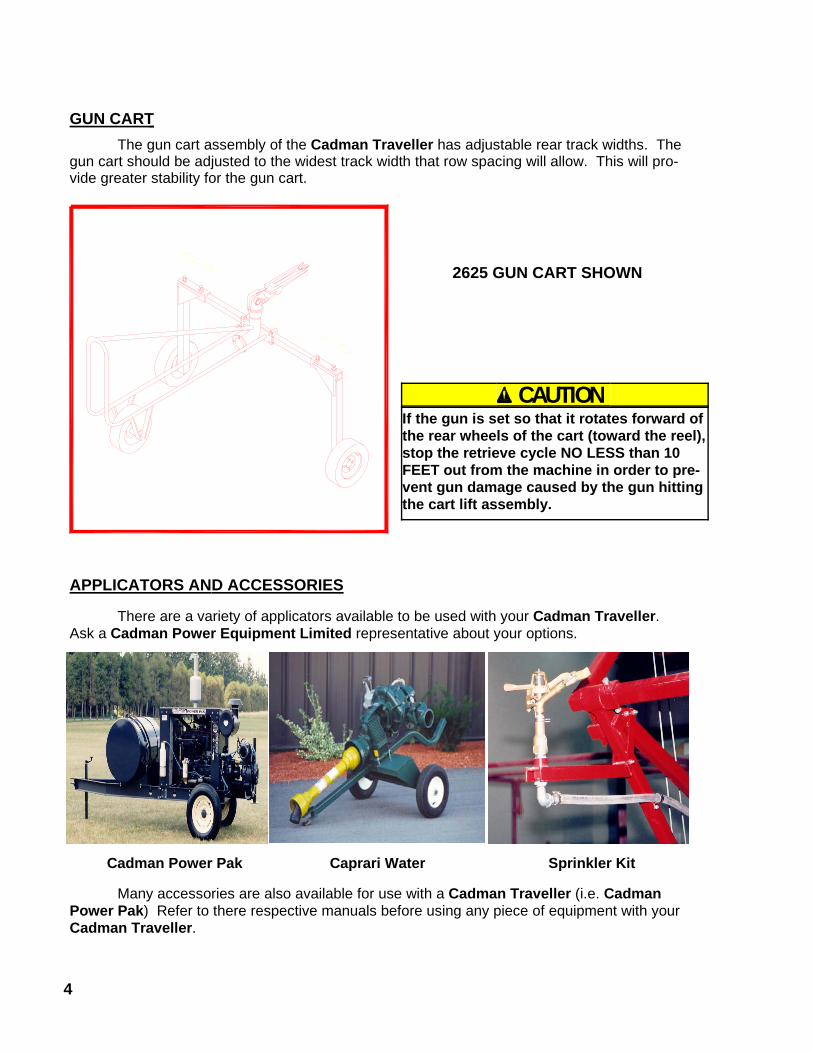
GUN CART The gun cart assembly of the Cadman Traveller has adjustable rear track widths. The
gun cart should be adjusted to the widest track width that row spacing will allow. This will pro-vide greater stability for the gun cart.
2625 GUN CART SHOWN
CAUTIONIf the gun is set so that it rotates forward ofthe rear wheels of the cart (toward the reel),stop the retrieve cycle NO LESS than 10FEET out from the machine in order to pre-vent gun damage caused by the gun hittingthe cart lift assembly.
5
REQUIRED MAINTENANCE
Prevention of mechanical failure is the goal of any good maintenance schedule. Severeservice uses such as liquid manure application, municipal and industrial uses, custom slurry ap-plications, etc. require timely, trouble free operation of your equipment. The secret to preventingunwanted down time is to adhere to a maintenance schedule suited to the way you use theequipment. Your maintenance schedule should include the following minimum requirements;
EACH USE
1 Check to be sure BOTH shut off switches and the safety shut off switch are working. Repairor replace a defective switch BEFORE operating the machine. (see top of pg.14)
2 Check to be sure the compensator safety switch is properly adjusted and working. The en-gine must shut down before the shut off bar contacts the frame. (see top of pg. 14)
DAILY
1 Check the engine oil level and air filter condi-tion.
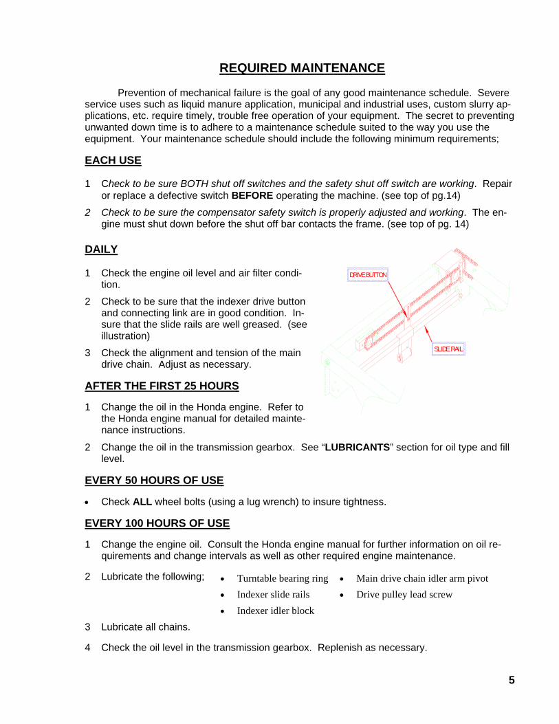
2 Check to be sure that the indexer drive buttonand connecting link are in good condition. In-sure that the slide rails are well greased. (seeillustration)
3 Check the alignment and tension of the maindrive chain. Adjust as necessary.
AFTER THE FIRST 25 HOURS
1 Change the oil in the Honda engine. Refer tothe Honda engine manual for detailed mainte-nance instructions.
2 Change the oil in the transmission gearbox. See “LUBRICANTS” section for oil type and filllevel.
EVERY 50 HOURS OF USE
• Check ALL wheel bolts (using a lug wrench) to insure tightness.
EVERY 100 HOURS OF USE
1 Change the engine oil. Consult the Honda engine manual for further information on oil re-quirements and change intervals as well as other required engine maintenance.
2 Lubricate the following;
3 Lubricate all chains.
4 Check the oil level in the transmission gearbox. Replenish as necessary.
• Turntable bearing ring• Indexer slide rails• Indexer idler block
• Main drive chain idler arm pivot• Drive pulley lead screw
SLIDE RAIL
DRIVE BUTTON

6
5 Check for oil level in the indexer gearbox.
6 Check the tire pressure and maintain from 36-40 PSI.
EVERY 250 HOURS OF USE
Disassemble, clean, inspect and re-pack the gun cartwheel bearings. Replace any defective components asrequired.
BEFORE STORING
1 Drain the hose. This is easily done by pulling out allbut one (1) coil of hose along a level path. Remove the drain plug from the gun cart. Use theHonda engine or a tractor PTO shaft to wind in the hose.
2 Disassemble and clean the variable speed pulley mounted on the engine. Remove the“moving face” of the pulley. Clean the bronze bushing and shaft of gum and belt dust and lu-bricate with a thin coat of light oil.
3 Disassemble, clean, inspect and re-pack the main chassis wheel bearings.
4 Lubricate all chains.
5 Prepare the Honda engine for storage. See the storage instructions provided in the Hondaengine manual.
BEFORE START UP (After long term storage)
1 Review this manual to refresh your memory regarding the proper operation of this machine.
2 Fill the fuel system with fresh fuel.
3 Change the oil in both the transmission gearbox and the indexer gearbox.
4 Check and adjust the tire pressure to 36 - 40 PSI.
LUBRICANTS
Grease: Any good grade of multi-purpose, waterproofgrease is acceptable.
Engine Oil: Consult the Honda owners’ manual for oilrecommendations.
Transmission Gearbox: SAE 80W or 90W gear oil.(see illustration)
Indexer Gearbox: Mobile SHC 634 Synthetic GearLubricant
DRAIN PLUG
FULL PLUG
FILLINGAREA
CAUTIONDO NOT leave the machine unattended during the hose draining process. Without fluid pres-sure present, the hose may flatten slightly causing it to lay improperly on the drum. It may benecessary to manually adjust the hose position on the hose drum during the draining process.
AS SHOWN WHEN CHECKING THE OIL LEVEL
THE OIL LEVEL HOLEFILL THE GEARBOX TO THE INSIDE LIP OF
7
FIELD PREPARATION AND OPERATING TIPS
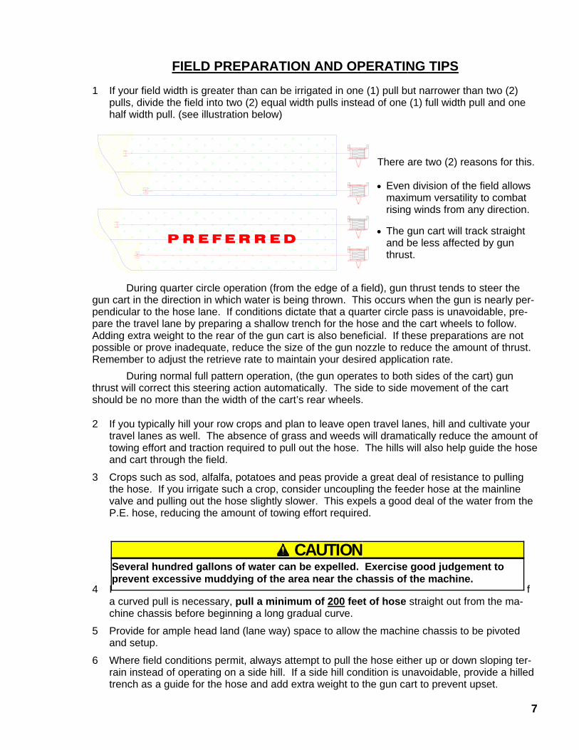
1 If your field width is greater than can be irrigated in one (1) pull but narrower than two (2)pulls, divide the field into two (2) equal width pulls instead of one (1) full width pull and onehalf width pull. (see illustration below)
There are two (2) reasons for this.
• Even division of the field allowsmaximum versatility to combatrising winds from any direction.
• The gun cart will track straightand be less affected by gunthrust.
During quarter circle operation (from the edge of a field), gun thrust tends to steer thegun cart in the direction in which water is being thrown. This occurs when the gun is nearly per-pendicular to the hose lane. If conditions dictate that a quarter circle pass is unavoidable, pre-pare the travel lane by preparing a shallow trench for the hose and the cart wheels to follow.Adding extra weight to the rear of the gun cart is also beneficial. If these preparations are notpossible or prove inadequate, reduce the size of the gun nozzle to reduce the amount of thrust.Remember to adjust the retrieve rate to maintain your desired application rate.
During normal full pattern operation, (the gun operates to both sides of the cart) gunthrust will correct this steering action automatically. The side to side movement of the cartshould be no more than the width of the cart’s rear wheels.
2 If you typically hill your row crops and plan to leave open travel lanes, hill and cultivate yourtravel lanes as well. The absence of grass and weeds will dramatically reduce the amount oftowing effort and traction required to pull out the hose. The hills will also help guide the hoseand cart through the field.
3 Crops such as sod, alfalfa, potatoes and peas provide a great deal of resistance to pullingthe hose. If you irrigate such a crop, consider uncoupling the feeder hose at the mainlinevalve and pulling out the hose slightly slower. This expels a good deal of the water from theP.E. hose, reducing the amount of towing effort required.
4 I fa curved pull is necessary, pull a minimum of 200 feet of hose straight out from the ma-chine chassis before beginning a long gradual curve.
5 Provide for ample head land (lane way) space to allow the machine chassis to be pivotedand setup.
6 Where field conditions permit, always attempt to pull the hose either up or down sloping ter-rain instead of operating on a side hill. If a side hill condition is unavoidable, provide a hilledtrench as a guide for the hose and add extra weight to the gun cart to prevent upset.
P R E F E R R E D
CAUTIONSeveral hundred gallons of water can be expelled. Exercise good judgement toprevent excessive muddying of the area near the chassis of the machine.

8
WHEN APPLYING LIQUID MANURE . . . Environmental concerns seem to be driving legislative agendas in many agricultural areas across the continent. Current and pending laws in many agricultural regions of North America are changing the ways in which the agricultural community is expected to manage their liquid animal waste products. The changes in legislation typically target two main issues; run-off prevention during and after application and soil nutrient loading. Run off seems to be the largest concern with nutrient application. Run off may result from several different factors, most of which are controllable. These factors include; exceeding the soil intake rate; nutrient application on steep grades; high application amounts; leaking mainline fittings and seals; sudden rainfall during or immediately after application; ground frost; etc. Constant watch must be kept and immediate action taken when necessary to prevent run off from occurring. Soil nutrient loading depends on many variables. Some of these variables (but certainly not all) are soil type, type of crop being grown in the irrigated area, application timing, nutrient value of the material being applied (nutrient value should be assessed at the time of application as it can change throughout the year), etc. Soil type will determine the intake rate at which liquid may be applied. Cultivation of the field just prior to application can improve the intake rate of some soils. Great potential benefit lies in using the nutritional value of the product being applied to replace some or all of the traditional chemical fertilizer used. Application timing and amount are important considerations. Soil analysis taken prior to planting and during the growth periods of the crop will help determine if there is room for further application amounts to be added prior to crop maturity. A total management plan should include provisions to end the crop season without surplus nutrients left as residual. These excess nutrients typically end up in the ground water supply. Local colleges, universities and agricultural extension services are usually a good source of information. They can usually help you determine an application program that prevents soil nutrient overload due to excess application. Cadman Power Equipment Limited cannot possibly provide up-to-date recommendations with regard to the legal obligations you must deal with in your particular area. However, as a manufacturer of equipment used in nutrient application (liquid manure, milk house run-off, etc.), we feel it necessary to make you aware that the municipal, regional and state governing bodies in your area may have recently enacted new legislation or revised existing legislation with regard to nutrient handling practices and procedures. It is your responsibility to make yourself aware of and abide by the current legislation in your area. Please take the time to contact your local agricultural representative to obtain the latest information regarding legal nutrient application and handling.
9
FIELD SET UP AND OPERATION
BEFORE operating your new CADMAN TRAVELLER, inspect the machine for anydamage or parts which may have come loose during shipping. REPORT ANY DAMAGE TOYOUR DEALER IMMEDIATELY !
1. Tow the machine to the field. Park the traveller on the head land (lane way) at right anglesto the rows to be irrigated.
NOTE : For the first use of a new machine or a machine which has been drained prior to stor-age, start in an area which will allow you to pull out the full length of hose ( EXCEPTfor one full coil ). This will allow you to be sure that the hose is properly laid on thebase layer and properly indexed.
If you are unable to pull out all of the hose in the area you are working, pull out enoughhose to reach the base layer. This will allow you to see if the coils of hose in the base layer arestacked tightly together. If the hose is found to be improperly indexed (the hose tries to climbup on itself or gaps exist between the coils of hose), do the following:
• Set the hose drum so that the hose connection is at the six o’clock position (closestto the ground).
• Fully apply the brake to prevent further rotation of the hose drum.• Manually move the coils of hose so that they are tightly stacked together all across
the base layer of hose.Check the position of the hose guide in relation to the hose. If the hose does not travel
straight through the hose guide and lay snugly against the drum elbow, do the following (seefollowing page):
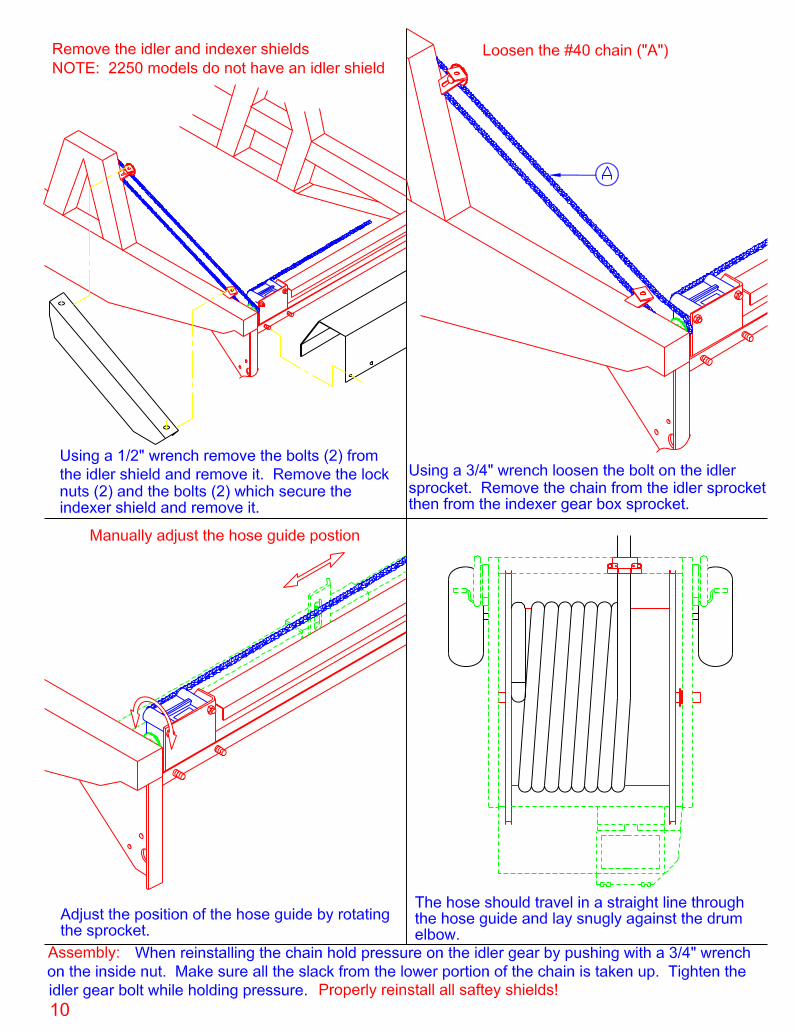
• Remove the indexer shield.• Remove the # 40 chain which runs from the hose drum axle to the indexer gearbox.• Manually adjust the hose guide position so that the hose travels in a straight line
through the hose guide and lays snuggly against the drum elbow.• Re-install the # 40 chain from the hose drum axle to the indexer gearbox.• Re-install the indexer shield.
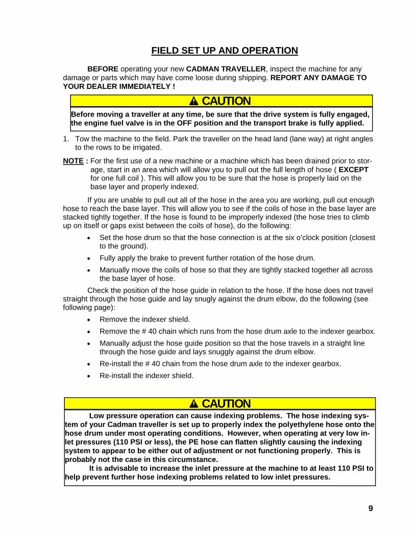
CAUTIONBefore moving a traveller at any time, be sure that the drive system is fully engaged,the engine fuel valve is in the OFF position and the transport brake is fully applied.
CAUTIONLow pressure operation can cause indexing problems. The hose indexing sys-
tem of your Cadman traveller is set up to properly index the polyethylene hose onto thehose drum under most operating conditions. However, when operating at very low in-let pressures (110 PSI or less), the PE hose can flatten slightly causing the indexingsystem to appear to be either out of adjustment or not functioning properly. This isprobably not the case in this circumstance.
It is advisable to increase the inlet pressure at the machine to at least 110 PSI tohelp prevent further hose indexing problems related to low inlet pressures.
11
2 Adjust the tongue jack for a level frame position during operation.
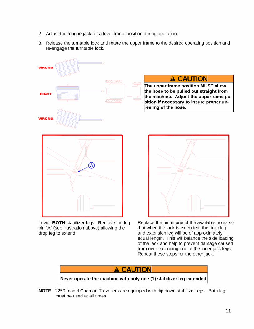
3 Release the turntable lock and rotate the upper frame to the desired operating position andre-engage the turntable lock.
NOTE: 2250 model Cadman Travellers are equipped with flip down stabilizer legs. Both legsmust be used at all times.
A
WRONG
RIGHT
WRONG
CAUTIONThe upper frame position MUST allowthe hose to be pulled out straight fromthe machine. Adjust the upperframe po-sition if necessary to insure proper un-reeling of the hose.
CAUTIONNever operate the machine with only one (1) stabilizer leg extended
Lower BOTH stabilizer legs. Remove the legpin “A” (see illustration above) allowing thedrop leg to extend.
Replace the pin in one of the available holes sothat when the jack is extended, the drop legand extension leg will be of approximatelyequal length. This will balance the side loadingof the jack and help to prevent damage causedfrom over-extending one of the inner jack legs.Repeat these steps for the other jack.

12
5 Shift the transmission lever to the disengageposition (arrow).
6 Adjust the brake handle position so that a slightamount of brake tension is applied. This tension should be enough to control the hosedrum and prevent loosening of the hose on the drum when the tractor stops pulling thehose.
7 Set the track width of the gun cart as wide as possible. Lower the cart to the ground byoperating the hand winch on the side of the machine. Disconnect the lift chain from thecart.
8 Move the tractor from the front of the machine, position it behind the gun cart and attachthe gun cart tow chain to the tractor drawbar.
9 Pull the desired amount of hose. (see illustrationon pg. 11)
10 At this time, set the part circle stops on the gun.The gun should be set behind the cart so that thetravel path remains dry until the cart passes.(see illustration)
210° - 270°
CAUTIONDO NOT exceed 3 MPH while pulling out the hoseDO NOT stop suddenly at the end of your travel lane. Slow gradually when nearing theend of the pull.ALWAYS leave at least a 3/4 wrap of hose on the drum.
WARNINGIf a rear pull is needed, provisions MUST be made to leave the tractor attached to thetongue of hte machine. The tractor must be left in gear and the parking brake ingaged.This provides extra anchoring in addition to the stabilizer legs during the retrieve cycle.
DRIVE SYSTEM DISCONNECTENGAGEDISENGAGE

13
11 Check the nozzle size and checkthat the nozzle cone is secure.
12 Remove the tractor from the gun cart and clear the area of operation.
13 Connect the feeder hose to the inlet on the traveller and lock it in place. Attach the otherend to the mainline or mainline valve.
14 If the hose is loose on the drum, use the hand crank to rotate the drum to tighten the hose.Insure that the hose coils are stacked tightly together.
15 Adjust the brake handle to the full “ON” position after insuring that the hose is tight.
16 GRADUAL pressurization of the system may now begin. Keep the pressure low (under 50PSI) until ALL the air is purged from the system and a steady stream is flowing from the gunnozzle. AFTER all the air is purged from the system, pressure may be slowly raised to amaximum of 150 PSI at the inlet of the machine.
NOTE: Ideally, operating pressures at the inlet will be between 120 PSI and 150 PSI. This will allow gun pressures ranging from approximately 50 PSI to 110 PSI (depending on nozzle size, hose size and length). Assuming proper nozzle selection has been made
based on the pressure and flow volume available, proper droplet sizing and proper gun action, an even and uniform watering pattern will result.
17 Check the mainline and inlet elbow connections.
START UP OF THE RETRIEVE CYCLE
1 Check the engine oil and fuel levels.2 Open the fuel valve on the engine, move the ON / OFF switch to the “ON” position and start
the engine.NOTE: If after several attempts, the engine fails to start, check the shut off bar at the opposite end of the
machine to insure that BOTH shut off switches are depressed. The engine WILL NOT START ifeither switch is released.
WARNINGNever leave the hand crank on the driveshaft. REMOVE IT IMMEDIATELY after use.
CAUTIONOperation of the machine with the inlet pressure below 110 PSI will allow the hose to flattenslightly as it is rewound during the retrieve cycle. This flattening may cause the hose to lay im-properly on the hose drum or make it impossible for all the hose to be rewound. In either case,the hose must be pulled out to correct the problem. If you are unable to provide a minimum of110 PSI to the inlet of the machine contact your dealer for help in improving your system design.
MODEL NOZZLE SIZE
2250 0.77”, 0.81” or 0.86”
2625 0.81”, 0.86”, 0.89” or 0.93”
3000S 1.18” or 1.26”
NOTE: Several nozzle sizes are supplied with the sprinkler gun. The “best” nozzle choice for your application may take some experimentation to determine. Typically, two nozzle sizes will perform well for each model. See the chart below for nozzles to try.
14
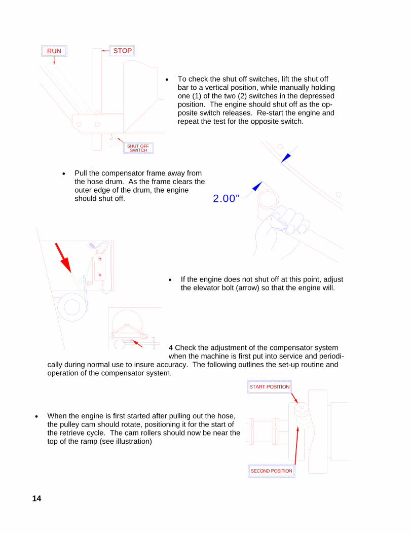
4 Check the adjustment of the compensator systemwhen the machine is first put into service and periodi-
cally during normal use to insure accuracy. The following outlines the set-up routine andoperation of the compensator system.
• When the engine is first started after pulling out the hose,the pulley cam should rotate, positioning it for the start ofthe retrieve cycle. The cam rollers should now be near thetop of the ramp (see illustration)
START POSITION
SECOND POSITION
RUN STOP
SHUT OFFSWITCH
• To check the shut off switches, lift the shut offbar to a vertical position, while manually holdingone (1) of the two (2) switches in the depressedposition. The engine should shut off as the op-posite switch releases. Re-start the engine andrepeat the test for the opposite switch.
• Pull the compensator frame away fromthe hose drum. As the frame clears theouter edge of the drum, the engineshould shut off. 2.00"
• If the engine does not shut off at this point, adjustthe elevator bolt (arrow) so that the engine will.

15
5 Select a retrieve rate to achieve the desired applicationrate. (see example on pg. 16)
• Determine the precipitation amount you require in inches.
• In the gun performance chart, pg. 16, find the gallons per minute you are pumping bycrossing your nozzle size with the pressure you have at the gun.
• From the “TIME REQUIRED TO WATER ONE (1) ACRE” chart (chart #4, pg. 17), find thetime required to cover one (1) acre by crossing your GPM (from the previous step) withyour desired application amount.
• In the “HOSE RETRIEVE RATE” chart (chart #5, pg. 17), find the required hose retrieverate by crossing the “TIME REQUIRED” (from the previous step) with the lane spacing youare using.
6 With the engine running adjust the pulley control knob until the speedometer reads therequired retrieve rate (from step #5)
The control knob should maintain its position when released. If the control knob posi-tion changes on its own, an increase in drag on the control stem may be gained by tighteningthe drag adjustment screw (arrow “A”, top illustration).
As the hose is un-spooled to prepare for thenext irrigation cycle, the compensator frame will followthe hose level. At this time, the compensator controlcable, the cable drive arm, and the pulley cam do notmove (the engine pulley cannot close against the drivebelt). As soon as the engine is started, the reset springwill cause the pulley cam to return to its’ “START” posi-tion (at the top of the cam ramp). If the cam does notreposition properly it can be adjusted. This is accom-plished by changing the length of the push-rod.
Push-rod Stop
THIRD POSITION
FINAL POSITION
A
During the hose retrieve cycle, the compensatorframe rests against the hose on the drum. As each layer ofhose is rewound, the compensator frame moves outward withthe hose. This movement causes the pulley cam to rotate ameasured amount, allowing the pulley to open slightly. Thischanges the diameter of the pulley. The change in pulley di-ameter changes the overall drive ratio which keeps the hoseretrieve rate constant (compensating for the increase in netdrum diameter). This process repeats for each layer of hose.
CAUTIONDO NOT adjust the pulley control knob unless the engine is running. Permanent damageto the pulley may result.
16
NOTE: The speedometer reads actual hose speed ONLY on the base (1st) layer of hose. If the retrieve rate is set or checked on the second, third, or fourth layer, the desired retrieve rate must be set to the “corrected value” for the layer being loaded. This is easily done by referring to the chart attached to the machine next to the speedometer. This “corrected value” is read directly from the speedometer.
(eg.): The desired retrieve rate is 30 inches per minute. The hose is on the second layer when the speed is set. On the SPEED CONVERSION CHART, find 30 inches per minute in the line labeled BASE LAYER. Read the corrected speed value on the 2ND LAYER line in the 30 inches per minute column. Set the speed so the speedometer reeds this corrected value (27). The actual hose speed will be 30 inches per minute
If you are unsure of your retrieve rate for any reason, manually check the retrieve rate by measuring the hose movement over a three (3) minute period and average this measurement (divide by 3).
7. Shift the transmission lever to engage the drive system.
8. Fully release the brake.
9. Make a thorough visual inspection of the of the machine’s function to insure proper operation.
EXAMPLE OF RETRIEVE RATE SELECTION Determine the retrieve rate required to apply a 0.75” application to a field 200 feet in width.
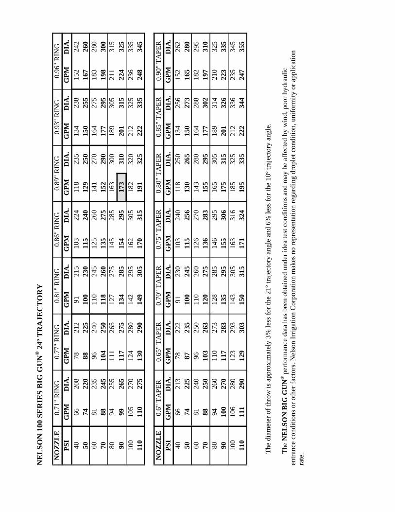
A 2625 model traveller is fitted with a Nelson SR-100 gun. The gun has a 0.89” ring nozzle operating at 90 PSI.
• From the Nelson gun chart, find the GPM you are pumping under the nozzle size you have in the gun. The shaded block under the 0.89” ring nozzle column tells you that the gun is flowing 173 GPM.
• From chart #4, determine how long it should take to cover one (1) acre, in minutes, by crossing the GPM (from above) by the required application of 0.75”. The shaded block tells you that it should take 120 minutes to cover one (1) acre.
• From chart #5, determine the retrieve rate you need to obtain the desired application of 0.75” by crossing the time required to cover one acre (120 minutes) by the lane spacing (200 feet). The shaded block tells you to set the hose retrieve rate at 21 inches per minute as a starting point.
• The gun should be set up so that the 200 foot width is covered plus sufficient overlap (beyond the edge of the crop) to provide adequate watering at the edge of the field.
NOTE: Keep in mind that the charts are to be used as a guide only. Always check the
actual application amount with rain gauges to confirm that the application amount is correct.
NE
LSO
N 1
00 S
ER
IES
BIG
GU
N® 2
4º T
RA
JEC
TO
RY
NO
ZZL
E0.
71" R
ING
0.77
" RIN
G0.
81" R
ING
0.86
" RIN
G0.
89" R
ING
0.93
" RIN
G0.
96" R
ING
PSI
GPM
DIA
.G
PMD
IA.
GPM
DIA
.G
PMD
IA.
GPM
DIA
.G
PMD
IA.
GPM
DIA
.40
6620
878
212
9121
510
322
411
823
513
423
815
224
250
7422
088
225
100
230
115
240
129
250
150
255
167
260
6081
235
9624
011
024
512
526
014
127
016
427
518
328
070
8824
510
425
011
826
013
527
515
229
017
729
519
830
080
9425
511
126
512
727
514
528
516
330
018
930
521
131
590
9926
511
727
513
428
515
429
517
331
020
131
522
432
510
010
527
012
428
014
229
516
230
518
232
021
232
523
633
511
011
027
513
029
014
930
517
031
519
132
522
233
524
834
5
NO
ZZL
E0.
6" T
APE
R0.
65" T
APE
R0.
70" T
APE
R0.
75" T
APE
R0.
80" T
APE
R0.
85" T
APE
R0.
90" T
APE
RPS
IG
PMD
IA.
GPM
DIA
.G
PMD
IA.
GPM
DIA
.G
PMD
IA.
GPM
DIA
.G
PMD
IA.
4066
213
7822
291
230
103
240
118
250
134
256
152
262
5074
225
8723
510
024
511
525
613
026
515
027
316
528
060
8124
096
250
110
260
126
270
143
280
164
288
182
295
7088
250
103
263
120
275
136
283
155
295
177
302
197
310
8094
260
110
273
128
285
146
295
165
305
189
314
210
325
9010
027
011
728
313
529
515
530
617
531
520
132
622
333
510
010
628
012
329
314
330
516
331
618
532
521
233
623
534
511
011
129
012
930
315
031
517
132
419
533
522
234
424
735
5
Th
e di
amet
er o
f thr
ow is
app
roxi
mat
ely
3% le
ss fo
r the
21º
traj
ecto
ry a
ngle
and
6%
less
for t
he 1
8º tr
ajec
tory
ang
le.
Th
e N
EL
SON
BIG
GU
N® p
erfo
rman
ce d
ata
has b
een
obta
ined
und
er id
ea te
st c
ondi
tions
and
may
be
affe
cted
by
win
d, p
oor h
ydra
ulic
en
tranc
e co
nditi
ons o
r oth
er fa
ctor
s. N
elso
n Ir
rigat
ion
Cor
pora
tion
mak
es n
o re
pres
enta
tion
rega
rdin
g dr
ople
t con
ditio
n, u
nifo
rmity
or a
pplic
atio
n ra
te.
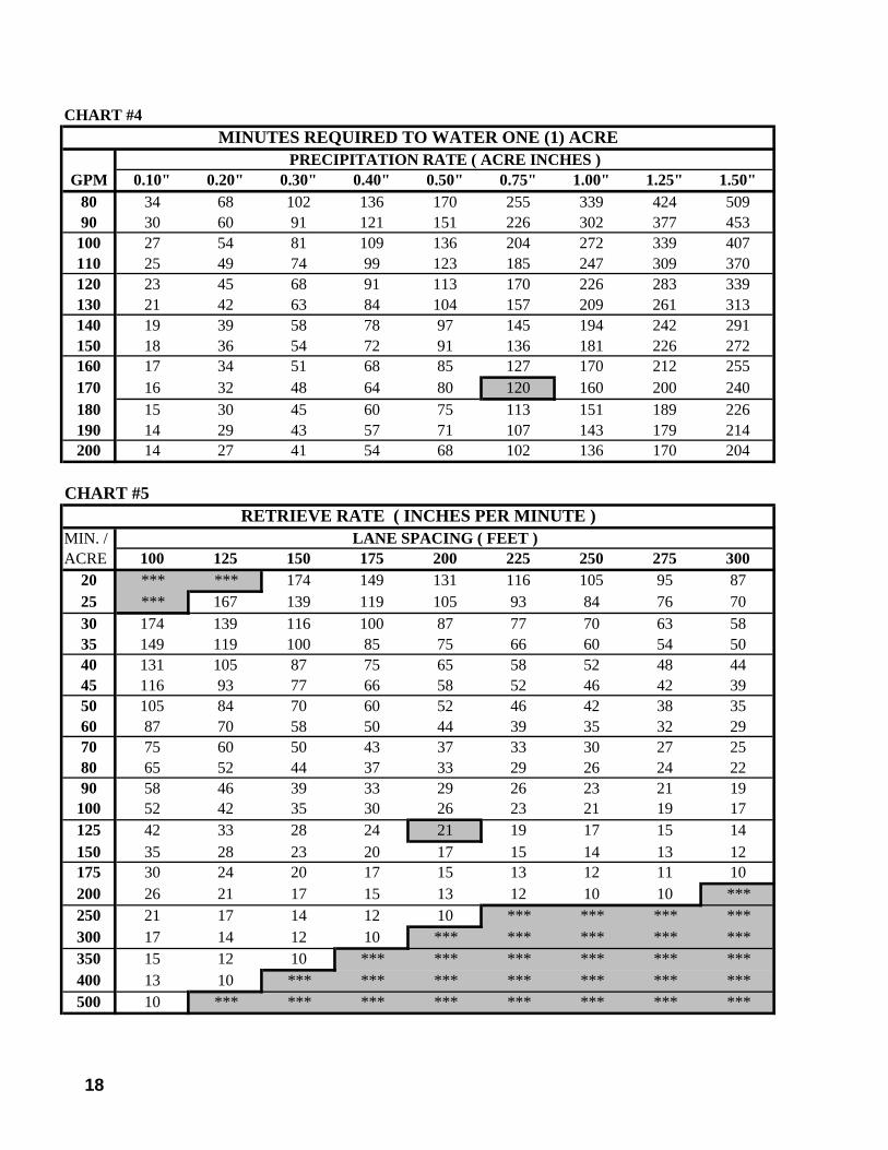
CHART #4MINUTES REQUIRED TO WATER ONE (1) ACRE
PRECIPITATION RATE ( ACRE INCHES )GPM 0.10" 0.20" 0.30" 0.40" 0.50" 0.75" 1.00" 1.25" 1.50"
80 34 68 102 136 170 255 339 424 50990 30 60 91 121 151 226 302 377 453
100 27 54 81 109 136 204 272 339 407110 25 49 74 99 123 185 247 309 370120 23 45 68 91 113 170 226 283 339130 21 42 63 84 104 157 209 261 313140 19 39 58 78 97 145 194 242 291150 18 36 54 72 91 136 181 226 272160 17 34 51 68 85 127 170 212 255170 16 32 48 64 80 120 160 200 240180 15 30 45 60 75 113 151 189 226190 14 29 43 57 71 107 143 179 214200 14 27 41 54 68 102 136 170 204
CHART #5RETRIEVE RATE ( INCHES PER MINUTE )
MIN. / LANE SPACING ( FEET )ACRE 100 125 150 175 200 225 250 275 300
20 *** *** 174 149 131 116 105 95 8725 *** 167 139 119 105 93 84 76 7030 174 139 116 100 87 77 70 63 5835 149 119 100 85 75 66 60 54 5040 131 105 87 75 65 58 52 48 4445 116 93 77 66 58 52 46 42 3950 105 84 70 60 52 46 42 38 3560 87 70 58 50 44 39 35 32 2970 75 60 50 43 37 33 30 27 2580 65 52 44 37 33 29 26 24 2290 58 46 39 33 29 26 23 21 19
100 52 42 35 30 26 23 21 19 17125 42 33 28 24 21 19 17 15 14150 35 28 23 20 17 15 14 13 12175 30 24 20 17 15 13 12 11 10200 26 21 17 15 13 12 10 10 ***250 21 17 14 12 10 *** *** *** ***300 17 14 12 10 *** *** *** *** ***350 15 12 10 *** *** *** *** *** ***400 13 10 *** *** *** *** *** *** ***500 10 *** *** *** *** *** *** *** ***
18
19
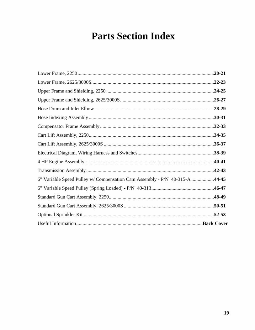
Parts Section Index
Lower Frame, 2250.............................................................................................................20-21
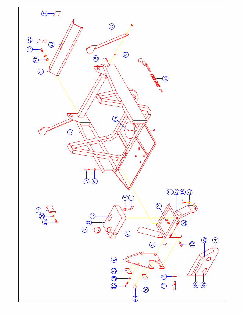
Lower Frame, 2625/3000S..................................................................................................22-23
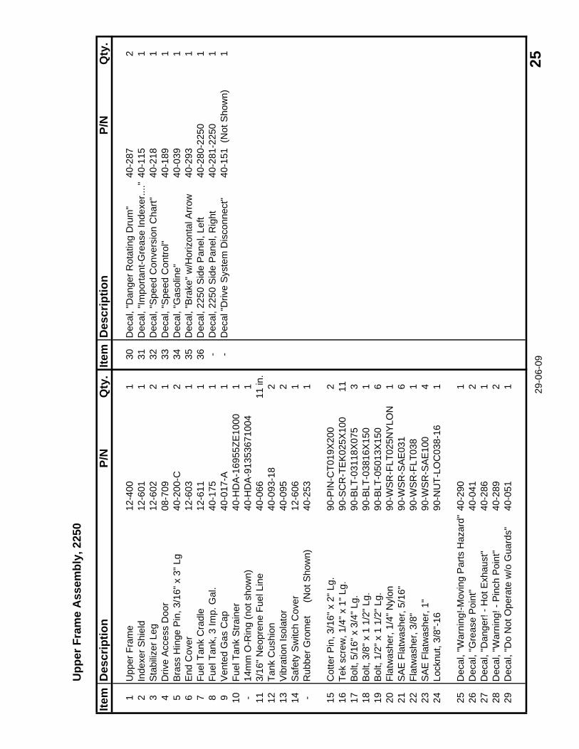
Upper Frame and Shielding, 2250 ......................................................................................24-25
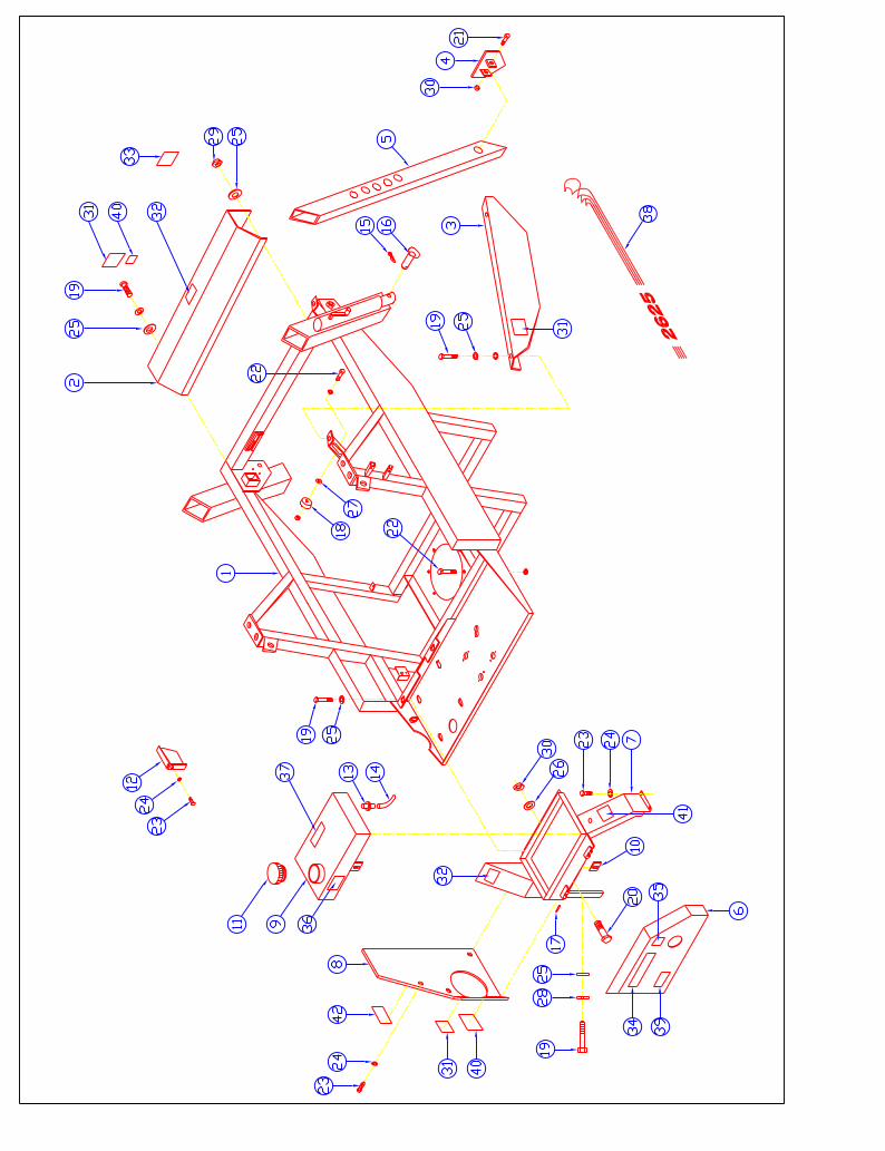
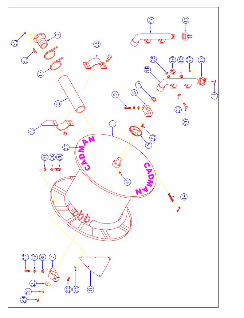
Upper Frame and Shielding, 2625/3000S...........................................................................26-27
Hose Drum and Inlet Elbow ...............................................................................................28-29
Hose Indexing Assembly ....................................................................................................30-31
Compensator Frame Assembly ...........................................................................................32-33
Cart Lift Assembly, 2250....................................................................................................34-35
Cart Lift Assembly, 2625/3000S ........................................................................................36-37
Electrical Diagram, Wiring Harness and Switches.............................................................38-39
4 HP Engine Assembly .......................................................................................................40-41
Transmission Assembly ......................................................................................................42-43
6” Variable Speed Pulley w/ Compensation Cam Assembly - P/N 40-315-A ..................44-45
6” Variable Speed Pulley (Spring Loaded) - P/N 40-313..................................................46-47
Standard Gun Cart Assembly, 2250....................................................................................48-49
Standard Gun Cart Assembly, 2625/3000S ........................................................................50-51
Optional Sprinkler Kit ........................................................................................................52-53
Useful Information.....................................................................................................Back Cover
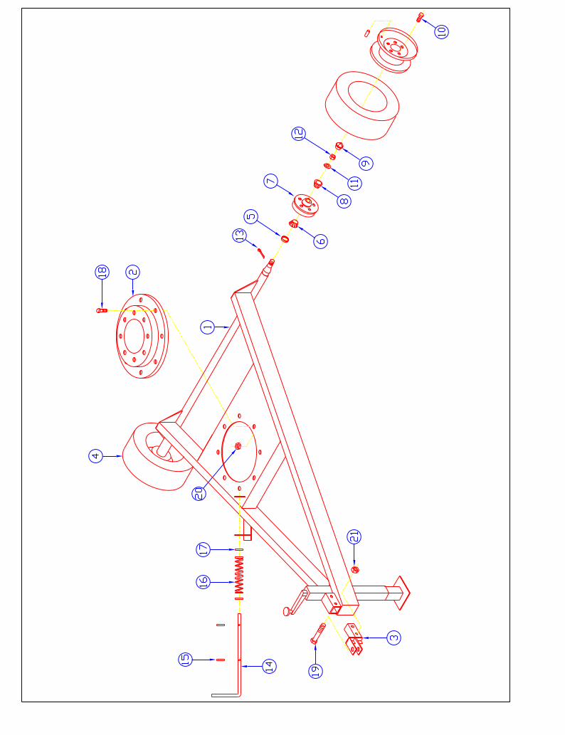
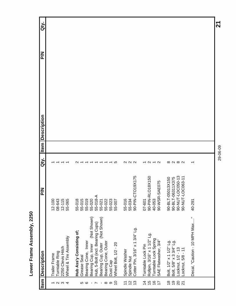
Low
er F
ram
e A
ssem
bly,
225
0
Item
Des
crip
tion
P/N
Qty
.Ite
mD
escr
iptio
nP/
NQ
ty.
1Tr
aile
r Fra
me
12-1
001
2Tu
rnta
ble
Rin
g08
-643
13
2250
Cle
vis
Hitc
h12
-115
14
Whe
el &
Tire
Ass
embl
y55
-065
1
Hub
Ass
'y C
onsi
stin
g of
;55
-018
25
Gre
ase
Sea
l55
-015
16
Bea
ring
Con
e, I
nner
55-0
191
-B
earin
g C
up, I
nner
(
Not
Sho
wn)
55-0
201
7H
ub, 5
-Bol
t (in
cl. B
earin
g C
ups)
55-0
18-A
1-
Bea
ring
Cup
, Out
er
(Not
Sho
wn)
55-0
211
8B
earin
g C
one,
Out
er55
-022
19
Dus
t Cap
55-0
231
10W
heel
Bol
t, 1/
2 - 2
055
-007
5
11S
pind
le W
ashe
r55
-016
212
Spi
ndle
Nut
55-0
342
13C
otte
r Pin
, 3/1
6" x
1 3
/4" L
g.90
-PIN
-CTO
19X
175
2
14Tu
rnta
ble
Lock
Pin
07-6
011
15R
ollp
in, 3
/16"
x 1
1/2
" Lg.
90-P
IN-R
LO18
X15
02
16Tu
rnta
ble
Lock
Spr
ing
40-0
531
17S
AE
Fla
twas
her,
3/4"
90-W
SR
-SA
E07
52
18B
olt,
1/2"
x 1
1/2
" Lg.
90-B
LT-0
5013
X15
08
19B
olt,
5/8"
x 3
3/4
" Lg.
90-B
LT-0
6311
X37
52
20Lo
cknu
t, 1/
2 - 1
390
-NU
T-LO
C05
0-13
821
Lock
nut,
5/8
- 11
90-N
UT-
LOC
063-
112
Dec
al, "
Cau
tion
- 10
MP
H M
ax…
."40
-291
1 29-0
6-09
21
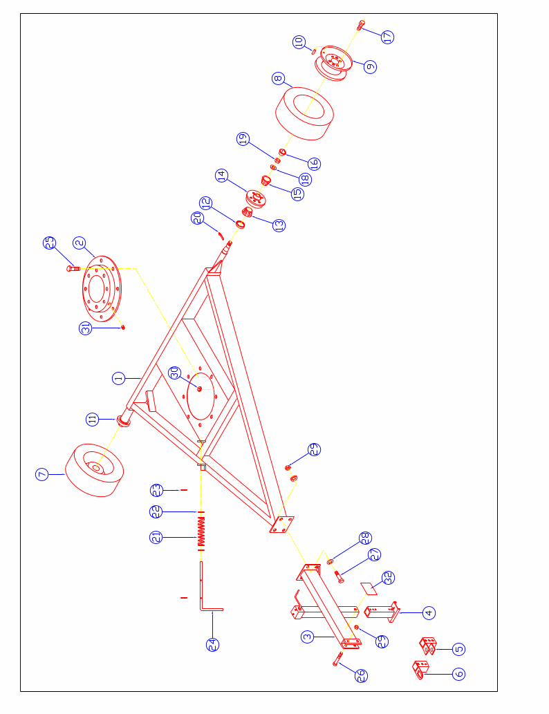
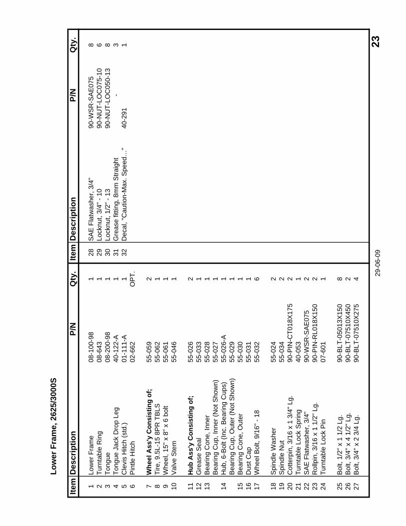
Low
er F
ram
e, 2
625/
3000
S
Item
Des
crip
tion
P/N
Qty
.Ite
mD
escr
iptio
nP/
NQ
ty.
1Lo
wer
Fra
me
08-1
00-9
81
28S
AE
Fla
twas
her,
3/4"
90-W
SR
-SA
E07
58
2Tu
rnta
ble
Rin
g08
-643
129
Lock
nut,
3/4"
- 10
90-N
UT-
LOC
075-
106
3To
ngue
08-2
00-9
81
30Lo
cknu
t, 1/
2" -
1390
-NU
T-LO
C05
0-13
84
Tong
ue J
ack
Dro
p Le
g40
-122
-A1
31G
reas
e fit
ting,
8m
m S
traig
ht-
35
Cle
vis
Hitc
h (s
td.)
01-1
11-A
132
Dec
al, "
Cau
tion-
Max
. Spe
ed…
"40
-291
16
Pin
tle H
itch
02-6
62O
PT.
7W
heel
Ass
'y C
onsi
stin
g of
;55
-059
28
Tire
, 9.5
L-15
8P
R T
BLS
55
-062
19
Whe
el, 1
5" x
8" x
6 b
olt
55-0
611
10V
alve
Ste
m55
-046
1
11H
ub A
ss'y
Con
sist
ing
of;
55-0
262
12G
reas
e S
eal
55-0
331
13B
earin
g C
one,
Inne
r55
-028
1B
earin
g C
up, I
nner
(Not
Sho
wn)
55-0
271
14H
ub, 6
-Bol
t (In
c. B
earin
g C
ups)
55-0
26-A
1B
earin
g C
up, O
uter
(Not
Sho
wn)
55-0
291
15B
earin
g C
one,
Out
er55
-030
116
Dus
t Cap
55-0
311
17W
heel
Bol
t, 9/
16" -
18
55-0
326
18S
pind
le W
ashe
r55
-024
219
Spi
ndle
Nut
55-0
342
20C
otte
rpin
, 3/1
6 x
1 3/
4" L
g.90
-PIN
-CT0
18X
175
221
Turn
tabl
e Lo
ck S
prin
g40
-053
122
SA
E F
latw
ashe
r, 3/
4"90
-WS
R-S
AE
075
223
Rol
lpin
, 3/1
6 x
1 1/
2" L
g.90
-PIN
-RL0
18X
150
224
Turn
tabl
e Lo
ck P
in07
-601
1
25B
olt,
1/2"
x 1
1/2
Lg.
90-B
LT-0
5013
X15
08
26B
olt,
3/4"
x 4
1/2
" Lg.
90-B
LT-0
7510
X45
02
27B
olt,
3/4"
x 2
3/4
Lg.
90-B
LT-0
7510
X27
54 29
-06-
09 2
3
Upp
er F
ram
e A
ssem
bly,
225
0
Item
Des
crip
tion
P/N
Qty
.Ite
mD
escr
iptio
nP/
NQ
ty.
1U
pper
Fra
me
12-4
001
30D
ecal
, "D
ange
r Rot
atin
g D
rum
"40
-287
22
Inde
xer S
hiel
d12
-601
131
Dec
al, "
Impo
rtant
-Gre
ase
Inde
xer..
.."40
-115
13
Sta
biliz
er L
eg12
-602
232
Dec
al, "
Spe
ed C
onve
rsio
n C
hart"
40-2
181
4D
rive
Acc
ess
Doo
r08
-709
133
Dec
al, "
Spe
ed C
ontro
l"40
-189
15
Bra
ss H
inge
Pin
, 3/1
6" x
3" L
g40
-200
-C2
34D
ecal
, "G
asol
ine"
40-0
391
6E
nd C
over
12-6
031
35D
ecal
, "B
rake
" w/H
oriz
onta
l Arr
ow40
-293
17
Fuel
Tan
k C
radl
e12
-611
136
Dec
al, 2
250
Sid
e P
anel
, Lef
t40
-280
-225
01
8Fu
el T
ank,
3 Im
p. G
al.
40-1
751
-D
ecal
, 225
0 S
ide
Pan
el, R
ight
40-2
81-2
250
19
Ven
ted
Gas
Cap
40-0
17-A
1-
Dec
al "D
rive
Sys
tem
Dis
conn
ect"
40-1
51 (
Not
Sho
wn)
110
Fuel
Tan
k S
train
er40
-HD
A-1
6955
ZE10
001
-14
mm
O-R
ing
(not
sho
wn)
40-H
DA
-913
5367
1004
111
3/16
" Neo
pren
e Fu
el L
ine
40-0
6611
in.
12Ta
nk C
ushi
on40
-093
-18
213
Vib
ratio
n Is
olat
or40
-095
214
Saf
ety
Sw
itch
Cov
er12
-606
1-
Rub
ber G
rom
et
(N
ot S
how
n)40
-253
1
15C
otte
r Pin
, 3/1
6" x
2" L
g.90
-PIN
-CT0
19X
200
216
Tek
scre
w, 1
/4" x
1" L
g.90
-SC
R-T
EK
025X
100
1117
Bol
t, 5/
16" x
3/4
" Lg.
90-B
LT-0
3118
X07
53
18B
olt,
3/8"
x 1
1/2
" Lg.
90-B
LT-0
3816
X15
01
19B
olt,
1/2"
x 1
1/2
" Lg.
90-B
LT-0
5013
X15
06
20Fl
atw
ashe
r, 1/
4" N
ylon
90-W
SR
-FLT
025N
YLO
N1
21S
AE
Fla
twas
her,
5/16
"90
-WS
R-S
AE
031
622
Flat
was
her,
3/8"
90
-WS
R-F
LT03
81
23S
AE
Fla
twas
her,
1"90
-WS
R-S
AE
100
424
Lock
nut,
3/8"
-16
90-N
UT-
LOC
038-
161
25D
ecal
, "W
arni
ng!-M
ovin
g P
arts
Haz
ard"
40-2
901
26D
ecal
, "G
reas
e P
oint
"40
-041
227
Dec
al, "
Dan
ger!
- Hot
Exh
aust
"40
-286
128
Dec
al, "
War
ning
! - P
inch
Poi
nt"
40-2
892
29D
ecal
, "D
o N
ot O
pera
te w
/o G
uard
s"40
-051
1 29-0
6-09
25
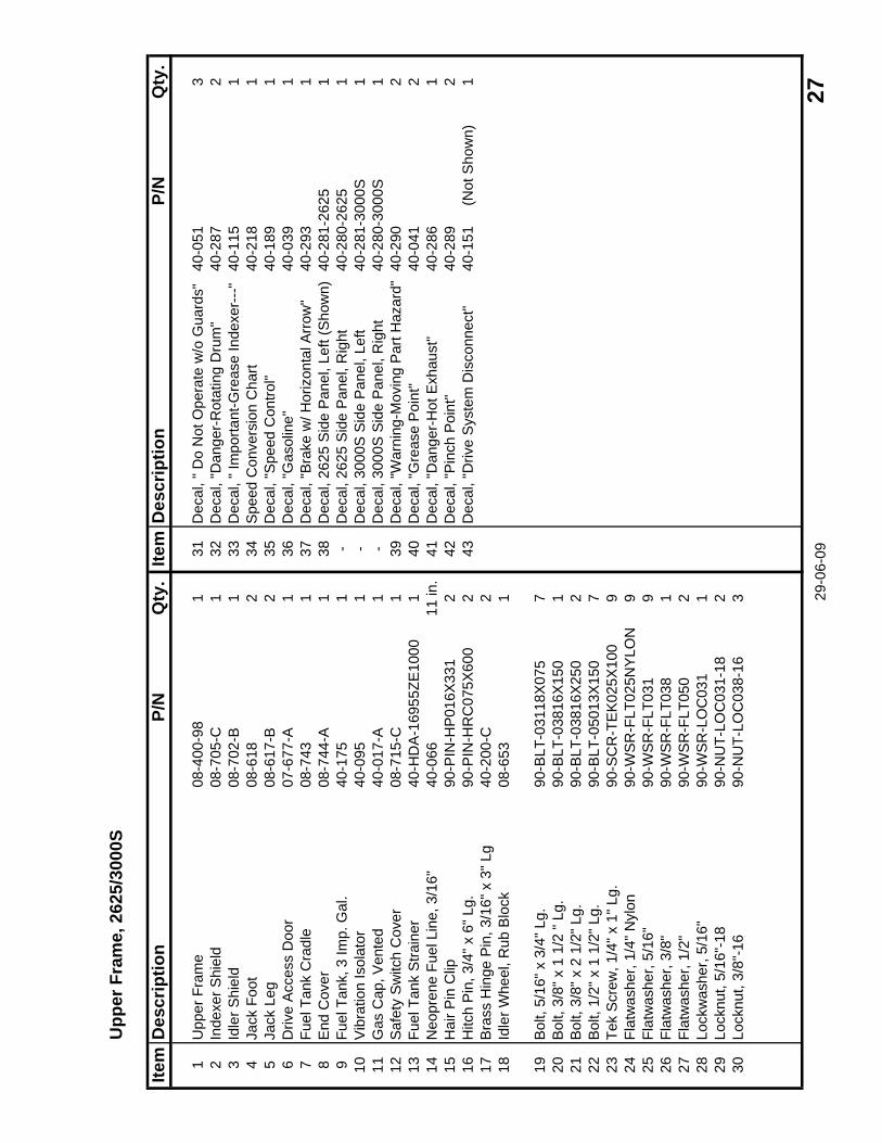
Upp
er F
ram
e, 2
625/
3000
S
Item
Des
crip
tion
P/N
Qty
.Ite
mD
escr
iptio
nP/
NQ
ty.
1U
pper
Fra
me
08-4
00-9
81
31D
ecal
, " D
o N
ot O
pera
te w
/o G
uard
s"40
-051
32
Inde
xer S
hiel
d08
-705
-C1
32D
ecal
, "D
ange
r-R
otat
ing
Dru
m"
40-2
872
3Id
ler S
hiel
d08
-702
-B1
33D
ecal
, " Im
porta
nt-G
reas
e In
dexe
r---
"40
-115
14
Jack
Foo
t08
-618
234
Spe
ed C
onve
rsio
n C
hart
40-2
181
5Ja
ck L
eg08
-617
-B2
35D
ecal
, "S
peed
Con
trol"
40-1
891
6D
rive
Acc
ess
Doo
r07
-677
-A1
36D
ecal
, "G
asol
ine"
40-0
391
7Fu
el T
ank
Cra
dle
08-7
431
37D
ecal
, "B
rake
w/ H
oriz
onta
l Arr
ow"
40-2
931
8E
nd C
over
08-7
44-A
138
Dec
al, 2
625
Sid
e P
anel
, Lef
t (S
how
n)40
-281
-262
51
9Fu
el T
ank,
3 Im
p. G
al.
40-1
751
-D
ecal
, 262
5 S
ide
Pan
el, R
ight
40-2
80-2
625
110
Vib
ratio
n Is
olat
or40
-095
1-
Dec
al, 3
000S
Sid
e P
anel
, Lef
t40
-281
-300
0S1
11G
as C
ap, V
ente
d40
-017
-A1
-D
ecal
, 300
0S S
ide
Pan
el, R
ight
40-2
80-3
000S
112
Saf
ety
Sw
itch
Cov
er08
-715
-C1
39D
ecal
, "W
arni
ng-M
ovin
g P
art H
azar
d"40
-290
213
Fuel
Tan
k S
train
er40
-HD
A-1
6955
ZE10
001
40D
ecal
, "G
reas
e P
oint
"40
-041
214
Neo
pren
e Fu
el L
ine,
3/1
6"40
-066
11 in
.41
Dec
al, "
Dan
ger-
Hot
Exh
aust
"40
-286
115
Hai
r Pin
Clip
90-P
IN-H
P01
6X33
12
42D
ecal
, "P
inch
Poi
nt"
40-2
892
16H
itch
Pin
, 3/4
" x 6
" Lg.
90-P
IN-H
RC
075X
600
243
Dec
al, "
Driv
e S
yste
m D
isco
nnec
t"40
-151
(
Not
Sho
wn)
117
Bra
ss H
inge
Pin
, 3/1
6" x
3" L
g40
-200
-C2
18Id
ler W
heel
, Rub
Blo
ck08
-653
1
19B
olt,
5/16
" x 3
/4" L
g.90
-BLT
-031
18X
075
720
Bol
t, 3/
8" x
1 1
/2 "
Lg.
90-B
LT-0
3816
X15
01
21B
olt,
3/8"
x 2
1/2
" Lg.
90-B
LT-0
3816
X25
02
22B
olt,
1/2"
x 1
1/2
" Lg.
90-B
LT-0
5013
X15
07
23Te
k S
crew
, 1/4
" x 1
" Lg.
90-S
CR
-TE
K02
5X10
09
24Fl
atw
ashe
r, 1/
4" N
ylon
90-W
SR
-FLT
025N
YLO
N9
25Fl
atw
ashe
r, 5/
16"
90-W
SR
-FLT
031
926
Flat
was
her,
3/8"
90-W
SR
-FLT
038
127
Flat
was
her,
1/2"
90-W
SR
-FLT
050
228
Lock
was
her,
5/16
"90
-WS
R-L
OC
031
129
Lock
nut,
5/16
"-18
90-N
UT-
LOC
031-
182
30Lo
cknu
t, 3/
8"-1
690
-NU
T-LO
C03
8-16
3 29-0
6-09
27
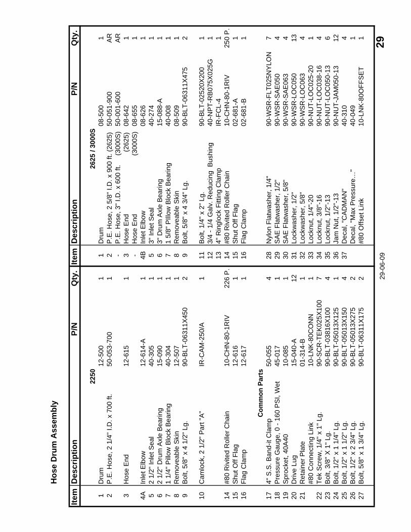
Hos
e D
rum
Ass
embl
y
Item
Des
crip
tion
P/N
Qty
.Ite
mD
escr
iptio
nP/
NQ
ty.
2250
2625
/ 30
00S
1D
rum
12-5
001
1D
rum
08-5
001
2P
.E. H
ose,
2 1
/4" I
.D. x
700
ft.
50-0
53-7
001
2P
.E. H
ose,
2 5
/8" I
.D. x
900
ft. (
2625
)50
-051
-900
AR
-P
.E. H
ose,
3" I
.D. x
600
ft.
(3
000S
)50
-001
-600
AR
3H
ose
End
12-6
151
3H
ose
End
(2
625)
08-6
421
-H
ose
End
(300
0S)
08-6
551
4AIn
let E
lbow
12-6
14-A
14B
Inle
t Elb
ow08
-626
15
2 1/
2" In
let S
eal
40-3
051
53"
Inle
t Sea
l40
-274
16
2 1/
2" D
rum
Axl
e B
earin
g15
-090
16
3" D
rum
Axl
e B
earin
g15
-088
-A1
71
1/4"
Pill
ow B
lock
Bea
ring
40-3
041
71
5/8"
PIll
ow B
lock
Bea
ring
40-0
081
8R
emov
eabl
e S
kin
12-5
071
8R
emov
eabl
e S
kin
08-5
091
9B
olt,
5/8"
x 4
1/2
" Lg.
90-B
LT-0
6311
X45
02
9B
olt,
5/8"
x 4
3/4
" Lg.
90-B
LT-0
6311
X47
52
10C
amlo
ck, 2
1/2
" Par
t "A
"IR
-CA
M-2
50/A
111
Bol
t, 1/
4" x
2" L
g.90
-BLT
-025
20X
200
112
3/4
- 1/4
Gal
v. R
educ
ing
Bus
hing
40-N
PT-
RB
075X
025G
113
4" R
ingl
ock
Fitti
ng C
lam
pIR
-FC
L-4
114
#80
Riv
ited
Rol
ler C
hain
10-C
HN
-80-
1RIV
226
P.
14#8
0 R
ivite
d R
olle
r Cha
in10
-CH
N-8
0-1R
IV25
0 P
.15
Shu
t Off
Flag
12-6
161
15S
hut O
ff Fl
ag02
-681
-A1
16Fl
ag C
lam
p12
-617
116
Flag
Cla
mp
02-6
81-B
1
Com
mon
Par
ts17
4" S
.S. B
and-
it C
lam
p50
-055
428
Nyl
on F
latw
ashe
r, 1/
4"90
-WS
R-F
LT02
5NY
LON
718
Pre
ssur
e G
auge
, 0 -
160
PS
I, W
et45
-017
129
SA
E F
latw
ashe
r, 1/
2"90
-WS
R-S
AE
050
419
Spr
ocke
t, 40
A40
10-0
851
30S
AE
Fla
twas
her,
5/8"
90-W
SR
-SA
E06
34
20D
rive
Lug
15-0
40-A
1231
Lock
was
her,
1/2"
90-W
SR
-LO
C05
013
21R
etai
ner P
late
01-3
14-B
132
Lock
was
her,
5/8"
90
-WS
R-L
OC
063
4#8
0 C
onne
ctin
g Li
nk10
-LN
K-8
0CO
NN
133
Lock
nut,
1/4"
-20
90-N
UT-
LOC
025-
201
22Te
k S
crew
, 1/4
" x 1
" Lg.
90-S
CR
-TE
K02
5X10
07
34Lo
cknu
t, 3/
8"-1
690
-NU
T-LO
C03
8-16
423
Bol
t, 3/
8" X
1" L
g.90
-BLT
-038
16X
100
435
Lock
nut,
1/2"
-13
90-N
UT-
LOC
050-
136
24B
olt,
1/2"
x 1
1/4
" Lg.
90-B
LT-0
5013
X12
51
36Ja
m N
ut, 1
/2"-
1390
-NU
T-JA
M05
0-13
1225
Bol
t, 1/
2" x
1 1
/2" L
g.90
-BLT
-050
13X
150
437
Dec
al, "
CA
DM
AN
"40
-310
426
Bol
t, 1/
2" x
2 3
/4" L
g.90
-BLT
-050
13X
275
2D
ecal
, "M
ax P
ress
ure…
"40
-049
127
Bol
t, 5/
8" x
1 3
/4" L
g.90
-BLT
-063
11X
175
2#8
0 O
ffset
Lin
k10
-LN
K-8
0OFF
SE
T1
29-0
6-09
29
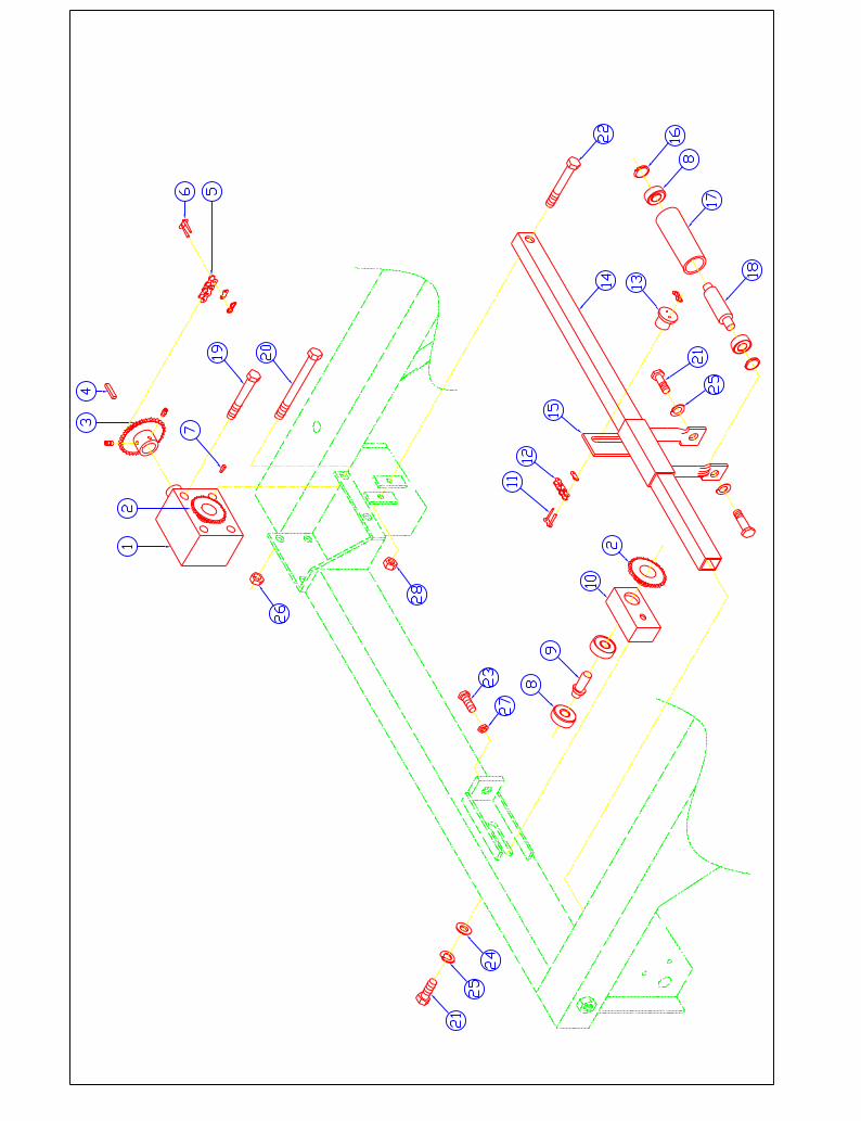
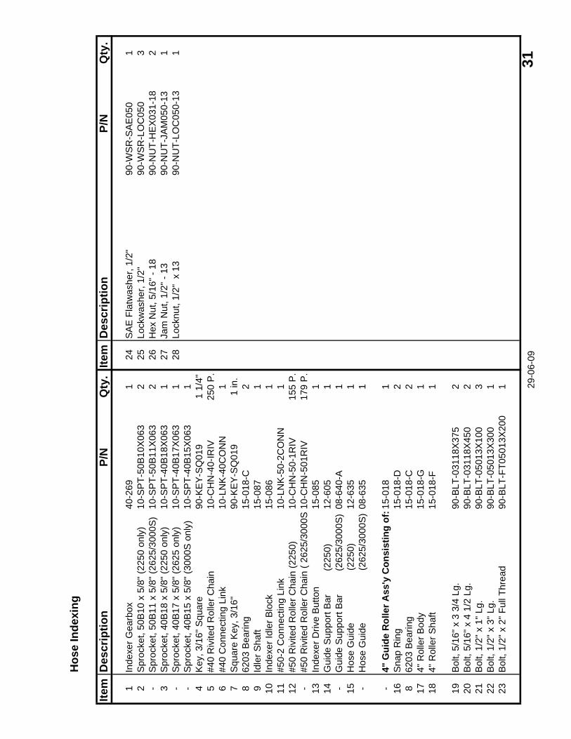
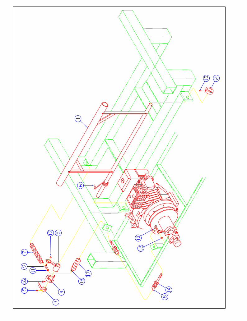
Hos
e In
dexi
ng
Item
Des
crip
tion
P/N
Qty
.Ite
mD
escr
iptio
nP/
NQ
ty.
1In
dexe
r Gea
rbox
40-2
691
24S
AE
Fla
twas
her,
1/2"
90-W
SR
-SA
E05
01
2S
proc
ket,
50B
10 x
5/8
" (22
50 o
nly)
10-S
PT-
50B
10X
063
225
Lock
was
her,
1/2"
90-W
SR
-LO
C05
03
-S
proc
ket,
50B
11 x
5/8
" (26
25/3
000S
)10
-SP
T-50
B11
X06
32
26H
ex N
ut, 5
/16"
- 18
90-N
UT-
HE
X03
1-18
23
Spr
ocke
t, 40
B18
x 5
/8" (
2250
onl
y)10
-SP
T-40
B18
X06
31
27Ja
m N
ut, 1
/2" -
13
90-N
UT-
JAM
050-
131
-S
proc
ket,
40B
17 x
5/8
" (26
25 o
nly)
10-S
PT-
40B
17X
063
128
Lock
nut,
1/2"
x 1
390
-NU
T-LO
C05
0-13
1-
Spr
ocke
t, 40
B15
x 5
/8" (
3000
S o
nly)
10-S
PT-
40B
15X
063
14
Key
, 3/1
6" S
quar
e90
-KE
Y-S
Q01
91
1/4"
5#4
0 R
ivite
d R
olle
r Cha
in10
-CH
N-4
0-IR
IV25
0 P
.6
#40
Con
nect
ing
Link
10-L
NK
-40C
ON
N1
7S
quar
e K
ey, 3
/16"
90-K
EY
-SQ
019
1 in
.8
6203
Bea
ring
15-0
18-C
29
Idle
r Sha
ft15
-087
110
Inde
xer I
dler
Blo
ck15
-086
111
#50-
2 C
onne
ctin
g Li
nk10
-LN
K-5
0-2C
ON
N1
12#5
0 R
ivite
d R
olle
r Cha
in (2
250)
10-C
HN
-50-
1RIV
155
P.
-#5
0 R
ivite
d R
olle
r Cha
in (
2625
/300
0S10
-CH
N-5
01R
IV17
9 P
.13
Inde
xer D
rive
But
ton
15-0
851
14G
uide
Sup
port
Bar
(2
250)
12-6
051
-G
uide
Sup
port
Bar
(2
625/
3000
S)
08-6
40-A
115
Hos
e G
uide
(22
50)
12-6
351
-H
ose
Gui
de
(
2625
/300
0S)
08-6
351
-4"
Gui
de R
olle
r Ass
'y C
onsi
stin
g of
:15-
018
116
Sna
p R
ing
15-0
18-D
28
6203
Bea
ring
15-0
18-C
217
4" R
olle
r Bod
y15
-018
-G1
184"
Rol
ler S
haft
15-0
18-F
1
19B
olt,
5/16
" x 3
3/4
Lg.
90-B
LT-0
3118
X37
52
20B
olt,
5/16
" x 4
1/2
Lg.
90-B
LT-0
3118
X45
02
21B
olt,
1/2"
x 1
" Lg.
90-B
LT-0
5013
X10
03
22B
olt,
1/2"
x 3
" Lg.
90-B
LT-0
5013
X30
01
23B
olt,
1/2"
x 2
" Ful
l Thr
ead
90-B
LT-F
T050
13X
200
1 29-0
6-09
31
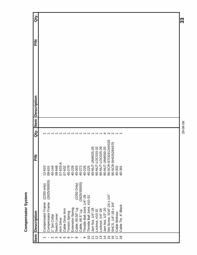
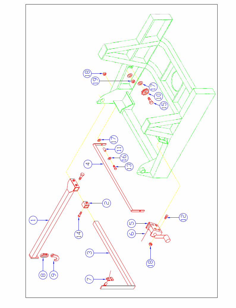
Com
pens
ator
Sys
tem
Item
Des
crip
tion
P/N
Qty
.Ite
mD
escr
iptio
nP/
NQ
ty.
1C
ompe
nsat
or F
ram
e (
2250
onl
y)12
-610
1-
Com
pens
ator
Fra
me
(26
25/3
000S
)08
-631
12
1" S
et C
olla
r40
-144
13
Sw
itch
Leve
r08
-648
14
Arm
Driv
e07
-633
-A1
5C
able
Driv
e A
rm07
-632
16
Tors
ion
Spr
ing
40-2
791
7E
xten
sion
Spr
ing
40-2
281
8C
able
, 60.
50" L
g.
(
2250
Onl
y)40
-303
1-
Cab
le, 6
6.5"
Lg.
(26
25/3
000S
)40
-272
19
Thro
ttle
Bal
l Joi
nt, 1
/4"-
2840
-226
110
Thro
ttle
Bal
l Joi
nt, #
10-3
240
-225
111
Jam
Nut
, 1/4
"-28
90-N
UT-
JAM
025-
281
12Lo
cknu
t, #1
0-32
90-N
UT-
LOC
010-
321
13Lo
cknu
t, 1/
4"-2
890
-NU
T-LO
C02
5-28
114
Jam
Nut
, 1/2
"-20
90-N
UT-
JAM
050-
204
15S
et S
crew
, 5/1
6"-2
4 x
1/4"
90-S
CR
-STO
0312
4X02
52
16S
HC
S, 1
/4"-
28 x
3/4
"90
-SC
R-S
H02
528X
075
217
Cab
le B
ello
ws
40-3
021
18C
able
Tie
, 4" B
lack
40-3
911 29
-06-
09 3
3
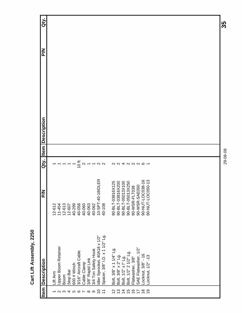
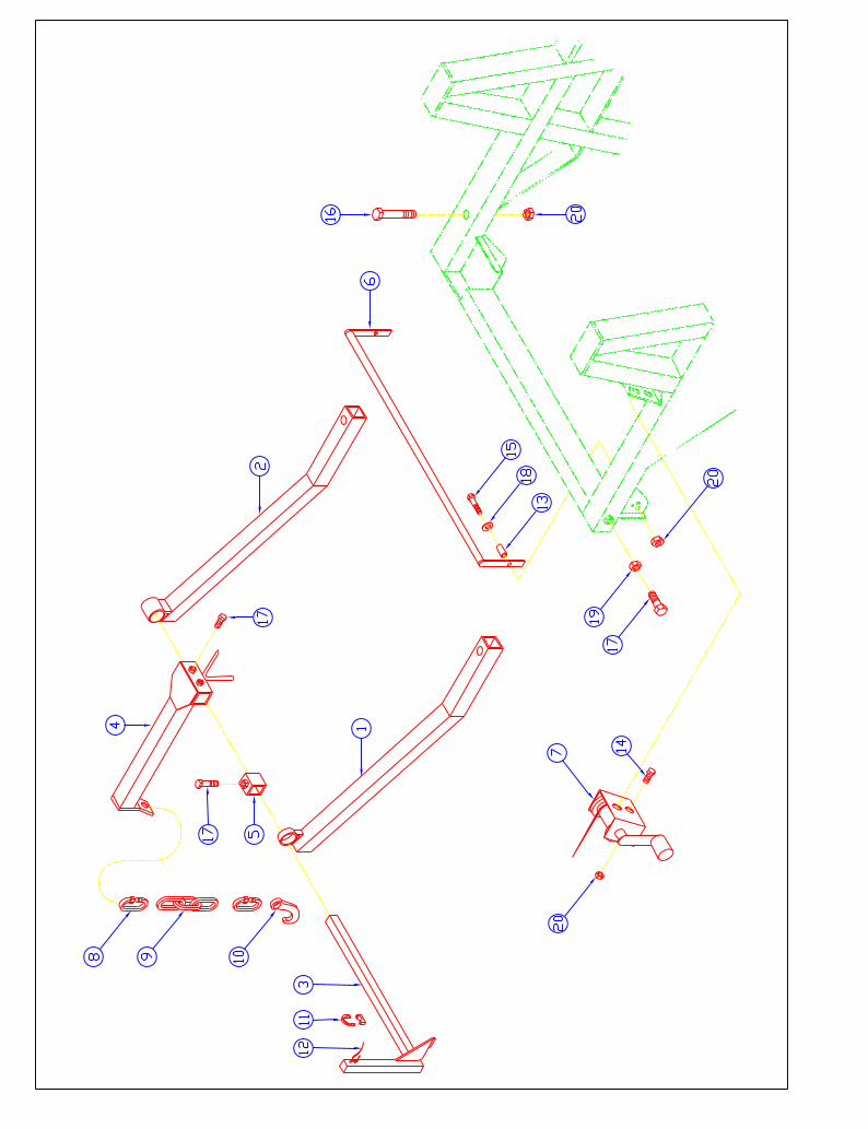
Car
t Lift
Ass
embl
y, 2
250
Item
Des
crip
tion
P/N
Qty
.Ite
mD
escr
iptio
nP/
NQ
ty.
1Li
ft A
rm12
-612
12
Upp
er B
oom
Ret
aine
r11
-454
13
Boo
m12
-613
14
Sto
p B
ar12
-607
15
600
# W
inch
40-2
991
63/
16" A
ircra
ft C
able
40-0
5810
ft.
7C
able
Cla
mp
40-0
602
83/
8" R
apid
Lin
k40
-063
19
3/4
Ton
Saf
ety
Hoo
k40
-062
110
Idle
r Spr
ocke
t, 40
A18
x 1
/2"
10-S
PT-
40-1
8ID
LER
211
Spa
cer,
3/8"
I.D
. x 1
1/2
" Lg.
40-1
082
12B
olt,
3/8"
x 1
1/4
" Lg.
90-B
LT-0
3816
X12
52
13B
olt,
3/8"
x 2
" Lg.
90-B
LT-0
3816
X20
02
14B
olt,
1/2"
x l"
Lg.
90-B
LT-0
5013
X10
04
15B
olt,
1/2"
2 1
/2" L
g.90
-BLT
-050
13X
250
216
Flat
was
her,
3/8"
90-W
SR
-FLT
038
217
SA
E F
latw
ashe
r, 1/
2"90
-WS
R-S
AE
050
218
Lock
nut,
3/8"
- 16
90-N
UT-
LOC
038-
166
19Lo
cknu
t, 1/
2" -1
390
-NU
T-LO
C05
0-13
1 29-0
6-09
35
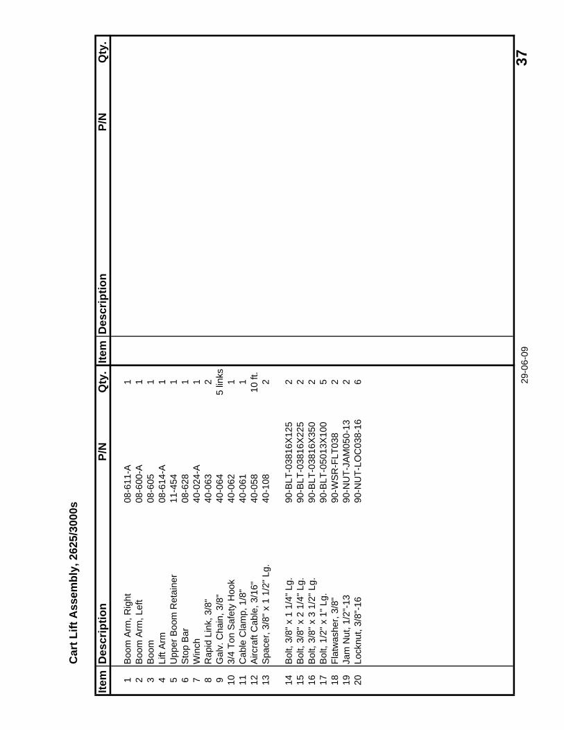
Car
t Lift
Ass
embl
y, 2
625/
3000
s
Item
Des
crip
tion
P/N
Qty
.Ite
mD
escr
iptio
nP/
NQ
ty.
1B
oom
Arm
, Rig
ht08
-611
-A1
2B
oom
Arm
, Lef
t08
-600
-A1
3B
oom
08-6
051
4Li
ft A
rm08
-614
-A1
5U
pper
Boo
m R
etai
ner
11-4
541
6S
top
Bar
08-6
281
7W
inch
40-0
24-A
18
Rap
id L
ink,
3/8
"40
-063
29
Gal
v. C
hain
, 3/8
"40
-064
5 lin
ks10
3/4
Ton
Saf
ety
Hoo
k40
-062
111
Cab
le C
lam
p, 1
/8"
40-0
611
12A
ircra
ft C
able
, 3/1
6"40
-058
10 ft
.13
Spa
cer,
3/8"
x 1
1/2
" Lg.
40-1
082
14B
olt,
3/8"
x 1
1/4
" Lg.
90-B
LT-0
3816
X12
52
15B
olt,
3/8"
x 2
1/4
" Lg.
90-B
LT-0
3816
X22
52
16B
olt,
3/8"
x 3
1/2
" Lg.
90-B
LT-0
3816
X35
02
17B
olt,
1/2"
x 1
" Lg.
90-B
LT-0
5013
X10
05
18Fl
atw
ashe
r, 3/
8"90
-WS
R-F
LT03
82
19Ja
m N
ut, 1
/2"-
1390
-NU
T-JA
M05
0-13
220
Lock
nut,
3/8"
-16
90-N
UT-
LOC
038-
166 29
-06-
09 3
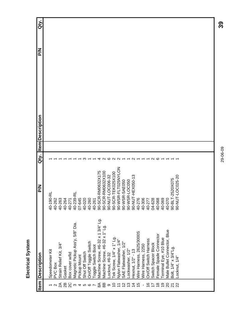
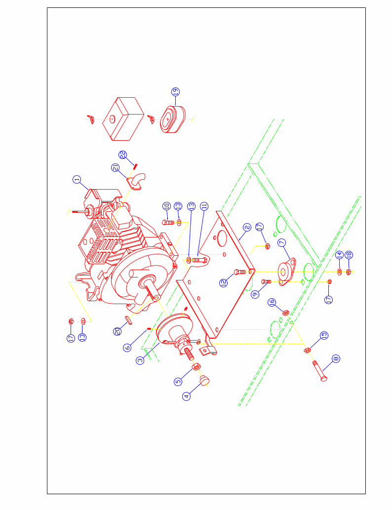
7
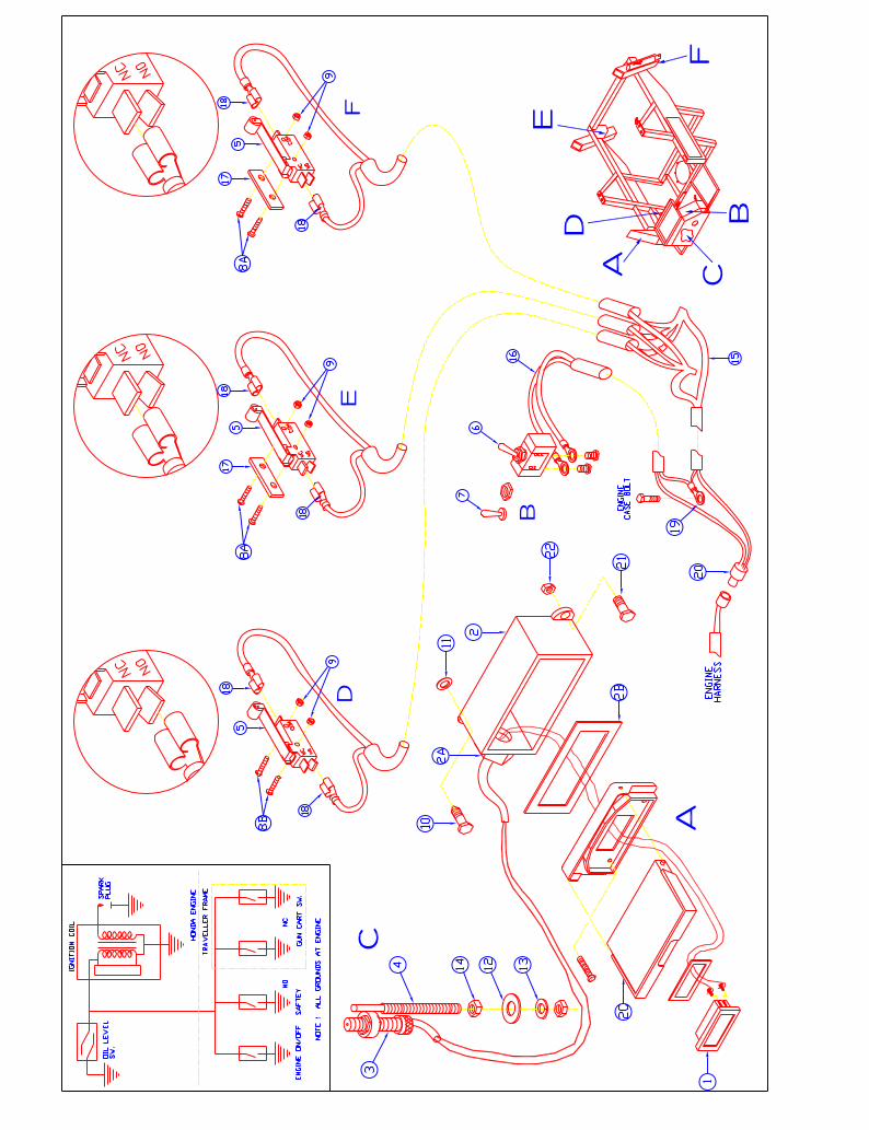
Elec
tric
al S
yste
m
Item
Des
crip
tion
P/N
Qty
.Ite
mD
escr
iptio
nP/
NQ
ty.
1S
peed
omet
er K
it40
-190
-RL
12
PV
C B
ox40
-262
12A
Stra
in R
elie
f Kit,
3/4
"40
-263
12B
Gas
ket
40-2
641
2CB
ox c
over
w/li
d40
-271
13
Mag
netic
Pic
kup
Ass
'y, 5
/8" D
ia.
40-2
39-R
L1
4P
icku
p M
ount
07
-645
15
Shu
t Off
Sw
itch
40-0
203
6O
n/O
ff To
ggle
Sw
itch
40-2
601
7To
ggle
Sw
itch
Boo
t40
-261
18A
Mac
hine
Scr
ew, #
6-32
x 1
3/4
" Lg.
90-S
CR
-RM
0632
X17
54
8BM
achi
ne S
crew
, #6-
32 x
1" L
g.90
-SC
R-R
M06
32X
100
29
Lock
nut,
#6-3
290
-NU
T-LO
C00
6-32
610
Tek
Scr
ew, 1
/4" x
1" L
g.90
-SC
R-T
EK
025X
100
211
Nyl
on F
latw
ashe
r, 1/
4"90
-WS
R-F
LT02
5NY
LON
212
SA
E F
latw
ashe
r, 1/
2"90
-WS
R-S
AE
050
113
Lock
was
her,
1/2"
90-W
SR
-LO
C05
01
14H
exnu
t, 1/
2" -
1390
-NU
T-H
EX
050-
132
15W
ire H
arne
ss, 2
625/
3000
S40
-276
1-
Wire
Har
ness
, 225
040
-306
116
On/
Off
Sw
itch
Har
ness
40-2
771
17S
witc
h S
pace
r Blo
ck04
-628
218
Fem
ale
Spa
de C
onne
ctor
40-0
686
19Te
rmin
al E
ye, #
10 B
lue
40-0
691
20M
ale
Bul
let C
onne
ctor
, Blu
e40
-070
121
Bol
t, 1/
4" x
3/4
"Lg.
90-B
LT-2
520X
075
122
Lock
nut,
1/4"
90-N
UT-
LOC
025-
201 29-0
6-09
39
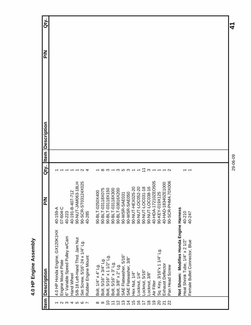
4.0
HP
Engi
ne A
ssem
bly
Item
Des
crip
tion
P/N
Qty
.Ite
mD
escr
iptio
nP/
NQ
ty.
14.
0 H
P H
onda
Eng
ine,
GX
120K
1HX
40-1
59-A
12
Eng
ine
Mou
nt P
late
07-6
04-C
13
6" V
aria
ble
Spe
ed P
ulle
y w
/Cam
40-2
231
4H
and
Whe
el40
-191
-B-4
07-7
121
55/
8-18
Lef
t-Han
d Th
rd. J
am N
ut90
-NU
T-JA
M06
3-18
LH1
6S
et S
crew
, 5/1
6"-2
4 x
1/4"
Lg.
90-S
CR
-ST0
3124
X02
52
7R
ubbe
r Eng
ine
Mou
nt40
-285
4
8B
olt,
1/4"
x 4
" Lg.
90-B
LT-0
250X
400
19
Bol
t, 5/
16" x
3/4
" Lg.
90-B
LT-0
3118
X07
58
10B
olt,
5/16
" x 1
1/2
" Lg.
90-B
LT-0
3118
X15
03
11B
olt,
5/16
" x 3
" Lg.
90-B
LT-0
3118
X30
01
12B
olt,
3/8"
x 2
" Lg.
90-B
LT-0
3816
X20
03
13S
AE
Fla
twas
her,
5/16
"90
-WS
R-S
AE
031
514
SA
E F
latw
ashe
r, 3/
8"90
-WS
R-S
AE
050
315
Hex
Nut
, 1/4
"90
-NU
T-H
EX
025-
201
16Lo
cknu
t, 1/
4"90
-NU
T-LO
C05
2-20
117
Lock
nut,
5/16
"90
-NU
T-LO
C03
1-18
1118
Lock
nut,
3/8"
90-N
UT-
LOC
038-
163
19A
ir Fi
lter
40-H
DA
-172
10ZE
O50
51
20S
q. K
ey, 3
/16"
x 1
1/4"
Lg.
90-K
EY
-019
X12
51
21E
xhau
st D
efle
ctor
40-H
AD
-183
40ZE
1000
122
Pan
Hea
d S
crew
90-S
CR
-PH
M4.
70X
006
2
Not
Sho
wn:
Mod
ifies
Hon
da E
ngin
e H
arne
ssH
eat S
hrin
k Tu
be, 1
/4" x
2 1
/2"
40-2
101
Fem
ale
Bul
let C
onne
ctor
, Blu
e40
-247
1 29-0
6-09
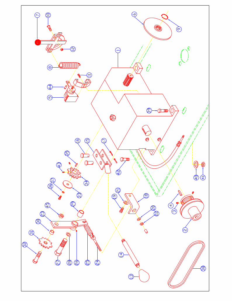
41
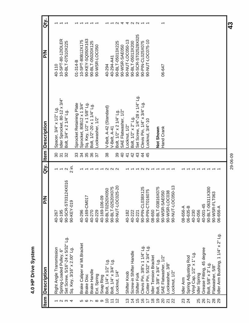
4.0
HP
Driv
e Sy
stem
Item
Des
crip
tion
P/N
Qty
.Ite
mD
escr
iptio
nP/
NQ
ty.
1R
ight
Ang
le T
rans
mis
sion
40-2
671
30S
pace
r, 3/
4" x
1/2
" Lg.
40-1
101
2S
prin
g-Lo
aded
Pul
ley,
6"
40-1
951
31Id
ler S
proc
ket,
80-1
2 x
3/4"
10-S
PT-
80-1
2ID
LER
13
Set
Scr
ew, 5
/16"
-24
x 5/
32" L
g.90
-SC
R-S
T031
24X
016
232
Bol
t, 3/
4" x
2 1
/4" L
g.90
-BLT
-075
10X
225
14
Sq.
Key
, 3/1
6" x
2.0
0" L
g.90
-KE
Y-0
192
in.
33S
proc
ket R
etai
ning
Pla
te01
-314
-B1
5B
rake
Cal
iper
w/ M
t.Bra
cket
40-2
961
34S
proc
ket,
80B
12 x
1 3
/4"
10-S
PT-
80B
12X
175
16
Bra
ke D
isc
40-1
69-C
M01
71
35S
q. K
ey, 1
/2" x
1 5
/8" L
g.90
-KE
Y-S
Q05
0X16
31
7B
rake
Han
dle
40-2
701
36B
olt,
1/2"
-20
x 1
1/4"
Lg.
90-B
LT-0
5020
X12
51
8E
xt. S
prin
g40
-229
137
Lock
was
her,
1/2"
90-W
SR
-LO
C05
01
9S
nap
Rin
g40
-169
-106
-09
110
Bol
t, 1/
4" x
1/2
" Lg.
90-B
LT02
520X
050
238
V-B
elt,
A-4
2 (S
tand
ard)
40-2
941
11B
olt,
1/4"
x 3
/4" L
g.90
-BLT
-025
20X
075
2V
-Bel
t, A
-41
40-2
94-A
411
12Lo
cknu
t, 1/
4"90
-NU
T-LO
C02
5-20
239
Bol
t, 1/
2" x
2 1
/4" L
g.90
-BLT
-050
13X
225
240
SA
E F
latw
ashe
r, 1/
2"90
-WS
R-S
AE
050
413
Shi
fter K
nob
40-1
821
41Lo
cknu
t, 1/
2"90
-NU
T-LO
C05
0-13
414
Scr
ew-in
Shi
fter H
andl
e40
-222
142
Bol
t, 1/
2" x
2" L
g.90
-BLT
-050
13X
200
215
Shi
fter F
ork
40-2
211
43S
et S
crew
, 1/4
"-28
x 1
/4" L
g.90
-SC
R-S
T025
28X
025
216
Cle
vis
Pin
, 3/8
"x 1
1/4
" Lg.
90-P
IN-C
L038
X12
52
44C
levi
s P
in, 1
/4" x
3/4
" Lg.
90-P
IN-C
L025
X07
51
17C
otte
r Pin
, 5/3
2" x
3/4
" Lg.
90-P
IN-C
T016
075
245
Lock
nut,
3/4"
-10
90-N
UT-
LOC
075-
101
18Id
ler T
ensi
on B
rack
et08
-650
119
Bol
t, 3/
8" x
3/4
" Lg.
90-B
LT-0
3816
X07
51
Not
Sho
wn
20S
AE
Fla
twas
her,
1/2"
90-W
SR
-SA
E05
01
Han
d C
rank
06-6
471
21Lo
ckw
ashe
r, 3/
8"90
-WS
R-L
OC
038
122
Lock
nut,
1/2"
90-N
UT-
LOC
050-
131
23Id
ler A
rm08
-656
-A1
24S
prin
g A
djus
ting
Rod
06-6
35-B
1V
inyl
Cap
, 1/2
" x 1
" Lg.
40-2
301
25Id
ler S
prin
g40
-056
126
Gre
ase
Fitti
ng, 4
5 de
gree
40-0
01-4
51
27B
olt,
5/8"
x 3
" Lg.
90-B
LT-0
6311
X30
01
28Fl
atw
ashe
r, 5/
8"90
-WS
R-F
LT06
31
29Id
ler A
rm B
ushi
ng, 1
1/4
" x 2
" Lg.
06-6
56-A
1 29-0
6-09
43
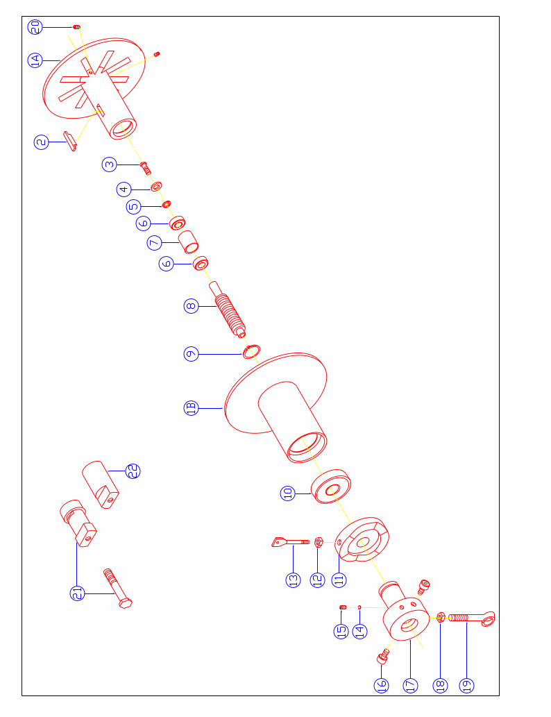
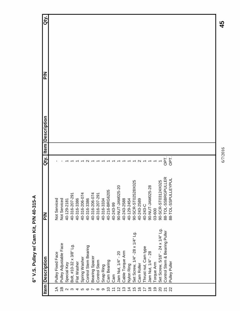
6" V
.S.
Pu
lle
y w
/ C
am
Kit
, P
/N 4
0-3
15
-A
Ite
mD
es
cri
pti
on
P/N
Qty
.It
em
Des
cri
pti
on
P/N
Qty
.
1A
Pulle
y F
ixed F
ace
Not S
erv
iced
-
1B
Pulle
y A
dju
sta
ble
Face
Not S
erv
iced
-
2S
pecia
l K
ey
40-1
29-2
181
1
3B
olt, #10-3
2 x
3/8
" Lg.
40-3
16-2
07-2
91
1
4F
lat W
asher
40-3
16-3
386
1
5S
pring W
asher
40-3
16-2
06-0
74
1
6C
ontr
ol S
tem
Bearing
40-3
16-3
386
2
7B
earing S
pacer
40-3
16-2
06-0
74
1
8C
ontr
ol S
tem
40-3
16-2
07-2
91
1
9S
nap R
ing
40-3
16-3
334
1
10
Cam
Bearing
40-2
16-B
RG
6205
1
11
Cam
40-2
43-9
91
12
Jam
Nut, 1
/4"
- 20
90-N
UT
-JA
M025-2
01
13
Cable
Torq
ue A
rm40-2
43-2
588
1
14
Nylo
n R
ing
40-1
29-2
454
1
15
Set S
cre
w, 1/4
" -2
8 x
1/4
" Lg.
90-S
CR
-ST
02528X
025
1
16
Cam
Rolle
r40-2
43-2
589
2
17
Thru
st nut, C
am
typ
e40-2
43-C
1
18
Jam
Nut, 1
/4"
- 28
90-N
UT
-JA
M025-2
81
19
Torq
ue A
rm03-6
00
1
20
Set S
cre
w, 5/1
6"
- 24 x
1/4
" Lg.
90-S
CR
-ST
03124X
025
1
21
Contr
ol S
tem
& B
earing P
ulle
r88-T
OL-S
SB
RG
PU
LLE
RO
PT
.
22
Pulle
y P
ulle
r88-T
OL-S
SP
ULLE
YP
UL
OP
T.
6/7
/2016
45
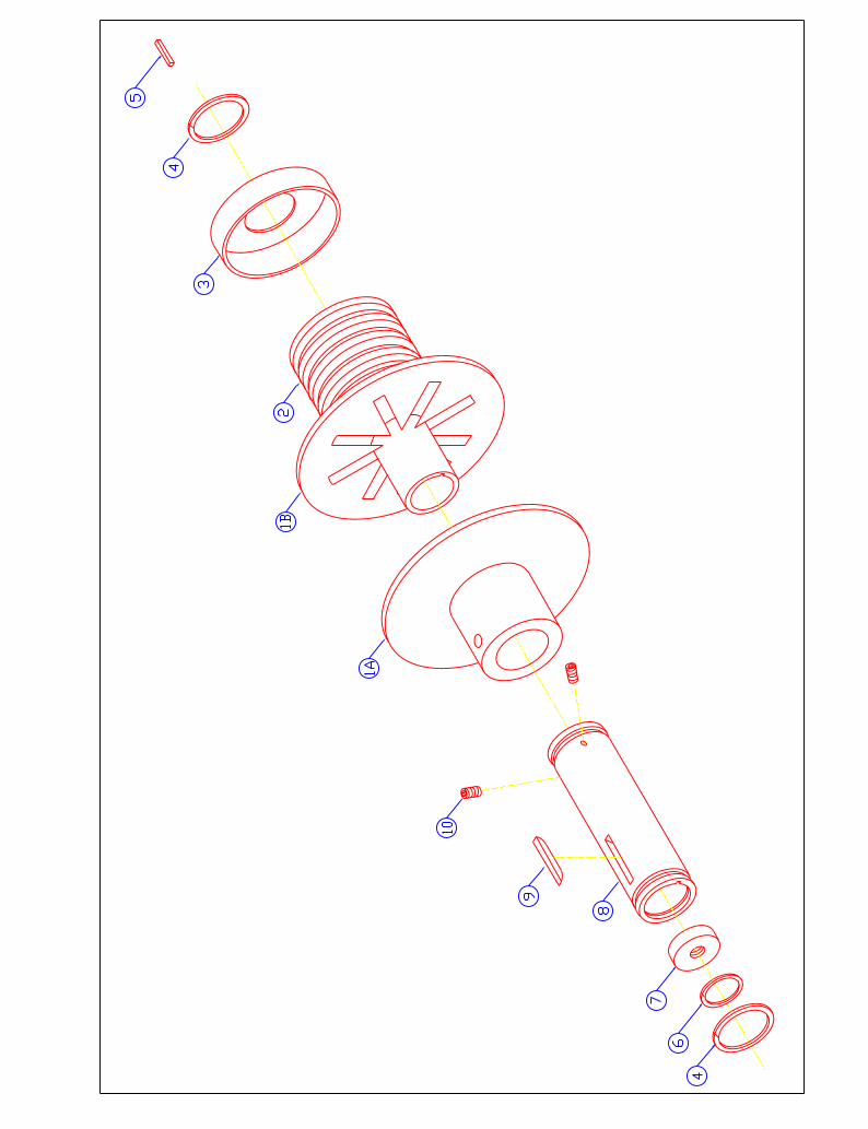
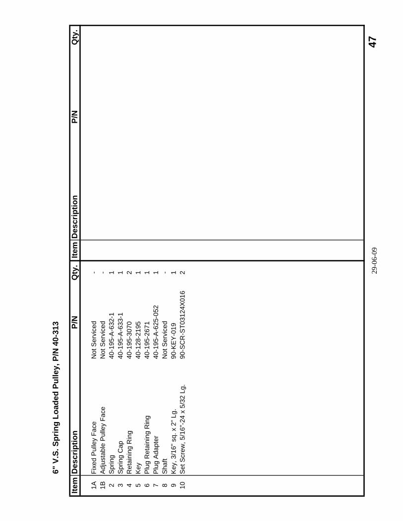
6" V
.S. S
prin
g Lo
aded
Pul
ley,
P/N
40-
313
Item
Des
crip
tion
P/N
Qty
.Ite
mD
escr
iptio
nP/
NQ
ty.
1AFi
xed
Pul
ley
Face
Not
Ser
vice
d-
1BA
djus
tabl
e P
ulle
y Fa
ceN
ot S
ervi
ced
-2
Spr
ing
40-1
95-A
-632
-11
3S
prin
g C
ap40
-195
-A-6
33-1
14
Ret
aini
ng R
ing
40-1
95-3
070
25
Key
40-1
28-2
195
16
Plu
g R
etai
ning
Rin
g40
-195
-267
11
7P
lug
Ada
pter
40-1
95-A
-625
-052
18
Sha
ftN
ot S
ervi
ced
-9
Key
, 3/1
6" s
q. x
2" L
g.90
-KE
Y-0
191
10S
et S
crew
, 5/1
6"-2
4 x
5/32
Lg.
90-S
CR
-ST0
3124
X01
62 29
-06-
09 4
7
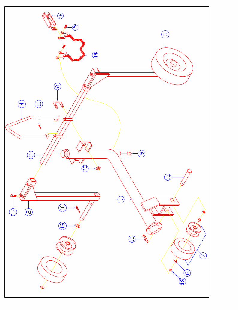
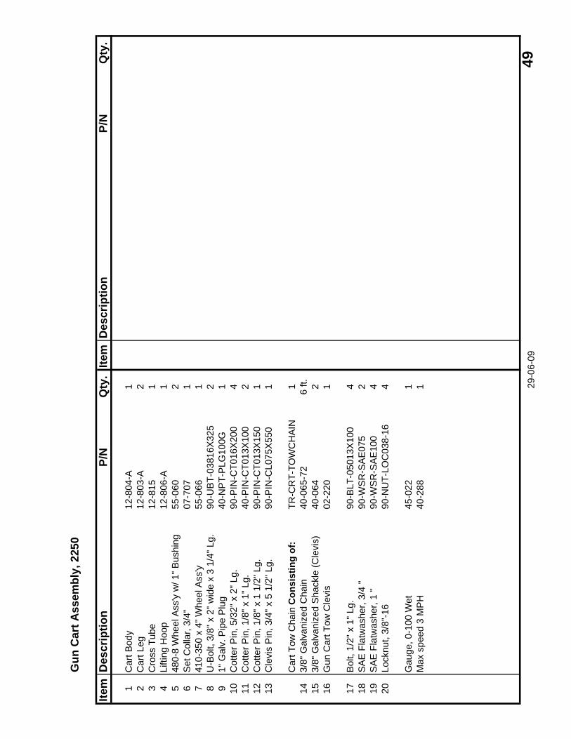
Gun
Car
t Ass
embl
y, 2
250
Item
Des
crip
tion
P/N
Qty
.Ite
mD
escr
iptio
nP/
NQ
ty.
1C
art B
ody
12-8
04-A
12
Car
t Leg
12-8
03-A
23
Cro
ss T
ube
12-8
151
4Li
fting
Hoo
p12
-806
-A1
548
0-8
Whe
el A
ss'y
w/ 1
" Bus
hing
55-0
602
6S
et C
olla
r, 3/
4"07
-707
17
410-
350
x 4"
Whe
el A
ss'y
55-0
661
8U
-Bol
t, 3/
8" x
2" w
ide
x 3
1/4"
Lg.
90-U
BT-
0381
6X32
52
91"
Gal
v. P
ipe
Plu
g40
-NP
T-P
LG10
0G1
10C
otte
r Pin
, 5/3
2" x
2" L
g.90
-PIN
-CT0
16X
200
411
Cot
ter P
in, 1
/8" x
1" L
g.
40-P
IN-C
T013
X10
02
12C
otte
r Pin
, 1/8
" x 1
1/2
" Lg.
90-P
IN-C
T013
X15
01
13C
levi
s P
in, 3
/4" x
5 1
/2" L
g.90
-PIN
-CL0
75X
550
1
Car
t Tow
Cha
in C
onsi
stin
g of
:TR
-CR
T-TO
WC
HA
IN1
143/
8" G
alva
nize
d C
hain
40-0
65-7
26
ft.15
3/8"
Gal
vani
zed
Sha
ckle
(Cle
vis)
40-0
642
16G
un C
art T
ow C
levi
s02
-220
1
17B
olt,
1/2"
x 1
" Lg.
90-B
LT-0
5013
X10
04
18S
AE
Fla
twas
her,
3/4
"90
-WS
R-S
AE
075
219
SA
E F
latw
ashe
r, 1
"90
-WS
R-S
AE
100
420
Lock
nut,
3/8"
-16
90-N
UT-
LOC
038-
164
Gau
ge, 0
-100
Wet
45-0
221
Max
spe
ed 3
MP
H40
-288
1 29-0
6-09
49
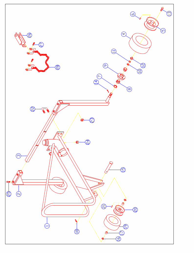
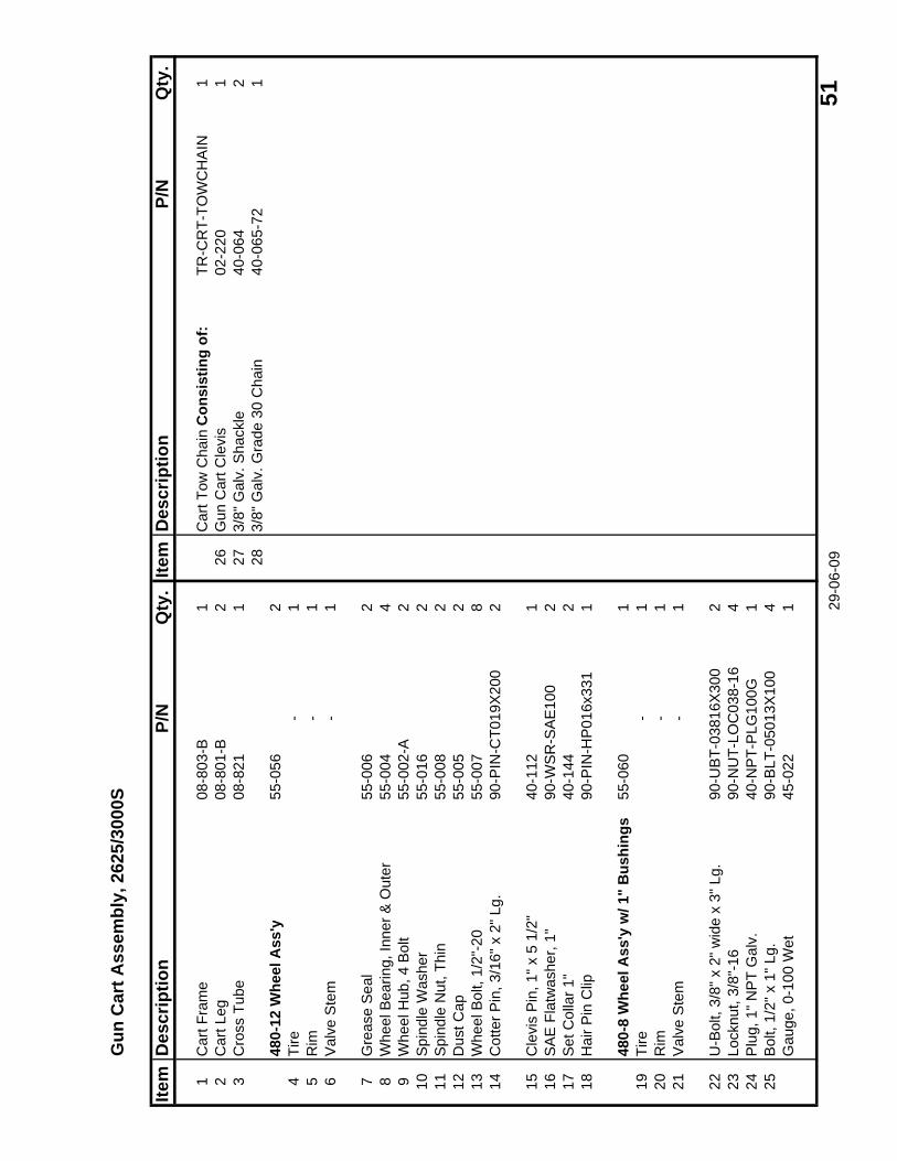
Gun
Car
t Ass
embl
y, 2
625/
3000
S
Item
Des
crip
tion
P/N
Qty
.Ite
mD
escr
iptio
nP/
NQ
ty.
1C
art F
ram
e08
-803
-B1
Car
t Tow
Cha
in C
onsi
stin
g of
:TR
-CR
T-TO
WC
HA
IN1
2C
art L
eg08
-801
-B2
26G
un C
art C
levi
s02
-220
13
Cro
ss T
ube
08-8
211
273/
8" G
alv.
Sha
ckle
40-0
642
283/
8" G
alv.
Gra
de 3
0 C
hain
40-0
65-7
21
480-
12 W
heel
Ass
'y55
-056
24
Tire
-1
5R
im-
16
Val
ve S
tem
-1
7G
reas
e S
eal
55-0
062
8W
heel
Bea
ring,
Inne
r & O
uter
55-0
044
9W
heel
Hub
, 4 B
olt
55-0
02-A
210
Spi
ndle
Was
her
55-0
162
11S
pind
le N
ut, T
hin
55-0
082
12D
ust C
ap55
-005
213
Whe
el B
olt,
1/2"
-20
55-0
078
14C
otte
r Pin
, 3/1
6" x
2" L
g.90
-PIN
-CT0
19X
200
2
15C
levi
s P
in, 1
" x 5
1/2
"40
-112
116
SA
E F
latw
ashe
r, 1"
90-W
SR
-SA
E10
02
17S
et C
olla
r 1"
40-1
442
18H
air P
in C
lip90
-PIN
-HP
016x
331
1
480-
8 W
heel
Ass
'y w
/ 1"
Bus
hing
s55
-060
119
Tire
-1
20R
im-
121
Val
ve S
tem
-1
22U
-Bol
t, 3/
8" x
2" w
ide
x 3"
Lg.
90-U
BT-
0381
6X30
02
23Lo
cknu
t, 3/
8"-1
690
-NU
T-LO
C03
8-16
424
Plu
g, 1
" NP
T G
alv.
40-N
PT-
PLG
100G
125
Bol
t, 1/
2" x
1" L
g.90
-BLT
-050
13X
100
4G
auge
, 0-1
00 W
et45
-022
1 29-0
6-09
51
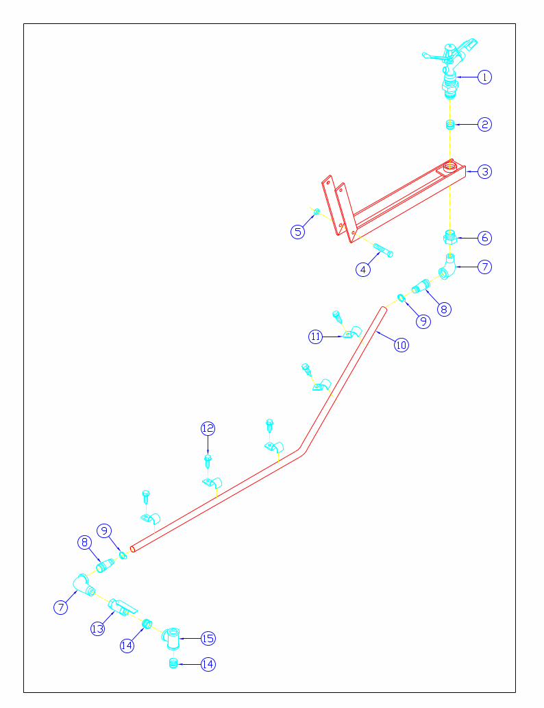
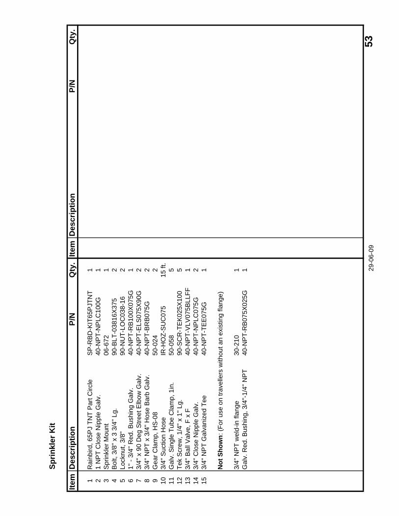
Sprin
kler
Kit
Item
Des
crip
tion
P/N
Qty
.Ite
mD
escr
iptio
nP/
NQ
ty.
1R
ainb
ird, 6
5PJ
TNT
Par
t Circ
leS
P-R
BD
-KIT
65P
JTN
T1
21
NP
T C
lose
Nip
ple
Gal
v.40
-NP
T-N
PLC
100G
13
Spr
inkl
er M
ount
06-6
721
4B
olt,
3/8"
x 3
3/4
" Lg.
90-B
LT-0
3816
X37
52
5Lo
cknu
t, 3/
8"90
-NU
T-LO
C03
8-16
26
1" -
3/4"
Red
. Bus
hing
Gal
v.40
-NP
T-R
B10
0X07
5G1
73/
4" x
90
Deg
Stre
et E
lbow
Gal
v.40
-NP
T-E
LS07
5X90
G2
83/
4" N
PT
x 3/
4" H
ose
Bar
b G
alv.
40-N
PT-
BR
B07
5G2
9G
ear C
lam
p, H
S-0
850
-024
210
3/4"
Suc
tion
Hos
eIR
-HO
Z-S
UC
075
15 ft
.11
Gal
v. S
ingl
e Tu
be C
lam
p, 1
in.
50-0
585
12Te
k S
crew
, 1/4
" x 1
" Lg.
90
-SC
R-T
EK
025X
100
513
3/4"
Bal
l Val
ve, F
x F
40-N
PT-
VLV
075B
LLFF
114
3/4"
Clo
se N
ippl
e G
alv.
40-N
PT-
NP
LC07
5G2
153/
4" N
PT
Gal
vani
zed
Tee
40-N
PT-
TEE
075G
1
Not
Sho
wn:
(For
use
on
trave
llers
with
out a
n ex
istin
g fla
nge)
3/4"
NP
T w
eld-
in fl
ange
30-2
101
Gal
v. R
ed. B
ushi
ng, 3
/4"-
1/4"
NP
T40
-NP
T-R
B07
5X02
5G1 29
-06-
09 5
3
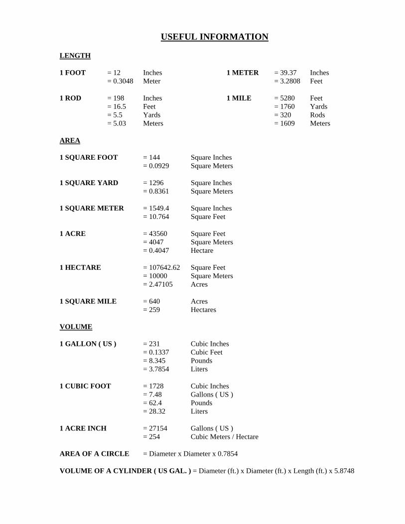
USEFUL INFORMATION
LENGTH 1 FOOT = 12 Inches 1 METER = 39.37 Inches
= 0.3048 Meter = 3.2808 Feet 1 ROD = 198 Inches 1 MILE = 5280 Feet = 16.5 Feet = 1760 Yards = 5.5 Yards = 320 Rods = 5.03 Meters = 1609 Meters AREA 1 SQUARE FOOT = 144 Square Inches = 0.0929 Square Meters 1 SQUARE YARD = 1296 Square Inches = 0.8361 Square Meters 1 SQUARE METER = 1549.4 Square Inches = 10.764 Square Feet 1 ACRE = 43560 Square Feet = 4047 Square Meters = 0.4047 Hectare 1 HECTARE = 107642.62 Square Feet = 10000 Square Meters = 2.47105 Acres 1 SQUARE MILE = 640 Acres = 259 Hectares VOLUME 1 GALLON ( US ) = 231 Cubic Inches = 0.1337 Cubic Feet = 8.345 Pounds = 3.7854 Liters 1 CUBIC FOOT = 1728 Cubic Inches = 7.48 Gallons ( US ) = 62.4 Pounds = 28.32 Liters 1 ACRE INCH = 27154 Gallons ( US ) = 254 Cubic Meters / Hectare AREA OF A CIRCLE = Diameter x Diameter x 0.7854 VOLUME OF A CYLINDER ( US GAL. ) = Diameter (ft.) x Diameter (ft.) x Length (ft.) x 5.8748
Related Documents