Cabling Guidelines for INTRON-D / INTRON-D plus Systems Doc. no. 330-001-403 • Rev. 9 • EN • 15.10.2010

Welcome message from author
This document is posted to help you gain knowledge. Please leave a comment to let me know what you think about it! Share it to your friends and learn new things together.
Transcript

Cabling Guidelines for INTRON-D / INTRON-D plus Systems
Doc. no. 330-001-403 • Rev. 9 • EN • 15.10.2010
Table of Contents 1 Introduction............................................................................................................ 3
2 Abbreviations......................................................................................................... 3
3 Applicable Documents / Standards ..................................................................... 3
4 Cabling Scheme..................................................................................................... 4 4.1 Example System ............................................................................................. 4
5 Cable Types suitable for System Components................................................... 5 5.1 Cables for Intercom Stations........................................................................... 5
5.1.1 General Guidelines......................................................................................... 5 5.1.2 Laying of Cables in Outdoor Areas ................................................................ 6 5.1.3 Cable Laying Inside a Building ....................................................................... 7 5.1.4 Cable Laying in Explosive Areas.................................................................... 7
5.2 Loudspeaker Cables ....................................................................................... 8 5.3 Cables for Flashing Beacons .......................................................................... 8 5.4 Cables for 48 V / 60 V Battery Supplies.......................................................... 8 5.5 Fiber-optic Cables........................................................................................... 9 5.6 Antenna and Antenna Cables ......................................................................... 9
6 Grounding concept / Potential Equalization ..................................................... 10 6.1 Central Exchange Unit / System Voltage...................................................... 10 6.2 Periphery / Grounding in Ex Areas ............................................................... 11 6.3 Grounding of Armoured Cables .................................................................... 13
6.3.1 One-sided Insulated Armouring.................................................................... 14 6.3.2 Armouring Grounded at Both Sides ............................................................. 14 6.3.3 Grounding by Off-Shore-Plates .................................................................... 16
7 Wire Requirement Table for Digital Stations and Speakers ............................ 17 7.1 Speech Applications ..................................................................................... 17 7.2 Speech and Signal Applications ................................................................... 17 7.3 Radio Applications ........................................................................................ 18 7.4 Speaker Cabling ........................................................................................... 18
8 Gland Sizes and Cable Data ............................................................................... 20 8.1 Gland Sizes................................................................................................... 20 8.2 Outside Diameter of Cables.......................................................................... 21 8.3 Wire Diameter / Wire Cross Section ............................................................. 22 8.4 Technical Data on Telecom Cables .............................................................. 22
9 Conversion into Anglo-American Dimensions (AWG) ..................................... 23
Document History and Imprint .................................................................................. 24
Cabling Guidelines for INTRON-D / INTRON-D plus 2 / 24 Doc. no. 330-001-403 • Rev. 9 • EN • 15.10.2010
1 Introduction This document outlines the general rules for the cabling of communication and public address systems of types INTRON-D and in particular INTRON-D plus from INDUSTRONIC.
2 Abbreviations
EL Public addressing e.g. one-way communication within speaker circuits (= PA technology) or to intercom stations without talk-back facility
TC Telecom- e.g. TC cable = telecom cable
INTERCOM Generic term for communication techniques, e.g two-way communication, party line, telephony, radio etc.
INTRON-D / INTRON-D plus
Fully digital INDUSTRONIC system
ISDN Integrated Services Digital Network = hardware platform for intercom devices
LINE Pair of wires for the transmission of digitalized voice /control signals and phantom powering of an intercom station
LK Speaker circuit OFF-SHORE Special technology for installation on drilling rigs with common
grounding plate for cable gland PA Potential equalization PE Protection Earth = Schutzerde WL Two-way communication (half duplex), i.e. pressing the talk
key for talking, releasing the key for listening
3 Applicable Documents / Standards System documentation for the reference project (if any) Wiring calculation guidelines for analog systems: 330-001-015 VDE 0100: Guidelines for the erection of high voltage systems up to 1000V VDE 0165; EN 60079-14: Erecting electric systems in hazardous areas IEC / EN 60079- ... Ex Protection types VDE 0800 Intercom technology VDE 0815 Cables for installation in telecom and data processing systems VDE 0816 Outdoor cables for telecom systems
Cabling Guidelines for INTRON-D / INTRON-D plus 3 / 24 Doc. no. 330-001-403 • Rev. 9 • EN • 15.10.2010
4 Cabling Scheme In order to guarantee highest safety and availability of the INDUSTRONIC intercom systems, cables to intercom stations and centrally supplied loudspeaker groups etc. are generally laid by starting at the central exchange unit. Only the cross connections between parallel loudspeakers and the connections of a station's subcomponents are laid on site. Junction boxes for the cabling will be applied on customer's request.
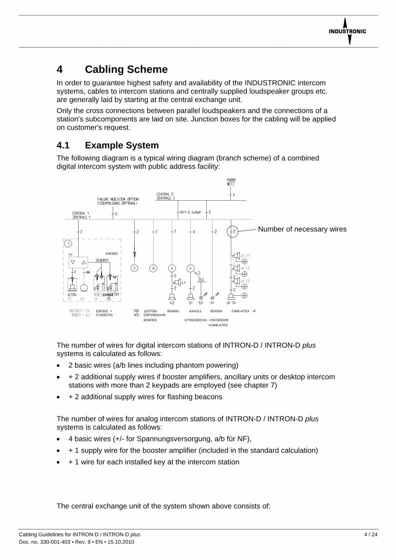
4.1 Example System The following diagram is a typical wiring diagram (branch scheme) of a combined digital intercom system with public address facility:
Number of necessary wires
1DES03
1MH14
1DES02 + 2*16DET01
+CWB-ATEX 6DWS01 +2*HS15EEmN +HS15EEmN
12DT00x 6DA00x AXA311 6DX00x CWB-ATEX 4* DSP25EExmN
The number of wires for digital intercom stations of INTRON-D / INTRON-D plus systems is calculated as follows: • 2 basic wires (a/b lines including phantom powering) • + 2 additional supply wires if booster amplifiers, ancillary units or desktop intercom
stations with more than 2 keypads are employed (see chapter 7) • + 2 additional supply wires for flashing beacons The number of wires for analog intercom stations of INTRON-D / INTRON-D plus systems is calculated as follows: • 4 basic wires (+/- for Spannungsversorgung, a/b für NF), • + 1 supply wire for the booster amplifier (included in the standard calculation) • + 1 wire for each installed key at the intercom station The central exchange unit of the system shown above consists of:
Cabling Guidelines for INTRON-D / INTRON-D plus 4 / 24 Doc. no. 330-001-403 • Rev. 9 • EN • 15.10.2010

• Central exchange cabinet 1 with exchange facility • Central exchange cabinet 2 with power supply and battery backup The following peripheral units are used: • Station 1: Digital flush-mounted intercom station with 32 keys • Station 2: Digital desktop intercom station with 12 keys, dial keypad, display and
wall socket • Station 3: Digital outdoor intercom station with 6 keys • Station 4: Analog explosion-proof intercom station with 2 keys, booster amplifier
and 2 explosion-proof loudspeakers • Station 5: Digital explosion-proof intercom station with 6 keys, booster amplifier, 1
explosion-proof loudspeaker and flashing beacon with junction box • H1: Explosion-proof flashing beacon • LK1: 4x Explosion-proof loudspeakers (central power supply, local grounding)
5 Cable Types suitable for System Components Depending on the various components of the communication system, different cable types are applied. Please, note that cables for the periphery of the communication system must not be laid next to high-voltage cables, power cables or cables with large RF or harmonics shares (e.g. for rotary current thyristor drives). There should be a minimum distance of 30 cm to such cables.
5.1 Cables for Intercom Stations
5.1.1 General Guidelines Cables which connect intercom stations with the central exchange unit must principally have twisted pair wires or star quad wires. Thus, possible interferences and alternating fields cannot impair the quality of the communication. Normally, further protection of the cables is not necessary. For guidelines on armoured cables, please refer to item 6.3. Cables are laid according to local rules, e.g. on flat beds or in conduits. Depending on the lengths of the cables, some wires for intercom stations may have to be connected in parallel. Regarding digital intercom stations, further instructions on this subject can be taken from chapter 7 and regarding analog stations from document no. 330-001-015.
Cabling Guidelines for INTRON-D / INTRON-D plus 5 / 24 Doc. no. 330-001-403 • Rev. 9 • EN • 15.10.2010

5.1.2 Laying of Cables in Outdoor Areas For outdoor intercom stations, telecom cables are applied usually. INDUSTRONIC recommends the A2Y(L)2Y .... x2x0,8 ST III Bd cable types. These are designed for industrial ambient conditions and are mechanically stable. Cable Structure A2Y(L)2Y ... (according to DIN VDE 0816):
Outer sheath: PE (reinforced)
Static screen: plastic covered aluminium band k t t ffb hi ht tStranding: star quad twisting
Plastic foil
Conductor: bare copper wire
Please, note that, with star quad twisting, pairs are formed by opposite wires (not by neighbouring ones).
Insulation of the wires: polyethelene
Marking for unit stranded cables A2Y(L)2Y ... according to VDE 0816: The wires of a quad are marked by rings. Pairs (branches) are formed by opposite wires.
Branch 1 Star quad a - wire (without ring)
b - wire
Branch 2 a - wire
b - wire Five star quads with differently colored wires form one bundle. Quad 1: red Quad 2: green Quad 3: grey Quad 4: yellow Quad 5: white Bundles where the counting starts anew are marked by red helixes. For further technical details, please, refer to chapter 8.
Cabling Guidelines for INTRON-D / INTRON-D plus 6 / 24 Doc. no. 330-001-403 • Rev. 9 • EN • 15.10.2010
Cabling Guidelines for INTRON-D / INTRON-D plus 7 / 24 Doc. no. 330-001-403 • Rev. 9 • EN • 15.10.2010
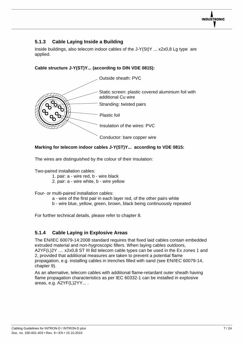
5.1.3 Cable Laying Inside a Building Inside buildings, also telecom indoor cables of the J-Y(St)Y ... x2x0,8 Lg type are applied. Cable structure J-Y(ST)Y... (according to DIN VDE 0815):
Marking for telecom indoor cables J-Y(ST)Y... according to VDE 0815: The wires are distinguished by the colour of their insulation: Two-paired installation cables:
1. pair: a - wire red, b - wire black 2. pair: a - wire white, b - wire yellow
Four- or multi-paired installation cables: a - wire of the first pair in each layer red, of the other pairs white b - wire blue, yellow, green, brown, black being continuously repeated
For further technical details, please refer to chapter 8.
5.1.4 Cable Laying in Explosive Areas The EN/IEC 60079-14:2008 standard requires that fixed laid cables contain embedded extruded material and non-hygroscopic fillers. When laying cables outdoors, A2YF(L)2Y .... x2x0,8 ST III Bd telecom cable types can be used in the Ex zones 1 and 2, provided that additional measures are taken to prevent a potential flame propagation, e.g. installing cables in trenches filled with sand (see EN/IEC 60079-14, chapter 9). As an alternative, telecom cables with additional flame-retardant outer sheath having flame propagation characteristics as per IEC 60332-1 can be installed in explosive areas, e.g. A2YF(L)2YY... .
Outside sheath: PVC
Static screen: plastic covered aluminium foil with additional Cu wireStranding: twisted pairs
Plastic foil
Insulation of the wires: PVC
Conductor: bare copper wire
According to EN/IEC 60079-14:2008 free wires ending in the Ex “e” compartments of devices installed in explosive areas must be properly insulated using terminals suitable for this type of ignition protection. Using only an insulating tape for insulation is not permitted. Cables leading to DX or DXG type intercom stations must have appropriate dimensions to connect all wires to the existing terminals. Two cores of same wire type and diameter can be connected to one terminal up to a cross section of 1 mm2.
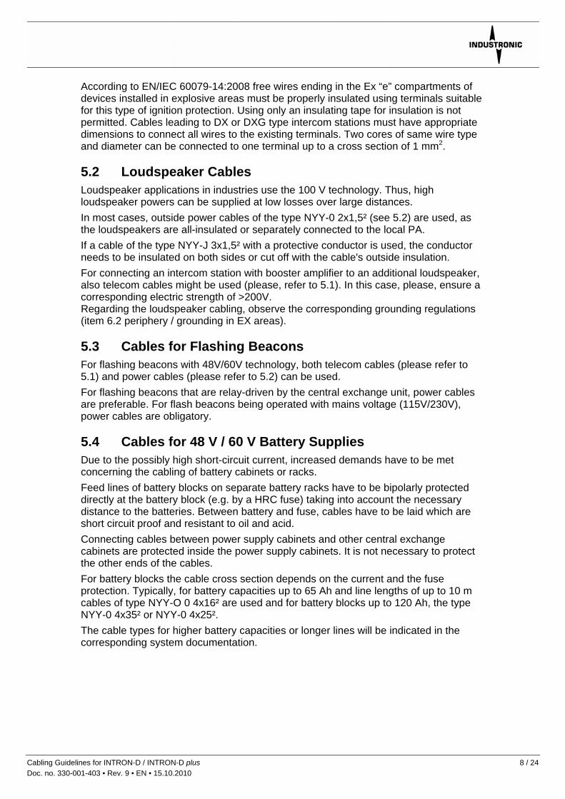
5.2 Loudspeaker Cables Loudspeaker applications in industries use the 100 V technology. Thus, high loudspeaker powers can be supplied at low losses over large distances. In most cases, outside power cables of the type NYY-0 2x1,5² (see 5.2) are used, as the loudspeakers are all-insulated or separately connected to the local PA. If a cable of the type NYY-J 3x1,5² with a protective conductor is used, the conductor needs to be insulated on both sides or cut off with the cable's outside insulation. For connecting an intercom station with booster amplifier to an additional loudspeaker, also telecom cables might be used (please, refer to 5.1). In this case, please, ensure a corresponding electric strength of >200V. Regarding the loudspeaker cabling, observe the corresponding grounding regulations (item 6.2 periphery / grounding in EX areas).
5.3 Cables for Flashing Beacons For flashing beacons with 48V/60V technology, both telecom cables (please refer to 5.1) and power cables (please refer to 5.2) can be used. For flashing beacons that are relay-driven by the central exchange unit, power cables are preferable. For flash beacons being operated with mains voltage (115V/230V), power cables are obligatory.
5.4 Cables for 48 V / 60 V Battery Supplies Due to the possibly high short-circuit current, increased demands have to be met concerning the cabling of battery cabinets or racks. Feed lines of battery blocks on separate battery racks have to be bipolarly protected directly at the battery block (e.g. by a HRC fuse) taking into account the necessary distance to the batteries. Between battery and fuse, cables have to be laid which are short circuit proof and resistant to oil and acid. Connecting cables between power supply cabinets and other central exchange cabinets are protected inside the power supply cabinets. It is not necessary to protect the other ends of the cables. For battery blocks the cable cross section depends on the current and the fuse protection. Typically, for battery capacities up to 65 Ah and line lengths of up to 10 m cables of type NYY-O 0 4x16² are used and for battery blocks up to 120 Ah, the type NYY-0 4x35² or NYY-0 4x25². The cable types for higher battery capacities or longer lines will be indicated in the corresponding system documentation.
Cabling Guidelines for INTRON-D / INTRON-D plus 8 / 24 Doc. no. 330-001-403 • Rev. 9 • EN • 15.10.2010

5.5 Fiber-optic Cables For INTRON-D intercom systems INDUSTRONIC offers INTRON-D / INTRON-D plus components which serve to set up subcentrals (satellites) or couple several central exchange units. These components are connected by fibre-optic cables. Electro-magnetic interferences can be excluded on such cables. Existing fibres, e.g. at crane applications, can be made use of. The following items have to be observed: For each route you need two fibres which must be exclusively available for the INTRON-D / INTRON-D plus systems. • Use optic fibres of gradient type 50/125μm or 62.5/125μm, alternatively single-
mode fibers 9/125μm, suitable for the component • Use only one fiber type for one connection. • Max. cable length 3 km per fiber • Max. allowed attenuation <12dB @ 62.5/125μm / <7dB @ 50/125μm / <15dB @
9/125μm • Pay attention to the relevant handling guidelines of the cable manufacturer • Avoid bending and joints which are not absolutely needed • The subcentral requires its own power supply • Do not strain mechanically the fibre optic cables or connection plugs of the
INTRON-D / INTRON-D plus components
5.6 Antenna and Antenna Cables INDUSTRONIC provides radio components for its INTRON-D plus systems, thus allowing for the integration of crane stations, vehicles or handheld devices into the communication systems. When installing those radio components, please observe the following: • The positions of the antennae of the base stations and of the antennae of the
corresponding mobile stations should be selected to allow "visual contact". • The antenna cables must be properly laid. • Never bend the antenna cables below their bending radius, not even during the
installation process. The radius depends on the cable type used. • Depending on the type of antenna, the antenna might have to be installed on a
metal ground screen. Detailed installation instructions can be taken from the INDUSTRONIC document no. 330-013-031.
Cabling Guidelines for INTRON-D / INTRON-D plus 9 / 24 Doc. no. 330-001-403 • Rev. 9 • EN • 15.10.2010
6 Grounding concept / Potential Equalization
6.1 Central Exchange Unit / System Voltage Grounding serves as protection from overvoltage in direct current and low frequency areas. A central exchange cabinet with live components requires all electrically conductive parts to be properly grounded. Furthermore, grounding is essentially necessary in order to "shield" the complete system effectively. Consequently, all side panels, roofs and doors of INDUSTRONIC cabinets are already electrically connected as a standard. Therefore, on site you only have to shunt the complete cabinet to the corresponding ground potential. This saves time during installation and rules out possible sources of trouble. Connect the equipotential busbar in the installation room via a grounding line with the central grounding point in the cabinet.
The central grounding point in the cabinet is marked . The grounding line is required according to general regulations to have at least a conductor cross-section as indicated in the following table:
Conductor cross-section From to Distance mm² AWG
Equipotential busbar installation room
Grounding point central exchange cabinet
< 10 m > 10 m
10 16
6 4
Note: AWG means "American Wire Gage" and is generally used in North America for measuring conductors. Those values are indicated as information only. INDUSTRONIC central exchange cabinets generally have to be connected to the local system ground (protective ground PE). Every cabinet has a grounding knot. As a rule, the system voltage for INDUSTRONIC intercom systems is 60VDC or 48VDC. This system voltage is not grounded in order to avoid parasitic inductions and ground returns. In case overvoltage protection modules are used for connected station lines, the negative pole of the supply voltage must be grounded. Otherwise, there is the danger that the system voltage separates from the ground potential releasing the overvoltage arresters. In order to exclude interferences the system voltage is connected to ground via an inductance. INDUSTRONIC does not use function grounds as described in VDE 0800.
Cabling Guidelines for INTRON-D / INTRON-D plus 10 / 24 Doc. no. 330-001-403 • Rev. 9 • EN • 15.10.2010
6.2 Periphery / Grounding in Ex Areas According to VDE 0100 all (not all-insulated) stationary electrical devices with metal housings must be grounded. Regarding the peripheral units from INDUSTRONIC, this applies only to metal loudspeakers, flash lamps and junction boxes and possible project-specific special units. INDUSTRONIC intercom stations have a protective insulation and do not provide of a grounding connection. If a component that must be grounded, e.g. a metal loudspeaker, has to be connected to an intercom station, the loudspeaker will be locally grounded (potential equalization PA). Flashing beacons and metal loudspeakers that are supplied by the central exchange unit as well as noise absorbing hoods will be locally grounded, too. Attention: In EX areas all metal parts (also non-electrical ones) from a certain size upward are on site electrically connected to the potential equalization of the respective area. Even a small potential difference of only some V could already cause a spark which then could lead to an explosion (please, also refer to 6.3 “Grounding of Armoured Cables”). However: PA areas set by the customers must remain isolated from each other! Therefore, it must be taken care that the armourings or shieldings of cables between different PA areas are insulated at least at one end! Otherwise, equalizing currents of up to several kilo Ampère could arise there! Additionally, there could emerge interferences in the cable that would impair the quality of the communication. Thus, INDUSTRONIC recommends not to ground the armouring or shielding!
Cabling Guidelines for INTRON-D / INTRON-D plus 11 / 24 Doc. no. 330-001-403 • Rev. 9 • EN • 15.10.2010

System example: The following diagram shows a branch scheme of a system with various PA areas. The armourings or shieldings of the cables must in any case end insulated at the marked places! The PA areas are defined by the customer and have to be communicated to INDUSTRONIC® for the cable engineering. .
Junction box of PA area A with cables to other PA areas. The armourings/shieldings of the cables must end insulated here! Off-shore technology is not allowed here!
Central exchange outside the PA areas. Cabinet grounded to the system ground, outgoing cable not grounded.
Off-shore junction boxes of the PA areas B and C with cables locally grounded inside the respective PA area. All metal parts of one area are electrically connected. There must not flow any equalizing currents between the PA areas A, B, C!
Cabling Guidelines for INTRON-D / INTRON-D plus 12 / 24 Doc. no. 330-001-403 • Rev. 9 • EN • 15.10.2010

6.3 Grounding of Armoured Cables On request of the customer, armoured cables may be used in certain cases. Armouring represents a mechanical protection of the cable but can also be used for shielding. Potential equalization via the armouring cannot be recommended but should be measured or dimensioned in each particular case and belongs to the responsibility of the customer. If the armouring is used as electrical shielding, the shielding should be grounded at one side only to protect against ground returns and equalizing currents, i.e. the armouring should end insulated in a plastic gland. INDUSTRONIC does not recommend the armouring's grounding at both sides. This would be allowed only within a PA area and could cause interferences of the communication quality. Please, also note the instructions of item 6.2! If special metal armoured glands as per customer's request are used, the following parameters always have to be indicated when selecting the glands: • Outside cable diameter • Outside diameter of the armouring • Desired type of thread • Ambient conditions (range of temperatures, IP protection degree) • Industrial or Ex version (Ex-d, Ex-e) • Sealing:
- only outside sheath - only inside sheath - outside and inside sheath - outside sheath and lead cover
• Armouring type and wire strength The following types of armouring are available: • Steel tape armouring (DSTA) • Single wire armouring (SWA) • Wire braid armouring (wire braid) • Aluminium tape armouring (AWA + ASA) Please, note that bulky glands might perhaps allow only one entry at each side of the housing as the distance between the glands is predefined by the prepared thread inset plate.
Cabling Guidelines for INTRON-D / INTRON-D plus 13 / 24 Doc. no. 330-001-403 • Rev. 9 • EN • 15.10.2010
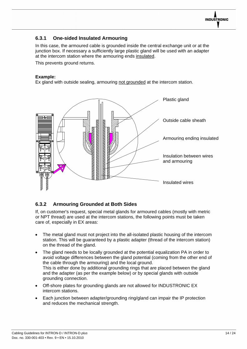
6.3.1 One-sided Insulated Armouring In this case, the armoured cable is grounded inside the central exchange unit or at the junction box. If necessary a sufficiently large plastic gland will be used with an adapter at the intercom station where the armouring ends insulated. This prevents ground returns. Example: Ex gland with outside sealing, armouring not grounded at the intercom station.
Plastic gland
Outside cable sheath
Armouring ending insulated
Insulation between wires and armouring
Insulated wires
6.3.2 Armouring Grounded at Both Sides If, on customer's request, special metal glands for armoured cables (mostly with metric or NPT thread) are used at the intercom stations, the following points must be taken care of, especially in EX areas: • The metal gland must not project into the all-isolated plastic housing of the intercom
station. This will be guaranteed by a plastic adapter (thread of the intercom station) on the thread of the gland.
• The gland needs to be locally grounded at the potential equalization PA in order to avoid voltage differences between the gland potential (coming from the other end of the cable through the armouring) and the local ground. This is either done by additional grounding rings that are placed between the gland and the adapter (as per the example below) or by special glands with outside grounding connection.
• Off-shore plates for grounding glands are not allowed for INDUSTRONIC EX intercom stations.
• Each junction between adapter/grounding ring/gland can impair the IP protection and reduces the mechanical strength.
Cabling Guidelines for INTRON-D / INTRON-D plus 14 / 24 Doc. no. 330-001-403 • Rev. 9 • EN • 15.10.2010

Example: EX gland with inside and outside sealing for steel wire armoured cables, locally grounded by a separate grounding ring and grounding wire.
Plastic adapter M25
Grounding connection of the armouring by separate grounding
Armouring gland
Armouring connected to the gland by a cone
Steel wire armoured cable
Cabling Guidelines for INTRON-D / INTRON-D plus 15 / 24 Doc. no. 330-001-403 • Rev. 9 • EN • 15.10.2010

Cabling Guidelines for INTRON-D / INTRON-D plus 16 / 24 Doc. no. 330-001-403 • Rev. 9 • EN • 15.10.2010
6.3.3 Grounding by Off-Shore-Plates If armoured cables are used in connection with junction boxes, the metal glands of the incoming and outgoing cables are electrically connected with each other by so-called off-shore plates at the junction boxes and are connected to the local ground (potential equalization). This is admissible only within each PA area. Please, also note our instructions as per item 6.2! Off-shore plates are brass plates in the junction box housing with cut threads where the glands are screwed in and thus grounded. Off-shore plates must not be inserted into INDUSTRONIC EX intercom stations! Example: Plastic junction box with off-shore technology, metal EX armouring glands, grounded by an inserted off-shore plate.
Grounding connection of the off-shore plate, e.g. to the grounding terminal and, by another gland, directly to the local ground (PA)
Off-Shore plate (brass)
Armouring gland, screwed through the housing into the off-shore plate
Steel wire armoured cable

7 Wire Requirement Table for Digital Stations and Speakers
Wires for additional power supply For the connection of a digital intercom station, two wires are normally required. However, we recommend to lay at least 4 wires to all intercom stations, even if they should not yet be necessary at the time of installation. Within a distance of 2 km to the central exchange unit, modular desktop intercom stations and flush-mounted intercom stations with up to 2 keypads can be operated via two wires. If the distance is greater or if there are more than 2 keypads, two further wires are necessary for the power supply. If the relevant station has a booster amplifier, the electronics can be fed via the amplifier’s supply lines. Safety note: To avoid breakdown times and subsequent costs because of broken wires, we suggest to provide additional spare wires, especially for long distances (e.g. > 1000 meters). Since the power consumption of an intercom station receiving continuous tone signals is higher than when receiving voice signals, the wire requirements are calculated separately for both cases.
7.1 Speech Applications Depending on the length of cables the number of wires is to be calculated as follows: Wire diameter = 0.8 mm:
System Voltage Cable length Wires for a/b line
Wires for additional amplifier
Total number of wires
60 V DC 0 to 1500 m 2 2 4 1500 to 4000 m 2 4 6 68 V DC 0 to 2000 m 2 2 4 2000 to 4000 m 2 4 6
7.2 Speech and Signal Applications Depending on the length of cables the number of wires is to be calculated as follows: Wire diameter = 0.8 mm:
System Voltage Cable length Wires for a/b line
Wires for additional amplifier
Total number of wires
60 V DC 0 to 500 m 2 2 4 500 to 1300 m 2 4 6 1300 to 2500 m 2 6 8 68 V DC 0 to 700 m 2 2 4 700 to 1800 m 2 4 6 1800 to 2900 m 2 6 8
Cabling Guidelines for INTRON-D / INTRON-D plus 17 / 24 Doc. no. 330-001-403 • Rev. 9 • EN • 15.10.2010

7.3 Radio Applications Wire diameter: = 0.8 mm:
System voltage Cable length Wires for a/b line
Wires for power supply
Total number of wires
60 V DC 0 to 500 m 2 2 4 500 to 1300 m 2 4 6 1300 to 2500 m 2 6 8 68 V DC 0 to 700 m 2 2 4 700 to 1800 m 2 4 6 1800 to 2900 m 2 6 8 110 / 230 V AC 0 to 2500 m 2 * 2
*) The voltage is supplied in a decentralised way and according to the local regulations.
7.4 Speaker Cabling Cabling between central exchange unit and speakers or speaker groups. Depending on the length of cable and the power, the cross-section of wires is calculated as follows:
-3dB power loss for speech and public address applications
Power to transfer Cable length 30W 50W 100W 150W 250W 0 to 700m 1.5mm² 1.5mm² 1.5mm² 1.5mm² 1.5mm² 700 to 1000m 1.5mm² 1.5mm² 1.5mm² 1.5mm² 2.5mm² 1000 to 1900m 1.5mm² 1.5mm² 1.5mm² 2.5mm² 4mm² 1900 to 2800m 1.5mm² 1.5mm² 2.5mm² 4mm² 6mm² 2800 to 4000m 1.5mm² 1.5mm² 4mm² 6mm² 10mm² C
ross
-sec
tion
of w
ire
A power loss of -3dB with speech applications is only audible in the direct comparison and corresponds to a volume difference of -3dB. For alarm applications we recommend a power loss of no more than -2dB.
Cabling Guidelines for INTRON-D / INTRON-D plus 18 / 24 Doc. no. 330-001-403 • Rev. 9 • EN • 15.10.2010
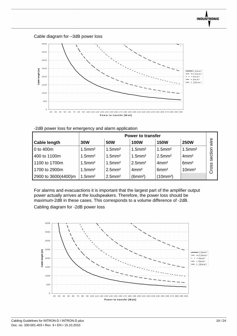
Cable diagram for –3dB power loss
0
5 0 0
1 0 0 0
1 5 0 0
2 0 0 0
2 5 0 0
3 0 0 0
3 5 0 0
4 0 0 0
2 0 3 0 4 0 5 0 6 0 7 0 8 0 9 0 1 0 0 1 1 0 1 2 0 1 3 0 1 4 0 1 5 0 1 6 0 1 7 0 1 8 0 1 9 0 2 0 0 2 1 0 2 2 0 2 3 0 2 4 0 2 5 0 2 6 0 2 7 0 2 8 0 2 9 0 3 0 0
P o w e r to t ra n s fe r [W a tt ]
Cab
le le
ngth
[m]
1 ,5 m m ²2 ,5 m m ²4 m m ²6 m m ²1 0 m m ²
-2dB power loss for emergency and alarm application
Power to transfer Cable length 30W 50W 100W 150W 250W 0 to 400m 1.5mm² 1.5mm² 1.5mm² 1.5mm² 1.5mm² 400 to 1100m 1.5mm² 1.5mm² 1.5mm² 2.5mm² 4mm² 1100 to 1700m 1.5mm² 1.5mm² 2.5mm² 4mm² 6mm² 1700 to 2900m 1.5mm² 2.5mm² 4mm² 6mm² 10mm² 2900 to 3600(4400)m 1.5mm² 2.5mm² (6mm²) (10mm²)
Cro
ss s
ectio
n w
ire
For alarms and evacuactions it is important that the largest part of the amplifier output power actually arrives at the loudspeakers. Therefore, the power loss should be maximum-2dB in these cases. This corresponds to a volume difference of -2dB. Cabling diagram for -2dB power loss
0
500
1000
1500
2000
2500
3000
3500
4000
20 30 40 50 60 70 80 90 100 110 120 130 140 150 160 170 180 190 200 210 220 230 240 250 260 270 280 290 300
P o w e r to tra n s fe r [W a tt]
Cab
le le
ngth
[m]
1 ,5m m ²2 ,5m m ²4m m ²6m m ²10m m ²
Cabling Guidelines for INTRON-D / INTRON-D plus 19 / 24 Doc. no. 330-001-403 • Rev. 9 • EN • 15.10.2010
8 Gland Sizes and Cable Data
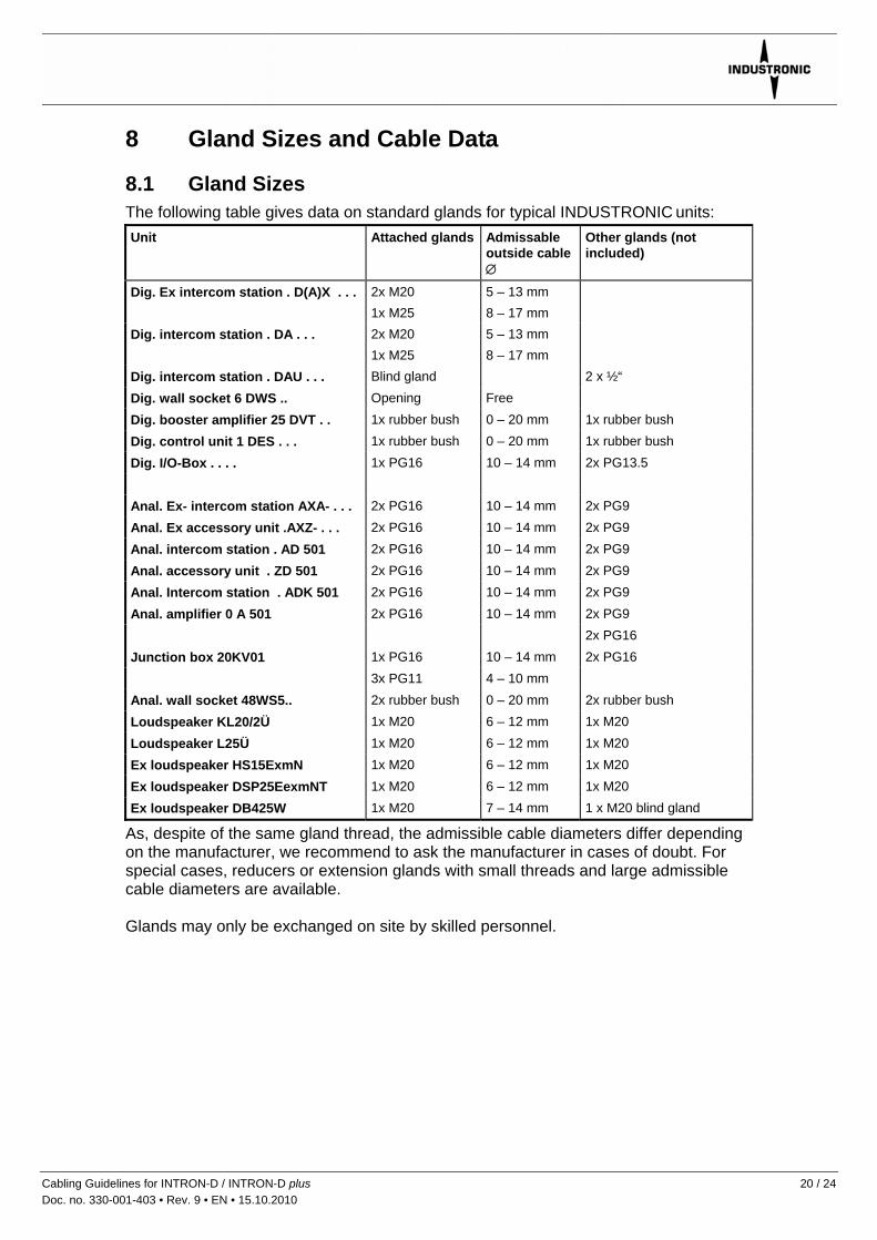
8.1 Gland Sizes The following table gives data on standard glands for typical INDUSTRONIC units: Unit Attached glands Admissable
outside cable ∅
Other glands (not included)
Dig. Ex intercom station . D(A)X . . . 2x M20 1x M25
5 – 13 mm 8 – 17 mm
Dig. intercom station . DA . . . 2x M20 1x M25
5 – 13 mm 8 – 17 mm
Dig. intercom station . DAU . . . Blind gland 2 x ½“ Dig. wall socket 6 DWS .. Opening Free Dig. booster amplifier 25 DVT . . 1x rubber bush 0 – 20 mm 1x rubber bush Dig. control unit 1 DES . . . 1x rubber bush 0 – 20 mm 1x rubber bush Dig. I/O-Box . . . . 1x PG16 10 – 14 mm 2x PG13.5 Anal. Ex- intercom station AXA- . . . 2x PG16 10 – 14 mm 2x PG9 Anal. Ex accessory unit .AXZ- . . . 2x PG16 10 – 14 mm 2x PG9 Anal. intercom station . AD 501 2x PG16 10 – 14 mm 2x PG9 Anal. accessory unit . ZD 501 2x PG16 10 – 14 mm 2x PG9 Anal. Intercom station . ADK 501 2x PG16 10 – 14 mm 2x PG9 Anal. amplifier 0 A 501 2x PG16 10 – 14 mm 2x PG9 2x PG16 Junction box 20KV01 1x PG16 10 – 14 mm 2x PG16 3x PG11 4 – 10 mm Anal. wall socket 48WS5.. 2x rubber bush 0 – 20 mm 2x rubber bush Loudspeaker KL20/2Ü 1x M20 6 – 12 mm 1x M20 Loudspeaker L25Ü 1x M20 6 – 12 mm 1x M20 Ex loudspeaker HS15ExmN 1x M20 6 – 12 mm 1x M20 Ex loudspeaker DSP25EexmNT 1x M20 6 – 12 mm 1x M20 Ex loudspeaker DB425W 1x M20 7 – 14 mm 1 x M20 blind gland
As, despite of the same gland thread, the admissible cable diameters differ depending on the manufacturer, we recommend to ask the manufacturer in cases of doubt. For special cases, reducers or extension glands with small threads and large admissible cable diameters are available. Glands may only be exchanged on site by skilled personnel.
Cabling Guidelines for INTRON-D / INTRON-D plus 20 / 24 Doc. no. 330-001-403 • Rev. 9 • EN • 15.10.2010
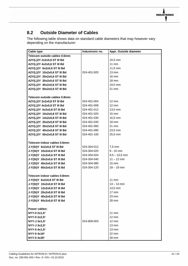
8.2 Outside Diameter of Cables The following table shows data on standard cable diameters that may however vary depending on the manufacturer: Cable type Industronic no. Appr. Outside diameter Telecom outside cables 0.6mm: A2Y(L)2Y 2x2x0,6 ST III Bd 10,5 mm A2Y(L)2Y 4x2x0,6 ST III Bd 11 mm A2Y(L)2Y 6x2x0,6 ST III Bd 11,5 mm A2Y(L)2Y 10x2x0,6 ST III Bd 024-401-920 13 mm A2Y(L)2Y 20x2x0,6 ST III Bd 16 mm A2Y(L)2Y 30x2x0,6 ST III Bd 18 mm A2Y(L)2Y 40x2x0,6 ST III Bd 19,5 mm A2Y(L)2Y 50x2x0,6 ST III Bd 21 mm Telecom outside cables 0.8mm: A2Y(L)2Y 2x2x0,8 ST III Bd 024-401-004 12 mm A2Y(L)2Y 4x2x0,8 ST III Bd 024-401-008 12 mm A2Y(L)2Y 6x2x0,8 ST III Bd 024-401-012 13,5 mm A2Y(L)2Y 10x2x0,8 ST III Bd 024-401-020 15 mm A2Y(L)2Y 14x2x0,8 ST III Bd 024-401-030 16,5 mm A2Y(L)2Y 20x2x0,8 ST III Bd 024-401-040 18 mm A2Y(L)2Y 30x2x0,8 ST III Bd 024-401-060 21 mm A2Y(L)2Y 40x2x0,8 ST III Bd 024-401-080 23,5 mm A2Y(L)2Y 50x2x0,8 ST III Bd 024-401-100 25,5 mm Telecom indoor cables 0.6mm: J-Y(St)Y 6x2x0,6 ST III Bd 024-304-012 7,5 mm J-Y(St)Y 10x2x0,6 ST III Bd 024-304-020 9 - 10 mm J-Y(St)Y 12x2x0,6 ST III Bd 024-304-024 9,5 – 10,5 mm J-Y(St)Y 20x2x0,6 ST III Bd 024-304-040 11 – 12 mm J-Y(St)Y 40x2x0,6 ST III Bd 024-304-080 15 mm J-Y(St)Y 60x2x0,6 ST III Bd 024-304-120 18 – 19 mm Telecom indoor cables 0.8mm: J-Y(St)Y 6x2x0,8 ST III Bd 11 mm J-Y(St)Y 10x2x0,8 ST III Bd 13 – 14 mm J-Y(St)Y 12x2x0,8 ST III Bd 14,5 mm J-Y(St)Y 20x2x0,8 ST III Bd 17 mm J-Y(St)Y 40x2x0,8 ST III Bd 23 mm J-Y(St)Y 60x2x0,8 ST III Bd 28 mm Power cables: NYY-0 2x1,5² 11 mm NYY-0 2x2,5² 12 mm NYY-J 3x1,5² 024-809-003 12 mm NYY-J 3x2,5² 13 mm NYY-0 4x1,5² 13 mm NYY-0 4x16² 22 mm NYY-0 4x35² 28 mm
Cabling Guidelines for INTRON-D / INTRON-D plus 21 / 24 Doc. no. 330-001-403 • Rev. 9 • EN • 15.10.2010

8.3 Wire Diameter / Wire Cross Section Cables for INDUSTRONIC intercom stations should be dimensioned with wires of ≥ 0.8 mm diameter as this increases the maximum line length. Wires with diameters of 0.6 mm can be used, too, but reduce the maximum possible cable lengths. In this respect, please, also note the guidelines no. 330-001-015 regarding the necessary wiring between central exchange units and intercom stations. Please, further note the German rules for designating permanently installed cables: If not indicated otherwise, wire sizes of <1 refer to the diameter in mm, and wire sizes ≥ 1 to the wire cross section (=(d/2)² x π) in mm². Example: A cable with the designation A2Y(L)2Y 6x2x0,8 has wires of 0.8 mm diameter which corresponds to cross sections of appr. 0.5 mm² (=(d/2)² x π). Wires with diameters of 0.6 mm have a cross section of appr. 0.28 mm². The cable designation NYY-0 2x1.5 refers to the wires’ cross section, i.e. 1.5 mm².
8.4 Technical Data on Telecom Cables The following data are typical for telecom cables to INDUSTRONIC intercom stations. These values should also tried to be achieved when using non-European standard cables: Data A2Y(L)2Y .. x2x0.6 A2Y(L)2Y .. x2x0.8 J-Y(St)2Y .. x2x0.6 J-Y(St)2Y .. x2x0.8
Structure Star quad Star quad Twisted pair Twisted pair
Minimum bending radius with permanent installation
10x cable diameter 10x cable diameter 10x cable diameter 10x cable diameter
Temperature range when laying when laid
-5°C up to +50°C ≤ +70°C
-20°C up to +50°C ≤ +70°C
-5°C up to +70°C -5°C up to +70°C
-5°C up to +70°C -5°C up to +70°C
Peak operating voltage (not applicable for high-voltage currents)
225V
225V
300V
300V
Test voltage wire/wire wire/shielding
500V 2000V
500V 2000V
800V 800V
800V 800V
Conductor diameter 0.6mm 0.8mm 0.6mm 0.8mm
Conductor cross section 0.28mm² 0.50mm² 0.28mm² 0.50mm²
Attenuation with 800 Hz 1.0dB/km 0.8dB/km 1.7dB/km 1.1dB/km
Capacitive coupling K1 98% < 400pF/300m 98% < 400pF/300m 80% < 300pF/100m 80% < 300pF/100m
Capacitive coupling K9-12 98% < 100pF/300m 98% < 100pF/300m 90% < 100pF/100m 90% < 100pF/100m
Operating capacity with 800 Hz 52nF/km 52nF/km 100nF/km 100nF/km
Insulation: specific volume resistance
5GΩxkm
5GΩxkm
100MΩxkm
100MΩxkm
Loop resistance 130Ω/km 73,2Ω/km 130Ω/km 73,2Ω/km
VDE norm VDE 0816 VDE 0816 VDE 0815 VDE 0815
Applications
underground laying, laying in conduits, not in potentially fiery areas
underground laying, laying in conduits, not in potentially fiery areas
in dry and moist rooms for permanent installation on the surface as well as buried
in dry and moist rooms for permanent installation on the surface as well as buried
Impedance with 800Hz ≈ 720Ω ≈ 520Ω - -
Cabling Guidelines for INTRON-D / INTRON-D plus 22 / 24 Doc. no. 330-001-403 • Rev. 9 • EN • 15.10.2010

Cabling Guidelines for INTRON-D / INTRON-D plus 23 / 24 Doc. no. 330-001-403 • Rev. 9 • EN • 15.10.2010
9 Conversion into Anglo-American Dimensions (AWG)
Dimensions for copper conductors based on the US American system are normally given as AWG numbers. Please, find following an excerpt including the most important AWB conversion measures:
AWG no. Diameter Cross section
AWG no. Diameter Cross section
1 7.35 mm 42.4 mm² 12 2.05 mm 3.31 mm² 2 6.54 mm 33.6 mm² 14 1.63 mm 2.08 mm² 4 5.19 mm 21.2 mm² 16 1.29 mm 1.31 mm² 6 4.12 mm 13.3 mm² 18 1.024 mm 0.823 mm² 8 3.26 mm 8.37 mm² 20 0.813 mm 0.519 mm² 10 2.59 mm 5.26 mm² 22 0.643 mm 0.324 mm²
Other conversion factors for general/electrical measures:
Anglo-American measure
European conversion (SI units)
Anglo-American measure
European conversion (SI units)
1 inch (in. ‘’) 25.4 mm 1 pF per foot 3.28 pF/m 1 foot 0.305 m 1 μF per mile 0.62 μF/km 1 yard 0.914 m 1 megohm per mile 0.62 MΩ/km 1 mile 1.61 km 1 decibel per mile 0.62 dB/km 1 MCM 0.5067 mm² 1 ohm per 1000 ft 3.28 Ω/km 1 square inch 645.16 mm² 1 ohm per yard 10.936 Ω/km 1 pound (lb) 0.454 kg
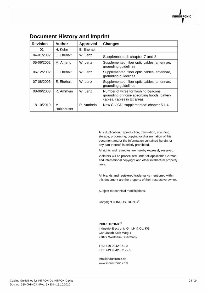
Document History and Imprint Revision Author Approved Changes
01 H. Kuhn E. Ehehalt 04-01/2002 E. Ehehalt W. Lenz Supplemented: chapter 7 and 8 05-06/2002 M. Amend W. Lenz Supplemented: fiber optic cables, antennae,
grounding guidelines 06-12/2002 E. Ehehalt W. Lenz Supplemented: fiber optic cables, antennae,
grounding guidelines 07-08/2005 E. Ehehalt W. Lenz Supplemented: fiber optic cables, antennae,
grounding guidelines 08-06/2008 R. Amrhein W. Lenz Number of wires for flashing beacons,
grounding of noise absorbing hoods, battery cables, cables in Ex areas
18-10/2010 M. Holzhäuser
R. Amrhein New CI / CD; supplemented: chapter 5.1.4
Any duplication, reproduction, translation, scanning, storage, processing, copying or dissemination of this document and/or the information contained herein, or any part thereof, is strictly prohibited.
All rights and remedies are hereby expressly reserved.
Violators will be prosecuted under all applicable German and international copyright and other intellectual property laws.
All brands and registered trademarks mentioned within this document are the property of their respective owner.
Subject to technical modifications.
Copyright © INDUSTRONIC®
INDUSTRONIC® Industrie-Electronic GmbH & Co. KG Carl-Jacob-Kolb-Weg 1 97877 Wertheim / Germany Tel.: +49 9342 871-0 Fax: +49 9342 871-565 [email protected] www.industronic.com
Cabling Guidelines for INTRON-D / INTRON-D plus 24 / 24 Doc. no. 330-001-403 • Rev. 9 • EN • 15.10.2010
Related Documents