CA-7 ® Database Maintenance Guide 3.3

Welcome message from author
This document is posted to help you gain knowledge. Please leave a comment to let me know what you think about it! Share it to your friends and learn new things together.
Transcript

CA-7®Database Maintenance Guide
3.3

This documentation and related computer software program (hereinafter referred to as the “Documentation”) is forthe end user's informational purposes only and is subject to change or withdrawal by Computer Associates Interna-tional, Inc. (“CA”) at any time.
THIS DOCUMENTATION MAY NOT BE COPIED, TRANSFERRED, REPRODUCED, DISCLOSED, ORDUPLICATED, IN WHOLE OR IN PART, WITHOUT THE PRIOR WRITTEN CONSENT OF CA. THIS DOC-UMENTATION IS PROPRIETARY INFORMATION OF CA AND PROTECTED BY THE COPYRIGHT LAWSOF THE UNITED STATES AND INTERNATIONAL TREATIES.
TO THE EXTENT PERMITTED BY APPLICABLE LAW, CA PROVIDES THIS DOCUMENTATION “AS IS”WITHOUT WARRANTY OF ANY KIND, INCLUDING WITHOUT LIMITATION, ANY IMPLIED WARRAN-TIES OF MERCHANTABILITY, FITNESS FOR A PARTICULAR PURPOSE, OR NONINFRINGEMENT. INNO EVENT WILL CA BE LIABLE TO THE END USER OR ANY THIRD PARTY FOR ANY LOSS ORDAMAGE, DIRECT OR INDIRECT, FROM THE USE OF THIS DOCUMENTATION, INCLUDING WITHOUTLIMITATION, LOST PROFITS, BUSINESS INTERRUPTION, GOODWILL, OR LOST DATA, EVEN IF CA ISEXPRESSLY ADVISED OF SUCH LOSS OR DAMAGE.
THE USE OF ANY PRODUCT REFERENCED IN THIS DOCUMENTATION AND THIS DOCUMENTATIONIS GOVERNED BY THE END USER'S APPLICABLE LICENSE AGREEMENT.
The manufacturer of this documentation is Computer Associates International, Inc.
Provided with “Restricted Rights” as set forth in 48 C.F.R. Section 12.212, 48 C.F.R. Sections 52.227-19(c)(1) and(2) or DFARS Section 252.227.7013(c)(1)(ii) or applicable successor provisions.
First Edition, September 2000
1988-2000 Computer Associates International, Inc.One Computer Associates Plaza, Islandia, NY 11749All rights reserved.
All trademarks, trade names, service marks, or logos referenced herein belong to their respective companies.
Contents
Chapter 1. Introduction . . . . . . . . . . . . . . . . . . . . . . . . . . . . . . . . 1-11.1 Summary of Revisions . . . . . . . . . . . . . . . . . . . . . . . . . . . . . . . . 1-2
1.1.1 Product Changes . . . . . . . . . . . . . . . . . . . . . . . . . . . . . . . . 1-21.1.2 Documentation Changes . . . . . . . . . . . . . . . . . . . . . . . . . . . . 1-5
1.2 CA-7 Overview . . . . . . . . . . . . . . . . . . . . . . . . . . . . . . . . . . . . 1-61.3 Functional Overview . . . . . . . . . . . . . . . . . . . . . . . . . . . . . . . . . 1-7
1.3.1 Online Assistance . . . . . . . . . . . . . . . . . . . . . . . . . . . . . . . . 1-71.3.1.1 HELP Facility . . . . . . . . . . . . . . . . . . . . . . . . . . . . . . . 1-71.3.1.2 PF Key Assignment . . . . . . . . . . . . . . . . . . . . . . . . . . . . 1-7
1.3.2 Workload Scheduling . . . . . . . . . . . . . . . . . . . . . . . . . . . . . . 1-81.3.3 Workload Sequencing . . . . . . . . . . . . . . . . . . . . . . . . . . . . . 1-81.3.4 Work Flow Control . . . . . . . . . . . . . . . . . . . . . . . . . . . . . . . 1-81.3.5 Virtual Resource Management . . . . . . . . . . . . . . . . . . . . . . . . . 1-81.3.6 Automated Recovery Facility . . . . . . . . . . . . . . . . . . . . . . . . . 1-91.3.7 Job Restart . . . . . . . . . . . . . . . . . . . . . . . . . . . . . . . . . . . 1-101.3.8 Online Utility Execution . . . . . . . . . . . . . . . . . . . . . . . . . . . 1-101.3.9 Security . . . . . . . . . . . . . . . . . . . . . . . . . . . . . . . . . . . . 1-101.3.10 JCL Overrides . . . . . . . . . . . . . . . . . . . . . . . . . . . . . . . . 1-111.3.11 External Communications Facilities . . . . . . . . . . . . . . . . . . . . 1-111.3.12 Batch Card Load Program . . . . . . . . . . . . . . . . . . . . . . . . . 1-111.3.13 Workload Forecasting . . . . . . . . . . . . . . . . . . . . . . . . . . . . 1-111.3.14 Workload Planning . . . . . . . . . . . . . . . . . . . . . . . . . . . . . 1-121.3.15 Workload Balancing . . . . . . . . . . . . . . . . . . . . . . . . . . . . . 1-121.3.16 Workload Documentation . . . . . . . . . . . . . . . . . . . . . . . . . . 1-121.3.17 Management Level Reporting . . . . . . . . . . . . . . . . . . . . . . . 1-13
1.3.17.1 Automated Performance Analysis (APA) Reporting . . . . . . . . . 1-131.3.17.2 History Reporting . . . . . . . . . . . . . . . . . . . . . . . . . . . 1-131.3.17.3 CA-Earl Reporting . . . . . . . . . . . . . . . . . . . . . . . . . . . 1-131.3.17.4 CA-Easytrieve Plus Reporting . . . . . . . . . . . . . . . . . . . . . 1-13
1.3.18 CA-7 Text Editor . . . . . . . . . . . . . . . . . . . . . . . . . . . . . . 1-131.4 Online Input . . . . . . . . . . . . . . . . . . . . . . . . . . . . . . . . . . . . 1-14
1.4.1 PF Keys . . . . . . . . . . . . . . . . . . . . . . . . . . . . . . . . . . . . 1-141.4.2 Formatted Screen Messages . . . . . . . . . . . . . . . . . . . . . . . . . 1-151.4.3 CA-7 Function Menu . . . . . . . . . . . . . . . . . . . . . . . . . . . . . 1-161.4.4 DB Menu Screen . . . . . . . . . . . . . . . . . . . . . . . . . . . . . . . 1-17
1.4.4.1 Usage Notes . . . . . . . . . . . . . . . . . . . . . . . . . . . . . . . 1-171.4.5 Bypassing the Menu . . . . . . . . . . . . . . . . . . . . . . . . . . . . . 1-18
1.4.5.1 Bypassing Secondary Menus . . . . . . . . . . . . . . . . . . . . . . 1-181.4.6 Function Shortcuts . . . . . . . . . . . . . . . . . . . . . . . . . . . . . . 1-19
1.4.6.1 Shortcut Examples . . . . . . . . . . . . . . . . . . . . . . . . . . . . 1-191.4.7 Function Transfer . . . . . . . . . . . . . . . . . . . . . . . . . . . . . . . 1-201.4.8 Aliases for Formatted Screen Functions . . . . . . . . . . . . . . . . . . . 1-20
1.5 Batch Input . . . . . . . . . . . . . . . . . . . . . . . . . . . . . . . . . . . . . 1-221.5.1 Function Shortcuts and Bypassing the Menu . . . . . . . . . . . . . . . . 1-221.5.2 Function Transfer . . . . . . . . . . . . . . . . . . . . . . . . . . . . . . . 1-231.5.3 Aliases for Formatted Screen Functions . . . . . . . . . . . . . . . . . . . 1-23
Contents iii

Chapter 2. Jobs . . . . . . . . . . . . . . . . . . . . . . . . . . . . . . . . . . . . . 2-12.1 Adding a Job . . . . . . . . . . . . . . . . . . . . . . . . . . . . . . . . . . . . . 2-22.2 DB.1 - CPU Job Definition Screen . . . . . . . . . . . . . . . . . . . . . . . . . 2-3
2.2.1 Field Descriptions . . . . . . . . . . . . . . . . . . . . . . . . . . . . . . . . 2-42.2.2 Usage Notes . . . . . . . . . . . . . . . . . . . . . . . . . . . . . . . . . . 2-152.2.3 Batch Input Example . . . . . . . . . . . . . . . . . . . . . . . . . . . . . 2-15
2.3 Changing a Job . . . . . . . . . . . . . . . . . . . . . . . . . . . . . . . . . . . 2-16
Chapter 3. Scheduling . . . . . . . . . . . . . . . . . . . . . . . . . . . . . . . . . 3-13.1 Work Scheduling . . . . . . . . . . . . . . . . . . . . . . . . . . . . . . . . . . . 3-2
3.1.1 Date and Time Scheduling . . . . . . . . . . . . . . . . . . . . . . . . . . . 3-33.1.1.1 Base Calendars . . . . . . . . . . . . . . . . . . . . . . . . . . . . . . . 3-33.1.1.2 Schedule Definition . . . . . . . . . . . . . . . . . . . . . . . . . . . . 3-43.1.1.3 Schedule Resolution . . . . . . . . . . . . . . . . . . . . . . . . . . . . 3-4
3.1.2 Schedule Modifications . . . . . . . . . . . . . . . . . . . . . . . . . . . . . 3-53.1.2.1 Schedule Scan . . . . . . . . . . . . . . . . . . . . . . . . . . . . . . . 3-6
3.1.3 Event Scheduling . . . . . . . . . . . . . . . . . . . . . . . . . . . . . . . . 3-63.1.3.1 Triggers . . . . . . . . . . . . . . . . . . . . . . . . . . . . . . . . . . 3-6
3.1.4 On-Request Scheduling . . . . . . . . . . . . . . . . . . . . . . . . . . . . . 3-73.1.4.1 DEMAND Command . . . . . . . . . . . . . . . . . . . . . . . . . . . 3-73.1.4.2 DMDNW Command . . . . . . . . . . . . . . . . . . . . . . . . . . . . 3-83.1.4.3 RUN Command . . . . . . . . . . . . . . . . . . . . . . . . . . . . . . 3-83.1.4.4 RUNNW Command . . . . . . . . . . . . . . . . . . . . . . . . . . . . 3-8
3.2 Defining Schedules . . . . . . . . . . . . . . . . . . . . . . . . . . . . . . . . . . 3-93.2.1 DB.2 - Scheduling Menu Screen . . . . . . . . . . . . . . . . . . . . . . . . 3-9
3.2.1.1 Usage Notes . . . . . . . . . . . . . . . . . . . . . . . . . . . . . . . 3-103.2.2 DB.2.1 - CPU Job Scheduling Screen . . . . . . . . . . . . . . . . . . . . 3-11
3.2.2.1 Field Descriptions . . . . . . . . . . . . . . . . . . . . . . . . . . . . 3-123.2.2.2 Usage Notes . . . . . . . . . . . . . . . . . . . . . . . . . . . . . . . 3-13
3.2.3 CPU Job Scheduling Parameter Edit Screen . . . . . . . . . . . . . . . . 3-143.2.3.1 Field Descriptions . . . . . . . . . . . . . . . . . . . . . . . . . . . . 3-153.2.3.2 Batch Input Example . . . . . . . . . . . . . . . . . . . . . . . . . . 3-23
3.2.4 DB.2.2 - Input Network Scheduling Screen . . . . . . . . . . . . . . . . . 3-243.2.4.1 Field Descriptions . . . . . . . . . . . . . . . . . . . . . . . . . . . . 3-25
3.2.5 Input Network Scheduling Parameter Edit Screen . . . . . . . . . . . . . 3-273.2.5.1 Field Descriptions . . . . . . . . . . . . . . . . . . . . . . . . . . . . 3-283.2.5.2 Batch Input Example . . . . . . . . . . . . . . . . . . . . . . . . . . 3-35
3.2.6 DB.2.3 - Output Network Scheduling Screen . . . . . . . . . . . . . . . . 3-363.2.6.1 Field Descriptions . . . . . . . . . . . . . . . . . . . . . . . . . . . . 3-373.2.6.2 Usage Notes . . . . . . . . . . . . . . . . . . . . . . . . . . . . . . . 3-38
3.2.7 Output Network Scheduling Parameter Edit Screen . . . . . . . . . . . . 3-393.2.7.1 Field Descriptions . . . . . . . . . . . . . . . . . . . . . . . . . . . . 3-403.2.7.2 Batch Input Example . . . . . . . . . . . . . . . . . . . . . . . . . . 3-42
3.2.8 Trigger Scheduling Screens . . . . . . . . . . . . . . . . . . . . . . . . . 3-433.2.9 DB.2.4 - Job Triggering Screen . . . . . . . . . . . . . . . . . . . . . . . 3-44
3.2.9.1 Usage Notes . . . . . . . . . . . . . . . . . . . . . . . . . . . . . . . 3-443.2.10 DB.2.5 - Input Network Triggering Screen . . . . . . . . . . . . . . . . 3-45
3.2.10.1 Usage Notes . . . . . . . . . . . . . . . . . . . . . . . . . . . . . . 3-453.2.11 DB.2.6 - Data Set Triggering Screen . . . . . . . . . . . . . . . . . . . . 3-46
3.2.11.1 Usage Notes . . . . . . . . . . . . . . . . . . . . . . . . . . . . . . 3-46
iv CA-7 3.3 Database Maintenance Guide
3.2.11.2 Field Descriptions . . . . . . . . . . . . . . . . . . . . . . . . . . . 3-473.2.11.3 Batch Input Example . . . . . . . . . . . . . . . . . . . . . . . . . . 3-51
3.2.12 DB.2.7 - Modification to Resolved Schedule Dates Screen . . . . . . . 3-523.2.12.1 Field Descriptions . . . . . . . . . . . . . . . . . . . . . . . . . . . 3-533.2.12.2 Usage Notes . . . . . . . . . . . . . . . . . . . . . . . . . . . . . . 3-54
3.2.13 DB.2.8 - Base Calendar Maintenance . . . . . . . . . . . . . . . . . . . 3-553.2.13.1 Field Descriptions . . . . . . . . . . . . . . . . . . . . . . . . . . . 3-563.2.13.2 Usage Notes . . . . . . . . . . . . . . . . . . . . . . . . . . . . . . 3-58
Chapter 4. Requirement Definitions . . . . . . . . . . . . . . . . . . . . . . . . . 4-14.1 Execution Requirements and the LOAD Process . . . . . . . . . . . . . . . . . 4-2
4.1.1 Dependence Definition . . . . . . . . . . . . . . . . . . . . . . . . . . . . . 4-24.1.2 Database Definitions . . . . . . . . . . . . . . . . . . . . . . . . . . . . . . 4-24.1.3 Data Set Dependencies . . . . . . . . . . . . . . . . . . . . . . . . . . . . . 4-34.1.4 Other Dependencies . . . . . . . . . . . . . . . . . . . . . . . . . . . . . . . 4-34.1.5 Temporary Predecessors . . . . . . . . . . . . . . . . . . . . . . . . . . . . 4-4
4.2 Satisfying Requirements . . . . . . . . . . . . . . . . . . . . . . . . . . . . . . . 4-54.3 Defining Predecessors and Successors . . . . . . . . . . . . . . . . . . . . . . . 4-6
4.3.1 DB.3 - Job Predecessor/Successor Menu Screen . . . . . . . . . . . . . . . 4-64.3.1.1 Usage Notes . . . . . . . . . . . . . . . . . . . . . . . . . . . . . . . . 4-7
4.3.2 DB.3.1 - Data Set Predecessors Screen . . . . . . . . . . . . . . . . . . . . 4-84.3.2.1 Field Descriptions . . . . . . . . . . . . . . . . . . . . . . . . . . . . . 4-94.3.2.2 Usage Notes . . . . . . . . . . . . . . . . . . . . . . . . . . . . . . . 4-124.3.2.3 Batch Input Example . . . . . . . . . . . . . . . . . . . . . . . . . . 4-12
4.3.3 DB.3.2 - CPU Job Predecessors Screen . . . . . . . . . . . . . . . . . . . 4-134.3.3.1 Field Descriptions . . . . . . . . . . . . . . . . . . . . . . . . . . . . 4-144.3.3.2 Usage Notes . . . . . . . . . . . . . . . . . . . . . . . . . . . . . . . 4-184.3.3.3 Batch Input Example . . . . . . . . . . . . . . . . . . . . . . . . . . 4-18
4.3.4 DB.3.4 - Input/Output Network Tasks Screen . . . . . . . . . . . . . . . 4-194.3.4.1 Field Descriptions . . . . . . . . . . . . . . . . . . . . . . . . . . . . 4-204.3.4.2 Usage Notes . . . . . . . . . . . . . . . . . . . . . . . . . . . . . . . 4-244.3.4.3 Batch Input Example . . . . . . . . . . . . . . . . . . . . . . . . . . 4-24
4.3.5 DB.3.6 - User Memo-Form Predecessors Screen . . . . . . . . . . . . . . 4-254.3.5.1 Field Descriptions . . . . . . . . . . . . . . . . . . . . . . . . . . . . 4-264.3.5.2 Usage Notes . . . . . . . . . . . . . . . . . . . . . . . . . . . . . . . 4-284.3.5.3 Batch Input Example . . . . . . . . . . . . . . . . . . . . . . . . . . 4-28
4.3.6 DB.3.7 - Report IDs Created Screen . . . . . . . . . . . . . . . . . . . . 4-294.3.6.1 Field Descriptions . . . . . . . . . . . . . . . . . . . . . . . . . . . . 4-304.3.6.2 Batch Input Example . . . . . . . . . . . . . . . . . . . . . . . . . . 4-31
Chapter 5. Virtual Resource Management . . . . . . . . . . . . . . . . . . . . . . 5-15.1 Resource Types . . . . . . . . . . . . . . . . . . . . . . . . . . . . . . . . . . . . 5-2
5.1.1 Shared Resources . . . . . . . . . . . . . . . . . . . . . . . . . . . . . . . . 5-25.1.2 Exclusive Resource . . . . . . . . . . . . . . . . . . . . . . . . . . . . . . . 5-25.1.3 Corequisite Resources . . . . . . . . . . . . . . . . . . . . . . . . . . . . . 5-25.1.4 Address Space Resources . . . . . . . . . . . . . . . . . . . . . . . . . . . . 5-25.1.5 Resource Count Resources . . . . . . . . . . . . . . . . . . . . . . . . . . . 5-3
5.2 Handling Resource Conflicts . . . . . . . . . . . . . . . . . . . . . . . . . . . . 5-45.3 VRM Menu Screen . . . . . . . . . . . . . . . . . . . . . . . . . . . . . . . . . . 5-5
5.3.1 Usage Notes . . . . . . . . . . . . . . . . . . . . . . . . . . . . . . . . . . . 5-5
Contents v
5.4 RM.1 Job Resource Management Screen . . . . . . . . . . . . . . . . . . . . . . 5-65.4.1 Field Descriptions . . . . . . . . . . . . . . . . . . . . . . . . . . . . . . . . 5-75.4.2 Batch Input Example . . . . . . . . . . . . . . . . . . . . . . . . . . . . . 5-105.4.3 Critical Path Monitoring Corequisite Resources . . . . . . . . . . . . . . 5-10
5.4.3.1 Example . . . . . . . . . . . . . . . . . . . . . . . . . . . . . . . . . 5-115.4.3.2 Notes . . . . . . . . . . . . . . . . . . . . . . . . . . . . . . . . . . . 5-11
5.5 RM.2 Job/Resource Cross Reference List Screen . . . . . . . . . . . . . . . . 5-125.5.1 Field Descriptions . . . . . . . . . . . . . . . . . . . . . . . . . . . . . . . 5-135.5.2 Batch Input Example . . . . . . . . . . . . . . . . . . . . . . . . . . . . . 5-14
5.6 RM.3 Active Job Resources Display Screen . . . . . . . . . . . . . . . . . . . 5-155.6.1 Field Descriptions . . . . . . . . . . . . . . . . . . . . . . . . . . . . . . . 5-165.6.2 Batch Input Example . . . . . . . . . . . . . . . . . . . . . . . . . . . . . 5-17
5.7 RM.4 Pending Resources Job Display Screen . . . . . . . . . . . . . . . . . . 5-185.7.1 Field Descriptions . . . . . . . . . . . . . . . . . . . . . . . . . . . . . . . 5-195.7.2 Batch Input Example . . . . . . . . . . . . . . . . . . . . . . . . . . . . . 5-19
5.8 RM.5 Jobs Waiting on Resources Screen . . . . . . . . . . . . . . . . . . . . . 5-205.8.1 Field Descriptions . . . . . . . . . . . . . . . . . . . . . . . . . . . . . . . 5-215.8.2 Batch Input Example . . . . . . . . . . . . . . . . . . . . . . . . . . . . . 5-22
5.9 RM.6 Corequisite Resources List Screen . . . . . . . . . . . . . . . . . . . . . 5-235.9.1 Field Descriptions . . . . . . . . . . . . . . . . . . . . . . . . . . . . . . . 5-245.9.2 Batch Input Example . . . . . . . . . . . . . . . . . . . . . . . . . . . . . 5-24
5.10 RM.7 Resource Count Resource Management Screen . . . . . . . . . . . . . 5-255.10.1 Field Descriptions . . . . . . . . . . . . . . . . . . . . . . . . . . . . . . 5-265.10.2 Batch Input Example . . . . . . . . . . . . . . . . . . . . . . . . . . . . 5-27
5.11 VRM Device Control . . . . . . . . . . . . . . . . . . . . . . . . . . . . . . . 5-285.11.1 Overview . . . . . . . . . . . . . . . . . . . . . . . . . . . . . . . . . . . 5-285.11.2 VRM Device Control Functions - Definition Structure . . . . . . . . . . 5-285.11.3 VRM Device Control Functions - Definition Control . . . . . . . . . . . 5-295.11.4 VRM Device Control Functions - Submission Control . . . . . . . . . . 5-315.11.5 VRM Device Control - Activation . . . . . . . . . . . . . . . . . . . . . 5-31
Chapter 6. Automated Recovery Facility . . . . . . . . . . . . . . . . . . . . . . . 6-16.1 Monitoring Exception Conditions . . . . . . . . . . . . . . . . . . . . . . . . . . 6-26.2 Responding to Exception Conditions . . . . . . . . . . . . . . . . . . . . . . . . 6-36.3 Types of Exceptions Recognized by ARF . . . . . . . . . . . . . . . . . . . . . 6-46.4 ARFSET Structure . . . . . . . . . . . . . . . . . . . . . . . . . . . . . . . . . . 6-6
6.4.1 ARF Definition Structure . . . . . . . . . . . . . . . . . . . . . . . . . . . . 6-66.4.2 Filter Criteria . . . . . . . . . . . . . . . . . . . . . . . . . . . . . . . . . . 6-66.4.3 Type Specific Tests . . . . . . . . . . . . . . . . . . . . . . . . . . . . . . . 6-76.4.4 Responses . . . . . . . . . . . . . . . . . . . . . . . . . . . . . . . . . . . . 6-7
6.4.4.1 Types of Responses . . . . . . . . . . . . . . . . . . . . . . . . . . . . 6-86.4.5 Final Disposition . . . . . . . . . . . . . . . . . . . . . . . . . . . . . . . . 6-8
6.5 Implementation Considerations . . . . . . . . . . . . . . . . . . . . . . . . . . . 6-96.6 AR.3 ARF Condition Definition Maintenance Screen . . . . . . . . . . . . . . 6-10
6.6.1 Field Descriptions . . . . . . . . . . . . . . . . . . . . . . . . . . . . . . . 6-106.7 ARF Condition Definition Edit Screen . . . . . . . . . . . . . . . . . . . . . . 6-12
6.7.1 Field Descriptions . . . . . . . . . . . . . . . . . . . . . . . . . . . . . . . 6-136.7.2 Field Descriptions - Filter Criteria . . . . . . . . . . . . . . . . . . . . . . 6-156.7.3 Field Descriptions - Type Specific Tests for JC and SC Conditions . . . 6-19
vi CA-7 3.3 Database Maintenance Guide

6.7.4 Field Descriptions - Type Specific Tests for EC, EE, IS, LB, LE and LSConditions . . . . . . . . . . . . . . . . . . . . . . . . . . . . . . . . . . . . . . 6-23
6.7.5 Field Descriptions - Responses . . . . . . . . . . . . . . . . . . . . . . . 6-276.7.6 Field Descriptions - Final Disposition . . . . . . . . . . . . . . . . . . . . 6-28
6.8 Rules for Coding ARF Action Statements . . . . . . . . . . . . . . . . . . . . 6-316.8.1 AC - Issue a Command . . . . . . . . . . . . . . . . . . . . . . . . . . . . 6-31
6.8.1.1 Example . . . . . . . . . . . . . . . . . . . . . . . . . . . . . . . . . 6-316.8.2 AM - Issue a Message . . . . . . . . . . . . . . . . . . . . . . . . . . . . 6-32
6.8.2.1 Examples . . . . . . . . . . . . . . . . . . . . . . . . . . . . . . . . . 6-336.8.3 AW - Wait . . . . . . . . . . . . . . . . . . . . . . . . . . . . . . . . . . 6-34
6.8.3.1 Example . . . . . . . . . . . . . . . . . . . . . . . . . . . . . . . . . 6-346.8.4 AJ - Schedule a Recovery Job . . . . . . . . . . . . . . . . . . . . . . . . 6-35
6.8.4.1 Example . . . . . . . . . . . . . . . . . . . . . . . . . . . . . . . . . 6-366.9 Using Reserved Words in Type Specific Tests . . . . . . . . . . . . . . . . . . 6-376.10 Using Variables in ARF Action Statements . . . . . . . . . . . . . . . . . . . 6-396.11 Examples of ARF Condition Definition . . . . . . . . . . . . . . . . . . . . . 6-40
6.11.1 Defining a Job Completion Condition (JC) . . . . . . . . . . . . . . . . 6-406.11.2 Defining a Late at Job End Notification (LE) . . . . . . . . . . . . . . . 6-42
Chapter 7. Workload Documentation . . . . . . . . . . . . . . . . . . . . . . . . . 7-17.1 Workload Documentation Screens . . . . . . . . . . . . . . . . . . . . . . . . . 7-2
7.1.1 DB.4 Menu Screen . . . . . . . . . . . . . . . . . . . . . . . . . . . . . . . 7-37.1.1.1 Usage Notes . . . . . . . . . . . . . . . . . . . . . . . . . . . . . . . . 7-3
7.1.2 DB.4.1 - CPU Job Documentation Screen . . . . . . . . . . . . . . . . . . 7-47.1.2.1 Field Descriptions . . . . . . . . . . . . . . . . . . . . . . . . . . . . . 7-5
7.1.3 DB.4.2 - Input/Output Network Documentation Screen . . . . . . . . . . . 7-77.1.3.1 Field Descriptions . . . . . . . . . . . . . . . . . . . . . . . . . . . . . 7-8
7.1.4 DB.4.3 - User-Defined Item Documentation Screen . . . . . . . . . . . . 7-117.1.4.1 Field Descriptions . . . . . . . . . . . . . . . . . . . . . . . . . . . . 7-12
7.1.5 DB.4.4 - Data Set Documentation Screen . . . . . . . . . . . . . . . . . . 7-157.1.5.1 Field Descriptions . . . . . . . . . . . . . . . . . . . . . . . . . . . . 7-16
7.1.6 DB.4.5 - DD Statement Documentation Screen . . . . . . . . . . . . . . . 7-197.1.6.1 Field Descriptions . . . . . . . . . . . . . . . . . . . . . . . . . . . . 7-20
7.1.7 DB.4.6 - Application System Documentation Screen . . . . . . . . . . . . 7-237.1.7.1 Field Descriptions . . . . . . . . . . . . . . . . . . . . . . . . . . . . 7-24
7.2 Special Documentation Features . . . . . . . . . . . . . . . . . . . . . . . . . 7-267.2.1 User-Defined Documentation Segments . . . . . . . . . . . . . . . . . . . 7-26
7.2.1.1 Reserved Segment Names . . . . . . . . . . . . . . . . . . . . . . . . 7-267.2.1.2 Rules and Guidelines for Documentation Segmentation . . . . . . . 7-267.2.1.3 Defining Segment Names . . . . . . . . . . . . . . . . . . . . . . . . 7-277.2.1.4 Format of Documentation Segments . . . . . . . . . . . . . . . . . . 7-277.2.1.5 Displaying Documentation Segments . . . . . . . . . . . . . . . . . . 7-287.2.1.6 Subsegments . . . . . . . . . . . . . . . . . . . . . . . . . . . . . . . 7-297.2.1.7 Rules and Guidelines for Subsegments . . . . . . . . . . . . . . . . . 7-297.2.1.8 Defining Subsegment Names . . . . . . . . . . . . . . . . . . . . . . 7-297.2.1.9 Format of Documentation Subsegments . . . . . . . . . . . . . . . . 7-307.2.1.10 Displaying Documentation Subsegments . . . . . . . . . . . . . . . 7-317.2.1.11 Documenting Naming Conventions . . . . . . . . . . . . . . . . . . 7-32
7.2.2 Special Purpose Documentation . . . . . . . . . . . . . . . . . . . . . . . 7-337.2.2.1 General Format . . . . . . . . . . . . . . . . . . . . . . . . . . . . . 7-33
Contents vii
7.2.3 #QDESC Segment Usage . . . . . . . . . . . . . . . . . . . . . . . . . . . 7-347.2.4 #station-name Segment Usage . . . . . . . . . . . . . . . . . . . . . . . . 7-357.2.5 #RESTART Segment Usage . . . . . . . . . . . . . . . . . . . . . . . . . 7-367.2.6 #END Statement . . . . . . . . . . . . . . . . . . . . . . . . . . . . . . . 7-37
Chapter 8. Workstation Networks . . . . . . . . . . . . . . . . . . . . . . . . . . 8-18.1 Adding a Network . . . . . . . . . . . . . . . . . . . . . . . . . . . . . . . . . . 8-28.2 DB.5 - Input/Output Network Definition Screen . . . . . . . . . . . . . . . . . . 8-3
8.2.1.1 Field Descriptions . . . . . . . . . . . . . . . . . . . . . . . . . . . . . 8-48.2.1.2 Batch Input Example . . . . . . . . . . . . . . . . . . . . . . . . . . . 8-5
8.3 Changing a Network . . . . . . . . . . . . . . . . . . . . . . . . . . . . . . . . . 8-6
Chapter 9. Data Sets . . . . . . . . . . . . . . . . . . . . . . . . . . . . . . . . . . 9-19.1 Adding a Data Set . . . . . . . . . . . . . . . . . . . . . . . . . . . . . . . . . . 9-2
9.1.1 Permanent Data Sets . . . . . . . . . . . . . . . . . . . . . . . . . . . . . . 9-39.1.2 Dynamically Allocated Data Sets . . . . . . . . . . . . . . . . . . . . . . . 9-49.1.3 External Data Sets . . . . . . . . . . . . . . . . . . . . . . . . . . . . . . . 9-4
9.2 DB.6 - Data Set Definition Screen . . . . . . . . . . . . . . . . . . . . . . . . . 9-59.2.1.1 Field Descriptions . . . . . . . . . . . . . . . . . . . . . . . . . . . . . 9-69.2.1.2 Usage Notes . . . . . . . . . . . . . . . . . . . . . . . . . . . . . . . . 9-99.2.1.3 Batch Input Example . . . . . . . . . . . . . . . . . . . . . . . . . . . 9-9
9.3 Changing a Data Set . . . . . . . . . . . . . . . . . . . . . . . . . . . . . . . . 9-10
Chapter 10. JCL Management . . . . . . . . . . . . . . . . . . . . . . . . . . . 10-110.1 DB.7 - JCL Library Maintenance Screen . . . . . . . . . . . . . . . . . . . . 10-2
10.1.1 Field Descriptions . . . . . . . . . . . . . . . . . . . . . . . . . . . . . . 10-310.1.2 Usage Notes . . . . . . . . . . . . . . . . . . . . . . . . . . . . . . . . . 10-5
10.2 Scheduled Overrides . . . . . . . . . . . . . . . . . . . . . . . . . . . . . . . 10-610.2.1 #JI and #JO Statements . . . . . . . . . . . . . . . . . . . . . . . . . . . 10-7
10.2.1.1 Syntax . . . . . . . . . . . . . . . . . . . . . . . . . . . . . . . . . . 10-710.2.2 #JEND Statement . . . . . . . . . . . . . . . . . . . . . . . . . . . . . 10-10
10.2.2.1 Syntax . . . . . . . . . . . . . . . . . . . . . . . . . . . . . . . . . 10-1010.2.2.2 Usage Notes . . . . . . . . . . . . . . . . . . . . . . . . . . . . . 10-10
10.2.3 #XI, #XO, and #XEND Statements . . . . . . . . . . . . . . . . . . . 10-1010.2.4 Scheduled Override Examples . . . . . . . . . . . . . . . . . . . . . . 10-11
10.3 Additional Override Statements . . . . . . . . . . . . . . . . . . . . . . . . 10-1310.3.1 #ARF Statement . . . . . . . . . . . . . . . . . . . . . . . . . . . . . . 10-14
10.3.1.1 Syntax . . . . . . . . . . . . . . . . . . . . . . . . . . . . . . . . . 10-1410.3.1.2 Example . . . . . . . . . . . . . . . . . . . . . . . . . . . . . . . . 10-1410.3.1.3 Usage Notes . . . . . . . . . . . . . . . . . . . . . . . . . . . . . 10-15
10.3.2 #MSG Statement . . . . . . . . . . . . . . . . . . . . . . . . . . . . . . 10-1610.3.2.1 Syntax . . . . . . . . . . . . . . . . . . . . . . . . . . . . . . . . . 10-1610.3.2.2 Usage Notes . . . . . . . . . . . . . . . . . . . . . . . . . . . . . 10-16
10.3.3 #RES Statement . . . . . . . . . . . . . . . . . . . . . . . . . . . . . . 10-1710.3.3.1 Syntax . . . . . . . . . . . . . . . . . . . . . . . . . . . . . . . . . 10-17
10.3.4 #SCC Statement . . . . . . . . . . . . . . . . . . . . . . . . . . . . . . 10-1810.3.4.1 Syntax . . . . . . . . . . . . . . . . . . . . . . . . . . . . . . . . . 10-1810.3.4.2 Example . . . . . . . . . . . . . . . . . . . . . . . . . . . . . . . . 10-1910.3.4.3 Usage Notes . . . . . . . . . . . . . . . . . . . . . . . . . . . . . 10-20
10.3.5 Additional Override Examples . . . . . . . . . . . . . . . . . . . . . . 10-21
viii CA-7 3.3 Database Maintenance Guide
10.4 SASSJCLU - JCL Utility . . . . . . . . . . . . . . . . . . . . . . . . . . . . 10-2410.4.1 Usage Notes . . . . . . . . . . . . . . . . . . . . . . . . . . . . . . . . 10-25
10.4.1.1 Control Statement . . . . . . . . . . . . . . . . . . . . . . . . . . 10-2510.4.1.2 JCL . . . . . . . . . . . . . . . . . . . . . . . . . . . . . . . . . . 10-26
10.5 JCL Validation . . . . . . . . . . . . . . . . . . . . . . . . . . . . . . . . . 10-2710.6 LOAD Command Processing . . . . . . . . . . . . . . . . . . . . . . . . . 10-2810.7 Special Override Library . . . . . . . . . . . . . . . . . . . . . . . . . . . . 10-29
10.7.1 Defining a Special Override Library . . . . . . . . . . . . . . . . . . . 10-2910.7.2 Creating Temporary JCL . . . . . . . . . . . . . . . . . . . . . . . . . 10-2910.7.3 Using Temporary JCL . . . . . . . . . . . . . . . . . . . . . . . . . . . 10-3010.7.4 Other Considerations . . . . . . . . . . . . . . . . . . . . . . . . . . . 10-30
10.8 Alternate JCL Libraries . . . . . . . . . . . . . . . . . . . . . . . . . . . . . 10-3110.8.1 Defining an Alternate Library . . . . . . . . . . . . . . . . . . . . . . 10-3110.8.2 Creating Temporary JCL . . . . . . . . . . . . . . . . . . . . . . . . . 10-3110.8.3 Using Temporary JCL . . . . . . . . . . . . . . . . . . . . . . . . . . . 10-3110.8.4 Other Considerations . . . . . . . . . . . . . . . . . . . . . . . . . . . 10-32
Chapter 11. Edit Facility . . . . . . . . . . . . . . . . . . . . . . . . . . . . . . . 11-111.1 Active Area . . . . . . . . . . . . . . . . . . . . . . . . . . . . . . . . . . . . 11-311.2 Edit Work File . . . . . . . . . . . . . . . . . . . . . . . . . . . . . . . . . . 11-411.3 Environments . . . . . . . . . . . . . . . . . . . . . . . . . . . . . . . . . . . 11-511.4 Using the Editor . . . . . . . . . . . . . . . . . . . . . . . . . . . . . . . . . . 11-6
11.4.1 Invoking the Editor . . . . . . . . . . . . . . . . . . . . . . . . . . . . . 11-611.4.2 Editing Text Data . . . . . . . . . . . . . . . . . . . . . . . . . . . . . . 11-611.4.3 Leaving the Editor . . . . . . . . . . . . . . . . . . . . . . . . . . . . . . 11-7
11.5 CA-7 Text Editor Environment . . . . . . . . . . . . . . . . . . . . . . . . . 11-811.5.1 Edit Modes . . . . . . . . . . . . . . . . . . . . . . . . . . . . . . . . . . 11-8
11.5.1.1 Usage Considerations . . . . . . . . . . . . . . . . . . . . . . . . . 11-811.5.1.2 Full Edit Mode (FEM) . . . . . . . . . . . . . . . . . . . . . . . . . 11-9
11.5.2 Updating Text . . . . . . . . . . . . . . . . . . . . . . . . . . . . . . . 11-2711.5.3 Creating Text . . . . . . . . . . . . . . . . . . . . . . . . . . . . . . . 11-2811.5.4 Special Considerations . . . . . . . . . . . . . . . . . . . . . . . . . . 11-29
11.5.4.1 PF/PA Key Usage . . . . . . . . . . . . . . . . . . . . . . . . . . 11-2911.5.4.2 Character Translation . . . . . . . . . . . . . . . . . . . . . . . . 11-2911.5.4.3 Nondisplayable Data (hex) . . . . . . . . . . . . . . . . . . . . . . 11-29
11.6 TSO/ISPF Editor Environment . . . . . . . . . . . . . . . . . . . . . . . . . 11-3011.6.1 Requesting CA-7 Edit Functions from the ISPF Editor . . . . . . . . . 11-3111.6.2 Default Requests for CA-7 Edit Functions . . . . . . . . . . . . . . . . 11-3211.6.3 Special Considerations . . . . . . . . . . . . . . . . . . . . . . . . . . 11-34
11.6.3.1 ISPF Edit Profile Settings . . . . . . . . . . . . . . . . . . . . . . 11-3411.6.3.2 PF/PA Key Usage . . . . . . . . . . . . . . . . . . . . . . . . . . 11-3411.6.3.3 SUBMIT Function . . . . . . . . . . . . . . . . . . . . . . . . . . 11-3411.6.3.4 Size of Data . . . . . . . . . . . . . . . . . . . . . . . . . . . . . 11-34
Chapter 12. Database Verification . . . . . . . . . . . . . . . . . . . . . . . . . 12-112.1 Pointer Verification . . . . . . . . . . . . . . . . . . . . . . . . . . . . . . . . 12-2
12.1.1 Pointer Verification Parameters . . . . . . . . . . . . . . . . . . . . . . . 12-212.1.2 Pointer Verification by Record Type . . . . . . . . . . . . . . . . . . . . 12-3
12.1.2.1 Network Directory . . . . . . . . . . . . . . . . . . . . . . . . . . . 12-312.1.2.2 Job Schedule Directory . . . . . . . . . . . . . . . . . . . . . . . . 12-3
Contents ix
12.1.2.3 Data Set Directory . . . . . . . . . . . . . . . . . . . . . . . . . . . 12-412.1.2.4 Documentation Directory . . . . . . . . . . . . . . . . . . . . . . . 12-412.1.2.5 Job Directory . . . . . . . . . . . . . . . . . . . . . . . . . . . . . . 12-412.1.2.6 Data Set Member . . . . . . . . . . . . . . . . . . . . . . . . . . . . 12-412.1.2.7 Network Member . . . . . . . . . . . . . . . . . . . . . . . . . . . . 12-512.1.2.8 Input Network Schedule Member . . . . . . . . . . . . . . . . . . . 12-512.1.2.9 Output Network Schedule Member . . . . . . . . . . . . . . . . . . 12-512.1.2.10 Documentation Member . . . . . . . . . . . . . . . . . . . . . . . 12-512.1.2.11 Job Member . . . . . . . . . . . . . . . . . . . . . . . . . . . . . . 12-5
12.2 Analyze Commands . . . . . . . . . . . . . . . . . . . . . . . . . . . . . . . . 12-6
Chapter 13. Database Transportability . . . . . . . . . . . . . . . . . . . . . . . 13-113.1 Assumptions . . . . . . . . . . . . . . . . . . . . . . . . . . . . . . . . . . . . 13-3
13.1.1 LOAD/RELOAD Status . . . . . . . . . . . . . . . . . . . . . . . . . . . 13-413.1.2 CA-11 Step Insertion . . . . . . . . . . . . . . . . . . . . . . . . . . . . 13-413.1.3 Base Calendars . . . . . . . . . . . . . . . . . . . . . . . . . . . . . . . . 13-413.1.4 Calendar Schedules . . . . . . . . . . . . . . . . . . . . . . . . . . . . . 13-413.1.5 DB.2.7 Schedule Modifications . . . . . . . . . . . . . . . . . . . . . . . 13-413.1.6 NXTCYC Settings . . . . . . . . . . . . . . . . . . . . . . . . . . . . . . 13-513.1.7 Execution JCL Libraries . . . . . . . . . . . . . . . . . . . . . . . . . . 13-513.1.8 Cataloged Procedures . . . . . . . . . . . . . . . . . . . . . . . . . . . . 13-513.1.9 In-stream JCL Procedures . . . . . . . . . . . . . . . . . . . . . . . . . . 13-613.1.10 Workstation Networks . . . . . . . . . . . . . . . . . . . . . . . . . . . 13-613.1.11 User Level Documentation . . . . . . . . . . . . . . . . . . . . . . . . 13-613.1.12 ANALYZE Application . . . . . . . . . . . . . . . . . . . . . . . . . . 13-613.1.13 Commas in the Data . . . . . . . . . . . . . . . . . . . . . . . . . . . . 13-613.1.14 Sequence Numbers . . . . . . . . . . . . . . . . . . . . . . . . . . . . . 13-713.1.15 User ID Security . . . . . . . . . . . . . . . . . . . . . . . . . . . . . . 13-713.1.16 LINKed Documentation . . . . . . . . . . . . . . . . . . . . . . . . . . 13-7
13.2 Database Extraction . . . . . . . . . . . . . . . . . . . . . . . . . . . . . . . . 13-813.3 CPU Jobs . . . . . . . . . . . . . . . . . . . . . . . . . . . . . . . . . . . . 13-13
13.3.1 Adding at New Site . . . . . . . . . . . . . . . . . . . . . . . . . . . . 13-1313.3.2 Requirements and Network Connections . . . . . . . . . . . . . . . . . 13-15
13.3.2.1 JOB Connections . . . . . . . . . . . . . . . . . . . . . . . . . . . 13-1513.3.2.2 NWK Connections . . . . . . . . . . . . . . . . . . . . . . . . . . 13-1513.3.2.3 DSN Connections . . . . . . . . . . . . . . . . . . . . . . . . . . 13-1613.3.2.4 USR Connections . . . . . . . . . . . . . . . . . . . . . . . . . . . 13-16
13.3.3 Deleting at Original Site . . . . . . . . . . . . . . . . . . . . . . . . . 13-1713.3.4 Disabling at Original Site . . . . . . . . . . . . . . . . . . . . . . . . . 13-18
13.4 Workstation Networks . . . . . . . . . . . . . . . . . . . . . . . . . . . . . 13-1913.4.1 Adding at New Site . . . . . . . . . . . . . . . . . . . . . . . . . . . . 13-1913.4.2 Deleting at Original Site . . . . . . . . . . . . . . . . . . . . . . . . . 13-2013.4.3 Disabling at Original Site . . . . . . . . . . . . . . . . . . . . . . . . . 13-21
13.4.3.1 Input Workstation Networks . . . . . . . . . . . . . . . . . . . . . 13-2113.4.3.2 Output Workstation Networks . . . . . . . . . . . . . . . . . . . . 13-21
13.4.4 Unconnected Workstation Networks . . . . . . . . . . . . . . . . . . . 13-2113.5 Application Data Sets . . . . . . . . . . . . . . . . . . . . . . . . . . . . . . 13-22
13.5.1 Adding at New Site . . . . . . . . . . . . . . . . . . . . . . . . . . . . 13-2213.5.2 Deleting at Original Site . . . . . . . . . . . . . . . . . . . . . . . . . 13-23
13.6 PDS JCL Members . . . . . . . . . . . . . . . . . . . . . . . . . . . . . . . 13-24
x CA-7 3.3 Database Maintenance Guide

13.6.1 Adding at New Site . . . . . . . . . . . . . . . . . . . . . . . . . . . . 13-2413.6.2 Deleting at Original Site . . . . . . . . . . . . . . . . . . . . . . . . . 13-25
13.7 CA-Librarian JCL . . . . . . . . . . . . . . . . . . . . . . . . . . . . . . . . 13-2613.7.1 Adding at New Site . . . . . . . . . . . . . . . . . . . . . . . . . . . . 13-2613.7.2 Deleting at Original Site . . . . . . . . . . . . . . . . . . . . . . . . . 13-28
13.8 CA-Panvalet JCL . . . . . . . . . . . . . . . . . . . . . . . . . . . . . . . . 13-2913.8.1 Adding at New Site . . . . . . . . . . . . . . . . . . . . . . . . . . . . 13-2913.8.2 Disabling at Original Site . . . . . . . . . . . . . . . . . . . . . . . . . 13-31
13.9 Cataloged Procedures . . . . . . . . . . . . . . . . . . . . . . . . . . . . . . 13-3213.9.1 Adding at New Site . . . . . . . . . . . . . . . . . . . . . . . . . . . . 13-3213.9.2 Deleting at Original Site . . . . . . . . . . . . . . . . . . . . . . . . . 13-33
13.10 Documentation . . . . . . . . . . . . . . . . . . . . . . . . . . . . . . . . . 13-3413.10.1 Adding at New Site . . . . . . . . . . . . . . . . . . . . . . . . . . . 13-3413.10.2 Deleting at Original Site . . . . . . . . . . . . . . . . . . . . . . . . . 13-35
13.11 Schedules . . . . . . . . . . . . . . . . . . . . . . . . . . . . . . . . . . . . 13-3613.11.1 Adding at New Site . . . . . . . . . . . . . . . . . . . . . . . . . . . 13-36
13.11.1.1 CPU Job Schedules . . . . . . . . . . . . . . . . . . . . . . . . . 13-3613.11.1.2 Job Triggers . . . . . . . . . . . . . . . . . . . . . . . . . . . . . 13-3713.11.1.3 Network Triggers . . . . . . . . . . . . . . . . . . . . . . . . . . 13-3713.11.1.4 Data Set Triggers . . . . . . . . . . . . . . . . . . . . . . . . . . 13-3713.11.1.5 Input Networks . . . . . . . . . . . . . . . . . . . . . . . . . . . 13-3813.11.1.6 Output Networks . . . . . . . . . . . . . . . . . . . . . . . . . . 13-39
13.11.2 Deleting at Original Site . . . . . . . . . . . . . . . . . . . . . . . . . 13-4013.11.2.1 CPU Job Schedules . . . . . . . . . . . . . . . . . . . . . . . . . 13-4013.11.2.2 Input Network Schedules . . . . . . . . . . . . . . . . . . . . . . 13-4013.11.2.3 Output Network Schedules . . . . . . . . . . . . . . . . . . . . . 13-40
13.12 Creating Command Files . . . . . . . . . . . . . . . . . . . . . . . . . . . 13-4113.12.1 Job 1 . . . . . . . . . . . . . . . . . . . . . . . . . . . . . . . . . . . 13-41
13.12.1.1 PARM Keywords . . . . . . . . . . . . . . . . . . . . . . . . . . 13-4113.12.1.2 Specifying Jobs to Move . . . . . . . . . . . . . . . . . . . . . . 13-4213.12.1.3 Data Sets Used/Created . . . . . . . . . . . . . . . . . . . . . . . 13-43
13.12.2 Job 2 . . . . . . . . . . . . . . . . . . . . . . . . . . . . . . . . . . . 13-4413.12.2.1 PARM Keywords . . . . . . . . . . . . . . . . . . . . . . . . . . 13-4413.12.2.2 Data Sets Used/Created . . . . . . . . . . . . . . . . . . . . . . . 13-44
13.12.3 Job 3 . . . . . . . . . . . . . . . . . . . . . . . . . . . . . . . . . . . 13-4613.12.3.1 PARM Keywords . . . . . . . . . . . . . . . . . . . . . . . . . . 13-4613.12.3.2 Command Data Sets . . . . . . . . . . . . . . . . . . . . . . . . 13-47
13.13 Special Considerations . . . . . . . . . . . . . . . . . . . . . . . . . . . . 13-5013.13.1 Design Limitations . . . . . . . . . . . . . . . . . . . . . . . . . . . . 13-5013.13.2 Adding to the New Database . . . . . . . . . . . . . . . . . . . . . . 13-5113.13.3 Running at New Site . . . . . . . . . . . . . . . . . . . . . . . . . . . 13-5113.13.4 Mass Changes at Existing Site . . . . . . . . . . . . . . . . . . . . . 13-52
13.14 Virtual Resource Management Database Extracts . . . . . . . . . . . . . . 13-5313.14.1 VRM DBT Job Extract JCL . . . . . . . . . . . . . . . . . . . . . . . 13-54
13.14.1.1 PARM Keywords . . . . . . . . . . . . . . . . . . . . . . . . . . 13-5413.14.1.2 SYSIN Control Cards . . . . . . . . . . . . . . . . . . . . . . . . 13-5513.14.1.3 Data Sets Used/Created . . . . . . . . . . . . . . . . . . . . . . . 13-55
13.15 Automated Recovery Facility Database Extracts . . . . . . . . . . . . . . 13-5613.15.1 PARM Keywords . . . . . . . . . . . . . . . . . . . . . . . . . . . . 13-5713.15.2 Data Sets Used/Created . . . . . . . . . . . . . . . . . . . . . . . . . 13-58
Contents xi

Index . . . . . . . . . . . . . . . . . . . . . . . . . . . . . . . . . . . . . . . . . . . X-1
xii CA-7 3.3 Database Maintenance Guide
Chapter 1. Introduction
The CA-7 Database Maintenance Guide is intended for database administrators and/orchange control personnel. It contains information on:
� jobs � scheduling � requirement definitions� virtual resource management� automated recovery facility� workload documentation maintenance
� networks � data sets � JCL management � text editing � database verification � database transportability
Chapter 1. Introduction 1-1
1.1 Summary of Revisions
1.1 Summary of Revisions
This topic explains changes to both CA-7 and to the documentation.
1.1.1 Product Changes
CA-7 Version 3.3 contains the following major enhancements:
� Parallel Sysplex Exploitation
CA-7 can optionally maintain a memory structure in the Coupling Facility in whichparticipating ICOMs record tracking data. One or more Host ICOM(s) read from thememory structure and write to the Communication data set. This can significantlyreduce I/O contention and increase feedback throughput.
� UNIX System Services Interface
The OS/390 UNIX System Services (USS) CA-7 interface allows communicationwith CA-7 from the USS environment. The interface can be called directly from theUNIX shell or from the IBM USS batch interface (BPXBATCH).
� CA-7 CCI Interface
The CA-7 CCI interface allows two-way communication with CA-7 from otheraddress spaces and environments. The interface can be engaged in a batch mode, ina REXX address environment or it can be called directly from a user program. Itaccepts single or stacked commands as input and returns the CA-7 output from thecommands as if they had been executed in batch mode.
� Critical Path Monitoring
Through integration with CA-OPS/MVS II, Unicenter TNG and Unicenter TNGMVS Event Manager Option (MEMO), CA-7 can support the definition and moni-toring of critical job flows within the CA-7 workload. CA-OPS/MVS II providesmanagement and administration of critical path displays.
� Mixed Case Support in CA-7 Editor
Character translation controls can be set in the CA-7 Editor. New Editor subcom-mands 'UPPER' and 'MIXED' determine whether editor data is translated to uppercaseor left "as is."
These subcommands are enabled with a new initialization file option. If this optionis not coded, then all edit data is translated to uppercase.
� Job Completion Tracking Precision
CA-7 records job completion times in hundredths of seconds. This allows job com-pletions to be discriminated with a high degree of precision, thus reducing the likeli-hood of requirement posting ambiguities where jobs complete within the sameminute.
1-2 CA-7 3.3 Database Maintenance Guide
1.1 Summary of Revisions
� Display Duplicate Days for RESOLVe
CA-7 can optionally display the duplicate RESOLV day(s) in new messageSRC1-137. This occurs when a job is scheduled to execute the same day under twoor more different Schedule IDs. With this information one can more quickly andefficiently determine the source of the scheduling conflict.
� VRM Device Control
Virtual Resource Management (VRM) Device Control provides an alternative toWorkload Balancing control of job submission based on tape drive availability.VRM resource count resources representing the number and type of storage devicesused by the job are defined dynamically during CA-7 LOAD processing.
Workload Balancing only permits two types of tape drives. With VRM DeviceControl, the number and structure of device groups is determined by the user.
� CA-7 Command Retrieval
Command line input for CA-7 VTAM terminals is recorded in storage and may beretrieved with the /FETCH command. When the /PFnn command is used to associate/FETCH with a PF key, the CA-7 user can conveniently retrieve the last five CA-7commands entered at an online terminal.
� CA-7 Base Calendar Security
CA-7 security can allow clients to define CA-7 base calendar names to an externalsecurity product and secure user access to individual base calendars.
� REXX Address Environment
Using the new CA-7 CCI interface, CA-7 allows REXX programs to pass commandsto CA-7 and take action based on the output from those commands.
� Job 'Purge' Function
The DB.1 (Job) panel provides a new function, PURGE, which deletes all CA-7 data-base records related to a job. In addition to the standard delete processes, thePURGE function deletes incoming trigger definitions, requirement successor defi-nitions, and the CA-11 CMT member for the job.
� Suppress LATE Designation
Through an Initialization File option, the PROMPTS field on the DB.1 (Job) panelcan be used to indicate certain jobs should never be marked as LATE on status dis-plays. This means operations and production control staff will not be distractedwhen test or non-critical jobs do not complete on time.
� CSA Chains Above the 16M Line
CA-7 CSA SMF and Trailer chains now reside in extended CSA (above-the-line),thereby reducing utilization of this critical resource.
� Automated Recovery Facility (ARF) Enhancements
CA-7 can optionally add a LOGON parameter to the ARF TSO SEND command tocause messages to be retained until the user logs on to TSO. Also, support for ARFhas been added to the Database Transportability facility.
Chapter 1. Introduction 1-3

1.1 Summary of Revisions
� Prior Run Queue Expansion
The maximum size of the Prior Run Queue is now approximately twice as large as inprior releases.
� CA-7 JCLCheck Common Component
The CA-JCLCheck Common Component is provided in place of the CA-7 JCLsyntax checker.
� Documentation Files on Tape
The current CA-7 documentation files are provided in IBM Book Manager and PDFformat on the product tape.
� Other Enhancements:
– SMF Purge records may optionally be sent to a test copy of CA-7. This allowsdetection of pre-execution JCL Errors by the test copy.
– The Scratch and Disk Queue Table queues can be formatted during a CA-7ERST start which facilitates use of VIO to improve performance.
– The LJOB command provides a new option, LIST=RQEXCP, that lists onlythose requirements with a SKIP or ONLY indication.
– The reverse forecast commands, FRJOB and FRQJOB, have a new option,LIST=HDRS. This will limit the display to only the target job and all 'header'jobs.
– Database Transportability now supports a new keyword, NODSNS, forSASSDT30 which prevents the generation of data set definitions.
– The LQ family of commands (LREQ, LRDY, LACT, and so forth) now supporta Schedule ID filter, SCHID=.
– The LRLOG command has a new sequence option, SEQ=REV, which causesentries to be displayed in reverse date/time sequence (most recent first).
– The OPTIONS initialization file statement has a new keyword DPROCCOM= toenable comment statements in CA-Driver procedures.
– The OPTIONS initialization file statement has a new keyword EXTSCHID= toset a default schedule ID for externally tracked jobs that are not assigned a non-zero schedule ID from the SASSEXTT table.
– The CA-7 CAIRIM initialization module now accepts a new reinitializationparameter (REINIT=UTABS) to reload only user defined table modules.
– The /DISPLAY command has a new STATUS option (/DISPLAY,ST=CA7) todescribe the current copy of CA-7 (VTAM application ID and so forth).
1-4 CA-7 3.3 Database Maintenance Guide
1.1 Summary of Revisions
1.1.2 Documentation Changes
The documentation for CA-7 Version 3.3 differs from previous releases as follows:
� The documentation set has been engineered to take advantage of the latest technologyfor online viewing, keyword searching, book marking, and printing. The set consistsof a hard copy CA-7 Getting Started guide and Version 3.3 of CA-7 for OS/390 doc-umentation in both IBM BookManager and Adobe Acrobat Reader format on thetape.
� Unicenter TNG Framework for OS/390 is composed of the services formerly knownas CA90s and Unicenter TNG Framework.
� Reading Syntax Diagrams in the CA-7 Commands Guide explains how to read thecommand syntax used in all guides.
Technical changes are identified by a revision bar (|) in the left margin. Revision barsare not used for editorial changes and new manuals.
Chapter 1. Introduction 1-5

1.2 CA-7 Overview
1.2 CA-7 Overview
CA-7 is a comprehensive Automated Production Control system. It has the capability toaddress the broad range of activities traditionally considered the responsibility of com-puter operation's production control. CA-7 is an online, realtime, interactive systemwhich automatically controls, schedules and initiates work according to time-driven and/orevent-driven activities.
1-6 CA-7 3.3 Database Maintenance Guide
1.3 Functional Overview
1.3 Functional Overview
CA-7 capabilities and facilities include, but are not limited to, the following topics.
1.3.1 Online Assistance
CA-7 incorporates facilities to assist in using the system to control the production envi-ronment, to operate the system, and to retrieve information from the system.
1.3.1.1 HELP Facility
The HELP facility is an online function available at any CA-7 terminal. Informationdescribing CA-7 features, applications and commands can be rapidly retrieved and dis-played using this feature. The HELP command accesses an online HELP library anddisplays a general discussion of the requested application or command. Information con-cerning commands includes a brief description of the command, its keywords, formats,and uses.
1.3.1.2 PF Key Assignment
Program function (PF) keys may be assigned to define a specific command for a predeter-mined function. This enables the terminal user to enter common functions with a singlekeystroke per function. The program access (PA) keys can be used in a similar manner.
Chapter 1. Introduction 1-7

1.3 Functional Overview
1.3.2 Workload Scheduling
CA-7 can schedule all activities associated with the production workload. In general,these time-driven and event-driven facilities are used to schedule workstation activities(for example, data entry, production control, mail room) and CPU jobs. However, thesesame facilities can be used to schedule any definable activity, whether or not that activityis related to the production workload or to CPU job processing.
CA-7 also has the ability to track batch jobs and started tasks that are submitted outsideof CA-7 and data sets created by such jobs. The tracking is selective based on tables thatare coded to specify the job names and/or data set names which are to be tracked. Thisis only available for CPUs that share the Communication data set with CA-7.
1.3.3 Workload Sequencing
Workload sequencing refers to facilities which prevent jobs from being executed beforeinput tasks are successfully completed and job dependencies (successful input data setcreation, predecessor job or network completion) are satisfied.
1.3.4 Work Flow Control
Although CA-7 automatically schedules and invokes a defined workload, sometimes it isnecessary to circumvent scheduled work flow for new priorities. With CA-7, unsched-uled interruptions are handled online so that revised priorities can be addressed imme-diately. Schedules can be moved forward and backward. Jobs and activities can be held,rushed or canceled online without time-consuming rescheduling activity.
Online prompting reminds appropriate workstations when scheduled work is late or indanger of becoming late. Prompting promotes work flow by drawing attention torequired action on activities which might otherwise be overlooked or delayed.
1.3.5 Virtual Resource Management
The Virtual Resource Management facility (VRM) provides a mechanism to control jobsubmission based on job resource use. A job to resource connection defines job usageand disposition of the resource and thereby allows an additional level of production work-load control. Resource use is managed internally by CA-7 during the job submission andjob/step completion processes and may be used to serialize a production cycle or criticalresource access.
1-8 CA-7 3.3 Database Maintenance Guide
1.3 Functional Overview
1.3.6 Automated Recovery Facility
The Automated Recovery Facility (ARF) for CA-7 provides the capability to closelymonitor exception conditions for production jobs and to schedule recovery actions toexecute at or near the point of failure.
One or more ARF definitions may provide the criteria used to evaluate the exceptionconditions for a job. A named set of ARF definitions that provide the criteria used todetermine the exception conditions for a job is referred to as an ARFSET. ARF deter-mines exception conditions based on criteria in the ARFSET that is named on the DB.1panel for the job.
ARF specifically tests for the exception conditions that are described in the ARFSET forthe job. Each ARFSET may contain up to 20 distinct definitions. Each definition in anARFSET includes a description of an exception condition along with a set of responsesthat are to be executed when the exception is detected.
ARFSET definitions may specify criteria that are precisely tailored to fit exact exceptionconditions for an individual job or may be coded to apply to a broad range of exceptionconditions for any job.
Types of exception conditions monitored by ARF include, but are not limited to: lateconditions, step or job completion errors (including tests for condition code errors, systemand user abends) and elapsed time checking during execution or at job completion.
ARF can respond to exception conditions by issuing CA-7 or MVS commands. ARF canalso submit and track special recovery jobs that are not part of the "normal" schedule.Special messages may be routed to TSO users or to the MVS console as part of ARFresponse processing. ARF can cause a job to be restarted, canceled or "force completed"as part of processing a job completion exception.
ARF attempts to respond to exception conditions at or near the time they are detected.For example, ARF can issue CA-7 or MVS commands immediately at the point in timewhen ARF detects a step completion code exception.
Chapter 1. Introduction 1-9
1.3 Functional Overview
1.3.7 Job Restart
Under CA-7, jobs which abnormally terminate are automatically suspended and notifica-tion is made to a designated workstation advising of a need to perform a job restart.Through online commands, all jobs waiting for restart may be listed with job restart infor-mation. Job restart information identifies the last step successfully executed, the abendcode, the restartable steps and, optionally, specific user-defined special instructions.Abended jobs can be restarted online after restart cleanup is completed.
If CA-11 is available, both restart cleanup and job restart can be accomplished online ona single screen.
1.3.8 Online Utility Execution
The CA-7 utilities allow online execution of commonly used IEHPROGM-type functions.Several utility commands are supported including Data Set Allocation, allocate andcatalog, rename, scratch, uncatalog, list PDS and list catalog.
Online execution of utilities reduces time otherwise required to perform these functions,and eliminates dependence on other methods such as batch jobs, TSO, CA-Roscoe, and soforth.
1.3.9 Security
CA-7 supports both internal and external security. External security packages, such asCA-ACF2 and CA-Top Secret, can be used to control access to CA-7, which terminals anoperator can use, which commands an operator can issue, which data sets an operator canaccess, and the authority associated to jobs submitted by CA-7. For detailed informationabout using external security with CA-7, refer to the CA-7 Security Guide.
An internal security matrix can be used if an external security package is not available ordesired. With the CA-7 security matrix, five levels of security are provided:
� Terminal/Operator � Operator/Application � Application/Command � Command/Function� User ID/External Data Set
Through the security matrix, personnel are allowed to access only those functions of thesystem as defined by installation personnel. To further define security, there are exitsavailable which allow interfacing with external security packages.
1-10 CA-7 3.3 Database Maintenance Guide

1.3 Functional Overview
1.3.10 JCL Overrides
The JCL Override facility can dynamically include or omit override statements based oncurrent execution requirements for a given job. Both scheduled and unscheduled overriderequirements are supported. CA-7 provides tools to validate the syntax of these state-ments.
Additionally, the CA-Driver component facilitates automatic manipulation of JCL duringjob submission. Some of the features include:
� Date manipulation in JCL (or in-stream data)� Conditional expansion of JCL� Using variable parameters in JCL
� Nesting procedures
1.3.11 External Communications Facilities
CA-7 provides several programs which facilitate communications between CA-7 andusers outside the CA-7 address space (for example, batch jobs and online sessions).Among the programs provided for this purpose are SASSTRLR and U7SVC. These facil-ities flexibly accommodate a wide variety of needs but are most commonly used to com-municate information to CA-7 about the availability of processing requirements for CA-7jobs.
1.3.12 Batch Card Load Program
The Batch Card Load Program (BCLP) loads card-image data into data sets which maybe specified as input requirements for CA-7 jobs. BCLP permits data set creation,replacement and modification by way of data set request cards. BCLP is one way thatUCC7, the Central Control System, can be notified of the input requirements that permitit to coordinate the availability of input data with the jobs dependent on that data.
1.3.13 Workload Forecasting
The Workload Forecast facility provides several important functions. It allows you to:
� Project the scheduled workload for a given period of time.� Verify newly defined schedules.� Produce a hardcopy checklist of scheduled tasks in a worksheet format.
Criteria available for selecting data to be forecasted provide great flexibility in tailoring aforecast to meet specific needs.
Chapter 1. Introduction 1-11
1.3 Functional Overview
1.3.14 Workload Planning
Workload planning is a modeling and simulation tool. Using an online forecastcommand, you can easily extract any subset of the workload or the entire workload defi-nition. Once this workload definition has been created, it can be simulated with orwithout changes. Processing objectives and configurations can be handled in the samemanner. Workload planning then simulates the production processing of the represen-tative workload within the model processing objectives and configuration. The simulatorcan include work on request (that is, nonscheduled jobs) and rerun or restart work. Simu-lations are performed in batch mode. The CA-7 normal production control and sched-uling functions are not affected by the planning function, so online processing continuesas normal throughout the batch planning process.
1.3.15 Workload Balancing
Workload balancing dynamically balances CPU work based on user-defined processingobjectives.
Through this facility, workload balancing and performance management objectives arepredefined to CA-7. These objectives can be modified online at any time to accommo-date situations which are not anticipated. CA-7 automatically selects and submits a mixof jobs to the host system which best meets the defined objective.
1.3.16 Workload Documentation
CA-7 allows documentation of the workload at many levels, from general descriptions tospecific instructions. Documentation is added to the CA-7 workload definition throughthe CA-7 text editor and is available for reference at CA-7 terminals.
Including this documentation in the CA-7 database is optional. The documentation capa-bility is provided to assist the production control staff. CA-7 does not require documen-tation to properly control work.
1-12 CA-7 3.3 Database Maintenance Guide
1.3 Functional Overview
1.3.17 Management Level Reporting
CA-7 includes several tools that provide information on a data center's productivity.Management level reporting is done on a global basis for jobs and networks from histor-ical data retained by CA-7. There are three categories of historical reports provided.
1.3.17.1 Automated Performance Analysis (APA) Reporting
APA will provide reports on performance information based on history. Information canbe reported either online or in batch mode, and can range from the current date and timeto two years prior. These reports are generated in summary graph format.
1.3.17.2 History Reporting
As work is processed under CA-7, activities are recorded in a Log data set. This infor-mation may be used to generate a variety of reports through the CA-7 History Reportingfacility (for example, Work Scheduled and Not Run Report, Actual Processing ActivityReport).
1.3.17.3 CA-Earl Reporting
An abbreviated yet powerful version of CA-Earl is provided with Unicenter TNG Frame-work for OS/390. With CA-Earl, several statistical type history analysis reports are pro-vided. Some database inventory type reports are also provided.
1.3.17.4 CA-Easytrieve Plus Reporting
For clients with the CA-Easytrieve Plus product installed, report definitions are providedto produce the same statistical analysis and database inventory reports with CA-EasytrievePlus as can be produced with CA-Earl.
1.3.18 CA-7 Text Editor
The CA-7 text editor is an interactive facility for creating, modifying and managing card-image data. With the text editor, job streams (JCL) can be created and submitted forprocessing online. It is also the mechanism for adding documentation (prose) to theCA-7 database. The ISPF editor replaces the CA-7 text editor if CA-7 is accessedthrough the TSO/ISPF interface.
Chapter 1. Introduction 1-13
1.4 Online Input
1.4 Online Input
Prior to performing database maintenance, the user must be successfully logged on to aCA-7 terminal.
A series of formatted screens allow online input to the CA-7 database. Each major Data-base Maintenance (DB) command has an associated input screen. Input screens can bedisplayed by any of the following:
� Selecting from functions listed on DB Menu screens
� Entering the screen name as a top line command
� Entering the screen name in the FUNCTION field on any other menu or formattedinput screen
When the desired command or menu screen option is entered, a data input screen or sec-ondary menu is then displayed. For example, if function 4 is selected on the DB Menu,the DB.4 Workload Documentation Menu is then displayed.
The user may enter any CA-7 command on the top line of the current screen.
See DB Menu Screen on page 1-17 for a sample DB Menu screen.
After a DB function is processed from the formatted screen, the same screen is returned.This screen includes the function originally entered. If the same function is to berepeated, at least one character of that function must be reentered. This helps avoid inad-vertent updates.
1.4.1 PF Keys
Once a function has been selected on the menu and the function screen is displayed,program function key 3, PF3 is temporarily set to return to the DB MENU screen. Innative CA-7 VTAM mode, any value that was previously assigned to PF3, by either theuser or CA-7, is temporarily ignored as long as the function screen is being used andreverts back to the original value after it is used once or after a top line command isentered.
With the TSO/ISPF interface, PF3 does not function in this way if any other value isassigned to PF3 when the user begins the session. The return-to-menu only works in theTSO/ISPF mode if PF3 remains unassigned in TSO/ISPF mode and is thus allowed to bereturned back to CA-7 as a PF3.
PF7 and PF8 are similarly temporarily overridden to /PAGE-1 and /PAGE+1 respectivelyuntil PF3 is pressed or a top line command is issued.
1-14 CA-7 3.3 Database Maintenance Guide

1.4 Online Input
1.4.2 Formatted Screen Messages
The following fields are common to all formatted input screens and appear at the bottomof each.
Field Description
PROGRAM:Last 4 characters of the module name that processed this screen's data.
MSG-INDX: Return message identifier.
panel id Panel ID of this screen.
yy.ddd/hh:mm:ssDate and time stamp of this returned message.
MSGS: Number of secondary output messages queued for this user's terminal. Ifno messages are queued, MSGS does not appear. This field also appears,immediately below the page number, on general inquiry displays wheneverat least one message is awaiting display and the inquiry is made online. Itdoes not appear on general inquiry output in batch mode.
MESSAGE: Up to two lines of message text. Messages are listed in the CA-7 MessageGuide as a combination of the PROGRAM and MSG-INDX values. Forexample, SM11-00.
Chapter 1. Introduction 1-15
1.4 Online Input
1.4.3 CA-7 Function Menu
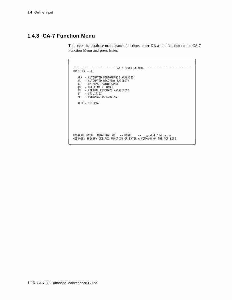
To access the database maintenance functions, enter DB as the function on the CA-7Function Menu and press Enter.
� �
---------------------------- CA-7 FUNCTION MENU ------------------------------
FUNCTION ===>
APA - AUTOMATED PERFORMANCE ANALYSIS
AR - AUTOMATED RECOVERY FACILITY
DB - DATABASE MAINTENANCE
QM - QUEUE MAINTENANCE
RM - VIRTUAL RESOURCE MANAGEMENT
UT - UTILITIES
PS - PERSONAL SCHEDULING
HELP - TUTORIAL
PROGRAM: MNU� MSG-INDX: �� -- MENU -- yy.ddd / hh:mm:ss
MESSAGE: SPECIFY DESIRED FUNCTION OR ENTER A COMMAND ON THE TOP LINE
( )
1-16 CA-7 3.3 Database Maintenance Guide

1.4 Online Input
1.4.4 DB Menu Screen
Use the DB Menu screen to select various database maintenance functions.
� � --------------------- CA-7 DATABASE MAINTENANCE MENU ----------------------
FUNCTION ===>
DATA BASE DEFINITION FOR:
1 - CPU JOB
2 - SCHEDULING
3 - JOB PREDECESSOR/SUCCESSOR
4 - WORKLOAD DOCUMENTATION
5 - INPUT/OUTPUT NETWORK
6 - DATA SET
OTHER FUNCTIONS AVAILABLE:
7 - JCL LIBRARY MAINTENANCE
8 - TEXT EDITOR
9 - CLEAR THE TEXT EDITOR ACTIVE AREA
ACTIVE AREA NOW CONTAINS ���� LINES OF TEXT
PROGRAM: SDM� MSG-INDX: nn -- DB -- yy.ddd / hh:mm:ss
MESSAGE:
( )
To display, enter:
� DBM (or just DB) as a top line command.
� DBM (or just DB) as the FUNCTION value on any other menu or formatted inputscreen.
To exit, enter:
� The name of an online screen as the FUNCTION value or move the cursor to the topline and enter a top line command if some other function is desired.
1.4.4.1 Usage Notes
The desired function is selected by entering its value as the FUNCTION and pressing theEnter key.
Chapter 1. Introduction 1-17
1.4 Online Input
1.4.5 Bypassing the Menu
CA-7 provides extensive menu service for Database Maintenance. The menus are struc-tured to help a novice user step through various screens. However, as proficiencyincreases, it may be desirable to bypass primary menus and proceed directly to thedesired screen.
The primary DB screen may be bypassed by entering a command screen name on the topline of the current screen or as the FUNCTION value on any other menu or formattedscreen. For example, DB.1, DB.4, and so forth.
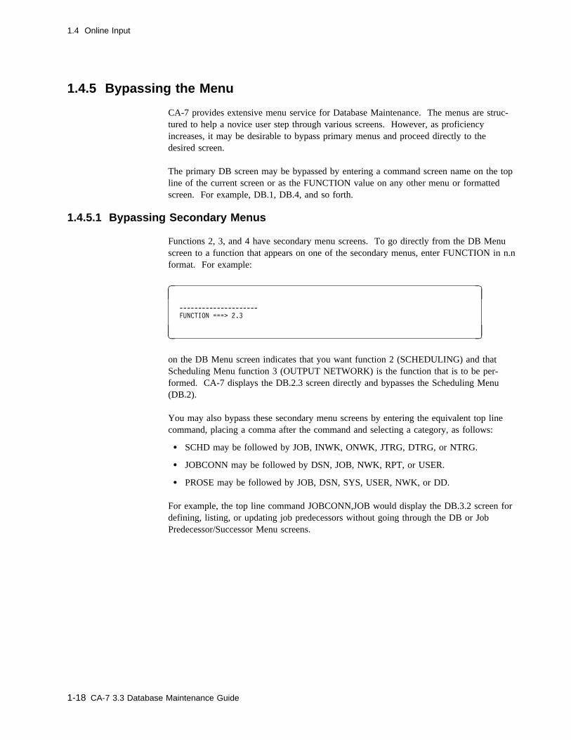
1.4.5.1 Bypassing Secondary Menus
Functions 2, 3, and 4 have secondary menu screens. To go directly from the DB Menuscreen to a function that appears on one of the secondary menus, enter FUNCTION in n.nformat. For example:
� �
---------------------
FUNCTION ===> 2.3
( )
on the DB Menu screen indicates that you want function 2 (SCHEDULING) and thatScheduling Menu function 3 (OUTPUT NETWORK) is the function that is to be per-formed. CA-7 displays the DB.2.3 screen directly and bypasses the Scheduling Menu(DB.2).
You may also bypass these secondary menu screens by entering the equivalent top linecommand, placing a comma after the command and selecting a category, as follows:
� SCHD may be followed by JOB, INWK, ONWK, JTRG, DTRG, or NTRG.
� JOBCONN may be followed by DSN, JOB, NWK, RPT, or USER.
� PROSE may be followed by JOB, DSN, SYS, USER, NWK, or DD.
For example, the top line command JOBCONN,JOB would display the DB.3.2 screen fordefining, listing, or updating job predecessors without going through the DB or JobPredecessor/Successor Menu screens.
1-18 CA-7 3.3 Database Maintenance Guide

1.4 Online Input
1.4.6 Function Shortcuts
An online shortcut for requesting LIST functions of job predecessor/successors andschedule triggers is also available. In this case, keyword values identifying the elementdata desired are included in the top line command following the category, as follows:
� JOBCONN,DSN may be followed by JOB=jobname and SCHID=nnn.
For example:
JOBCONN,DSN,JOB=BACKUP,SCHID=2
lists all DSN connections to job BACKUP for schedule ID 2 with no further inputneeded.
� The SCHD trigger function may be followed by JOB=jobname,DSN=dataset-name/DSNBR=dataset-number or NWK=network-name/DSNBR=network-number (depending on the trigger function).
For example:
SCHD,NTRG,NWK=PAYPUNCH
lists all jobs and schedules triggered by the completion of input networkPAYPUNCH.
1.4.6.1 Shortcut Examples
The following are additional shortcut examples:
JCL,member,JCLID=nnn
Entering this on the top line (where JCLID defaults to zero) has the same result as thefollowing three steps:
1. DB.7 top line command2. FETCH function with member and JCLID of nnn
3. EDIT function
JOB,jobname
Chapter 1. Introduction 1-19

1.4 Online Input
Entering this on the top line has the same result as the following two steps:
1. DB.1 top line command2. LIST function with job name
1.4.7 Function Transfer
To transfer from one menu or formatted screen to another, enter the screen name in theFUNCTION field of the current screen. For example, you may transfer to Queue Mainte-nance by entering QM in the FUNCTION field of the screen.
1.4.8 Aliases for Formatted Screen Functions
All function values for formatted screens may be assigned alternate (alias) names. Thisallows for user-designated abbreviations (for example, L for LIST). It also permits alter-nate values such as CHANGE for UPD. The only restrictions are that the alias namesmust be 8 characters or less, and must not conflict with a function or other alias names.The following is a list of formatted screen function values and some alias names whichare distributed with CA-7:
Function(s) Service level Alias
ADD ADD A,ADDT,AELETE,AIST,APDAPPEND READ AP,APPAPPENDP READ n/aCLEAR n/a CL,CLRDD DELETE n/aDELETE DELETE D,DEL,DELTDELPRRN UPDATE n/aEDIT n/a E,EDITHEXIT n/a n/aFE READ FEIT,FEPL,FEVEFETCH READ FFETCHP READ FPFORMAT n/a FMT,FOR,FORMFPE READ n/aFREE DELETE n/aLIST READ L,LDD,LDIT,LISTA,LISTP,LISTR,LPDRENAME UPDATE RENREPL UPDATE R,REPREQ UPDATE n/aRESOLV SUBMIT RESRET SUBMIT n/aRUN SUBMIT n/aRUNH SUBMIT n/aSAVE ADD SSR UPDATE n/aSS ADD n/aSUBMIT SUBMIT SUB
1-20 CA-7 3.3 Database Maintenance Guide
1.4 Online Input
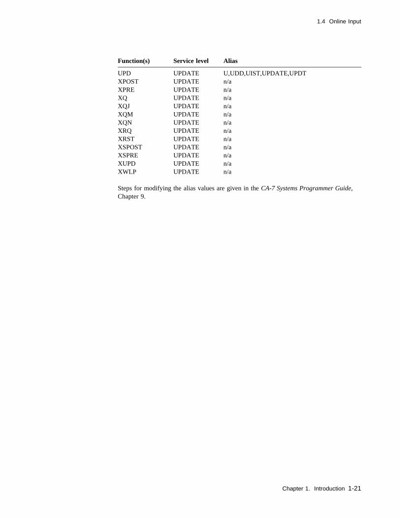
Steps for modifying the alias values are given in the CA-7 Systems Programmer Guide,Chapter 9.
Function(s) Service level Alias
UPD UPDATE U,UDD,UIST,UPDATE,UPDTXPOST UPDATE n/aXPRE UPDATE n/aXQ UPDATE n/aXQJ UPDATE n/aXQM UPDATE n/aXQN UPDATE n/aXRQ UPDATE n/aXRST UPDATE n/aXSPOST UPDATE n/aXSPRE UPDATE n/aXUPD UPDATE n/aXWLP UPDATE n/a
Chapter 1. Introduction 1-21
1.5 Batch Input
1.5 Batch Input
CA-7 supports two different formats for transaction input and output.
The ONLINE format is used in CA-7 online terminal sessions. Online terminal sessionssupport command line input and output as well as data transfer using formatted screens.
Unless the online terminal session is in text editor mode, all input beginning in the upperleft corner of the screen is interpreted as command line input. Transactions entered inthis area are referred to here as command transactions.
A command transaction begins with the command name and may be followed by parame-ters. These transactions are documented in the CA-7 Commands Guide.
Formatted screen transactions differ from command transactions. Input for formattedscreen functions is not solicited at the command line. Formatted screens structure inputand output in an online terminal session using delimited and tagged screen fields. Certainfunctions require formatted screen transactions. Most database maintenance functionsrequire transactions in this mode.
The BATCH format is used by CA-7 external communicators such as the Batch TerminalInterface (BTI) and the CCI Terminal Interface.
Command transactions are entered in batch format just as they would be in an onlineterminal session. However, functions that use formatted screens in the online environ-ment have special syntax requirements in batch, because formatted screens cannot be dis-played in batch.
In those cases where batch and online transaction formats differ, the description of thecorresponding batch transaction format is included in the documentation of each onlinefunction.
See the CA-7 Interfaces Guide for further information on external communicators.
1.5.1 Function Shortcuts and Bypassing the Menu
The shortcuts available online to bypass certain screens are of limited value in batch.Batch transactions should single step from function to function much as a new user wouldstep through a sequence of equivalent screens (for example, DBM, SCHD, JOB, and soforth). Some commands which provide secondary menu screens online, such as DB.2,DB.3 and DB.4, use positional keywords to identify the specific function rather thanrequiring another command to be entered separately.
1-22 CA-7 3.3 Database Maintenance Guide

1.5 Batch Input
1.5.2 Function Transfer
To transfer to another DB function, input a record with the corresponding batch screenname starting in the first column. See the N220 installation job for an example of func-tion transfer between DB mode and top line command mode. To exit from DatabaseMaintenance using batch input, the user must input a record with DBM starting in thefirst column.
1.5.3 Aliases for Formatted Screen Functions
Batch commands may use any of the alias names that were assigned just as they are usedonline. For a list of alias names supplied with CA-7, see 1.4.8, “Aliases for FormattedScreen Functions” on page 1-20.
See the "User Exits and Modifications" chapter of the CA-7 Systems Programmer Guidefor the procedures for assigning alias names.
Chapter 1. Introduction 1-23

1-24 CA-7 3.3 Database Maintenance Guide

Chapter 2. Jobs
This chapter describes setting up and maintaining a job in the CA-7 database.
Chapter 2. Jobs 2-1
2.1 Adding a Job
2.1 Adding a Job
You can add jobs in several ways. The primary method is entering data on the DB.1screen. However, there are other methods.
If the job information already exists in machine-readable form, a program can be writtento perform the DB.1 screen functions using batch commands with a Batch Terminal Inter-face (BTI) job.
For further details on BTI, see the CA-7 Interfaces Guide and 1.5, “Batch Input” onpage 1-22.
If the JCL library has been defined to CA-7 but the jobs have not been added to thedatabase, the user may use the DEMAND command to add the job to the database. Thiscommand causes the job to be executed. The execution includes a LOAD step since thejob is not defined in the database. The LOAD command can also be used to submit thejobs but they do not execute. When scheduled using the LOAD command, the LOADstep executes but the rest of the job's JCL is flushed.
To use the DEMAND or LOAD commands to add the job, certain conditions have to bemet.
1. The job name of the job to be added must be the same as the JCL member name inthe JCL library.
2. Job characteristics must be satisfied by the default values defined for the DB.1screen. The CA-7 default values for the DB.1 screen can be overridden by defininga job named DEFAULTS with the values wanted. System defaults cannot be over-ridden with the DEMAND and LOAD commands. Job characteristics, not coveredby the defaults, must be manually checked.
3. The JCL library ID number or symbolic JCL library name must be specified on thecommand. One JCL library should be given an index value of 0 (zero) so that theDB.1 screen JCLID field does not have to be entered for jobs with JCL residing inthat library when issuing the top line JCL command.
The DEMAND command represents on-request scheduling which is useful on a first-timebasis. As an ongoing practice, it is not recommended except for jobs which must alwaysbe handled as on-request work.
2-2 CA-7 3.3 Database Maintenance Guide
2.2 DB.1 - CPU Job Definition Screen
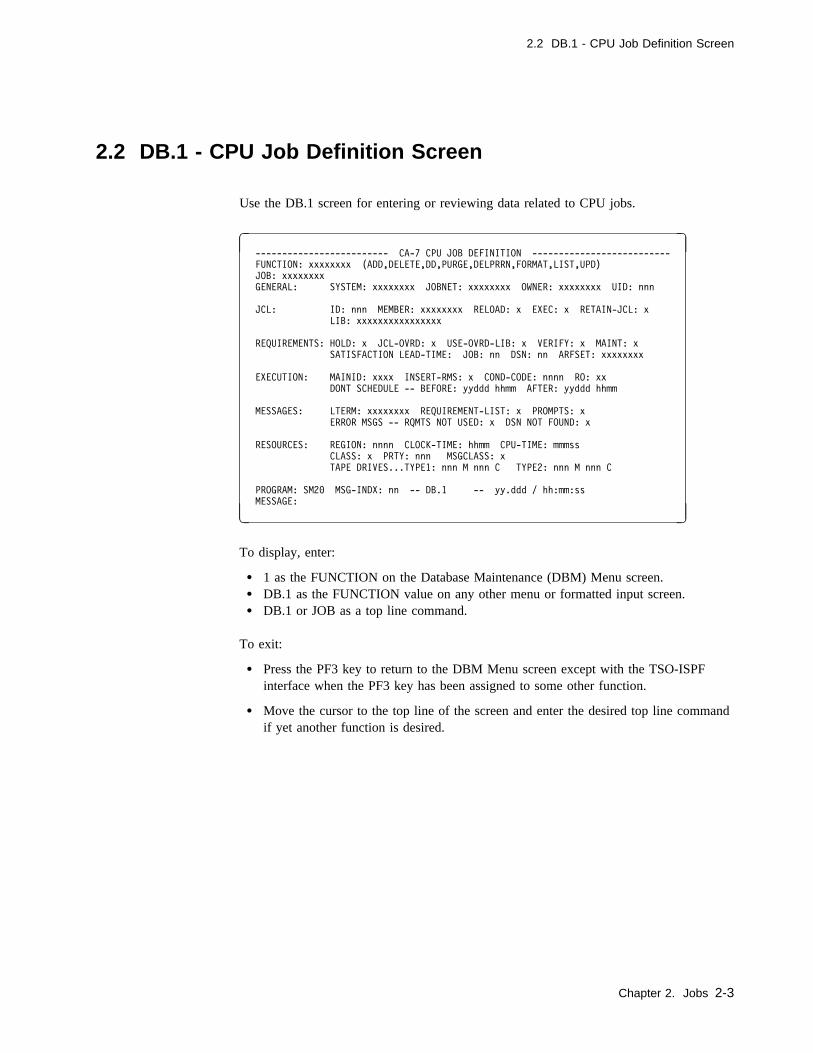
2.2 DB.1 - CPU Job Definition Screen
Use the DB.1 screen for entering or reviewing data related to CPU jobs.
� � ------------------------- CA-7 CPU JOB DEFINITION --------------------------
FUNCTION: xxxxxxxx (ADD,DELETE,DD,PURGE,DELPRRN,FORMAT,LIST,UPD)
JOB: xxxxxxxx
GENERAL: SYSTEM: xxxxxxxx JOBNET: xxxxxxxx OWNER: xxxxxxxx UID: nnn
JCL: ID: nnn MEMBER: xxxxxxxx RELOAD: x EXEC: x RETAIN-JCL: x
LIB: xxxxxxxxxxxxxxxx
REQUIREMENTS: HOLD: x JCL-OVRD: x USE-OVRD-LIB: x VERIFY: x MAINT: x
SATISFACTION LEAD-TIME: JOB: nn DSN: nn ARFSET: xxxxxxxx
EXECUTION: MAINID: xxxx INSERT-RMS: x COND-CODE: nnnn RO: xx
DONT SCHEDULE -- BEFORE: yyddd hhmm AFTER: yyddd hhmm
MESSAGES: LTERM: xxxxxxxx REQUIREMENT-LIST: x PROMPTS: x
ERROR MSGS -- RQMTS NOT USED: x DSN NOT FOUND: x
RESOURCES: REGION: nnnn CLOCK-TIME: hhmm CPU-TIME: mmmss
CLASS: x PRTY: nnn MSGCLASS: x
TAPE DRIVES...TYPE1: nnn M nnn C TYPE2: nnn M nnn C
PROGRAM: SM2� MSG-INDX: nn -- DB.1 -- yy.ddd / hh:mm:ss
MESSAGE:
( )
To display, enter:
� 1 as the FUNCTION on the Database Maintenance (DBM) Menu screen.� DB.1 as the FUNCTION value on any other menu or formatted input screen.� DB.1 or JOB as a top line command.
To exit:
� Press the PF3 key to return to the DBM Menu screen except with the TSO-ISPFinterface when the PF3 key has been assigned to some other function.
� Move the cursor to the top line of the screen and enter the desired top line commandif yet another function is desired.
Chapter 2. Jobs 2-3
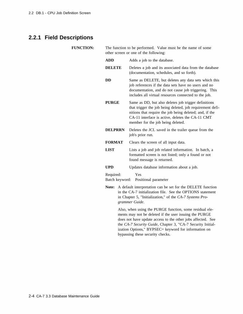
2.2 DB.1 - CPU Job Definition Screen
2.2.1 Field Descriptions
FUNCTION: The function to be performed. Value must be the name of someother screen or one of the following:
ADD Adds a job to the database.
DELETE Deletes a job and its associated data from the database(documentation, schedules, and so forth).
DD Same as DELETE, but deletes any data sets which thisjob references if the data sets have no users and nodocumentation, and do not cause job triggering. Thisincludes all virtual resources connected to the job.
PURGE Same as DD, but also deletes job trigger definitionsthat trigger the job being deleted, job requirement defi-nitions that require the job being deleted; and, if theCA-11 interface is active, deletes the CA-11 CMTmember for the job being deleted.
DELPRRN Deletes the JCL saved in the trailer queue from thejob's prior run.
FORMAT Clears the screen of all input data.
LIST Lists a job and job related information. In batch, aformatted screen is not listed; only a found or notfound message is returned.
UPD Updates database information about a job.
Required: YesBatch keyword: Positional parameter
Note: A default interpretation can be set for the DELETE functionin the CA-7 initialization file. See the OPTIONS statementin Chapter 5, "Initialization," of the CA-7 Systems Pro-grammer Guide.
Also, when using the PURGE function, some residual ele-ments may not be deleted if the user issuing the PURGEdoes not have update access to the other jobs affected. Seethe CA-7 Security Guide, Chapter 3, "CA-7 Security Initial-ization Options," BYPSEC= keyword for information onbypassing these security checks.
2-4 CA-7 3.3 Database Maintenance Guide
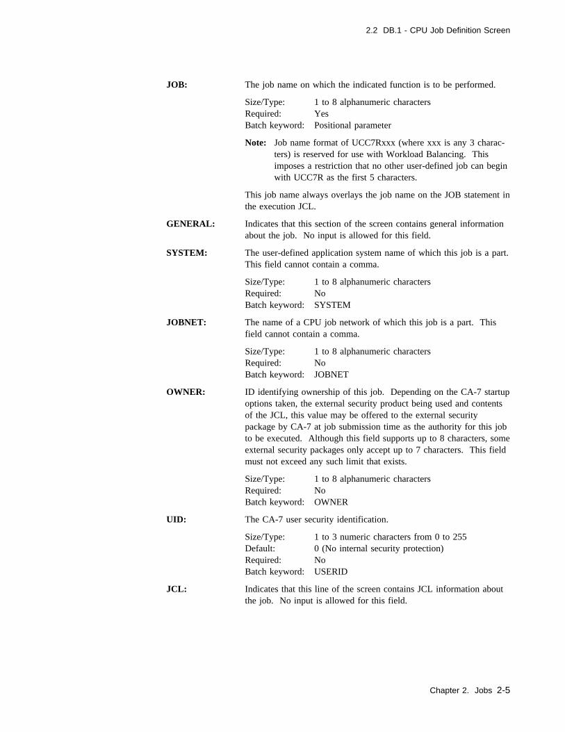
2.2 DB.1 - CPU Job Definition Screen
JOB: The job name on which the indicated function is to be performed.
Size/Type: 1 to 8 alphanumeric charactersRequired: YesBatch keyword: Positional parameter
Note: Job name format of UCC7Rxxx (where xxx is any 3 charac-ters) is reserved for use with Workload Balancing. Thisimposes a restriction that no other user-defined job can beginwith UCC7R as the first 5 characters.
This job name always overlays the job name on the JOB statement inthe execution JCL.
GENERAL: Indicates that this section of the screen contains general informationabout the job. No input is allowed for this field.
SYSTEM: The user-defined application system name of which this job is a part.This field cannot contain a comma.
Size/Type: 1 to 8 alphanumeric charactersRequired: NoBatch keyword: SYSTEM
JOBNET: The name of a CPU job network of which this job is a part. Thisfield cannot contain a comma.
Size/Type: 1 to 8 alphanumeric charactersRequired: NoBatch keyword: JOBNET
OWNER: ID identifying ownership of this job. Depending on the CA-7 startupoptions taken, the external security product being used and contentsof the JCL, this value may be offered to the external securitypackage by CA-7 at job submission time as the authority for this jobto be executed. Although this field supports up to 8 characters, someexternal security packages only accept up to 7 characters. This fieldmust not exceed any such limit that exists.
Size/Type: 1 to 8 alphanumeric charactersRequired: NoBatch keyword: OWNER
UID: The CA-7 user security identification.
Size/Type: 1 to 3 numeric characters from 0 to 255Default: 0 (No internal security protection)Required: NoBatch keyword: USERID
JCL: Indicates that this line of the screen contains JCL information aboutthe job. No input is allowed for this field.
Chapter 2. Jobs 2-5

2.2 DB.1 - CPU Job Definition Screen
ID: A numeric index value associated with a JCL library. Two valueshave special significance: 254 is reserved to indicate the overridelibrary (see USE-OVRD-LIB field for additional information) and255 is reserved for use with the HELP library. 255 is also assignedto libraries that are referenced using a symbolic index (see LIB fieldfor additional information). LIB and ID are mutually exclusive.
Size/Type: 1 to 3 numeric characters from 0 to 253Default: 0Required: NoBatch keyword: JCLID
MEMBER: The JCL library member name.
Size/Type: 1 to 8 alphanumeric charactersDefault: Job nameRequired: No (required if member name and job name are
different)Batch keyword: JCLMBR
RELOAD: Indicates if this job's JCL is to be reloaded (Y, N, or X). When ajob comes into the request queue, it is either flagged for load proc-essing or not flagged. If RELOAD=X, then the job is not flaggedfor load processing unless the LOAD command is used. IfRELOAD=Y, then the job is flagged for load processing. IfRELOAD=N, then the job is not flagged for load processing unless itis the first time it has run in CA-7. A RELOAD=Y is automaticallyreset to N once the load completes successfully. A RELOAD=X isnever automatically changed even if the LOAD command is used.
Default: NRequired: NoBatch keyword: RELOAD
EXEC: Indicates whether this job should be executed (Y or N). If N isused, the job does not run but shows a normal completion as if it didrun. JCL is not required for nonexecutable jobs. VRM definitionsfor the job are ignored if EXEC of N is used.
Note: ARF recovery will not be invoked for non-executable jobs.
Default: YRequired: NoBatch keyword: EXEC
RETAIN-JCL: Indicates whether execution JCL is to be retained in the trailer queueafter a successful run (Y or N).
Default: NRequired: NoBatch keyword: RETJCL
2-6 CA-7 3.3 Database Maintenance Guide

2.2 DB.1 - CPU Job Definition Screen
LIB: JCL library identification. Must be a symbolic INDEX assigned to aJCL statement. Symbolic value &HELP is reserved for the HELPlibrary. LIB and ID are mutually exclusive.
Size/Type: 2 to 16 alphanumeric characters beginning withampersand (&)
Required: NoBatch keyword: JCLLIB
Note: Schedule scan uses the current specification for LIB whenattempting to attach the JCL for a job in the request queuewith RETRY status.
REQUIREMENTS:Indicates that this section of the screen contains requirements infor-mation about the job. No input is allowed for this field.
HOLD: Indicates whether this job is to be placed in a hold status when itenters the request queue (Y or N).
Default: NRequired: NoBatch keyword: HOLD
JCL-OVRD: Indicates whether this job needs manual JCL overrides before it canbe submitted (Y or N). Similar to the JCLOVRD command.
Default: NRequired: NoBatch keyword: JCLOVR
USE-OVRD-LIB: Indicates whether the JCL is to be retrieved from the JCL Overridelibrary (JCLID=254) for the next run only (Y or N). This field isautomatically set back to N the next time the job comes into therequest queue.
Default: NRequired: NoBatch keyword: JOVRDLIB
VERIFY: Indicates whether this job requires any presubmission manual verifi-cation (Y or N). Similar to VERIFY command.
Default: NRequired: NoBatch keyword: VERIFY
Chapter 2. Jobs 2-7

2.2 DB.1 - CPU Job Definition Screen
MAINT: Indicates whether this job is a maintenance job (for example, asystem utility) with no production data set requirements (Y or N). IfMAINT=Y, then all input data set requirements are ignored. Noneof the output data sets created by this job are posted back to CA-7.
Marking a job as MAINT allows job triggering but not data set trig-gering.
In addition, if the LOADDSNS keyword is used on the DBASEstatement in the initialization file, then the LOAD process does notbuild any DD or data set information for jobs that are markedMAINT=Y on the DB.1 (JOB) screen. This means that there willnot be any data set connections for these jobs unless added manually.
Default: NRequired: NoBatch keyword: MAINT
SATISFACTION LEAD-TIME:Indicates that this area of the screen contains lead time informationabout the job requirements. No input is allowed for this field.
JOB: The number of hours to be considered when satisfying job dependentrequirements. Values are:
Default: 0Batch keyword: JOBLDTM
0 Indicates no lead time is to be considered when satisfying thisjob's requirements.
99 The requirement is never to be considered as already satisfiedwhen the job enters the queues. Each predecessor job mustcomplete normally while this job is in the request queue.
nn Since the last run of this job, each predecessor job must haverun within the last nn hours. Values for nn may be from 1 to98.
Note: JOB and DSN are on a global level for all job and data setrequirements which have a LEADTM value of 0000 on theDB.3 screens. This applies to all SCHIDs that the job runsunder. See 4.3.1, “DB.3 - Job Predecessor/Successor MenuScreen” on page 4-6.
DSN: The number of hours to be considered when satisfying data setrequirements. For a description of values, see preceding field name(JOB).
Size/Type: 1 to 2 numeric characters from 0-99Default: 0 (indicates ignore this field)Required: NoBatch keyword: DSNLDTM
2-8 CA-7 3.3 Database Maintenance Guide
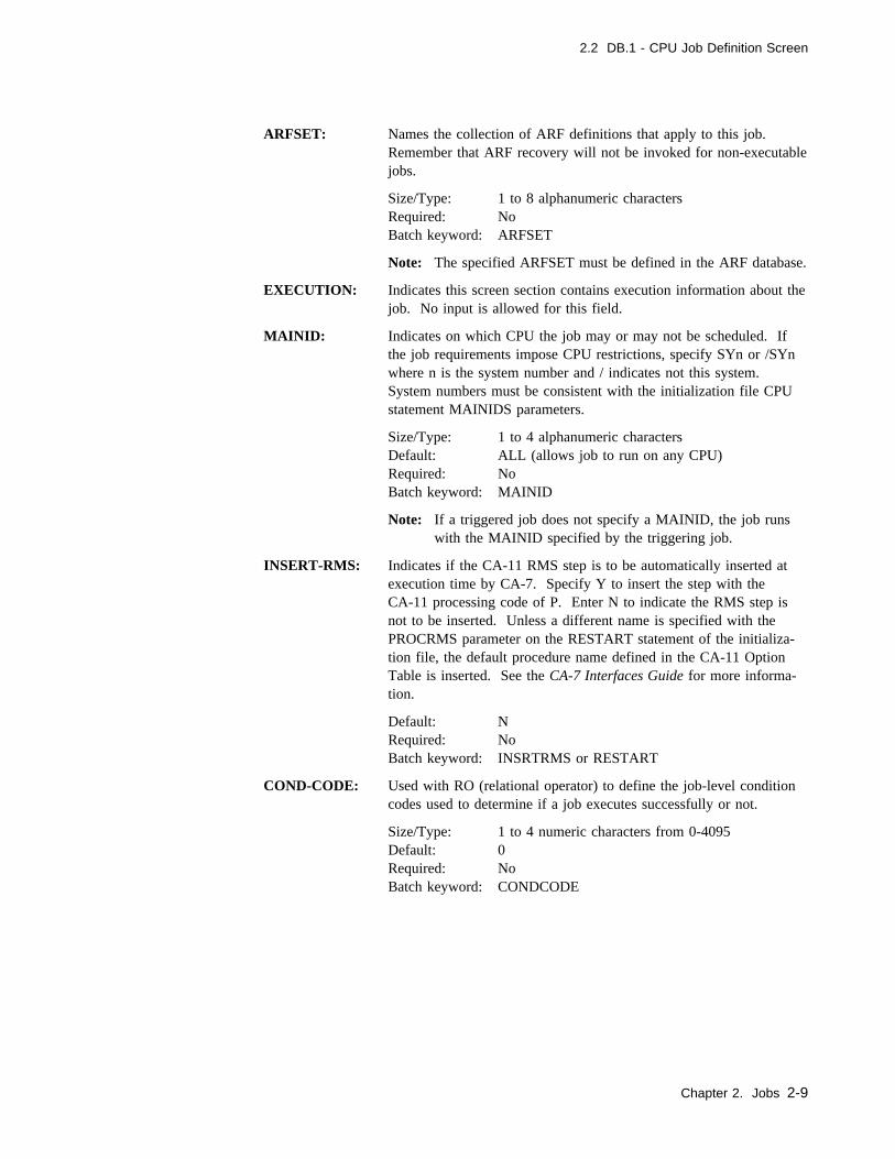
2.2 DB.1 - CPU Job Definition Screen
ARFSET: Names the collection of ARF definitions that apply to this job.Remember that ARF recovery will not be invoked for non-executablejobs.
Size/Type: 1 to 8 alphanumeric charactersRequired: NoBatch keyword: ARFSET
Note: The specified ARFSET must be defined in the ARF database.
EXECUTION: Indicates this screen section contains execution information about thejob. No input is allowed for this field.
MAINID: Indicates on which CPU the job may or may not be scheduled. Ifthe job requirements impose CPU restrictions, specify SYn or /SYnwhere n is the system number and / indicates not this system.System numbers must be consistent with the initialization file CPUstatement MAINIDS parameters.
Size/Type: 1 to 4 alphanumeric charactersDefault: ALL (allows job to run on any CPU)Required: NoBatch keyword: MAINID
Note: If a triggered job does not specify a MAINID, the job runswith the MAINID specified by the triggering job.
INSERT-RMS: Indicates if the CA-11 RMS step is to be automatically inserted atexecution time by CA-7. Specify Y to insert the step with theCA-11 processing code of P. Enter N to indicate the RMS step isnot to be inserted. Unless a different name is specified with thePROCRMS parameter on the RESTART statement of the initializa-tion file, the default procedure name defined in the CA-11 OptionTable is inserted. See the CA-7 Interfaces Guide for more informa-tion.
Default: NRequired: NoBatch keyword: INSRTRMS or RESTART
COND-CODE: Used with RO (relational operator) to define the job-level conditioncodes used to determine if a job executes successfully or not.
Size/Type: 1 to 4 numeric characters from 0-4095Default: 0Required: NoBatch keyword: CONDCODE
Chapter 2. Jobs 2-9

2.2 DB.1 - CPU Job Definition Screen
RO: Indicates the relational operator of the condition code(COND-CODE) or if the step level #SCC statements are being usedin the job's JCL. Values are:
EQ Equal to
LT Less than
GT Greater than
GE Greater than or equal to
LE Less than or equal to
NE Not equal to
#S Step condition code tests to be made based on #SCC statementsin the JCL. See 10.3.4, “#SCC Statement” on page 10-18 forthe use of the #SCC statement.
IG No evaluation of the job is done. CA-7 always assumes the jobcompletes successfully, regardless of condition codes, abendcodes, or run-time JCL errors. When this is used, theINSERT-RMS fields should be N.
0 No condition test is to be made.
Default: 0Required: NoBatch keyword: RELOPR
If 0 is used, no test is made on the job's condition code.
The highest condition code that this job generates is tested by thispair of parameters. For example, if COND-CODE is set at 8 andRO is set at LT, the job is marked as completing abnormally if 8 isless than the job's highest condition code.
Note: This test is for CA-7's internal use only. It simply tells CA-7what action to take after the job completes. CA-7 does notdetermine or control which steps are to be executed.
2-10 CA-7 3.3 Database Maintenance Guide
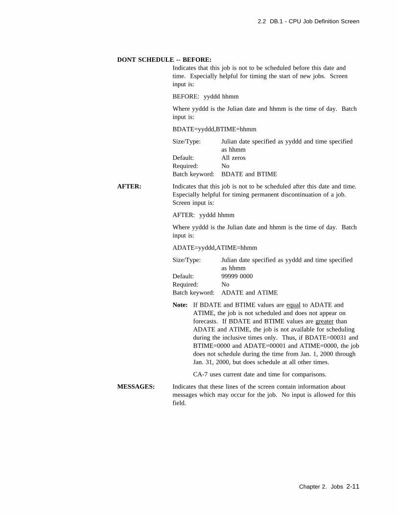
2.2 DB.1 - CPU Job Definition Screen
DONT SCHEDULE -- BEFORE:Indicates that this job is not to be scheduled before this date andtime. Especially helpful for timing the start of new jobs. Screeninput is:
BEFORE: yyddd hhmm
Where yyddd is the Julian date and hhmm is the time of day. Batchinput is:
BDATE=yyddd,BTIME=hhmm
Size/Type: Julian date specified as yyddd and time specifiedas hhmm
Default: All zerosRequired: NoBatch keyword: BDATE and BTIME
AFTER: Indicates that this job is not to be scheduled after this date and time.Especially helpful for timing permanent discontinuation of a job.Screen input is:
AFTER: yyddd hhmm
Where yyddd is the Julian date and hhmm is the time of day. Batchinput is:
ADATE=yyddd,ATIME=hhmm
Size/Type: Julian date specified as yyddd and time specifiedas hhmm
Default: 99999 0000Required: NoBatch keyword: ADATE and ATIME
Note: If BDATE and BTIME values are equal to ADATE andATIME, the job is not scheduled and does not appear onforecasts. If BDATE and BTIME values are greater thanADATE and ATIME, the job is not available for schedulingduring the inclusive times only. Thus, if BDATE=00031 andBTIME=0000 and ADATE=00001 and ATIME=0000, the jobdoes not schedule during the time from Jan. 1, 2000 throughJan. 31, 2000, but does schedule at all other times.
CA-7 uses current date and time for comparisons.
MESSAGES: Indicates that these lines of the screen contain information aboutmessages which may occur for the job. No input is allowed for thisfield.
Chapter 2. Jobs 2-11

2.2 DB.1 - CPU Job Definition Screen
LTERM: Messages about this job are to be routed to this logical terminalname.
Size/Type: 1 to 8 alphanumeric charactersDefault: If not entered, the LTERM associated with the JCL
library in the initialization file JCL statement isused. If LTERM is not specified on the JCL state-ment, the default is MASTER.
Required: NoBatch keyword: LTERM
REQUIREMENT - LIST:Indicates whether preexecution requirements are to be listed for thisjob when it enters the request queue (Y or N).
Default: YRequired: NoBatch keyword: RQLST
PROMPTS: Indicates if prompt messages are to be issued if this job is late (Y orN).
Default: YRequired: NoBatch keyword: PROMPT
Note: If LATEPROMPT=LATE is specified on the OPTIONSstatement of the CA-7 initialization file, setting this value tono (N) will prevent the job from ever having a status ofLATE on an LQ or LRLOG display. Jobs defined with avalue of yes (Y) will be processed the same regardless of theLATEPROMPT setting.
ERROR MSGS -- RQMTS NOT USED:Indicates whether error messages for job requirements not used are tobe issued (Y or N).
Default: YRequired: NoBatch keyword: RQMSG
DSN NOT FOUND:Indicates whether error messages for data sets used at execution timebut not found in the CA-7 database are to be listed (Y or N).
Default: Y (The messages are not issued if PERFORM=1 isspecified on the INIT statement in the initializationfile.)
Required: NoBatch keyword: DSNMSG
RESOURCES: These lines contain resource information about the job. No input isallowed in this field.
2-12 CA-7 3.3 Database Maintenance Guide

2.2 DB.1 - CPU Job Definition Screen
REGION: The region size required by this job. For information only.
Size/Type: 1 to 4 numeric charactersDefault: 0Required: NoBatch keyword: REGION
CLOCK-TIME: CA-7 maintains certain SMF feedback data in its database, includinga weighted average elapsed runtime. If the database is updated witha time of 0000, the counters for number of runs, number of timeslate, and number of restarts are also reset to 0000. One use of thisvalue is deadline prompting. If 2359 is specified, deadline prompttime is not adjusted. It remains due-out time minus lead time.
Note: Clock time and CPU time averages are not updated if the jobeither fails (abend, JCL error, and so on) or is restarted. Theweighted average is the value in the database times 5, plusthe value from the current run, divided by 6. This tends tokeep the current run from possibly skewing the value.
Size/Type: 4 numeric characters specified as hhmm, where hhcan be 00 through 23 and mm can be from 00 to59
Default: 0000Required: NoBatch keyword: ELAPTM
CPU-TIME: CA-7 maintains weighted average CPU time usage values for eachjob in its database. (See the preceding note under CLOCK-TIME.)
Size/Type: 5 numeric characters specified as mmmss, wheremmm is minutes and ss is seconds
Batch keyword: CPUTM
CLASS: Indicates the CA-7 WLB job class. If using Workload Balancing,any job without a specified job class is automatically assigned toclass A. Also, for workload balancing, any job that enters the queueas a result of a RUN(H) command is assigned to class 9. Any jobthat enters the queue as a result of a LOAD(H) command is assignedto class 8. Does not have to match the JOB statement CLASS value.
Size/Type: 1 alphanumeric characterDefault: A spaceRequired: NoBatch keyword: CLASS
Chapter 2. Jobs 2-13
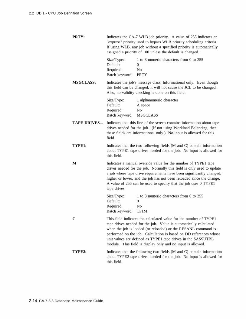
2.2 DB.1 - CPU Job Definition Screen
PRTY: Indicates the CA-7 WLB job priority. A value of 255 indicates an"express" priority used to bypass WLB priority scheduling criteria.If using WLB, any job without a specified priority is automaticallyassigned a priority of 100 unless the default is changed.
Size/Type: 1 to 3 numeric characters from 0 to 255Default: 0Required: NoBatch keyword: PRTY
MSGCLASS: Indicates the job's message class. Informational only. Even thoughthis field can be changed, it will not cause the JCL to be changed.Also, no validity checking is done on this field.
Size/Type: 1 alphanumeric characterDefault: A spaceRequired: NoBatch keyword: MSGCLASS
TAPE DRIVES... Indicates that this line of the screen contains information about tapedrives needed for the job. (If not using Workload Balancing, thenthese fields are informational only.) No input is allowed for thisfield.
TYPE1: Indicates that the two following fields (M and C) contain informationabout TYPE1 tape drives needed for the job. No input is allowed forthis field.
M Indicates a manual override value for the number of TYPE1 tapedrives needed for the job. Normally this field is only used to updatea job where tape drive requirements have been significantly changed,higher or lower, and the job has not been reloaded since the change.A value of 255 can be used to specify that the job uses 0 TYPE1tape drives.
Size/Type: 1 to 3 numeric characters from 0 to 255Default: 0Required: NoBatch keyword: TP1M
C This field indicates the calculated value for the number of TYPE1tape drives needed for the job. Value is automatically calculatedwhen the job is loaded (or reloaded) or the RESANL command isperformed on the job. Calculation is based on DD references whoseunit values are defined as TYPE1 tape drives in the SASSUTBLmodule. This field is display only and no input is allowed.
TYPE2: Indicates that the following two fields (M and C) contain informationabout TYPE2 tape drives needed for the job. No input is allowed forthis field.
2-14 CA-7 3.3 Database Maintenance Guide
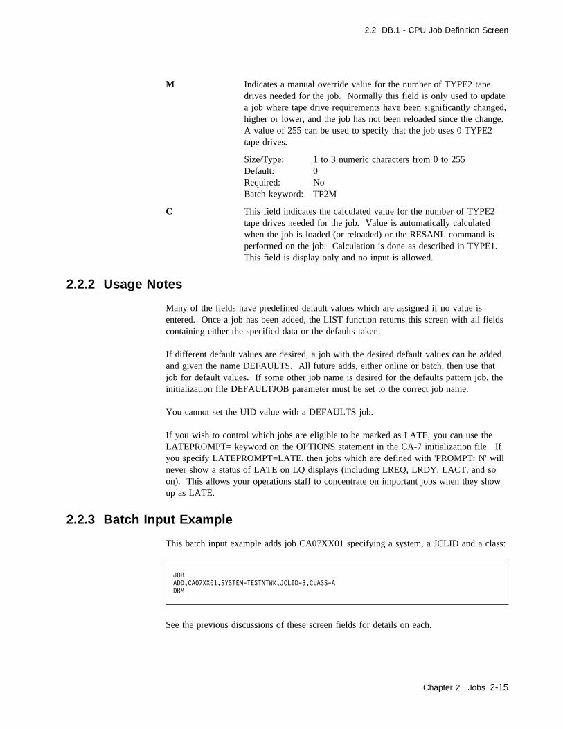
2.2 DB.1 - CPU Job Definition Screen
M Indicates a manual override value for the number of TYPE2 tapedrives needed for the job. Normally this field is only used to updatea job where tape drive requirements have been significantly changed,higher or lower, and the job has not been reloaded since the change.A value of 255 can be used to specify that the job uses 0 TYPE2tape drives.
Size/Type: 1 to 3 numeric characters from 0 to 255Default: 0Required: NoBatch keyword: TP2M
C This field indicates the calculated value for the number of TYPE2tape drives needed for the job. Value is automatically calculatedwhen the job is loaded (or reloaded) or the RESANL command isperformed on the job. Calculation is done as described in TYPE1.This field is display only and no input is allowed.
2.2.2 Usage Notes
Many of the fields have predefined default values which are assigned if no value isentered. Once a job has been added, the LIST function returns this screen with all fieldscontaining either the specified data or the defaults taken.
If different default values are desired, a job with the desired default values can be addedand given the name DEFAULTS. All future adds, either online or batch, then use thatjob for default values. If some other job name is desired for the defaults pattern job, theinitialization file DEFAULTJOB parameter must be set to the correct job name.
You cannot set the UID value with a DEFAULTS job.
If you wish to control which jobs are eligible to be marked as LATE, you can use theLATEPROMPT= keyword on the OPTIONS statement in the CA-7 initialization file. Ifyou specify LATEPROMPT=LATE, then jobs which are defined with 'PROMPT: N' willnever show a status of LATE on LQ displays (including LREQ, LRDY, LACT, and soon). This allows your operations staff to concentrate on important jobs when they showup as LATE.
2.2.3 Batch Input Example
This batch input example adds job CA07XX01 specifying a system, a JCLID and a class:
JOB
ADD,CA�7XX�1,SYSTEM=TESTNTWK,JCLID=3,CLASS=A
DBM
See the previous discussions of these screen fields for details on each.
Chapter 2. Jobs 2-15

2.3 Changing a Job
2.3 Changing a Job
The basic way to change a job's characteristics, which appear on the DB.1 screen, is touse the UPD function. However, you can make wholesale changes to many jobs usingthe Batch Terminal Interface (BTI) facility. For further details on BTI, see the CA-7Interfaces Guide and 1.5, “Batch Input” on page 1-22. Refer also to the Database Trans-portability chapter of this guide for a discussion of another tool that can be very helpfulwhen making extensive changes.
The database information should always agree with the JCL for the job. Therefore,whenever permanent changes are made to the JCL, you should resynchronize the databasewith new JCL. The CA-7 LOAD process accomplishes this, and you can handle it in oneof several ways.
� Manually issue a LOAD command after the JCL has been changed.
� Set the RELOAD value on the DB.1 screen to Y if the change is made outside ofCA-7 (for example, through TSO).
� Make any permanent changes to the JCL through the DB.7 screen. This causes theRELOAD field on the DB.1 screen to be set to Y automatically.
Note: The DB.3 screens establish dependency relationships for CPU jobs, workstationnetworks, and so forth, thereby defining prerequisites. Whenever the JCL changesfor any job, the user must consider whether those changes affect the dependencyrelationships for the job. See 4.3.1, “DB.3 - Job Predecessor/Successor MenuScreen” on page 4-6.
2-16 CA-7 3.3 Database Maintenance Guide
Chapter 3. Scheduling
This chapter identifies the screens and commands used to schedule work in CA-7.
Chapter 3. Scheduling 3-1
3.1 Work Scheduling
3.1 Work Scheduling
CA-7 uses both date/time-driven and event-driven facilities to cause work to be scheduledand initiated. To CA-7, work is defined as CPU jobs and/or preprocessing andpostprocessing workstation networks. Event-driven scheduling, known as trigger sched-uling, is a far more efficient technique than date/time oriented schedules. See 3.1.3,“Event Scheduling” on page 3-6 for more details on this technique.
For CPU jobs and preprocessing networks, date/time-driven schedules are generatedthrough definition of base calendars and definition of schedules relative to base calendars.Once defined, work is automatically scheduled based on defined schedules and currentdate and time values within the CA-7 system. For postprocessing networks, output work-stations are scheduled based on the scheduling of the CPU job to which the networks areconnected.
Event-driven scheduling causes jobs to be scheduled or initiated based on completion of aprevious activity or event. Event mechanisms are the creation of required data sets, com-pletion of predecessor jobs, or completion of a preprocessing network.
Time-driven and event-driven facilities may be used in combination when scheduling andinitiating work. For example, a CPU job may have a timed schedule for processing butmay also have dependencies on data sets created by another job. When combined, timeand event requirements must be satisfied before work is initiated.
The user should be aware that the schedule ID offers a powerful scheduling tool.Requirements, networks, JCL overrides, job triggers, and so forth, can all be variedthrough the use of different schedule IDs. For example, if a given job is to run onMonday through Friday but the requirements vary on Fridays, this same job could have adifferent schedule ID defined for its Friday run.
Multiple schedule options may be chosen for a single schedule ID (for example, daily andmonthly). However, a job which is scheduled automatically on a defined date/time basisis not scheduled more than once per day for a given schedule ID.
3-2 CA-7 3.3 Database Maintenance Guide
3.1 Work Scheduling
3.1.1 Date and Time Scheduling
Date/time-driven scheduling is performed by the schedule scan function of CA-7 based oninitialization file parameters and database definitions. By combining base calendar andschedule definitions through a resolution process, CA-7 stores information about date/timerelated work in its database.
3.1.1.1 Base Calendars
Base calendars define available processing days for the installation. Any number of basecalendars may be defined. However, it may be possible to satisfy installation require-ments with only one or two calendars.
Each calendar defines a single year comprised of twelve months with a starting and year-ending boundary that can be crossed only in the first or twelfth month. A given calendarmay represent schedule months in either standard or user-defined format (for example,accounting, fiscal, and so forth).
Base calendars can be generated through either batch or online facilities. To use theonline facility (DB.2.8), a CA-7 calendar PDS must be allocated and identified to CA-7.See the CA-7 Systems Programmer Guide for information on enabling online calendarmaintenance. Processing of base calendars for resolution of schedules is the same regard-less of whether they were generated using the batch or online facilities.
Calendars can be generated through the CA-7 CALENDAR macro. Macro keywords areused for calendar definition and the macro is assembled and link edited using standardprocedures. Base calendars are link edited to the CA-7 LOADLIB or a specified calendarlibrary, and are stored in the form of bit masks which represent available and unavailableprocessing days for the year.
Timing for generation of base calendars is flexible. The only requirement is that a partic-ular calendar exist before resolution of work schedules related to the calendar isattempted. Base calendars must be regenerated whenever available processing dayschange and before the beginning of each year. Generally, next year's base calendar(s)should be generated by July 1 of the current year. New base calendars may be generatedat any time without impacting current processing schedules. Schedule resolution,described later, is used to change the processing schedules, for jobs or networks, with anew year or changed base calendars.
PRINT Command:
Use the PRINT command to produce a month-by-month listing of indicated base calen-dars. PRINT produces output which reflects the beginning and ending days of eachmonth, holidays, or any other nonprocessing days that were defined when the calendarwas produced. The PRINT command is described in the CA-7 Commands Guide.
Chapter 3. Scheduling 3-3

3.1 Work Scheduling
3.1.1.2 Schedule Definition
Definition of work schedules is accomplished through DB.2 screens. This processinvolves identifying when work is to be processed in relation to given calendars. When aschedule is initially defined (or changed), schedule resolution with the base calendar(s) isused to complete the definition of the processing schedule.
3.1.1.3 Schedule Resolution
Once calendars and schedules are defined, schedules are resolved against calendars toensure compatibility and create the processing schedule. This is accomplished throughthe RESOLV facility which is available as both a top line command and a function onthe DB.2 screens. The result of this resolution is the schedule used by CA-7 to schedulepreprocessing work and jobs. Figure 3-1 on page 3-5 illustrates this function. Thefigure demonstrates the path for a base calendar generated through the batch facility.Calendars generated through the online base calendar maintenance facility (DB.2.8) take adifferent path leading up to the resolution phase but are treated the same as batch calen-dars in the actual resolution of schedules.
RESOLV Command:
Use the top line RESOLV command to create or modify processing schedules for jobs orworkstation networks which are to be scheduled on a date/time basis. Work which isscheduled by a trigger or on-request work which is DEMANDed or RUN has no directrelationship to a base calendar and therefore does not require the use of this function.
Whenever a calendar-oriented processing schedule expires (at the end of June or the endof the year) or the scheduling frequency is redefined for any other reason, it againbecomes necessary to resolve the schedule. Options on the RESOLV command are pro-vided for resolving all or any subset of those tasks scheduled with a single command.The RESOLV command is fully described in the CA-7 Commands Guide.
3-4 CA-7 3.3 Database Maintenance Guide
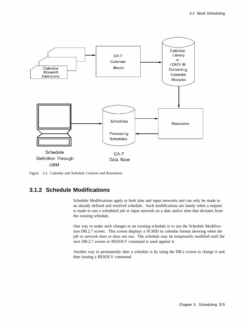
3.1 Work Scheduling
Figure 3-1. Calendar and Schedule Creation and Resolution
3.1.2 Schedule Modifications
Schedule Modifications apply to both jobs and input networks and can only be made toan already defined and resolved schedule. Such modifications are handy when a requestis made to run a scheduled job or input network on a date and/or time that deviates fromthe existing schedule.
One way to make such changes to an existing schedule is to use the Schedule Modifica-tion DB.2.7 screen. This screen displays a SCHID in calendar format showing when thejob or network does or does not run. The schedule may be temporarily modified until thenext DB.2.7 screen or RESOLV command is used against it.
Another way to permanently alter a schedule is by using the DB.2 screen to change it andthen issuing a RESOLV command.
Chapter 3. Scheduling 3-5

3.1 Work Scheduling
3.1.2.1 Schedule Scan
Schedule scan causes scheduled work to be automatically brought into the system. Basedon time intervals specified in the SCHEDULE statement in the initialization file, schedulescan is activated and loads work into the system which is to start within the specifiedinterval. After a system down condition, schedule scan normally continues where it leftoff; however, under unusual conditions it may be set back to a specific time to allow foreasier recovery.
3.1.3 Event Scheduling
3.1.3.1 Triggers
Schedule triggers can be used as a more efficient alternative to date/time schedules. Trig-gers cause jobs to be dynamically scheduled based solely on completion of an event. Thetriggering event may be date/time scheduled or it too can be automatically triggered byeven another event. Schedule triggers have no association with a calendar. Therefore, nocalendar related maintenance is ever required. Once defined, triggers are perpetual,remaining in effect until they are either deleted or modified by the user. In addition torelieving the user of annual calendar schedule maintenance, triggers are a far more effi-cient scheduling mechanism in terms of system overhead. There are three types of trig-gers available in CA-7:
� Job � Network � Data Set
With each trigger, multiple jobs can be triggered if so desired.
Job Triggers: When a predecessor job completes successfully, a trigger initiates sched-uling of the successor or dependent job(s) that will be brought into the request queue.This newly triggered job may also have a trigger definition that, upon successful com-pletion, causes another job to start. For ease of definition and understanding, thepredecessor/successor relationship is commonly used to control sequencing of jobs in theproduction environment. Job triggers are defined with the DB.2.4 function.
Network Triggers: Input (or preprocessing) workstation networks can be used totrigger CPU jobs which are dependent on the completion of that network. These triggerstake effect whenever the last workstation in the network is posted as being complete.The job(s) to be triggered is defined through the DB.2.5 function.
Multiple jobs can be triggered by the completion of a single network. Output (orpostprocessing) networks cannot be used to trigger jobs.
Data Set Triggers: Data set output activity can also be used as a trigger. Whenever asequential data set is created or updated, CPU jobs can be triggered by the completion ofthat activity. Scheduling of jobs in this manner is accomplished through the DB.2.6 andDB.6 screens.
3-6 CA-7 3.3 Database Maintenance Guide
3.1 Work Scheduling
A data set cannot be used as a trigger if it is defined as PERM=YES on the DB.6 screenor if it is output by a job which is defined as MAINT=YES.
Data set triggers are very useful if you have a job which needs to run only if a specificdata set has been created.
If the data set used as a trigger specifies YES for the DB.6 screen parameter POST ATCLOSE TIME, the data set trigger takes effect when the data set is successfully closedafter being opened for output or update. If POST AT CLOSE TIME is NO, then thetrigger takes effect on successful completion of the job in which the data set was createdor updated.
The advantage of posting at close time is that successful completion of an entire job isnot necessary for data set triggering or requirement posting to take place.
Note: If you trigger a job at data set close, the trigger occurs then, even if the job thatcreated the data set later abends. If the abended job is then restarted and the dataset is re-created, the trigger occurs again.
3.1.4 On-Request Scheduling
Provisions are included in CA-7 to permit on-request scheduling of work. This is themethod of scheduling jobs which do not have predefined processing cycles (or jobs thatmust be forced into early execution). However, on-request scheduling, using the RUNcommand, may optionally cause some of the normal scheduling activities to be bypassed.This includes verification of requirement availability, construction of postprocessingworkstation networks, data set creation updates to the database and triggering of otherdata sets or jobs.
To accomplish on-request scheduling, use the DEMAND and RUN commands for jobs orthe DMDNW and RUNNW commands for networks.
3.1.4.1 DEMAND Command
The DEMAND command can be used in either batch or online mode. Any job can berequested (brought into the CA-7 request queue) when the following is provided:
� A DEMAND (or DEMANDH) command � Job name� JCL library ID (only needed if the job is not already defined in the database)
The job is immediately brought into the CA-7 request queue. If the job has never beensubmitted by CA-7, a LOAD step is automatically inserted to build a database profileunless a SET=NDB parameter is used. The job then executes as it otherwise wouldwithout the LOAD step. This command is generally used to run a job on a onetimebasis.
Chapter 3. Scheduling 3-7
3.1 Work Scheduling
3.1.4.2 DMDNW Command
The DMDNW command can be used in either batch or online mode. Any workstationnetwork in the database can be requested when the following is provided:
� A DMDNW command � Network name
The network is immediately placed in a queue. If the network is defined for input, it isplaced in the preprocessing queue. If the network is defined for output, it is placed in thepostprocessing queue. When input networks are completed, job triggering and require-ment posting occur.
3.1.4.3 RUN Command
The RUN command is used to request a job without verifying the availability of inputrequirements or performing the updates which normally follow successful job completion.
Use of the RUN or RUNH command causes a job to be brought into the request queuefor scheduling. If workload balancing is being used, the job runs in CA-7 class 9.
The following normal scheduling activities of CA-7 are bypassed:
� Verification of input requirement availability� Construction of postprocessing workstation networks� Database index entry updates for newly created output data sets� Prior-run queue updates� Scheduling of job or data set triggered jobs� Requirements are not satisfied for normally scheduled jobs� Updating of database "last run" value
The following normal scheduling activities occur:
� The appropriate LTERM is prompted if the job becomes late.� The appropriate LTERM is notified when the job completes.� The RUNLOG is updated.
3.1.4.4 RUNNW Command
The RUNNW command is used to request a workstation network similar to the DMDNWcommand. However, input networks requested with the RUNNW command do not postjob requirements or schedule job triggers.
Use of the RUNNW command causes a network to be placed in a queue immediately. Ifthe network is defined for input, it is placed in the preprocessing queue. If the network isdefined for output, it is placed in the postprocessing queue.
3-8 CA-7 3.3 Database Maintenance Guide
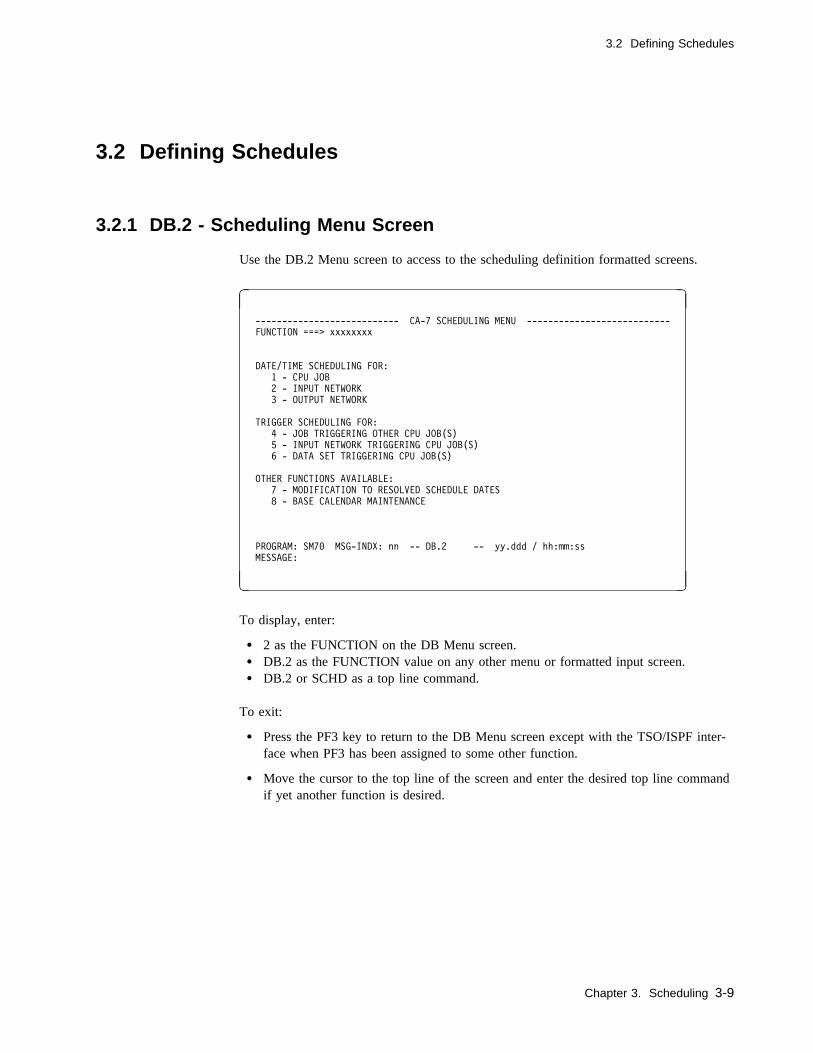
3.2 Defining Schedules
3.2 Defining Schedules
3.2.1 DB.2 - Scheduling Menu Screen
Use the DB.2 Menu screen to access to the scheduling definition formatted screens.
� �
--------------------------- CA-7 SCHEDULING MENU ---------------------------
FUNCTION ===> xxxxxxxx
DATE/TIME SCHEDULING FOR:
1 - CPU JOB
2 - INPUT NETWORK
3 - OUTPUT NETWORK
TRIGGER SCHEDULING FOR:
4 - JOB TRIGGERING OTHER CPU JOB(S)
5 - INPUT NETWORK TRIGGERING CPU JOB(S)
6 - DATA SET TRIGGERING CPU JOB(S)
OTHER FUNCTIONS AVAILABLE:
7 - MODIFICATION TO RESOLVED SCHEDULE DATES
8 - BASE CALENDAR MAINTENANCE
PROGRAM: SM7� MSG-INDX: nn -- DB.2 -- yy.ddd / hh:mm:ss
MESSAGE:
( )
To display, enter:
� 2 as the FUNCTION on the DB Menu screen.� DB.2 as the FUNCTION value on any other menu or formatted input screen.� DB.2 or SCHD as a top line command.
To exit:
� Press the PF3 key to return to the DB Menu screen except with the TSO/ISPF inter-face when PF3 has been assigned to some other function.
� Move the cursor to the top line of the screen and enter the desired top line commandif yet another function is desired.
Chapter 3. Scheduling 3-9

3.2 Defining Schedules
3.2.1.1 Usage Notes
Select the desired function by entering the appropriate FUNCTION value and pressing theEnter key.
3-10 CA-7 3.3 Database Maintenance Guide

3.2 Defining Schedules
3.2.2 DB.2.1 - CPU Job Scheduling Screen
Use this screen to define or review options taken for CPU jobs with date/time schedules.
� �
------------------------- CA-7 CPU JOB SCHEDULING --------------------------
FUNCTION: xxxxxxxx (CLEAR,DELETE,EDIT,FE,FETCH,REPL,RESOLV,SAVE)
JOB: xxxxxxxx
SCAL: xx (DEFAULT SCAL ID FOR ADDS)
SCHID-COUNT: nnn
PROGRAM: SM71 MSG-INDX: nn -- DB.2.1 -- yy.ddd / hh:mm:ss
MESSAGE:
( )
To display, enter:
� 1 as the FUNCTION on the DB.2 Menu screen.� 2.1 as the FUNCTION on the DB Menu screen.� DB.2.1 as the FUNCTION value on any other menu or formatted input screen.� DB.2.1 or SCHD,JOB as a top line command.
To exit:
� Press the PF3 key to return to the DB.2 Menu screen except with the TSO/ISPFinterface when PF3 has been assigned to some other function.
� Move the cursor to the top line of the screen and enter the desired top line commandif yet another function is desired.
Chapter 3. Scheduling 3-11
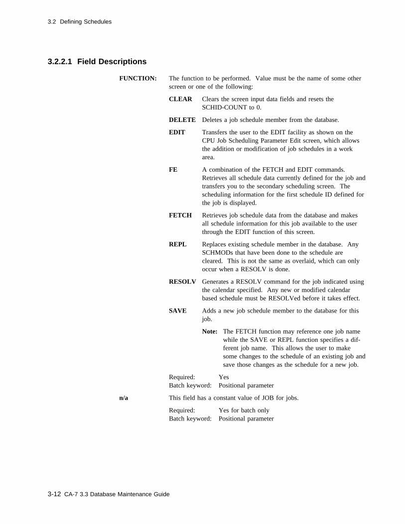
3.2 Defining Schedules
3.2.2.1 Field Descriptions
FUNCTION: The function to be performed. Value must be the name of some otherscreen or one of the following:
CLEAR Clears the screen input data fields and resets theSCHID-COUNT to 0.
DELETE Deletes a job schedule member from the database.
EDIT Transfers the user to the EDIT facility as shown on theCPU Job Scheduling Parameter Edit screen, which allowsthe addition or modification of job schedules in a workarea.
FE A combination of the FETCH and EDIT commands.Retrieves all schedule data currently defined for the job andtransfers you to the secondary scheduling screen. Thescheduling information for the first schedule ID defined forthe job is displayed.
FETCH Retrieves job schedule data from the database and makesall schedule information for this job available to the userthrough the EDIT function of this screen.
REPL Replaces existing schedule member in the database. AnySCHMODs that have been done to the schedule arecleared. This is not the same as overlaid, which can onlyoccur when a RESOLV is done.
RESOLV Generates a RESOLV command for the job indicated usingthe calendar specified. Any new or modified calendarbased schedule must be RESOLVed before it takes effect.
SAVE Adds a new job schedule member to the database for thisjob.
Note: The FETCH function may reference one job namewhile the SAVE or REPL function specifies a dif-ferent job name. This allows the user to makesome changes to the schedule of an existing job andsave those changes as the schedule for a new job.
Required: YesBatch keyword: Positional parameter
n/a This field has a constant value of JOB for jobs.
Required: Yes for batch onlyBatch keyword: Positional parameter
3-12 CA-7 3.3 Database Maintenance Guide

3.2 Defining Schedules
JOB: The required job name for which schedule information is being defined.
Size/Type: 1 to 8 alphanumeric charactersRequired: YesBatch keyword: JOB
SCAL: This field indicates the last 2 characters of the default base calendar IDto be used for schedule resolution. The complete calendar ID used isin the format SCALnnxx where nn is the current year and xx is thevalue entered. This value is used for all SCHIDs that do not have aspecific value coded on the DB.2.1-E screen.
Size/Type: 2 alphanumeric charactersRequired: Yes - for the SAVE, REPL, and RESOLV functions
No - for CLEAR, DELETE, and EDIT functionsAutomatically supplied for FETCH or FE functions
Batch keyword: SCAL
SCHID-COUNT:A system-generated field which tells the user how many schedule IDscurrently exist in the Edit Work File.
3.2.2.2 Usage Notes
You must resolve schedules defined on this screen against the specified base calendarwith the RESOLV function or top line command before CA-7 automatic scheduling cancommence.
Chapter 3. Scheduling 3-13
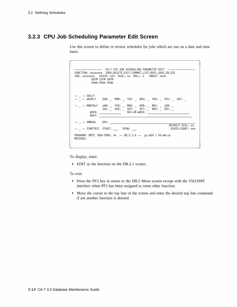
3.2 Defining Schedules
3.2.3 CPU Job Scheduling Parameter Edit Screen
Use this screen to define or review schedules for jobs which are run on a date and timebasis.
� �
------------------ CA-7 CPU JOB SCHEDULING PARAMETER EDIT ------------------
FUNCTION: xxxxxxxx (ADD,DELETE,EXIT,FORMAT,LIST,REPL,SAVE,SR,SS)
JOB: xxxxxxxx SCHID: nnn SCAL: xx ROLL: x INDEX: nnnn
DOTM LDTM SBTM
hhmm hhmm hhmm
-- _ -- DAILY
-- _ -- WEEKLY SUN: _ MON: _ TUE: _ WED: _ THU: _ FRI: _ SAT: _
-- _ -- MONTHLY JAN: _ FEB: _ MAR: _ APR: _ MAY: _ JUN: _
JUL: _ AUG: _ SEP: _ OCT: _ NOV: _ DEC: _
WEEK: ______________ DAY-OF-WEEK: ___________________________
RDAY: ____________________________________________________________
-- _ -- ANNUAL DAY: _______________________________________________________
DEFAULT SCAL: xx
-- _ -- SYMETRIC START: ___ SPAN: ___ SCHID-COUNT: nnn
PROGRAM: SM72 MSG-INDX: nn -- DB.2.1-E -- yy.ddd / hh:mm:ss
MESSAGE:
( )
To display, enter:
� EDIT as the function on the DB.2.1 screen.
To exit:
� Press the PF3 key to return to the DB.2 Menu screen except with the TSO/ISPFinterface when PF3 has been assigned to some other function.
� Move the cursor to the top line of the screen and enter the desired top line commandif yet another function is desired.
3-14 CA-7 3.3 Database Maintenance Guide

3.2 Defining Schedules
3.2.3.1 Field Descriptions
FUNCTION: The function to be performed. Value must be the name of some otherscreen or one of the following:
ADD Adds a new SCHID to the work area.
DELETE Deletes a SCHID from the work area.
EXIT Returns the user to the DB.2.1 screen restoring theSCHID-COUNT and schedule data to that which existedwhen EDIT was initially entered and clears the workarea. Any changes made are ignored.
FORMAT Clears the screen of user input data.
LIST Lists all existing SCHIDs, one per screen.
REPL Replaces an existing SCHID in work area. (Beforereplacing, you must use the LIST command to displaythe existing record.)
SAVE Updates SCHID-COUNT and SCHID information, andreturns the user to the DB.2.1 screen. Work area data(changes) are retained but the database is not updated.
SR Combination function which results in a SAVE, a returnto the DB.2.1 screen, and a subsequent REPL to replacean existing schedule in the database. Saves all scheduleIDs into the Active Area and replaces them in the CA-7database. If not specified, the scheduling changes arelost once leaving this screen. Entering the SR functionautomatically returns you to the prior scheduling screen.
SS Combination function which results in a SAVE, a returnto the DB.2.1 screen, and a subsequent SAVE to add anewly defined schedule in the database.
Required: YesBatch keyword: Positional parameter
JOB This is informational only. It reflects the job name from the previousscreen.
SCHID: The numeric schedule ID on which the user wishes to perform thespecified action.
Size/Type: 1 to 3 numeric characters from 1 through 255Required: YesBatch keyword: SCHID
Chapter 3. Scheduling 3-15

3.2 Defining Schedules
SCAL The override of the default SCAL for this SCHID. If this SCHID isusing the default, this field is blank.
Size/Type 2 alphanumeric charactersRequired: NoBatch keyword: SCAL
ROLL: Specifies the desired action to be taken when a schedule day falls on abase calendar nonavailable processing day. This is not used if theDAILY option is used. If used, the value must be one of thefollowing:
B Roll the schedule back to the previous available processing dayin the Base Calendar.
F Roll the schedule forward to the next available processing day.
N Do not roll. Schedule day must stand.
D Do not roll and do not schedule.
Default: DRequired: NoBatch keyword: ROLL
INDEX: Specifies an adjustment to schedule days. After exercising the ROLLoption, the schedule is adjusted, forward for plus or backward forminus, by the number of working days entered.
Size/Type: 4 numeric characters specified as Innn where I canbe plus (unsigned) or minus (-) and nnn can be 0 to365 days
Required: NoBatch keyword: INDEX
You can use this field together with the RDAY field to schedule a jobto run 3 work days before the 15th of the month: specify -3 in theINDEX field, X in the MONTHLY field, and 15 in the RDAY field.
DOTM The due-out time of day for this schedule ID.
Size/Type: 4 numeric characters specified as hhmm where hhcan be 00 through 24 and mm can be 00 through 59
Required: Yes - for ADD and REPL functionsNo - for DELETE, EXIT, FORMAT, LIST, SAVE,SR, and SS functions
Batch keyword: TIME
In batch format, this field and the next two fields must be provided asa list of hhmm values as follows:
TIME=(dueout,lead,submit)
3-16 CA-7 3.3 Database Maintenance Guide
3.2 Defining Schedules
LDTM The lead time (elapsed or clock time) for this schedule ID. Lead timespecifies the amount of time necessary to ensure that the job com-pletes before its due-out time plus any additional time required toperform setup functions. This value is used for deadline promptingand forecasting only if elapsed (clock) time on the DB.1 screen is setto 2359.
Size/Type: 4 numeric characters specified as hhmm where hhcan be 00 through 24 and mm can be 00 through 59
Required: Yes - for ADD and REPL functionsNo - for DELETE, EXIT, FORMAT, LIST, SAVE,SR, and SS functions
Batch keyword: TIME
SBTM The submit time of day for this schedule ID. If specified, the job isnot submitted before this time. If the submit time is before deadlinestart time, the submit time requirement will be automatically satisfiedwhen the job enters the queue. A submit time of zeros is the same asnot specifying it, and no submit time is set up.
Size/Type: 4 numeric characters specified as hhmm where hhcan be 00 through 24 and mm can be 00 through 59
Required: NoBatch keyword: TIME
DAILY Indicates that the user wishes to define a daily schedule. Daily meansevery available processing day as defined by the Base Calendar. Thisis selected by entering an X or Y. If DAILY is used, the ROLL func-tion has no effect.
Required: NoBatch keyword: DAILY
WEEKLY Indicates that the user wishes to define a weekly schedule. This isselected by entering an X or Y. If WEEKLY is used, the run days ofthe week must be selected using the SUN through SAT fields.
Required: NoBatch keyword: WEEKLY
Chapter 3. Scheduling 3-17

3.2 Defining Schedules
SUN: thru SAT: These fields are used to define specific days of the week on which thejob is to be run.
Online: Place an X in screen field names SUN through SAT as nec-essary to indicate the weekly run days.
Required: Yes (if WEEKLY is used)Batch keyword: DAYS
Batch: Place an X in any of the 7 positions following the batchkeyword DAYS to indicate weekly run days. A day is skipped byomitting an X for that day. For example, if a job is to run weekly onSunday, Wednesday and Saturday, the user would specify:
DAYS=(X,,,X,,,X)
MONTHLY Indicates that the user wants to define a monthly schedule. If thisfield is used, the user may optionally specify on which particularmonths the job is to run. If specific months are not specified in theJAN through DEC fields, all months are assumed. Selection is indi-cated by entering an X or Y.
At least WEEK(S) and DAY-OF-WEEK (DOW) or RDAY(S) mustalso be specified if MONTHLY is used.
Required: NoBatch keyword: MONTHLY
JAN: thru DEC: Online: Place an X in screen field names JAN through DEC to indi-cate the run months during the year. Used with MONTHLY.
Default: Every month if MONTHLY is used and no monthsare chosen
Required: NoBatch keyword: MONTHS
Batch: Place an X in any of the 12 positions following the batchkeyword MONTHS to indicate run months. A month is skipped byomitting an X for that month. For example, if a job is to run inJanuary, June, July and November, the user would specify:
MONTHS=(X,,,,,X,X,,,,X,)
3-18 CA-7 3.3 Database Maintenance Guide
3.2 Defining Schedules
WEEK: Specifies which weeks of the month the job is to run. The valuesspecified can be positive (unsigned), negative (-) or slash (/).
Positive values 1, 2, 3, 4, or 5 are used to indicate days of weekrelative to the beginning of the month. Negative values -0, -1, and -2are used to indicate occurrence of day of week relative to the end ofthe month. Slashes indicate NOT the following value. For example,a job that is to run on the first occurrence of day of week of everymonth and is also to run on the last occurrence of day of week of themonth would be entered as:
Online:WEEK:1,-0 (separated by blanks or commas)
Size/Type: 1 to 14 numeric charactersRequired: Yes (if MONTHLY and DAY-OF-WEEK are used)Batch keyword: WEEKS
Batch:WEEKS=1 -0 (separated by blanks)
DAY-OF-WEEK:Indicates which day(s) of the week the job is to be run. If used, eachday must be the first three letters of the desired run day(s) just as itappears on the screen following the weekly field (for example, SUN,MON, and so forth).
Online:DAY-OF-WEEK:TUE,THU(separated by blanks or commas)
Size/Type: 3 to 27 alphanumeric charactersRequired: Only if WEEK is used with MONTHLYBatch keyword: DOW
Batch:DOW=TUE THU (separated by blanks)
Chapter 3. Scheduling 3-19

3.2 Defining Schedules
RDAY: Specifies relative days of the month on which the job is to run. Usedwith MONTHLY. A day relative to the beginning or end of themonth is specified. If a positive (unsigned) value is used, the job runsthat day relative to the first of the month. Negative (-) values areused to indicate run days relative to the end of the month.
Additionally, if there are days of the month when this job is not torun, a slash (/) may be used with the unsigned or negative values.Valid positive values range from 1 to 31. Valid negative values rangefrom -0 to -30.
Size/Type: 1 to 60 numeric charactersRequired: NoBatch keyword: RDAYS
To understand the meaning and use of RDAY, assume a job is to rundaily, but not on the first and last day of each month. The user couldselect DAILY, MONTHLY and specify:
Online:RDAY:/1,/-0 (separated by a blank or comma)
Batch:RDAYS=/1 /-0 (separated by a blank)
Note: RDAY(S) represents calendar days, unless the base calendarwas generated with OPTIONS=SCHDYONLY, in which caseRDAY(S) represents processing days.
ANNUAL Defines an annual schedule. The user selects this type of schedule byplacing an X or Y in this optional field. If ANNUAL is used, DAYis required.
Required: NoBatch keyword: ANNUAL
DAY: Indicates on which days of the annual schedule the user wishes to runthe job. Days are entered as 1 through 366 and are prefixed by posi-tive (unsigned) or slash (/) values. Slash indicates NOT this day.
Size/Type: 1 to 55 numeric charactersRequired: Yes (if ANNUAL is used)Batch keyword: ANNDAYS
For example, if a job is to run on days 121, 132, 240, and 241, but isnot to run on days 122, 242, and 1, the user would specify:
Online:DAY:/1,121,/122,132,240,241,/242(separated by blanks or commas)
Batch:ANNDAYS=/1 121 /122 132 240 241 /242(separated by blanks)
3-20 CA-7 3.3 Database Maintenance Guide
3.2 Defining Schedules
By default, days not specifically defined as processing days (with anumber) are considered as unscheduled days unless another field, suchas WEEKLY or MONTHLY schedules those days. The use of theslash (/) examples given above is only provided here to illustrate theformat of the date specification.
The following illustrates a more practical example of using "not days"(/). Assume a job's schedule has been defined as every Friday byselecting WEEKLY and FRI. During the week containing Julian day177 (a Friday), the job is to run on Thursday (176) instead of Friday.The user would select WEEKLY, FRI, ANNUAL, and specify:
Online:DAY:/177,176
Batch:ANNDAYS=/177 176
When specifying annual days in a schedule definition, keep in mindwhether this schedule is to be resolved for a January throughDecember schedule or a July through June schedule. For Januarythrough December resolutions, the Julian dates specified are simplyfor the year resolved.
For July through June resolutions, July through December dates arefor the current year. January through June dates are for the next year.
DEFAULT SCAL:This reflects the default SCAL value from the previous screen. Thisvalue applies to all SCHIDs unless the SCAL field is supplied on thecurrent screen.
SYMETRIC This field is used in combination with the START and SPAN fields todefine a symmetric schedule. With this option, schedules are definedas beginning on the date specified with the START field and recurringevery nnn days as specified with the SPAN field. (This field is mis-spelled intentionally to provide compatibility with the batch keywordwhich cannot exceed 8 characters.) The selection of this type ofschedule is made by entering an X or Y.
Required: NoBatch keyword: SYMETRIC
Chapter 3. Scheduling 3-21
3.2 Defining Schedules
START: This field is used in combination with SPAN and SYMETRIC todefine a symmetric schedule. This field is required when theSYMETRIC option is taken. Value must be specified as the Julianday of the year on which the symmetric schedule is to begin. Thisvalue should be evaluated yearly before schedule resolution and mayneed to be changed each year.
If the schedule will be resolved on a July-June basis, the start datemust be within the first of the two years in which the schedule over-laps. For January-December schedules, it is simply relative to January1 of the year specified on a RESOLV command.
If the calendar against which this SCHID will be resolved does nothave the OPTIONS=SCHDYONLY, the START day will be adjustedeach year to maintain the job's symmetric schedule from the job's ori-ginal specified START day.
If the calendar against which the SCHID will be resolved was gener-ated with overall available processing days only(OPTIONS=SCHDYONLY), the start date must specify the first dayon which the job would actually run. This requires manually setting(verifying) the START value each year before the RESOLV.
If a nonprocessing day is specified, the start day is the next processingday found in the calendar. For example, if January 1 is a nonproc-essing day and the calendar was generated withOPTIONS=SCHDYONLY, and 1 is specified as the START day,January 2 is the actual START day (provided it is an available proc-essing day). SPAN is based from January 2 in this example ratherthan January 1.
For other types of calendars, the start date is determined at RESOLVtime based on the ROLL and INDEX options taken.
Size/Type: 3 numeric characters specified as Julian day of theyear from 1 to 365
Required: NoBatch keyword: START
3-22 CA-7 3.3 Database Maintenance Guide
3.2 Defining Schedules
SPAN: This field is used in combination with SYMETRIC and START todefine symmetric schedules. This field is required if the SYMETRICoption is taken. When used, specifies the number of days betweenscheduled processing cycles.
If the calendar against which the SCHID will be resolved was gener-ated with processing days only (OPTIONS=SCHDYONLY), theSPAN value is specified as the number of available on processingdays off between and including the next processing date as opposed tothe actual number of days. With this type of calendar, the ROLL andINDEX options serve no practical purpose. For other calendar types,the SPAN value is specified as the number of calendar days betweenprocessing cycles and the ROLL and INDEX options can be used asnecessary.
Size/Type: 1 to 3 numeric characters from 1 to 255Required: NoBatch keyword: SPAN
SCHID-COUNT: A system-generated field which tells the user the current schedule IDcount for this job.
3.2.3.2 Batch Input Example
This batch input example adds schedule ID 1 for job CA07XX01 for a daily schedule,using calendar 03, with a due-out time of 0800, and a lead time of 1 hour.
SCHD
JOB
EDIT
ADD,SCHID=1,DAILY=Y,TIME=(�8��,�1��)
SAVE
SAVE,JOB=CA�7XX�1,SCAL=�3
DBM
Chapter 3. Scheduling 3-23

3.2 Defining Schedules
3.2.4 DB.2.2 - Input Network Scheduling Screen
Use this screen to define or review scheduling options for input networks.
� �
---------------------- CA-7 INPUT NETWORK SCHEDULING -----------------------
FUNCTION: xxxxxxxx (CLEAR,DELETE,EDIT,FE,FETCH,REPL,RESOLV,SAVE)
NETWORK: xxxxxxxx
SCAL: xx (DEFAULT SCAL ID FOR ADDS)
SCHID-COUNT: nnn
PROGRAM: SM71 MSG-INDX: nn -- DB.2.2 -- yy.ddd / hh:mm:ss
MESSAGE:
( )
To display, enter:
� 2 as the FUNCTION on the DB.2 Menu screen.� 2.2 as the FUNCTION on the DB Menu screen.� DB.2.2 as the FUNCTION on any other menu or formatted input screen.� DB.2.2 or SCHD,INWK as a top line command.
To exit:
� Press the PF3 key to return to the DB.2 Menu screen except with the TSO/ISPFinterface when PF3 has been assigned to some other function.
� Move the cursor to the top line of the screen and enter the desired top line commandif yet another function is desired.
3-24 CA-7 3.3 Database Maintenance Guide
3.2 Defining Schedules
3.2.4.1 Field Descriptions
FUNCTION: The function to be performed. Value must be the name of some otherscreen or one of the following:
CLEAR Clears the screen input data fields and resets theSCHID-COUNT to 0.
DELETE Deletes an input network schedule member from the data-base.
EDIT Transfers the user to the EDIT facility as shown on theInput Network Scheduling Parameter Edit screen. Thisallows the addition or modification of input network sched-ules in a work area.
FE Combination of FETCH and EDIT.
FETCH Retrieves input network schedule data from the databaseand makes all of the schedule information for this inputnetwork available to the user through the EDIT function ofthis screen.
REPL Replaces an existing schedule in the database.
RESOLV Generates a RESOLV command for the network indicatedusing the calendar specified. Any new or modified cal-endar based schedule must be RESOLVed before it takeseffect.
SAVE Adds a new schedule to the database for this input network.The user may SAVE to any input network name but thenumber of stations specified on the EDIT screen for thenetwork must equal the number defined for the network.
Required: YesBatch keyword: Positional parameter
n/a This field has a constant value of INWK for input networks.
Required: Yes for batch onlyBatch keyword: Positional parameter
NETWORK: The input network name for which schedule information is beingdefined.
Size/Type: 1 to 8 alphanumeric charactersRequired: YesBatch keyword: NETWORK
Chapter 3. Scheduling 3-25
3.2 Defining Schedules
SCAL: This field indicates the last 2 characters of the default base calendar IDto be used for Schedule Resolution. The complete calendar ID used isin the format SCALnnxx where nn is the current year and xx is thevalue entered. This value is used for all SCHIDs that do not have avalue coded on the DB.2.2-E screen.
Size/Type: 2 alphanumeric charactersRequired: Yes - for SAVE, REPL, and RESOLV functions
No - for CLEAR, DELETE, EDIT, FE, and FETCHfunctions
Batch keyword: SCAL
SCHID-COUNT:A system-generated field which shows how many schedule IDs cur-rently exist for this network.
3-26 CA-7 3.3 Database Maintenance Guide
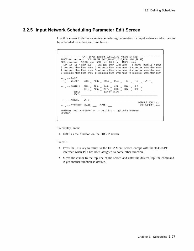
3.2 Defining Schedules
3.2.5 Input Network Scheduling Parameter Edit Screen
Use this screen to define or review scheduling parameters for input networks which are tobe scheduled on a date and time basis.
� �
--------------- CA-7 INPUT NETWORK SCHEDULING PARAMETER EDIT ---------------
FUNCTION: xxxxxxxx (ADD,DELETE,EXIT,FORMAT,LIST,REPL,SAVE,SR,SS)
NWK: xxxxxxxx SCHID: nnn SCAL: xx ROLL: x INDEX: nnnn
STATION DOTM LDTM DODY STATION DOTM LDTM DODY STATION DOTM LDTM DODY
1 xxxxxxxx hhmm hhmm nnnn 2 xxxxxxxx hhmm hhmm nnnn 3 xxxxxxxx hhmm hhmm nnnn
4 xxxxxxxx hhmm hhmm nnnn 5 xxxxxxxx hhmm hhmm nnnn 6 xxxxxxxx hhmm hhmm nnnn
7 xxxxxxxx hhmm hhmm nnnn 8 xxxxxxxx hhmm hhmm nnnn 9 xxxxxxxx hhmm hhmm nnnn
-- _ -- DAILY
-- _ -- WEEKLY SUN: _ MON: _ TUE: _ WED: _ THU: _ FRI: _ SAT: _
-- _ -- MONTHLY JAN: _ FEB: _ MAR: _ APR: _ MAY: _ JUN: _
JUL: _ AUG: _ SEP: _ OCT: _ NOV: _ DEC: _
WEEK: ______________ DAY-OF-WEEK: __________________________
RDAY: ____________________________________________________________
-- _ -- ANNUAL DAY: _______________________________________________________
DEFAULT SCAL: xx
-- _ -- SYMETRIC START: ___ SPAN: ___ SCHID-COUNT: nnn
PROGRAM: SM72 MSG-INDX: nn -- DB.2.2-E -- yy.ddd / hh:mm:ss
MESSAGE:
( )
To display, enter:
� EDIT as the function on the DB.2.2 screen.
To exit:
� Press the PF3 key to return to the DB.2 Menu screen except with the TSO/ISPFinterface when PF3 has been assigned to some other function.
� Move the cursor to the top line of the screen and enter the desired top line commandif yet another function is desired.
Chapter 3. Scheduling 3-27
3.2 Defining Schedules
3.2.5.1 Field Descriptions
FUNCTION: The function to be performed. Value must be the name of some otherscreen or one of following:
ADD Adds a new SCHID to the work area.
DELETE Deletes a SCHID from the work area.
EXIT Returns the user to the DB.2.2 screen and restores theSCHID-COUNT and schedule data to that which existedwhen EDIT was initially entered and clears the work area.
FORMAT Clears the screen of user input data.
LIST Lists all SCHIDs, one per screen.
REPL Replaces an existing SCHID in the work area.
SAVE Updates SCHID-COUNT and SCHID information andreturns the user to the DB.2.2 screen. Work area data(changes) are retained but the database is not updated.
SR Combination function which results in a SAVE, a returnto the DB.2.2 screen, and a subsequent REPL to replacean existing schedule in the database. Saves all scheduleIDs into the Active Area and replaces them in the CA-7database. If not specified, the scheduling changes are lostonce leaving this screen. Entering the SR function auto-matically returns you to the prior scheduling screen.
SS Combination function which results in a SAVE, a returnto the DB.2.2 screen, and a subsequent SAVE to add anewly defined schedule in the database.
Required: YesBatch keyword: Positional parameter
NWK This is informational only. It reflects the network name from the pre-vious screen.
SCHID: The numeric schedule ID on which the user wishes to perform thespecified action.
Size/Type: 1 to 3 numeric characters from 1 to 255Required: NoBatch keyword: SCHID
SCAL: This is the override of the default SCAL for this SCHID. If thisSCHID is using the default, this field is blank.
Size/Type: 2 alphanumeric charactersRequired: NoBatch keyword: SCAL
3-28 CA-7 3.3 Database Maintenance Guide
3.2 Defining Schedules
ROLL: Specifies the desired action to be taken when a schedule day falls on abase calendar nonavailable processing day. If used, the value must beone of the following:
B Roll the schedule back to the previous available processing day inthe Base Calendar.
F Roll the schedule forward to the next available processing day.
N Do not roll. Schedule day must stand.
D Do not roll and do not schedule.
Default: DRequired: NoBatch keyword: ROLL
INDEX: A field used to specify an adjustment to schedule days. After exer-cising the ROLL option, the schedule is adjusted, forward or backward,by the number of working days entered.
Size/Type: 1 to 4 numeric characters specified as Innn where Ican be plus (unsigned) or minus (-) and nnn can be 0to 365 days
Required: NoBatch keyword: INDEX
STATION Network workstation names. Up to nine workstations are listed.Station names are listed in the sequence in which their tasks are to beperformed (that is, as defined for the network). The same station namemay appear multiple times in the list. This field is for station identifi-cation purposes only. For batch, see the note under the TIME batchkeyword.
Size/Type: 1 to 8 alphanumeric charactersRequired: NoBatch keyword: Not applicable (see TIME)
DOTM This is the due-out time of day for the network workstation using thisschedule ID.
Size/Type: 1 to 4 numeric characters specified as hhmm, wherehh can be 00 through 24 and mm can be 00 through59
Required: Yes - for ADD or REPL functionsNo - for DELETE, EXIT, FORMAT, LIST, SAVE,SR, or SS functions
Batch keyword: TIME
Note for batch input:
TIME=(dotm1,ldtm1,dody1,dotm2,ldtm2,dody2,...,dotmn,ldtmn,dodyn)
must be used, where the numeric value (or n) corresponds to the rela-tive number of the station.
Chapter 3. Scheduling 3-29
3.2 Defining Schedules
LDTM The lead time for the workstation for this schedule ID. This is theamount of elapsed time necessary to ensure that the station completesits task by the scheduled due-out time.
Size/Type: 1 to 4 numeric characters specified as hhmm, wherehh can be 00 through 24 and mm can be 00 through59
Required: Yes - for ADD or REPL functionsNo - for DELETE, EXIT, FORMAT, LIST, SAVE,SR, or SS functions
Batch keyword: TIME
DODY The due-out day for the workstation in the network for this scheduleID. It is always relative to the first workstation in the network. Itindicates the number of days elapsed from the first workstation.
Size/Type: 1 to 4 numeric characters from 0 through 255Default: 0Required: Yes (if the lead time (elapsed time) between work-
stations in a network causes the schedule to cross anymidnight boundary)
Batch keyword: TIME
DAILY Indicates that the user wishes to define a daily schedule. Daily meansevery available processing day as defined by the Base Calendar. Thisis indicated by entering an X or Y.
Required: NoBatch keyword: DAILY
WEEKLY Indicates that the user wishes to define a weekly schedule. This isselected by entering an X or Y. If WEEKLY is used, the run days ofthe week must be selected using the SUN thru SAT fields.
Required: NoBatch keyword: WEEKLY
SUN: thru SAT:These fields are used to define specific days of the week on which thenetwork is to be run.
Online: Place an X in screen field names SUN through SAT to indi-cate the weekly run days.
Required: Yes (if WEEKLY is used)Batch keyword: DAYS
3-30 CA-7 3.3 Database Maintenance Guide
3.2 Defining Schedules
Batch: Place an X in any of the 7 positions following the batchkeyword DAYS to indicate weekly run days. A day is skipped byomitting an X for that day. For example, if a network is to run weeklyon Sunday, Wednesday and Saturday, the user would specify:
DAYS=(X,,,X,,,X)
MONTHLY Indicates that the user wants to define a monthly schedule. If this fieldis used, the user may specify on which particular months the network isto run. If specific months are not specified in the JAN thru DECfields, all months are assumed. Selection is indicated by entering an Xor Y.
Required: NoBatch keyword: MONTHLY
At least WEEK(S) and DAY-OF-WEEK (DOW) or RDAY(S) must bespecified if MONTHLY is used.
JAN: thru DEC:Online: Place an X in screen field names JAN through DEC to indi-cate the run months during the year. Used with MONTHLY.
Default Every month if MONTHLY is used and no monthsare chosen
Required: NoBatch keyword: MONTHS
Batch: Place an X in any of the 12 positions following the batchkeyword MONTHS to indicate run months. A month is skipped byomitting an X for that month. For example, if a network is to run inJanuary, June, July and November, the user would specify:
MONTHS=(X,,,,,X,X,,,,X,)
WEEK: Specifies which weeks of the month the network is to run. Used withMONTHLY and DAY-OF-WEEK. The values specified can be posi-tive (unsigned), negative (-) or slash (/).
Positive values 1, 2, 3, 4, or 5 are used to indicate which occurrence ofday of week relative to the beginning of the month. Negative values-0, -1, -2, -3, or -4 are used to indicate which occurrence of day ofweek relative to the end of the month. Slashes indicate it is not thefollowing value.
Size/Type: 1 to 14 numeric charactersRequired: NoBatch keyword: WEEKS
Chapter 3. Scheduling 3-31

3.2 Defining Schedules
For example, a network that is to run on the first week of every monthand is also to run on the last week of the month, would be entered as:
Online:WEEK:1,-0 (separated by blanks or commas)
Batch:WEEKS=1 -0 (separated by blanks)
DAY-OF-WEEK:Indicates which day of the week the network is to be run. Used withWEEK and MONTHLY. If used, must be the first three letters of thedesired run day just as it appears on the screen following the weeklyfield (for example, SUN, MON, and so forth).
Online:DAY-OF-WEEK:TUE,THU(separated by blanks or commas)
Size/Type: 3 to 27 alphanumeric charactersRequired: Yes (if WEEK is used)Batch keyword: DOW
Batch:DOW=TUE THU (separated by blanks)
RDAY: This field is used to specify relative days of the month on which thenetwork is to run. Used with MONTHLY. A day relative to thebeginning or end of the month is specified. If a positive (unsigned)value is used, the network runs that day relative to the first of themonth. Negative (-) values are used to indicate run days relative to theend of the month.
Additionally, if there are days of the month when this network is not torun, a slash (/) may be used with the unsigned or negative values. Validpositive values range from 1 to 31. Valid negative values range from-0 to -30.
Size/Type: 1 to 60 numeric charactersRequired: NoBatch keyword: RDAYS
To understand the meaning and use of RDAY, assume a network is torun daily, but not on the first or last day of each month. The usercould select DAILY, MONTHLY and specify:
Online:RDAY:/1,/-0 (separated by a blank or comma)
Batch:RDAYS=/1 /-0 (separated by a blank)
Note: RDAY(S) represents calendar days, unless the base calendarwas generated with OPTIONS=SCHDYONLY, in which caseRDAY(S) represents processing days.
3-32 CA-7 3.3 Database Maintenance Guide

3.2 Defining Schedules
ANNUAL Defines an annual schedule. The user selects this type of schedule byentering an X or Y in this field. If ANNUAL is used, DAY must alsobe specified.
Required: NoBatch keyword: ANNUAL
DAY: Indicates on which days of the annual schedule the user wishes to runthe network. Days are entered as 1 through 366 and are prefixed bypositive (unsigned) or slash (/) values. Slash indicates NOT this day.
Size/Type: 1 to 55 numeric charactersRequired: Yes (if the ANNUAL option above is chosen)Batch keyword: ANNDAYS
For example, if a network is to run on days 121, 132, 240, and 241, butis not on days 122, 242, and 1, you would specify:
Online:DAY:/1,121,/122,132,240,241,/242(separated by blanks or commas)
Batch:ANNDAYS=/1 121 /122 132 240 241 /242(separated by blanks)
By default, days not specifically defined as processing days (with anumber) are considered as unscheduled days unless another field suchas WEEKLY or MONTHLY schedules those days. The use of theslash (/) examples given previously is only provided here to illustratethe format of the date specification.
The following illustrates a more practical example of using "not days"(/). Assume a network schedule has been defined as every Friday byselecting WEEKLY and FRI. During the week containing Julian day177 (Friday), the network is to run on Thursday (day 176) instead ofFriday. The user would select WEEKLY, FRI, ANNUAL and:
Online:DAY:/177,176
Batch:ANNDAYS=/177 176
When specifying annual days in a schedule definition, keep in mindwhether this schedule will be resolved for a January through Decemberschedule or a July through June schedule. For January throughDecember resolutions, the Julian dates specified are simply for the yearresolved.
For July through June resolutions, July through December dates are forthe current year. January through June dates are for the next year.
Chapter 3. Scheduling 3-33

3.2 Defining Schedules
DEFAULT SCAL:This reflects the default SCAL value from the previous screen. Thisvalue applies to all SCHIDs unless the SCAL field is supplied on thecurrent screen.
SYMETRIC This field is used with the START and SPAN fields to define a sym-metric schedule. (This field is misspelled intentionally on the screen toprovide compatibility with the batch keyword which cannot exceed 8characters in length.) The selection is made by entering an X or Y.With this option, schedules are defined as beginning on the date speci-fied with the START field and recurring every nnn days as specified inthe SPAN field.
Required: NoBatch keyword: SYMETRIC
START: This field is used with the SYMETRIC field to set a starting day.
Size/Type: 1 to 3 numeric characters specified as Julian dayfrom 1 to 365
Required: Yes (if SYMETRIC option is chosen)Batch keyword: START
If the schedule will be resolved on a July-June basis, the start date mustbe within the first of the two years in which the schedule overlaps. ForJanuary-December schedules, it is simply relative to January 1 of theyear specified on a RESOLV command.
If the calendar against which this SCHID will be resolved does nothave the OPTIONS=SCHDYONLY, the START day will be adjustedeach year to maintain the job's symmetric schedule from the job's ori-ginal specified START day.
If the calendar against which the SCHID will be resolved was gener-ated with overall available processing days only(OPTIONS=SCHDYONLY), the start date must specify the first day onwhich the network would actually run. This requires manually setting(verifying) the START value each year before the RESOLV.
If a nonprocessing day is specified, the start day is the next processingday found in the calendar. For example, if January 1 is a nonproc-essing day and the calendar was generated withOPTIONS=SCHDYONLY, and 1 is specified as the START day,January 2 is the actual START day (provided it is an available proc-essing day). SPAN is based from January 2 in this example rather thanJanuary 1.
For other types of calendars, the start date is determined at RESOLVtime based on the ROLL and INDEX options taken.
3-34 CA-7 3.3 Database Maintenance Guide
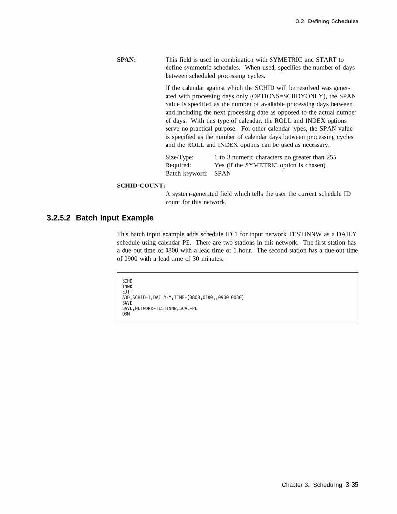
3.2 Defining Schedules
SPAN: This field is used in combination with SYMETRIC and START todefine symmetric schedules. When used, specifies the number of daysbetween scheduled processing cycles.
If the calendar against which the SCHID will be resolved was gener-ated with processing days only (OPTIONS=SCHDYONLY), the SPANvalue is specified as the number of available processing days betweenand including the next processing date as opposed to the actual numberof days. With this type of calendar, the ROLL and INDEX optionsserve no practical purpose. For other calendar types, the SPAN valueis specified as the number of calendar days between processing cyclesand the ROLL and INDEX options can be used as necessary.
Size/Type: 1 to 3 numeric characters no greater than 255Required: Yes (if the SYMETRIC option is chosen)Batch keyword: SPAN
SCHID-COUNT:A system-generated field which tells the user the current schedule IDcount for this network.
3.2.5.2 Batch Input Example
This batch input example adds schedule ID 1 for input network TESTINNW as a DAILYschedule using calendar PE. There are two stations in this network. The first station hasa due-out time of 0800 with a lead time of 1 hour. The second station has a due-out timeof 0900 with a lead time of 30 minutes.
SCHD
INWK
EDIT
ADD,SCHID=1,DAILY=Y,TIME=(�8��,�1��,,�9��,��3�)
SAVE
SAVE,NETWORK=TESTINNW,SCAL=PE
DBM
Chapter 3. Scheduling 3-35
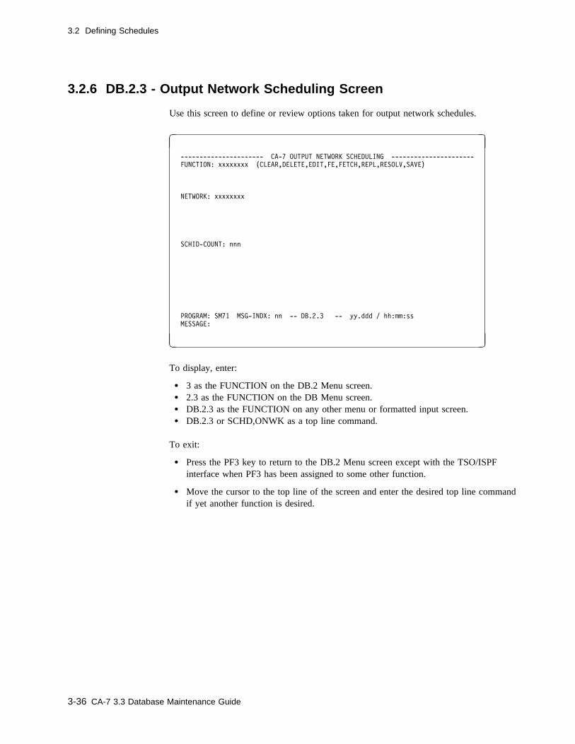
3.2 Defining Schedules
3.2.6 DB.2.3 - Output Network Scheduling Screen
Use this screen to define or review options taken for output network schedules.
� �
---------------------- CA-7 OUTPUT NETWORK SCHEDULING ----------------------
FUNCTION: xxxxxxxx (CLEAR,DELETE,EDIT,FE,FETCH,REPL,RESOLV,SAVE)
NETWORK: xxxxxxxx
SCHID-COUNT: nnn
PROGRAM: SM71 MSG-INDX: nn -- DB.2.3 -- yy.ddd / hh:mm:ss
MESSAGE:
( )
To display, enter:
� 3 as the FUNCTION on the DB.2 Menu screen.� 2.3 as the FUNCTION on the DB Menu screen.� DB.2.3 as the FUNCTION on any other menu or formatted input screen.� DB.2.3 or SCHD,ONWK as a top line command.
To exit:
� Press the PF3 key to return to the DB.2 Menu screen except with the TSO/ISPFinterface when PF3 has been assigned to some other function.
� Move the cursor to the top line of the screen and enter the desired top line commandif yet another function is desired.
3-36 CA-7 3.3 Database Maintenance Guide
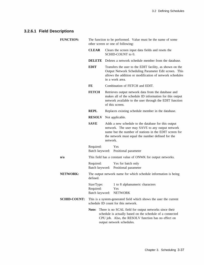
3.2 Defining Schedules
3.2.6.1 Field Descriptions
FUNCTION: The function to be performed. Value must be the name of someother screen or one of following:
CLEAR Clears the screen input data fields and resets theSCHID-COUNT to 0.
DELETE Deletes a network schedule member from the database.
EDIT Transfers the user to the EDIT facility, as shown on theOutput Network Scheduling Parameter Edit screen. Thisallows the addition or modification of network schedulesin a work area.
FE Combination of FETCH and EDIT.
FETCH Retrieves output network data from the database andmakes all of the schedule ID information for this outputnetwork available to the user through the EDIT functionof this screen.
REPL Replaces existing schedule member in the database.
RESOLV Not applicable.
SAVE Adds a new schedule to the database for this outputnetwork. The user may SAVE to any output networkname but the number of stations in the EDIT screen forthe network must equal the number defined for thenetwork.
Required: YesBatch keyword: Positional parameter
n/a This field has a constant value of ONWK for output networks.
Required: Yes for batch onlyBatch keyword: Positional parameter
NETWORK: The output network name for which schedule information is beingdefined.
Size/Type: 1 to 8 alphanumeric charactersRequired: YesBatch keyword: NETWORK
SCHID-COUNT: This is a system-generated field which shows the user the currentschedule ID count for this network.
Note: There is no SCAL field for output networks since theirschedule is actually based on the schedule of a connectedCPU job. Also, the RESOLV function has no effect onoutput network schedules.
Chapter 3. Scheduling 3-37
3.2 Defining Schedules
3.2.6.2 Usage Notes
If the network is connected to the CPU job with a DB.3.5 function, the network is sched-uled automatically whenever the connected CPU job is scheduled. However, the networkmust be scheduled with DB.2.3 so that time values may be given.
Optionally, for networks which direct the manual handling of SYSOUT type data, usersof CA-Dispatch and CA-7 RPT can have those products automatically issue a DMDNWcommand for the network. In those cases, the network must not be connected to a CPUjob with the DB.3.5 screen.
3-38 CA-7 3.3 Database Maintenance Guide

3.2 Defining Schedules
3.2.7 Output Network Scheduling Parameter Edit Screen
Use this screen to define or review individual workstation schedules in an output network.The output network's schedule cycles are based on the schedules of the jobs to which it isconnected.
� �
-------------- CA-7 OUTPUT NETWORK SCHEDULING PARAMETER EDIT ---------------
FUNCTION: xxxxxxxx (ADD,DELETE,EDIT,FORMAT,LIST,REPL,SAVE,SR,SS)
NWK: xxxxxxxx SCHID: nnn
STATION DOTM LDTM DODY STATION DOTM LDTM DODY STATION DOTM LDTM DODY
1 xxxxxxxx hhmm hhmm nnnn 2 xxxxxxxx hhmm hhmm nnnn 3 xxxxxxxx hhmm hhmm nnnn
4 xxxxxxxx hhmm hhmm nnnn 5 xxxxxxxx hhmm hhmm nnnn 6 xxxxxxxx hhmm hhmm nnnn
7 xxxxxxxx hhmm hhmm nnnn 8 xxxxxxxx hhmm hhmm nnnn 9 xxxxxxxx hhmm hhmm nnnn
SCHID-COUNT: nnn
PROGRAM: SM72 MSG-INDX: nn -- DB.2.3-E -- yy.ddd / hh:mm:ss
MESSAGE:
( )
To display, enter:
� EDIT as the function on the DB.2.3 screen.
To exit:
� Press the PF3 key to return to the DB.2 Menu screen except with the TSO/ISPFinterface when PF3 has been assigned to some other function.
� Move the cursor to the top line of the screen and enter the desired top line commandif yet another function is desired.
Chapter 3. Scheduling 3-39
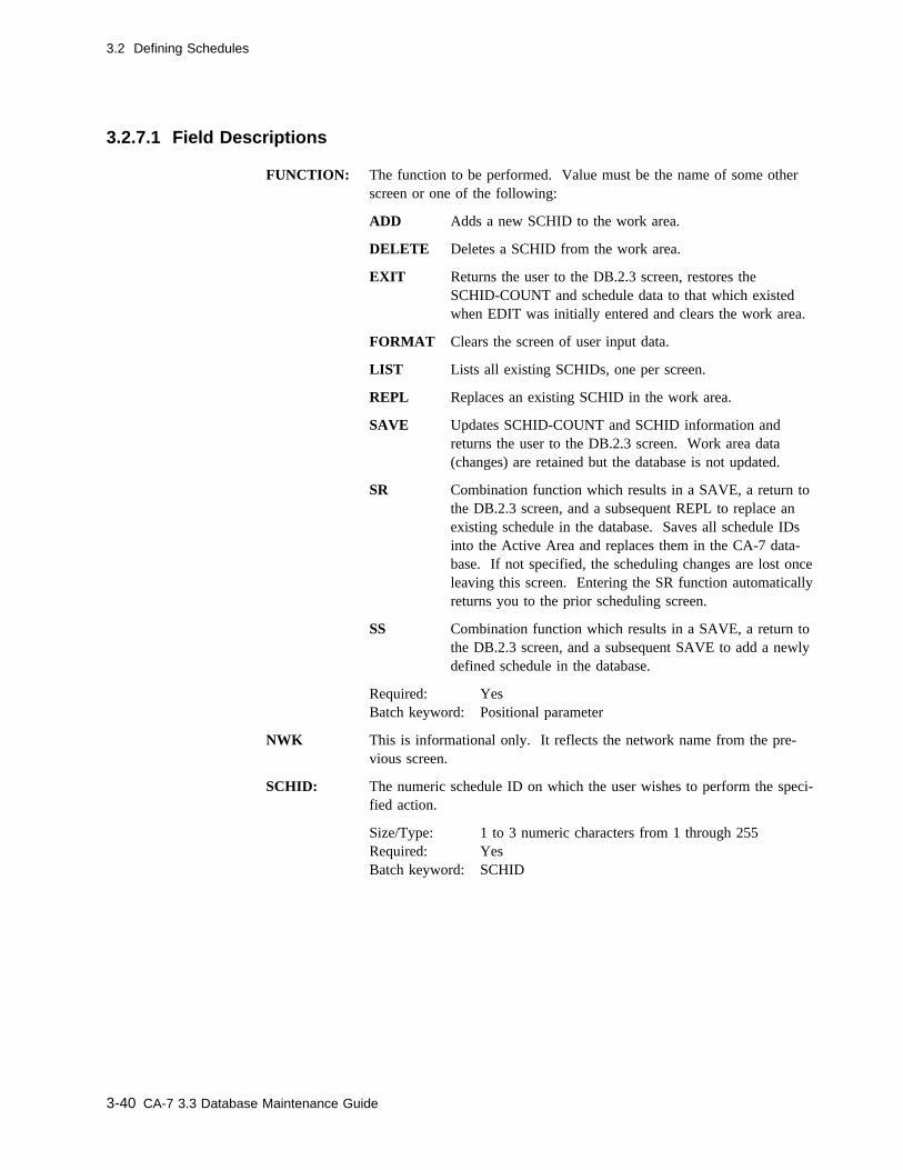
3.2 Defining Schedules
3.2.7.1 Field Descriptions
FUNCTION: The function to be performed. Value must be the name of some otherscreen or one of the following:
ADD Adds a new SCHID to the work area.
DELETE Deletes a SCHID from the work area.
EXIT Returns the user to the DB.2.3 screen, restores theSCHID-COUNT and schedule data to that which existedwhen EDIT was initially entered and clears the work area.
FORMAT Clears the screen of user input data.
LIST Lists all existing SCHIDs, one per screen.
REPL Replaces an existing SCHID in the work area.
SAVE Updates SCHID-COUNT and SCHID information andreturns the user to the DB.2.3 screen. Work area data(changes) are retained but the database is not updated.
SR Combination function which results in a SAVE, a return tothe DB.2.3 screen, and a subsequent REPL to replace anexisting schedule in the database. Saves all schedule IDsinto the Active Area and replaces them in the CA-7 data-base. If not specified, the scheduling changes are lost onceleaving this screen. Entering the SR function automaticallyreturns you to the prior scheduling screen.
SS Combination function which results in a SAVE, a return tothe DB.2.3 screen, and a subsequent SAVE to add a newlydefined schedule in the database.
Required: YesBatch keyword: Positional parameter
NWK This is informational only. It reflects the network name from the pre-vious screen.
SCHID: The numeric schedule ID on which the user wishes to perform the speci-fied action.
Size/Type: 1 to 3 numeric characters from 1 through 255Required: YesBatch keyword: SCHID
3-40 CA-7 3.3 Database Maintenance Guide
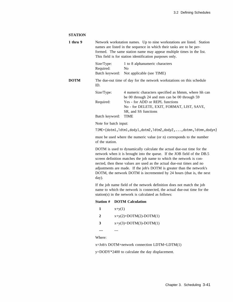
3.2 Defining Schedules
STATION
1 thru 9 Network workstation names. Up to nine workstations are listed. Stationnames are listed in the sequence in which their tasks are to be per-formed. The same station name may appear multiple times in the list.This field is for station identification purposes only.
Size/Type: 1 to 8 alphanumeric charactersRequired: NoBatch keyword: Not applicable (see TIME)
DOTM The due-out time of day for the network workstations on this scheduleID.
Size/Type: 4 numeric characters specified as hhmm, where hh canbe 00 through 24 and mm can be 00 through 59
Required: Yes - for ADD or REPL functionsNo - for DELETE, EXIT, FORMAT, LIST, SAVE,SR, and SS functions
Batch keyword: TIME
Note for batch input:
TIME=(dotm1,ldtm1,dody1,dotm2,ldtm2,dody2,...,dotmn,ldtmn,dodyn)
must be used where the numeric value (or n) corresponds to the numberof the station.
DOTM is used to dynamically calculate the actual due-out time for thenetwork when it is brought into the queue. If the JOB field of the DB.5screen definition matches the job name to which the network is con-nected, then these values are used as the actual due-out times and noadjustments are made. If the job's DOTM is greater than the network'sDOTM, the network DOTM is incremented by 24 hours (that is, the nextday).
If the job name field of the network definition does not match the jobname to which the network is connected, the actual due-out time for thestation(s) in the network is calculated as follows:
Station # DOTM Calculation
1 x+y(1)
2 x+y(2)+DOTM(2)-DOTM(1)
3 x+y(3)+DOTM(3)-DOTM(1)
--- ---
Where:
x=Job's DOTM+network connection LDTM+LDTM(1)
y=DODY*2400 to calculate the day displacement.
Chapter 3. Scheduling 3-41
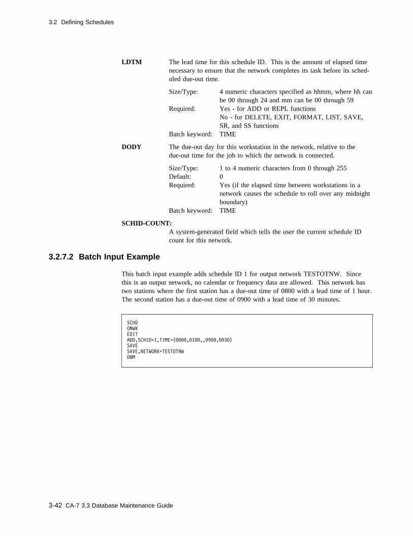
3.2 Defining Schedules
LDTM The lead time for this schedule ID. This is the amount of elapsed timenecessary to ensure that the network completes its task before its sched-uled due-out time.
Size/Type: 4 numeric characters specified as hhmm, where hh canbe 00 through 24 and mm can be 00 through 59
Required: Yes - for ADD or REPL functionsNo - for DELETE, EXIT, FORMAT, LIST, SAVE,SR, and SS functions
Batch keyword: TIME
DODY The due-out day for this workstation in the network, relative to thedue-out time for the job to which the network is connected.
Size/Type: 1 to 4 numeric characters from 0 through 255Default: 0Required: Yes (if the elapsed time between workstations in a
network causes the schedule to roll over any midnightboundary)
Batch keyword: TIME
SCHID-COUNT:A system-generated field which tells the user the current schedule IDcount for this network.
3.2.7.2 Batch Input Example
This batch input example adds schedule ID 1 for output network TESTOTNW. Sincethis is an output network, no calendar or frequency data are allowed. This network hastwo stations where the first station has a due-out time of 0800 with a lead time of 1 hour.The second station has a due-out time of 0900 with a lead time of 30 minutes.
SCHD
ONWK
EDIT
ADD,SCHID=1,TIME=(�8��,�1��,,�9��,��3�)
SAVE
SAVE,NETWORK=TESTOTNW
DBM
3-42 CA-7 3.3 Database Maintenance Guide

3.2 Defining Schedules
3.2.8 Trigger Scheduling Screens
The database elements which can trigger the scheduling of a job are jobs, data sets, andinput networks. The topics which follow identify the different types corresponding tothese elements, their keywords, and how they cause triggering.
All trigger commands share common field requirements. Required fields for all triggercommands (batch or online) are identified in 3.2.11.2, “Field Descriptions” on page 3-47.
Uniqueness of the trigger relationship is determined by the triggering element, triggeredjob name, and schedule ID. When a triggering element is successfully completed/created,the triggered job (TRGD-JOB) enters the request queue. The TRGD-JOB assumes theschedule ID of the triggering element unless TRGID is specified, in which case theschedule ID is replaced by TRGID.
Up to 255 job name/schedule ID combinations may be triggered per triggering element,or one job can be triggered by up to 255 elements.
Chapter 3. Scheduling 3-43

3.2 Defining Schedules
3.2.9 DB.2.4 - Job Triggering Screen
Use this screen to review or define jobs which trigger scheduling of other jobs when theysuccessfully complete.
� �
--------------------------- CA-7 JOB TRIGGERING ----------------------------
FUNCTION: xxxxxxxx (FORMAT,LIST,UPD) PAGE nnnn
JOB: xxxxxxxx
OPT SCHID TRGD-JOB TRGID DOTM QTM LDTM SBTM C---- EXCEPTIONS ----C
x nnn xxxxxxxx nnn hhmm mmmm hhmm hhmm xxxxxxxxxxxxxxxxxxxxxx
x nnn xxxxxxxx nnn hhmm mmmm hhmm hhmm xxxxxxxxxxxxxxxxxxxxxx
x nnn xxxxxxxx nnn hhmm mmmm hhmm hhmm xxxxxxxxxxxxxxxxxxxxxx
x nnn xxxxxxxx nnn hhmm mmmm hhmm hhmm xxxxxxxxxxxxxxxxxxxxxx
x nnn xxxxxxxx nnn hhmm mmmm hhmm hhmm xxxxxxxxxxxxxxxxxxxxxx
x nnn xxxxxxxx nnn hhmm mmmm hhmm hhmm xxxxxxxxxxxxxxxxxxxxxx
x nnn xxxxxxxx nnn hhmm mmmm hhmm hhmm xxxxxxxxxxxxxxxxxxxxxx
x nnn xxxxxxxx nnn hhmm mmmm hhmm hhmm xxxxxxxxxxxxxxxxxxxxxx
x nnn xxxxxxxx nnn hhmm mmmm hhmm hhmm xxxxxxxxxxxxxxxxxxxxxx
x nnn xxxxxxxx nnn hhmm mmmm hhmm hhmm xxxxxxxxxxxxxxxxxxxxxx
x nnn xxxxxxxx nnn hhmm mmmm hhmm hhmm xxxxxxxxxxxxxxxxxxxxxx
x nnn xxxxxxxx nnn hhmm mmmm hhmm hhmm xxxxxxxxxxxxxxxxxxxxxx
x nnn xxxxxxxx nnn hhmm mmmm hhmm hhmm xxxxxxxxxxxxxxxxxxxxxx
x nnn xxxxxxxx nnn hhmm mmmm hhmm hhmm xxxxxxxxxxxxxxxxxxxxxx
x nnn xxxxxxxx nnn hhmm mmmm hhmm hhmm xxxxxxxxxxxxxxxxxxxxxx
OPTIONS: A=ADD,D=DELETE,U=UPDATE,C=PROCESSED,?=ERROR
PROGRAM: SM75 MSG-INDX: nn -- DB.2.4 -- yy.ddd / hh:mm:ss
MESSAGE:
( )
To display, enter:
� 4 as the FUNCTION on the DB.2 Menu screen.� 2.4 as the FUNCTION on the DB Menu screen.� DB.2.4 as the FUNCTION on any other menu or formatted input screen.� DB.2.4 or SCHD,JTRG as a top line command.
To exit:
� Press the PF3 key to return to the DB.2 Menu screen except with the TSO/ISPFinterface when PF3 has been assigned to some other function.
� Move the cursor to the top line of the screen and enter the desired top line commandif yet another function is desired.
3.2.9.1 Usage Notes
Use the JOB field to define the triggering job.
See 3.2.11.2, “Field Descriptions” on page 3-47 for other keyword descriptions.
3-44 CA-7 3.3 Database Maintenance Guide

3.2 Defining Schedules
3.2.10 DB.2.5 - Input Network Triggering Screen
Use this screen to define or review input networks which trigger job scheduling whentheir last workstation is logged out.
� �
---------------------- CA-7 INPUT NETWORK TRIGGERING -----------------------
FUNCTION: xxxxxxxx (FORMAT,LIST,UPD) PAGE nnnn
NWK: xxxxxxxx DSNBR: nnnnnn
OPT SCHID TRGD-JOB TRGID DOTM QTM LDTM SBTM C---- EXCEPTIONS ----C
x nnn xxxxxxxx nnn hhmm mmmm hhmm hhmm xxxxxxxxxxxxxxxxxxxxxx
x nnn xxxxxxxx nnn hhmm mmmm hhmm hhmm xxxxxxxxxxxxxxxxxxxxxx
x nnn xxxxxxxx nnn hhmm mmmm hhmm hhmm xxxxxxxxxxxxxxxxxxxxxx
x nnn xxxxxxxx nnn hhmm mmmm hhmm hhmm xxxxxxxxxxxxxxxxxxxxxx
x nnn xxxxxxxx nnn hhmm mmmm hhmm hhmm xxxxxxxxxxxxxxxxxxxxxx
x nnn xxxxxxxx nnn hhmm mmmm hhmm hhmm xxxxxxxxxxxxxxxxxxxxxx
x nnn xxxxxxxx nnn hhmm mmmm hhmm hhmm xxxxxxxxxxxxxxxxxxxxxx
x nnn xxxxxxxx nnn hhmm mmmm hhmm hhmm xxxxxxxxxxxxxxxxxxxxxx
x nnn xxxxxxxx nnn hhmm mmmm hhmm hhmm xxxxxxxxxxxxxxxxxxxxxx
x nnn xxxxxxxx nnn hhmm mmmm hhmm hhmm xxxxxxxxxxxxxxxxxxxxxx
x nnn xxxxxxxx nnn hhmm mmmm hhmm hhmm xxxxxxxxxxxxxxxxxxxxxx
x nnn xxxxxxxx nnn hhmm mmmm hhmm hhmm xxxxxxxxxxxxxxxxxxxxxx
x nnn xxxxxxxx nnn hhmm mmmm hhmm hhmm xxxxxxxxxxxxxxxxxxxxxx
x nnn xxxxxxxx nnn hhmm mmmm hhmm hhmm xxxxxxxxxxxxxxxxxxxxxx
x nnn xxxxxxxx nnn hhmm mmmm hhmm hhmm xxxxxxxxxxxxxxxxxxxxxx
OPTIONS: A=ADD,D=DELETE,U=UPDATE,C=PROCESSED,?=ERROR
PROGRAM: SM75 MSG-INDX: nn -- DB.2.5 -- yy.ddd / hh:mm:ss
MESSAGE:
( )
To display, enter:
� 5 as the FUNCTION on the DB.2 Menu screen.� 2.5 as the FUNCTION on the DB Menu screen.� DB.2.5 as the FUNCTION on any other menu or formatted input screen.� DB.2.5 or SCHD,NTRG as a top line command.
To exit:
� Press the PF3 key to return to the DB.2 Menu screen except with the TSO/ISPFinterface when PF3 has been assigned to some other function.
� Move the cursor to the top line of the screen and enter the desired top line commandif yet another function is desired.
3.2.10.1 Usage Notes
Use the NWK and/or DSNBR keyword fields to define the triggering input network.
See 3.2.11.2, “Field Descriptions” on page 3-47 for other keyword descriptions.
Chapter 3. Scheduling 3-45

3.2 Defining Schedules
3.2.11 DB.2.6 - Data Set Triggering Screen
Use this screen to define or review data sets which trigger job scheduling when eithertheir creating jobs complete successfully or when the created/updated data set is closed.See also the POST AT CLOSE TIME field on the DB.6 screen and the 9.2.1.1, “FieldDescriptions” on page 9-6.
� �
------------------------- CA-7 DATA SET TRIGGERING -------------------------
FUNCTION: xxxxxxxx (FORMAT,LIST,UPD) PAGE nnnn
DSN: xxxxxxxxxxxxxxxxxxxxxxxxxxxxxxxxxxxxxxxxxxxx DSNBR: nnnnnn
OPT SCHID TRGD-JOB TRGID DOTM QTM LDTM SBTM C---- EXCEPTIONS ----C
x nnn xxxxxxxx nnn hhmm mmmm hhmm hhmm xxxxxxxxxxxxxxxxxxxxxx
x nnn xxxxxxxx nnn hhmm mmmm hhmm hhmm xxxxxxxxxxxxxxxxxxxxxx
x nnn xxxxxxxx nnn hhmm mmmm hhmm hhmm xxxxxxxxxxxxxxxxxxxxxx
x nnn xxxxxxxx nnn hhmm mmmm hhmm hhmm xxxxxxxxxxxxxxxxxxxxxx
x nnn xxxxxxxx nnn hhmm mmmm hhmm hhmm xxxxxxxxxxxxxxxxxxxxxx
x nnn xxxxxxxx nnn hhmm mmmm hhmm hhmm xxxxxxxxxxxxxxxxxxxxxx
x nnn xxxxxxxx nnn hhmm mmmm hhmm hhmm xxxxxxxxxxxxxxxxxxxxxx
x nnn xxxxxxxx nnn hhmm mmmm hhmm hhmm xxxxxxxxxxxxxxxxxxxxxx
x nnn xxxxxxxx nnn hhmm mmmm hhmm hhmm xxxxxxxxxxxxxxxxxxxxxx
x nnn xxxxxxxx nnn hhmm mmmm hhmm hhmm xxxxxxxxxxxxxxxxxxxxxx
x nnn xxxxxxxx nnn hhmm mmmm hhmm hhmm xxxxxxxxxxxxxxxxxxxxxx
x nnn xxxxxxxx nnn hhmm mmmm hhmm hhmm xxxxxxxxxxxxxxxxxxxxxx
x nnn xxxxxxxx nnn hhmm mmmm hhmm hhmm xxxxxxxxxxxxxxxxxxxxxx
x nnn xxxxxxxx nnn hhmm mmmm hhmm hhmm xxxxxxxxxxxxxxxxxxxxxx
x nnn xxxxxxxx nnn hhmm mmmm hhmm hhmm xxxxxxxxxxxxxxxxxxxxxx
OPTIONS: A=ADD,D=DELETE,U=UPDATE,C=PROCESSED,?=ERROR
PROGRAM: SM75 MSG-INDX: nn -- DB.2.6 -- yy.ddd / hh:mm:ss
MESSAGE:
( )
To display, enter:
� 6 as the FUNCTION on the DB.2 Menu screen.� 2.6 as the FUNCTION on the DB Menu screen.� DB.2.6 as the FUNCTION on any other menu or formatted input screen.� DB.2.6 or SCHD,DTRG as a top line command.
To exit:
� Press the PF3 key to return to the DB.2 Menu screen except with the TSO/ISPFinterface when PF3 has been assigned to some other function.
� Move the cursor to the top line of the screen and enter the desired top line commandif yet another function is desired.
3.2.11.1 Usage Notes
Use the DSN and/or DSNBR keywords to define the triggering data set.
See 3.2.11.2, “Field Descriptions” on page 3-47 for other keyword descriptions.
VSAM data sets and partitioned data sets (PDS) cannot be used as data set triggers.
3-46 CA-7 3.3 Database Maintenance Guide
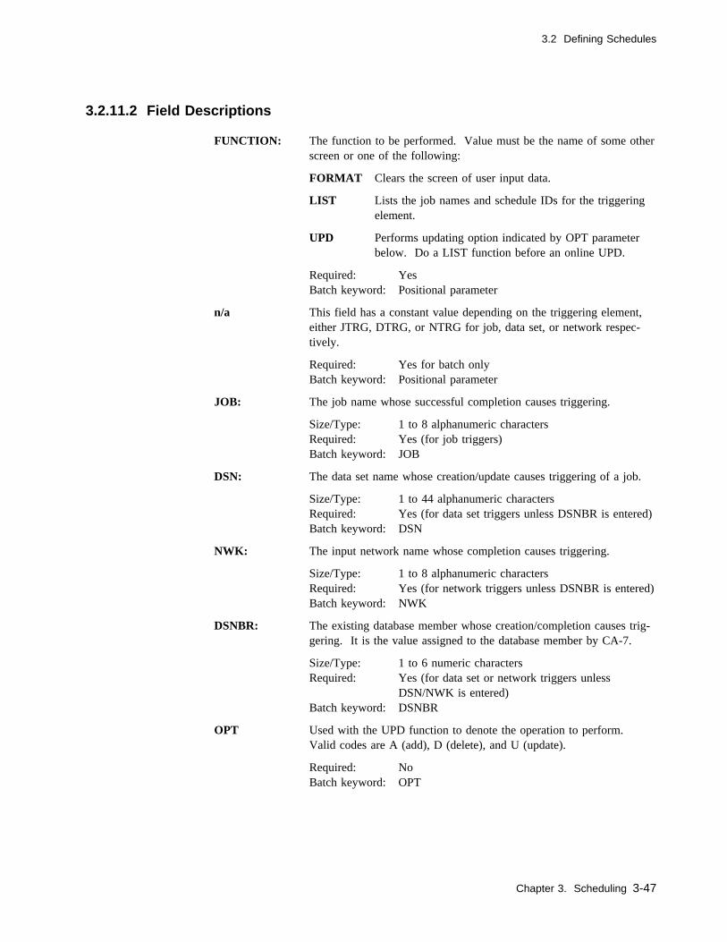
3.2 Defining Schedules
3.2.11.2 Field Descriptions
FUNCTION: The function to be performed. Value must be the name of some otherscreen or one of the following:
FORMAT Clears the screen of user input data.
LIST Lists the job names and schedule IDs for the triggeringelement.
UPD Performs updating option indicated by OPT parameterbelow. Do a LIST function before an online UPD.
Required: YesBatch keyword: Positional parameter
n/a This field has a constant value depending on the triggering element,either JTRG, DTRG, or NTRG for job, data set, or network respec-tively.
Required: Yes for batch onlyBatch keyword: Positional parameter
JOB: The job name whose successful completion causes triggering.
Size/Type: 1 to 8 alphanumeric charactersRequired: Yes (for job triggers)Batch keyword: JOB
DSN: The data set name whose creation/update causes triggering of a job.
Size/Type: 1 to 44 alphanumeric charactersRequired: Yes (for data set triggers unless DSNBR is entered)Batch keyword: DSN
NWK: The input network name whose completion causes triggering.
Size/Type: 1 to 8 alphanumeric charactersRequired: Yes (for network triggers unless DSNBR is entered)Batch keyword: NWK
DSNBR: The existing database member whose creation/completion causes trig-gering. It is the value assigned to the database member by CA-7.
Size/Type: 1 to 6 numeric charactersRequired: Yes (for data set or network triggers unless
DSN/NWK is entered)Batch keyword: DSNBR
OPT Used with the UPD function to denote the operation to perform.Valid codes are A (add), D (delete), and U (update).
Required: NoBatch keyword: OPT
Chapter 3. Scheduling 3-47
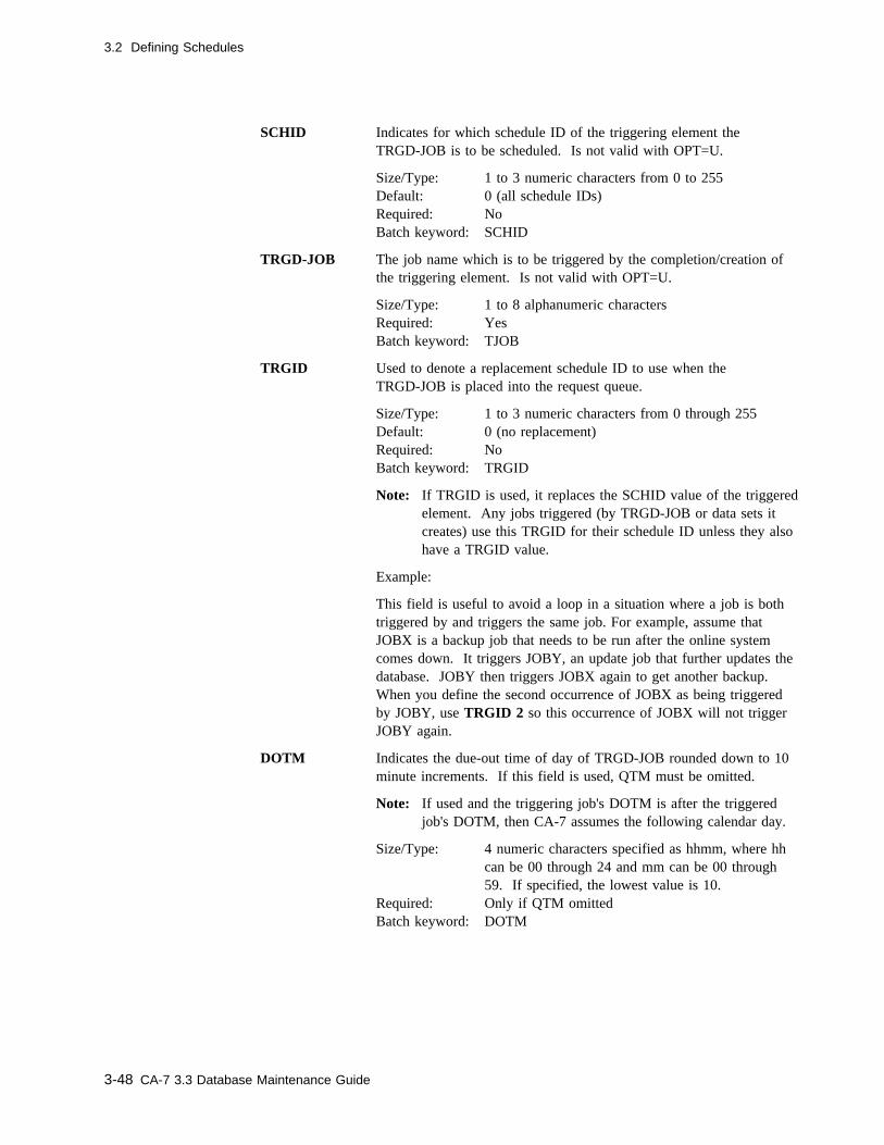
3.2 Defining Schedules
SCHID Indicates for which schedule ID of the triggering element theTRGD-JOB is to be scheduled. Is not valid with OPT=U.
Size/Type: 1 to 3 numeric characters from 0 to 255Default: 0 (all schedule IDs)Required: NoBatch keyword: SCHID
TRGD-JOB The job name which is to be triggered by the completion/creation ofthe triggering element. Is not valid with OPT=U.
Size/Type: 1 to 8 alphanumeric charactersRequired: YesBatch keyword: TJOB
TRGID Used to denote a replacement schedule ID to use when theTRGD-JOB is placed into the request queue.
Size/Type: 1 to 3 numeric characters from 0 through 255Default: 0 (no replacement)Required: NoBatch keyword: TRGID
Note: If TRGID is used, it replaces the SCHID value of the triggeredelement. Any jobs triggered (by TRGD-JOB or data sets itcreates) use this TRGID for their schedule ID unless they alsohave a TRGID value.
Example:
This field is useful to avoid a loop in a situation where a job is bothtriggered by and triggers the same job. For example, assume thatJOBX is a backup job that needs to be run after the online systemcomes down. It triggers JOBY, an update job that further updates thedatabase. JOBY then triggers JOBX again to get another backup.When you define the second occurrence of JOBX as being triggeredby JOBY, use TRGID 2 so this occurrence of JOBX will not triggerJOBY again.
DOTM Indicates the due-out time of day of TRGD-JOB rounded down to 10minute increments. If this field is used, QTM must be omitted.
Note: If used and the triggering job's DOTM is after the triggeredjob's DOTM, then CA-7 assumes the following calendar day.
Size/Type: 4 numeric characters specified as hhmm, where hhcan be 00 through 24 and mm can be 00 through59. If specified, the lowest value is 10.
Required: Only if QTM omittedBatch keyword: DOTM
3-48 CA-7 3.3 Database Maintenance Guide

3.2 Defining Schedules
QTM Indicates the elapsed queue time of TRGD-JOB rounded down to 10minute increments. If this field is used, DOTM must be omitted sincedue-out time is then calculated as deadline time plus runtime, wheredeadline time is calculated as current date/time plus queue time.
Note: Either DOTM or QTM must be used.
Size/Type: 4 numeric characters specified as hhmm, where hhcan be 00 through 24 and mm can be 00 through59, the highest value being 2400
Required: Only if DOTM omittedBatch keyword: QTM
LDTM Indicates the elapsed lead time for TRGD-JOB rounded to 10 minuteincrements. This field specifies the lead or processing time necessaryto ensure that TRGD-JOB meets its due-out time.
Size/Type: 4 numeric characters specified as hhmm, where hhcan be 00 through 24 and mm can be 00 through 59
Default 0000Required: NoBatch keyword: LEADTM
SBTM A field which imposes a submit time of day requirement onTRGD-JOB. When used, the job is not submitted before this time.SBTM is always rounded down to 15 minute increments.
Note: If QTM is used, the date for the submit time requirement willbe the same as the deadline start date. If DOTM is used andthe SBTM is less than the DOTM, the date for the SBTM isthe same as the deadline start date. Otherwise, the SBTM dateis the previous day.
Size/Type: 4 numeric characters specified as hhmm, where hhcan be 00 through 24 and mm can be 00 through 59
Default: 0 (no specific submit time requirement)Required: NoBatch keyword: SBTM
Chapter 3. Scheduling 3-49

3.2 Defining Schedules
EXCEPTIONS This is informational only. Brief messages appear here when anexception occurs trying to process the entry on this line.
Batch keyword: Not applicable
Messages which can appear and their meanings are as follows:
DOTM/QTM CONFLICTOnly one of these fields can be specified.
ERROR FROM: modulenameInternal logic error. Contact your installation's CA-7 spe-cialist for assistance.
INVALID VALUE: fieldnameThe value for the indicated field is not valid.
NO ROOM IN DATABASEThe CA-7 database is full. Contact your installation'sCA-7 specialist for assistance.
SCHID 0 ALREADY EXISTSTrigger is already defined for schedule ID zero whichapplies to all schedule IDs.
SECURITY EXCEPTIONYou are not authorized to access that job.
TOO HIGH FOR: fieldnameThe numeric value for the indicated field exceeds themaximum limit.
TOO LOW FOR: fieldnameThe numeric value does not meet a valid range.
TRGD-JOB ACCESS ERRORAn I/O error occurred while reading the triggered jobfrom the database.
TRGD-JOB NOT FOUNDThe triggered job is not defined in the database.
TRIGGER ALREADY EXISTSTrigger is already defined for this schedule ID.
WARNING: TRIGGER LOOPJob is triggering itself. This is only a warning, and thedatabase is updated.
3-50 CA-7 3.3 Database Maintenance Guide
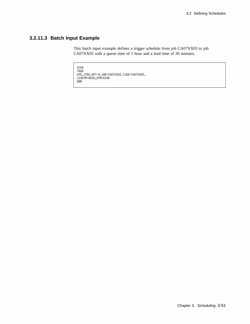
3.2 Defining Schedules
3.2.11.3 Batch Input Example
This batch input example defines a trigger schedule from job CA07XX03 to jobCA07XX05 with a queue time of 1 hour and a lead time of 30 minutes.
SCHD
TRGR
UPD,JTRG,OPT=A,JOB=CA�7XX�3,TJOB=CA�7XX�5,
LEADTM=��3�,QTM=�1��
DBM
Chapter 3. Scheduling 3-51

3.2 Defining Schedules
3.2.12 DB.2.7 - Modification to Resolved Schedule Dates Screen
This screen provides the user with a rapid and direct method of permanently altering theresolved schedule information for either a job or input network without having to totallyredefine the schedule. Such schedule modifications can be made any time after theschedule has been resolved and are effective immediately.
� �
--------------- CA-7 MODIFICATION TO RESOLVED SCHEDULE DATES ---------------
FUNCTION: xxxxxxxx (FORMAT,LIST,UPD)
JOB: xxxxxxxx NETWORK: xxxxxxxx MODSTAT: xxxxxxxx
SCHID: nnn YEAR: yyyy
1 1 2 2 3 3
....5....� ....5....� ....5....� 1
JAN nnnnnnnnnn nnnnnnnnnn nnnnnnnnnn n
FEB nnnnnnnnnn nnnnnnnnnn nnnnnnnnn
MAR nnnnnnnnnn nnnnnnnnnn nnnnnnnnnn n
APR nnnnnnnnnn nnnnnnnnnn nnnnnnnnnn
MAY nnnnnnnnnn nnnnnnnnnn nnnnnnnnnn n
JUN nnnnnnnnnn nnnnnnnnnn nnnnnnnnnn
JUL nnnnnnnnnn nnnnnnnnnn nnnnnnnnnn n
AUG nnnnnnnnnn nnnnnnnnnn nnnnnnnnnn n
SEP nnnnnnnnnn nnnnnnnnnn nnnnnnnnnn
OCT nnnnnnnnnn nnnnnnnnnn nnnnnnnnnn n
NOV nnnnnnnnnn nnnnnnnnnn nnnnnnnnnn
DEC nnnnnnnnnn nnnnnnnnnn nnnnnnnnnn n
PROGRAM: SM8� MSG-INDX: nn -- DB.2.7 -- yy.ddd / hh:mm:ss
MESSAGE:
( )
To display, enter:
� 7 as the FUNCTION on the DB.2 Menu screen.� 2.7 as the FUNCTION on the DB Menu screen.� DB.2.7 as the FUNCTION on any other menu or formatted input screen.� DB.2.7 or SCHDMOD as a top line command.
To exit:
� Press the PF3 key to return to the DB.2 Menu screen except with the TSO/ISPFinterface when PF3 has been assigned to some other function.
� Move the cursor to the top line of the screen and enter the desired top line commandif yet another function is desired.
3-52 CA-7 3.3 Database Maintenance Guide
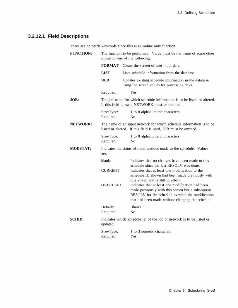
3.2 Defining Schedules
3.2.12.1 Field Descriptions
There are no batch keywords since this is an online only function.
FUNCTION: The function to be performed. Value must be the name of some otherscreen or one of the following:
FORMAT Clears the screen of user input data.
LIST Lists schedule information from the database.
UPD Updates existing schedule information in the databaseusing the screen values for processing days.
Required: Yes
JOB: The job name for which schedule information is to be listed or altered.If this field is used, NETWORK must be omitted.
Size/Type: 1 to 8 alphanumeric charactersRequired: No
NETWORK: The name of an input network for which schedule information is to belisted or altered. If this field is used, JOB must be omitted.
Size/Type: 1 to 8 alphanumeric charactersRequired: No
MODSTAT: Indicates the status of modifications made to the schedule. Valuesare:
blanks Indicates that no changes have been made to thisschedule since the last RESOLV was done.
CURRENT Indicates that at least one modification to theschedule ID shown had been made previously withthis screen and is still in effect.
OVERLAID Indicates that at least one modification had beenmade previously with this screen but a subsequentRESOLV for the schedule overlaid the modificationthat had been made without changing the schedule.
Default: BlanksRequired: No
SCHID: Indicates which schedule ID of the job or network is to be listed orupdated.
Size/Type: 1 to 3 numeric charactersRequired: Yes
Chapter 3. Scheduling 3-53
3.2 Defining Schedules
YEAR: Indicates the calendar year for the first month of the schedule dis-played.
JAN thru DEC These values indicate the run and nonrun Julian days of the job ornetwork for the month indicated. Any scheduled day (1) may bechanged to a nonscheduled day (0), or vice versa, with the UPD func-tion. This can be easily accomplished with a LIST followed by aUPD. Schedule Resolution negates these changes.
1 Days on which work is done, a scheduled day.
0 Days on which work is not done, a nonscheduled day.
Note: If the schedule ID being reviewed was resolved on a Julythrough June basis instead of a January through Decemberbasis, the month titles show JUL through DEC followed byJAN through JUN.
Required: No
3.2.12.2 Usage Notes
Unlike other DB functions, DB.2.7 is only available as an online function.
Once displayed, you may change the values as necessary to accomplish the desiredchanges.
Note: If schedule scan has already brought the job into the queue and the schedule hasbeen adjusted for the day, then the DB.2.7 changes do not take effect for that day.
3-54 CA-7 3.3 Database Maintenance Guide
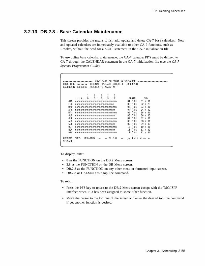
3.2 Defining Schedules
3.2.13 DB.2.8 - Base Calendar Maintenance
This screen provides the means to list, add, update and delete CA-7 base calendars. Newand updated calendars are immediately available to other CA-7 functions, such asResolve, without the need for a SCAL statement in the CA-7 initialization file.
To use online base calendar maintenance, the CA-7 calendar PDS must be defined toCA-7 through the CALENDAR statement in the CA-7 initialization file (see the CA-7Systems Programmer Guide).
� �
---------------------- CA-7 BASE CALENDAR MAINTENANCE ----------------------
FUNCTION: xxxxxxxx (FORMAT,LIST,ADD,UPD,DELETE,REFRESH)
CALENDAR: xxxxxxxx SCHONLY: x YEAR: nn
1 1 2 2 3
....5....�....5....�....5....�1 BEGIN END
JAN nnnnnnnnnnnnnnnnnnnnnnnnnnnnnnn �1 / �1 �1 / 31
FEB nnnnnnnnnnnnnnnnnnnnnnnnnnnnn �2 / �1 �2 / 28
MAR nnnnnnnnnnnnnnnnnnnnnnnnnnnnnnn �3 / �1 �3 / 31
APR nnnnnnnnnnnnnnnnnnnnnnnnnnnnnn �4 / �1 �4 / 3�
MAY nnnnnnnnnnnnnnnnnnnnnnnnnnnnnnn �5 / �1 �5 / 31
JUN nnnnnnnnnnnnnnnnnnnnnnnnnnnnnn �6 / �1 �6 / 3�
JUL nnnnnnnnnnnnnnnnnnnnnnnnnnnnnnn �7 / �1 �7 / 31
AUG nnnnnnnnnnnnnnnnnnnnnnnnnnnnnnn �8 / �1 �8 / 31
SEP nnnnnnnnnnnnnnnnnnnnnnnnnnnnnn �9 / �1 �9 / 3�
OCT nnnnnnnnnnnnnnnnnnnnnnnnnnnnnnn 1� / �1 1� / 31
NOV nnnnnnnnnnnnnnnnnnnnnnnnnnnnnn 11 / �1 11 / 3�
DEC nnnnnnnnnnnnnnnnnnnnnnnnnnnnnnn 12 / �1 12 / 31
PROGRAM: SM85 MSG-INDX: nn -- DB.2.8 -- yy.ddd / hh:mm:ss
MESSAGE:
( )
To display, enter:
� 8 as the FUNCTION on the DB.2 Menu screen.� 2.8 as the FUNCTION on the DB Menu screen.� DB.2.8 as the FUNCTION on any other menu or formatted input screen.� DB.2.8 or CALMOD as a top line command.
To exit:
� Press the PF3 key to return to the DB.2 Menu screen except with the TSO/ISPFinterface when PF3 has been assigned to some other function.
� Move the cursor to the top line of the screen and enter the desired top line commandif yet another function is desired.
Chapter 3. Scheduling 3-55

3.2 Defining Schedules
3.2.13.1 Field Descriptions
There are no batch keywords since this is an online only function.
FUNCTION: The function to be performed. Value must be the name of some otherscreen or one of the following:
FORMAT Clears the screen of user input data.
LIST Lists data for the calendar specified in the CALENDARfield.
ADD Adds the calendar displayed. The YEAR field must bespecified to add a new calendar.
UPD Updates the calendar displayed. Any changes made tothe calendar take effect immediately. That is, if youupdate a calendar and then do a RESOLVe against a jobusing that calendar, the updated version of the calendarwill be used.
DELETE Deletes the calendar specified in the CALENDAR field.The copy of the calendar saved in the CA-7 calendarPDS is deleted. The delete function has no effect on cal-endars which reside in load libraries.
REFRESH Fetches the load module copy of the calendar specifiedin the CALENDAR field and uses it to replace the copyin the CA-7 calendar PDS.
Required: Yes
CALENDAR: Name of the CA-7 calendar you wish to act on. For a calendar to beused by CA-7 to resolve job/network schedules the name must be inthe format SCALyyxx; where, yy is the last 2 digits of the year itrepresents and xx is a two-position suffix to uniquely identify the cal-endar. All calendar names that begin with SCAL must adhere to thisformat. However, you may create and save calendars under othernames to use as models or templates for the creation of other calen-dars.
Size/Type: 1 to 8 alphanumeric charactersRequired: Yes
3-56 CA-7 3.3 Database Maintenance Guide

3.2 Defining Schedules
SCHONLY: If Y (yes) is specified, then CA-7 will count only available processingdays when resolving a schedule with number of days relative to thebeginning or end of the month (see RDAY field on the 3.2.2, “DB.2.1- CPU Job Scheduling Screen” on page 3-11). If SCHONLY is set toN (no), CA-7 will count all days when calculating days relative to thebeginning or end of the month.
Default: N (NO)Required: No
YEAR: Specifies the year that the calendar represents. When using thestandard CA-7 calendar naming convention (SCALyyxx), the YEARshould match positions 5 and 6 of the calendar name.
Calendars can be defined for the twentieth or twenty-first centuries.Years 75 through 99 are considered to be part of the twentieth century(that is, 98 will be interpreted as 1998). Years 00 through 74 areconsidered to be part of the twenty-first century (that is, 02 will beinterpreted as 2002).
Size/Type: 2 numeric charactersRequired: Yes - for ADD or UPD functions if the calendar
name is not in standard SCALyyxx format
DAYS OF THE MONTH:Each month is represented by a string of zeros and ones. Each digitrepresents a particular day of that month. If the digit for a day is 1(one), it indicates that it is a 'processing day'. If the digit is 0 (zero),it indicates that it is not a processing day. The number of digits in anindividual string should represent the number of days in that calendarmonth.
Required: Yes - for ADD or UPD functions
BEGIN and END:For each month you may specify the beginning and ending days ofthat month. It must be used if the calendar being defined has non-standard months; for example, a fiscal or accounting calendar. Ayear-end boundary may only be crossed in the first or twelfth month.
Required: Yes - for ADD or UPD functions
Chapter 3. Scheduling 3-57
3.2 Defining Schedules
3.2.13.2 Usage Notes
1. Unlike other DB functions, DB.2.8 is only available as an online function.
2. To use online base calendar maintenance the CA-7 calendar PDS must be defined toCA-7 through the CALENDAR statement in the CA-7 initialization file (see the CA-7Systems Programmer Guide).
3. Base calendars will be automatically added to the CA-7 calendar PDS when:
a. A CALBLK statement is included in the CA-7 initialization file and the loadmodule copy exists but there is no copy in the PDS.
b. A reference is made to the calendar from the online base calendar maintenancefacility or with a RESOLVe or PRINT topline command and the load modulecopy exists but there is no copy in the PDS.
c. An ADD function is performed from the online base calendar maintenancefacility.
4. If you have assembled and link edited a new copy of a calendar and want to propa-gate it to the CA-7 calendar PDS, use the REFRESH function. This will replace theexisting copy in the CA-7 calendar PDS with a new converted copy of the loadlibrary version.
5. Base calendars which reside in the CA-7 calendar PDS do not require a CALBLKstatement in the CA-7 initialization file.
6. Calendars with nonstandard names can be created using the online base calendarmaintenance facility and used as patterns or models to create standard base calendars.All calendars stored in the CA-7 calendar PDS must have valid PDS member names(1-8 characters starting with an alpha or national character).
7. The DELETE function removes the specified calendar from the CA-7 calendar PDSONLY. It has no effect on a load module copy of the same calendar.
8. To list all calendar names in the CA-7 calendar PDS, issue the following toplinecommand:
LISTDIR,DSN=CSCALC
3-58 CA-7 3.3 Database Maintenance Guide

Chapter 4. Requirement Definitions
This chapter describes how CA-7 determines requirements from JCL, how to define andmaintain job requirements, and how requirements are satisfied.
Chapter 4. Requirement Definitions 4-1
4.1 Execution Requirements and the LOAD Process
4.1 Execution Requirements and the LOAD Process
4.1.1 Dependence Definition
As work is defined in the CA-7 database, dependencies (preexecution or predecessorrequirements) can be established so that work is not initiated until these dependencies aresatisfied.
Any job under the control of CA-7 can have predecessor requirements. CA-7 does notsubmit the job until all requirements are satisfied even though time scheduling criteria hasbeen met.
The main categories of predecessor requirements are as follows:
� Successful completion of predecessor jobs� Availability of data sets
� Date/time window� Completion of an input network� Mutual exclusivity with other jobs� Specified manual activities such as JCL overrides and manual verifications� Presence of other jobs in the CA-7 queues
Note: Jobs should not have more than 255 requirements.
4.1.2 Database Definitions
This chapter discusses predecessor requirement database definitions for CPU job, inputnetwork, user requirement, and data set predecessors.
It also discusses how to define those output networks which must be invoked uponnormal completion of a job and how to define report IDs which may be produced by ajob.
4-2 CA-7 3.3 Database Maintenance Guide

4.1 Execution Requirements and the LOAD Process
4.1.3 Data Set Dependencies
The LOAD process addresses the requirements associated with data set availability.Based on JCL, the LOAD process determines if the job being LOADed uses or creates aparticular data set and updates the database accordingly. Data set dependencies are estab-lished for the job for each data set that is input to the job. Unless the dependent job ismarked as a MAINT job on the DB.1 screen, it does not run before any required data setis created.
Whenever there is a permanent change to the JCL, the job must go back through theLOAD process which redefines the data set requirements for the job. LOAD is automaticif the JCL is changed through the DB.7 screen.
The LOAD process neither determines nor changes requirements except those associatedwith data set availability. If the job has requirements other than those associated withdata set availability that change, they must be specified through the various DB.3 screenfunctions. The LOAD process does not delete any requirements that were manuallyupdated or added through a DB.3 screen. This means that data set name changes requireDB.3 updates to delete outdated references unless RENAME was used on the DB.6screen before LOAD occurred.
4.1.4 Other Dependencies
The DB.1 screen contains fields such as HOLD, VERIFY, and JCL-OVRD with whichsome predecessor requirements can be permanently defined for a job. Top line com-mands HOLD, VERIFY, JCLOVRD, and ADDRQ are available for dynamically definingpredecessor requirements on a temporary basis. The QM.1 screen allows for dynamicallyadding some of these same predecessor requirements to jobs on a temporary basis.
A job's JCL can also include, on a scheduled basis if desired, commands to cause someof the same predecessor requirements to be applied to the job when the job is scheduledinto the queues. This is accomplished with a special set of commands known as Sched-uled Overrides which are discussed further on 10.2, “Scheduled Overrides” on page 10-6.Based on how these are scheduled, they may be permanent or temporary without havingbeen defined to the database.
Chapter 4. Requirement Definitions 4-3
4.1 Execution Requirements and the LOAD Process
4.1.5 Temporary Predecessors
Predecessor requirements are normally defined on a permanent basis. However, on occa-sion it may become necessary on a onetime basis to temporarily add new ones or skipexisting ones.
The DB.3 screens provide the ability to do that with the NEXT-RUN facility. Any suchonetime definitions are automatically deleted from the database after a single execution ofthe dependent job.
A job executing with any such temporary predecessors, either added or skipped, is identi-fied on LQ job inquiry output as executing with "temporary requirements."LJOB,LIST=RQMT, and so forth, also flag individual predecessors as SKIP or ONLY toindicate when these settings exist. QM.2 update screens reflect the letter O to identify aNEXT-RUN=ONLY predecessor while the letter A identifies one added through theADDRQ top line command. NEXT-RUN=SKIP predecessors do not appear on the QM.2update screens as they are skipped when the job enters the queue.
4-4 CA-7 3.3 Database Maintenance Guide
4.2 Satisfying Requirements
4.2 Satisfying Requirements
The system examines all of a job's defined predecessor requirements each time the job isscheduled. It itemizes these requirements and establishes a total count of the unsatisfiedrequirements for the job when it enters the request queue. As each unsatisfied require-ment is fulfilled, the count of the unsatisfied requirements is decremented. This count isknown as the master count and appears on many screens as MCNT. When the countreaches zero, the job moves to the ready queue and then is available for execution.
Outstanding requirements can be satisfied either manually or automatically. The require-ments automatically tracked and satisfied by the system are as follows:
� Successful job completion of a predecessor job under CA-7's control
� Input network completion of a network connection
When the last workstation in an input network is logged complete by the workstationoperator, CA-7 posts this network requirement as complete for any dependent jobs.
� Data set availability posting by:
– SMF feedback– Batch card load program (BLCP)
– Trailer step – U7SVC
� System date/time specifications
Most outstanding requirements needing manual intervention are related to:
� user requirements� manually prepared overrides
� manual verifications � restart requirements � hold requirements
These requirements must be posted by the POST command, QM.1 type screens, or othertop line commands such as:
SUBTM
VERIFY
The QM.2 screen can be used to view the requirements of a job in the request queue.The user can see both the outstanding and satisfied requirements for a job. The user canalso post and unpost requirements for a job by using this screen.
If requirements for a job are predictable, they may lend themselves to use of specialtrailer step job steps. See Chapter 2 of the CA-7 Interfaces Guide.
Chapter 4. Requirement Definitions 4-5
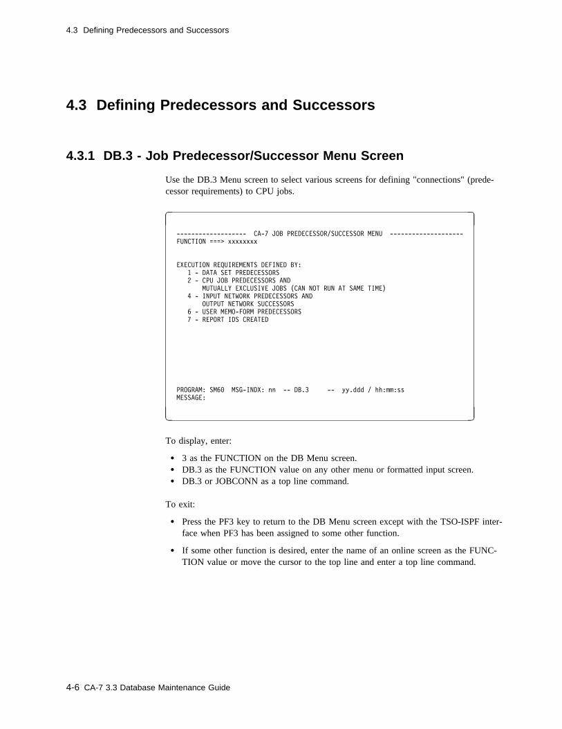
4.3 Defining Predecessors and Successors
4.3 Defining Predecessors and Successors
4.3.1 DB.3 - Job Predecessor/Successor Menu Screen
Use the DB.3 Menu screen to select various screens for defining "connections" (prede-cessor requirements) to CPU jobs.
� �
------------------- CA-7 JOB PREDECESSOR/SUCCESSOR MENU --------------------
FUNCTION ===> xxxxxxxx
EXECUTION REQUIREMENTS DEFINED BY:
1 - DATA SET PREDECESSORS
2 - CPU JOB PREDECESSORS AND
MUTUALLY EXCLUSIVE JOBS (CAN NOT RUN AT SAME TIME)
4 - INPUT NETWORK PREDECESSORS AND
OUTPUT NETWORK SUCCESSORS
6 - USER MEMO-FORM PREDECESSORS
7 - REPORT IDS CREATED
PROGRAM: SM6� MSG-INDX: nn -- DB.3 -- yy.ddd / hh:mm:ss
MESSAGE:
( )
To display, enter:
� 3 as the FUNCTION on the DB Menu screen.� DB.3 as the FUNCTION value on any other menu or formatted input screen.� DB.3 or JOBCONN as a top line command.
To exit:
� Press the PF3 key to return to the DB Menu screen except with the TSO-ISPF inter-face when PF3 has been assigned to some other function.
� If some other function is desired, enter the name of an online screen as the FUNC-TION value or move the cursor to the top line and enter a top line command.
4-6 CA-7 3.3 Database Maintenance Guide

4.3 Defining Predecessors and Successors
4.3.1.1 Usage Notes
Select the desired function by entering the appropriate FUNCTION value and pressing theEnter key.
Chapter 4. Requirement Definitions 4-7
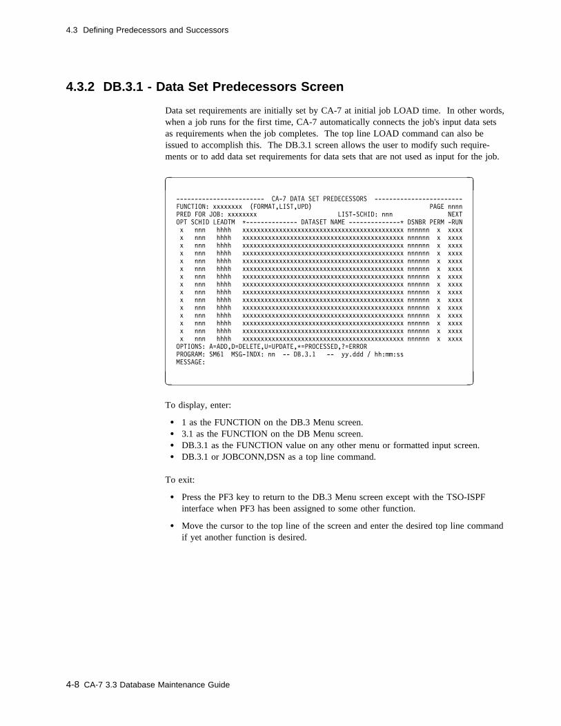
4.3 Defining Predecessors and Successors
4.3.2 DB.3.1 - Data Set Predecessors Screen
Data set requirements are initially set by CA-7 at initial job LOAD time. In other words,when a job runs for the first time, CA-7 automatically connects the job's input data setsas requirements when the job completes. The top line LOAD command can also beissued to accomplish this. The DB.3.1 screen allows the user to modify such require-ments or to add data set requirements for data sets that are not used as input for the job.
� �
------------------------ CA-7 DATA SET PREDECESSORS ------------------------
FUNCTION: xxxxxxxx (FORMAT,LIST,UPD) PAGE nnnn
PRED FOR JOB: xxxxxxxx LIST-SCHID: nnn NEXT
OPT SCHID LEADTM C-------------- DATASET NAME --------------C DSNBR PERM -RUN
x nnn hhhh xxxxxxxxxxxxxxxxxxxxxxxxxxxxxxxxxxxxxxxxxxxx nnnnnn x xxxx
x nnn hhhh xxxxxxxxxxxxxxxxxxxxxxxxxxxxxxxxxxxxxxxxxxxx nnnnnn x xxxx
x nnn hhhh xxxxxxxxxxxxxxxxxxxxxxxxxxxxxxxxxxxxxxxxxxxx nnnnnn x xxxx
x nnn hhhh xxxxxxxxxxxxxxxxxxxxxxxxxxxxxxxxxxxxxxxxxxxx nnnnnn x xxxx
x nnn hhhh xxxxxxxxxxxxxxxxxxxxxxxxxxxxxxxxxxxxxxxxxxxx nnnnnn x xxxx
x nnn hhhh xxxxxxxxxxxxxxxxxxxxxxxxxxxxxxxxxxxxxxxxxxxx nnnnnn x xxxx
x nnn hhhh xxxxxxxxxxxxxxxxxxxxxxxxxxxxxxxxxxxxxxxxxxxx nnnnnn x xxxx
x nnn hhhh xxxxxxxxxxxxxxxxxxxxxxxxxxxxxxxxxxxxxxxxxxxx nnnnnn x xxxx
x nnn hhhh xxxxxxxxxxxxxxxxxxxxxxxxxxxxxxxxxxxxxxxxxxxx nnnnnn x xxxx
x nnn hhhh xxxxxxxxxxxxxxxxxxxxxxxxxxxxxxxxxxxxxxxxxxxx nnnnnn x xxxx
x nnn hhhh xxxxxxxxxxxxxxxxxxxxxxxxxxxxxxxxxxxxxxxxxxxx nnnnnn x xxxx
x nnn hhhh xxxxxxxxxxxxxxxxxxxxxxxxxxxxxxxxxxxxxxxxxxxx nnnnnn x xxxx
x nnn hhhh xxxxxxxxxxxxxxxxxxxxxxxxxxxxxxxxxxxxxxxxxxxx nnnnnn x xxxx
x nnn hhhh xxxxxxxxxxxxxxxxxxxxxxxxxxxxxxxxxxxxxxxxxxxx nnnnnn x xxxx
x nnn hhhh xxxxxxxxxxxxxxxxxxxxxxxxxxxxxxxxxxxxxxxxxxxx nnnnnn x xxxx
OPTIONS: A=ADD,D=DELETE,U=UPDATE,C=PROCESSED,?=ERROR
PROGRAM: SM61 MSG-INDX: nn -- DB.3.1 -- yy.ddd / hh:mm:ss
MESSAGE:
( )
To display, enter:
� 1 as the FUNCTION on the DB.3 Menu screen.� 3.1 as the FUNCTION on the DB Menu screen.� DB.3.1 as the FUNCTION value on any other menu or formatted input screen.� DB.3.1 or JOBCONN,DSN as a top line command.
To exit:
� Press the PF3 key to return to the DB.3 Menu screen except with the TSO-ISPFinterface when PF3 has been assigned to some other function.
� Move the cursor to the top line of the screen and enter the desired top line commandif yet another function is desired.
4-8 CA-7 3.3 Database Maintenance Guide
4.3 Defining Predecessors and Successors
4.3.2.1 Field Descriptions
FUNCTION: The function to be performed. Value must be the name of someother screen or one of the following:
FORMAT Clears the screen of user input data.
LIST Lists data from the database. In batch, a formattedscreen is not listed; only a found or not found messageis returned.
UPD Updates a data set requirement according to OPT fieldvalues.
Required: YesBatch keyword: Positional parameter
n/a Predecessor type. Has a constant value of DSN for data sets.
Required: Yes for batch onlyBatch keyword: Positional parameter
PRED FOR JOB: The required job name for which data set predecessors are beingdefined.
Size/Type: 1 to 8 alphanumeric charactersRequired: YesBatch keyword: Positional parameter
LIST-SCHID: Applies only to the LIST function. When used, all connections forthe SCHID entered and all connections for schedule ID of 0 arelisted. Schedule IDs on each detail line apply to that line only.
Size/Type: 1 to 3 numeric charactersDefault: Null (Causes connections for all schedule IDs to
be listed)Required: NoBatch keyword: Not applicable
OPT This field is used with the UPD function to denote the type of con-nection operation. The operation codes are A (add), D (delete), andU (update).
Note: The U option applies only to LEADTM, PERM, andNEXT-RUN fields.
Required: NoBatch keyword: OPT
Chapter 4. Requirement Definitions 4-9

4.3 Defining Predecessors and Successors
SCHID Indicates for which schedule ID of this job the data set requirementis applied. The user cannot specify the zero default for one con-nection and use a nonzero schedule ID for another connection to thesame job and data set. An attempt to make such a connection resultsin an error message issued by CA-7. (For an online LIST function,the SCHID field on the same line as JOB field defaults to null,causing all schedule IDs to be listed.) This field is not valid withOPT=U.
Size/Type: 1 to 3 numeric characters from 0 through 255Default: 0 (requirement holds for all schedule IDs)Required: NoBatch keyword: SCHID
LEADTM Represents satisfaction lead time in hours. If nonzero, this valueoverrides any satisfaction lead time indicated on the DB.1 screen fordata sets. Values are:
0 The data set must have been created or updated since the starttime of the last run of the job. There is no special consider-ation for the amount of time which may have elapsed.
99 The requirement is never considered initially satisfied when thejob enters the request queue. The data set must be created orupdated while this job is in the request queue.
nn The data set must have been created or updated within the lastnn hours. Values for nn may be 1 to 98.
Default: 0Required: NoBatch keyword: LEADTM
DATASET NAMEThe fully qualified data set name which is to be defined as a data setrequirement for the job in the JOB field. Is not valid with OPT=U.
Size/Type: 1 to 44 alphanumeric charactersRequired: Yes (unless DSNBR is used)Batch keyword: DSN
4-10 CA-7 3.3 Database Maintenance Guide

4.3 Defining Predecessors and Successors
DSNBR The data set number (as previously assigned by CA-7) which is to bedefined as a data set requirement for the job in the JOB field. Is notvalid with OPT=U.
Size/Type: 1 to 6 numeric charactersRequired: Yes (unless DSNAME is used)Batch keyword: DSNBR
PERM Indicates whether this data set is to be considered permanent byCA-7 for this job's requirements (Y or N). The DB.6 screen may beused to mark a data set as permanent for all jobs. This field definesthe data set as permanent only for this job.
Default: NRequired: NoBatch keyword: PERM
NEXT-RUN Indicates status of this predecessor for the next run of this job. Thenext time the job is scheduled into the queues, the predecessors forthat execution are determined by this value.
YES Indicates normal, recurring predecessor.
ONLY Indicates onetime predecessor for only the next run ofthis job. Automatically discarded by CA-7 when nextsuccessful job completion is done. (See note.) Onlyvalid when OPT=A. Noted on QM.2 display as O andon various general inquiry displays as ONLY.
SKIP Indicates normal, recurring predecessor which is to beskipped (ignored) when the next run is scheduled intothe queues. Only valid when OPT=U and previous valuewas YES. Automatically reinstated to YES when nextsuccessful job completion is done. (See note.) Noted oncertain displays as SKIP but does not appear on QM.2displays since it is skipped when the job enters thequeues.
Default: Yes (for OPT value of A)Required: NoBatch keyword: NEXTRUN
Note: The "next successful job completion" only applies to jobsthat are not already in the queue when the NEXT-RUN is set.However, if the job is already in the queue and entered thequeue when the NEXT-RUN was SKIP or ONLY, then it isreset as indicated.
Chapter 4. Requirement Definitions 4-11
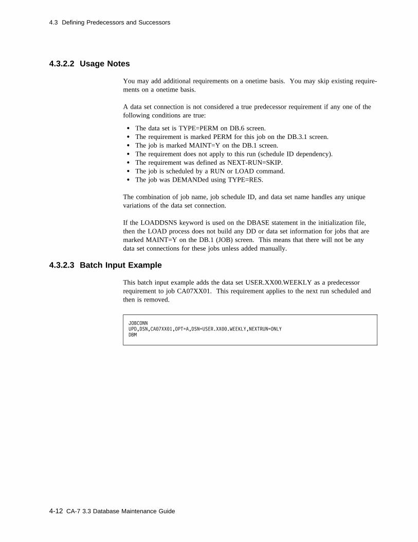
4.3 Defining Predecessors and Successors
4.3.2.2 Usage Notes
You may add additional requirements on a onetime basis. You may skip existing require-ments on a onetime basis.
A data set connection is not considered a true predecessor requirement if any one of thefollowing conditions are true:
� The data set is TYPE=PERM on DB.6 screen.� The requirement is marked PERM for this job on the DB.3.1 screen.� The job is marked MAINT=Y on the DB.1 screen.� The requirement does not apply to this run (schedule ID dependency).� The requirement was defined as NEXT-RUN=SKIP.� The job is scheduled by a RUN or LOAD command.� The job was DEMANDed using TYPE=RES.
The combination of job name, job schedule ID, and data set name handles any uniquevariations of the data set connection.
If the LOADDSNS keyword is used on the DBASE statement in the initialization file,then the LOAD process does not build any DD or data set information for jobs that aremarked MAINT=Y on the DB.1 (JOB) screen. This means that there will not be anydata set connections for these jobs unless added manually.
4.3.2.3 Batch Input Example
This batch input example adds the data set USER.XX00.WEEKLY as a predecessorrequirement to job CA07XX01. This requirement applies to the next run scheduled andthen is removed.
JOBCONN
UPD,DSN,CA�7XX�1,OPT=A,DSN=USER.XX��.WEEKLY,NEXTRUN=ONLY
DBM
4-12 CA-7 3.3 Database Maintenance Guide
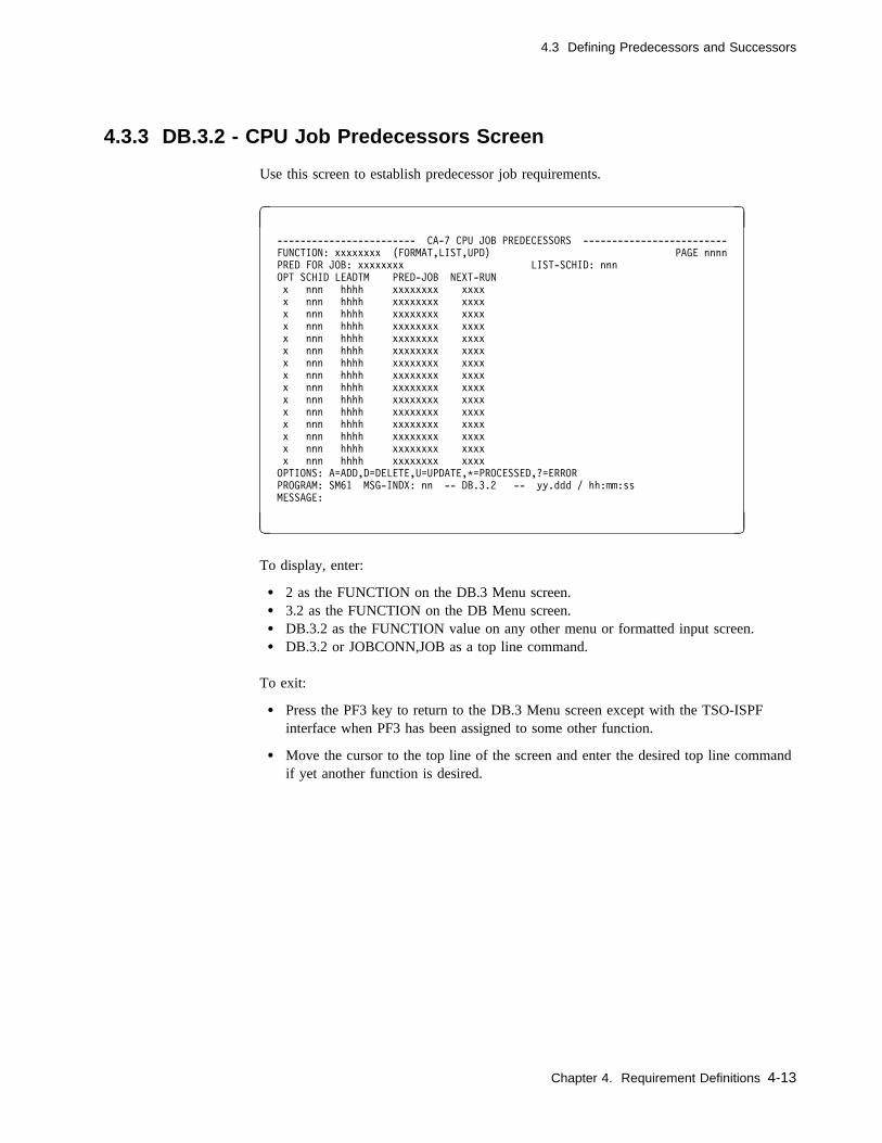
4.3 Defining Predecessors and Successors
4.3.3 DB.3.2 - CPU Job Predecessors Screen
Use this screen to establish predecessor job requirements.
� �
------------------------ CA-7 CPU JOB PREDECESSORS -------------------------
FUNCTION: xxxxxxxx (FORMAT,LIST,UPD) PAGE nnnn
PRED FOR JOB: xxxxxxxx LIST-SCHID: nnn
OPT SCHID LEADTM PRED-JOB NEXT-RUN
x nnn hhhh xxxxxxxx xxxx
x nnn hhhh xxxxxxxx xxxx
x nnn hhhh xxxxxxxx xxxx
x nnn hhhh xxxxxxxx xxxx
x nnn hhhh xxxxxxxx xxxx
x nnn hhhh xxxxxxxx xxxx
x nnn hhhh xxxxxxxx xxxx
x nnn hhhh xxxxxxxx xxxx
x nnn hhhh xxxxxxxx xxxx
x nnn hhhh xxxxxxxx xxxx
x nnn hhhh xxxxxxxx xxxx
x nnn hhhh xxxxxxxx xxxx
x nnn hhhh xxxxxxxx xxxx
x nnn hhhh xxxxxxxx xxxx
x nnn hhhh xxxxxxxx xxxx
OPTIONS: A=ADD,D=DELETE,U=UPDATE,C=PROCESSED,?=ERROR
PROGRAM: SM61 MSG-INDX: nn -- DB.3.2 -- yy.ddd / hh:mm:ss
MESSAGE:
( )
To display, enter:
� 2 as the FUNCTION on the DB.3 Menu screen.� 3.2 as the FUNCTION on the DB Menu screen.� DB.3.2 as the FUNCTION value on any other menu or formatted input screen.� DB.3.2 or JOBCONN,JOB as a top line command.
To exit:
� Press the PF3 key to return to the DB.3 Menu screen except with the TSO-ISPFinterface when PF3 has been assigned to some other function.
� Move the cursor to the top line of the screen and enter the desired top line commandif yet another function is desired.
Chapter 4. Requirement Definitions 4-13
4.3 Defining Predecessors and Successors
4.3.3.1 Field Descriptions
FUNCTION: The function to be performed. The value must be the name ofsome other screen or one of the following:
FORMAT Clears the screen of user input data.
LIST Lists data from the database. In batch, a formattedscreen is not listed; only a found or not found messageis returned.
UPD Updates predecessor job requirements in the databaseaccording to OPT field values.
Required: YesBatch keyword: Positional parameter
n/a Predecessor type. Has a constant value of JOB for jobs.
Required: Yes for batch onlyBatch keyword: Positional parameter
PRED FOR JOB: The job name for which job requirements are being defined orlisted.
Size/Type: 1 to 8 alphanumeric charactersRequired: YesBatch keyword: Positional parameter
LIST-SCHID Applies only to the LIST function. A SCHID of 0 applies to con-nections for all schedules and therefore is listed with connectionsfor any schedule ID requested. Schedule IDs on each detail lineapply to that line only.
Size/Type: 1 to 3 numeric charactersDefault: Null (all connections for all schedule IDs appear)Required: NoBatch keyword: Not applicable
OPT This field is used with the UPD function to denote the type of con-nection operation. The operation codes are A (add), D (delete), andU (update).
Note: The U option applies only to the LEADTM andNEXT-RUN fields.
Required: NoBatch keyword: OPT
4-14 CA-7 3.3 Database Maintenance Guide
4.3 Defining Predecessors and Successors
SCHID Indicates for which schedule ID (of this job, not the PRED-JOB)the requirement is applied. If omitted when the connection is made,default is 0. A zero default cannot be specified for one connectionand a nonzero schedule ID used for another connection to the samejob with the same predecessor job. An attempt to make such a con-nection results in an error message issued by CA-7. (For the onlineLIST function, the field on the same line as JOB field defaults tonull causing all schedule IDs to be listed.)
Size/Type: 1 to 3 numeric characters from 0 through 255Default: 0 (indicates the requirement holds for all schedule
IDs)Required: NoBatch keyword: SCHID
LEADTM Indicates satisfaction lead time in hours. If nonzero, this valueoverrides any satisfaction lead time indicated on the DB.1 screenfor this job connection. Values are:
0 The predecessor job must have started and completed success-fully since the last run of the dependent job. There is nospecial consideration for the amount of time which may haveelapsed.
99 The requirement is never considered initially satisfied whenthis job enters the request queue. The dependent job mustcomplete normally while this job is in the request queue.
nn Since the last run of this job, the predecessor job has startedand completed successfully within the last nn hours. Valuesfor nn may be 1 to 98.
Default: 0Required: NoBatch keyword: LEADTM
Chapter 4. Requirement Definitions 4-15

4.3 Defining Predecessors and Successors
PRED-JOB Names the job on which the job specified in the JOB field isdependent. This predecessor job name may be preceded by a slash(/) to indicate a negative job dependency. A conditional jobdependency is indicated by prefixing the predecessor job name witha question mark (?). If job A is conditionally dependent on job B,then job A will depend on job B only if job B is in the request,ready, or active queues when job A enters the request queue.
If a generic negative dependency is specified, the successor job willonly be submitted when there are not any jobs submitted that meetthe generic PRED-JOB criteria. If a generic dependency is definedwithout the slash, the successor job will enter the request queuewith the generic requirement. The first job that completes andmeets the generic PRED-JOB will satisfy that requirement. (CA-7produces a warning message indicating that PRED-JOB is notfound.)
Size/Type: 1 to 9 alphanumeric characters(or 1 to 8 alphanumeric characters terminatedwith an asterisk to indicate a generic name)
Required: YesBatch keyword: PRED
Note: A job predecessor requirement defined as conditional (?) isconsidered satisfied if it is NOT in the request, ready, oractive queue when the requiring job enters the requestqueue. Otherwise, the predecessor job is considered anunsatisfied requirement. Also, a conditional requirementcan establish only one requirement per job even if there aremultiple occurrences in the queues for the other job.
A negative job dependency reflects mutual exclusion of jobsand prevents them from executing at the same time. Toguarantee exclusion, a similar connection must also be madeto define this job as mutually exclusive for the predecessorjob. Lead time is not valid with negative job dependencies.
Negative job dependencies are checked when a job is in theready queue preparing for submission (all other job require-ments have been satisfied). If one of the job's mutuallyexclusive jobs has been submitted (ready queue or activequeue), then a positive job dependency is assigned to thejob and it is moved back to the request queue. The job willthen wait for the successful completion of the mutuallyexclusive job before it will be ready for submission. A jobrequirement is assigned even if the active job was requestedwith a RUN function or command. The completion of theactive job from RUN does not POST the requirement; therequirement must be posted manually.
4-16 CA-7 3.3 Database Maintenance Guide
4.3 Defining Predecessors and Successors
NEXT-RUN Indicates status of this predecessor for the next run of this job. Thenext time the job is scheduled into the queues, the predecessors forthat execution are determined by the following values:
YES Indicates normal, recurring predecessor.
ONLY Indicates onetime predecessor for only the next run ofthis job. Automatically discarded by CA-7 when nextsuccessful job completion is done. (See note.) Notedon QM.2 display as O and on various general inquirydisplays as ONLY.
SKIP Indicates normal, recurring predecessor which is to beskipped (ignored) when the next run is scheduled intothe queues. Only valid when OPT=U and previousvalue was YES. Automatically reinstated to YES whennext successful job completion is done. (See note.)Noted on certain displays as SKIP but does not appearon QM.2 displays since it is skipped when the jobenters the queues.
Default: Yes (for OPT value of A)Required: NoBatch keyword: NEXTRUN
Note: The "next successful job completion" only applies to jobsthat are not already in the queue when the NEXT-RUN isset. However, if the job is already in the queue and enteredthe queue when the NEXT-RUN was SKIP or ONLY, thenit is reset as indicated.
Chapter 4. Requirement Definitions 4-17
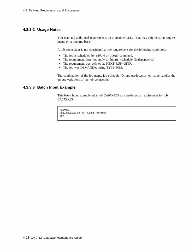
4.3 Defining Predecessors and Successors
4.3.3.2 Usage Notes
You may add additional requirements on a onetime basis. You may skip existing require-ments on a onetime basis.
A job connection is not considered a true requirement for the following conditions:
� The job is scheduled by a RUN or LOAD command.� The requirement does not apply to this run (schedule ID dependency).� The requirement was defined as NEXT-RUN=SKIP.� The job was DEMANDed using TYPE=RES.
The combination of the job name, job schedule ID, and predecessor job name handles theunique variations of the job connection.
4.3.3.3 Batch Input Example
This batch input example adds job CA07XX03 as a predecessor requirement for jobCA07XX05.
JOBCONN
UPD,JOB,CA�7XX�5,OPT=A,PRED=CA�7XX�3
DBM
4-18 CA-7 3.3 Database Maintenance Guide

4.3 Defining Predecessors and Successors
4.3.4 DB.3.4 - Input/Output Network Tasks Screen
Use this screen to define a CPU job's requirements (or connections) for workstation net-works. One network can be connected to multiple CPU jobs.
� �
--------------------- CA-7 INPUT/OUTPUT NETWORK TASKS ----------------------
FUNCTION: xxxxxxxx (FORMAT,LIST,UPD) PAGE nnnn
TASK FOR JOB: xxxxxxxx LIST-SCHID: nnn
OPT SCHID LEADTM NETWORK SUB-ID NWK-SCHID DESCRIPTION NEXT-RUN
x nnn nnnn xxxxxxxx xxxxxxxx nnn xxxxxxxx xxxx
x nnn nnnn xxxxxxxx xxxxxxxx nnn xxxxxxxx xxxx
x nnn nnnn xxxxxxxx xxxxxxxx nnn xxxxxxxx xxxx
x nnn nnnn xxxxxxxx xxxxxxxx nnn xxxxxxxx xxxx
x nnn nnnn xxxxxxxx xxxxxxxx nnn xxxxxxxx xxxx
x nnn nnnn xxxxxxxx xxxxxxxx nnn xxxxxxxx xxxx
x nnn nnnn xxxxxxxx xxxxxxxx nnn xxxxxxxx xxxx
x nnn nnnn xxxxxxxx xxxxxxxx nnn xxxxxxxx xxxx
x nnn nnnn xxxxxxxx xxxxxxxx nnn xxxxxxxx xxxx
x nnn nnnn xxxxxxxx xxxxxxxx nnn xxxxxxxx xxxx
x nnn nnnn xxxxxxxx xxxxxxxx nnn xxxxxxxx xxxx
x nnn nnnn xxxxxxxx xxxxxxxx nnn xxxxxxxx xxxx
x nnn nnnn xxxxxxxx xxxxxxxx nnn xxxxxxxx xxxx
x nnn nnnn xxxxxxxx xxxxxxxx nnn xxxxxxxx xxxx
x nnn nnnn xxxxxxxx xxxxxxxx nnn xxxxxxxx xxxx
OPTIONS: A=ADD,D=DELETE,U=UPDATE,C=PROCESSED,?=ERROR
PROGRAM: SM61 MSG-INDX: nn -- DB.3.4 -- yy.ddd / hh:mm:ss
MESSAGE:
( )
To display, enter:
� 4 as the FUNCTION on the DB.3 Menu screen.� 3.4 as the FUNCTION on the DB Menu screen.� DB.3.4 as the FUNCTION on any other menu or formatted input screen.� DB.3.4 or JOBCONN,NWK as a top line command.
To exit:
� Press the PF3 key to return to the DB.3 Menu screen except with the TSO-ISPFinterface when PF3 has been assigned to some other function.
� Move the cursor to the top line of the screen and enter the desired top line commandif yet another function is desired.
Chapter 4. Requirement Definitions 4-19
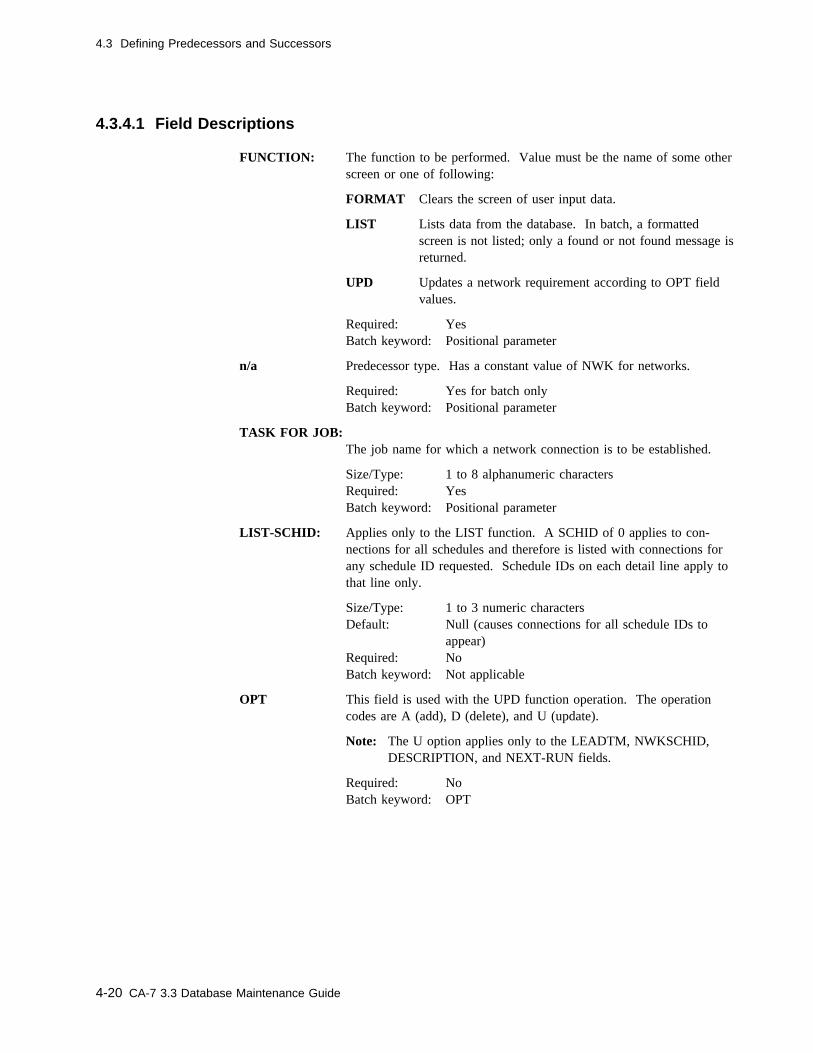
4.3 Defining Predecessors and Successors
4.3.4.1 Field Descriptions
FUNCTION: The function to be performed. Value must be the name of some otherscreen or one of following:
FORMAT Clears the screen of user input data.
LIST Lists data from the database. In batch, a formattedscreen is not listed; only a found or not found message isreturned.
UPD Updates a network requirement according to OPT fieldvalues.
Required: YesBatch keyword: Positional parameter
n/a Predecessor type. Has a constant value of NWK for networks.
Required: Yes for batch onlyBatch keyword: Positional parameter
TASK FOR JOB:The job name for which a network connection is to be established.
Size/Type: 1 to 8 alphanumeric charactersRequired: YesBatch keyword: Positional parameter
LIST-SCHID: Applies only to the LIST function. A SCHID of 0 applies to con-nections for all schedules and therefore is listed with connections forany schedule ID requested. Schedule IDs on each detail line apply tothat line only.
Size/Type: 1 to 3 numeric charactersDefault: Null (causes connections for all schedule IDs to
appear)Required: NoBatch keyword: Not applicable
OPT This field is used with the UPD function operation. The operationcodes are A (add), D (delete), and U (update).
Note: The U option applies only to the LEADTM, NWKSCHID,DESCRIPTION, and NEXT-RUN fields.
Required: NoBatch keyword: OPT
4-20 CA-7 3.3 Database Maintenance Guide

4.3 Defining Predecessors and Successors
SCHID Indicates the schedule ID (of this job) for which a network require-ment is applied. If omitted when the connection is made, the defaultis 0. A zero default cannot be specified for one connection and anonzero schedule ID for another connection to the same job with thesame network and sub-ID. An attempt to make such a connectionresults in an error message issued by CA-7.
Size/Type: 1 to 3 numeric characters from 0 through 255Default: 0 (indicates that the requirement holds for all
schedule IDs)Required: NoBatch keyword: SCHID
LEADTM For an input network, satisfaction lead time in hours. Values are:
0 The requirement is satisfied if the input network has beenprocessed since the last run of the job.
9999 The requirement is never considered initially satisfied whenthe job enters the request queue. The preprocess networkmust complete while this job is in the request queue.
nnnn The requirement is only considered satisfied if the networkhas been completed within the last nnnn hours (0 to 9998).
Default: 0Required: NoBatch keyword: LEADTM
For an output network, all postprocess network due-out times areadjusted (lead time is added) by this value.
Size/Type: 1 to 4 numeric characters specified as hhmm wherehours are 00 through 24 and minutes are 00 through59
Default: 0Required: NoBatch keyword: LEADTM
NETWORK The network name.
Size/Type: 1 to 8 alphanumeric charactersRequired: YesBatch keyword: NETWORK
Chapter 4. Requirement Definitions 4-21
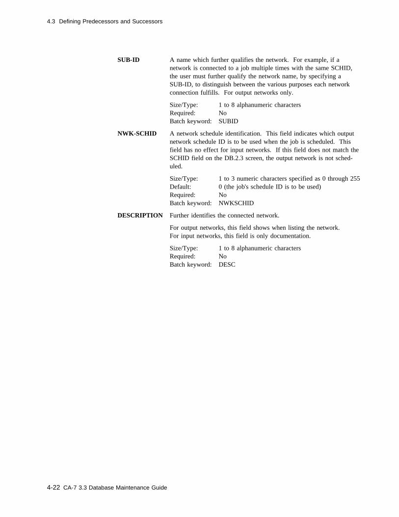
4.3 Defining Predecessors and Successors
SUB-ID A name which further qualifies the network. For example, if anetwork is connected to a job multiple times with the same SCHID,the user must further qualify the network name, by specifying aSUB-ID, to distinguish between the various purposes each networkconnection fulfills. For output networks only.
Size/Type: 1 to 8 alphanumeric charactersRequired: NoBatch keyword: SUBID
NWK-SCHID A network schedule identification. This field indicates which outputnetwork schedule ID is to be used when the job is scheduled. Thisfield has no effect for input networks. If this field does not match theSCHID field on the DB.2.3 screen, the output network is not sched-uled.
Size/Type: 1 to 3 numeric characters specified as 0 through 255Default: 0 (the job's schedule ID is to be used)Required: NoBatch keyword: NWKSCHID
DESCRIPTION Further identifies the connected network.
For output networks, this field shows when listing the network.For input networks, this field is only documentation.
Size/Type: 1 to 8 alphanumeric charactersRequired: NoBatch keyword: DESC
4-22 CA-7 3.3 Database Maintenance Guide
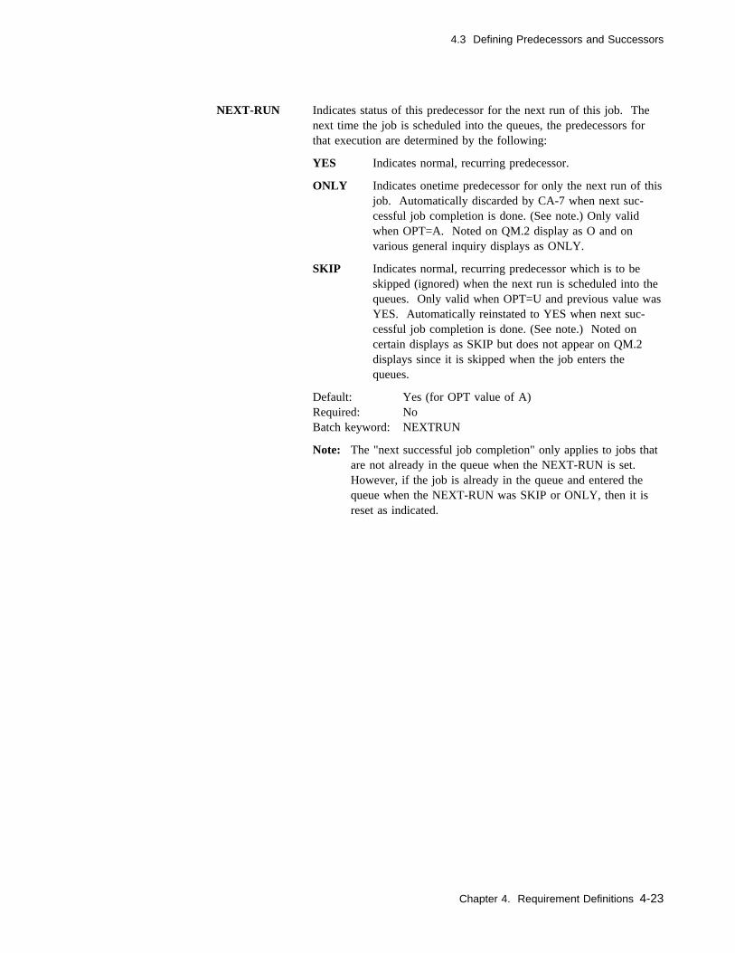
4.3 Defining Predecessors and Successors
NEXT-RUN Indicates status of this predecessor for the next run of this job. Thenext time the job is scheduled into the queues, the predecessors forthat execution are determined by the following:
YES Indicates normal, recurring predecessor.
ONLY Indicates onetime predecessor for only the next run of thisjob. Automatically discarded by CA-7 when next suc-cessful job completion is done. (See note.) Only validwhen OPT=A. Noted on QM.2 display as O and onvarious general inquiry displays as ONLY.
SKIP Indicates normal, recurring predecessor which is to beskipped (ignored) when the next run is scheduled into thequeues. Only valid when OPT=U and previous value wasYES. Automatically reinstated to YES when next suc-cessful job completion is done. (See note.) Noted oncertain displays as SKIP but does not appear on QM.2displays since it is skipped when the job enters thequeues.
Default: Yes (for OPT value of A)Required: NoBatch keyword: NEXTRUN
Note: The "next successful job completion" only applies to jobs thatare not already in the queue when the NEXT-RUN is set.However, if the job is already in the queue and entered thequeue when the NEXT-RUN was SKIP or ONLY, then it isreset as indicated.
Chapter 4. Requirement Definitions 4-23

4.3 Defining Predecessors and Successors
4.3.4.2 Usage Notes
You may add additional requirements on a onetime basis. You may skip existing require-ments on a onetime basis.
The combination of job name, job schedule ID, network name, and network sub-IDhandles any unique variations of a network connection.
A connected input network becomes a requirement for the job. An input network con-nection is not considered a true requirement for the following conditions:
� The job is scheduled by a RUN or LOAD command.� The requirement does not apply to this run (schedule ID dependency).� The requirement was defined as NEXT-RUN=SKIP.� The job was DEMANDed using TYPE=RES.
A connected output network is scheduled into the postprocess queue when the CPU jobenters the request queue. After the network is defined with the DB.5 screen, the networkis logically connected to one or more CPU jobs with the DB.3.5 screen. (Requiredscheduling parameters must also be entered with the DB.2.3 screen; the schedule,however, is not RESOLVed.)
4.3.4.3 Batch Input Example
This batch input example adds output network TESTOTNW as a successor to jobCA07XX01. Schedule ID 1 for TESTOTNW is used with station due-out times adjustedby 1 hour. A name of RPT1205 is used to further identify this network from any otherwhich may be associated with the job.
JOBCONN
UPD,NWK,CA�7XX�1,OPT=A,NETWORK=TESTOTNW,NWKSCHID=1,LEADTM=1��,SUBID=RPT12�5
DBM
4-24 CA-7 3.3 Database Maintenance Guide
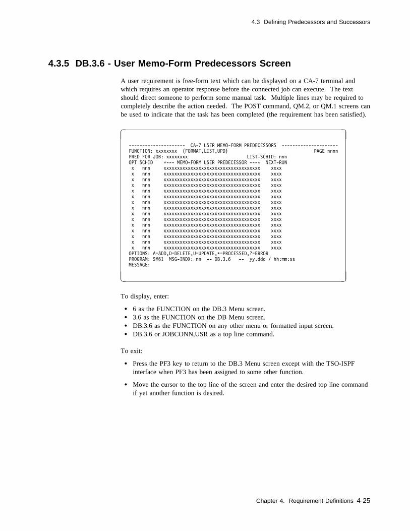
4.3 Defining Predecessors and Successors
4.3.5 DB.3.6 - User Memo-Form Predecessors Screen
A user requirement is free-form text which can be displayed on a CA-7 terminal andwhich requires an operator response before the connected job can execute. The textshould direct someone to perform some manual task. Multiple lines may be required tocompletely describe the action needed. The POST command, QM.2, or QM.1 screens canbe used to indicate that the task has been completed (the requirement has been satisfied).
� �
--------------------- CA-7 USER MEMO-FORM PREDECESSORS ---------------------
FUNCTION: xxxxxxxx (FORMAT,LIST,UPD) PAGE nnnn
PRED FOR JOB: xxxxxxxx LIST-SCHID: nnn
OPT SCHID C--- MEMO-FORM USER PREDECESSOR ---C NEXT-RUN
x nnn xxxxxxxxxxxxxxxxxxxxxxxxxxxxxxxxxxxx xxxx
x nnn xxxxxxxxxxxxxxxxxxxxxxxxxxxxxxxxxxxx xxxx
x nnn xxxxxxxxxxxxxxxxxxxxxxxxxxxxxxxxxxxx xxxx
x nnn xxxxxxxxxxxxxxxxxxxxxxxxxxxxxxxxxxxx xxxx
x nnn xxxxxxxxxxxxxxxxxxxxxxxxxxxxxxxxxxxx xxxx
x nnn xxxxxxxxxxxxxxxxxxxxxxxxxxxxxxxxxxxx xxxx
x nnn xxxxxxxxxxxxxxxxxxxxxxxxxxxxxxxxxxxx xxxx
x nnn xxxxxxxxxxxxxxxxxxxxxxxxxxxxxxxxxxxx xxxx
x nnn xxxxxxxxxxxxxxxxxxxxxxxxxxxxxxxxxxxx xxxx
x nnn xxxxxxxxxxxxxxxxxxxxxxxxxxxxxxxxxxxx xxxx
x nnn xxxxxxxxxxxxxxxxxxxxxxxxxxxxxxxxxxxx xxxx
x nnn xxxxxxxxxxxxxxxxxxxxxxxxxxxxxxxxxxxx xxxx
x nnn xxxxxxxxxxxxxxxxxxxxxxxxxxxxxxxxxxxx xxxx
x nnn xxxxxxxxxxxxxxxxxxxxxxxxxxxxxxxxxxxx xxxx
x nnn xxxxxxxxxxxxxxxxxxxxxxxxxxxxxxxxxxxx xxxx
OPTIONS: A=ADD,D=DELETE,U=UPDATE,C=PROCESSED,?=ERROR
PROGRAM: SM61 MSG-INDX: nn -- DB.3.6 -- yy.ddd / hh:mm:ss
MESSAGE:
( )
To display, enter:
� 6 as the FUNCTION on the DB.3 Menu screen.� 3.6 as the FUNCTION on the DB Menu screen.� DB.3.6 as the FUNCTION on any other menu or formatted input screen.� DB.3.6 or JOBCONN,USR as a top line command.
To exit:
� Press the PF3 key to return to the DB.3 Menu screen except with the TSO-ISPFinterface when PF3 has been assigned to some other function.
� Move the cursor to the top line of the screen and enter the desired top line commandif yet another function is desired.
Chapter 4. Requirement Definitions 4-25

4.3 Defining Predecessors and Successors
4.3.5.1 Field Descriptions
FUNCTION: The function to be performed. Value must be the name of some otherscreen or one of the following:
FORMAT Clears the screen of user input data.
LIST Lists data from the database. In batch, a formatted screenis not listed; only a found or not found message isreturned.
UPD Updates a user requirement according to OPT field values.
Required: YesBatch keyword: Positional parameter
n/a Predecessor type and has a constant value of USR for user text.
Required: Yes for batch onlyBatch keyword: Positional parameter
PRED FOR JOB:The job name for which user requirements are being defined.
Size/Type: 1 to 8 alphanumeric charactersRequired: YesBatch keyword: Positional parameter
LIST-SCHID: Applies only to the LIST function. A SCHID value of 0 applies toconnections for all schedules and therefore is listed with connectionsfor any schedule ID requested. Schedule IDs on each detail line applyto that line only.
Size/Type: 1 to 3 numeric charactersDefault: Null (causes connections for all schedule IDs to
appear)Required: NoBatch keyword: Not applicable
OPT This field is used with the UPD function to denote the type of con-nection operation. The operation codes are A (add), D (delete), and U(update).
Note: The U option applies only to the NEXT-RUN field. To changethe memo text, a delete (D) must be performed followed by anadd (A).
Required: NoBatch keyword: OPT
4-26 CA-7 3.3 Database Maintenance Guide
4.3 Defining Predecessors and Successors
SCHID Indicates the schedule ID (of this job) for which a user requirement isapplied. A zero default cannot be specified for one connection and anonzero schedule ID used for a subsequent connection to the same jobwith the same user requirement description. An attempt to make such aconnection results in an error message issued by CA-7.
Size/Type: 1 to 3 numeric characters from 0 through 255Default: 0 (indicates that the requirement holds for all
schedule IDs)Required: NoBatch keyword: SCHID
MEMO-FORM USER PREDECESSORThe free-form description of the user requirement. Not valid withOPT=U. Any text may be entered here that communicates the appro-priate requirement. Use this field to define requirements that cannot becontrolled automatically, for example ensuring that the transmission lineis up or calling the payroll department to verify that the edit is OK.You can express the requirements as a simple phrase, a sentence, or aparagraph. We recommend that you use as many words as you need toclarify exactly what has to be done. For example, "Make sure theonline system is down" is not as clear as "Make sure the online systemis down for the day" since online systems can come up and downduring the day. If the instructions do not fit in the 36 spaces on oneline, you can use as many lines as you need to explain them com-pletely. Each line then becomes a separate requirement which must besatisfied before the job can run.
We also recommend that this type of requirement be used only if nec-essary since manual intervention is required to satisfy it.
Note: If the text contains an apostrophe, parenthesis, or comma, therequirement cannot be added through BTI nor can it be postedthrough an external communicator.
Size/Type: 1 to 36 alphanumeric charactersRequired: YesBatch keyword: USR
NEXT-RUN Indicates status of this predecessor for the next run of this job. Thenext time the job is scheduled into the queues, the predecessors for thatexecution are determined by the following:
YES Indicates normal, recurring predecessor.
ONLY Indicates onetime predecessor for only the next run of thisjob. Automatically discarded by CA-7 when next suc-cessful job completion is done. (See note.) Only valid whenOPT=A. Noted on QM.2 display as O and on variousgeneral inquiry displays as ONLY.
Chapter 4. Requirement Definitions 4-27
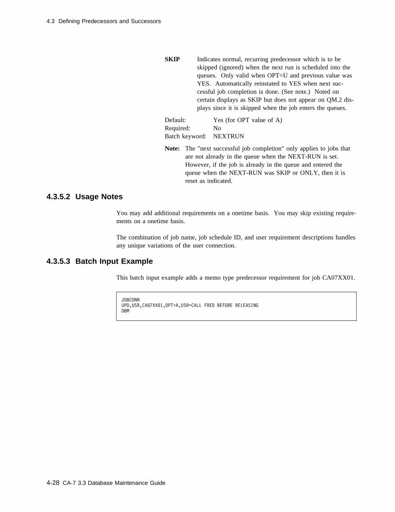
4.3 Defining Predecessors and Successors
SKIP Indicates normal, recurring predecessor which is to beskipped (ignored) when the next run is scheduled into thequeues. Only valid when OPT=U and previous value wasYES. Automatically reinstated to YES when next suc-cessful job completion is done. (See note.) Noted oncertain displays as SKIP but does not appear on QM.2 dis-plays since it is skipped when the job enters the queues.
Default: Yes (for OPT value of A)Required: NoBatch keyword: NEXTRUN
Note: The "next successful job completion" only applies to jobs thatare not already in the queue when the NEXT-RUN is set.However, if the job is already in the queue and entered thequeue when the NEXT-RUN was SKIP or ONLY, then it isreset as indicated.
4.3.5.2 Usage Notes
You may add additional requirements on a onetime basis. You may skip existing require-ments on a onetime basis.
The combination of job name, job schedule ID, and user requirement descriptions handlesany unique variations of the user connection.
4.3.5.3 Batch Input Example
This batch input example adds a memo type predecessor requirement for job CA07XX01.
JOBCONN
UPD,USR,CA�7XX�1,OPT=A,USR=CALL FRED BEFORE RELEASING
DBM
4-28 CA-7 3.3 Database Maintenance Guide

4.3 Defining Predecessors and Successors
4.3.6 DB.3.7 - Report IDs Created Screen
Use this screen to record information in the database regarding reports that are producedby CPU jobs. The information is optional and serves only as reference material foranyone wishing to review the information at a terminal. Other means of recording thisdata, including DB.4 functions, may be more desirable.
� �
------------------------- CA-7 REPORT IDS CREATED --------------------------
FUNCTION: xxxxxxxx (FORMAT,LIST,UPD) PAGE nnnn
IDS FROM JOB: xxxxxxxx LIST-SCHID: nnn
OPT SCHID REPORT ID STEPNAME DDNAME
x nnn xxxxxxxxxx xxxxxxxx xxxxxxxx
x nnn xxxxxxxxxx xxxxxxxx xxxxxxxx
x nnn xxxxxxxxxx xxxxxxxx xxxxxxxx
x nnn xxxxxxxxxx xxxxxxxx xxxxxxxx
x nnn xxxxxxxxxx xxxxxxxx xxxxxxxx
x nnn xxxxxxxxxx xxxxxxxx xxxxxxxx
x nnn xxxxxxxxxx xxxxxxxx xxxxxxxx
x nnn xxxxxxxxxx xxxxxxxx xxxxxxxx
x nnn xxxxxxxxxx xxxxxxxx xxxxxxxx
x nnn xxxxxxxxxx xxxxxxxx xxxxxxxx
x nnn xxxxxxxxxx xxxxxxxx xxxxxxxx
x nnn xxxxxxxxxx xxxxxxxx xxxxxxxx
x nnn xxxxxxxxxx xxxxxxxx xxxxxxxx
x nnn xxxxxxxxxx xxxxxxxx xxxxxxxx
x nnn xxxxxxxxxx xxxxxxxx xxxxxxxx
OPTIONS: A=ADD,D=DELETE,U=UPDATE,C=PROCESSED,?=ERROR
PROGRAM: SM61 MSG-INDX: nn -- DB.3.7 -- yy.ddd / hh:mm:ss
MESSAGE:
( )
To display, enter:
� 7 as the FUNCTION on the DB.3 Menu screen.� 3.7 as the FUNCTION on the DB Menu screen.� DB.3.7 as the FUNCTION value on any other menu or formatted input screen.� DB.3.7 or JOBCONN,RPT as a top line command.
To exit:
� Press the PF3 key to return to the DB.3 Menu screen except with the TSO-ISPFinterface when PF3 has been assigned to some other function.
� Move the cursor to the top line of the screen and enter the desired top line commandif yet another function is desired.
Chapter 4. Requirement Definitions 4-29

4.3 Defining Predecessors and Successors
4.3.6.1 Field Descriptions
FUNCTION: The function to be performed. Value must be the name of some otherscreen or one of the following:
FORMAT Clears the screen of input data.
LIST Lists data from the database. In batch, a formattedscreen is not listed; only a found or not found message isreturned.
UPD Updates report IDs according to OPT field values.
Required: YesBatch keyword: Positional parameter
n/a Predecessor type. Has a constant value of RPT for reports.
Required: Yes for batch onlyBatch keyword: Positional parameter
IDS FROM JOB:The job name for which report IDs are being defined.
Size/Type: 1 to 8 alphanumeric charactersRequired: YesBatch keyword: Positional parameter
LIST-SCHID: Applies only to the LIST function. A SCHID value of 0 applies toconnections for all schedules and therefore is listed with connectionsfor any schedule ID requested. Schedule IDs on each detail line applyto that line only.
Size/Type: 1 to 3 numeric charactersDefault: Null (causes connections for all schedule IDs to
appear)Required: NoBatch keyword: Not applicable
OPT This field is used with the UPD function to denote the type of con-nection operation. Operation code U (update) cannot be performed onthis field. If a change is needed, a delete (D) must be performed fol-lowed by an add (A).
Required: NoBatch keyword: OPT
4-30 CA-7 3.3 Database Maintenance Guide
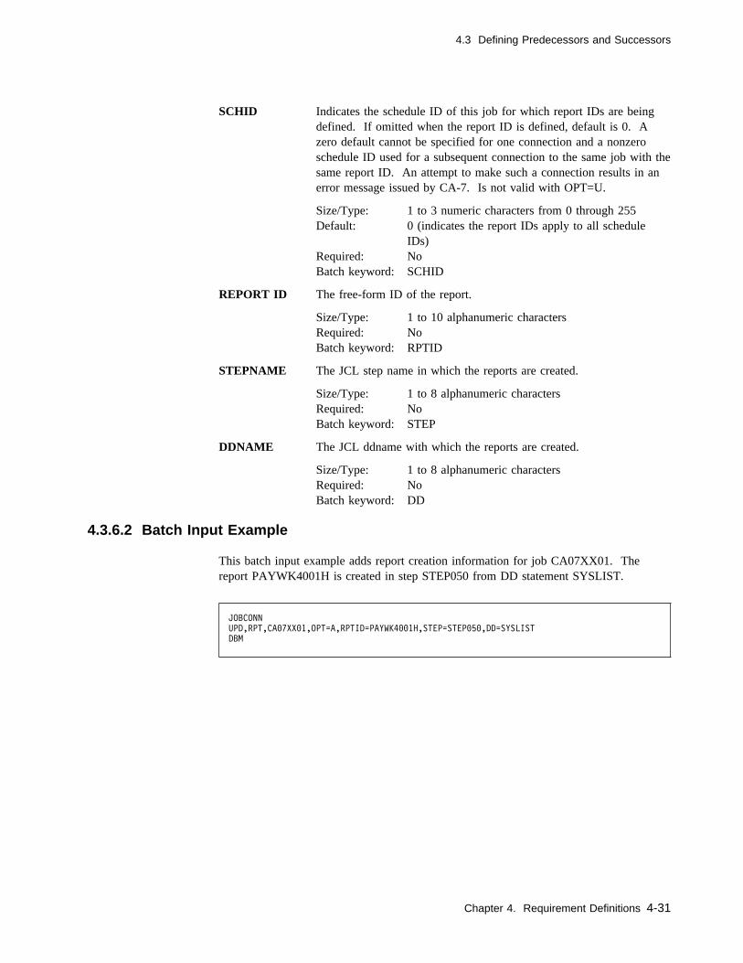
4.3 Defining Predecessors and Successors
SCHID Indicates the schedule ID of this job for which report IDs are beingdefined. If omitted when the report ID is defined, default is 0. Azero default cannot be specified for one connection and a nonzeroschedule ID used for a subsequent connection to the same job with thesame report ID. An attempt to make such a connection results in anerror message issued by CA-7. Is not valid with OPT=U.
Size/Type: 1 to 3 numeric characters from 0 through 255Default: 0 (indicates the report IDs apply to all schedule
IDs)Required: NoBatch keyword: SCHID
REPORT ID The free-form ID of the report.
Size/Type: 1 to 10 alphanumeric charactersRequired: NoBatch keyword: RPTID
STEPNAME The JCL step name in which the reports are created.
Size/Type: 1 to 8 alphanumeric charactersRequired: NoBatch keyword: STEP
DDNAME The JCL ddname with which the reports are created.
Size/Type: 1 to 8 alphanumeric charactersRequired: NoBatch keyword: DD
4.3.6.2 Batch Input Example
This batch input example adds report creation information for job CA07XX01. Thereport PAYWK4001H is created in step STEP050 from DD statement SYSLIST.
JOBCONN
UPD,RPT,CA�7XX�1,OPT=A,RPTID=PAYWK4��1H,STEP=STEP�5�,DD=SYSLIST
DBM
Chapter 4. Requirement Definitions 4-31

4-32 CA-7 3.3 Database Maintenance Guide

Chapter 5. Virtual Resource Management
Use the Virtual Resource Management (VRM) facility to define controls on job sub-mission based on resource availability. The resource connected to a job can represent areal resource such as a data set or a started task.
This facility provides the following features:
� Resource control at the job, system, or step level.
� Job submission control for jobs that use shared or exclusive resources.
� Job corequisite requirements.
Note: The Virtual Resource Management (VRM) facility manages resource utilizationthrough the use of tables internal to CA-7.
Resource dependencies are determined during the job submission process. Jobswaiting for resources will wait in the CA-7 ready queue with a status ofW-RSRC.
VRM resources are ignored for non-executable jobs.
Chapter 5. Virtual Resource Management 5-1
5.1 Resource Types
5.1 Resource Types
5.1.1 Shared Resources
There may be times when multiple jobs run using the same resource. You can define thisas a Shared resource requirement under the Virtual Resource Management facility. AShared resource connection indicates that multiple jobs can execute at the same timewhile using this resource.
5.1.2 Exclusive Resource
You can define the exclusive use of a resource under CA-7 VRM. This indicates that thejob requires exclusive use of the resource and that no other jobs connected to the resourcemay execute. If the 'resource' is unavailable exclusively at job submission time, the jobwaits in the CA-7 ready queue for the resource with a status of W-RSRC.
5.1.3 Corequisite Resources
A corequisite resource relationship indicates that a job executes based on the active orinactive status of the resource. If a job to resource connection is set up to require aspecific corequisite resource to be active prior to execution, CA-7 checks whether thecorequisite resource is active prior to submitting the job. The same is true for an inactivecorequisite resource. The indicated corequisite resource must be inactive before the job issubmitted for execution. To activate or deactivate a corequisite resource, issue thePRSQA and PRSQD commands respectively. You can do this in an online or batchenvironment.
Note: The following corequisite resource name prefixes are reserved:
FLOW@ CPM@
5.1.4 Address Space Resources
The CA-7 Virtual Resource Management facility provides the ability to control the exe-cution of a job based on the active or inactive status of an address space. For example,assume that JOBA requires that a CICS region be active for the job to be submitted.During the job submission cycle, CA-7 checks to see if the CICS region is active prior tosubmitting the job. If the region is not active, the job waits in the CA-7 ready queuewith a status of W-RSRC until the address space becomes active. This check occursduring every CA-7 submission cycle. The same process occurs for a job connected to anaddress space resource that requires that the address space be inactive. The address spaceresource requirement is only valid on the host CPU where CA-7 is executing.
5-2 CA-7 3.3 Database Maintenance Guide
5.1 Resource Types
5.1.5 Resource Count Resources
A resource count resource is a resource which is available for use based on a specificcount or number for this resource. The count value indicates the maximum occurrencesfor this resource count resource. When a job to resource connection is made to aresource count resource, a value is specified which identifies the total number of occur-rences for this resource that the job will use. When the job is submitted, this value issubtracted from the maximum amount available for the resource count resource.
For example, suppose that you have 20 tapes drives available at your site and you wish tomanage the usage of the tape drives by connecting jobs to a resource count resource. Theresource count resource can indirectly represent the tape drives by establishing amaximum total count available for the resource count resource and then connecting jobsto the resource and specifying the number of occurrences that each job will use.
Note: CA-7 reserves the following resource count resource name prefix:
VRMDD.
Chapter 5. Virtual Resource Management 5-3
5.2 Handling Resource Conflicts
5.2 Handling Resource Conflicts
VRM dynamically manages resource conflicts based on VRM database definitions andCA-7 job queue activity. This usually requires little or no manual intervention. CA-7detects when a job is no longer using a resource and frees it for use by other jobsaccording to the instructions in the jobs resource profile (the FREE value on the RM.1panel). However anomalies may occur if there are multiple instances of a job with thesame name.
For example, suppose JOBA is defined to use resource RSC1. Further assume that theRM.1 definition specifies TYPE=EXC and FREE=Y. If JOBA (say, job number 1)abends and is waiting in the Request Queue for restart, another instance of JOBA (jobnumber 2) may move to the ready queue for submission. However, JOBA (1) still hasexclusive control of the RSC1 resource that was acquired when it was initially submitted.Hence, JOBA (2) will not submit. Instead it will wait in the ready queue for the RSC1resource to become available. An LQ display will show that the status of JOBA (2) isW-RSRC.
In order to allow JOBA (2) to run, one must take manual corrective action such ascanceling or forcing completion of JOBA (1). JOBA (1) cannot be submitted whileJOBA (2) is in the ready queue.
An initialization file option is provided to streamline the handling of such conflicts.
See the discussion of the OPTIONS statement keyword JSOP in the CA-7 Systems Pro-grammer Guide for information on handling these anomalies.
5-4 CA-7 3.3 Database Maintenance Guide

5.3 VRM Menu Screen
5.3 VRM Menu Screen
Use the RM (Resource Management) Menu screen to select the Virtual Resource Man-agement functions.
� � -------------------- CA-7 VIRTUAL RESOURCE MANAGEMENT MENU -------------------
FUNCTION ==>
RESOURCE MANAGEMENT OPTIONS:
1 - JOB RESOURCE MANAGEMENT
2 - JOB RESOURCE CROSS REFERENCE LIST
3 - ACTIVE JOB RESOURCES DISPLAY
4 - PENDING RESOURCES JOB DISPLAY
5 - JOBS WAITING ON RESOURCES DISPLAY
6 - COREQUISITE RESOURCES LIST
7 - RESOURCE COUNT RESOURCE MANAGEMENT
PROGRAM: RSC� MSG-INDX: �� -- RM -- yy.266 / 13:21:42
MESSAGE: SPECIFY DESIRED OPTION OR ENTER A COMMAND ON THE TOP LINE
( )
To display, enter:
� RM as a top line command.� RM as the FUNCTION value on any other menu or formatted input screen.
To exit, enter:
� The name of an online screen as the FUNCTION value or move the cursor to the topline and enter a top line command if some other function is desired.
5.3.1 Usage Notes
Select the desired function by entering its value as the FUNCTION and pressing theEnter key.
Chapter 5. Virtual Resource Management 5-5

5.4 RM.1 Job Resource Management Screen
5.4 RM.1 Job Resource Management Screen
Use this screen to list, add, update, or delete resource connections by job. It generatesthe VRM static type J and R records maintained on the VRM database component.
� � -------------------------- CA-7 JOB RESOURCE MANAGEMENT -----------------------
FUNCTION ====> (FORMAT,LIST,UPD)
JOB: LIST-SCHID: PAGE ���1
OPT SCHID RESOURCE NAME STEPNAME TYPE FREE
OPTIONS: A=ADD D=DELETE U=UPDATE C=PROCESSED ?=ERROR
PROGRAM: RSC1 MSG-INDX: �� -- RM.1 -- yy.ddd / hh:mm:ss
MESSAGE: ENTER FUNCTION, TRANSFER OR ENTER A COMMAND ON THE TOP LINE
( )
To display, enter:
� 1 as the FUNCTION on the RM Menu screen.� RM.1 as the FUNCTION value on any other menu or formatted input screen.� RM.1 as a top line command.
To exit:
� Press the PF3 key to return to the RM Menu screen except with the TSO/ISPF inter-face when PF3 has been assigned to some other function.
� Move the cursor to the top line of the screen and enter the desired top line commandif yet another function is desired.
5-6 CA-7 3.3 Database Maintenance Guide
5.4 RM.1 Job Resource Management Screen
5.4.1 Field Descriptions
FUNCTION The function to be performed. Value must be the name of some otherscreen or one of the following:
FORMAT Clears the screen of user input data.
LIST Lists the resources connected to the specified job and scheduleID.
UPD Performs updating option indicated by the OPT parameterbelow.
Required: YesBatch keyword: Positional parameter
JOB: The job name on which the indicated function is to be performed.
Size/Type: 1 to 8 alphanumeric charactersRequired: YesBatch keyword: JOB
LIST-SCHID:Applies only to the LIST function. A SCHID value of 0 applies to con-nections for all schedules and therefore is listed with connections for anyschedule ID requested. Schedule IDs on each detail line apply to that lineonly.
Size/Type: 1 to 3 numeric characters from 0 to 255Default: Null (causes connections for all schedule IDs to appear)Required: NoBatch keyword: Not applicable
OPT This field is used with the UPD function to denote the type of connectionoperation. The operation codes are A (add), U (update), and D (delete).
Required: YesBatch keyword: OPT
SCHID Indicates the schedule ID (of this job) for which a user requirement isapplied. A zero default cannot be specified for one connection and anonzero schedule ID used for a subsequent connection to the same job withthe same user requirement description. An attempt to make such a con-nection results in an error message issued by CA-7.
Size/Type: 1 to 3 numeric characters from 0 through 255Default: 0 (indicates that the requirement holds for all schedule
IDs)Required: NoBatch keyword: SCHID
Chapter 5. Virtual Resource Management 5-7

5.4 RM.1 Job Resource Management Screen
RESOURCE NAMEThe resource name being connected to the job.
Size/Type: 1 to 44 characters - the first character must be nonblankand no embedded blanks
Required: YesException: If the resource connection is made to a resource count
resource, then the resource name can be from 1 to 39characters followed by a / (slash) and a 1 to 4 numericvalue indicating the number of occurrences for theresource that the job will use.
Batch keyword: RSRC
STEPNAMEThe resource will be freed at the conclusion of the named job step. Notvalid for types ASX and CRQ.
Size/Type: 1 to 8 alphanumeric charactersRequired: NoBatch keyword: STEP
Note: The stepname field applies to the first occurrence of the stepnameencountered in the job stream. This includes any reference to thestepname embedded in a PROC.
TYPE This field determines the usage of the resource by the job. The validresource usage types are:
ASX An address space resource. This controls the submission of thejob based on the status of an address space.
Note: The address space resource requirement is only validon the host CPU where CA-7 is executing.
CRQ A corequisite resource. The job cannot be submitted if theresource is active or inactive (see the FREE option). Thecorequisite resource must be activated or deactivated using thePRSQA or PRSQD command. This can be performed in anonline or batch environment.
EXC An exclusive resource. Only one job can be active with thisresource.
RCT A resource count resource. This controls the submission of thejob based on the number of available occurrences within aresource count type resource when adding a resource countresource connection. The resource name can be from 1 to 39characters followed by a / (slash) and a 4-character numericvalue indicating the number of resource occurrences this jobwill use.
SHR A shared resource. Multiple jobs can be active with the sameresource.
Required: Yes
5-8 CA-7 3.3 Database Maintenance Guide
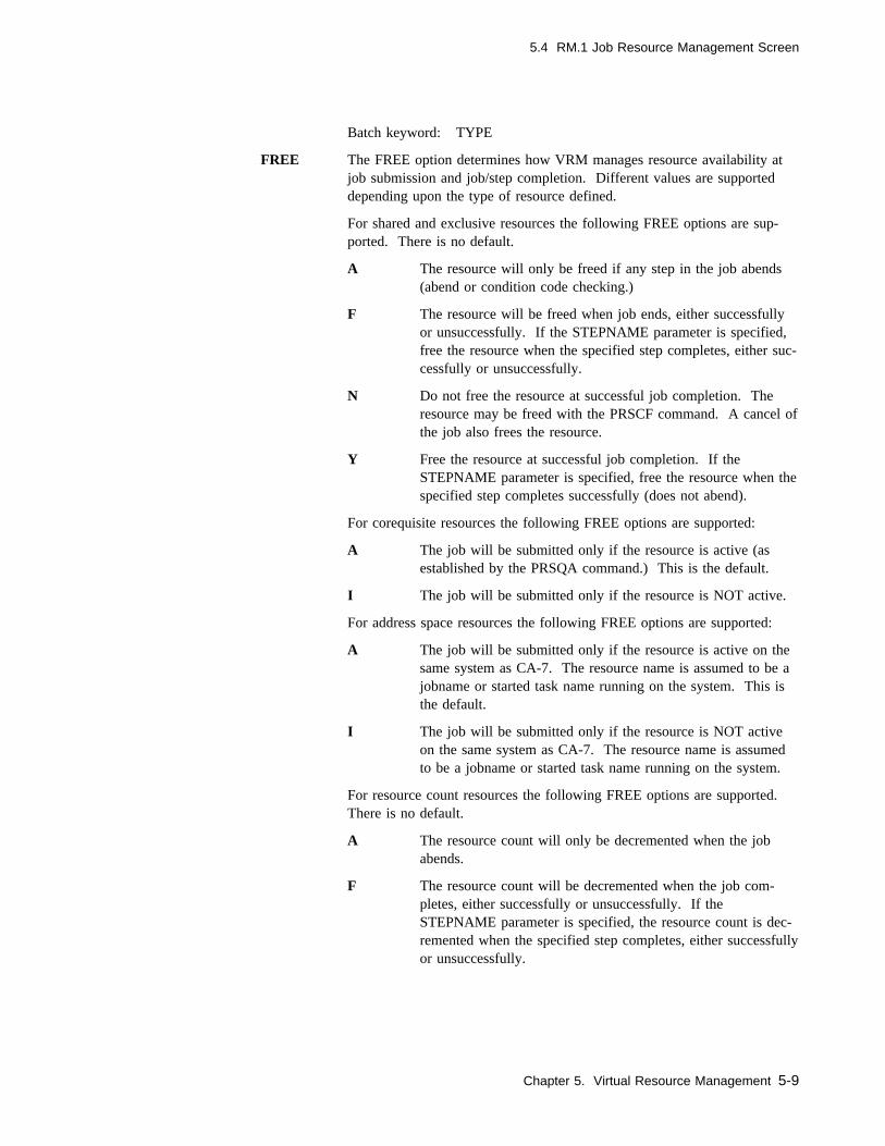
5.4 RM.1 Job Resource Management Screen
Batch keyword: TYPE
FREE The FREE option determines how VRM manages resource availability atjob submission and job/step completion. Different values are supporteddepending upon the type of resource defined.
For shared and exclusive resources the following FREE options are sup-ported. There is no default.
A The resource will only be freed if any step in the job abends(abend or condition code checking.)
F The resource will be freed when job ends, either successfullyor unsuccessfully. If the STEPNAME parameter is specified,free the resource when the specified step completes, either suc-cessfully or unsuccessfully.
N Do not free the resource at successful job completion. Theresource may be freed with the PRSCF command. A cancel ofthe job also frees the resource.
Y Free the resource at successful job completion. If theSTEPNAME parameter is specified, free the resource when thespecified step completes successfully (does not abend).
For corequisite resources the following FREE options are supported:
A The job will be submitted only if the resource is active (asestablished by the PRSQA command.) This is the default.
I The job will be submitted only if the resource is NOT active.
For address space resources the following FREE options are supported:
A The job will be submitted only if the resource is active on thesame system as CA-7. The resource name is assumed to be ajobname or started task name running on the system. This isthe default.
I The job will be submitted only if the resource is NOT activeon the same system as CA-7. The resource name is assumedto be a jobname or started task name running on the system.
For resource count resources the following FREE options are supported.There is no default.
A The resource count will only be decremented when the jobabends.
F The resource count will be decremented when the job com-pletes, either successfully or unsuccessfully. If theSTEPNAME parameter is specified, the resource count is dec-remented when the specified step completes, either successfullyor unsuccessfully.
Chapter 5. Virtual Resource Management 5-9
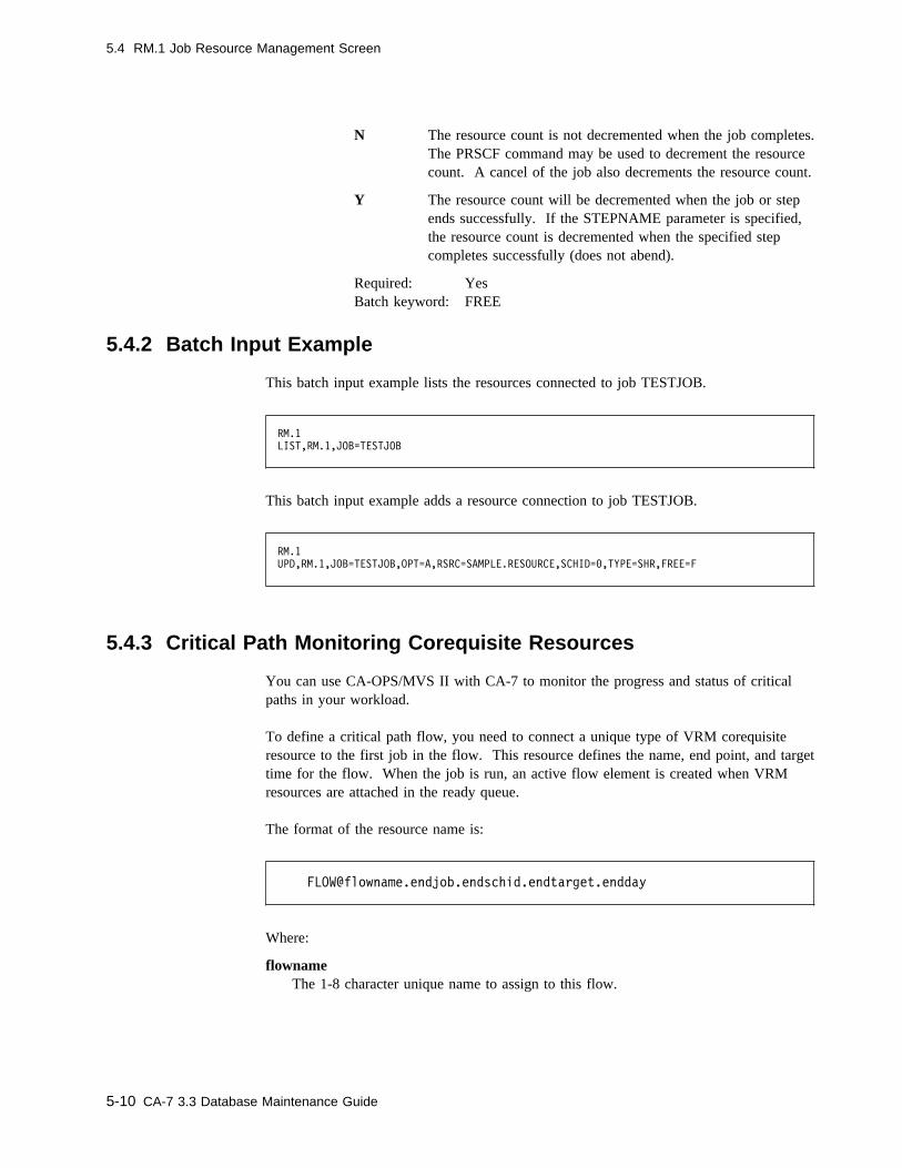
5.4 RM.1 Job Resource Management Screen
N The resource count is not decremented when the job completes.The PRSCF command may be used to decrement the resourcecount. A cancel of the job also decrements the resource count.
Y The resource count will be decremented when the job or stepends successfully. If the STEPNAME parameter is specified,the resource count is decremented when the specified stepcompletes successfully (does not abend).
Required: YesBatch keyword: FREE
5.4.2 Batch Input Example
This batch input example lists the resources connected to job TESTJOB.
RM.1
LIST,RM.1,JOB=TESTJOB
This batch input example adds a resource connection to job TESTJOB.
RM.1
UPD,RM.1,JOB=TESTJOB,OPT=A,RSRC=SAMPLE.RESOURCE,SCHID=�,TYPE=SHR,FREE=F
5.4.3 Critical Path Monitoring Corequisite Resources
You can use CA-OPS/MVS II with CA-7 to monitor the progress and status of criticalpaths in your workload.
To define a critical path flow, you need to connect a unique type of VRM corequisiteresource to the first job in the flow. This resource defines the name, end point, and targettime for the flow. When the job is run, an active flow element is created when VRMresources are attached in the ready queue.
The format of the resource name is:
Where:
flownameThe 1-8 character unique name to assign to this flow.
5-10 CA-7 3.3 Database Maintenance Guide

5.4 RM.1 Job Resource Management Screen
endjobThe job name of the last job in this flow.
endschidThe schedule ID of the last job in this flow.
endtargetThe target time that the ending job should complete by (hhmm).
enddayAn optional parameter to add day(s) to the target time (.n).
5.4.3.1 Example
5.4.3.2 Notes
1. The resource type must be corequisite (CRQ).
2. The resource name must begin with FLOW@.
3. The flowname, end job name, end schedule ID, and end target are required parame-ters and must be separated by periods.
4. The end day parameter is optional. If specified it must be 1 digit (0-9) separatedfrom the end target by a period. A value of 1 will cause 24 hours to be added to thetarget time. A value of 2 will cause 48 hours to be added, and so forth.
5. The 'FREE' type must be specified on the definition (A or I), however, it is ignoredif the CPM facility is active. Since these resources are treated as normal corequisitesif the CPM facility is not active, you may wish to specify I (inactive) for the FREEtype.
6. VRM RESOURCES ARE NEVER ATTACHED TO NON-EXECUTABLE JOBS.Thus, the starting job of any flow must be executable.
See the CA-7 Interfaces Guide and the CA-OPS/MVS II documentation for more informa-tion on the Critical Path Monitoring facility.
Chapter 5. Virtual Resource Management 5-11
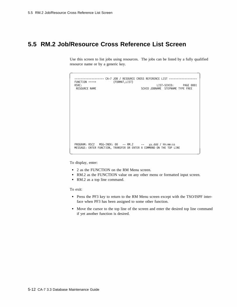
5.5 RM.2 Job/Resource Cross Reference List Screen
5.5 RM.2 Job/Resource Cross Reference List Screen
Use this screen to list jobs using resources. The jobs can be listed by a fully qualifiedresource name or by a generic key.
� � ------------------- CA-7 JOB / RESOURCE CROSS REFERENCE LIST ------------------
FUNCTION ====> (FORMAT,LIST)
RSRC: LIST-SCHID: PAGE ���1
RESOURCE NAME SCHID JOBNAME STEPNAME TYPE FREE
PROGRAM: RSC2 MSG-INDX: �� -- RM.2 -- yy.ddd / hh:mm:ss
MESSAGE: ENTER FUNCTION, TRANSFER OR ENTER A COMMAND ON THE TOP LINE
( )
To display, enter:
� 2 as the FUNCTION on the RM Menu screen.� RM.2 as the FUNCTION value on any other menu or formatted input screen.� RM.2 as a top line command.
To exit:
� Press the PF3 key to return to the RM Menu screen except with the TSO/ISPF inter-face when PF3 has been assigned to some other function.
� Move the cursor to the top line of the screen and enter the desired top line commandif yet another function is desired.
5-12 CA-7 3.3 Database Maintenance Guide
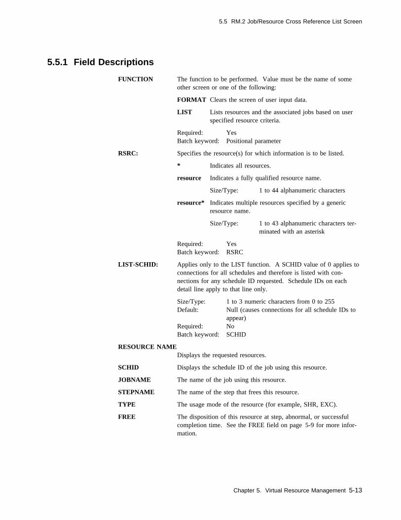
5.5 RM.2 Job/Resource Cross Reference List Screen
5.5.1 Field Descriptions
FUNCTION The function to be performed. Value must be the name of someother screen or one of the following:
FORMAT Clears the screen of user input data.
LIST Lists resources and the associated jobs based on userspecified resource criteria.
Required: YesBatch keyword: Positional parameter
RSRC: Specifies the resource(s) for which information is to be listed.
* Indicates all resources.
resource Indicates a fully qualified resource name.
Size/Type: 1 to 44 alphanumeric characters
resource* Indicates multiple resources specified by a genericresource name.
Size/Type: 1 to 43 alphanumeric characters ter-minated with an asterisk
Required: YesBatch keyword: RSRC
LIST-SCHID: Applies only to the LIST function. A SCHID value of 0 applies toconnections for all schedules and therefore is listed with con-nections for any schedule ID requested. Schedule IDs on eachdetail line apply to that line only.
Size/Type: 1 to 3 numeric characters from 0 to 255Default: Null (causes connections for all schedule IDs to
appear)Required: NoBatch keyword: SCHID
RESOURCE NAMEDisplays the requested resources.
SCHID Displays the schedule ID of the job using this resource.
JOBNAME The name of the job using this resource.
STEPNAME The name of the step that frees this resource.
TYPE The usage mode of the resource (for example, SHR, EXC).
FREE The disposition of this resource at step, abnormal, or successfulcompletion time. See the FREE field on page 5-9 for more infor-mation.
Chapter 5. Virtual Resource Management 5-13

5.5 RM.2 Job/Resource Cross Reference List Screen
5.5.2 Batch Input Example
This batch input example lists all the cross-reference entries for resources that begin withPROD.
RM.2
LIST,RM.2,RSRC=PRODC
5-14 CA-7 3.3 Database Maintenance Guide
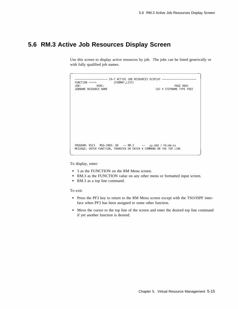
5.6 RM.3 Active Job Resources Display Screen
5.6 RM.3 Active Job Resources Display Screen
Use this screen to display active resources by job. The jobs can be listed generically orwith fully qualified job names.
� � --------------------- CA-7 ACTIVE JOB RESOURCES DISPLAY ----------------------
FUNCTION ====> (FORMAT,LIST)
JOB: RSRC: PAGE ���1
JOBNAME RESOURCE NAME CA7 # STEPNAME TYPE FREE
PROGRAM: RSC3 MSG-INDX: �� -- RM.3 -- yy.ddd / hh:mm:ss
MESSAGE: ENTER FUNCTION, TRANSFER OR ENTER A COMMAND ON THE TOP LINE
( )
To display, enter:
� 3 as the FUNCTION on the RM Menu screen.� RM.3 as the FUNCTION value on any other menu or formatted input screen.� RM.3 as a top line command.
To exit:
� Press the PF3 key to return to the RM Menu screen except with the TSO/ISPF inter-face when PF3 has been assigned to some other function.
� Move the cursor to the top line of the screen and enter the desired top line commandif yet another function is desired.
Chapter 5. Virtual Resource Management 5-15
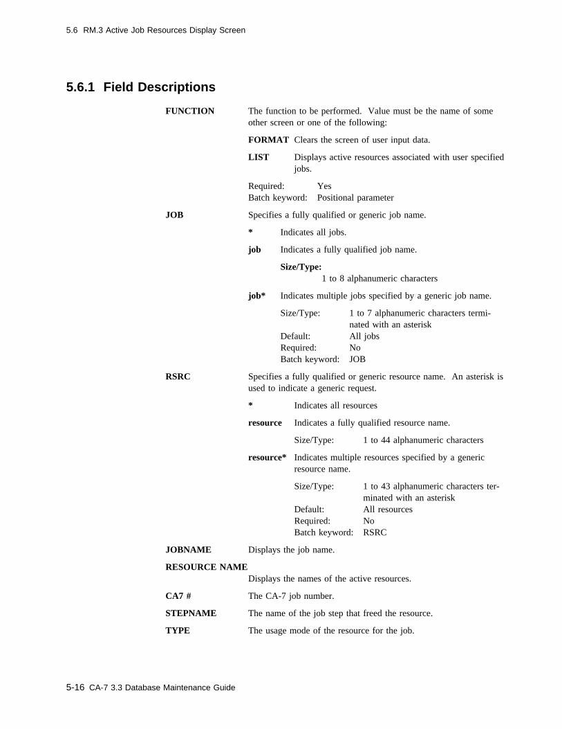
5.6 RM.3 Active Job Resources Display Screen
5.6.1 Field Descriptions
FUNCTION The function to be performed. Value must be the name of someother screen or one of the following:
FORMAT Clears the screen of user input data.
LIST Displays active resources associated with user specifiedjobs.
Required: YesBatch keyword: Positional parameter
JOB Specifies a fully qualified or generic job name.
* Indicates all jobs.
job Indicates a fully qualified job name.
Size/Type:1 to 8 alphanumeric characters
job* Indicates multiple jobs specified by a generic job name.
Size/Type: 1 to 7 alphanumeric characters termi-nated with an asterisk
Default: All jobsRequired: NoBatch keyword: JOB
RSRC Specifies a fully qualified or generic resource name. An asterisk isused to indicate a generic request.
* Indicates all resources
resource Indicates a fully qualified resource name.
Size/Type: 1 to 44 alphanumeric characters
resource* Indicates multiple resources specified by a genericresource name.
Size/Type: 1 to 43 alphanumeric characters ter-minated with an asterisk
Default: All resourcesRequired: NoBatch keyword: RSRC
JOBNAME Displays the job name.
RESOURCE NAMEDisplays the names of the active resources.
CA7 # The CA-7 job number.
STEPNAME The name of the job step that freed the resource.
TYPE The usage mode of the resource for the job.
5-16 CA-7 3.3 Database Maintenance Guide

5.6 RM.3 Active Job Resources Display Screen
FREE The disposition of the resource at job completion time or the statusof a corequisite resource type.
5.6.2 Batch Input Example
This batch input example lists all active resources for jobs that begin with PAY.
RM.3
LIST,RM.3,JOB=PAYC,RSRC=C
Chapter 5. Virtual Resource Management 5-17

5.7 RM.4 Pending Resources Job Display Screen
5.7 RM.4 Pending Resources Job Display Screen
Use this screen to display all pending resources with an associated job name. A pendingresource is a nonfreed resource connected to a job which has already executed and hasbeen purged from the request queue. This resource can only be freed by using thePRSCF command. The pending resources can be listed using a generic or fully qualifiedresource name.
� � --------------------- CA-7 PENDING RESOURCES JOB DISPLAY --------------------
FUNCTION ====> (FORMAT,LIST)
RSRC: PAGE ���1
RESOURCE NAME JOBNAME CA7 JOB# TYPE
PROGRAM: RSC4 MSG-INDX: �� -- RM.4 -- yy.ddd / hh:mm:ss
MESSAGE: ENTER FUNCTION, TRANSFER OR ENTER A COMMAND ON THE TOP LINE
( )
To display, enter:
� 4 as the FUNCTION on the RM Menu screen.� RM.4 as the FUNCTION value on any other menu or formatted input screen.� RM.4 as a top line command.
To exit:
� Press the PF3 key to return to the RM Menu screen except with the TSO/ISPF inter-face when PF3 has been assigned to some other function.
� Move the cursor to the top line of the screen and enter the desired top line commandif yet another function is desired.
5-18 CA-7 3.3 Database Maintenance Guide
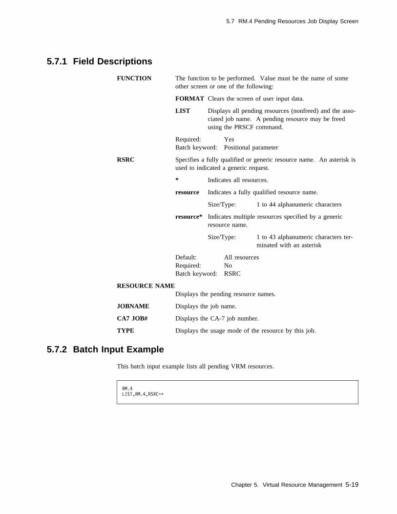
5.7 RM.4 Pending Resources Job Display Screen
5.7.1 Field Descriptions
FUNCTION The function to be performed. Value must be the name of someother screen or one of the following:
FORMAT Clears the screen of user input data.
LIST Displays all pending resources (nonfreed) and the asso-ciated job name. A pending resource may be freedusing the PRSCF command.
Required: YesBatch keyword: Positional parameter
RSRC Specifies a fully qualified or generic resource name. An asterisk isused to indicated a generic request.
* Indicates all resources.
resource Indicates a fully qualified resource name.
Size/Type: 1 to 44 alphanumeric characters
resource* Indicates multiple resources specified by a genericresource name.
Size/Type: 1 to 43 alphanumeric characters ter-minated with an asterisk
Default: All resourcesRequired: NoBatch keyword: RSRC
RESOURCE NAMEDisplays the pending resource names.
JOBNAME Displays the job name.
CA7 JOB# Displays the CA-7 job number.
TYPE Displays the usage mode of the resource by this job.
5.7.2 Batch Input Example
This batch input example lists all pending VRM resources.
RM.4
LIST,RM.4,RSRC=C
Chapter 5. Virtual Resource Management 5-19

5.8 RM.5 Jobs Waiting on Resources Screen
5.8 RM.5 Jobs Waiting on Resources Screen
Use this screen to display jobs waiting for resources. It can be used to show theresources that a job is waiting for when the job shows a status of W-RSRC on the ListQueue (LQ) display. However, ASX resources may not always show on the RM.5screen. This can occur because ASX resources are only checked periodically (approxi-mately two minute intervals) after the initial test for a job.
� � ------------------------ CA-7 JOBS WAITING ON RESOURCES ----------------------
FUNCTION ====> (FORMAT,LIST)
JOB: LIST-SCHID: PAGE ���1
JOB NAME RESOURCE NAME SCHID STEPNAME TYPE FREE
PROGRAM: RSC5 MSG-INDX: �� -- RM.5 -- yy.ddd / hh:mm:ss
MESSAGE: ENTER FUNCTION, TRANSFER OR ENTER A COMMAND ON THE TOP LINE
( )
To display, enter:
� 5 as the FUNCTION on the RM Menu screen.� RM.5 as the FUNCTION value on any other menu or formatted input screen.� RM.5 as a top line command.
To exit:
� Press the PF3 key to return to the RM Menu screen except with the TSO/ISPF inter-face when PF3 has been assigned to some other function.
� Move the cursor to the top line of the screen and enter the desired top line commandif yet another function is desired.
5-20 CA-7 3.3 Database Maintenance Guide

5.8 RM.5 Jobs Waiting on Resources Screen
5.8.1 Field Descriptions
FUNCTION The function to be performed. Value must be the name of some otherscreen or one of the following:
FORMAT Clears the screen of user input data.
LIST Displays jobs waiting for resources based on user specifiedjob name and schedule ID criteria.
Required: YesBatch keyword: Positional parameter
JOB Specifies a fully qualified or generic job name.
* Indicates all jobs.
job Indicates a fully qualified job name.
Size/Type: 1 to 8 alphanumeric characters
job* Indicates multiple jobs specified by a generic job name.
Size/Type: 1 to 7 alphanumeric characters termi-nated with an asterisk
Default: All jobsRequired: NoBatch keyword: JOB
LIST-SCHID Applies only to the LIST function. A SCHID value of 0 applies toconnections for all schedules and therefore is listed with connectionsfor any schedule ID requested. Schedule IDs on each detail line applyto that line only.
Size/Type: 1 to 3 numeric characters from 0 to 255Default: Null (causes connections for all schedule IDs to
appear)Required: NoBatch keyword: SCHID
JOB NAME Displays the job name of the job awaiting the resource.
RESOURCE NAMEDisplays the name of the nonavailable resource.
Chapter 5. Virtual Resource Management 5-21
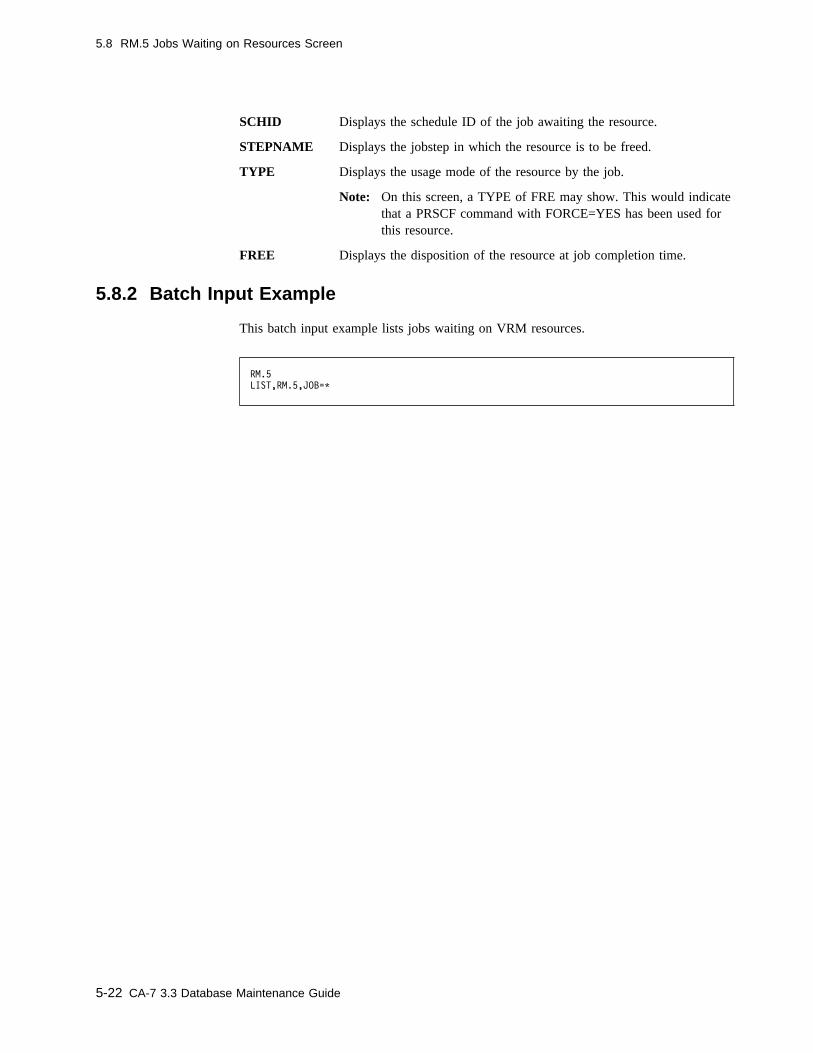
5.8 RM.5 Jobs Waiting on Resources Screen
SCHID Displays the schedule ID of the job awaiting the resource.
STEPNAME Displays the jobstep in which the resource is to be freed.
TYPE Displays the usage mode of the resource by the job.
Note: On this screen, a TYPE of FRE may show. This would indicatethat a PRSCF command with FORCE=YES has been used forthis resource.
FREE Displays the disposition of the resource at job completion time.
5.8.2 Batch Input Example
This batch input example lists jobs waiting on VRM resources.
RM.5
LIST,RM.5,JOB=C
5-22 CA-7 3.3 Database Maintenance Guide

5.9 RM.6 Corequisite Resources List Screen
5.9 RM.6 Corequisite Resources List Screen
Use this screen to list active corequisite resources.
� � ------------------------ CA-7 COREQUISITE RESOURCES LIST ----------------------
FUNCTION ====> (FORMAT,LIST)
RSRC: PAGE ���1
CO-REQ RESOURCE NAME
PROGRAM: RSC6 MSG-INDX: �� -- RM.6 -- yy.ddd / hh:mm:ss
MESSAGE: ENTER FUNCTION, TRANSFER OR ENTER A COMMAND ON THE TOP LINE
( )
To display, enter:
� 6 as the FUNCTION on the RM Menu screen.� RM.6 as the FUNCTION value on any other menu or formatted input screen.� RM.6 as a top line command.
To exit:
� Press the PF3 key to return to the RM Menu screen except with the TSO/ISPF inter-face when PF3 has been assigned to some other function.
� Move the cursor to the top line of the screen and enter the desired top line commandif yet another function is desired.
Chapter 5. Virtual Resource Management 5-23
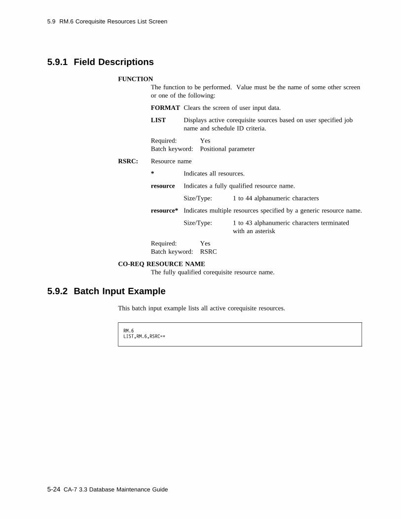
5.9 RM.6 Corequisite Resources List Screen
5.9.1 Field Descriptions
FUNCTIONThe function to be performed. Value must be the name of some other screenor one of the following:
FORMAT Clears the screen of user input data.
LIST Displays active corequisite sources based on user specified jobname and schedule ID criteria.
Required: YesBatch keyword: Positional parameter
RSRC: Resource name
* Indicates all resources.
resource Indicates a fully qualified resource name.
Size/Type: 1 to 44 alphanumeric characters
resource* Indicates multiple resources specified by a generic resource name.
Size/Type: 1 to 43 alphanumeric characters terminatedwith an asterisk
Required: YesBatch keyword: RSRC
CO-REQ RESOURCE NAMEThe fully qualified corequisite resource name.
5.9.2 Batch Input Example
This batch input example lists all active corequisite resources.
RM.6
LIST,RM.6,RSRC=C
5-24 CA-7 3.3 Database Maintenance Guide
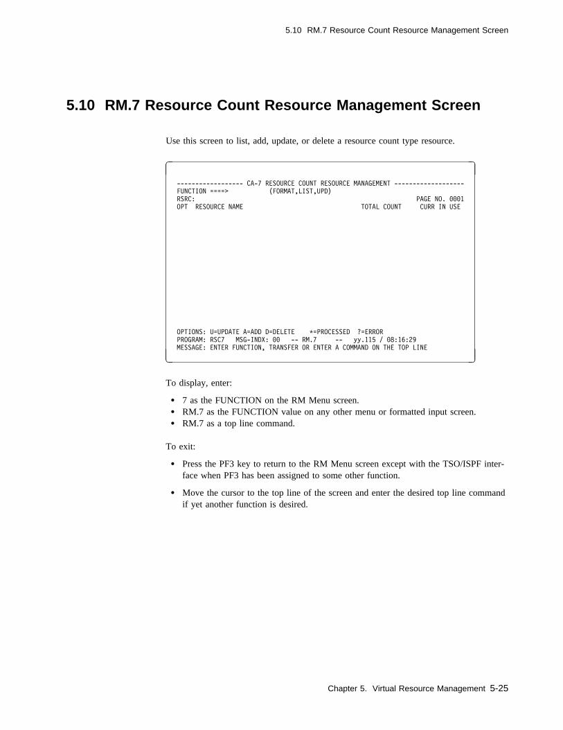
5.10 RM.7 Resource Count Resource Management Screen
5.10 RM.7 Resource Count Resource Management Screen
Use this screen to list, add, update, or delete a resource count type resource.
� �
------------------ CA-7 RESOURCE COUNT RESOURCE MANAGEMENT -------------------
FUNCTION ====> (FORMAT,LIST,UPD)
RSRC: PAGE NO. ���1
OPT RESOURCE NAME TOTAL COUNT CURR IN USE
OPTIONS: U=UPDATE A=ADD D=DELETE C=PROCESSED ?=ERROR
PROGRAM: RSC7 MSG-INDX: �� -- RM.7 -- yy.115 / �8:16:29
MESSAGE: ENTER FUNCTION, TRANSFER OR ENTER A COMMAND ON THE TOP LINE
( )
To display, enter:
� 7 as the FUNCTION on the RM Menu screen.� RM.7 as the FUNCTION value on any other menu or formatted input screen.� RM.7 as a top line command.
To exit:
� Press the PF3 key to return to the RM Menu screen except with the TSO/ISPF inter-face when PF3 has been assigned to some other function.
� Move the cursor to the top line of the screen and enter the desired top line commandif yet another function is desired.
Chapter 5. Virtual Resource Management 5-25

5.10 RM.7 Resource Count Resource Management Screen
5.10.1 Field Descriptions
FUNCTION The function to be performed. Value must be the name of someother screen or one of the following:
FORMAT Clears the screen of all input data.
LIST Lists the Resource Count Resource(s) and relatedresource information.
UPD Used to update information about the Resource CountResource.
Required: YesBatch keyword: Positional parameter
RSRC: Indicates a fully qualified or generic Resource Count Resourcename. This field is only valid with LIST function.
* Indicates all resources.
resource Indicates a fully qualified resource name.
Size/Type: 1 to 39 alphanumeric characters
resource* Indicates multiple resources specified by a genericresource name.
Size/Type: 1 to 38 alphanumeric characters ter-minated with an asterisk
Required: YesBatch keyword: RSRC
OPT Used with the Update and Add functions to denote the operation toperform. Valid codes are U (update), A (add), and D (delete).
Batch keyword: OPT
RESOURCE NAMEIndicates the Resource Count Resource for which the option is to beperformed.
Batch keyword: DSN
TOTAL COUNT Indicates the total number of available occurrences for thisResource Count Resource.
Batch keyword: TOTAL
CURR IN USE Indicates the number of occurrences of this Resource CountResources currently in use.
5-26 CA-7 3.3 Database Maintenance Guide

5.10 RM.7 Resource Count Resource Management Screen
5.10.2 Batch Input Example
This batch input example adds a resource name of PAYROLL.RCT with a total of 100.
RM.7
UPD,RM.7,OPT=A,RSRC=PAYROLL.RCT,TOTAL=1��
This batch input example lists all resource count resources that are currently defined.
RM.7
LIST,RM.7,RSRC=C
Chapter 5. Virtual Resource Management 5-27

5.11 VRM Device Control
5.11 VRM Device Control
5.11.1 Overview
VRM Device Control provides a way to control job submission based on the availabilityof devices that are detected during the CA-7 Database Load process. With this option,CA-7 defines VRM Resource Count Resources that correspond to real devices used bythe job. RM.7 can then be used to set the quantities of available units.
A VRM device is defined using a device code and unit name combination. The DatabaseLoad process extracts the device code and/or unit name from each DD statement in thejob. Entries in the SASSDTAB table are used to determine which device code/unit namecombinations are eligible to be treated as VRM devices. The load process then defines aVRM resource count resource for each unique device code/unit name combination that isallowed by SASSDTAB.
Each entry in SASSDTAB contains information on a device code/unit name combinationand the name of a group to which the device belongs. This name is chosen at the dis-cretion of the client and allows definition of resource pools. When the job is submitted,the name of each VRM device is changed to reflect the resource groupings defined inSASSDTAB. Thus, although VRM devices are defined at the device level, they are mon-itored and controlled at the group level based upon the definitions in SASSDTAB.
5.11.2 VRM Device Control Functions - Definition Structure
CA-7 treats a resource count resource definition as a VRM device definition based uponthe structure of the name. The name of a resource count resource that is used as a VRMdevice definition conforms to the following format:
VRMDD.Dxxxxxxxx.Uyyyyyyyy/nnnn
where xxxxxxxx is the device code in character hex, yyyyyyyy is the UNIT name andnnnn is the number of references to this device code and UNIT combination calculatedduring the CA-7 Database LOAD process. If the device code is not available, a value of00000000 is used. If the unit name is not available, no value is used.
Each of the following is a valid VRM device definition:
VRMDD.D12345678.UROUND/��3�
VRMDD.D��������.UCART/��1�
VRMDD.D��������.U/��5�
5-28 CA-7 3.3 Database Maintenance Guide
5.11 VRM Device Control
VRM device definitions may be listed on the job's RM.1 panel. The term 'VRMDD.'begins each definition. Since VRM resource names may have already been defined thatbegin with 'VRMDD.' it is recommended that RM.2 be used to list all VRM resourcesthat begin with 'VRMDD.*' to ensure that resource names will not conflict prior to imple-mentation of the feature.
5.11.3 VRM Device Control Functions - Definition Control
Definitions for VRM Devices may be entered manually using the RM.1 panel. However,it is recommended that VRM devices be defined dynamically. Dynamic definition isindicated by VRMDD=D or VRMDD=Y on the OPTIONS statement in the CA-7 initial-ization file. With dynamic VRM device definition, CA-7 adds or deletes the resourcecount resource definitions that correspond to devices detected by SASSJJCL during theLOAD completion process.
The CA-7 Database Load program (SASSJJCL) scans each DD statement in the job andextracts device code and unit name information. The SASSDTAB table is used to deter-mine which device code/unit name combinations are eligible to be considered VRMDevices. If no entry is found in SASSDTAB for the device code/unit name, no resourcecount resource is created for the device.
Entries in the SASSDTAB table are created using the L2VDD macro. Each entrydeclares a device code and unit name combination that is to be tracked using VRMdevice definitions.
SASSJJCL selects devices for dynamic definition based upon a scan of the SASSDTABtable from top to bottom. Thus, selection depends on the order of L2VDD macro state-ments. L2VDD requires a group name. The DEVICE and UNIT parameters are optional.The value of the DEVICE and UNIT parameters is considered fully qualified unless anasterisk (*) is coded. If the asterisk is coded, any value is considered eligible fordynamic definition.
Chapter 5. Virtual Resource Management 5-29

5.11 VRM Device Control
The following example illustrates significant features of the SASSDTAB module:
column
1� 16 72
| | |
SASSDTAB CSECT
SASSVRSN VRSN=DOC
ENTRY1 L2VDD GROUP=SYSDISK, +
DEVICE=3�33���E, +
UNIT=SYSDA
C
ENTRY2 L2VDD GROUP=ANYDISK, +
DEVICE=3�33���F, +
UNIT=C
C
ENTRY3 L2VDD GROUP=SOME338�, +
DEVICE=C, +
UNIT=338�
C
ENTRY4 L2VDD GROUP=ANYUNIT, +
DEVICE=C, +
UNIT=C
C
ENTRY5 L2VDD GROUP=LAST
END
SAMPJCL includes a SASSDTAB sample. It may be located by finding the entry forVRM Device Control in the $$INDEX member.
Note that L2VDD macro statements that include an asterisk are placed lower in themodule. In this example, all devices detected with a device code of 3033000E and aUNIT name of SYSDA are selected for definition and associated with the groupSYSDISK. ENTRY2 ensures that devices with a device code 3033000F are selected fordefinition regardless of UNIT name value. Such devices will be placed in the ANYDISKgroup. A device that is not considered eligible according to the aforementioned criteriawill be selected for definition if the UNIT name of 3380 is detected for it by SASSJJCL.It will be placed in the SOME3380 group. ENTRY4 in the table ensures that any devicenot already covered by a L2VDD entry will be selected for definition and placed in theANYUNIT group.
L2VDD GROUP=LAST terminates the table and is required. 'LAST' is a reserved groupname.
5-30 CA-7 3.3 Database Maintenance Guide

5.11 VRM Device Control
5.11.4 VRM Device Control Functions - Submission Control
If VRMDD=Y or VRMDD=S is coded on the OPTIONS statement in the CA-7 initializa-tion file, jobs are not submitted unless all required VRM devices are available. EachVRM device definition is modified based on the GROUP name that is associated with thedevice in SASSDTAB. For example, after a job is LOADed, its RM.1 panel displays thefollowing entries:
VRMDD.D339����F.UDISK/���1
VRMDD.D3338���E.USYSDA/���1
When VRM attempts to submit the job, it associates all of the resources according to thegroups defined in SASSDTAB. Thus these entries are reduced to one:
VRMDD.ANYUNIT/���2
This is the resource name that is displayed on RM.3 and RM.5. RM.7 must be updatedwith sufficient quantities of the VRMDD.ANYUNIT resource for the job to be submitted.
5.11.5 VRM Device Control - Activation
VRM device control comprises two functions: definition and submission control. Eitheror both of these functions may be activated depending on installation needs. Activationof these functions is indicated by keyword values on the OPTIONS statement in the CA-7initialization file.
If VRMDD=D is specified, VRM devices are dynamically defined during LOAD com-pletion, however they are ignored during job submission. If VRMDD=S is specified, noVRM devices are dynamically defined, however any existing VRM device definitions arerespected during job submission. VRMDD=Y indicates that both functions are in effect.
By default, VRM devices are not dynamically defined nor are they modified during sub-mission. Unless VRM device control is indicated by VRMDD=Y or S, any RCTresource name beginning with 'VRMDD.' is ignored during submission.
Chapter 5. Virtual Resource Management 5-31

5-32 CA-7 3.3 Database Maintenance Guide

Chapter 6. Automated Recovery Facility
The Automated Recovery Facility (ARF) for CA-7 can be used to monitor exception con-ditions for production jobs and to schedule recovery actions to execute at or near thepoint of failure.
Kinds of exception conditions monitored by ARF include but are not limited to:
� Abend exceptions tested at the job or step level.
� Condition code exceptions tested at the job or step level.
� Jobs whose elapsed execution time falls outside a range specified by the user.
� Jobs considered late according to CA-7.
� Jobs considered late according to user specified criteria tested when the job begins orcompletes.
The kinds of recovery actions that may be executed in response to the exception condi-tions detected by ARF include:
� Scheduling and tracking special recovery jobs.
� Issuing special messages to a specified TSO user or to the MVS console.
� Issuing CA-7 or MVS commands.
� Restarting, canceling, or forcing the completion of jobs as the final step in therecovery for job completion exceptions.
Chapter 6. Automated Recovery Facility 6-1
6.1 Monitoring Exception Conditions
6.1 Monitoring Exception Conditions
Because recovery monitoring may be resource intensive, ARF was designed so that therecovery needs of a production job are tested at a limited number of points during CA-7processing. These tests are executed only if they are specifically indicated in the defi-nitions of ARF conditions that are associated with the job when it enters the requestqueue. These points include: job submission, SMF feedback, late prompting, and jobcompletion.
The definitions that provide the criteria for ARF tests are bundled into groups known asARFSETs. All of the tests that ARF will use to monitor the status of a job are deter-mined by the ARFSET that is associated with the job when the job enters the requestqueue.
An ARFSET may be associated with a job in several ways. An ARFSET can be namedon the DB.1 panel. This can be overridden using the #ARFSET statement in the JCL.Both of these designations can be overridden using the ARFSET keyword on theDEMAND command.
6-2 CA-7 3.3 Database Maintenance Guide

6.2 Responding to Exception Conditions
6.2 Responding to Exception Conditions
Recovery actions are scheduled when the exception is detected so that the action may beperformed at or near the point of failure. Each occurrence of an exception condition mayhave up to 7 distinct actions associated with it in the definition of the condition. Theorder in which the actions occur in the definition of the condition determines the order inwhich actions are executed.
Each exception is handled in the order that it is detected. Because recovery actions areexecuted serially for a given job, all of the actions for an exception occurrence must becompleted before the actions of a later exception occurrence can be executed. Suppose,for example, that one step completion condition is detected and has two CA-7 commandsassociated with it. ARF will begin processing the commands as soon as the exception isrecognized. Also suppose that another step completion exception is detected for the samejob while ARF is issuing commands for the first exception. In this case, responses asso-ciated with the second exception will not be executed until those associated with the firstexception have been handled.
Responses for an ARF exception are executed on an internal terminal dedicated for useby ARF. Each response is translated into a CA-7 terminal command or set of such com-mands. Since all CA-7 terminal command input is logged to the CA-7 Browse Data Set,all ARF recovery activity is thereby recorded.
Chapter 6. Automated Recovery Facility 6-3
6.3 Types of Exceptions Recognized by ARF
6.3 Types of Exceptions Recognized by ARF
All ARF monitoring is organized by exception type. Each ARF definition in an ARFSETmust specify the type of exception that is to be monitored. A list of the types ofexceptions recognized by ARF follows.
EC - Elapsed Time Check at Completion
A check of the elapsed time for the job is made when CA-7 is notified of normal jobcompletion. The ARF definition specifies an elapsed time value (in minutes) and a rela-tional operator. If the elapsed time of the completed job stands in the relation indicatedby the relational operator to the elapsed time value in the ARF definition, then an ARFexception is recognized for the job. Thus, for example, if the ARF definition associatedwith a job specifies a relational operator of 'GE' and an elapsed time value of '0002', thenan ARF exception will be recognized if the elapsed time at completion of the job isgreater than or equal to 2 minutes.
EE - Elapsed Time Check During Execution
The elapsed time of the job is monitored during execution. The ARF definition specifiesan elapsed time value. ARF will begin monitoring the elapsed time of the job whenCA-7 is notified of job initiation. If the elapsed time interval specified in the ARF defi-nition expires prior to notification in CA-7 of job completion then an ARF exception isrecognized. Such monitoring will allow CA-7 to warn of a possible problem if a job runsmuch longer than expected.
IS - Interrupt Submission
A test is made just prior to job submission similar to the test that is made for the LScondition. The ARF definition specifies a date, time and relational operator. If the dateand time at job submission stands in the indicated relation to the date and time in theARF definition, an ARF condition is recognized. ARF will then automatically requeuethe job to the REQUEST queue prior to executing the responses.
JC - Job Completion Check
The execution status of a job is checked at job completion. Up to six completion codetests joined by Boolean operators may be specified in the ARF definition. Each testallows specification of the type of code to be tested: SYS for system abends, USR foruser abends, CC for condition codes and FL for flush conditions. The test also allows arelational operator to be specified along with the value of the code. Thus, for example atest may specify 'CC GE 0024'. Only if the condition code of the job is greater than orequal to 24 is an ARF condition recognized. Masking for wild cards and generics isallowed. The following test may be specified as part of an ARF JC definition: SYS EQ+37. This indicates that any system abend ending in 37 such as S-D37 or S-E37 will berecognized as an ARF exception.
6-4 CA-7 3.3 Database Maintenance Guide

6.3 Types of Exceptions Recognized by ARF
LA - Late Notification at CA-7 Prompting
An ARF exception is recognized when CA-7 begins late prompting for the job. Theexception occurs only once for the job when it is initially considered late by CA-7. Also,the exception is only taken if the job becomes late while in the request queue, not when itenters the request queue as late. The prompt must actually be done. For example, if theJOB screen uses PROMPTS of N, the exception does not occur even though the job mayshow with a late status.
LB - Late Notification When Job Begins
A test is made when CA-7 is notified of job initiation. The ARF definition specifies adate, time and relational operator. If the date and time at job initiation stands in therelation specified to the date and time in the ARF definition, then an ARF exception isrecognized.
LE - Late Notification When Job Ends
A test is made when CA-7 is notified of job completion. The ARF definition specifies adate, time and relational operator. If the date and time at job completion stands in therelation specified to the date and time in the ARF definition, then an ARF exception isrecognized.
LS - Late Notification At Job Submission
A test is made just before CA-7 submits the job. The ARF definition specifies a date,time and relational operator. If the date and time at job submission stands in the relationspecified to the date and time in the ARF definition, then an ARF exception is recog-nized.
SC - Step Completion Check
The execution status of a job is checked at step completion. Up to six completion codetests joined by Boolean operators may be specified in the ARF definition. Each testallows specification of the type of code to be tested: SYS for system abends, USR foruser abends, CC for condition codes and FL for flush conditions. The test also allows arelational operator to be specified along with the value of the code. Thus, for example atest may specify 'CC GE 0024'. Only if the condition code of the job is greater than orequal to 24 is an ARF condition recognized. Masking for wild cards and generics isallowed. The following test may be specified as part of an ARF JC definition: SYS EQ+37. This indicates that any system abend ending in 37 such as S-D37 or S-E37 will berecognized as an ARF exception.
Chapter 6. Automated Recovery Facility 6-5
6.4 ARFSET Structure
6.4 ARFSET Structure
Each production job that is to be monitored by ARF must specify the name of the set ofARF definitions that will supply the criteria that ARF uses to recognize and respond toexception conditions.
An ARFSET is a named collection of ARF definitions that can be referred to on the DB.1panel, on a scheduled override statement in production JCL, or on a DEMANDcommand. If no ARFSET reference is provided when a job enters the request queuethere will be no ARF monitoring for the job. The ARFSET specification on the DB.1panel supplies the ARFSET reference unless it is overridden with the #ARF scheduledoverride card in the JCL. Both of these indications may be overridden on the DEMANDcommand by specifying the ARFSET keyword.
ARFSETs are created and maintained using the AR.3 panel. An ARFSET contains from1 to 20 distinct definitions. When an ARFSET is created the client must supply a UID(like the UID specified on the DB.1 panel) along with a RESPONSE ID. TheRESPONSE ID will be used to logon to an internal terminal where the responses will beexecuted when the exception is detected.
The naming conventions that are in effect for CA-7 job definition also apply toARFSETs.
6.4.1 ARF Definition Structure
Each ARFSET contains from 1 to 20 definitions. Each definition in the set must begiven a definition index that is unique within the ARFSET. The value of the definitionindex (or DEFID) can range from 1 to 255.
Each definition must also specify the type of exception condition that is being defined.
In addition to the definition index and type, the definition may be considered to have fourparts: 1) the filter criteria, 2) the type specific tests, 3) the responses and 4) the finaldisposition.
6.4.2 Filter Criteria
The filter criteria determine whether the tests for a particular type of exception are appli-cable for this run of the job. If a job enters the request queue with an ARFSET refer-ence, then the job is considered a candidate for ARF monitoring. The filter criteria arethen used to determine whether or not the job is to be monitored by ARF.
The ARF definition contains criteria for tests of the system name, SCHID, restart count,entry mode, and queue entry date and time. The job entering the request queue must passALL of the tests implied by the filter criteria in order to be monitored by ARF.
6-6 CA-7 3.3 Database Maintenance Guide

6.4 ARFSET Structure
6.4.3 Type Specific Tests
If a job passes all of the tests implied by the filter criteria and is monitored by ARF, thenthe type specific tests in the ARF definition will be applied at the point in processingimplied by the exception type.
The type specific tests differ according to the type of exception condition that is to bedefined. For example, the type specific tests for an SC (step completion check) includetests of the completion codes for the step. However, a different set of type specific testsmust be applied to evaluate an LS (late notification at job submission) condition.
6.4.4 Responses
The definition of an ARF condition includes a set of actions that are to be executed inresponse to the exception. The responses are numbered in the ARF definition from 1 to7. When an ARF exception is detected, the responses associated with the exception arequeued for execution. If no other responses are executing for that job, the ARF dis-patcher will begin executing the responses for the exception in the order that they appearin the ARF definition.
Chapter 6. Automated Recovery Facility 6-7
6.4 ARFSET Structure
6.4.4.1 Types of Responses
Responses are defined using action statements. The format of an action statement ismuch like that of a CA-7 top line command. Each action statement begins with a twocharacter code that declares the kind of action to be executed. Additional parameters aresupplied with keywords and are delimited by commas.
A description of the four types of action statement follows. A more detailed discussionof the format and use of action statements will be found in the section devoted to theAR.3 panel.
AC - Issue a command
The AC action statement is used to issue a CA-7 command. The only parameter on theAC statement is the text of the command to be issued.
AW - Wait
Execution of the AW action statement causes the sequence of recovery actions to pausefor a specified number of minutes.
AM - Issue a message
The AM action statement can be used to issue messages to the MVS console or to aspecified TSO user.
AJ - Schedule a recovery job
The AJ action statement is used to schedule a job defined in the CA-7 database to run onbehalf of the job that is in recovery. The AJ action statement is used to name therecovery job and to specify the number of times that the job is to be retried in the eventthat it does not complete successfully. A time interval to wait between such retries canalso be coded on this statement.
Note: The AW and AJ action statements are only valid for use with the IS and JCexception conditions. Thus for exception types EC, EE, LA, LB, LE, LS and SConly the AC and AM action statements are allowed. All action statement typesare valid for use with IS and JC exceptions.
6.4.5 Final Disposition
The final disposition indicates what action to take when all responses are complete for ajob completion exception. If an IS or JC condition is to be defined, a final dispositionmust be specified. The final disposition is not valid for any other exception type.
Several options are available. The job may be restarted, it may be canceled, a normalcompletion may be forced or if no ARF action is desired, the job may be left for manualexception handling.
6-8 CA-7 3.3 Database Maintenance Guide
6.5 Implementation Considerations
6.5 Implementation Considerations
Although every attempt has been made to ensure that resources are efficiently used byARF, additional resources must be expended in order to monitor ARF exceptions. Theimpact of ARF on overall CA-7 throughput (if any) will vary depending on the extent ofits implementation. It is therefore recommended that use of ARF be restricted to auto-mating recovery for jobs with recurrent and predictable problems or for those jobs whichare on a "critical path". If ARF is used to extensively monitor all jobs in the productionworkload, significant performance degradation is possible.
Chapter 6. Automated Recovery Facility 6-9
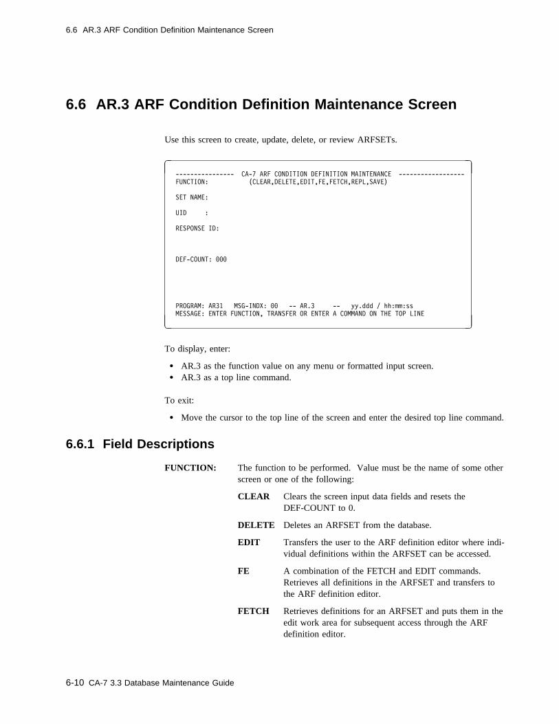
6.6 AR.3 ARF Condition Definition Maintenance Screen
6.6 AR.3 ARF Condition Definition Maintenance Screen
Use this screen to create, update, delete, or review ARFSETs.
� � ---------------- CA-7 ARF CONDITION DEFINITION MAINTENANCE ------------------
FUNCTION: (CLEAR,DELETE,EDIT,FE,FETCH,REPL,SAVE)
SET NAME:
UID :
RESPONSE ID:
DEF-COUNT: ���
PROGRAM: AR31 MSG-INDX: �� -- AR.3 -- yy.ddd / hh:mm:ss
MESSAGE: ENTER FUNCTION, TRANSFER OR ENTER A COMMAND ON THE TOP LINE
( )
To display, enter:
� AR.3 as the function value on any menu or formatted input screen.� AR.3 as a top line command.
To exit:
� Move the cursor to the top line of the screen and enter the desired top line command.
6.6.1 Field Descriptions
FUNCTION: The function to be performed. Value must be the name of some otherscreen or one of the following:
CLEAR Clears the screen input data fields and resets theDEF-COUNT to 0.
DELETE Deletes an ARFSET from the database.
EDIT Transfers the user to the ARF definition editor where indi-vidual definitions within the ARFSET can be accessed.
FE A combination of the FETCH and EDIT commands.Retrieves all definitions in the ARFSET and transfers tothe ARF definition editor.
FETCH Retrieves definitions for an ARFSET and puts them in theedit work area for subsequent access through the ARFdefinition editor.
6-10 CA-7 3.3 Database Maintenance Guide

6.6 AR.3 ARF Condition Definition Maintenance Screen
REPL Replaces the existing ARFSET on the database.
SAVE Adds a new ARFSET to the database.
Required: YesBatch keyword: Positional parameter
SET NAME: The required name of the ARFSET that is being defined.
Size/Type: 1 to 8 alphanumeric charactersRequired: YesBatch keyword: SET
UID: The required CA-7 user security identification.
Size/Type: 1 to 3 numeric characters from 0 to 255Required: YesBatch keyword: UID
RESPONSE ID: The ID that will be used during ARF recovery. ARF uses an internalCA-7 terminal to process any commands that are needed for ARFrecovery. This ID must have the authority to issue any commandsthat the ARF recovery sequence implies. For example, if theARFSET contains a JC definition that has a final disposition ofRESTART, then the RESPONSE ID will be used to issue aRESTART command for the job.
Size/Type: 1 to 8 alphanumeric characters (Maximum lengthallowable may vary depending on the external secu-rity package used, if any)
Required: YesBatch keyword: RESPONDR
DEF-COUNT: A display of the number of definitions that are in the ARF edit workfile.
Chapter 6. Automated Recovery Facility 6-11

6.7 ARF Condition Definition Edit Screen
6.7 ARF Condition Definition Edit Screen
Use this screen to create, update, delete, or review individual definitions in an ARFSET.
� � ---------------------------- ARF CONDITION EDIT ----------------------------
FUNCTION: (ADD,DELETE,EXIT,FORMAT,LIST,REPL,SAVE,SR,SS) DEFCT: ��
TYPE: SYS EQ C SID EQ � RSTC GE � EM EQ C DEFID:
FROM: �1�11975 ���1 TO: 12312�74 2359
JC, SC TST: STEP EQ C PROC EQ C PGM EQ C
CC/ABENDS : ??? GE ���� __ ??? GE ���� __ ??? GE ���� __
??? GE ���� __ ??? GE ���� __ ??? GE ����
EC, EE, IS, LB, LE, LS TST:
RO: GE DATE: TIME: AO: ? INT/ADJ:
RESPONSES:
1:
2:
3:
4:
5:
6:
7:
FINAL -- DISP : N CA-11?: N BYPGDG: N USAGE: PROCESS: CC:
START : END :
PROGRAM: AR32 MSG-INDX: �� -- AR.3.1 -- yy.ddd / hh:mm:ss
MESSAGE: ENTER FUNCTION, TRANSFER OR ENTER A COMMAND ON THE TOP LINE
( )
To display, enter:
� EDIT as the function on the AR.3 screen.
To exit:
� Enter EXIT in the function field.
� Move the cursor to the top line of the screen and enter the desired top line command.
6-12 CA-7 3.3 Database Maintenance Guide
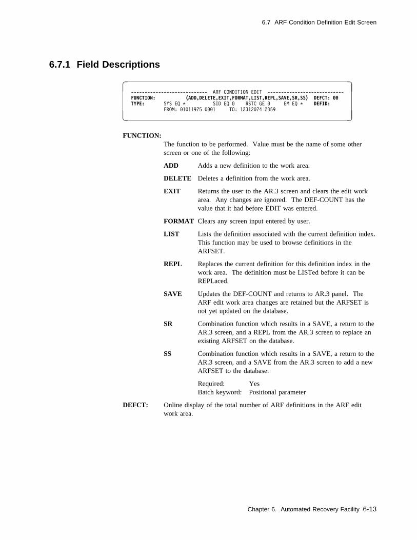
6.7 ARF Condition Definition Edit Screen
6.7.1 Field Descriptions
� � ---------------------------- ARF CONDITION EDIT ----------------------------
FUNCTION: (ADD,DELETE,EXIT,FORMAT,LIST,REPL,SAVE,SR,SS) DEFCT: �� TYPE: SYS EQ C SID EQ � RSTC GE � EM EQ C DEFID:
FROM: �1�11975 ���1 TO: 12312�74 2359
( )
FUNCTION:The function to be performed. Value must be the name of some otherscreen or one of the following:
ADD Adds a new definition to the work area.
DELETE Deletes a definition from the work area.
EXIT Returns the user to the AR.3 screen and clears the edit workarea. Any changes are ignored. The DEF-COUNT has thevalue that it had before EDIT was entered.
FORMAT Clears any screen input entered by user.
LIST Lists the definition associated with the current definition index.This function may be used to browse definitions in theARFSET.
REPL Replaces the current definition for this definition index in thework area. The definition must be LISTed before it can beREPLaced.
SAVE Updates the DEF-COUNT and returns to AR.3 panel. TheARF edit work area changes are retained but the ARFSET isnot yet updated on the database.
SR Combination function which results in a SAVE, a return to theAR.3 screen, and a REPL from the AR.3 screen to replace anexisting ARFSET on the database.
SS Combination function which results in a SAVE, a return to theAR.3 screen, and a SAVE from the AR.3 screen to add a newARFSET to the database.
Required: YesBatch keyword: Positional parameter
DEFCT: Online display of the total number of ARF definitions in the ARF editwork area.
Chapter 6. Automated Recovery Facility 6-13
6.7 ARF Condition Definition Edit Screen
TYPE: Specifies the type of ARF exception condition to be defined. This param-eter is required and the value must be one of the following:
EC Specifies an elapsed time check at normal job completion.
EE Specifies an elapsed time check during job execution.
IS Specifies a test of the date and time just prior to job submission. Ifan exception is detected, the job is requeued prior to executing ARFresponses.
JC Specifies a test for an exception condition based on completion codesto be executed when the job completes.
Note: Tests for job completion are made at each step completion.However, ARF does not respond to a job completion until thejob ends. In the event that several job completion criteria aremet, the responses associated with the lowest definition indexare executed. Only one job completion condition occurs fora given job.
LA Specifies an exception condition results when CA-7 initially promptsfor a late condition. Note that no type specific tests are defined forthe LA exception.
LB Specifies a test to determine whether the job is to be regarded latewhen the job begins.
LE Specifies a test to determine whether the job is to be regarded latewhen the job ends.
LS Specifies a test to determine whether the job is to be regarded latewhen the job is submitted.
SC Specifies a test for an exception condition based on completion codesto be executed when the specified step completes.
Required: YesBatch keyword: TYPE
DEFID: An index which uniquely specifies this definition within the ARFSET.
Size/Type: 1 to 3 decimal charactersValid values 1-255
Required: YesBatch keyword: DEFID
6-14 CA-7 3.3 Database Maintenance Guide
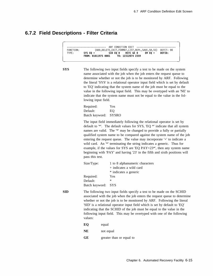
6.7 ARF Condition Definition Edit Screen
6.7.2 Field Descriptions - Filter Criteria
� � ---------------------------- ARF CONDITION EDIT ----------------------------
FUNCTION: (ADD,DELETE,EXIT,FORMAT,LIST,REPL,SAVE,SR,SS) DEFCT: ��
TYPE: SYS EQ � SID EQ � RSTC GE � EM EQ � DEFID:FROM: �1�11975 ���1 TO: 12312�74 2359
( )
SYS The following two input fields specify a test to be made on the systemname associated with the job when the job enters the request queue todetermine whether or not the job is to be monitored by ARF. Followingthe literal 'SYS' is a relational operator input field which is set by defaultto 'EQ' indicating that the system name of the job must be equal to thevalue in the following input field. This may be overtyped with an 'NE' toindicate that the system name must not be equal to the value in the fol-lowing input field.
Required: YesDefault: EQBatch keyword: SYSRO
The input field immediately following the relational operator is set bydefault to '*'. The default values for SYS, 'EQ *' indicate that all systemnames are valid. The '*' may be changed to provide a fully or partiallyqualified system name to be compared against the system name of the jobentering the request queue. The value may incorporate '+' to indicate awild card. An '*' terminating the string indicates a generic. Thus forexample, if the values for SYS are 'EQ PAY+23*', then any system namebeginning with 'PAY' and having '23' in the fifth and sixth positions willpass this test.
Size/Type: 1 to 8 alphanumeric characters+ indicates a wild card* indicates a generic
Required: YesDefault: *Batch keyword: SYS
SID The following two input fields specify a test to be made on the SCHIDassociated with the job when the job enters the request queue to determinewhether or not the job is to be monitored by ARF. Following the literal'SID' is a relational operator input field which is set by default to 'EQ'indicating that the SCHID of the job must be equal to the value in thefollowing input field. This may be overtyped with one of the followingvalues:
EQ equal
NE not equal
GE greater than or equal to
Chapter 6. Automated Recovery Facility 6-15

6.7 ARF Condition Definition Edit Screen
GT greater than
LE less than or equal to
LT less than
The SCHID of the job entering the request queue will be compared to thevalue in the input field following the relational operator. If the resultingstatement is true then the test is passed.
Required: YesDefault: EQBatch keyword: SIDRO
The input field immediately following the relational operator is set bydefault to '0'. The default values for SID, 'EQ 0' indicate that all SCHIDsare valid. The '0' may be changed to provide a fully qualified SCHIDvalue from 001-255 to be compared against the SCHID of the job enteringthe request queue.
Size/Type: 1 to 3 decimal characters from 0 to 255Required: YesDefault: 0 (a value of 0 refers to ALL SCHIDs)Batch keyword: SID
RSTC The following two input fields specify a test to be made on the restartcount of the job to determine whether or not the job is to be monitored byARF. Following the literal 'RSTC' is a relational operator input fieldwhich is set by default to 'GE' indicating that the restart count of the jobmust be greater than or equal to the value in the following input field.This may be overtyped with one of the following values:
NE not equal
GE greater than or equal to
EQ equal
GT greater than
LE less than or equal to
LT less than
The restart count of the job will be compared to the value in the input fieldfollowing the relational operator. If the resulting statement is true then thetest is passed.
Required: YesDefault: GEBatch keyword: RSTRO
The input field immediately following the relational operator is set bydefault to '0'. The default values for RSTC, 'GE 0' indicate that any restartcount is valid. The '0' may be changed to provide a fully qualified decimalvalue from 0 to 999 to be compared against the restart count of the job tobe considered for ARF monitoring.
6-16 CA-7 3.3 Database Maintenance Guide
6.7 ARF Condition Definition Edit Screen
Size/Type: 1 to 3 decimal characters from 0 to 999Required: YesDefault: 0Batch keyword: RST
EM The following two input fields specify a test to be made on the entry modeof the job when the job enters the request queue to determine whether thejob is to be monitored by ARF. Following the literal 'EM' is a relationaloperator input field which is set by default to 'EQ' indicating that the entrymode of the job must be equal to the value in the following input field.This may be overtyped with an 'NE' to indicate that the entry mode mustnot be equal to the value in the following input field.
Required: YesDefault: EQBatch keyword: EMRO
The input field immediately following the relational operator is set bydefault to '*'. The default values for EM, 'EQ *' indicate that all entrymodes are valid. The '*' may be changed to provide a fully qualified entrymode designation to be compared against the entry mode of the jobentering the request queue. Entry mode designations valid in this field are:
DEMD Job entered through a DEMAND command
RUN Job entered through a RUN command
SSCN Job entered through a schedule scan
JTRG Job entered through a job trigger
DTRG Job entered through a DSN trigger
NTRG Job entered through a network trigger
PSCH Job entered through personal scheduling
Required: YesDefault: * (all entry modes)Batch keyword: EM
FROM Two input fields used to specify a date and time that is compared againstthe date and time when the job enters the request queue. In order to passthe test, the queue entry date and time must be greater than the date andtime specified here.
FROM Date
Size/Type: 8 numeric character positions in MMDDYYYY format.Valid range from 01011975 to 12312074. You can alsouse one of the reserved words in Table 6-1 onpage 6-37.
Required: YesDefault: 01011975Batch keyword: FROMD
Chapter 6. Automated Recovery Facility 6-17

6.7 ARF Condition Definition Edit Screen
FROM Time
Size/Type: 4 character positions in HHMM format. Valid rangefrom 0000 to 2359.
Required: YesDefault: 0001 (1 minute past midnight)Batch keyword: FROMT
TO Two input fields used to specify a date and time that is compared againstthe date and time when the job enters the request queue. To pass the test,the queue entry date and time must be less than the date and time specifiedhere.
TO Date
Size/Type: 8 character positions in MMDDYYYY format. Validrange from 01011975 to 12312074. You can also useone of the reserved words in Table 6-1 on page 6-37.
Required: YesDefault: 12312074Batch keyword: TOD
TO Time
Size/Type: 4 character positions in HHMM format. Valid rangefrom 0000 to 2359.
Required: YesDefault: 2359 (11:59 PM)Batch keyword: TOT
6-18 CA-7 3.3 Database Maintenance Guide
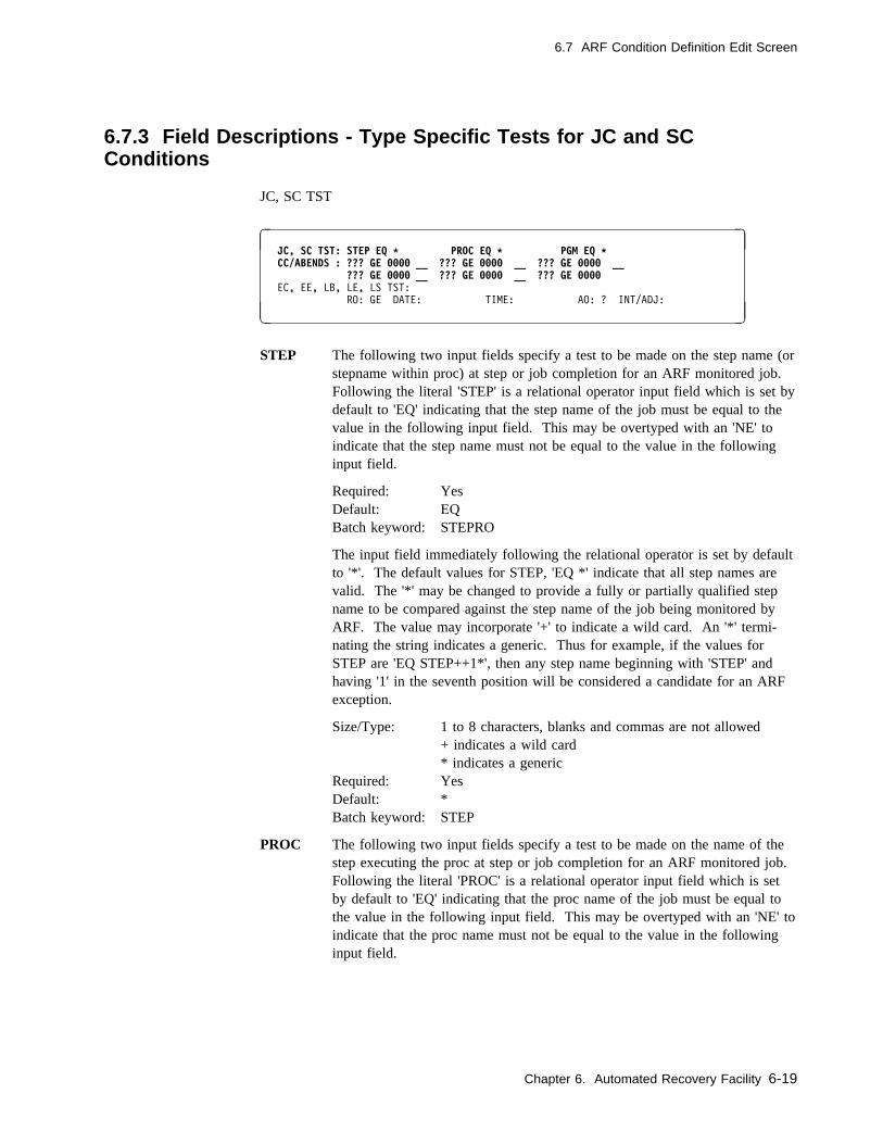
6.7 ARF Condition Definition Edit Screen
6.7.3 Field Descriptions - Type Specific Tests for JC and SCConditions
JC, SC TST
� � JC, SC TST: STEP EQ � PROC EQ � PGM EQ � CC/ABENDS : ??? GE ���� __ ??? GE ���� __ ??? GE ���� __
??? GE ���� __ ??? GE ���� __ ??? GE ���� EC, EE, LB, LE, LS TST:
RO: GE DATE: TIME: AO: ? INT/ADJ:
( )
STEP The following two input fields specify a test to be made on the step name (orstepname within proc) at step or job completion for an ARF monitored job.Following the literal 'STEP' is a relational operator input field which is set bydefault to 'EQ' indicating that the step name of the job must be equal to thevalue in the following input field. This may be overtyped with an 'NE' toindicate that the step name must not be equal to the value in the followinginput field.
Required: YesDefault: EQBatch keyword: STEPRO
The input field immediately following the relational operator is set by defaultto '*'. The default values for STEP, 'EQ *' indicate that all step names arevalid. The '*' may be changed to provide a fully or partially qualified stepname to be compared against the step name of the job being monitored byARF. The value may incorporate '+' to indicate a wild card. An '*' termi-nating the string indicates a generic. Thus for example, if the values forSTEP are 'EQ STEP++1*', then any step name beginning with 'STEP' andhaving '1' in the seventh position will be considered a candidate for an ARFexception.
Size/Type: 1 to 8 characters, blanks and commas are not allowed+ indicates a wild card* indicates a generic
Required: YesDefault: *Batch keyword: STEP
PROC The following two input fields specify a test to be made on the name of thestep executing the proc at step or job completion for an ARF monitored job.Following the literal 'PROC' is a relational operator input field which is setby default to 'EQ' indicating that the proc name of the job must be equal tothe value in the following input field. This may be overtyped with an 'NE' toindicate that the proc name must not be equal to the value in the followinginput field.
Chapter 6. Automated Recovery Facility 6-19

6.7 ARF Condition Definition Edit Screen
Required: YesDefault: EQBatch keyword: PROCRO
The input field immediately following the relational operator is set by defaultto '*'. The default values for PROC, 'EQ *' indicate that all proc names arevalid. The '*' may be changed to provide a fully or partially qualified procname to be compared against the proc name of the job being monitored byARF. The value may incorporate '+' to indicate a wild card. An '*' termi-nating the string indicates a generic. Thus for example, if the values forPROC are 'EQ PROC++1*', then any proc name beginning with 'PROC' andhaving '1' in the seventh position will be considered a candidate for an ARFexception.
Size/Type: 1 to 8 characters, commas and blanks are not allowed+ indicates a wild card* indicates a generic
Required: YesDefault: *Batch keyword: PROC
PGM The following two input fields specify a test to be made on the programname at step or job completion for an ARF monitored job. Following theliteral 'PGM' is a relational operator input field which is set by default to 'EQ'indicating that the program name of the job must be equal to the value in thefollowing input field. This may be overtyped with an 'NE' to indicate thatthe program name must not be equal to the value in the following input field.
Required: YesDefault: EQBatch keyword: PGMRO
The input field immediately following the relational operator is set by defaultto '*'. The default values for PGM, 'EQ *' indicate that all program namesare valid. The '*' may be changed to provide a fully or partially qualifiedprogram name to be compared against the program name of the job beingmonitored by ARF. The value may incorporate '+' to indicate a wild card.An '*' terminating the string indicates a generic. Thus for example, if thevalues for PGM are 'EQ PROG++1*', then any program name beginning with'PROG' and having '1' in the seventh position will be considered a candidatefor an ARF exception.
Size/Type: 1 to 8 characters, commas and blanks are not allowed+ indicates a wild card* indicates a generic
Required: YesDefault: *Batch keyword: PGM
6-20 CA-7 3.3 Database Maintenance Guide

6.7 ARF Condition Definition Edit Screen
CC/ABENDSUp to six tests of completion codes may be coded here and joined byBoolean operators to create complex completion code tests.
The first input field in a completion code test allows specification of theformat of the completion code test. Overtype this field with one of the fol-lowing values in order to define a completion code test:
??? Indicates no completion code test.
SYS The completion code to be tested is a system abend code.
USR The completion code to be tested is a user abend code.
CC The completion code to be tested is a condition code.
FL A test for a flush condition is indicated. If this value is used, thecorresponding completion code field is ignored.
JCL A test for a JCL error is indicated. If this value is used, thecorresponding completion code is ignored.
Required: NoDefault: ??? (indicates no test)Batch keyword: FMT1,FMT2,FMT3,FMT4,FMT5,FMT6
The second input field in a completion code test allows specification of therelational operator to be used in the completion code test. The default is'GE'. This may be overtyped with one of the following values:
NE not equal
GE greater than or equal to
EQ equal
GT greater than
LE less than or equal to
LT less than
Required: No, unless the first input has a value other than ???Default: GEBatch keyword: RO1,RO2,RO3,RO4,RO5,RO6
Chapter 6. Automated Recovery Facility 6-21
6.7 ARF Condition Definition Edit Screen
The third input field in a completion code test allows specification of thecompletion code value to be used in a completion code test. The default is'000'. This value may be overtyped with a character value appropriate for theformat of the completion code test. For example, if the first input field in thetest contains 'SYS' indicating a system abend, then a valid completion codevalue might be 'E37'. The completion code value may contain '+' to indicatea wild card and '*' for generics. For example, the following completion codetest would cause an ARF exception to be recognized for any system abendending in '37': 'SYS EQ +37'.
Size/Type: For SYS, 3 valid hexadecimal charactersFor USR and CC, 1 to 4 decimal characters
Required: No, unless the first input has a value other than ???Default: 000Batch keyword: VAL1,VAL2,VAL3,VAL4,VAL5,VAL6
Completion code tests may be joined using the following logical connectives:
& Indicates the tests are to be 'and'ed
/ Indicates the tests are to be 'or'ed
Required: No, unless tests are to be joinedDefault: __ indicating no connectiveBatch keyword: LO1,LO2,LO3,LO4,LO5
6-22 CA-7 3.3 Database Maintenance Guide
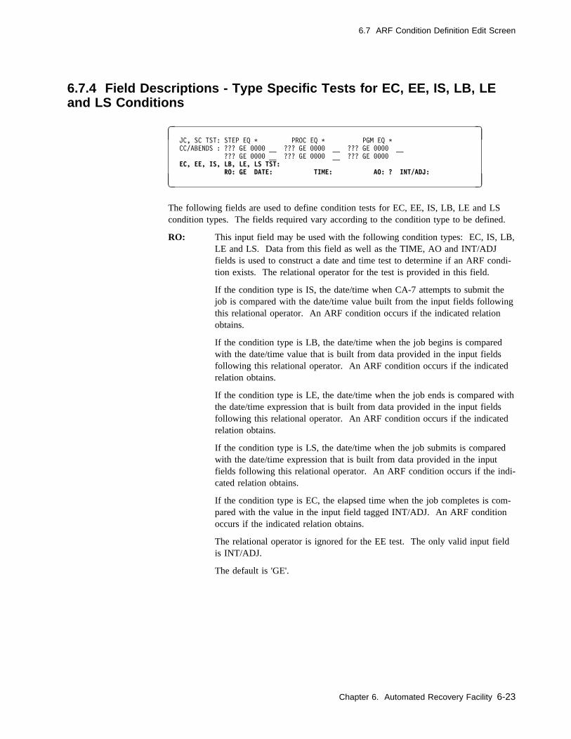
6.7 ARF Condition Definition Edit Screen
6.7.4 Field Descriptions - Type Specific Tests for EC, EE, IS, LB, LEand LS Conditions
� � JC, SC TST: STEP EQ C PROC EQ C PGM EQ C
CC/ABENDS : ??? GE ���� __ ??? GE ���� __ ??? GE ���� __
??? GE ���� __ ??? GE ���� __ ??? GE ����
EC, EE, IS, LB, LE, LS TST:RO: GE DATE: TIME: AO: ? INT/ADJ:
( )
The following fields are used to define condition tests for EC, EE, IS, LB, LE and LScondition types. The fields required vary according to the condition type to be defined.
RO: This input field may be used with the following condition types: EC, IS, LB,LE and LS. Data from this field as well as the TIME, AO and INT/ADJfields is used to construct a date and time test to determine if an ARF condi-tion exists. The relational operator for the test is provided in this field.
If the condition type is IS, the date/time when CA-7 attempts to submit thejob is compared with the date/time value built from the input fields followingthis relational operator. An ARF condition occurs if the indicated relationobtains.
If the condition type is LB, the date/time when the job begins is comparedwith the date/time value that is built from data provided in the input fieldsfollowing this relational operator. An ARF condition occurs if the indicatedrelation obtains.
If the condition type is LE, the date/time when the job ends is compared withthe date/time expression that is built from data provided in the input fieldsfollowing this relational operator. An ARF condition occurs if the indicatedrelation obtains.
If the condition type is LS, the date/time when the job submits is comparedwith the date/time expression that is built from data provided in the inputfields following this relational operator. An ARF condition occurs if the indi-cated relation obtains.
If the condition type is EC, the elapsed time when the job completes is com-pared with the value in the input field tagged INT/ADJ. An ARF conditionoccurs if the indicated relation obtains.
The relational operator is ignored for the EE test. The only valid input fieldis INT/ADJ.
The default is 'GE'.
Chapter 6. Automated Recovery Facility 6-23

6.7 ARF Condition Definition Edit Screen
This may be overtyped with one of the following values:
NE not equal
GE greater than or equal to
GT greater than
EQ equal
LE less than or equal to
LT less than
Required: Required for EC, IS, LB, LE and LS condition types. Itshould not be specified for any other condition type.
Default: GEBatch keyword: TRO
DATE: This input field may be used with the following condition types: IS, LB, LEand LS. Data from this field as well as the TIME, AO, and INT/ADJ fieldsis used to construct a date and time that is used in a comparison to determineif an ARF condition exists. An ARF condition occurs if the relation indi-cated by the RO value obtains.
If the condition type is IS, the date/time when CA-7 attempts to submit thejob is compared with the date/time expression specified here.
If the condition type is LB, the date/time when the job begins is comparedwith the date/time expression specified here.
If the condition type is LE, the date/time when the job ends is compared withthe date/time expression that is specified here.
If the condition type is LS, the date/time when the job submits is comparedwith the date/time expression that is specified here.
Size/Type: 8 character positions in MMDDYYYY format. Valid rangefrom 01011975 to 12312074. You can also use one of thereserved words in Table 6-1 on page 6-37.
Required: Required for IS, LB, LE and LS condition types. It shouldnot be specified for any other condition types.
Batch keyword: TDAT
6-24 CA-7 3.3 Database Maintenance Guide

6.7 ARF Condition Definition Edit Screen
TIME: This input field may be used with the following condition types: IS, LB, LEand LS. Data from this field as well as the DATE, AO and INT/ADJ fieldsis used to construct a date and time that is used in a comparison to determineif an ARF condition exists.
If the condition type is IS, the date/time when CA-7 attempts to submit thejob is compared with the date/time expression specified here.
If the condition type is LB, the date/time when the job begins is comparedwith the date/time expression specified here.
If the condition type is LE, the date/time when the job ends is compared withthe date/time expression that is specified here.
If the condition type is LS, the date/time when the job submits is comparedwith the date/time expression that is specified here.
Size/Type: 4 character positions in HHMM format. Valid range from0000 to 2359. You can also use one of the reserved wordsin Table 6-1 on page 6-37.
Required: Required for IS, LB, LE and LS condition types. It shouldnot be specified for any other condition types.
Batch keyword: TTIM
AO: This input field may be used with the following condition types: IS, LB, LEand LS. Data from this field as well as the DATE, TIME and INT/ADJfields is used to construct a date and time that is used in a comparison todetermine if an ARF condition exists.
Data from this field along with data in the INT/ADJ field is used to adjustthe date/time value provided in the DATE and TIME fields. If the incrementused as an adjustment is to be added, use '+', if it is to be subtracted, use '-'.
If the condition type is IS, the date/time when CA-7 attempts to submit thejob is compared with the date/time expression specified here.
If the condition type is LB, the date/time when the job begins is comparedwith the date/time expression specified here.
If the condition type is LE, the date/time when the job ends is compared withthe date/time expression that is specified here.
If the condition type is LS, the date/time when the job submits is comparedwith the date/time expression that is specified here.
Size/Type: 1 position. Allowable values are '+' or '-'.Required: Only allowable on IS, LB, LE and LS condition types. It
should not be specified for any other condition types. Itshould only be used if an adjustment value is provided inthe INT/ADJ field.
Batch keyword: TAO
Chapter 6. Automated Recovery Facility 6-25

6.7 ARF Condition Definition Edit Screen
INT/ADJ: This input field may be used with the following condition types: EC, EE, IS,LB, LE and LS. Data from this field may be interpreted as an adjustment toa date and time already specified; this is its meaning if the condition type isLB, LE or LS. If the condition type is EC or EE, then the value in this fieldis interpreted as an elapsed time interval.
The value of this field should be should be specified in HHMM format, andis valid within ± 1 minute.
Size/Type: 4 character positions in HHMM format. Valid range from0000 to 2359. You can also use one of the reserved wordsin Table 6-1 on page 6-37.
Required: Required for EE and ECAllowed for IS, LB, LE, and LS.It should not be specified for any other condition types.
Batch keyword: INT
6-26 CA-7 3.3 Database Maintenance Guide
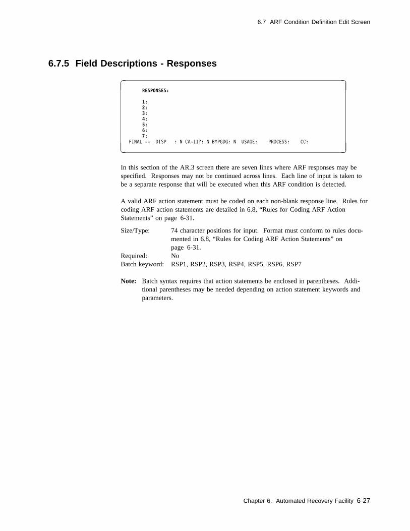
6.7 ARF Condition Definition Edit Screen
6.7.5 Field Descriptions - Responses
� � RESPONSES:
1: 2: 3: 4: 5: 6: 7: FINAL -- DISP : N CA-11?: N BYPGDG: N USAGE: PROCESS: CC:
( )
In this section of the AR.3 screen there are seven lines where ARF responses may bespecified. Responses may not be continued across lines. Each line of input is taken tobe a separate response that will be executed when this ARF condition is detected.
A valid ARF action statement must be coded on each non-blank response line. Rules forcoding ARF action statements are detailed in 6.8, “Rules for Coding ARF ActionStatements” on page 6-31.
Size/Type: 74 character positions for input. Format must conform to rules docu-mented in 6.8, “Rules for Coding ARF Action Statements” onpage 6-31.
Required: NoBatch keyword: RSP1, RSP2, RSP3, RSP4, RSP5, RSP6, RSP7
Note: Batch syntax requires that action statements be enclosed in parentheses. Addi-tional parentheses may be needed depending on action statement keywords andparameters.
Chapter 6. Automated Recovery Facility 6-27
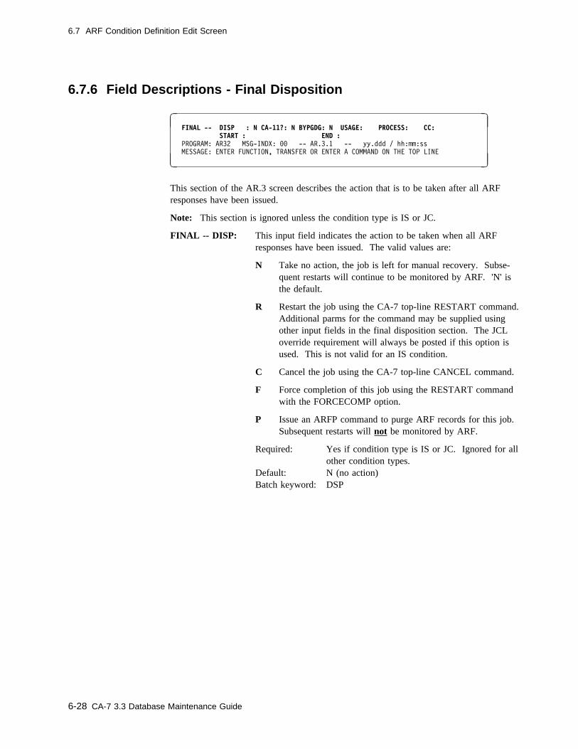
6.7 ARF Condition Definition Edit Screen
6.7.6 Field Descriptions - Final Disposition
� � FINAL -- DISP : N CA-11?: N BYPGDG: N USAGE: PROCESS: CC: START : END : PROGRAM: AR32 MSG-INDX: �� -- AR.3.1 -- yy.ddd / hh:mm:ss
MESSAGE: ENTER FUNCTION, TRANSFER OR ENTER A COMMAND ON THE TOP LINE
( )
This section of the AR.3 screen describes the action that is to be taken after all ARFresponses have been issued.
Note: This section is ignored unless the condition type is IS or JC.
FINAL -- DISP: This input field indicates the action to be taken when all ARFresponses have been issued. The valid values are:
N Take no action, the job is left for manual recovery. Subse-quent restarts will continue to be monitored by ARF. 'N' isthe default.
R Restart the job using the CA-7 top-line RESTART command.Additional parms for the command may be supplied usingother input fields in the final disposition section. The JCLoverride requirement will always be posted if this option isused. This is not valid for an IS condition.
C Cancel the job using the CA-7 top-line CANCEL command.
F Force completion of this job using the RESTART commandwith the FORCECOMP option.
P Issue an ARFP command to purge ARF records for this job.Subsequent restarts will not be monitored by ARF.
Required: Yes if condition type is IS or JC. Ignored for allother condition types.
Default: N (no action)Batch keyword: DSP
6-28 CA-7 3.3 Database Maintenance Guide
6.7 ARF Condition Definition Edit Screen
CA-11?: This input field indicates whether CA-11 is to be used for restart.The valid values are:
N No, CA-11 is not to be used for restart. This is the default.
Y Yes, CA-11 is to be used for restart. Other input values inthe final disposition section may be relevant.
Required: Required only if CA-11 is to be used for restart.Default: N (CA-11 not used)Batch keyword: CA11
BYPGDG: This input field indicates the value on the RESTART command.See the documentation on the RESTART command for furtherdetails.
Valid values are:
C CA-11 to accept GDG bias resolution according to the MVScatalog (CAT option of CA-11).
N This is the default. CA-11 should NOT bypass GDG logic onrestart.
V CA-11 to verify that the GDG bias resolution recorded in theCMT agrees with the MVS catalog (VER option of CA-11).
Y Yes, CA-11 should bypass GDG logic on restart.
Required: NODefault: N (CA-11 will not bypass GDG logic)Batch keyword: BYPGDG
USAGE: Used to supply the value of the USAGE parameter to be used onthe RESTART command. See CA-11 documentation for values.This option honored only if CA-11 used and CA-7 is inserting theRMS step. See the documentation on the INSERT-RMS field ofthe DB.1 screen and on the RESTART command for further details.
Size/Type: 1 alphanumeric characterRequired: NoBatch keyword: USAGE
PROCESS: Used to supply the value of the PROCESS parameter to be used onthe RESTART command. This option honored only if CA-11 usedand CA-7 is inserting the RMS step. Valid values are F, P, S, N, Oor R. See the documentation on the INSERT-RMS field of theDB.1 screen and on the RESTART command for further details.
Size/Type: 1 alphanumeric characterRequired: NoBatch keyword: PROCESS
Chapter 6. Automated Recovery Facility 6-29
6.7 ARF Condition Definition Edit Screen
CC Used to supply the value of the CONDCD parameter to be used onthe RESTART command. This option honored only if CA-11 usedand CA-7 is inserting the RMS step. See the documentation on theINSERT-RMS field of the DB.1 screen and on the RESTARTcommand for further details.
Size/Type: 1 to 4 alphanumeric characters from 0-4095Required: NoBatch keyword: CC
START: Used to supply values of the PROCSTRT and STPSTRT parameterson the RESTART command. This option honored only if CA-11used.
The format of the START value is 'procstep.step' where 'procstep' isthe value of the PROCSTRT keyword and 'step' is the value of theSTPSTRT keyword. If the value of this field does not contain a '.'then it is assumed that the input applies only to the STPSTRTkeyword. If the step number is used, then PROCSTRT cannot beused.
See the documentation on the RESTART command for furtherdetails.
Size/Type: 1 to 17 alphanumeric characters. If procstep ref-erence is provided, a '.' must separate procstepname and step name. You should validate thisvalue prior to use to ensure that the steps namedhere are used by the job that uses this ARFSET.
Required: NoBatch keyword: START
END: Used to supply values of the PROCEND and STPEND parameterson the RESTART command. This option honored only if CA-11used.
The format of the END value is 'procstep.step' where 'procstep' isthe value of the PROCEND keyword and 'step' is the value of theSTPEND keyword. If the value of this field does not contain a '.'then it is assumed that the input applies only to the STPENDkeyword. If the step number is used, then PROCEND cannot beused.
See the documentation on the RESTART command for furtherdetails.
Size/Type: 1 to 17 alphanumeric characters. If procstep ref-erence is provided, a '.' must separate procstepname and step name. You should validate thisvalue prior to use to ensure that the steps namedhere are used by the job that uses this ARFSET.
Required: NoBatch keyword: END
6-30 CA-7 3.3 Database Maintenance Guide
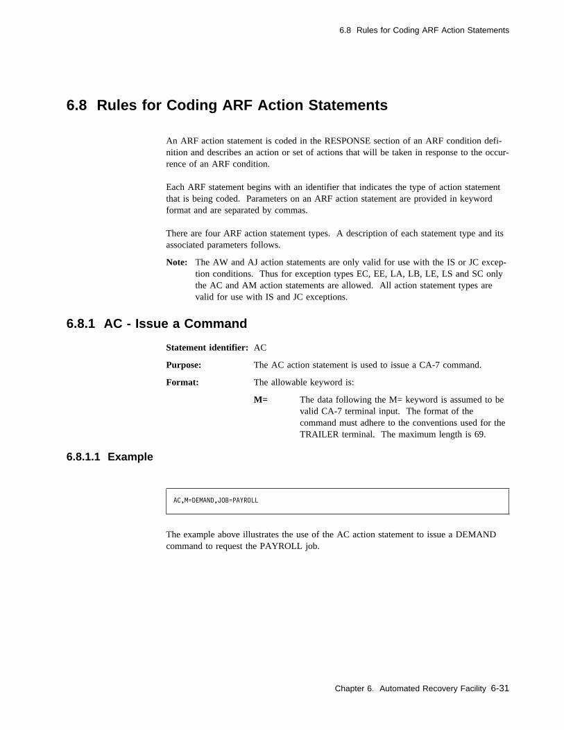
6.8 Rules for Coding ARF Action Statements
6.8 Rules for Coding ARF Action Statements
An ARF action statement is coded in the RESPONSE section of an ARF condition defi-nition and describes an action or set of actions that will be taken in response to the occur-rence of an ARF condition.
Each ARF statement begins with an identifier that indicates the type of action statementthat is being coded. Parameters on an ARF action statement are provided in keywordformat and are separated by commas.
There are four ARF action statement types. A description of each statement type and itsassociated parameters follows.
Note: The AW and AJ action statements are only valid for use with the IS or JC excep-tion conditions. Thus for exception types EC, EE, LA, LB, LE, LS and SC onlythe AC and AM action statements are allowed. All action statement types arevalid for use with IS and JC exceptions.
6.8.1 AC - Issue a Command
Statement identifier: AC
Purpose: The AC action statement is used to issue a CA-7 command.
Format: The allowable keyword is:
M= The data following the M= keyword is assumed to bevalid CA-7 terminal input. The format of thecommand must adhere to the conventions used for theTRAILER terminal. The maximum length is 69.
6.8.1.1 Example
AC,M=DEMAND,JOB=PAYROLL
The example above illustrates the use of the AC action statement to issue a DEMANDcommand to request the PAYROLL job.
Chapter 6. Automated Recovery Facility 6-31
6.8 Rules for Coding ARF Action Statements
6.8.2 AM - Issue a Message
Statement identifier: AM
Purpose: Execution of the AM action statement causes messages to beissued to the MVS console or to a specified TSO user.
Format: The allowable keywords are:
CM= The data following the CM= specifies the communi-cations mode for the message. The following are theacceptable values of CM=:
T Send the messages to the user whose TSO ID isspecified using the U= keyword. The message isnot retained if the specified TSO user is notlogged on.
L Send the messages to the user whose TSO ID isspecified using the U= keyword. If the specifiedTSO user is not logged on, the message will beretained and may be displayed in the next TSOsession.
C Send the messages to the MVS console.
H Send the messages to the MVS console and high-light them.
U= The data following the U= names the TSO user that isto receive the messages. This value is required ifCM=T or CM=L. It is invalid for any other value ofCM. This keyword can also be coded as USER=.
M= The data following the M= specifies the text of amessage that is to be issued. If the text containscommas or keywords (x=y), enclose the entire textstring in parentheses. The maximum length is 60characters.
6-32 CA-7 3.3 Database Maintenance Guide

6.8 Rules for Coding ARF Action Statements
6.8.2.1 Examples
AM,CM=T,U=TSOUSER1,M=HELLO THERE!
The example above illustrates the use of the AM action statement to send the message"HELLO THERE!" to a TSO user.
AM,CM=C,M=HELLO CONSOLE!
The example above illustrates the use of the AM action statement to send the message"HELLO CONSOLE!" to the MVS console.
Chapter 6. Automated Recovery Facility 6-33
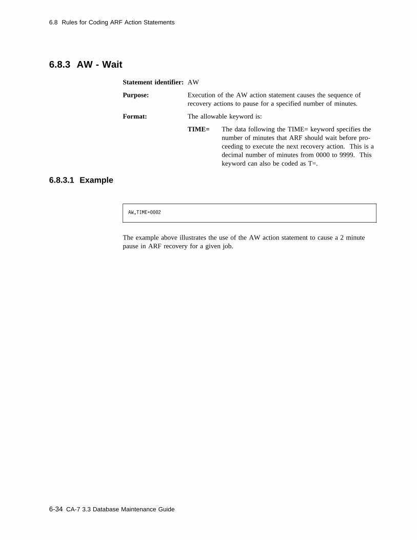
6.8 Rules for Coding ARF Action Statements
6.8.3 AW - Wait
Statement identifier: AW
Purpose: Execution of the AW action statement causes the sequence ofrecovery actions to pause for a specified number of minutes.
Format: The allowable keyword is:
TIME= The data following the TIME= keyword specifies thenumber of minutes that ARF should wait before pro-ceeding to execute the next recovery action. This is adecimal number of minutes from 0000 to 9999. Thiskeyword can also be coded as T=.
6.8.3.1 Example
AW,TIME=���2
The example above illustrates the use of the AW action statement to cause a 2 minutepause in ARF recovery for a given job.
6-34 CA-7 3.3 Database Maintenance Guide
6.8 Rules for Coding ARF Action Statements
6.8.4 AJ - Schedule a Recovery Job
Statement identifier: AJ
Purpose: The AJ action statement is used to schedule a job (known as an'ARFJ' job) to run on behalf of the job that is in recovery. ARFwill not proceed to the next ARF action statement until this actionstatement is considered complete. An AJ action statement is com-plete when the ARFJ job completes successfully or when the spec-ified number of retries is exhausted.
Note: The completion of an ARFJ job does not satisfy require-ments, nor does it cause triggering of other jobs.However, CA-7 tracks the progress of the ARFJ job andrecords its completion status in the run log and in mes-sages to the master station.
Also, ARFSET designations (such as those on the DB.1panel or on #ARF statements in the JCL) are ignored forARFJ jobs. Thus, ARFJ jobs are not monitored for ARFrecovery.
Format: The allowable keywords are:
JOB= The value of this keyword names the job that is to runon behalf of the job that is in recovery. This keywordis required and there is no default.
RETRY= If the ARFJ job does not complete successfully, ARFcan request the job again. The value of the RETRYparameter is the maximum number of times the jobcan be retried. The acceptable values are 0-9. Thedefault value is RETRY=0.
DELAY= If the ARFJ job does not complete successfully, ARFcan request the job again. The value on the DELAYkeyword specifies the number of minutes beforeretrying. This value must be specified as a decimalnumber of minutes from 0 to 9999. The default valueis DELAY=0000.
Chapter 6. Automated Recovery Facility 6-35
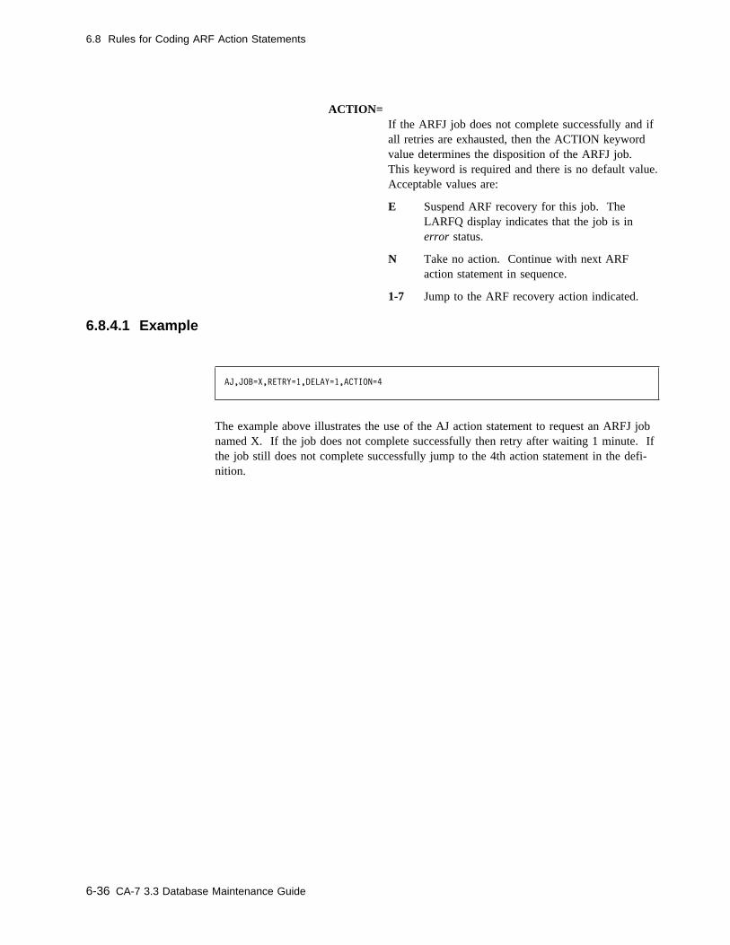
6.8 Rules for Coding ARF Action Statements
ACTION=If the ARFJ job does not complete successfully and ifall retries are exhausted, then the ACTION keywordvalue determines the disposition of the ARFJ job.This keyword is required and there is no default value.Acceptable values are:
E Suspend ARF recovery for this job. TheLARFQ display indicates that the job is inerror status.
N Take no action. Continue with next ARFaction statement in sequence.
1-7 Jump to the ARF recovery action indicated.
6.8.4.1 Example
AJ,JOB=X,RETRY=1,DELAY=1,ACTION=4
The example above illustrates the use of the AJ action statement to request an ARFJ jobnamed X. If the job does not complete successfully then retry after waiting 1 minute. Ifthe job still does not complete successfully jump to the 4th action statement in the defi-nition.
6-36 CA-7 3.3 Database Maintenance Guide
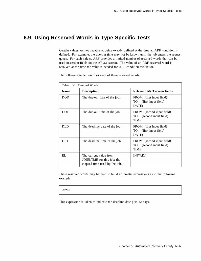
6.9 Using Reserved Words in Type Specific Tests
6.9 Using Reserved Words in Type Specific Tests
Certain values are not capable of being exactly defined at the time an ARF condition isdefined. For example, the due-out time may not be known until the job enters the requestqueue. For such values, ARF provides a limited number of reserved words that can beused in certain fields on the AR.3.1 screen. The value of an ARF reserved word isresolved at the time the value is needed for ARF condition evaluation.
The following table describes each of these reserved words:
These reserved words may be used to build arithmetic expressions as in the followingexample:
Table 6-1. Reserved Words
Name Description Relevant AR.3 screen fields
DOD The due-out date of the job. FROM: (first input field)TO: (first input field)DATE:
DOT The due-out time of the job. FROM: (second input field)TO: (second input field)TIME:
DLD The deadline date of the job. FROM: (first input field)TO: (first input field)DATE:
DLT The deadline time of the job. FROM: (second input field)TO: (second input field)TIME:
EL The current value fromJQJELTME for this job; theelapsed time used by the job.
INT/ADJ:
DLD+12
This expression is taken to indicate the deadline date plus 12 days.
Chapter 6. Automated Recovery Facility 6-37
6.9 Using Reserved Words in Type Specific Tests
Syntax: If used in an arithmetic expression, the reserved word must be followed imme-diately (no spaces) by an arithmetic operator (either + or -). If an arithmetic operator ispresent, it must be followed immediately (no spaces) by a decimal numeric value (up to 4digits). The value of the reserved word will be incremented or decremented by theamount specified. The unit of the increment/decrement depends on the reserved word.For example, if the expression is DOT+0020, this is interpreted as the due-out time plus20 minutes.
6-38 CA-7 3.3 Database Maintenance Guide
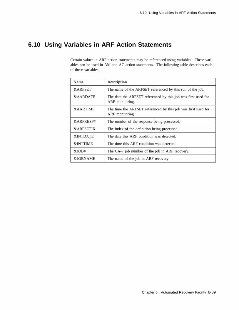
6.10 Using Variables in ARF Action Statements
6.10 Using Variables in ARF Action Statements
Certain values in ARF action statements may be referenced using variables. These vari-ables can be used in AM and AC action statements. The following table describes eachof these variables:
Name Description
&ARFSET The name of the ARFSET referenced by this run of the job.
&AARDATE The date the ARFSET referenced by this job was first used forARF monitoring.
&AARTIME The time the ARFSET referenced by this job was first used forARF monitoring.
&ARFRESP# The number of the response being processed.
&ARFSETIX The index of the definition being processed.
&INTDATE The date this ARF condition was detected.
&INTTIME The time this ARF condition was detected.
&JOB# The CA-7 job number of the job in ARF recovery.
&JOBNAME The name of the job in ARF recovery.
Chapter 6. Automated Recovery Facility 6-39
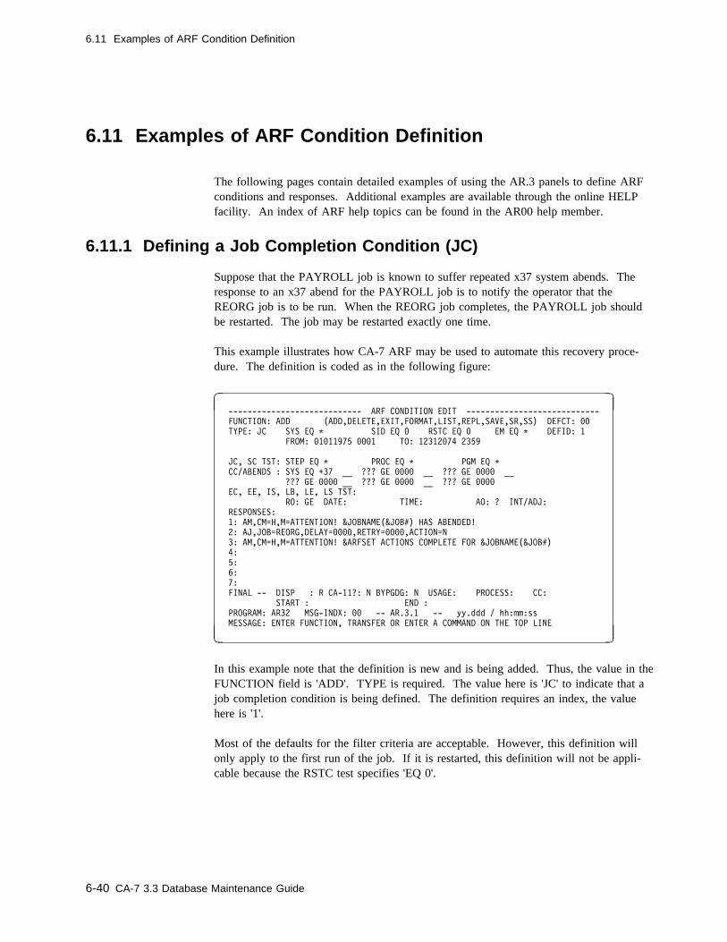
6.11 Examples of ARF Condition Definition
6.11 Examples of ARF Condition Definition
The following pages contain detailed examples of using the AR.3 panels to define ARFconditions and responses. Additional examples are available through the online HELPfacility. An index of ARF help topics can be found in the AR00 help member.
6.11.1 Defining a Job Completion Condition (JC)
Suppose that the PAYROLL job is known to suffer repeated x37 system abends. Theresponse to an x37 abend for the PAYROLL job is to notify the operator that theREORG job is to be run. When the REORG job completes, the PAYROLL job shouldbe restarted. The job may be restarted exactly one time.
This example illustrates how CA-7 ARF may be used to automate this recovery proce-dure. The definition is coded as in the following figure:
� � ---------------------------- ARF CONDITION EDIT ----------------------------
FUNCTION: ADD (ADD,DELETE,EXIT,FORMAT,LIST,REPL,SAVE,SR,SS) DEFCT: ��
TYPE: JC SYS EQ C SID EQ � RSTC EQ � EM EQ C DEFID: 1
FROM: �1�11975 ���1 TO: 12312�74 2359
JC, SC TST: STEP EQ C PROC EQ C PGM EQ C
CC/ABENDS : SYS EQ +37 __ ??? GE ���� __ ??? GE ���� __
??? GE ���� __ ??? GE ���� __ ??? GE ����
EC, EE, IS, LB, LE, LS TST:
RO: GE DATE: TIME: AO: ? INT/ADJ:
RESPONSES:
1: AM,CM=H,M=ATTENTION! &JOBNAME(&JOB#) HAS ABENDED!
2: AJ,JOB=REORG,DELAY=����,RETRY=����,ACTION=N
3: AM,CM=H,M=ATTENTION! &ARFSET ACTIONS COMPLETE FOR &JOBNAME(&JOB#)
4:
5:
6:
7:
FINAL -- DISP : R CA-11?: N BYPGDG: N USAGE: PROCESS: CC:
START : END :
PROGRAM: AR32 MSG-INDX: �� -- AR.3.1 -- yy.ddd / hh:mm:ss
MESSAGE: ENTER FUNCTION, TRANSFER OR ENTER A COMMAND ON THE TOP LINE
( )
In this example note that the definition is new and is being added. Thus, the value in theFUNCTION field is 'ADD'. TYPE is required. The value here is 'JC' to indicate that ajob completion condition is being defined. The definition requires an index, the valuehere is '1'.
Most of the defaults for the filter criteria are acceptable. However, this definition willonly apply to the first run of the job. If it is restarted, this definition will not be appli-cable because the RSTC test specifies 'EQ 0'.
6-40 CA-7 3.3 Database Maintenance Guide
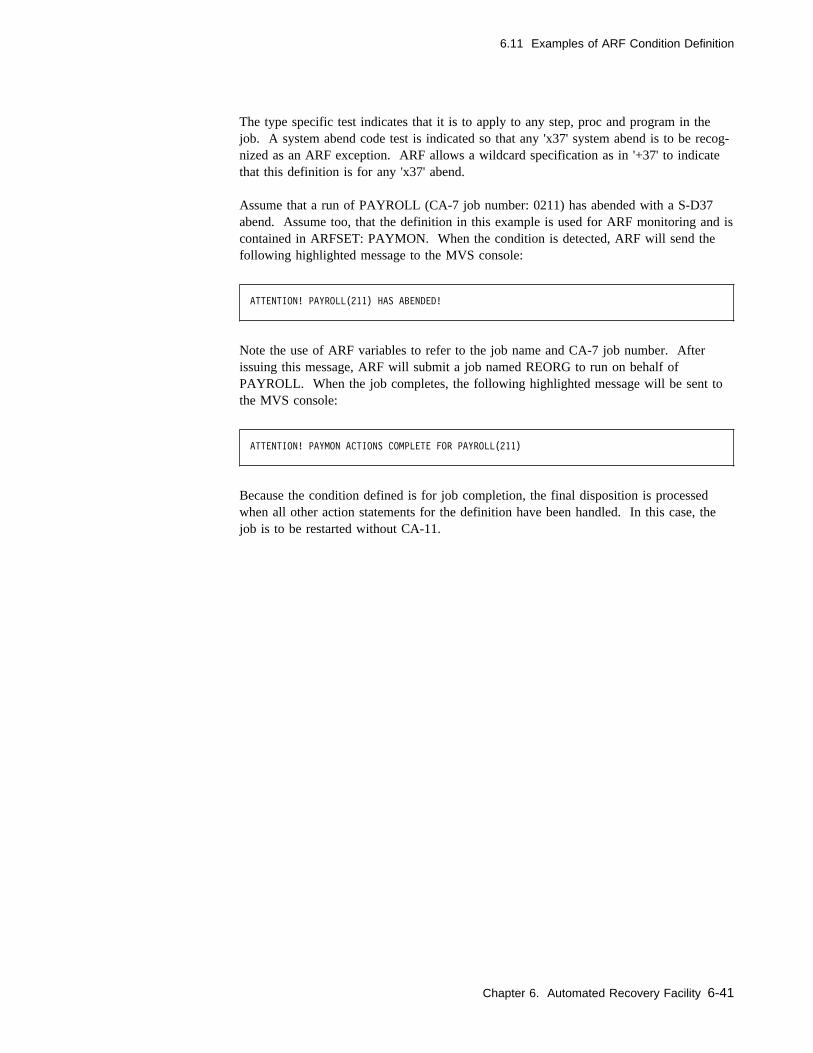
6.11 Examples of ARF Condition Definition
The type specific test indicates that it is to apply to any step, proc and program in thejob. A system abend code test is indicated so that any 'x37' system abend is to be recog-nized as an ARF exception. ARF allows a wildcard specification as in '+37' to indicatethat this definition is for any 'x37' abend.
Assume that a run of PAYROLL (CA-7 job number: 0211) has abended with a S-D37abend. Assume too, that the definition in this example is used for ARF monitoring and iscontained in ARFSET: PAYMON. When the condition is detected, ARF will send thefollowing highlighted message to the MVS console:
ATTENTION! PAYROLL(211) HAS ABENDED!
Note the use of ARF variables to refer to the job name and CA-7 job number. Afterissuing this message, ARF will submit a job named REORG to run on behalf ofPAYROLL. When the job completes, the following highlighted message will be sent tothe MVS console:
ATTENTION! PAYMON ACTIONS COMPLETE FOR PAYROLL(211)
Because the condition defined is for job completion, the final disposition is processedwhen all other action statements for the definition have been handled. In this case, thejob is to be restarted without CA-11.
Chapter 6. Automated Recovery Facility 6-41
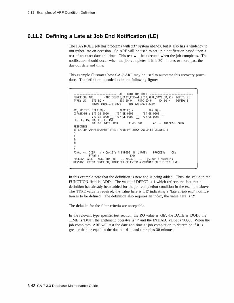
6.11 Examples of ARF Condition Definition
6.11.2 Defining a Late at Job End Notification (LE)
The PAYROLL job has problems with x37 system abends, but it also has a tendency torun rather late on occasion. So ARF will be used to set up a notification based upon atest of an exact date and time. This test will be executed when the job completes. Thenotification should occur when the job completes if it is 30 minutes or more past thedue-out date and time.
This example illustrates how CA-7 ARF may be used to automate this recovery proce-dure. The definition is coded as in the following figure:
� � ---------------------------- ARF CONDITION EDIT ----------------------------
FUNCTION: ADD (ADD,DELETE,EXIT,FORMAT,LIST,REPL,SAVE,SR,SS) DEFCT: �1
TYPE: LE SYS EQ C SID EQ � RSTC EQ � EM EQ C DEFID: 2
FROM: �1�11975 ���1 TO: 12312�74 2359
JC, SC TST: STEP EQ C PROC EQ C PGM EQ C
CC/ABENDS : ??? GE ���� __ ??? GE ���� __ ??? GE ���� __
??? GE ���� __ ??? GE ���� __ ??? GE ����
EC, EE, IS, LB, LE, LS TST:
RO: GE DATE: DOD TIME: DOT AO: + INT/ADJ: ��3�
RESPONSES:
1: AM,CM=T,U=FRED,M=HEY FRED! YOUR PAYCHECK COULD BE DELAYED!!
2:
3:
4:
5:
6:
7:
FINAL -- DISP : N CA-11?: N BYPGDG: N USAGE: PROCESS: CC:
START : END :
PROGRAM: AR32 MSG-INDX: �� -- AR.3.1 -- yy.ddd / hh:mm:ss
MESSAGE: ENTER FUNCTION, TRANSFER OR ENTER A COMMAND ON THE TOP LINE
( )
In this example note that the definition is new and is being added. Thus, the value in theFUNCTION field is 'ADD'. The value of DEFCT is 1 which reflects the fact that adefinition has already been added for the job completion condition in the example above.The TYPE value is required, the value here is 'LE' indicating a "late at job end" notifica-tion is to be defined. The definition also requires an index, the value here is '2'.
The defaults for the filter criteria are acceptable.
In the relevant type specific test section, the RO value is 'GE', the DATE is 'DOD', theTIME is 'DOT', the arithmetic operator is '+' and the INT/ADJ value is '0030'. When thejob completes, ARF will test the date and time at job completion to determine if it isgreater than or equal to the due-out date and time plus 30 minutes.
6-42 CA-7 3.3 Database Maintenance Guide

6.11 Examples of ARF Condition Definition
When the ARF condition is detected, the following message will be sent to the TSO userwhose ID is 'FRED':
HEY FRED! YOUR PAYCHECK COULD BE DELAYED!!!
There are no other actions following this one. This is not a job completion event so therewill be no final disposition processing. ARF recovery is complete for this exception.
Chapter 6. Automated Recovery Facility 6-43

6-44 CA-7 3.3 Database Maintenance Guide
Chapter 7. Workload Documentation
CA-7 permits the entry of free-form user documentation (prose) of the workload at virtu-ally any level. This may range from a general description to specific instructions on howa particular function at a specified workstation is to be performed. Some of the doc-umentation features are:
� Ready access to documentation through CA-7 terminals.
� Realtime, online updating from a change control or production control area.
� Segmenting documentation into user-defined categories (that is, restart information,user abends, control card layouts, balancing instructions, setup requirements, and soforth).
� Adding documentation (prose) through any authorized CA-7 terminal using the DB.4screens and edit facility of database maintenance.
Once defined, you may define documentation:
� With the LPROS command.
� With the DB.4 screens (on which the documentation is also defined and maintained).
� As a list option in several other inquiry commands such as LQ, LPRE, LJOB, and soforth.
� Automatically in some cases. (See 7.2, “Special Documentation Features” onpage 7-26.)
Chapter 7. Workload Documentation 7-1

7.1 Workload Documentation Screens
7.1 Workload Documentation Screens
There are six predefined major categories of documentation, each with its own uniquedefinition screen. Within the documentation defined through these screens, the user mayembed special user-defined segments as discussed in 7.2, “Special DocumentationFeatures” on page 7-26. You may select the appropriate screen from the DB.4 Menudisplay. Separate screens are provided for:
� Job documentation � System documentation � Network documentation � User-designated documentation� Data set documentation
� DD documentation
If user documentation already exists, a user program could be coded to produce BatchTerminal Interface PROSE commands. These commands with the documentation couldbe the input to the Batch Terminal Interface program and the documentation could beadded to the CA-7 database.
Also, if the documentation exists as members of a PDS that is available to CA-7, it couldbe fetched and edited using the DB.7 screen and saved in the Active Area. The usercould then enter the top line DB.4 command, select the appropriate category, perform theEDIT function, and then SAVE the documentation to the database. Both of thesemethods could save the user from having to retype a long documentation description.
7-2 CA-7 3.3 Database Maintenance Guide

7.1 Workload Documentation Screens
7.1.1 DB.4 Menu Screen
Use this screen for selecting various documentation functions.
� �
--------------------- CA-7 WORKLOAD DOCUMENTATION MENU ---------------------
FUNCTION ===> xxxxxxxx
DOCUMENTATION FOR:
1 - CPU JOB
2 - INPUT/OUTPUT NETWORK
3 - USER-DEFINED ITEM
4 - DATA SET
5 - DD STATEMENT
6 - APPLICATION SYSTEM
PROGRAM: SM1� MSG-INDX: nn -- DB.4 -- yy.ddd / hh:mm:ss
MESSAGE:
( )
To display, enter:
� 4 as the FUNCTION on the DB Menu screen.� DB.4 as the FUNCTION on any other menu or formatted input screen.� DB.4 or PROSE as a top line command.
To exit:
� Press the PF3 key to return to the DB Menu screen except with the TSO/ISPF inter-face when PF3 has been assigned to some other function.
� Move the cursor to the top line of the screen and enter the desired top line commandif yet another function is desired.
7.1.1.1 Usage Notes
The desired documentation type is selected by entering the appropriate FUNCTION valueand pressing the Enter key.
Chapter 7. Workload Documentation 7-3
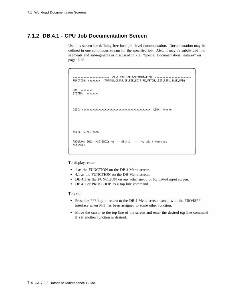
7.1 Workload Documentation Screens
7.1.2 DB.4.1 - CPU Job Documentation Screen
Use this screen for defining free-form job level documentation. Documentation may bedefined in one continuous stream for the specified job. Also, it may be subdivided intosegments and subsegments as discussed in 7.2, “Special Documentation Features” onpage 7-26.
� �
------------------------ CA-7 CPU JOB DOCUMENTATION ------------------------
FUNCTION: xxxxxxxx (APPEND,CLEAR,DELETE,EDIT,FE,FETCH,LIST,REPL,SAVE,UPD)
JOB: xxxxxxxx
SYSTEM: xxxxxxxx
DESC: xxxxxxxxxxxxxxxxxxxxxxxxxxxxxxxxxxxxxxxxxxxxx LINK: nnnnnn
ACTIVE SIZE: nnnn
PROGRAM: SM11 MSG-INDX: nn -- DB.4.1 -- yy.ddd / hh:mm:ss
MESSAGE:
( )
To display, enter:
� 1 as the FUNCTION on the DB.4 Menu screen.� 4.1 as the FUNCTION on the DB Menu screen.� DB.4.1 as the FUNCTION on any other menu or formatted input screen.� DB.4.1 or PROSE,JOB as a top line command.
To exit:
� Press the PF3 key to return to the DB.4 Menu screen except with the TSO/ISPFinterface when PF3 has been assigned to some other function.
� Move the cursor to the top line of the screen and enter the desired top line commandif yet another function is desired.
7-4 CA-7 3.3 Database Maintenance Guide
7.1 Workload Documentation Screens
7.1.2.1 Field Descriptions
FUNCTION: The function to be performed. Value must be the name of some otherscreen or one of the following:
APPEND Retrieves documentation data from the database andattaches documentation text to the end of any existinglines in the Active Area (text work area).
CLEAR Clears screen input data fields and clears the user's ActiveArea.
DELETE Deletes a documentation member from the database.
EDIT Transfers the user to the edit facility and allows text proc-essing. See Chapter 11, “Edit Facility” on page 11-1 andfollowing subtopics for a discussion of the available com-mands for processing the desired text.
FE Combination FETCH and EDIT.
FETCH Retrieves documentation data from the database andreplaces the user's Active Area with documentation text.
LIST Lists documentation data only. In batch, a formattedscreen is not listed; only a found or not found message isreturned.
REPL Replaces a documentation member in the database.
SAVE Adds a new documentation member to the database.
UPD Updates DESC and LINK fields only. It does not affectthe documentation text.
Required: YesBatch keyword: Positional parameter
n/a This field has a constant value of JOB for job documentation.
Required: Yes for batch onlyBatch keyword: Positional parameter
JOB: The job name for which the indicated function is to be performed.
Size/Type: 1 to 8 alphanumeric charactersRequired: YesBatch keyword: JOB
SYSTEM: Identifies the system name or system ID related to the job for the doc-umentation being defined.
Size/Type: 1 to 8 alphanumeric charactersRequired: NoBatch keyword: SYSTEM
Chapter 7. Workload Documentation 7-5
7.1 Workload Documentation Screens
DESC: An optional description of the job.
Size/Type: 1 to 45 alphanumeric charactersRequired: NoBatch keyword: DESC
LINK: The number of another documentation member to link to the doc-umentation member listed. Linking documentation members togethercauses them to be listed together as if they were a single member.The LINK member is listed after the requested member when usingthe LPROS command only.
Size/Type: 1 to 6 numeric charactersRequired: NoBatch keyword: LINK
Note: It is possible to create an LPROS loop. Linked documentationshould not be linked to itself. The following example shows aloop:
A linked to B
B linked to C
C linked to A
ACTIVE SIZE: A system-generated field which tells how many lines of text exist inthe Active Area for the current terminal session.
7-6 CA-7 3.3 Database Maintenance Guide

7.1 Workload Documentation Screens
7.1.3 DB.4.2 - Input/Output Network Documentation Screen
Use this screen for defining network level documentation. It should not be used if theSCHD-PROSE field on the DB.5 screen was used for the network. Documentation maybe defined in one continuous stream for the specified network. Also, it may be subdi-vided into segments and subsegments as discussed in 7.2, “Special DocumentationFeatures” on page 7-26.
� �
----------------- CA-7 INPUT/OUTPUT NETWORK DOCUMENTATION ------------------
FUNCTION: xxxxxxxx (APPEND,CLEAR,DELETE,EDIT,FE,FETCH,LIST,REPL,SAVE,UPD)
JOB: xxxxxxxx
SYSTEM: xxxxxxxx
NETWORK: xxxxxxxx
DESC: xxxxxxxxxxxxxxxxxxxxxxxxxxxxxxxxxxxxxxxxxxxxx LINK: nnnnnn
STEP: xxxxxxxx DDNAME: xxxxxxxx
REPORT-ID: xxxxxxxxxxxxxxxxxxxx
FORM: xxxxxxxx TRAIN: xx CARRIAGE: xxxx COPIES: nnn
ACTIVE SIZE: nnnn
PROGRAM: SM11 MSG-INDX: nn -- DB.4.2 -- yy.ddd / hh:mm:ss
MESSAGE:
( )
To display, enter:
� 2 as the FUNCTION on the DB.4 Menu screen.� 4.2 as the FUNCTION on the DB Menu screen.� DB.4.2 as the FUNCTION on any other menu or formatted input screen.� DB.4.2 or PROSE,NWK as a top line command.
To exit:
� Press the PF3 key to return to the DB.4 Menu screen except with the TSO/ISPFinterface when PF3 has been assigned to some other function.
� Move the cursor to the top line of the screen and enter the desired top line commandif yet another function is desired.
Chapter 7. Workload Documentation 7-7

7.1 Workload Documentation Screens
7.1.3.1 Field Descriptions
FUNCTION: The function to be performed. Value must be the name of some otherscreen or one of following:
APPEND Retrieves documentation data from the database andattaches documentation text to the end of any existinglines in the Active Area (text work area).
CLEAR Clears screen input data fields and clears the user's ActiveArea.
DELETE Deletes a documentation member from the database.
EDIT Transfers the user to the edit facility and allows text proc-essing. See Chapter 11, “Edit Facility” on page 11-1 andfollowing subtopics for a discussion of the available com-mands for processing the desired text.
FE Combination FETCH and EDIT.
FETCH Retrieves documentation data from the database andreplaces the user's Active Area with documentation text.
LIST Lists documentation data only. In batch, a formattedscreen is not listed; only a found or not found message isreturned.
REPL Replaces a documentation member in the database.
SAVE Adds a new documentation member to the database.
UPD Updates formatted screen fields only. It does not affectthe documentation text.
Required: YesBatch keyword: Positional parameter
n/a This field has a constant value of NWK for network documentation.
Required: Yes for batch onlyBatch keyword: Positional parameter
JOB: Indicates the job related to the network for the documentation beingdefined.
Size/Type: 1 to 8 alphanumeric charactersRequired: NoBatch keyword: JOB
SYSTEM: Identifies the system name or system ID related to the network for thedocumentation being defined.
Size/Type: 1 to 8 alphanumeric charactersRequired: NoBatch keyword: SYSTEM
7-8 CA-7 3.3 Database Maintenance Guide
7.1 Workload Documentation Screens
NETWORK: The network for which the documentation is being defined.
Size/Type: 1 to 8 alphanumeric charactersRequired: YesBatch keyword: NETWORK
DESC: A description of the network.
Size/Type: 1 to 45 alphanumeric charactersRequired: NoBatch keyword: DESC
LINK: The number of another documentation member to link to the doc-umentation member listed. Linking documentation members togethercauses them to be listed together as if they were a single member.The LINK member is listed after the requested member when usingthe LPROS command only.
Size/Type: 1 to 6 numeric charactersRequired: NoBatch keyword: LINK
Note: It is possible to create an LPROS loop. Linked documentationshould not be linked to itself. The following example shows aloop:
A linked to B
B linked to C
C linked to A
The following fields are informational only:
STEP: The name of a job step in a particular job for which the network doc-umentation is being defined.
Size/Type: 1 to 8 alphanumeric charactersRequired: NoBatch keyword: STEP
DDNAME: A ddname for which the documentation is being defined.
Size/Type: 1 to 8 alphanumeric charactersRequired: NoBatch keyword: DD
REPORT-ID: Identification of a printed report.
Size/Type: 1 to 20 alphanumeric charactersRequired: NoBatch keyword: REPORT
FORM: Output form number.
Size/Type: 1 to 8 alphanumeric charactersRequired: NoBatch keyword: FORM
Chapter 7. Workload Documentation 7-9

7.1 Workload Documentation Screens
TRAIN: Type of printer train required.
Size/Type: 1 to 2 alphanumeric charactersRequired: NoBatch keyword: TRAIN
CARRIAGE: Type of carriage control required.
Size/Type: 1 to 4 alphanumeric charactersRequired: NoBatch keyword: CARR
COPIES: Number of original copies required.
Size/Type: 1 to 3 numeric characters from 0 to 255Required: NoBatch keyword: COPIES
ACTIVE SIZE: A system-generated field which shows the number of lines of textexisting in the Active Area for the current terminal session.
7-10 CA-7 3.3 Database Maintenance Guide
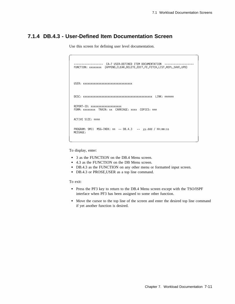
7.1 Workload Documentation Screens
7.1.4 DB.4.3 - User-Defined Item Documentation Screen
Use this screen for defining user level documentation.
� �
------------------- CA-7 USER-DEFINED ITEM DOCUMENTATION -------------------
FUNCTION: xxxxxxxx (APPEND,CLEAR,DELETE,EDIT,FE,FETCH,LIST,REPL,SAVE,UPD)
USER: xxxxxxxxxxxxxxxxxxxxxxxxxxxxxxxx
DESC: xxxxxxxxxxxxxxxxxxxxxxxxxxxxxxxxxxxxxxxxxxxxx LINK: nnnnnn
REPORT-ID: xxxxxxxxxxxxxxxxxxxx
FORM: xxxxxxxx TRAIN: xx CARRIAGE: xxxx COPIES: nnn
ACTIVE SIZE: nnnn
PROGRAM: SM11 MSG-INDX: nn -- DB.4.3 -- yy.ddd / hh:mm:ss
MESSAGE:
( )
To display, enter:
� 3 as the FUNCTION on the DB.4 Menu screen.� 4.3 as the FUNCTION on the DB Menu screen.� DB.4.3 as the FUNCTION on any other menu or formatted input screen.� DB.4.3 or PROSE,USER as a top line command.
To exit:
� Press the PF3 key to return to the DB.4 Menu screen except with the TSO/ISPFinterface when PF3 has been assigned to some other function.
� Move the cursor to the top line of the screen and enter the desired top line commandif yet another function is desired.
Chapter 7. Workload Documentation 7-11
7.1 Workload Documentation Screens
7.1.4.1 Field Descriptions
FUNCTION: The function to be performed. Value must be the name of some otherscreen or one of the following:
APPEND Retrieves documentation data from the data base andattaches documentation text to the end of any existinglines in the Active Area (text work area).
CLEAR Clears screen input data fields and clears the user's ActiveArea.
DELETE Deletes a documentation member from the database.
EDIT Transfers the user to the EDIT facility and allows textprocessing. See Chapter 11, “Edit Facility” on page 11-1and following subtopics for a discussion of the availablecommands for processing the desired text.
FE Combination FETCH and EDIT.
FETCH Retrieves documentation data from the database andreplaces the user's Active Area with documentation text.
LIST Lists documentation data only. In batch, a formattedscreen is not listed; only a found or not found message isreturned.
REPL Replaces a documentation member in the database.
SAVE Adds a new documentation member to the database.
UPD Updates formatted screen fields only. It does not affectthe documentation text.
Required: YesBatch keyword: Positional parameter
n/a This field has a constant value of USER for user documentation.
Required: Yes for batch onlyBatch keyword: Positional parameter
7-12 CA-7 3.3 Database Maintenance Guide
7.1 Workload Documentation Screens
USER: A required name used to supply a unique identifier for the informationbeing defined by the user documentation entry. This field must followOS data set naming conventions and must not correspond to anysystem name, job name, data set name, job-step-ddname combination,or workstation name which exists (or will exist) in the CA-7 system.
Size/Type: 1 to 32 alphanumeric charactersRequired: YesBatch keyword: USER
DESC: An optional description of the user entry.
Size/Type: 1 to 45 alphanumeric charactersRequired: NoBatch keyword: DESC
LINK: The number of another documentation member to link to the doc-umentation member listed. Linking documentation members togethercauses them to be listed together as if they were a single member.The LINK member is listed after the requested member when usingthe LPROS command only.
Size/Type: 1 to 6 numeric charactersRequired: NoBatch keyword: LINK
Note: It is possible to create an LPROS loop. Linked documentationshould not be linked to itself. The following example shows aloop:
A linked to B
B linked to C
C linked to A
The following fields are informational only:
REPORT-ID: Identification of a printed report.
Size/Type: 1 to 20 alphanumeric charactersRequired: NoBatch keyword: REPORT
FORM: Output form number.
Size/Type: 1 to 8 alphanumeric charactersRequired: NoBatch keyword: FORM
TRAIN: Type of printer train required.
Size/Type: 1 to 2 alphanumeric charactersRequired: NoBatch keyword: TRAIN
Chapter 7. Workload Documentation 7-13

7.1 Workload Documentation Screens
CARRIAGE: Type of carriage control required.
Size/Type: 1 to 4 alphanumeric charactersRequired: NoBatch keyword: CARR
COPIES: Number of original copies required.
Size/Type: 1 to 3 numeric characters from 0 to 255Required: NoBatch keyword: COPIES
ACTIVE SIZE: A system-generated field which shows the number of lines of textexisting in the Active Area for the current terminal session.
7-14 CA-7 3.3 Database Maintenance Guide

7.1 Workload Documentation Screens
7.1.5 DB.4.4 - Data Set Documentation Screen
Use this screen for defining data set level documentation. Data sets whose name islonger than 41 characters cannot use this screen.
� �
----------------------- CA-7 DATA SET DOCUMENTATION ------------------------
FUNCTION: xxxxxxxx (APPEND,CLEAR,DELETE,EDIT,FE,FETCH,LIST,REPL,SAVE,UPD)
DSN: xxxxxxxxxxxxxxxxxxxxxxxxxxxxxxxxxxxxxxxxx DSNBR: nnnnnn
DESC: xxxxxxxxxxxxxxxxxxxxxxxxxxxxxxxxxxxxxxxxxxxxx LINK: nnnnnn
STEP: xxxxxxxx DDNAME: xxxxxxxx
REPORT-ID: xxxxxxxxxxxxxxxxxxxx
FORM: xxxxxxxx TRAIN: xx CARRIAGE: xxxx COPIES: nnn
ACTIVE SIZE: nnnn
PROGRAM: SM11 MSG-INDX: nn -- DB.4.4 -- yy.ddd / hh:mm:ss
MESSAGE:
( )
To display, enter:
� 4 as the FUNCTION on the DB.4 Menu screen.� 4.4 as the FUNCTION on the DB Menu screen.� DB.4.4 as the FUNCTION on any other menu or formatted input screen.� DB.4.4 or PROSE,DSN as a top line command.
To exit:
� Press the PF3 key to return to the DB.4 Menu screen except with the TSO/ISPFinterface when PF3 has been assigned to some other function.
� Move the cursor to the top line of the screen and enter the desired top line commandif yet another function is desired.
Chapter 7. Workload Documentation 7-15

7.1 Workload Documentation Screens
7.1.5.1 Field Descriptions
FUNCTION: The function to be performed. Value must be the name of some otherscreen or one of the following:
APPEND Retrieves documentation data from the database andattaches documentation text to the end of any existinglines in the Active Area (text work area).
CLEAR Clears screen input data fields and clears the user's ActiveArea.
DELETE Deletes a documentation member from the database.
EDIT Transfers the user to the EDIT facility and allows textprocessing. See Chapter 11, “Edit Facility” on page 11-1and following subtopics for a discussion of the availablecommands for processing the desired text.
FE Combination FETCH and EDIT.
FETCH Retrieves documentation data from the database andreplaces the user's Active Area with documentation text.
LIST Lists documentation data only. In batch, a formattedscreen is not listed; only a found or not found message isreturned.
REPL Replaces a documentation member in the database.
SAVE Adds a new documentation member to the database.
UPD Updates formatted screen fields only. It does not affectthe documentation text.
Required: YesBatch keyword: Positional parameter
n/a This field has a constant value of DSN for data set documentation.
Required: Yes for batch onlyBatch keyword: Positional parameter
DSN: The data set name for which the documentation is being defined.
Size/Type: 1 to 41 alphanumeric charactersRequired: Yes (unless DSNBR is used)Batch keyword: DSN
Note: The data set name must not exceed 41 characters to allow PP.to be added as part of the data set name in the IDs.
7-16 CA-7 3.3 Database Maintenance Guide
7.1 Workload Documentation Screens
DSNBR: Identifies the data set for which the documentation is being supplied.Must be the data set number assigned by CA-7 when the data set wasfirst defined.
Size/Type: 1 to 6 numeric charactersRequired: Yes (unless DSN is used)Batch keyword: DSNBR
DESC: An optional description of the data set.
Size/Type: 1 to 45 alphanumeric charactersRequired: NoBatch keyword: DESC
LINK: The number of another documentation member to link to the doc-umentation member listed. Linking documentation members togethercauses them to be listed together as if they were a single member.The LINK member is listed after the requested member when usingthe LPROS command only.
Size/Type: 1 to 6 numeric charactersRequired: NoBatch keyword: LINK
Note: It is possible to create an LPROS loop. Linked documentationshould not be linked to itself. The following example shows aloop:
A linked to B
B linked to C
C linked to A
The following fields are informational only:
REPORT-ID: Identification of a printed report.
Size/Type: 1 to 20 alphanumeric charactersRequired: NoBatch keyword: REPORT
FORM: Output form number.
Size/Type: 1 to 8 alphanumeric charactersRequired: NoBatch keyword: FORM
TRAIN: Type of printer train required.
Size/Type: 1 to 2 alphanumeric charactersRequired: NoBatch keyword: TRAIN
Chapter 7. Workload Documentation 7-17

7.1 Workload Documentation Screens
CARRIAGE: Type of carriage control required.
Size/Type: 1 to 4 alphanumeric charactersRequired: NoBatch keyword: CARR
COPIES: Number of original copies required.
Size/Type: 1 to 3 numeric characters from 0 to 255Required: NoBatch keyword: COPIES
ACTIVE SIZE: A system-generated field which shows the number of lines of textexisting in the Active Area for the current terminal session.
7-18 CA-7 3.3 Database Maintenance Guide
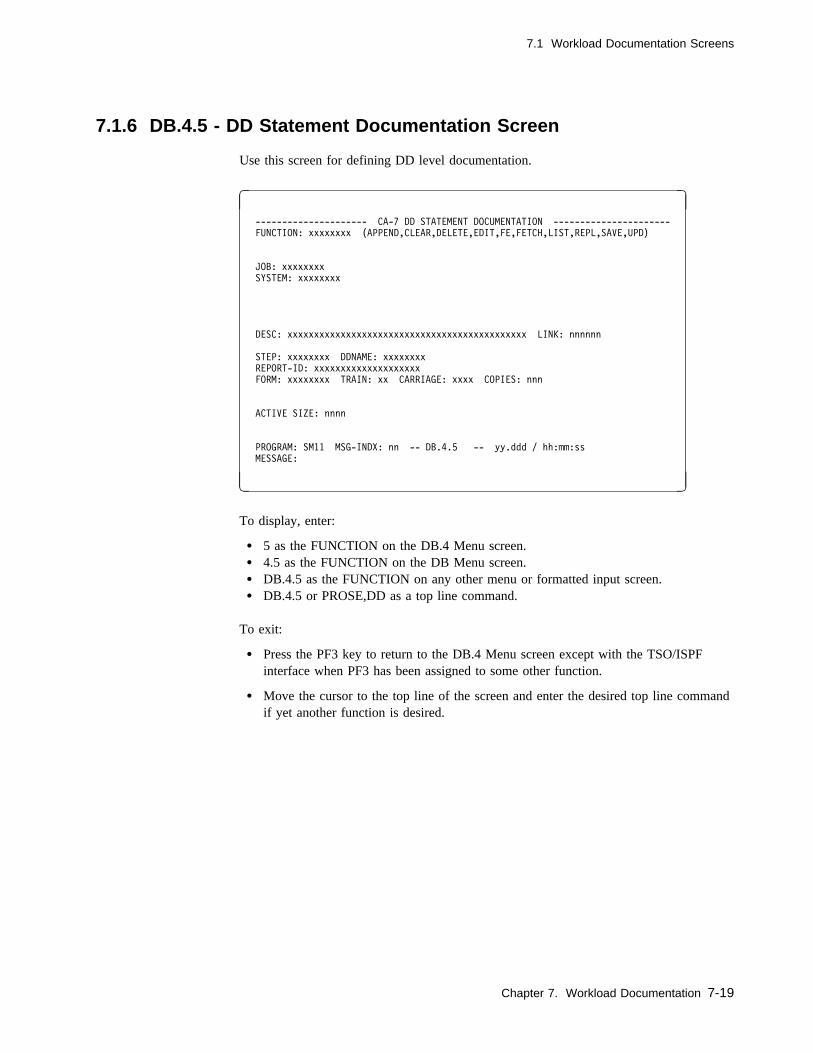
7.1 Workload Documentation Screens
7.1.6 DB.4.5 - DD Statement Documentation Screen
Use this screen for defining DD level documentation.
� �
--------------------- CA-7 DD STATEMENT DOCUMENTATION ----------------------
FUNCTION: xxxxxxxx (APPEND,CLEAR,DELETE,EDIT,FE,FETCH,LIST,REPL,SAVE,UPD)
JOB: xxxxxxxx
SYSTEM: xxxxxxxx
DESC: xxxxxxxxxxxxxxxxxxxxxxxxxxxxxxxxxxxxxxxxxxxxx LINK: nnnnnn
STEP: xxxxxxxx DDNAME: xxxxxxxx
REPORT-ID: xxxxxxxxxxxxxxxxxxxx
FORM: xxxxxxxx TRAIN: xx CARRIAGE: xxxx COPIES: nnn
ACTIVE SIZE: nnnn
PROGRAM: SM11 MSG-INDX: nn -- DB.4.5 -- yy.ddd / hh:mm:ss
MESSAGE:
( )
To display, enter:
� 5 as the FUNCTION on the DB.4 Menu screen.� 4.5 as the FUNCTION on the DB Menu screen.� DB.4.5 as the FUNCTION on any other menu or formatted input screen.� DB.4.5 or PROSE,DD as a top line command.
To exit:
� Press the PF3 key to return to the DB.4 Menu screen except with the TSO/ISPFinterface when PF3 has been assigned to some other function.
� Move the cursor to the top line of the screen and enter the desired top line commandif yet another function is desired.
Chapter 7. Workload Documentation 7-19

7.1 Workload Documentation Screens
7.1.6.1 Field Descriptions
FUNCTION: The function to be performed. Value must be the name of some otherscreen or one of the following:
APPEND Retrieves documentation data from the database andattaches documentation text to the end of any existinglines in the Active Area (text work area).
CLEAR Clears screen input data fields and clears the user's ActiveArea.
DELETE Deletes a documentation member from the database.
EDIT Transfers the user to the EDIT facility and allows textprocessing. See Chapter 11, “Edit Facility” on page 11-1and following subtopics for a discussion of the availablecommands for processing the desired text.
FE Combination FETCH and EDIT.
FETCH Retrieves documentation data from the database andreplaces the user's Active Area with documentation text.
LIST Lists documentation data only. In batch, a formattedscreen is not listed; only a found or not found message isreturned.
REPL Replaces a documentation member in the database.
SAVE Adds a new documentation member to the database.
UPD Updates formatted screen fields only. It does not affectthe documentation text.
Required: YesBatch keyword: Positional parameter
n/a This field has a constant value of DD for the DD documentation.
Required: Yes for batch onlyBatch keyword: Positional parameter
JOB: Indicates the job containing the ddname for the documentation beingdefined.
Size/Type: 1 to 8 alphanumeric charactersRequired: YesBatch keyword: JOB
7-20 CA-7 3.3 Database Maintenance Guide

7.1 Workload Documentation Screens
DESC: Description of the data set.
Size/Type: 1 to 45 alphanumeric charactersRequired: NoBatch keyword: DESC
LINK: The number of another documentation member to link to the doc-umentation member listed. Linking documentation members togethercauses them to be listed together as if they were a single member.The LINK member is listed after the requested member when usingthe LPROS command only.
Size/Type: 1 to 6 numeric charactersRequired: NoBatch keyword: LINK
Note: It is possible to create an LPROS loop. Linked documentationshould not be linked to itself. The following example shows aloop:
A linked to B
B linked to C
C linked to A
STEP: This field indicates the step of the JOB for the DD documentationbeing defined.
Size/Type: 1 to 8 alphanumeric charactersRequired: YesBatch keyword: STEP
DDNAME: This field indicates the ddname for which the documentation is beingdefined.
Size/Type: 1 to 8 alphanumeric charactersRequired: YesBatch keyword: DD
The following fields are informational only:
REPORT-ID: Identification of a printed report.
Size/Type: 1 to 20 alphanumeric charactersRequired: NoBatch keyword: REPORT
FORM: Output form number.
Size/Type: 1 to 8 alphanumeric charactersRequired: NoBatch keyword: FORM
Chapter 7. Workload Documentation 7-21

7.1 Workload Documentation Screens
TRAIN: Type of printer train required.
Size/Type: 1 to 2 alphanumeric charactersRequired: NoBatch keyword: TRAIN
CARRIAGE: Type of carriage control required.
Size/Type: 1 to 4 alphanumeric charactersRequired: NoBatch keyword: CARR
COPIES: Number of original copies required.
Size/Type: 1 to 3 numeric characters from 0 to 255Required: NoBatch keyword: COPIES
ACTIVE SIZE: A system-generated field which shows the number of lines of textexisting in the Active Area for the current terminal session.
7-22 CA-7 3.3 Database Maintenance Guide

7.1 Workload Documentation Screens
7.1.7 DB.4.6 - Application System Documentation Screen
Use this screen for defining system level documentation.
� �
------------------ CA-7 APPLICATION SYSTEM DOCUMENTATION -------------------
FUNCTION: xxxxxxxx (APPEND,CLEAR,DELETE,EDIT,FE,FETCH,LIST,REPL,SAVE,UPD)
SYSTEM: xxxxxxxx
DESC: xxxxxxxxxxxxxxxxxxxxxxxxxxxxxxxxxxxxxxxxxxxxx LINK: nnnnnn
ACTIVE SIZE: nnnn
PROGRAM: SM11 MSG-INDX: nn -- DB.4.6 -- yy.ddd / hh:mm:ss
MESSAGE:
( )
To display, enter:
� 6 as the FUNCTION on the DB.4 Menu screen.� 4.6 as the FUNCTION on the DB Menu screen.� DB.4.6 as the FUNCTION on any other menu or formatted input screen.� DB.4.6 or PROSE,SYS as a top line command.
To exit:
� Press the PF3 key to return to the DB.4 Menu screen except with the TSO/ISPFinterface when PF3 has been assigned to some other function.
� Move the cursor to the top line of the screen and enter the desired top line commandif yet another function is desired.
Chapter 7. Workload Documentation 7-23
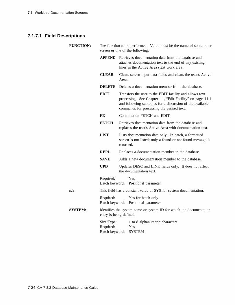
7.1 Workload Documentation Screens
7.1.7.1 Field Descriptions
FUNCTION: The function to be performed. Value must be the name of some otherscreen or one of the following:
APPEND Retrieves documentation data from the database andattaches documentation text to the end of any existinglines in the Active Area (text work area).
CLEAR Clears screen input data fields and clears the user's ActiveArea.
DELETE Deletes a documentation member from the database.
EDIT Transfers the user to the EDIT facility and allows textprocessing. See Chapter 11, “Edit Facility” on page 11-1and following subtopics for a discussion of the availablecommands for processing the desired text.
FE Combination FETCH and EDIT.
FETCH Retrieves documentation data from the database andreplaces the user's Active Area with documentation text.
LIST Lists documentation data only. In batch, a formattedscreen is not listed; only a found or not found message isreturned.
REPL Replaces a documentation member in the database.
SAVE Adds a new documentation member to the database.
UPD Updates DESC and LINK fields only. It does not affectthe documentation text.
Required: YesBatch keyword: Positional parameter
n/a This field has a constant value of SYS for system documentation.
Required: Yes for batch onlyBatch keyword: Positional parameter
SYSTEM: Identifies the system name or system ID for which the documentationentry is being defined.
Size/Type: 1 to 8 alphanumeric charactersRequired: YesBatch keyword: SYSTEM
7-24 CA-7 3.3 Database Maintenance Guide
7.1 Workload Documentation Screens
DESC: An optional description of the system.
Size/Type: 1 to 45 alphanumeric charactersRequired: NoBatch keyword: DESC
LINK: The number of another documentation member to link to the doc-umentation member listed. Linking documentation members togethercauses them to be listed together as if they were a single member.The LINK member is listed after the requested member when usingthe LPROS command only.
Size/Type: 1 to 6 numeric charactersRequired: NoBatch keyword: LINK
Note: It is possible to create an LPROS loop. Linked documentationshould not be linked to itself. The following example shows aloop:
A linked to B
B linked to C
C linked to A
ACTIVE SIZE: A system-generated field which shows how many lines of text exist inthe Active Area for the current terminal session.
Chapter 7. Workload Documentation 7-25
7.2 Special Documentation Features
7.2 Special Documentation Features
There are six major categories of user-defined documentation. Each category has its ownDB.4 screen with which the documentation may be entered and maintained in the data-base. All categories are optional and are provided for user convenience. Each documen-tation member falls within one of six categories:
� Job name � System name � Network name � User level� Data set name
� DD statement
7.2.1 User-Defined Documentation Segments
Within each of the major documentation member types, the user can subdivide documen-tation text into segments. Segments are convenient because they can be accessed individ-ually by name, presenting documentation only on a specific item or set of items.
The user names and defines segments by the use of special pound sign (#) control state-ments. The # control statements begin and end each segment, forming a bookend nota-tion.
7.2.1.1 Reserved Segment Names
The system reserves some names for special use. You should not use segment nameswhich would conflict with the following:
#END #QDESC #RESTART #station-name
Discussions of these special purpose names follow later in this chapter.
7.2.1.2 Rules and Guidelines for Documentation Segmentation
The following rules and guidelines help you make more efficient use of the segmentationtool:
� Adopt a naming convention for segments. This adds ease of retrieval. See 7.2.1.11,“Documenting Naming Conventions” on page 7-32.
� A documentation member can contain one or more segments.
� Each segment must have a name. Segment names must conform to the followingrules:
7-26 CA-7 3.3 Database Maintenance Guide

7.2 Special Documentation Features
– The name is a maximum of 8 characters.
– Commas, as part of the name, are not allowed.
– Alphabetics, numerics, and special characters are allowed.
� A segment name must be unique within the documentation member. A segmentname should be different from the documentation member name of which thesegment is a part.
7.2.1.3 Defining Segment Names
User-defined segments can be an orderly method of documentation. By establishingstandards related to segment names, a powerful tool results. To define a segment name,select an 8-character name meaningful to your environment; precede the name with a #sign. Enter the definition starting in column 1. For example:
#segment-name
The following is a list of potential segment names which could fit into the naming con-ventions for segments:
#DATECARD Format of the date cards used in this job.#progname Description of programs used in the job.#stepname Description of job steps in the job.#DISASTER Instructions for disaster recovery procedures.#RECOVERY Recovery considerations for I/O errors, abends, and so forth.#FILING Instructions for filing input or output.#SETUP I/O media requirements of the job.#CONTACTS Names and numbers of personnel who support the job.#DEVICES I/O device requirements of the job.#CONFLICT Possible processing conflicts with other jobs.#VALIDATE Special manual verification requirements of the job.#AFTERHRS Special procedures occurring after the close of the business day.
Other segment names may be helpful or more meaningful and easy to use in any partic-ular data center. Within the constraints of the few reserved segment names, the user hastotal flexibility in naming documentation segments.
7.2.1.4 Format of Documentation Segments
The format of documentation segments is simple. The first statement must be a#segment-name statement. The #segment-name begins in column 1. Immediately fol-lowing the #segment-name statement is the documentation associated with the name. Thedocumentation is in free-form and control characters are not needed. However, avoidbeginning a documentation line with a #, which the system interprets as a segmentationcontrol character and tries to treat it as a start or an end of a segment or subsegment.
Chapter 7. Workload Documentation 7-27
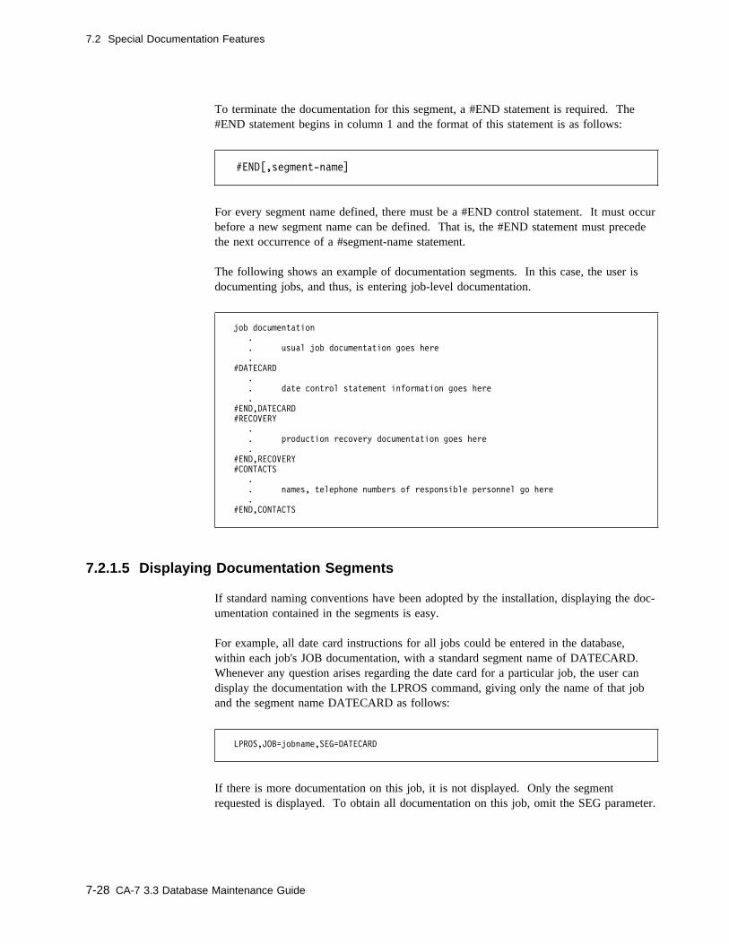
7.2 Special Documentation Features
To terminate the documentation for this segment, a #END statement is required. The#END statement begins in column 1 and the format of this statement is as follows:
#END[,segment-name]
For every segment name defined, there must be a #END control statement. It must occurbefore a new segment name can be defined. That is, the #END statement must precedethe next occurrence of a #segment-name statement.
The following shows an example of documentation segments. In this case, the user isdocumenting jobs, and thus, is entering job-level documentation.
job documentation
.
. usual job documentation goes here
.
#DATECARD
.
. date control statement information goes here
.
#END,DATECARD
#RECOVERY
.
. production recovery documentation goes here
.
#END,RECOVERY
#CONTACTS
.
. names, telephone numbers of responsible personnel go here
.
#END,CONTACTS
7.2.1.5 Displaying Documentation Segments
If standard naming conventions have been adopted by the installation, displaying the doc-umentation contained in the segments is easy.
For example, all date card instructions for all jobs could be entered in the database,within each job's JOB documentation, with a standard segment name of DATECARD.Whenever any question arises regarding the date card for a particular job, the user candisplay the documentation with the LPROS command, giving only the name of that joband the segment name DATECARD as follows:
LPROS,JOB=jobname,SEG=DATECARD
If there is more documentation on this job, it is not displayed. Only the segmentrequested is displayed. To obtain all documentation on this job, omit the SEG parameter.
7-28 CA-7 3.3 Database Maintenance Guide

7.2 Special Documentation Features
By segmenting documentation, the user can view selected parts of the documentation andnot have to view all the documentation at one time.
7.2.1.6 Subsegments
Inside each segment may be subsegments. There are rules and guidelines which apply tosubsegments and they are similar to those for segments.
7.2.1.7 Rules and Guidelines for Subsegments
� Adopt a naming convention for subsegments. Just as naming conventions aid theuser in retrieval of segments, the same holds true with subsegments. See 7.2.1.11,“Documenting Naming Conventions” on page 7-32.
� Each subsegment must have a name. Subsegment names must follow the same rulesas segment names. See 7.2.1.2, “Rules and Guidelines for DocumentationSegmentation” on page 7-26.
� A segment may have one or more subsegments.
� A subsegment name must be different from the segment name of which the subseg-ment is a part.
� A subsegment must end before the end of the segment of which it is a part.
� A subsegment name should not be the same as a reserved segment name. See7.2.1.1, “Reserved Segment Names” on page 7-26.
� A subsegment must be embedded between a #subsegment-name statement and a#END,subsegment-name statement.
7.2.1.8 Defining Subsegment Names
To define a subsegment name, select an 8-character name meaningful in your environ-ment; precede the name with a # sign. Enter the definition starting in column 1. This isexactly the same way segment names are defined:
#subsegment-name
For example, your installation may have two procedures for recovery: one for businesshours and one for nonbusiness hours. To define these two names, you might create twosubsegments within the segment named RECOVERY using the following subsegmentnames:
#DAYTIME
#AFTERHRS
Chapter 7. Workload Documentation 7-29
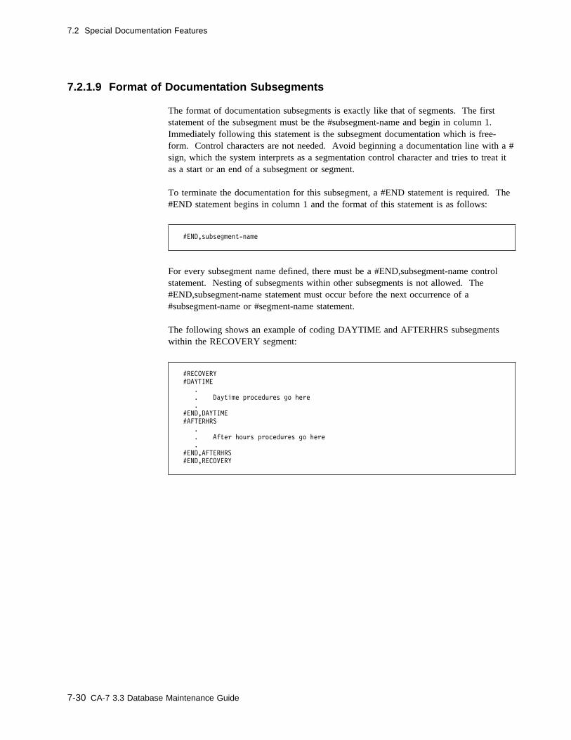
7.2 Special Documentation Features
7.2.1.9 Format of Documentation Subsegments
The format of documentation subsegments is exactly like that of segments. The firststatement of the subsegment must be the #subsegment-name and begin in column 1.Immediately following this statement is the subsegment documentation which is free-form. Control characters are not needed. Avoid beginning a documentation line with a #sign, which the system interprets as a segmentation control character and tries to treat itas a start or an end of a subsegment or segment.
To terminate the documentation for this subsegment, a #END statement is required. The#END statement begins in column 1 and the format of this statement is as follows:
#END,subsegment-name
For every subsegment name defined, there must be a #END,subsegment-name controlstatement. Nesting of subsegments within other subsegments is not allowed. The#END,subsegment-name statement must occur before the next occurrence of a#subsegment-name or #segment-name statement.
The following shows an example of coding DAYTIME and AFTERHRS subsegmentswithin the RECOVERY segment:
#RECOVERY
#DAYTIME
.
. Daytime procedures go here
.
#END,DAYTIME
#AFTERHRS
.
. After hours procedures go here
.
#END,AFTERHRS
#END,RECOVERY
7-30 CA-7 3.3 Database Maintenance Guide

7.2 Special Documentation Features
7.2.1.10 Displaying Documentation Subsegments
If standard naming conventions for subsegments have been adopted by the installation,displaying the documentation contained in the subsegments is easy. The user must knowwhich names are segment names and which names are subsegment names. This is wherestandard naming conventions for both is important.
In the previous example, in the segment named RECOVERY there are two subsegments;one is named DAYTIME and the other AFTERHRS. To display the subsegments, usethe LPROS command. For example:
LPROS,JOB=jobname,SEG=(RECOVERY,AFTERHRS)
This would display only the AFTERHRS subsegment. The SEG parameter requires thatthe segment name appear first, followed by the subsegment name.
To display the other subsegment of the RECOVERY segment, the entry would be asfollows:
LPROS,JOB=jobname,SEG=(RECOVERY,DAYTIME)
The DAYTIME subsegment would display.
To display all subsegments of a segment, only the segment form of LPROS is used. Forexample:
LPROS,JOB=jobname,SEG=RECOVERY
Chapter 7. Workload Documentation 7-31
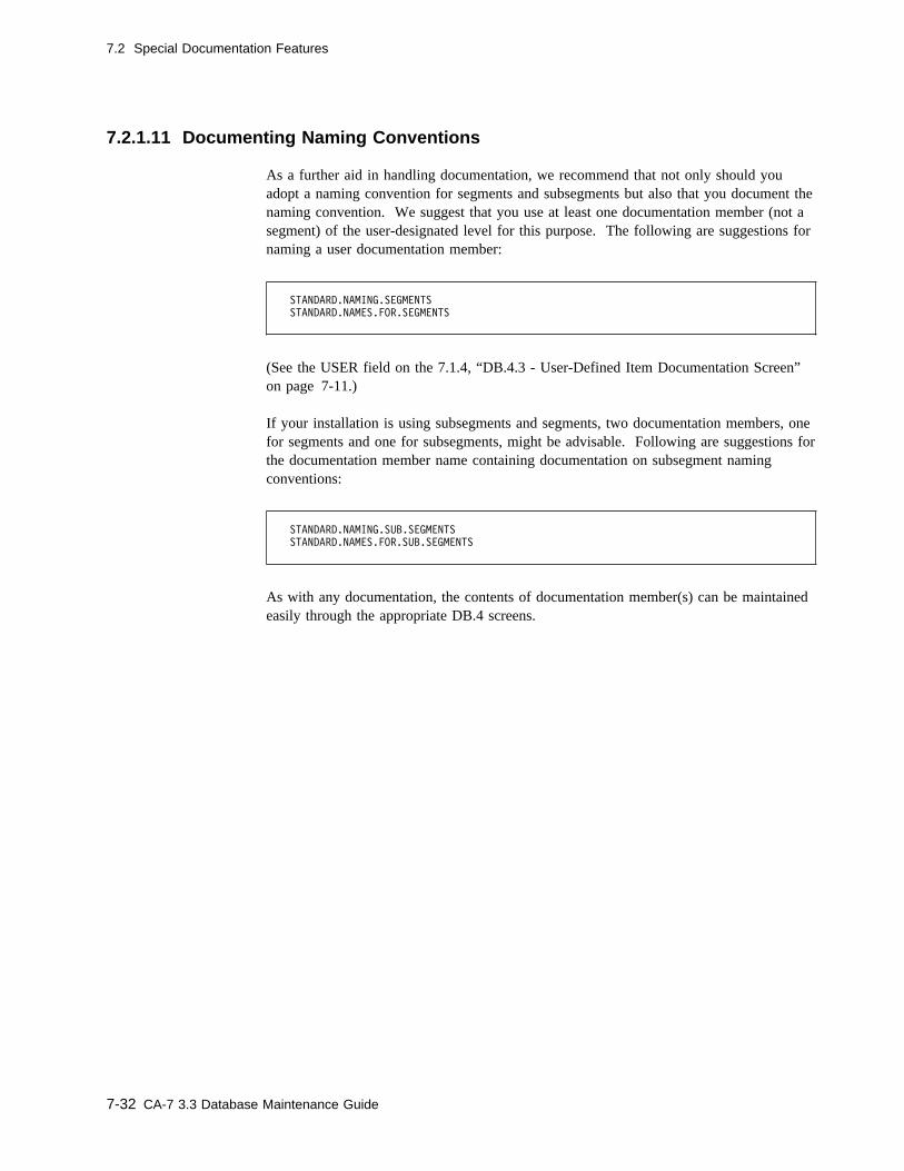
7.2 Special Documentation Features
7.2.1.11 Documenting Naming Conventions
As a further aid in handling documentation, we recommend that not only should youadopt a naming convention for segments and subsegments but also that you document thenaming convention. We suggest that you use at least one documentation member (not asegment) of the user-designated level for this purpose. The following are suggestions fornaming a user documentation member:
STANDARD.NAMING.SEGMENTS
STANDARD.NAMES.FOR.SEGMENTS
(See the USER field on the 7.1.4, “DB.4.3 - User-Defined Item Documentation Screen”on page 7-11.)
If your installation is using subsegments and segments, two documentation members, onefor segments and one for subsegments, might be advisable. Following are suggestions forthe documentation member name containing documentation on subsegment namingconventions:
STANDARD.NAMING.SUB.SEGMENTS
STANDARD.NAMES.FOR.SUB.SEGMENTS
As with any documentation, the contents of documentation member(s) can be maintainedeasily through the appropriate DB.4 screens.
7-32 CA-7 3.3 Database Maintenance Guide
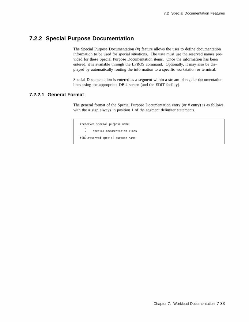
7.2 Special Documentation Features
7.2.2 Special Purpose Documentation
The Special Purpose Documentation (#) feature allows the user to define documentationinformation to be used for special situations. The user must use the reserved names pro-vided for these Special Purpose Documentation items. Once the information has beenentered, it is available through the LPROS command. Optionally, it may also be dis-played by automatically routing the information to a specific workstation or terminal.
Special Documentation is entered as a segment within a stream of regular documentationlines using the appropriate DB.4 screen (and the EDIT facility).
7.2.2.1 General Format
The general format of the Special Purpose Documentation entry (or # entry) is as followswith the # sign always in position 1 of the segment delimiter statements.
#reserved special purpose name
.
. special documentation lines
.
#END,reserved special purpose name
Chapter 7. Workload Documentation 7-33
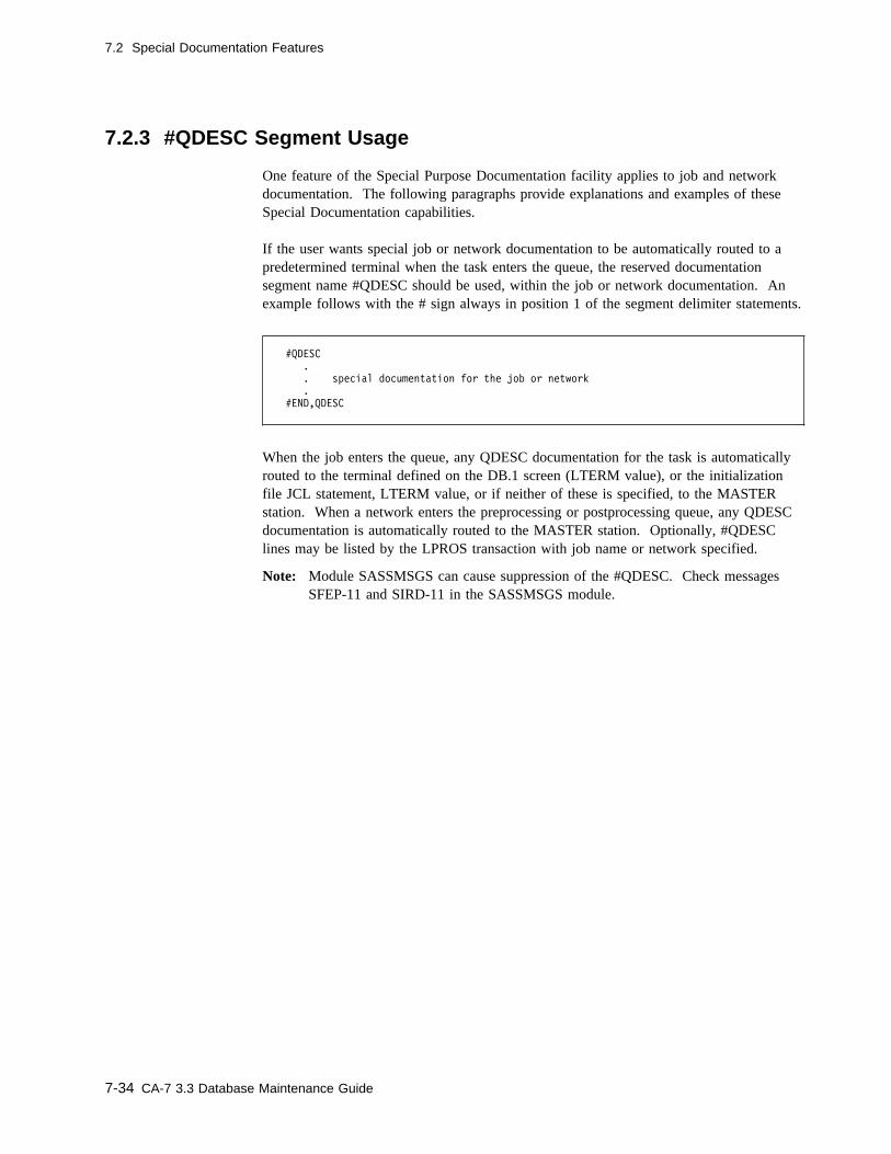
7.2 Special Documentation Features
7.2.3 #QDESC Segment Usage
One feature of the Special Purpose Documentation facility applies to job and networkdocumentation. The following paragraphs provide explanations and examples of theseSpecial Documentation capabilities.
If the user wants special job or network documentation to be automatically routed to apredetermined terminal when the task enters the queue, the reserved documentationsegment name #QDESC should be used, within the job or network documentation. Anexample follows with the # sign always in position 1 of the segment delimiter statements.
#QDESC
.
. special documentation for the job or network
.
#END,QDESC
When the job enters the queue, any QDESC documentation for the task is automaticallyrouted to the terminal defined on the DB.1 screen (LTERM value), or the initializationfile JCL statement, LTERM value, or if neither of these is specified, to the MASTERstation. When a network enters the preprocessing or postprocessing queue, any QDESCdocumentation is automatically routed to the MASTER station. Optionally, #QDESClines may be listed by the LPROS transaction with job name or network specified.
Note: Module SASSMSGS can cause suppression of the #QDESC. Check messagesSFEP-11 and SIRD-11 in the SASSMSGS module.
7-34 CA-7 3.3 Database Maintenance Guide
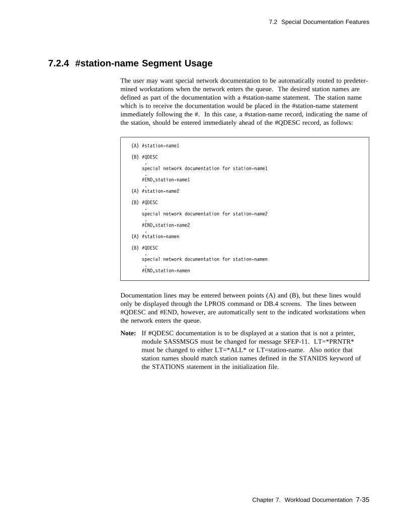
7.2 Special Documentation Features
7.2.4 #station-name Segment Usage
The user may want special network documentation to be automatically routed to predeter-mined workstations when the network enters the queue. The desired station names aredefined as part of the documentation with a #station-name statement. The station namewhich is to receive the documentation would be placed in the #station-name statementimmediately following the #. In this case, a #station-name record, indicating the name ofthe station, should be entered immediately ahead of the #QDESC record, as follows:
(A) #station-name1
(B) #QDESC
.
special network documentation for station-name1
.
#END,station-name1
.
(A) #station-name2
(B) #QDESC
.
special network documentation for station-name2
.
#END,station-name2
.
(A) #station-namen
(B) #QDESC
.
special network documentation for station-namen
.
#END,station-namen
Documentation lines may be entered between points (A) and (B), but these lines wouldonly be displayed through the LPROS command or DB.4 screens. The lines between#QDESC and #END, however, are automatically sent to the indicated workstations whenthe network enters the queue.
Note: If #QDESC documentation is to be displayed at a station that is not a printer,module SASSMSGS must be changed for message SFEP-11. LT=*PRNTR*must be changed to either LT=*ALL* or LT=station-name. Also notice thatstation names should match station names defined in the STANIDS keyword ofthe STATIONS statement in the initialization file.
Chapter 7. Workload Documentation 7-35
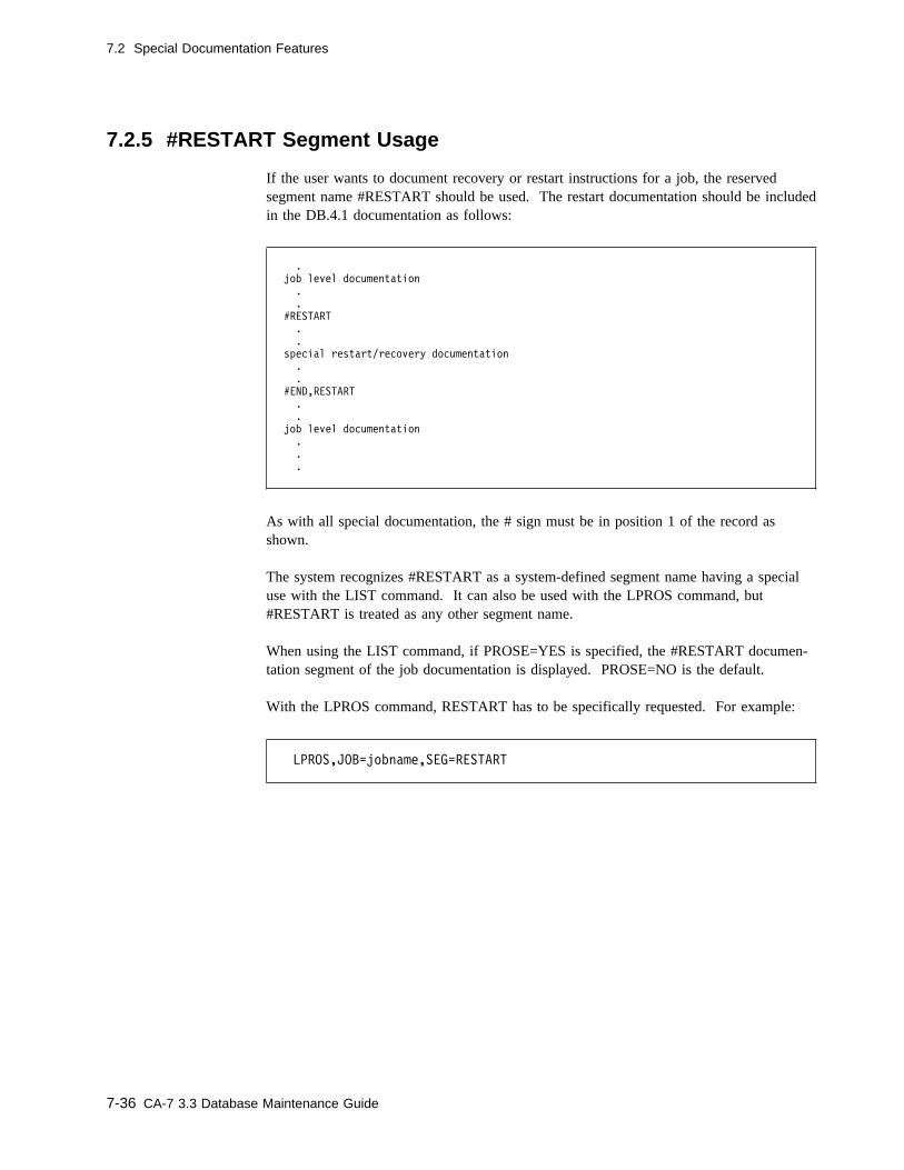
7.2 Special Documentation Features
7.2.5 #RESTART Segment Usage
If the user wants to document recovery or restart instructions for a job, the reservedsegment name #RESTART should be used. The restart documentation should be includedin the DB.4.1 documentation as follows:
.
job level documentation
.
.
#RESTART
.
.
special restart/recovery documentation
.
.
#END,RESTART
.
.
job level documentation
.
.
.
As with all special documentation, the # sign must be in position 1 of the record asshown.
The system recognizes #RESTART as a system-defined segment name having a specialuse with the LIST command. It can also be used with the LPROS command, but#RESTART is treated as any other segment name.
When using the LIST command, if PROSE=YES is specified, the #RESTART documen-tation segment of the job documentation is displayed. PROSE=NO is the default.
With the LPROS command, RESTART has to be specifically requested. For example:
LPROS,JOB=jobname,SEG=RESTART
7-36 CA-7 3.3 Database Maintenance Guide
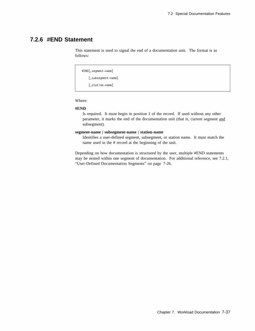
7.2 Special Documentation Features
7.2.6 #END Statement
This statement is used to signal the end of a documentation unit. The format is asfollows:
#END[,segment-name]
[,subsegment-name]
[,station-name]
Where:
#ENDIs required. It must begin in position 1 of the record. If used without any otherparameter, it marks the end of the documentation unit (that is, current segment andsubsegment).
segment-name | subsegment-name | station-nameIdentifies a user-defined segment, subsegment, or station name. It must match thename used in the # record at the beginning of the unit.
Depending on how documentation is structured by the user, multiple #END statementsmay be nested within one segment of documentation. For additional reference, see 7.2.1,“User-Defined Documentation Segments” on page 7-26.
Chapter 7. Workload Documentation 7-37

7-38 CA-7 3.3 Database Maintenance Guide
Chapter 8. Workstation Networks
This chapter describes setting up and maintaining a workstation network within CA-7.
Chapter 8. Workstation Networks 8-1
8.1 Adding a Network
8.1 Adding a Network
Adding a network is similar to adding a job. The primary method is to use the ADDfunction on the DB.5 screen. For new users or users making multiple changes to theirnetworks, other methods can be used.
If the network information already exists in machine-readable form, then writing aprogram to produce batch terminal network commands may be an advantage. The data-base can then be updated using the Batch Terminal Interface (BTI) facility. For furtherdetails on BTI, see 1.5, “Batch Input” on page 1-22 and the CA-7 Interfaces Guide.
Some items to remember when adding a network are:
1. On the DB.5 screen, stations must be defined in the chronological order in whichthey are used.
2. The DMDNW and RUNNW commands do not add a network to the database. Thesecommands require that the network be defined in the database with some type ofschedule before the commands can act on the network.
3. Input networks can be connected to one or more CPU jobs, in which case, they havea predecessor/dependency relationship with those jobs. These connections aredefined using the DB.3.4 screen functions.
4. Input networks which are not to be handled on an on-request basis must have acalendar-based schedule defined. This is done with the DB.2.2 screen.
5. Output networks are scheduled to be run because of their connection to a job. Whenthe connected CPU job is scheduled into the queue, the output network is broughtinto the postprocess queue.
6. Output networks must be logically connected with the DB.3.4 screen. Schedulingparameters must be entered through the DB.2.3 screen, but the schedule is notresolved against a calendar.
8-2 CA-7 3.3 Database Maintenance Guide

8.2 DB.5 - Input/Output Network Definition Screen
8.2 DB.5 - Input/Output Network Definition Screen
Use this screen to define networks of workstations at which manual tasks are performed.
� �
------------------- CA-7 INPUT/OUTPUT NETWORK DEFINITION -------------------
FUNCTION: xxxxxxxx (ADD,DELETE,FORMAT,LIST,UPD)
NETWORK: xxxxxxxx TYPE: xxxxxx
SUB-ID: xxxxxxxx JOB: xxxxxxxx SCHD PROSE: xxxxxxxx
STATION 1: xxxxxxxx
STATION 2: xxxxxxxx
STATION 3: xxxxxxxx
STATION 4: xxxxxxxx
STATION 5: xxxxxxxx
STATION 6: xxxxxxxx
STATION 7: xxxxxxxx
STATION 8: xxxxxxxx
STATION 9: xxxxxxxx
PROGRAM: SM4� MSG-INDX: nn -- DB.5 -- yy.ddd / hh:mm:ss
MESSAGE:
( )
To display, enter:
� 5 as the FUNCTION on the DB Menu screen.� DB.5 as the FUNCTION value on any other menu or formatted input screen.� DB.5 or NETWORK as a top line command.
To exit:
� Press the PF3 key to return to the DB Menu screen except with the TSO-ISPF inter-face when PF3 has been assigned to some other function.
� Move the cursor to the top line of the screen and enter the desired top line commandif yet another function is desired.
Chapter 8. Workstation Networks 8-3
8.2 DB.5 - Input/Output Network Definition Screen
8.2.1.1 Field Descriptions
FUNCTION: The function to be performed. Value must be the name of some otherscreen or one of the following:
ADD Adds a network to the database.DELETE Deletes a network, and its associated documentation and
schedules, from the database.
Note: A network cannot be deleted if it is connected toa job.
FORMAT Clears the screen of all user input data.LIST Lists the database information. In batch, a formatted
screen is not listed; only a found or not found message isreturned.
UPD Updates network information in the database.
Required: YesBatch keyword: Positional parameter
NETWORK: The network on which the indicated function is to be performed.Must be a network name.
Size/Type: 1 to 8 alphanumeric charactersRequired: YesBatch keyword: Positional parameter
TYPE: The value must be INPUT or OUTPUT to indicate the type ofnetwork.
Required: Yes - for ADD and UPD functionsNo - for DELETE, FORMAT, and LIST functions
Batch keyword: Positional parameter
SUB-ID: Used for further description of the network's duties.
Size/Type: 1 to 8 alphanumeric charactersRequired: NoBatch keyword: SUBID
Output Networks: SUBID should be specified on the DB.3.4 con-nection. Then, this sub-ID is shown on subsequent inquiries.
Input Networks: The SUBID specified here shows on variousinquiries. For example, if handling of input data is required for thenetwork, the user's task number, job number, or control number forthe data may be defined as the sub-ID.
8-4 CA-7 3.3 Database Maintenance Guide
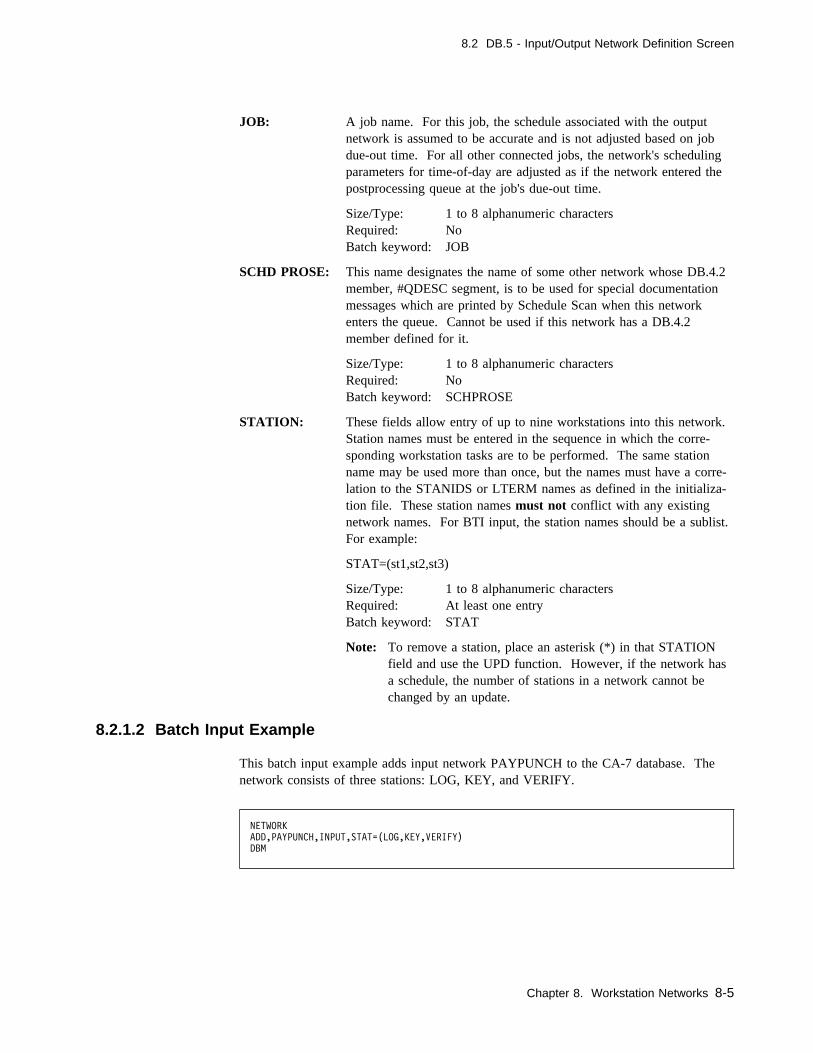
8.2 DB.5 - Input/Output Network Definition Screen
JOB: A job name. For this job, the schedule associated with the outputnetwork is assumed to be accurate and is not adjusted based on jobdue-out time. For all other connected jobs, the network's schedulingparameters for time-of-day are adjusted as if the network entered thepostprocessing queue at the job's due-out time.
Size/Type: 1 to 8 alphanumeric charactersRequired: NoBatch keyword: JOB
SCHD PROSE: This name designates the name of some other network whose DB.4.2member, #QDESC segment, is to be used for special documentationmessages which are printed by Schedule Scan when this networkenters the queue. Cannot be used if this network has a DB.4.2member defined for it.
Size/Type: 1 to 8 alphanumeric charactersRequired: NoBatch keyword: SCHPROSE
STATION: These fields allow entry of up to nine workstations into this network.Station names must be entered in the sequence in which the corre-sponding workstation tasks are to be performed. The same stationname may be used more than once, but the names must have a corre-lation to the STANIDS or LTERM names as defined in the initializa-tion file. These station names must not conflict with any existingnetwork names. For BTI input, the station names should be a sublist.For example:
STAT=(st1,st2,st3)
Size/Type: 1 to 8 alphanumeric charactersRequired: At least one entryBatch keyword: STAT
Note: To remove a station, place an asterisk (*) in that STATIONfield and use the UPD function. However, if the network hasa schedule, the number of stations in a network cannot bechanged by an update.
8.2.1.2 Batch Input Example
This batch input example adds input network PAYPUNCH to the CA-7 database. Thenetwork consists of three stations: LOG, KEY, and VERIFY.
NETWORK
ADD,PAYPUNCH,INPUT,STAT=(LOG,KEY,VERIFY)
DBM
Chapter 8. Workstation Networks 8-5
8.3 Changing a Network
8.3 Changing a Network
You should use the UPD function on the DB.5 screen if the characteristics of the networkare changing from that shown on the DB.5 screen. If there are many changes, you canmake these changes by using the Batch Terminal Interface (BTI) facility. For furtherdetails on BTI, see 1.5, “Batch Input” on page 1-22 and the CA-7 Interfaces Guide. Inmost cases, reconnecting the network may not be necessary, but the schedule may bedifferent. Be sure to consider the schedule function for this particular network. You canuse the DB.2 scheduling screens for this purpose.
If the function of the network changes, the job connections for that network may alsochange. In this case, you can use the DB.3.4 or DB.3.5 screen to redefine the job con-nections.
Keep in mind that one network can be connected to more than one CPU job and schedulechanges may be associated with the change of network function. Use theLNTWK,NW=networkname,LIST=USERS command to determine which jobs are con-nected to the network.
If the number of stations in a network changes, the stations cannot be added or deleted ifthe network has a schedule. The schedule must first be deleted.
8-6 CA-7 3.3 Database Maintenance Guide

Chapter 9. Data Sets
This chapter contains instructions for adding and maintaining data set information inCA-7.
Chapter 9. Data Sets 9-1

9.1 Adding a Data Set
9.1 Adding a Data Set
There are several methods of adding data sets to the database. The primary method isaccomplished through the LOAD process. When a job is loaded, all data set names refer-enced in the JCL are added to the database if those names are not already in the database.If the LOADDSNS keyword is used on the DBASE statement in the initialization file,then the LOAD process does not build any DD or data set information for jobs that aremarked MAINT=Y on the DB.1 (JOB) screen.
Data sets can also be added to the database by using the DB.6 screen ADD function.
If data set information already exists in machine-readable form, a program can be writtento perform the DB.6 screen functions with batch commands and the Batch Terminal Inter-face (BTI) facility. For further details on BTI, see 1.5, “Batch Input” on page 1-22 andCA-7 Interfaces Guide.
Once a data set is added to the database, CA-7 assigns a unique 6-digit number to thedata set, referred to as a DSNBR. The data set can then be referenced by that number.This eliminates the need to enter a long data set name each time the data set is to bereferenced by CA-7 commands and screens.
9-2 CA-7 3.3 Database Maintenance Guide
9.1 Adding a Data Set
9.1.1 Permanent Data Sets
During the LOAD process, any data set that is used as input to the job is considered arequirement for that job. This means that a new version of the data set must be createdbefore that job can be submitted by CA-7. Some data sets, however, are not created by aCA-7 submitted job. The user may wish these data sets to be considered as permanent toCA-7.
The LOAD process automatically adds data sets to the database and marks them perma-nent when all of the following conditions are true:
� Data set name does not already exist in the database.� Data set is normal data set (that is, not temporary, SYSIN, or SYSOUT).� Data set is accessed using a reserved ddname:
STEPLIB SORTLIB JOBLIB STEPCAT JOBCAT SYSUDUMP SYSABEND SYSMDUMP SYSCHK SYSCKEOV
Reserved ddnames reside in the SASSPMDD table. Names can be added or deletedas necessary to satisfy the needs of the user. See the topic Reserved DDNAMETable in the "User Exits and Modifications" chapter of the CA-7 Systems Pro-grammer Guide for a discussion of modifying this table.
The TYPE field on the DB.6 screen must be set to PERM for permanent data sets toCA-7. This must be done manually in those cases where the LOAD process could notdetermine that the data set was permanent. When the data set is defined as permanent, itis not considered to be a requirement for any job that uses it as input.
Chapter 9. Data Sets 9-3

9.1 Adding a Data Set
9.1.2 Dynamically Allocated Data Sets
Data sets which are dynamically allocated by the program(s) and do not have a DD state-ment in the JCL must be defined with the DB.6 screen. The LOAD process cannotperform this function since a DD statement was not used.
9.1.3 External Data Sets
Data sets can be defined as preexecution requirements for jobs even though the data set isnever created or referenced by any job running under CA-7's control. Such data sets arereferred to as external data sets and must be defined using the DB.6 screen. Data setswhich are used by jobs under CA-7's control but are never created with a DISP=NEW arealso referred to as external data sets. These data sets can be defined as job requirementsusing the DB.3.1 screen, but the requirements must be satisfied by the user before thedependent job can execute. Requirement posting can be performed using online screens,batch terminal interface commands, Trailer Step commands, or U7SVC input.
9-4 CA-7 3.3 Database Maintenance Guide

9.2 DB.6 - Data Set Definition Screen
9.2 DB.6 - Data Set Definition Screen
Use this screen to define a user data set to CA-7.
Normally, you use this screen to define data sets with a TYPE value of PERM or forupdates. If this screen is not used to define a data set, the initial LOAD of the job addsthe data set to the database automatically. You can also perform any manual maintenancerequired on this information with this screen.
� �
------------------------- CA-7 DATA SET DEFINITION -------------------------
FUNCTION: xxxxxxxx (ADD,DELETE,FORMAT,LIST,RENAME,UPD)
DSN: xxxxxxxxxxxxxxxxxxxxxxxxxxxxxxxxxxxxxxxxxxxx DSNBR: nnnnnn
NEWNAME: xxxxxxxxxxxxxxxxxxxxxxxxxxxxxxxxxxxxxxxxxxxx
TYPE: xxxx GDG: x
SMF FEEDBACK REQUIRED: x POST AT CLOSE TIME: x
DEVICE: xxxx
DSORG: xxx
RECFM: xxxxx
LRECL: nnnnn
BLKSIZE: nnnnn
PROGRAM: SM3� MSG-INDX: nn -- DB.6 -- yy.ddd / hh:mm:ss
MESSAGE:
( )
To display, enter:
� 6 as the FUNCTION on the DB Menu screen.� DB.6 as the FUNCTION value on any other menu or formatted input screen.� DB.6 or DSN as a top line command.
To exit:
� Press the PF3 key to return to the DB Menu screen except with the TSO-ISPF inter-face when PF3 has been assigned to some other function.
� Move the cursor to the top line of the screen and enter the desired top line commandif yet another function is desired.
Chapter 9. Data Sets 9-5

9.2 DB.6 - Data Set Definition Screen
9.2.1.1 Field Descriptions
FUNCTION: The function to be performed. Value must be the name of some otherscreen or one of the following:
ADD Adds a data set to the database.
DELETE Deletes a data set and its associated elements (data settriggers, user documentation, and so forth).
Note: If any job uses this data set, it cannot be deleteduntil the jobs or their DSN predecessor require-ments are deleted.
FORMAT Clears the screen of all user input data.
LIST Lists the formatted data of the screen. In batch, a for-matted screen is not listed; only a found or not foundmessage is returned.
RENAME When the user has changed a data set's name, RENAMEwith the NEWNAME field may be used to change theCA-7 data set name. The RENAME top line utilitycommand changes the data set name in OS; whereas, theRENAME function on this screen changes the data setname in the CA-7 database, but not in OS.
UPD Updates data set information in the database.
Required: YesBatch keyword: Positional parameter
DSN: Identifies the data set and must be the fully qualified data set name.
Size/Type: 1 to 44 alphanumeric charactersRequired: Yes - for ADD (and UPD unless DSNBR is used)Batch keyword: DSN
Note: CA-7 does not support DSNs with embedded blanks in thename, or any other nonconventional data set name.
DSNBR: Identifies the data set to be used and must be the numeric valuealready assigned by CA-7.
Size/Type: 1 to 6 numeric characters (leading zeros notrequired)
Required: Yes - unless DSN is used (ignored for ADD)Batch keyword: DSNBR
9-6 CA-7 3.3 Database Maintenance Guide

9.2 DB.6 - Data Set Definition Screen
NEWNAME: Used with the RENAME function and DSN field to change a data setname in the CA-7 database. The RENAME top line utility commandchanges the data set name in OS; whereas, the RENAME function onthis screen changes the data set name in the CA-7 database, but not inOS.
Size/Type: 1 to 44 alphanumeric charactersRequired: NoBatch keyword: NEWNAME
TYPE: Indicates the data set type. Value can be:
NORM Internal: Both the creating-job and using-jobs for this dataset are known to CA-7.
External: The creating-job and/or using-job(s) for this dataset is not known to CA-7.
PERM This data set is always available for input. See 9.1.1, “Per-manent Data Sets” on page 9-3.
Note: When a data set is marked PERM, no SMF recordsare captured, so no data set triggering can occur withthis type data set.
Default: NORM when doing ADDRequired: NoBatch keyword: TYPE
GDG: Indicates whether this data set is a generation data group (Y or N).
Default: NRequired: NoBatch keyword: GDG
Note: Specific GDG creations cannot be used for posting require-ments or for triggering jobs. Posting and triggering are donebased on the creation/updating (SMF 15 record) of any gener-ation of the GDG.
SMF FEEDBACK REQUIRED:Indicates whether the interface to System Management Facility (SMF)should insert the values for DSORG, RECFM, LRECL and BLKSIZEwhen this data set is next used (Y or N). Unless reset, this insertionis only done once.
Default: YRequired: NoBatch keyword: SMF
Chapter 9. Data Sets 9-7
9.2 DB.6 - Data Set Definition Screen
Note: After the first time the job that creates this data set runs underCA-7, this field is reset to N. Should the data set attributeschange, this field must be reset to Y and the attribute field thatchanged (that is, DSORG, RECFM) must be zeroed (ifnumeric) or blanked out. This causes CA-7 to record the newvalues when the job is run again.
POST AT CLOSE TIME:Indicates when to post the creation or update of a data set to the data-base and queues (Y or N). If Y is specified, action takes place assoon as the SMF data set creation record is received (when the dataset is closed). This does not guarantee successful step or job termi-nation.
Size/Type: Y or NDefault: N (causes triggering or posting action to take place
at job termination)Required: NoBatch keyword: POST
DEVICE: Indicates device type. If specified, TAPE or DASD are the onlyacceptable values.
Required: NoBatch keyword: DEVICE
DSORG: Indicates the data set organization. Same as the DSORG specified inthe DCB subparameter in the JCL.
Size/Type: 1 to 3 alphanumeric charactersRequired: NoBatch keyword: DSORG
RECFM: Indicates the record format of the data set. Same as the RECFMspecified in the DCB subparameter in the JCL.
Size/Type: 1 to 5 alphanumeric charactersRequired: NoBatch keyword: RECFM
LRECL: Indicates the logical record length of the data set. Same as theLRECL specified in the DCB subparameter in the JCL.
Size/Type: 1 to 5 numeric charactersRequired: NoBatch keyword: LRECL
BLKSIZE: Indicates the block size of the data set. Same as the BLKSIZE speci-fied in the DCB subparameter in the JCL.
Size/Type: 1 to 5 numeric charactersRequired: NoBatch keyword: BLKSIZE
9-8 CA-7 3.3 Database Maintenance Guide

9.2 DB.6 - Data Set Definition Screen
9.2.1.2 Usage Notes
You can maintain connections to jobs that require this data set using the DB.3.1 screen.
9.2.1.3 Batch Input Example
This batch input example adds data set SYS2.PROCLIB to the CA-7 database as a per-manent type.
DBM
DSN
ADD,DSN=SYS2.PROCLIB,TYPE=PERM
DBM
Chapter 9. Data Sets 9-9

9.3 Changing a Data Set
9.3 Changing a Data Set
The DB.6 screen is used to change the characteristics of a data set by entering the UPDfunction and the changed field values.
One of the more common uses of this screen is that of renaming data sets. If the DCBfor this data set is not changing, all that needs to be entered is the RENAME functionand the NEWNAME for the data set. This changes the data set name in the CA-7 data-base. To change the data set name in OS, use the RENAME top line utility command.
If DCB attributes change, be sure that the SMF indicator has the proper value for thesituation. If the system is to automatically pick up the DCB characteristics, the SMFindicator should be set to Y and the appropriate DCB field cleared to blanks or zeros.
Note: RENAME should occur before changing JCL and LOADing of jobs; otherwise,DB.3.1 updates may need to be manually performed to disconnect the old data setname.
9-10 CA-7 3.3 Database Maintenance Guide
Chapter 10. JCL Management
This chapter identifies the screens and commands used to manage JCL within CA-7. Italso includes discussion of JCL validation, overrides, LOAD command processing, theSASSJCLU utility program, and use of alternate libraries.
Chapter 10. JCL Management 10-1

10.1 DB.7 - JCL Library Maintenance Screen
10.1 DB.7 - JCL Library Maintenance Screen
Use this screen to enter or review JCL statements in PDS or sequential JCL libraries. Itcan also be used to review CA-Librarian or CA-Panvalet JCL.
� �
----------------------- CA-7 JCL LIBRARY MAINTENANCE -----------------------
FUNCTION xxxxxxxx (APPEND,CLEAR,DELETE,EDIT,FE,FETCH,
RENAME,REPL,RUN,RUNH,SAVE)
MEMBER xxxxxxxx NEWNAME/OPTION: xxxxxxxx
DSN xxxxxxxxxxxxxxxxxxxxxxxxxxxxxxxxxxxxxxxxxxxx JCL-ID: nnn
VOLSER xxxxxx JCLLIB: &xxxxxxxxxxxxxxx
ACTIVE SIZE nnnn
PROGRAM SM5� MSG-INDX: nn -- DB.7 -- yy.ddd / hh:mm:ss
MESSAGE
( )
To display, enter
� 7 as the FUNCTION on the DB Menu screen.� DB.7 as the FUNCTION on any other menu or formatted input screen.� DB.7 or JCL as a top line command.
To exit
� Press the PF3 key to return to the DB Menu screen except with the TSO/ISPF inter-face when PF3 has been assigned to some other function.
� Move the cursor to the top line of the screen and enter the desired top line commandif yet another function is desired.
10-2 CA-7 3.3 Database Maintenance Guide

10.1 DB.7 - JCL Library Maintenance Screen
10.1.1 Field Descriptions
FUNCTION: The function to be performed. Value must be the name of some otherscreen or one of the following:
APPEND Attaches card-image data to the end of any existing linesin the terminal's Active Area.
CLEAR Clears screen input data fields and clears the user'sActive Area.
DELETE Deletes a member from a PDS.
EDIT transfers the user to the edit facility and allows text proc-essing. See Chapter 11, “Edit Facility” on page 11-1and following subtopics for a discussion of the availablecommands for processing the desired text.
FE Combination of FETCH and EDIT.
FETCH Retrieves data and replaces the user's Active Area withthis text.
RENAME Used with the NEWNAME field to rename a PDSmember.
REPL Replaces a PDS member or sequential data set with thecontents of the Active Area.
RUN Submits the text editor Active Area to the defaultMAINID without verifying the input requirements orperforming the updates which normally follow successfuljob completion. Job start and job end messages arereceived at the issuing terminal where RUN was entered.Jobs scheduled with this function always show a due-outdate and time of 69001/0000. If a /*PRIORITY state-ment is found as the first statement being submitted bythis function, the statement is ignored and not submitted.
Note: The SASSXX05 exit is invoked for each JCLstatement. Also, if there is a job in the CA-7database with this member name and it is set toinsert the CA-11 RMS step and the CA-11 inter-face is installed, the RMS step is inserted.
RUNH Same action as RUN function except this job is placed inCA-7 hold status.
Chapter 10. JCL Management 10-3

10.1 DB.7 - JCL Library Maintenance Screen
SAVE Adds a new PDS member or replaces a sequential dataset with the contents of the Active Area.
Note: The SAVE or REPL function cannot be performed onCA-Librarian or CA-Panvalet files.
Required: YesBatch keyword: Positional parameter
MEMBER: For PDS, CA-Panvalet, or CA-Librarian access, the required membername. Must be omitted for sequential files.
Size/Type: 1 to 8 alphanumeric charactersRequired: YesBatch keyword: Positional parameter
NEWNAME/OPTION:Multiple purpose field. Required with the RENAME function to indi-cate the new name which is to replace the old name.
Size/Type: 1 to 8 alphanumeric charactersDefault: BlankRequired: Yes for RENAME function onlyBatch keyword: NEWNAME
Note: For CA-Librarian or CA-Panvalet data set functions, a value ofN indicates that include statements are not to be expanded.Default causes those statements to be expanded.
DSN: The optional data set name. When reviewing a member of a PDS,CA-Panvalet, or CA-Librarian file, DSN is not needed if JCLID isspecified. If the data set is cataloged, DSN is sufficient. If the dataset is not cataloged, DSN must be specified with the VOLSER fieldbelow.
Size/Type: 1 to 44 alphanumeric charactersRequired: NoBatch keyword: DSN
JCL-ID: JCL library identification. Can be used instead of DSN and VOLSERfields to refer to a JCL statement. Must be a numeric INDEXassigned to a JCL statement. JCL-ID and JCLLIB are mutually exclu-sive.
Size/Type: 1 to 3 numeric characters from 0 to 254. A valueof 255 is reserved for symbolic indexes. SeeJCLLIB.
Default: Value is obtained from the corresponding job entryin the database if it exists. Otherwise, the default is0 (if DSN and VOLSER are omitted).
Required: NoBatch keyword: JCLID
10-4 CA-7 3.3 Database Maintenance Guide
10.1 DB.7 - JCL Library Maintenance Screen
JCLLIB JCL library identification. Can be used instead of DSN and VOLSERfields to refer to a JCL statement. Must be a symbolic INDEXassigned to a JCL statement. JCLLIB and JCL-ID are mutually exclu-sive.
Size/Type: 2 to 16 alphanumeric characters beginning with anampersand (&). The value &HELP is reserved.
Default: BlankRequired: NoBatch keyword: JCLLIB
VOLSER: Indicates the volume serial number on which the data set resides.Only used with DSN above. The volume must be available to CA-7.
Size/Type: 1 to 6 alphanumeric charactersRequired: NoBatch keyword: VOL
ACTIVE SIZE: A system-generated field which tells the user how many lines exist inthe Active Area for the current terminal session.
Note: CA-Panvalet, CA-Librarian, and PDS data sets require a JCLdefinition in the initialization file and in the execution JCL forCA-7.
When EDIT or FE is entered, the user is transferred to the editfacility. See Chapter 11, “Edit Facility” on page 11-1 for acomplete description of this feature.
10.1.2 Usage Notes
A shortcut method of displaying a specific job is to enter JCL,jobname as a top linecommand.
You can use this screen to access any card-image PDS, CA-Librarian, CA-Panvalet, orsequential file which is on a DASD volume available to CA-7.
If a SAVE/REPL is done for a member name that matches a job name in the CA-7 data-base, and the specified DSN library is a CA-7 JCL data set, then the job is flagged forreload on the next run. However, if RELOAD of N is used on the DB.1 (JOB) screen,then the RELOAD on the next run is ignored.
Chapter 10. JCL Management 10-5
10.2 Scheduled Overrides
10.2 Scheduled Overrides
CA-7 provides the ability to schedule JCL overrides. Scheduled overrides may consist ofany statement that may be included with the JCL for a job, not just JCL statements.Some special purpose statements, described later in this chapter, and any JCL orembedded data records can be scheduled. This enables users to have the run stream con-tents dynamically constructed to fit the needs of any particular run.
Overrides may be scheduled to be used:
� on specific dates� after specific dates� before specific dates� between specific dates� only after a certain time-of-day� only before a certain time-of-day� with specific schedule IDs� within a range of schedule IDs� only when CA-7/RPT is up or down
This enables users to prepare the proper statements anytime in advance of their needswithout having to remember them on the day(s) they are needed. This also enables usersto ensure that they are used only on the appropriate day(s).
Scheduled overrides are placed in the execution JCL members. They cannot be used inPROCLIB members since CA-7 does not access those members directly. The statementsto be scheduled are placed in the JCL wherever they belong and are bookended withspecial reserved CA-7 control statements. One special statement is placed immediatelyahead of the statements to define the scheduling criteria and another special statement isplaced at the end of the set to mark the end of the statements being scheduled. Multiplesets may be included within a single job. All sets must be located after the JOB state-ment.
The first special statement of each set indicates the scheduling criteria and whether theother statements in the set are to be included or omitted based on those criteria. Thesespecial statements are identified by the characters #JI, #JO, #XI, or #XO in positions 1-3of the statement. Also, these statements cannot be continued.
10-6 CA-7 3.3 Database Maintenance Guide

10.2 Scheduled Overrides
10.2.1 #JI and #JO Statements
10.2.1.1 Syntax
#JI #JO
WW─ ──┬ ┬─#JI─ ──┬ ┬──────────────────────── ──┬ ┬───────────────── ──────W └ ┘─#JO─ │ │┌ ┐─���────────── │ │┌ ┐─�����─
└ ┘──,ID= ──┼ ┼─BAT────────── └ ┘──,BD= ──┴ ┴─yyddd─ ├ ┤─nnn────────── ├ ┤─nnn-nnn────── └ ┘─(nnn,...nnn)─
W─ ──┬ ┬──────────────── ──┬ ┬───────────────── ──┬ ┬──────────────── ────W │ │┌ ┐─����─ │ │┌ ┐─99999─ │ │┌ ┐─24��─
└ ┘──,BT= ──┴ ┴─hhmm─ └ ┘──,ED= ──┴ ┴─yyddd─ └ ┘──,ET= ──┴ ┴─hhmm─
W─ ──┬ ┬────────────── ──┬ ┬────────────── ──┬ ┬──────────────── ─────────W└ ┘──,JOB=jobname │ │┌ ┐─N─ │ │┌ ┐─����─
└ ┘──,RPT= ──┴ ┴─Y─ └ ┘──,OA= ──┴ ┴─hhmm─
W─ ──┬ ┬──────────────── ──┬ ┬────────────── ──────────────────────────Wc │ │┌ ┐─24��─ │ │┌ ┐─DO─
└ ┘──,OB= ──┴ ┴─hhmm─ └ ┘──,CV= ──┼ ┼─DL─ └ ┘─CU─
Where:
#JIIndicates the statements are to be included based on the specified scheduling criteria.
#JOIndicates the statements are to be omitted based on the specified scheduling criteria.
IDIndicates a schedule ID number. If the job is scheduled by this ID, this test forstatement inclusion or exclusion is considered true.
Default: 000Required: No
000All schedule IDs.
nnnIndicates a specific schedule ID.
nnn-nnnIndicates a range of schedule IDs. If the job is scheduled by either of the twoIDs specified or any ID between those two IDs, this test is considered true.
(nnn,...,nnn)Indicates a list of IDs, either specific or ranges, separated by commas andenclosed within parentheses. If any test in the list is true, statements areincluded or excluded based on the type of statement used.
Chapter 10. JCL Management 10-7
10.2 Scheduled Overrides
BDIndicates a beginning date after which the overrides are in effect.
Size/Type: 5 numeric characters Julian date specified as yydddDefault: 00000Required: No
BTIndicates a beginning time-of-day for the BD date.
Size/Type: 4 numeric characters specified as hhmmDefault: 0000Required: No
EDIndicates an ending date after which the overrides are no longer in effect.
Size/Type: 5 numeric characters Julian date specified as yydddDefault: 99999Required: No
ETIndicates an ending time-of-day for the ED date.
Size/Type: 4 numeric characters specified as hhmmDefault: 2400Required: No
JOBIndicates that inclusion/exclusion is to be based on a matching fully qualified jobname.
Size/Type: 1 to 8 alphanumeric charactersRequired: No
RPTIndicates that inclusion/exclusion is to be based on the presence (Y) or absence (N)of CA-7/RPT.
Default: Y (If SUBSYS=RPT is coded in the DBASE statement in the CA-7initialization file and CA-7/RPT is active)
Required: No
OAIndicates a time-of-day only at which and after which the overrides are to be consid-ered for inclusion or exclusion. The OA time should be lower than the OB timespecified.
Size/Type: 4 numeric characters specified as hhmmDefault: 0000Required: No
10-8 CA-7 3.3 Database Maintenance Guide
10.2 Scheduled Overrides
OBIndicates a time-of-day only at which and before which the overrides are to be con-sidered for inclusion or exclusion.
Size/Type: 4 numeric characters specified as hhmmDefault: 2400Required: No
CVIndicates the comparison values against which BD, BT, ED, ET, OA, and OB param-eters are to be compared.
Default: DORequired: No
DOIndicates values specified are to be compared against the due out date and thetime-of-day values.
DLIndicates values specified are to be compared against the deadline date and thetime-of-day values.
CUIndicates values specified are to be compared against the current date and thetime-of-day values.
The ID, BD, BT, ED, ET, RPT, OA, OB, and CV parameters may be used in combi-nation to accomplish the desired result. At least one of the parameters must be used.
Note: The default date and time used for the test for exclusion or inclusion is the job'sdue out time unless otherwise specified on the CV parameter. That is, if the dueout time for the job falls within the beginning and ending date and time, the state-ments are excluded or included. The due out time for a demanded job is thecurrent time plus one hour unless otherwise specified on the CV parameter orspecified differently with the DOTM and/or LEADTM on the DEMANDcommand. When using JCL validation to test these statements, the time used isalways the current time since due-out and deadline times are not applicable.
If any errors are encountered in the #JI or #JO override statements (that is, invaliddata for ID, BD, BT, ED, ET, RPT, OA, OB, or CV fields), a message is sentnotifying the MASTER station that the JCL could not be attached, and the jobremains in the request queue in SKELETON status.
The first statement in any JCL member must be a JOB statement and may not beoverridden. The exception is a /*PRIORITY statement which may precede theJOB statement. However, #JI and #JO statements must come after the JOB state-ment.
Chapter 10. JCL Management 10-9
10.2 Scheduled Overrides
10.2.2 #JEND Statement
The conditional statements may be terminated by another #JO or #JI statement, an end-of-file, or a #JEND statement. The #JEND statement indicates the end of a set of ScheduledOverride control statements.
10.2.2.1 Syntax
#JEND
WW──#JEND─────────────────────────────────────────────────────────Wc
10.2.2.2 Usage Notes
There are no other keywords, and it must begin in position 1 of the statement.
Note: #JI, #JO, and #JEND statements are stripped out of the JCL, and overridesapplied, as the JCL for the job is brought into the queue. These statementscannot be seen in the JCL for the job in the queue, nor can they be added to thequeue JCL.
10.2.3 #XI, #XO, and #XEND Statements
If the user prefers # statements to remain until submission time, the characters #XI, #XO,and #XEND must be substituted for #JI, #JO, and #JEND respectively. The format andfield descriptions of the #XI, #XO, and #XEND statements are the same as the #JI, #JO,and #JEND statements. All scheduling parameters have the same meaning when eitherthe #X or #J statements are used. The only difference between #X and #J is that theoverrides are applied at submission time for the #X statements. If any errors are encount-ered in the #XI or #XO override statements at submission time, the job is flushed with anerror message.
Any time after the job enters the queues and prior to JCL submission, #X statements canbe reviewed and/or changed with the QM.5 screen.
10-10 CA-7 3.3 Database Maintenance Guide

10.2 Scheduled Overrides
10.2.4 Scheduled Override Examples
Example 1: To omit statements whenever a job is scheduled by Schedule ID 6, use:
#JO,ID=6
.
. (JCL statements to be omitted)
.
#JEND
Example 2: To include statements until date 00265 at 8.00 AM, use:
#JI,ED=��265,ET=�8��
.
. (JCL statements to be included)
.
#JEND
Example 3:
To omit statements from 00200 to 00206, use:
#JO,BD=��2��,ED=��2�6
.
. (JCL statements to be omitted)
.
#JEND
Example 4: To include statements from 00200 to 00206, use:
#JI,BD=��2��,ED=��2�6
.
. (JCL statements to be included)
.
#JEND
Example 5: To include statements whenever a job is scheduled by Schedule IDs 1, 4,5, 6, and 9, use:
#JI,ID=(1,4-6,9)
.
. (JCL statements to be included)
.
#JEND
Chapter 10. JCL Management 10-11
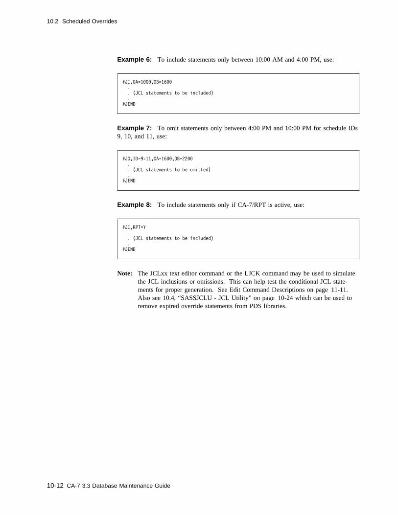
10.2 Scheduled Overrides
Example 6: To include statements only between 10:00 AM and 4:00 PM, use:
#JI,OA=1���,OB=16��
.
. (JCL statements to be included)
.
#JEND
Example 7: To omit statements only between 4:00 PM and 10:00 PM for schedule IDs9, 10, and 11, use:
#JO,ID=9-11,OA=16��,OB=22��
.
. (JCL statements to be omitted)
.
#JEND
Example 8: To include statements only if CA-7/RPT is active, use:
#JI,RPT=Y
.
. (JCL statements to be included)
.
#JEND
Note: The JCLxx text editor command or the LJCK command may be used to simulatethe JCL inclusions or omissions. This can help test the conditional JCL state-ments for proper generation. See Edit Command Descriptions on page 11-11.Also see 10.4, “SASSJCLU - JCL Utility” on page 10-24 which can be used toremove expired override statements from PDS libraries.
10-12 CA-7 3.3 Database Maintenance Guide
10.3 Additional Override Statements
10.3 Additional Override Statements
CA-7 also provides a number of other functions which can be accomplished with state-ments which also begin with a # in position 1. These statements may be located any-where within the execution JCL after the JOB statement. (PROCLIB members containingthese statements are not seen by CA-7 and including them there would thus serve nopurpose.) They may be scheduled with #Jx statements if desired; however, they may beincluded by themselves if conditional inclusion is not necessary. Only the #MSG state-ment may be scheduled with the #Xx statement.
The following statements may be placed in the execution JCL:
#ARF Overrides the ARFSET designation on the DB.1 screen when the JCL isattached for the job.
#HLD Places the job in HOLD. Similar to the HOLD command and the DB.1 screenHOLD option.
#JCL Sets a JCL override requirement.
#MNT Considers this run a maintenance type run. Similar to the DB.1 screen MAINToption.
#MSG Sends messages to the master station at job submission time. See 10.3.2,“#MSG Statement” on page 10-16.
#NOX Makes this run nonexecutable. Similar to the DB.1 screen EXEC option.
#NTR Turns off triggering by successful job completion for this run. Similar to theDEMAND command with SET=NTR option.
#RES Changes any Workload Balancing resource requirement for this run. Similar tothe RESCHNG command. See 10.3.3, “#RES Statement” on page 10-17 for adiscussion on the format and keywords.
#SCC Defines step-level condition code checking criteria. See the discussion of10.3.4, “#SCC Statement” on page 10-18.
#VER Sets manual verification requirement. Similar to the VERIFY command and theDB.1 screen VERIFY option.
#7UNI Flags JCL to be used to send work to Unicenter TNG. It must be the firststatement in the member and prevents edits from CA-7 unless Mixed CaseEditor support has been enabled.
Chapter 10. JCL Management 10-13

10.3 Additional Override Statements
10.3.1 #ARF Statement
Use the #ARF statement to override the ARFSET designation on the DB.1 screen whenthe JCL is attached for the job.
10.3.1.1 Syntax
#ARF
WW─ ──#ARF,SET=nnnnnnnn ────────────────────────────────────────────Wc
Where:
#ARFIdentifies the statement as an ARFSET override. #ARF must begin in position 1 ofthe record.
SETIdentifies the name of the ARFSET that is to be used for this run of the job.
10.3.1.2 Example
Suppose that the DB.1 screen for job A designates an ARFSET named ARECOVR to beused for ARF recovery.
The following example illustrates the use of the #ARF statement to override the ARFSETdesignation:
#ARF,SET=ABC
In this example, ARFSET ABC will be used to determine ARF recovery for this jobinstead of ARECOVR.
10-14 CA-7 3.3 Database Maintenance Guide
10.3 Additional Override Statements
10.3.1.3 Usage Notes
When a job initially enters the request queue, CA-7 determines whether ARF is tomonitor the job. CA-7 selects an ARFSET to be used for monitoring and recovery basedon the following hierarchy:
1. If an ARFSET is supplied on the DEMAND or RUN command, it will be used.
2. If no ARFSET is supplied on a DEMAND or RUN command for the job, then theARFSET named on the appropriate #ARF statement in the JCL will be used.
3. If no ARFSET is supplied on a DEMAND or RUN command for the job, and if noARFSET is named on a #ARF statement in the JCL, then the ARFSET named on theDB.1. screen will be used.
4. If none of the above sources supplies an ARFSET reference, then the job will not bemonitored by ARF.
Chapter 10. JCL Management 10-15

10.3 Additional Override Statements
10.3.2 #MSG Statement
#MSG statements may be used to send messages to the CA-7 Master Station at job sub-mission time. These statements must begin in column 1 and are placed in execution JCLmembers on the JCL libraries. The edit facility, with the JCL command of databasemaintenance, can be used to add these statements. The statements may appear withinscheduled overrides, in which case sending the messages is conditional.
10.3.2.1 Syntax
#MSG
WW─ ──#MSG,message-text ────────────────────────────────────────────Wc
10.3.2.2 Usage Notes
The message-text in columns 6 through 72 is sent immediately preceding the submitmessage. The actual #MSG statements are never included in the submitted JCL.
Note: The same rules for other # statements also apply to the #MSG statement.
10-16 CA-7 3.3 Database Maintenance Guide

10.3 Additional Override Statements
10.3.3 #RES Statement
You may place this statement in the execution JCL to make temporary changes to thehigh-water workload balancing resource requirements of the job.
10.3.3.1 Syntax
#RES
WW──#RES─ ──┬ ┬────────── ──┬ ┬────────── ──┬ ┬────────────── ────────────W └ ┘──,TP1=nnn └ ┘──,TP2=nnn └ ┘──,CPUTM=mmmss
W─ ──┬ ┬────────────── ──┬ ┬────────── ──┬ ┬────────── ──────────────────Wc└ ┘──,ELAPTM=hhmm └ ┘──,PRT=nnn └ ┘──,CLASS=x
Where:
TP1Indicates the number of tape drives of TYPE1 that are required of the job.
Size/Type: 1 to 3 numeric characters from 0 to 255Required: No
TP2Indicates the number of tape drives of TYPE2 that are required of the job.
Size/Type: 1 to 3 numeric characters from 0 to 255Required: No
CPUTMIndicates the amount of CPU time the job consumes in minutes and seconds.
Size/Type: 2 to 5 numeric characters specified as mmmss where mmm may befrom 0 to 999; seconds from 0 to 59
Required: No
ELAPTMIndicates the elapsed time required for the job.
Size/Type: 2 to 5 numeric characters specified as hhmm where hh can be from0 to 24; mm from 0 to 59
Required: No
PRTIndicates the initial priority value for the job.
Size/Type: 1 to 3 numeric characters from 0 to 255Required: No
CLASSIndicates the WLB job class of the job.
Size/Type: 1 alphanumeric characterRequired: No
Chapter 10. JCL Management 10-17

10.3 Additional Override Statements
10.3.4 #SCC Statement
These statements may be placed in the execution JCL to define step level condition codetests used to determine whether the job completed successfully.
10.3.4.1 Syntax
#SCC
WW─ ──#SCC,COND=(xxxx ──┬ ┬─────── ,ro, ──┬ ┬─C─────────────────── ) ─────Wc └ ┘──-yyyy ├ ┤─nnnnnnnn──────────── ├ ┤─jjjjjjjj.nnnnnnnn─── ├ ┤─�-nnnnnnnn────────── └ ┘─�-jjjjjjjj.nnnnnnnn─
Where:
#SCCIdentifies the statement as a step level condition code test. #SCC must begin inposition 1 of the record.
CONDIdentifies the following information as condition code test values.
xxxxIdentifies the condition code value to be tested against the actual value returnedat execution time. The entry must be numeric and fall within the range of 0 to4095.
A range of condition codes may be specified as xxxx-yyyy where xxxx is theminimum in the range of condition code values to be tested and yyyy is themaximum in the range of condition codes to be tested. Each entry must benumeric and fall within the range of 0 to 4095.
roIndicates the relational operator specifying the comparison to be made. If thecondition code value returned has the relationship defined by the ro entry, thestep value is unacceptable and the job is considered abnormally completed. Forexample, if ro is set to LT and xxxx is set to 8, the job is marked as completingabnormally if 8 is less than the return code from the step whose name matchesthe name in the nnnnnnnn parameter. The value must be one of the following:
GT Greater than
GE Greater than or equal to
EQ Equal to
LT Less than
LE Less than or equal to
NE Not equal to
FL Mark the job abnormally terminated if the named step was flushed
10-18 CA-7 3.3 Database Maintenance Guide
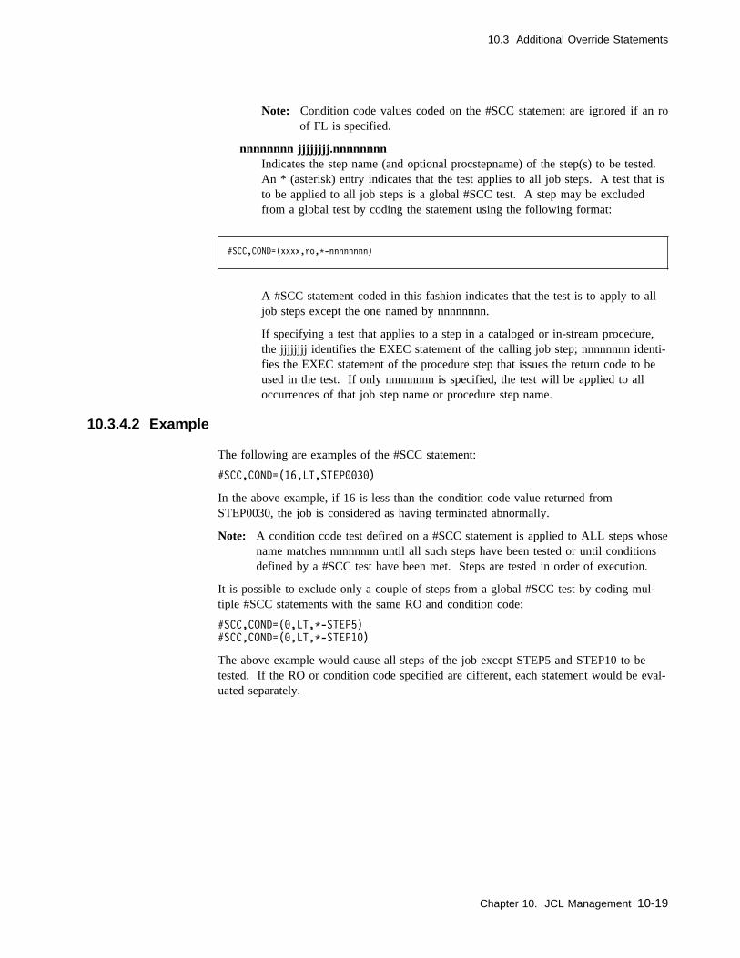
10.3 Additional Override Statements
Note: Condition code values coded on the #SCC statement are ignored if an roof FL is specified.
nnnnnnnn jjjjjjjj.nnnnnnnnIndicates the step name (and optional procstepname) of the step(s) to be tested.An * (asterisk) entry indicates that the test applies to all job steps. A test that isto be applied to all job steps is a global #SCC test. A step may be excludedfrom a global test by coding the statement using the following format:
#SCC,COND=(xxxx,ro,C-nnnnnnnn)
A #SCC statement coded in this fashion indicates that the test is to apply to alljob steps except the one named by nnnnnnnn.
If specifying a test that applies to a step in a cataloged or in-stream procedure,the jjjjjjjj identifies the EXEC statement of the calling job step; nnnnnnnn identi-fies the EXEC statement of the procedure step that issues the return code to beused in the test. If only nnnnnnnn is specified, the test will be applied to alloccurrences of that job step name or procedure step name.
10.3.4.2 Example
The following are examples of the #SCC statement:
#SCC,COND=(16,LT,STEP��3�)
In the above example, if 16 is less than the condition code value returned fromSTEP0030, the job is considered as having terminated abnormally.
Note: A condition code test defined on a #SCC statement is applied to ALL steps whosename matches nnnnnnnn until all such steps have been tested or until conditionsdefined by a #SCC test have been met. Steps are tested in order of execution.
It is possible to exclude only a couple of steps from a global #SCC test by coding mul-tiple #SCC statements with the same RO and condition code:
#SCC,COND=(�,LT,C-STEP5)
#SCC,COND=(�,LT,C-STEP1�)
The above example would cause all steps of the job except STEP5 and STEP10 to betested. If the RO or condition code specified are different, each statement would be eval-uated separately.
Chapter 10. JCL Management 10-19
10.3 Additional Override Statements
10.3.4.3 Usage Notes
� #SCC statements may optionally be scheduled using the #JI or #JO techniques. Ifthe #JI or #JO are used, different #SCC statements may be used per SCHID.
� #SCC statements may not be scheduled using #XI or #XO and may not be added toJCL in the queue.
� Multiple #SCC statements are allowed for each job step name.
� A #SCC test for a step name of * (asterisk) may be used by itself to apply to eachstep in the job. If used in combination with a #SCC for a specific job step, thecondition code returned by that step is validated against both #SCC condition codetests.
� The RO value on the DB.1 screen must be set to #S or all #SCC statements areignored. If job-level condition code testing is desired, the DB.1 screen must be usedand the RO value is any other valid value (other than #S). In this way #SCC state-ments can still be in the JCL for future use, but are ignored.
� Since CA-7 only regains control of a job at job completion time, #SCC tests cannotbe used to bypass execution of job steps.
� Failure of any condition code test, either at step level or job level, causes the job tobe returned to the request queue and flagged with a restart requirement.
� #SCC statements may be located anywhere in the JCL following the JOB statement,but should be positioned in step execution sequence for user readability.
� Overhead for a job-level condition code test as defined on the DB.1 screen is lessthan using the #SCC statements and should be considered before implementing #SCCtests. For most jobs, the DB.1 screen option probably can be used.
� SMF step termination records cause a job step to be tested against all #SCC testsdefined for that step. No tests are made to ensure that a step exists with the namedefined in #SCC statements.
10-20 CA-7 3.3 Database Maintenance Guide
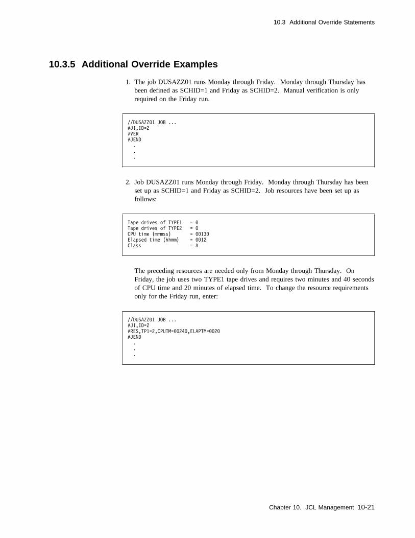
10.3 Additional Override Statements
10.3.5 Additional Override Examples
1. The job DUSAZZ01 runs Monday through Friday. Monday through Thursday hasbeen defined as SCHID=1 and Friday as SCHID=2. Manual verification is onlyrequired on the Friday run.
//DUSAZZ�1 JOB ...
#JI,ID=2
#VER
#JEND
.
.
.
2. Job DUSAZZ01 runs Monday through Friday. Monday through Thursday has beenset up as SCHID=1 and Friday as SCHID=2. Job resources have been set up asfollows:
Tape drives of TYPE1 = �
Tape drives of TYPE2 = �
CPU time (mmmss) = ��13�
Elapsed time (hhmm) = ��12
Class = A
The preceding resources are needed only from Monday through Thursday. OnFriday, the job uses two TYPE1 tape drives and requires two minutes and 40 secondsof CPU time and 20 minutes of elapsed time. To change the resource requirementsonly for the Friday run, enter:
//DUSAZZ�1 JOB ...
#JI,ID=2
#RES,TP1=2,CPUTM=��24�,ELAPTM=��2�
#JEND
.
.
.
Chapter 10. JCL Management 10-21

10.3 Additional Override Statements
3. Assume job XYZ runs daily, Monday through Friday. But on Friday, a control state-ment must be included to indicate a week-ending run and an additional file is to beoutput. Monday through Thursday is defined as SCHID=1 and Friday is defined asSCHID=2. The following sample JCL is for job XYZ:
//XYZ JOB ...
//JOBLIB DD DSN=MY.LOADLIB,DISP=SHR
//STEP1 EXEC PGM=MYPGM
//INPUT DD DSN=INPUT.TRANS,DISP=SHR
//RPTDAILY DD SYSOUT=A
#JI,ID=2
//WKLYOUT DD DSN=WEEK.ENDING.FILE,DISP=(NEW,CATLG)...
#JEND
//SYSIN DD C
#JI,ID=1
DAILY
#JI,ID=2
FRIDAY
#JEND
/C
4. A job has 10 steps. On STEP01 any condition code other than 5 should be consid-ered invalid. If the condition code returned from any step other than STEP01 is notequal to 0, the job should be moved back to the request queue and flagged for restart.
#SCC,COND=(5,NE,STEP�1)
#SCC,COND=(�,NE,C-STEP�1)
5. A job has 5 steps. On STEP01 any condition codes other than 0, 8, 16, and 32should be considered invalid. There is no condition code checking onSTEP02-STEP04. STEP05 should be considered invalid if the condition code is not0 or 54.
Note: The range specified in the first test is 7-1, this is considered equivalent to1-7.
#SCC,COND=(7-1,EQ,STEP�1)
#SCC,COND=(9-15,EQ,STEP�1)
#SCC,COND=(17-31,EQ,STEP�1)
#SCC,COND=(32,LT,STEP�1)
#SCC,COND=(1-53,EQ,STEP�5)
#SCC,COND=(54,LT,STEP�5)
10-22 CA-7 3.3 Database Maintenance Guide
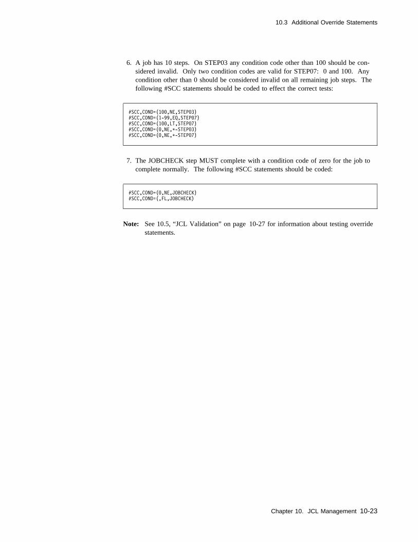
10.3 Additional Override Statements
6. A job has 10 steps. On STEP03 any condition code other than 100 should be con-sidered invalid. Only two condition codes are valid for STEP07: 0 and 100. Anycondition other than 0 should be considered invalid on all remaining job steps. Thefollowing #SCC statements should be coded to effect the correct tests:
#SCC,COND=(1��,NE,STEP�3)
#SCC,COND=(1-99,EQ,STEP�7)
#SCC,COND=(1��,LT,STEP�7)
#SCC,COND=(�,NE,C-STEP�3)
#SCC,COND=(�,NE,C-STEP�7)
7. The JOBCHECK step MUST complete with a condition code of zero for the job tocomplete normally. The following #SCC statements should be coded:
#SCC,COND=(�,NE,JOBCHECK)
#SCC,COND=(,FL,JOBCHECK)
Note: See 10.5, “JCL Validation” on page 10-27 for information about testing overridestatements.
Chapter 10. JCL Management 10-23

10.4 SASSJCLU - JCL Utility
10.4 SASSJCLU - JCL Utility
SASSJCLU is a batch utility program which provides capabilities to:
� Remove expired CA-7 JCL Scheduled Override control statements (#J and #X state-ments) and the scheduled JCL from a JCL library member of a PDS.
� Print the contents of all or selected JCL members in a JCL PDS data set.
Note: This utility can only be applied against a PDS JCL library. Members that areupdated show CA7JCLU as the ID from the last update and ISPF statistics areupdated or created.
The desired function(s) to be performed is indicated through PARM values to theprogram. A SYSIN data set can be used to identify particular members which are to belisted and/or updated.
The utility requires the following execution JCL:
//STEPX EXEC PGM=SASSJCLU,PARM='xxxxxxxx.....x'
//STEPLIB DD DSN=ca7.loadlib,DISP=SHR
//SYSPRINT DD SYSOUT=A
//SYSUT1 DD DSN=JCL-jcl.dataset.name,DISP=OLD
//SYSIN DD C (optional)
control card (optional)
/C
Where:
PARM='xxxxxxxx....x'Acceptable values for PARM='xxxxxxxx....x' may be any of the following:
PRINTPrint the JCL members selected by control statements in the SYSIN data set.
CLEAN=nnRemove all scheduled JCL overrides from JCL members selected for which theending date (ED) is more than nn days prior to today's date.
PANICRemove all scheduled JCL overrides from JCL members selected.
10-24 CA-7 3.3 Database Maintenance Guide
10.4 SASSJCLU - JCL Utility
10.4.1 Usage Notes
Usage considerations for PARM options are:
� If PARM is omitted, PRINT is the default.
� CLEAN=nn causes CA-7 JCL Scheduled Overrides to be removed from the JCLlibrary if their ending date (ED) was more than nn days prior to today's date. IfCLEAN is specified, the 2-digit nn number must be present.
� If CLEAN and PRINT are both specified, expired Scheduled Overrides are removedand the contents of the selected members are listed. If a control statement is presentin the SYSIN data set, only selected members are subject to the CLEAN and PRINToptions in the SYSIN data set.
� If CLEAN is specified and PRINT is not, any JCL member with expired ScheduledOverrides removed is listed anyway.
� PANIC causes all Scheduled Overrides to be removed, expired or not. If a SYSINcontrol statement is specified, only JCL members selected have all Scheduled Over-rides removed.
10.4.1.1 Control Statement
The SYSIN DD statement is required only if a control statement is to be supplied. If theSYSIN statement is not used, all members are selected. The control statement format,starting in position 1 is:
1
NAMEKEY=xxxxxxxx
Where:
xxxxxxxxIs a JCL member name, up to 8 characters, or the first part of a JCL member name(generic selection). Generic selection here does not use an asterisk to indicate theend of the common characters. All JCL members whose first characters match thecharacters specified are subject to the operations specified by the PARM selection.
Note: Care must be taken if member names with fewer than 8 characters are used.For example, if a member name is 4 characters, and they are the same as thefirst 4 characters of an 8-character member name, both are considered.
Only one control statement is allowed per each execution of SASSJCLU.
Chapter 10. JCL Management 10-25
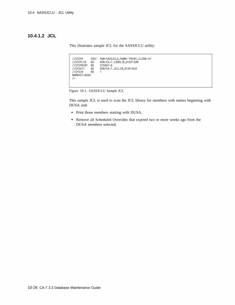
10.4 SASSJCLU - JCL Utility
10.4.1.2 JCL
This illustrates sample JCL for the SASSJCLU utility:
//STEPX EXEC PGM=SASSJCLU,PARM='PRINT,CLEAN=14'
//STEPLIB DD DSN=CA-7.LOADLIB,DISP=SHR
//SYSPRINT DD SYSOUT=A
//SYSUT1 DD DSN=CA-7.JCLLIB,DISP=OLD
//SYSIN DD C
NAMEKEY=DUSA
/C
Figure 10-1. SASSJCLU Sample JCL
This sample JCL is used to scan the JCL library for members with names beginning withDUSA and:
� Print those members starting with DUSA.
� Remove all Scheduled Overrides that expired two or more weeks ago from theDUSA members selected.
10-26 CA-7 3.3 Database Maintenance Guide
10.5 JCL Validation
10.5 JCL Validation
The CA-7 JCL Validation facilities may be invoked from the editor to check for varioussyntax errors. Such validation is available only when the native editor is used in FullEdit Mode (FEM). Thus, if you are using the CA-7 TSO/ISPF Interface, these subcom-mands are not honored in the ISPF editor.
CA-7 relies on CA-JCLCheck to handle JCL validation. A limited set of CA-JCLCheckfunctions is provided as part of the CA-7 base product at no extra cost. However, a moreextensive report of errors is available when using the CA-7 interface with the completeversion of CA-JCLCheck.
Chapter 10. JCL Management 10-27
10.6 LOAD Command Processing
10.6 LOAD Command Processing
Use the LOAD/LOADH command to create or re-create job profile data in the database.Job profiles should agree with the current JCL. Therefore, any changes to the JCL mustbe resynchronized with the database by LOADing the job. See the RELOAD field in2.2.1, “Field Descriptions” on page 2-4 as an alternative to this command. Use theLOADH command to indicate that the job is to be entered into the queue in CA-7 holdstatus to allow for manual release at a future time.
Use of this command causes the rest of the job's JCL to be flushed. The job returns tothe request queue with a JCL error.
You can find more information on the LOAD/LOADH command in the CA-7 CommandsGuide.
10-28 CA-7 3.3 Database Maintenance Guide

10.7 Special Override Library
10.7 Special Override Library
CA-7 supports a JCL override library which is intended to handle any onetime JCL needsthat arise.
The combination of the special override library and the various special override state-ments discussed in 10.2, “Scheduled Overrides” on page 10-6 give the user the ability tohandle virtually every special need that may arise. See that discussion for more detailson the various special functions which are available.
10.7.1 Defining a Special Override Library
Although PDS, CA-Panvalet, and CA-Librarian libraries are supported for execution JCLfor production jobs, this special override library is global for all jobs under the control ofCA-7 and must be a PDS. Only one special override library may be defined to CA-7.
This special override library must be allocated by the user and made available to CA-7through an appropriate DD statement and an initialization file JCL statement which speci-fies INDEX=254. This library is then available to the user on the various screens andcommands as JCL ID of 254.
10.7.2 Creating Temporary JCL
Execution JCL can be placed here, through the DB.7 screen, any time prior to the sched-uling into the queues of the job which uses that JCL. The DB.1 screen fieldUSE-OVRD-LIB must also be set to Y for the special override library JCL to be used. Ifthe DB.7 screen is used to store the JCL in the special override library and the membername is the same as the job name, the USE-OVRD-LIB field is automatically set to Y.
The next time the job is scheduled into the queues, CA-7 uses the special override libraryJCL instead of retrieving the JCL from the primary library specified with the ID field inthe JCL section of the DB.1 screen.
Chapter 10. JCL Management 10-29

10.7 Special Override Library
10.7.3 Using Temporary JCL
When the job is initially brought into the queues and the USE-OVRD-LIB value is Y, theJCL is copied in from the special override library instead of the normal production libraryspecified with the ID field on the DB.1 screen. The USE-OVRD-LIB value is then auto-matically reset to a value of N, to prevent that JCL from being used again.
The JCL that was copied in from the special override library is used until a successfulcompletion of this run is accomplished. It may be altered using the QM.5 screen if nec-essary. When the job completes successfully, the JCL is then deleted from the specialoverride library if the member name DB.1 screen field is the same as the job name.
Note: Your installation may choose to prevent the automatic deletion of JCL from thespecial override library. The OVJCL keyword in the OPTIONS statement in theCA-7 initialization file can be used to prevent this automatic deletion. If thisoption is set, it applies to all CA-7 jobs. See the CA-7 Systems ProgrammerGuide, OPTIONS statement for more information. Before using this option, youshould read 10.8, “Alternate JCL Libraries” on page 10-31 to see if they areappropriate for your situation.
10.7.4 Other Considerations
A LOAD step automatically sets the USE-OVRD-LIB value to N whenever it is executed.If a job has JCL in the special override library waiting for the job to be scheduled and apermanent change is made to the master JCL in the normal production library, any loadof the JCL causes the USE-OVRD-LIB flag to be reset to N. Therefore, such changesmust be avoided, or at least not reloaded with a LOAD top line command, until after thejob has been scheduled into the queues with the set of JCL from the special overridelibrary.
10-30 CA-7 3.3 Database Maintenance Guide

10.8 Alternate JCL Libraries
10.8 Alternate JCL Libraries
CA-7 supports a primary/alternate approach to JCL libraries. This enables the user toplace temporary JCL in a staging-type of library to be used for more than just a singleexecution of a job. The special override library, discussed earlier in this chapter, accom-modates onetime overrides only and the temporary member is deleted after just one exe-cution of the job. CA-7 LOAD processing does not use the alternate JCL library (whenusing the LOAD command).
10.8.1 Defining an Alternate Library
In the initialization file, JCL libraries are defined with a JCL statement. In each of thesestatements, the ALT parameter is used to define which of the defined libraries is to be thealternate library. Only one alternate can be defined for each library.
Libraries may be any of the supported organizations and do not have to be PDS like theglobal special override library.
10.8.2 Creating Temporary JCL
Temporary JCL can be stored in an alternate library from either CA-7 or from outside ofCA-7 (for example, TSO, CA-Roscoe, and so forth). The JCL ID field on the DB.1screen still indicates the JCL resides in the primary library.
10.8.3 Using Temporary JCL
When CA-7 schedules a job which uses a JCL library having an alternate library defined,CA-7 searches the alternate library first. If the JCL member is found in the alternatelibrary, CA-7 uses the alternate JCL and flags the job queue entry. If the JCL member isnot found in the alternate library, CA-7 searches the primary library.
Unlike the special override library previously discussed, no action is taken by CA-7 at jobcompletion to delete JCL used from an alternate library. As long as a JCL member existsin an alternate library, it is used for job scheduling.
The JCL ID specified on the DB.7 screen must specifically request an alternate librarysince the DB.1 screen does not indicate alternate usage. Likewise, the LJCL commandshows JCL only from the primary library.
Runtime messages to the Master Station and the CA-7 comment statement included withthe JCL for the job reflect the JCL ID number for the library from which the JCL wastaken for execution.
Chapter 10. JCL Management 10-31
10.8 Alternate JCL Libraries
10.8.4 Other Considerations
Unlike the onetime Override library (INDEX=254), which is automatically reset by CA-7,the user is responsible for ensuring deletion of temporary JCL from the alternate libraryonce it is no longer needed.
One library can be defined as the alternate for more than one primary library.
An alternate library can have its own alternate. However, searching is only done for theprimary library requested and its single alternate.
10-32 CA-7 3.3 Database Maintenance Guide

Chapter 11. Edit Facility
The CA-7 edit facility is an interactive component used to create, modify and manage80-character, card-image data. With this facility, job streams (JCL) can be created orchanged prior to submittal and documentation (prose) can be maintained in the CA-7database.
This facility consists of files, screens, programs, and a command. The command is EDITwhich can be issued as a top line command or as a screen function. The files are referredto as active area and the edit work file (EWF). The screens and programs vary based onthe environment from which EDIT is issued.
When this facility is invoked, the active area may be cleared or loaded with source data,if requested. The active area is copied to the EWF and an editor program is executed tomake the desired changes. When editing is complete, any saved data is copied back tothe active area from where it can be copied to the source file or some other target file.Figure 11-1 on page 11-2 shows the edit facility data flow.
Chapter 11. Edit Facility 11-1

Figure 11-1. Relationship of Commands, Data Sets, and Screens
11-2 CA-7 3.3 Database Maintenance Guide

11.1 Active Area
11.1 Active Area
The active area is a dynamic file which is suballocated from the scratch queue for eachterminal user. Allocation is performed one track at a time, as needed, to minimize diskspace usage. Maximum allocation is controlled by the SCRTRK or SWFTRK parameteron the DAIO statement in the initialization file. See the CA-7 Systems ProgrammerGuide for more information about these controls.
This file is initialized by the CLEAR and FETCH functions. The CLEAR functionremoves all data from the file and unallocates its disk space. The FETCH function allo-cates disk space and copies data into the file. Several of the DB screens show a fieldcalled ACTIVE SIZE which tells the terminal user how many lines of text are in thisactive area. A CLEAR function is performed at every logon and logoff.
Chapter 11. Edit Facility 11-3
11.2 Edit Work File
11.2 Edit Work File
The edit work file (EWF) is a dynamic file created for each terminal user when EDIT isinvoked. For the CA-7 environment, the file is suballocated from the scratch queue aspreviously described for the active area. For other environments, it is allocated accordingto the rules and conventions of the environment where requested. The EWF space isreleased when leaving the editor.
The EWF is initialized by copying the contents of the active area. An editor program isinvoked in the terminal user's environment to make changes to the EWF data. Whenediting is complete, any saved updates are copied back to the active area and the EWF isfreed.
11-4 CA-7 3.3 Database Maintenance Guide

11.3 Environments
11.3 Environments
Although the editing process is very similar, the editor programs used in each environ-ment are very different. Also, there are considerations unique to each environment whichare in this chapter. Currently, the edit facility supports the following environments:
� CA-7 � TSO/ISPF
Chapter 11. Edit Facility 11-5

11.4 Using the Editor
11.4 Using the Editor
There are three general activities involved in using the editor:
� invoking the editor,� editing text data,� leaving the editor.
When using CA-7, the editor is usually invoked from another command or screen, suchas DB.7 or DB.4, although it can be requested with the EDIT top line command. Whileunder the editor's control, several subcommands are available for editing the text data.After making any desired changes, it is necessary to leave or exit from the editor in orderto retain or make use of the updated text.
11.4.1 Invoking the Editor
The editor is invoked by the top line EDIT command or by using the EDIT or FE (Fetchand Edit) functions from database maintenance or queue maintenance screens or com-mands. Such functions cause the transfer of data from the active area to an edit workfile, as described above, then engage the editor programs for the appropriate environment.
11.4.2 Editing Text Data
Once in the editor, text can be created or changed using the subcommands appropriate tothe environment where editing occurs. Subcommands for the CA-7 environment aredescribed in 11.5, “CA-7 Text Editor Environment” on page 11-8. Subcommands for theTSO/ISPF environment are described in 11.6, “TSO/ISPF Editor Environment” onpage 11-30.
11-6 CA-7 3.3 Database Maintenance Guide
11.4 Using the Editor
11.4.3 Leaving the Editor
After completing the editing tasks desired, the editor must be exited and changes saved, ifdesired. When changes are to be saved, the editor must be told to retain the updates andthe updated EWF data must be transferred back to the active area. If changes are not tobe saved, the editor must be told to release the EWF and not transfer data back to theactive area.
For the CA-7 environment, the subcommands to leave the editor and save the changes areSAVE, SS (SAVE-SAVE), and SR (SAVE-REPLACE). The subcommand to leave theeditor without retaining EWF changes is EXIT. These subcommands are described in11.5, “CA-7 Text Editor Environment” on page 11-8.
For the TSO/ISPF environment, ISPF edit macros are provided which correspond torequired CA-7 editor subcommands. Also, when the editor is invoked, a default subcom-mand is set. If changes are not to be saved, the CA7EXIT subcommand must berequested.
Chapter 11. Edit Facility 11-7
11.5 CA-7 Text Editor Environment
11.5 CA-7 Text Editor Environment
The CA-7 text editor routines provide the capability to create or change text informationin the CA-7 database, queues, and JCL data sets. These routines operate in the CA-7environment servicing multiple terminal users from a single address space and using asingle set of support files (queues). The editor can be invoked using interactive onlinescreens or batch card-image input.
11.5.1 Edit Modes
Earlier versions of CA-7 contained a basic text editor. This editor is still available, but isgenerally used by the batch terminal interface. For online editing, a more flexible editorwas developed that has a more flexible set of routines. Therefore, two versions or modesof the text editor are available. These modes are referred to as Full Edit Mode (FEM)and Alternate Edit Mode (EDIT or AEM). The Full Edit Mode offers more features thanthe Alternate Edit Mode.
When EDIT is entered either as a top line command, from the DB Menu Screen or fromany formatted screen (other than a DB.2.n screen), FEM is automatically invoked (exceptfrom batch). Once in FEM, the RETURN subcommand activates Alternate Edit Mode.To return to Full Edit Mode from Alternate Edit Mode, enter the FEM subcommand.
11.5.1.1 Usage Considerations
� To terminate the text editor modes without retaining changes, enter the EXIT sub-command.
� FEM is not a top line command. It is only used in the text editor facility.
� If the text editor was entered from a top line EDIT command or from a formattedscreen where EDIT is not a listed function (for example, DB.1, DB.6), return is tothe DB Menu screen.
� If the text editor was entered from a formatted screen (other than DB.2.n) whereEDIT is a valid function (for example, DB.7, DB.4), the return is to the originatingscreen.
� Unprintable (or hex) data can cause a 3270 screen error and terminate the usersession.
11-8 CA-7 3.3 Database Maintenance Guide
11.5 CA-7 Text Editor Environment
11.5.1.2 Full Edit Mode (FEM)
Full Edit Mode is entered through the EDIT command, by the FE (Fetch Edit) function,or through the FEM command if already in the Alternate Edit Mode. The FEMcommand can only be entered as a command from the Alternate Edit Mode. FEMreduces the number of operations in editing data. It also allows greater text change flexi-bility.
Normally, when FEM is entered, the edit work file (EWF) is positioned at the top. It ispossible, however, when entering FEM from the Alternate Edit Mode, to specify astarting sequence number. For example, FEM 5725 would place the user in Full EditMode beginning at the line (or next highest) whose sequence number is 5725.
FEM Screen Areas: A Full Edit Mode (FEM) screen consists of six areas ofinformation:
1. Scale Line 2. Status Information 3. Data Area 4. Command Area 5. Message Line 6. Sequence Numbers/Subcommands
For examples of the screens, see “FEM Sample Screens” on page 11-19.
The first area, containing the scale line, appears at the top and bottom of the display.This allows for column-oriented changes in the data area. (An asterisk denotes the lasteffective column.)
The second area contains status information. It appears on the right half of line 2. Itemsof information found here are FILL/NOFILL, MIXED/UPPER case setting, insert incre-ment I (010) and NUM/NONUM.
The third area is the active area. It contains information residing in the edit work file(EWF).
The fourth area on the FEM screen, the command line, appears on the left half of line 2.It is from this line that the commands are input. When the text editor is first entered andthe EWF is empty, lines must be inserted with an INSERTnnn command to enable inputto the EWF.
The fifth area is the message line on the last screen display line. When there is an erroror specific status is required, this line is used. Under normal processing, this line remainsblank.
The sixth area on the FEM screen contains the sequence numbers of the data lines beingdisplayed. This area is used as a subcommand area to delete lines, insert blank lines andposition the display. More than one subcommand can appear in a single sequencenumber.
Chapter 11. Edit Facility 11-9

11.5 CA-7 Text Editor Environment
The following rules apply when the data area, subcommand (sequence number field) andcommand lines are used and the Enter key is pressed:
� When there are no changes to the data area, and no subcommand or command isentered, the display is paged forward (PF) or backward (PB) depending upon thedefault page command showing in the command line.
� When there are changes to the data area, and no subcommand or command isentered, the data changes are applied and the display is positioned according to thedefault page command (PF or PB).
� When subcommands are entered and no command is entered, data area changes aremade, subcommands are processed and the display is positioned at the last P (Posi-tion to this line) subcommand on the screen, or the first line of the current display ifno P subcommand was specified.
� When a command is entered, all subcommands and data area changes are processed.If the command is a display positioning command (TOP, BOTTOM, MD, PF, PB,HF, HB, and so forth), positioning with the subcommand P is ignored. If thecommand is not a display positioning command, the last P subcommand is honored,or the first line of the current display designates the position if no P subcommand isspecified.
FEM Subcommands: The following subcommands can be placed in the sequencenumber area:
PPositions the display to this line. The last P found on the page is honored.
DDeletes the line at this sequence number from the EWF (edit work file).
DDDeletes this line and all subsequent lines to the next DD or end of page.
Note: A DD in the first sequence field of the page when there are no other DDscoded deletes all lines on the current page from the EWF once Enter ispressed.
InnnInserts nnn blank lines after the line where the I appears. nnn must be from 1 to255. Leading zeros are not required. The number of blank lines (nnn) to be insertedmust be truncated by a blank, another subcommand (I, P, D, DD, or R), the EOFkey (erase to End of Field) or the end of the sequence field. These blank linesphysically exist in the EWF and may be altered by making changes in the data areaof subsequent displays. If not truncated, the sequence numbers remaining are consid-ered part of the lines to be inserted.
11-10 CA-7 3.3 Database Maintenance Guide
11.5 CA-7 Text Editor Environment
RnnnRepeats nnn lines after the line where the R appears. The line where the R appearsis repeated. nnn must be from 1 to 255 and must be truncated as in Innn.
Note: Errors in subcommands cause the subcommand to be ignored with no errornotification.
Editor Command Descriptions: The following details the commands availableunder the CA-7 text editor. (The short form of the command is underlined.)
BOTTOMPositions the FEM display to the bottom of the EWF. Available in FEM only.
BREAK [nn]Changes the maximum number of lines to be displayed when the EWF is listed.Value of nn can be from 00 to 99. The default is 99 lines. BREAK with no param-eter establishes the default. Available in FEM and AEM.
CLEARDeletes all lines in the edit work file (EWF). Lines of information added by theEDIT commands, or those already present in the Active Area when the text editorwas entered, are deleted. Available in FEM and AEM.
COL [n,m]Displays only columns n through m for data area changes. The column where theasterisk appears on the scale line is the last affected column. The maximum numberof columns displayed is 72. COL specified with no parameters sets the defaultcolumns of 1 through 72. Available in FEM only.
COPY i[,m,n,t]Duplicates lines m through n and places them after line i, t number of times. Whenn is omitted, line m through the last line are copied t number of times. Two commasmust separate the m and t values when n is omitted. When both m and n areomitted, the last line of the edit work file (EWF) is copied t number of times andthree commas must precede the t. When t is omitted, a default of 1 is assumed.Sequence numbers are assigned to the inserted lines using the current system incre-ment value (see INSERT). The first line copied or moved after the insert line (i) isassigned a sequence number of i plus the current system increment value. All subse-quent inserted lines are renumbered using the system increment value. When manynew lines are inserted, existing lines following the insert point may be renumbered(using the current system increment) to ensure that the EWF remains in sequence.Available in FEM and AEM.
DELETE m[,n]Removes lines from the EWF. When n is omitted, only line m is deleted. When bothm and n are specified, lines m through n are deleted. Available in AEM.
EDITManipulates specified character strings of data, lines of data or columns for reentryinto the EWF. The following EDIT commands are discussed separately. These areonly available in AEM.
Chapter 11. Edit Facility 11-11
11.5 CA-7 Text Editor Environment
EDIT LIST [m,n]Enters Edit List mode. Lines displayed may be changed by keying the changes intothe EWF and pressing Enter. A line displayed on the screen may be deleted bykeying $EDEL in the first 5 characters, or by positioning the cursor at the first char-acter of the line and pressing the EOF key (erase to End-of-Field). Screens arereturned until either the end of the EWF is reached, line n is displayed, or $EEND iskeyed on the last line. ($EEND may be keyed on any line to exit Edit List mode.Any lines displayed from the $EEND to the end of the current Edit List output page,however, are deleted from the EWF.)
EDIT /string/[m,n]Searches the EWF for the string specified. Slash (/) can be any special character andis used as the string delimiter. All lines found from m through n with the specifiedstring of characters are displayed at the terminal. When n is omitted, only line m isscanned. When both m and n are omitted, the entire EWF is scanned. Themaximum number of characters for the string is 54.
EDIT /string1/string2/[m,n]Replaces character string1 with character string2. All occurrences of string1 fromline m through n are replaced by string2. When n is omitted, only line m is scannedfor string1. When both m and n are omitted, the entire EWF is scanned. Themaximum number of characters for string1 and string2 is 54.
EDIT /string//[m,n]Deletes a string of characters. All occurrences of the string from line m through nare deleted. When n is omitted, only line m is scanned for the string. When both mand n are omitted, the entire EWF is scanned. The maximum number of charactersfor the string is 54.
EDIT //string/[m,n]Replaces the contents of the edit columns with the string, regardless of the currentcharacter content. For all lines m through n, the current edit columns are spaced outand the string is left-justified into this area. When n is omitted, only line m ischanged. When both m and n are omitted, the entire EWF is changed. Themaximum number of characters for the string is 54.
EDIT x[,y]Changes the start and end columns to be scanned by the other EDIT commands.When y is omitted, x is the new end column. When x and y are both specified, x isthe new beginning column and y is the new end column. When y is specified, xmust always be less than or equal to y. The values of x and y must be from 1 to 80.
The following are examples of this command:
EDIT 73,80 Changes scan columns to be columns 73through 80.
'E //SASSEDIT/' Fills columns 73 through 80 with SASSEDIT.
E 1,72 Resets scan columns.
11-12 CA-7 3.3 Database Maintenance Guide

11.5 CA-7 Text Editor Environment
EXITReturns to the original function that invoked the text editor. The contents of theactive area are not replaced by the edited EWF. This command is used to exit thetext editor without changing the contents of the active area. See SAVE for changingthe active area contents. Available in FEM and AEM.
FEM [n]Used to enter Full Edit Mode (FEM). n is the sequence of the first line of informa-tion to be positioned in the display. If n is omitted, then the top of the EWF isassumed.
FILLIndicates trailing spaces in the data area of the display are to be preserved. Data areachanges made by positioning to the end of displayed lines are not left-justified to thefirst nonblank character on the line. Available in FEM only.
FIND /xxx...x/[n,m]Searches for a given string of characters (xxx...x) and positions the display at thenext line containing those characters. The slash (/) characters are the string delim-iters and can be any special characters. Searching is always forward from the currentline. To initiate the search from the beginning of the display, first enter the TOPcommand and then the FIND command. FIND always initiates the search for thenext occurrence of the character string. The n and m limits the search to betweenlines n through m of the current command. If m is omitted, only line n is searched ifit follows the top line of the display. If n and m are omitted, the EWF is searchedforward from the current position. The string xxx...x is retained. Subsequent FINDcommands with no operands search forward for the last string of characters specifiedby FIND. Available in FEM only. The following is an example of this command.
HB n]Positions the display n half-pages backward. If omitted, n is assumed to be 1.Available in FEM only.
HF n]Positions the display n half-pages forward. If omitted, n is assumed to be 1. Avail-able in FEM only.
FIND /ABC/0,99999 Searches forward after the first line displayedfor the next line containing ABC. A subsequentFIND positions the display to the next line con-taining ABC. If ABC is not found aftersearching forward, the display is positioned atthe top. A subsequent FIND then searches forABC in any following line. Available in FEMonly.
Chapter 11. Edit Facility 11-13
11.5 CA-7 Text Editor Environment
INSERT [m,i]Used to request Data Insert processing. The operator fills a page with input lines andpresses Enter. The lines are then added to the EWF and a new blank screen withcontinued sequence numbers is presented for more input. To terminate Data Insertprocessing, either key in $IEND after the last line to be inserted, or enter a null lineafter the last line to be inserted.
When both m and i are specified, Data Insert mode processing adds lines beginningwith line m, incremented by i. When i is omitted, m changes the system incrementvalue for the INSERT, MOVE and COPY commands. The default of i is 10. If linem exists in the EWF, Insert mode is established at line m + i (lines are inserted afterline m). Line m is not altered. If both m and i are omitted, Insert mode is estab-lished at the end of the EWF. (In this case, a comma must be used to indicate theabsence of m and i, if sequence numbers are in 73-80.) The first inserted line has asequence number consisting of the last sequence number in the file plus the currentedit increment. The increment value specified here is reflected in the status informa-tion. The INSERT command may be requested in either AEM or FEM. If enteredin FEM, control is passed to the editor in AEM for the duration of Data Insert proc-essing, and is returned to the editor in FEM when processing is complete.
Note: Mixed case support is available only in FEM. Hence, all data added duringData Insert processing will be translated to uppercase.
JCL nnn[,yyddd,hhmm]CA-Driver procedures are expanded, if used. Then CA-7 scans the EWF and reportssyntax errors. The format of the report depends on whether the default or the com-plete version of CA-JCLCheck is used. After the report is displayed, control isreturned to the editor environment where the JCL subcommand was invoked.Default values for schedule ID, date and time are used in CA-Driver procedures andin #JI/#JO statements unless those values are overridden. Use nnn to override thedefault SCHID (1). The default date (current date) may be overridden using yyddd.Use hhmm to override the default time (current time).
JCLL nnn[,yyddd,hhmm]CA-Driver procedures are expanded, if used. Then CA-7 scans the EWF and liststhe JCL statements along with any syntax errors detected. The format of the reportdepends on whether the default or the complete version of CA-JCLCheck is used.After the report is displayed, control is returned to the editor environment where theJCLL subcommand was invoked. Default values for schedule ID, date and time areused in CA-Driver procedures and in #JI/#JO statements unless those values are over-ridden. Use nnn to override the default SCHID (1). The default date (current date)may be overridden using yyddd. Use hhmm to override the default time (currenttime).
11-14 CA-7 3.3 Database Maintenance Guide
11.5 CA-7 Text Editor Environment
JCLS nnn[,yyddd,hhmm]CA-Driver procedures are expanded, if used. Then CA-7 scans the EWF and reportssyntax errors. The format of the report depends on whether the default or the com-plete version of CA-JCLCheck is used. A SAVE subcommand is processed if noerrors are detected and control is returned to the point where the editor was invoked.If errors are detected then after the report is displayed, control will return to theeditor environment where the JCLS subcommand was issued. Default values forschedule ID, date and time are used in CA-Driver procedures and in #JI/#JO state-ments unless those values are overridden. Use nnn to override the default SCHID(1). The default date (current date) may be overridden using yyddd. Use hhmm tooverride the default time (current time).
JCLSR nnn[,yyddd,hhmm]CA-Driver procedures are expanded, if used. Then CA-7 scans the EWF and reportssyntax errors. The format of the report depends on whether the default or the com-plete version of CA-JCLCheck is used. An SR subcommand is processed if noerrors are detected and control is returned to the point where the editor was invoked.If errors are detected then after the report is displayed, control will return to theeditor environment where the JCLSR subcommand was issued. Default values forschedule ID, date and time are used in CA-Driver procedures and in #JI/#JO state-ments unless those values are overridden. Use nnn to override the default SCHID(1). The default date (current date) may be overridden using yyddd. Use hhmm tooverride the default time (current time).
JCLSS nnn[,yyddd,hhmm]CA-Driver procedures are expanded, if used. Then CA-7 scans the EWF and reportssyntax errors. The format of the report depends on whether the default or the com-plete version of CA-JCLCheck is used. An SS subcommand is processed if no errorsare detected and control is returned to the point where the editor was invoked. Iferrors are detected then after the report is displayed, control will return to the editorenvironment where the JCLSS subcommand was issued. Default values for scheduleID, date and time are used in CA-Driver procedures and in #JI/#JO statements unlessthose values are overridden. Use nnn to override the default SCHID (1). The defaultdate (current date) may be overridden using yyddd. Use hhmm to override thedefault time (current time).
LIST [m,n]Displays the contents of the EWF. When n is omitted, only line m is displayed.When both m and n are specified, all lines from m through n are displayed within thelimits of the current BREAK value. When m and n are both omitted, the entire EWFis listed within the limits of the current BREAK value. Available in AEM only.
MD [n]Moves the display to the sequence number specified by n. If n is 0 or omitted, MDis equivalent to the TOP command. If n is 99999, MD is equivalent to theBOTTOM command. Available in FEM only.
Chapter 11. Edit Facility 11-15
11.5 CA-7 Text Editor Environment
MIXEDChanges the current case setting to mixed case. If the current case setting is'MIXED' then characters will not be translated, thus allowing both upper- and lower-case characters to be entered. See the discussion of the UPPER command in thissection for more information on changing the case setting.
The initial case setting is 'UPPER' unless lowercase characters are detected. If lower-case characters are detected and INITCASE=Y is specified on the OPTIONS state-ment in the CA-7 initialization file, the initial case setting is 'MIXED'.
This subcommand is not valid unless INITCASE=Y is specified on the OPTIONSstatement in the CA-7 initialization file. Available in FEM only.
MOVE i[,m,n,t]Places lines m through n after line i, t number of times. When n is omitted, m is theonly line moved. When both m and n are omitted, the last line of the EWF ismoved. When t is omitted, a default of 1 is assumed. Sequence numbers areassigned to the inserted lines using the current system increment value (see INSERT).The first line copied or moved after the insert line i is assigned a sequence number ofi plus the current system increment value. All subsequent inserted lines are renum-bered using the system increment value. When many new lines are inserted, existinglines following the insert point may be renumbered (using the current system incre-ment) to ensure that the EWF remains in sequence. Available in AEM and FEM.
Note: When m or n are omitted, commas must be specified to denote the omissionof these positional parameters.
NOFILLIndicates that trailing spaces in the data area of the display are not preserved. Dataarea changes made by positioning to the end of displayed lines are left-justified to thefirst nonblank character of the line. Spaces must be inserted to hold position. Avail-able in FEM only.
NONUMIndicates that sequence numbers are external to the data. (Same as the XSEQ.)Available in FEM only.
NUMIndicates that sequence numbers are to be found in lines 76 through 80 of the data.(Same as XSEQ OFF.) Available in FEM only.
PB [n]Positions the display n pages backward. If omitted, n is assumed to be 1. Availablein FEM only.
PF [n]Positions the display n pages forward. If omitted, n is assumed to be 1. Available inFEM only.
11-16 CA-7 3.3 Database Maintenance Guide

11.5 CA-7 Text Editor Environment
RENUM m,iRenumbers the entire EWF. Both m and i are required. m is the number to beassigned to the first line of the EWF. i is the increment for each succeeding linenumber. Available in FEM and AEM.
RETURNUsed to enter the Alternate Edit Mode from FEM.
SAVEUsed to return to the original function that invoked the Text Editor. The contents ofthe active area are replaced by the current EWF. This command is used to exit thetext editor with the edited EWF replacing the active area. Available in FEM andAEM.
SCALE [OFF]Indicates whether a column indicator heading is to be displayed on each output page.SCALE OFF turns off Scale mode. SCALE with no operand displays the columnscale. Available in AEM only.
SRPerforms two functions, SAVE and REPL. The current EWF replaces the activearea, control returns to the screen which was used to enter the text editor, and aREPL function is performed. Available in FEM and AEM.
Note: If JCL is being replaced in the Request queue, the SR command also sets anoutstanding JCL override requirement off.
SSPerforms two functions, SAVE and SAVE. The current EWF replaces the activearea, control returns to the screen used to enter the Text Editor, and a SAVE functionis performed. Available in FEM and AEM.
STATUSDisplays current information about the EWF. This information consists of thenumber of lines in the EWF, last line number, edit scan columns, and so on. ThePA1 key must be pressed (page forward) to redisplay the EDIT screen after aSTATUS command. Available in FEM and AEM.
TOPPositions the display to the top of the EWF. Available in FEM only.
Chapter 11. Edit Facility 11-17
11.5 CA-7 Text Editor Environment
TRACE [EDIT] | [OFF]Sets on (TRACE EDIT) or sets off (TRACE OFF) the tracing of lines altered by theeditor commands. With TRACE on, each line changed by the EDIT command isdisplayed. (BREAK does not apply.) Available in FEM and AEM.
UPPERChanges the current case setting to uppercase. If the current case setting is 'UPPER'then all characters will be translated to uppercase.
The initial case setting is 'UPPER' unless lowercase characters are detected. If lower-case characters are detected and INITCASE=Y is specified on the OPTIONS state-ment in the CA-7 initialization file then the initial case setting is 'MIXED'.
XSEQ [OFF]Establishes External Sequence mode. XSEQ alone indicates that the sequencenumbers are to be external to the 1- to 80-character line image. XSEQ OFF indi-cates that columns 76 through 80 of the line image are to be the sequence numberfield. When an active area is saved and XSEQ is in effect, the contents of columns76 through 80 are the same values present when the text editor was entered. WhenXSEQ OFF is in effect and an active area is saved, the current line number for eachline replaces columns 76 through 80 of the line. Available in FEM and AEM.
11-18 CA-7 3.3 Database Maintenance Guide

11.5 CA-7 Text Editor Environment
FEM Sample Screens: The following are FEM sample screens. Each screen displaysthe use of subcommands in the sequence field areas or changes made to the data area.
The following screen shows five of the six areas discussed previously. The last area ofthe screen, the message line, is blank.
FEM Sample Screen 1
� � ----+----1�---+----2�---+----3�---+----4�---+----5�---+----6�---+----7�C
PF NOFILL I(�1�)
���1� //DUSAXX�1 JOB HE67YFSH,ACPAY,REGION=4�K,TIME=���3,CLASS=A
���2� /CROUTE PRINT RMT1
���3� //STEP1 EXEC PGM=IEBGENER
���4� #JI,ID=1
���5� #MSG,CCCCCCCCCCCCCCCCCCCCCCCCCCCCCCCCCCCCCCCCCCCCCCCCCCCCCCCCCCCCCCCCCCC
���6� #MSG,C NETWORK RUN AS SCHID OF 1 C
���7� #MSG,CCCCCCCCCCCCCCCCCCCCCCCCCCCCCCCCCCCCCCCCCCCCCCCCCCCCCCCCCCCCCCCCCCC
���8� #JI,ID=2
���9� #MSG,CCCCCCCCCCCCCCCCCCCCCCCCCCCCCCCCCCCCCCCCCCCCCCCCCCCCCCCCCCCCCCCCCCC
��1�� #MSG,C NETWORK RUN AS SCHID OF 2 C
��11� #MSG,CCCCCCCCCCCCCCCCCCCCCCCCCCCCCCCCCCCCCCCCCCCCCCCCCCCCCCCCCCCCCCCCCCC
��12� #JI,ID=3
��13� #MSG,CCCCCCCCCCCCCCCCCCCCCCCCCCCCCCCCCCCCCCCCCCCCCCCCCCCCCCCCCCCCCCCCCCC
��14� #MSG,C NETWORK RUN AS SCHID OF 3 C
��15� #MSG,CCCCCCCCCCCCCCCCCCCCCCCCCCCCCCCCCCCCCCCCCCCCCCCCCCCCCCCCCCCCCCCCCCC
��16� #JI,ID=4
��17� #MSG,CCCCCCCCCCCCCCCCCCCCCCCCCCCCCCCCCCCCCCCCCCCCCCCCCCCCCCCCCCCCCCCCCCC
��18� #MSG,C NETWORK RUN AS SCHID OF 4 C
��19� #MSG,CCCCCCCCCCCCCCCCCCCCCCCCCCCCCCCCCCCCCCCCCCCCCCCCCCCCCCCCCCCCCCCCCCC
��2�� #JEND
----+----1�---+----2�---+----3�---+----4�---+----5�---+----6�---+----7�C
( )
Chapter 11. Edit Facility 11-19
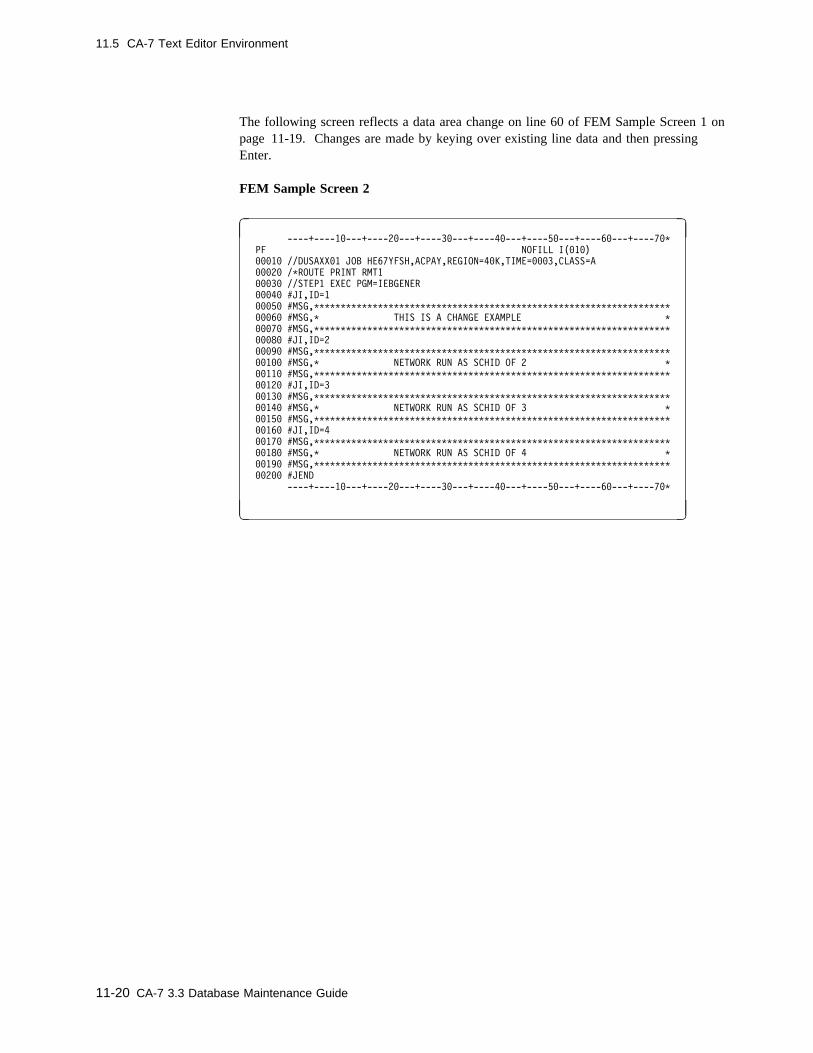
11.5 CA-7 Text Editor Environment
The following screen reflects a data area change on line 60 of FEM Sample Screen 1 onpage 11-19. Changes are made by keying over existing line data and then pressingEnter.
FEM Sample Screen 2
� � ----+----1�---+----2�---+----3�---+----4�---+----5�---+----6�---+----7�C
PF NOFILL I(�1�)
���1� //DUSAXX�1 JOB HE67YFSH,ACPAY,REGION=4�K,TIME=���3,CLASS=A
���2� /CROUTE PRINT RMT1
���3� //STEP1 EXEC PGM=IEBGENER
���4� #JI,ID=1
���5� #MSG,CCCCCCCCCCCCCCCCCCCCCCCCCCCCCCCCCCCCCCCCCCCCCCCCCCCCCCCCCCCCCCCCCCC
���6� #MSG,C THIS IS A CHANGE EXAMPLE C
���7� #MSG,CCCCCCCCCCCCCCCCCCCCCCCCCCCCCCCCCCCCCCCCCCCCCCCCCCCCCCCCCCCCCCCCCCC
���8� #JI,ID=2
���9� #MSG,CCCCCCCCCCCCCCCCCCCCCCCCCCCCCCCCCCCCCCCCCCCCCCCCCCCCCCCCCCCCCCCCCCC
��1�� #MSG,C NETWORK RUN AS SCHID OF 2 C
��11� #MSG,CCCCCCCCCCCCCCCCCCCCCCCCCCCCCCCCCCCCCCCCCCCCCCCCCCCCCCCCCCCCCCCCCCC
��12� #JI,ID=3
��13� #MSG,CCCCCCCCCCCCCCCCCCCCCCCCCCCCCCCCCCCCCCCCCCCCCCCCCCCCCCCCCCCCCCCCCCC
��14� #MSG,C NETWORK RUN AS SCHID OF 3 C
��15� #MSG,CCCCCCCCCCCCCCCCCCCCCCCCCCCCCCCCCCCCCCCCCCCCCCCCCCCCCCCCCCCCCCCCCCC
��16� #JI,ID=4
��17� #MSG,CCCCCCCCCCCCCCCCCCCCCCCCCCCCCCCCCCCCCCCCCCCCCCCCCCCCCCCCCCCCCCCCCCC
��18� #MSG,C NETWORK RUN AS SCHID OF 4 C
��19� #MSG,CCCCCCCCCCCCCCCCCCCCCCCCCCCCCCCCCCCCCCCCCCCCCCCCCCCCCCCCCCCCCCCCCCC
��2�� #JEND
----+----1�---+----2�---+----3�---+----4�---+----5�---+----6�---+----7�C
( )
11-20 CA-7 3.3 Database Maintenance Guide

11.5 CA-7 Text Editor Environment
The following screen reflects the request for deletion of three lines from the EWF. Youmay place a D in any position of the sequence field to delete the line. See FEM SampleScreen 4 on page 11-22 for the results of this edit.
FEM Sample Screen 3
� � ----+----1�---+----2�---+----3�---+----4�---+----5�---+----6�---+----7�C
PF NOFILL I(�1�)
���1� //DUSAXX�1 JOB HE67YFSH,ACPAY,REGION=4�K,TIME=���3,CLASS=A
���2� /CROUTE PRINT RMT1
���3� //STEP1 EXEC PGM=IEBGENER
���4� #JI,ID=1
���5� #MSG,CCCCCCCCCCCCCCCCCCCCCCCCCCCCCCCCCCCCCCCCCCCCCCCCCCCCCCCCCCCCCCCCCCC
���6� #MSG,C THIS IS A CHANGE EXAMPLE C
���7� #MSG,CCCCCCCCCCCCCCCCCCCCCCCCCCCCCCCCCCCCCCCCCCCCCCCCCCCCCCCCCCCCCCCCCCC
D��8� #JI,ID=2 ���9� #MSG,CCCCCCCCCCCCCCCCCCCCCCCCCCCCCCCCCCCCCCCCCCCCCCCCCCCCCCCCCCCCCCCCCCC
��1�� #MSG,C NETWORK RUN AS SCHID OF 2 C
��11� #MSG,CCCCCCCCCCCCCCCCCCCCCCCCCCCCCCCCCCCCCCCCCCCCCCCCCCCCCCCCCCCCCCCCCCC
��12D #JI,ID=3
��13� #MSG,CCCCCCCCCCCCCCCCCCCCCCCCCCCCCCCCCCCCCCCCCCCCCCCCCCCCCCCCCCCCCCCCCCC
��14� #MSG,C NETWORK RUN AS SCHID OF 3 C
��15� #MSG,CCCCCCCCCCCCCCCCCCCCCCCCCCCCCCCCCCCCCCCCCCCCCCCCCCCCCCCCCCCCCCCCCCC
��D6� #JI,ID=4 ��17� #MSG,CCCCCCCCCCCCCCCCCCCCCCCCCCCCCCCCCCCCCCCCCCCCCCCCCCCCCCCCCCCCCCCCCCC
��18� #MSG,C NETWORK RUN AS SCHID OF 4 C
��19� #MSG,CCCCCCCCCCCCCCCCCCCCCCCCCCCCCCCCCCCCCCCCCCCCCCCCCCCCCCCCCCCCCCCCCCC
��2�� #JEND
----+----1�---+----2�---+----3�---+----4�---+----5�---+----6�---+----7�C
( )
Chapter 11. Edit Facility 11-21

11.5 CA-7 Text Editor Environment
The following screen reflects the results of the edit performed in FEM Sample Screen 3on page 11-21 deleting three lines: 00080, 00120, and 00160.
Now a P is placed in the sequence field on line 100. See FEM Sample Screen 5 onpage 11-23 for the results.
FEM Sample Screen 4
� � ----+----1�---+----2�---+----3�---+----4�---+----5�---+----6�---+----7�C
PF NOFILL I(�1�)
���1� //DUSAXX�1 JOB HE67YFSH,ACPAY,REGION=4�K,TIME=���3,CLASS=A
���2� /CROUTE PRINT RMT1
���3� //STEP1 EXEC PGM=IEBGENER
���4� #JI,ID=1
���5� #MSG,CCCCCCCCCCCCCCCCCCCCCCCCCCCCCCCCCCCCCCCCCCCCCCCCCCCCCCCCCCCCCCCCCCC
���6� #MSG,C THIS IS A CHANGE EXAMPLE C
���7� #MSG,CCCCCCCCCCCCCCCCCCCCCCCCCCCCCCCCCCCCCCCCCCCCCCCCCCCCCCCCCCCCCCCCCCC
���9� #MSG,CCCCCCCCCCCCCCCCCCCCCCCCCCCCCCCCCCCCCCCCCCCCCCCCCCCCCCCCCCCCCCCCCCC
P�1�� #MSG,C NETWORK RUN AS SCHID OF 2
��11� #MSG,CCCCCCCCCCCCCCCCCCCCCCCCCCCCCCCCCCCCCCCCCCCCCCCCCCCCCCCCCCCCCCCCCCC
��13� #MSG,CCCCCCCCCCCCCCCCCCCCCCCCCCCCCCCCCCCCCCCCCCCCCCCCCCCCCCCCCCCCCCCCCCC
��14� #MSG,C NETWORK RUN AS SCHID OF 3 C
��15� #MSG,CCCCCCCCCCCCCCCCCCCCCCCCCCCCCCCCCCCCCCCCCCCCCCCCCCCCCCCCCCCCCCCCCCC
��17� #MSG,CCCCCCCCCCCCCCCCCCCCCCCCCCCCCCCCCCCCCCCCCCCCCCCCCCCCCCCCCCCCCCCCCCC
��18� #MSG,C NETWORK RUN AS SCHID OF 4 C
��19� #MSG,CCCCCCCCCCCCCCCCCCCCCCCCCCCCCCCCCCCCCCCCCCCCCCCCCCCCCCCCCCCCCCCCCCC
��2�� #JEND
----+----1�---+----2�---+----3�---+----4�---+----5�---+----6�---+----7�C
( )
11-22 CA-7 3.3 Database Maintenance Guide

11.5 CA-7 Text Editor Environment
The following screen reflects the result of the P subcommand to position the display fromFEM Sample Screen 4 on page 11-22 to line 100.
Now an I3 is placed in sequence line 200. See FEM Sample Screen 6 on page 11-24 forthe results.
FEM Sample Screen 5
� � ----+----1�---+----2�---+----3�---+----4�---+----5�---+----6�---+----7�C
PF NOFILL I(�1�)
��1�� #MSG,C NETWORK RUN AS SCHID OF 2 C
��11� #MSG,CCCCCCCCCCCCCCCCCCCCCCCCCCCCCCCCCCCCCCCCCCCCCCCCCCCCCCCCCCCCCCCCCCC
��13� #MSG,CCCCCCCCCCCCCCCCCCCCCCCCCCCCCCCCCCCCCCCCCCCCCCCCCCCCCCCCCCCCCCCCCCC
��14� #MSG,C NETWORK RUN AS SCHID OF 3 C
��15� #MSG,CCCCCCCCCCCCCCCCCCCCCCCCCCCCCCCCCCCCCCCCCCCCCCCCCCCCCCCCCCCCCCCCCCC
��17� #MSG,CCCCCCCCCCCCCCCCCCCCCCCCCCCCCCCCCCCCCCCCCCCCCCCCCCCCCCCCCCCCCCCCCCC
��18� #MSG,C NETWORK RUN AS SCHID OF 4 C
��19� #MSG,CCCCCCCCCCCCCCCCCCCCCCCCCCCCCCCCCCCCCCCCCCCCCCCCCCCCCCCCCCCCCCCCCCC
I3 �� #JEND ��21� //SYSIN DD DUMMY
��22� //SYSPRINT DD SYSOUT=A
��23� //SYSUT2 DD DSN=CA-7.TEST1,
��24� // DISP=(NEW,CATLG,DELETE),UNIT=DISKA,VOL=SER=LIB112,SPACE=(TRK,1),
��25� // DCB=(RECFM=F,LRECL=8�,BLKSIZE=8�)
��26� //SYSUT1 DD C,DCB=BLKSIZE=8�
��27� /C
��28� //STEP2 EXEC PGM=SASSTRLR,PARM=ACT
��29� //STEPLIB DD DSN=CA-7.LOADLIB,DISP=SHR
��3�� //SYSPRINT DD SYSOUT=A
��31� //SYSOUT DD SYSOUT=A,DCB=BLKSIZE=133
----+----1�---+----2�---+----3�---+----4�---+----5�---+----6�---+----7�C
( )
Chapter 11. Edit Facility 11-23

11.5 CA-7 Text Editor Environment
The following screen reflects the result of the I subcommand to insert three blank linesafter line 200. An I3 (I3space) was entered in the sequence field of line 200. Theinserted lines were incremented by 10, the line increment value on the status line. Theprevious line 210 has been renumbered to 240. All subsequent lines are renumbered asnecessary to retain ascending sequence numbers in the EWF.
Now a DD is placed in sequence lines 150 and 200. See FEM Sample Screen 7 onpage 11-25 for the results.
FEM Sample Screen 6
� � ----+----1�---+----2�---+----3�---+----4�---+----5�---+----6�---+----7�C
PF NOFILL I(�1�)
��1�� #MSG,C NETWORK RUN AS SCHID OF 2 C
��11� #MSG,CCCCCCCCCCCCCCCCCCCCCCCCCCCCCCCCCCCCCCCCCCCCCCCCCCCCCCCCCCCCCCCCCCC
��13� #MSG,CCCCCCCCCCCCCCCCCCCCCCCCCCCCCCCCCCCCCCCCCCCCCCCCCCCCCCCCCCCCCCCCCCC
��14� #MSG,C NETWORK RUN AS SCHID OF 3 C
DD15� #MSG,CCCCCCCCCCCCCCCCCCCCCCCCCCCCCCCCCCCCCCCCCCCCCCCCCCCCCCCCCCC ��17� #MSG,CCCCCCCCCCCCCCCCCCCCCCCCCCCCCCCCCCCCCCCCCCCCCCCCCCCCCCCCCCCCCCCCCCC
��18� #MSG,C NETWORK RUN AS SCHID OF 4 C
��19� #MSG,CCCCCCCCCCCCCCCCCCCCCCCCCCCCCCCCCCCCCCCCCCCCCCCCCCCCCCCCCCCCCCCCCCC
DD2�� #JEND ��21�
��22�
��23�
��24� //SYSIN DD DUMMY
��25� //SYSPRINT DD SYSOUT=A
��26� //SYSUT2 DD DSN=CA-7.TEST1,
��27� // DISP=(NEW,CATLG,DELETE),UNIT=DISKA,VOL=SER=LIB112,SPACE=(TRK,1),
��28� // DCB=(RECFM=F,LRECL=8�,BLKSIZE=8�)
��29� //SYSUT1 DD C,DCB=BLKSIZE=8�
��3�� /C
��31� //STEP2 EXEC PGM=SASSTRLR,PARM=ACT
----+----1�---+----2�---+----3�---+----4�---+----5�---+----6�---+----7�C
( )
11-24 CA-7 3.3 Database Maintenance Guide

11.5 CA-7 Text Editor Environment
The following screen reflects the result of the DD subcommand to delete multiple linesfrom the EWF. A DD was placed in the sequence field of lines 150 and 200 of FEMSample Screen 6 on page 11-24. Lines 150 through 200 are deleted from the EWF.
FEM Sample Screen 7
� � ----+----1�---+----2�---+----3�---+----4�---+----5�---+----6�---+----7�C
PF NOFILL I(�1�)
��1�� #MSG,C NETWORK RUN AS SCHID OF 2 C
��11� #MSG,CCCCCCCCCCCCCCCCCCCCCCCCCCCCCCCCCCCCCCCCCCCCCCCCCCCCCCCCCCCCCCCCCCC
��13� #MSG,CCCCCCCCCCCCCCCCCCCCCCCCCCCCCCCCCCCCCCCCCCCCCCCCCCCCCCCCCCCCCCCCCCC
��14� #MSG,C NETWORK RUN AS SCHID OF 3 C
��21�
��22�
��23�
��24� //SYSIN DD DUMMY
��25� //SYSPRINT DD SYSOUT=A
��26� //SYSUT2 DD DSN=CA-7.TEST1,
��27� // DISP=(NEW,CATLG,DELETE),UNIT=DISKA,VOL=SER=LIB112,SPACE=(TRK,1),
��28� // DCB=(RECFM=F,LRECL=8�,BLKSIZE=8�)
��29� //SYSUT1 DD C,DCB=BLKSIZE=8�
��3�� /C
��31� //STEP2 EXEC PGM=SASSTRLR,PARM=ACT
��32� //STEPLIB DD DSN=CA-7.LOADLIB,DISP=SHR
��33� //SYSPRINT DD SYSOUT=A
��34� //SYSOUT DD SYSOUT=A,DCB=BLKSIZE=133
��35� //SYSIN DD C,DCB=BLKSIZE=8�
��36� /LOGON MASTER
----+----1�---+----2�---+----3�---+----4�---+----5�---+----6�---+----7�C
( )
The following screen reflects multiple subcommands entered on the screen.
FEM Sample Screen 8
� � ----+----1�---+----2�---+----3�---+----4�---+----5�---+----6�---+----7�C
PF NOFILL I(�1�)
��1�� #MSG,C NETWORK RUN AS SCHID OF 2 C
��11� #MSG,CCCCCCCCCCCCCCCCCCCCCCCCCCCCCCCCCCCCCCCCCCCCCCCCCCCCCCCCCCCCCCCCCCC
��13� #MSG,CCCCCCCCCCCCCCCCCCCCCCCCCCCCCCCCCCCCCCCCCCCCCCCCCCCCCCCCCCCCCCCCCCC
��14� #MSG,C NETWORK RUN AS SCHID OF 3 C
��21�
��22�
��23�
��24� //SYSIN DD DUMMY
��25� //SYSPRINT DD SYSOUT=A
P�26� //SYSUT2 DD DSN=CA-7.TEST1, ��27� // DISP=(NEW,CATLG,DELETE),UNIT=DISKA,VOL=SER=LIB112,SPACE=(TRK,1),
��28� // DCB=(RECFM=F,LRECL=8�,BLKSIZE=8�)
D�29� //SYSUT1 DD C,DCB=BLKSIZE=8� ��3�� /C
DD31� //STEP2 EXEC PGM=SASSTRLR,PARM=ACT ��32� //STEPLIB DD DSN=CA-7.LOADLIB,DISP=SHR
DD33� //SYSPRINT DD SYSOUT=A ��34� //SYSOUT DD SYSOUT=A,DCB=BLKSIZE=133
I2 5� //SYSIN DD C,DCB=BLKSIZE=8� ��36� /LOGON MASTER
----+----1�---+----2�---+----3�---+----4�---+----5�---+----6�---+----7�C
( )
Chapter 11. Edit Facility 11-25
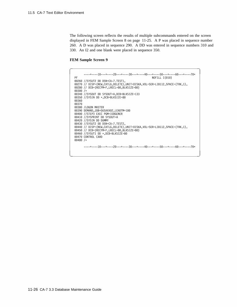
11.5 CA-7 Text Editor Environment
The following screen reflects the results of multiple subcommands entered on the screendisplayed in FEM Sample Screen 8 on page 11-25. A P was placed in sequence number260. A D was placed in sequence 290. A DD was entered in sequence numbers 310 and330. An I2 and one blank were placed in sequence 350.
FEM Sample Screen 9
� � ----+----1�---+----2�---+----3�---+----4�---+----5�---+----6�---+----7�C
PF NOFILL I(�1�)
��26� //SYSUT2 DD DSN=CA-7.TEST1,
��27� // DISP=(NEW,CATLG,DELETE),UNIT=DISKA,VOL=SER=LIB112,SPACE=(TRK,1),
��28� // DCB=(RECFM=F,LRECL=8�,BLKSIZE=8�)
��3�� /C
��34� //SYSOUT DD SYSOUT=A,DCB=BLKSIZE=133
��35� //SYSIN DD C,DCB=BLKSIZE=8�
��36�
��37�
��38� /LOGON MASTER
��39� DEMAND,JOB=DUSAXX�2,LEADTM=1��
��4�� //STEP3 EXEC PGM=IEBGENER
��41� //SYSPRINT DD SYSOUT=A
��42� //SYSIN DD DUMMY
��43� //SYSUT2 DD DSN=CA-7.TEST2,
��44� // DISP=(NEW,CATLG,DELETE),UNIT=DISKA,VOL=SER=LIB112,SPACE=(TRK,1),
��45� // DCB=(RECFM=F,LRECL=8�,BLKSIZE=8�)
��46� //SYSUT1 DD C,DCB=BLKSIZE=8�
��47� CONTROL CARD
��48� /C
----+----1�---+----2�---+----3�---+----4�---+----5�---+----6�---+----7�C
( )
11-26 CA-7 3.3 Database Maintenance Guide
11.5 CA-7 Text Editor Environment
11.5.2 Updating Text
The most common editing activity is to make changes to existing text. The following is astep-by-step example for this activity using the CA-7 text editor. In the example, theprimary screen is the DB.7 screen, but the same steps apply to other screens, such asDB.4 and QM.5.
See Figure 11-1 on page 11-2.
To update text proceed as follows:
1. Display the primary screen, in this case, DB.7.
2. Type FE in the function field, then enter the required fields to identify the source ofthe text to be edited, such as MEMBER and DSN or JCL-ID, and press Enter.
3. Use the editor subcommands to make desired changes to the text.
4. Enter the SAVE or SR subcommand to retain the changes and return to the DB.7screen. If SAVE is used to leave the editor, another function is required on the DB.7screen to move the updated text to a permanent file. IF SR is used to leave theeditor, the source file identified in step 2 is updated. If the text updates are not to besaved, leave the editor using the EXIT subcommand.
Chapter 11. Edit Facility 11-27

11.5 CA-7 Text Editor Environment
11.5.3 Creating Text
Another common editing activity is to create text from scratch. The following is a step-by-step example for this activity using the CA-7 text editor. In the example, the primaryscreen is the DB.4 screen, but the same steps apply to other screens, such as DB.7 andQM.5.
See Figure 11-1 on page 11-2.
To create text, proceed as follows:
1. Display the primary screen, in this case, DB.4.
2. Since this is a menu screen, a secondary entry is required, such as 1 for job leveldocumentation.
3. Once on the DB.4.1 screen, enter CLEAR in the function field to initialize the activearea. (If the active size is 0, this step can be bypassed.)
4. Next enter EDIT in the function field to transfer to the editor. The edit screenreturned indicates EWF EMPTY.
5. Enter I or INSERT which to invoke Data Insert processing.
6. Enter text as desired. Lines are double spaced with sequence numbers protected. Iftext is entered on all numbered lines displayed, another screen of blank lines is pre-sented for continued entry. After all input is complete, leave at least one blank lineon the screen and press Enter to return to FEM.
7. If changes are needed to the newly created text, use the editor subcommands tomanipulate the data.
8. Enter the SAVE subcommand to retain the text and return to the DB.4.1 screen.
9. Type SAVE in the function field and the job name in the JOB field. Data may beentered in the other fields as well. Press Enter to add the text to the database. (If nodata is to be entered in the other fields, SS can be done in Step 8 which does steps 8and 9 with one command.)
11-28 CA-7 3.3 Database Maintenance Guide

11.5 CA-7 Text Editor Environment
11.5.4 Special Considerations
11.5.4.1 PF/PA Key Usage
While in the CA-7 text editor, PF and PA keys should not be used. These keys may beequated to top line commands not valid in the editor, and their use can cause unpredict-able results. Even if the equated command works, all edit data is lost since the EWF isnot saved to the Active Area.
11.5.4.2 Character Translation
CA-7 translates all character data to uppercase unless the text editor is used in Full EditMode. If using FEM, then character data will be translated or not depending on the casesetting. If the case setting is 'UPPER', then all character data will be translated to upper-case. If the case setting is 'MIXED' then characters on data lines will be left untranslated.The FEM subcommands MIXED and UPPER may be used to change the case setting.The current case setting is reported on the status line.
On entry to the CA-7 editor in Full Edit Mode the case setting is 'UPPER' unless lower-case characters are detected. In that event the initial case setting is 'MIXED'.
If the case setting is changed to 'UPPER' then all character data in the editor will betranslated to uppercase when it is saved to the active area. If data is not saved then thecase setting only affects the current data display.
The case setting may not be changed unless INITCASE=Y is specified on the OPTIONSstatement in the CA-7 Initialization File. If this value is not specified then the casesetting is always set to 'UPPER' and cannot be changed.
When data is stored in the database or queue files, it is compressed using control codesfor repeated characters.
11.5.4.3 Nondisplayable Data (hex)
Nondisplayable data contained in text edited using the CA-7 text editor can cause unpre-dictable screen output or a terminal disconnect. Avoid editing files containing such data.
Chapter 11. Edit Facility 11-29
11.6 TSO/ISPF Editor Environment
11.6 TSO/ISPF Editor Environment
The CA-7 TSO/ISPF Interface allows for the fully integrated use of the ISPF editorwhere text editing is required. Some of the features described in 11.5, “CA-7 Text EditorEnvironment” on page 11-8 are available in the ISPF environment as well. There arehowever, important differences, and these are noted in this subtopic.
This subtopic explains the use of the ISPF editor only as supported under the CA-7TSO/ISPF Interface.
In the following discussion, two types of CA-7 online terminal sessions are compared andcontrasted:
� a directly connected CA-7 terminal session� an ISPF connected CA-7 terminal session
A CA-7 online terminal session that is acquired outside of ISPF is considered directlyconnected. A CA-7 terminal session acquired from an ISPF session is considered anISPF connected session.
Regardless of how the terminal session is connected, the file that is edited in CA-7 isalways an EWF or Editor Work File. The format of the EWF differs depending on thetype of terminal session where the editing occurs.
When editing takes place in a directly connected session (in a session where theTSO/ISPF interface is not being used), the EWF is a file internal to CA-7. Manipulationof data on the file is handled entirely by CA-7 in the CA-7 address space in response toCA-7 editor commands entered by the user.
In an ISPF connected session (in a CA-7 terminal session acquired under ISPF), the EWFis a temporary data set that is dynamically allocated and maintained by programs runningunder the ISPF session. All data manipulation takes place in the TSO user's addressspace using the ISPF editor.
In the TSO user's address space, the ISPF editor is used strictly for data manipulation.The primary source or target file (for example, a JCL library) is never updated by theISPF session. All updates are handled by CA-7 from the CA-7 address space. The pre-vious discussion detailing the flow of data between primary source/target, active area andEWF is valid not only for editing from a directly connected session but also from anISPF connected session.
11-30 CA-7 3.3 Database Maintenance Guide

11.6 TSO/ISPF Editor Environment
11.6.1 Requesting CA-7 Edit Functions from the ISPF Editor
There are several CA-7 functions which may be requested from the editor screens whichcause termination of the edit session. These functions differ in the data movement thattakes place when the function is requested. In a directly connected CA-7 terminalsession, the subcommands used to request these functions are:
SAVE Terminates the edit session and saves the contents of the EWF to the activearea.
EXIT Terminates the edit session without saving the contents of the EWF.
SS Terminates the edit session, saves the contents of the EWF in the active area,and saves the contents of the active area to the primary source.
SR Terminates the edit session, saves the contents of the EWF in the active area,and replaces the primary source with the contents of the active area.
SS and SR processing differs from the descriptions offered above if queue JCL is beingedited.
All primary source/target updates are handled by CA-7; therefore, some means must beprovided to allow the user to indicate to the interface programs from the editor, whatCA-7 is to do with the data in the EWF when the edit session is terminated. In an ISPFconnected CA-7 terminal session, the following ISPF edit macros may be used to requestthe CA-7 edit functions described above:
CA7SAVE Terminates the edit session. Sends EWF to CA-7 and requests SAVEprocessing. Deletes the temporary data set (EWF).
CA7EXIT Terminates the edit session. Sends EXIT request to CA-7. Deletes thetemporary data set (EWF).
CA7SS Terminates the edit session. Sends EWF to CA-7 and requests SS proc-essing. Deletes the temporary data set (EWF).
CA7SR Terminates the edit session. Sends EWF to CA-7 and requests SR proc-essing. Deletes the temporary data set (EWF).
These are standard ISPF edit macros, provided as CLISTs. When one of these CLISTs isinvoked, the value of an internal variable is set. The interface programs retrieve thevalue of the variable and request the appropriate CA-7 edit function (for example, SAVE,SS, SR, or EXIT).
Chapter 11. Edit Facility 11-31
11.6 TSO/ISPF Editor Environment
11.6.2 Default Requests for CA-7 Edit Functions
In an ISPF connected CA-7 terminal session, a CA-7 editor function is always requestedwhen the editor is exited. This function may be requested either explicitly, as in the caseof one of the edit macros, or may be requested by default if the editor is exited in anyother way (if, for example, PF03 is set to END and PF03 is pressed).
The CA-7 edit action that is requested by default is named in a message that appearswhen the editor is entered.
IF DATA IS SAVED, THEN A CA-7 xxxx WILL BE PERFORMED
Where:
xxxx may be either EXIT, SAVE, SS, or SR. The default action is set to SR initially.The default setting may be changed for subsequent edit sessions by issuing an edit macro.For example, if the default that appears in the message is SR, and if the CA7SS editmacro is used to terminate an edit session, then on the next session, the default settingthat appears in the message is SS. This is the action that CA-7 performs if the editsession is terminated and data is saved. If data is not saved, CA7EXIT is requested bydefault. For example, suppose that the following message appears when the editor isentered for a member on a JCL library:
IF DATA IS SAVED, THEN A CA-7 SR WILL BE PERFORMED
Also suppose that an ISPF SAVE command is issued during the edit session. If the editsession is terminated without issuing a CA-7 edit macro then a CA-7 SR is requested. Inthis case, if the user did not want the data to replace the JCL member, a CA7EXIT wouldbe required. An ISPF CANCEL would not suffice to prevent the SR from being issued,because an ISPF SAVE command was entered. The only way to avoid an implicitrequest for the default action is to enter the appropriate CA-7 edit macro. AUTOSAVEON is a common edit profile setting and in many cases data may be saved automaticallyif data is changed. It is very important to be aware of the default CA-7 edit function thatmay be issued when leaving the edit session.
11-32 CA-7 3.3 Database Maintenance Guide

11.6 TSO/ISPF Editor Environment
In the following example, text for an existing member of a JCL PDS is updated.
1. Request the JCL screen by typing DB.7 on the top line.
2. Enter FE in the field marked FUNCTION. Enter the member name in the fieldmarked MEMBER. Enter all other information necessary to locate the member(JCLID or DSN and so forth), then press Enter.
3. The ISPF editor is invoked and data from the active area appears. Use ISPF editorcommands to make desired changes.
4. Enter CA7SR from the command line to save the changes. To exit the editor withoutsaving any changes, enter CA7EXIT from the command line. If the default CA-7edit function is acceptable and if data was changed and if AUTOSAVE ON is set inthe edit profile, then simply exit the editor using the ISPF END command (through aPF KEY if desired).
Chapter 11. Edit Facility 11-33

11.6 TSO/ISPF Editor Environment
11.6.3 Special Considerations
11.6.3.1 ISPF Edit Profile Settings
In an ISPF connected CA-7 terminal session, the EWF is a temporary data set that isacquired only when needed by the interface programs and is deleted when the user exitsthe editor. It is a temporary data set and it is not retained in the event of abnormaltermination, thus the recovery mode setting in the ISPF edit profile is of little benefit.
Although the ISPF editor command to set CAPS OFF is valid in an ISPF connectedsession, such a setting is effectively ignored since CA-7 is handling all output to theprimary source/target. When the EWF is received, CA-7 translates all lowercase charac-ters to uppercase prior to update of the active area.
Note: Edit facilities are restricted to character data whether the terminal session isdirectly connected or ISPF connected. Even though in an ISPF connected sessionHEX ON may be used to create unprintable hex data, this is strongly discouragedsince CA-7's response to such data is unpredictable.
11.6.3.2 PF/PA Key Usage
Although both CA-7 and ISPF allow command input through a PF key, in the ISPF editorall PF keys are used for ISPF command input only. See the CA-7 Systems ProgrammerGuide for further information on PF keys in an ISPF connected CA-7 terminal session.
The use of PA keys is strictly subject to ISPF restrictions. PA key interrupts are notsupported in an ISPF connected terminal session.
11.6.3.3 SUBMIT Function
If JCL is submitted using the ISPF SUBMIT function, CA-7 does not track the job. It isrecommended that the SUBMIT function be deactivated through an ISPF command tablefor the CA7 application. See the CA-7 Systems Programmer Guide for further informa-tion on command table modifications for the CA7 application.
11.6.3.4 Size of Data
The maximum number of lines (or records) that can be edited using the ISPF interface isapproximately 5000.
11-34 CA-7 3.3 Database Maintenance Guide

Chapter 12. Database Verification
Database verification consists of two basic database facilities, pointer verification andanalyze commands. Pointer verification is used to verify contents of the database andexecutes in batch mode outside of CA-7. Analyze Commands are used to list, andoptionally update, database contents from CA-7 terminals.
Chapter 12. Database Verification 12-1

12.1 Pointer Verification
12.1 Pointer Verification
Module UCC7DBVR can be used to verify logical pointers in the database. When indi-cated by keywords from the control statements or PARM input, UCC7DBVR reads thedatabase and checks pointers by record type.
12.1.1 Pointer Verification Parameters
The PARM or DBVPARM DD statement parameters available to request pointer verifica-tion are as follows:
IDSVERFYVerifies logical pointers for data sets, networks, and documentation members to thedatabase Index Data Set (IDS) entries.
NWSCHDVerifies that a one-to-one relationship exists between CA-7 networks having sched-ules and the schedules themselves.
JOBSCHDVerifies that a one-to-one relationship exists between jobs having schedules and theschedules themselves.
ALLVSAMIndicates the organization used for the CA-7 database. ALLVSAM indicates thedatabase is totally VSAM as defined in the control statements residing in theDBPARMS data set. See the CA-7 Systems Programmer Guide for details on thecontents of the DBPARMS data set. The same values used in the UCC7DBASEstatements when the database was last loaded must be used here also to ensurecorrect access to the ALLVSAM database.
The parameters must appear in the execution JCL in either of the following formats:
PARM='ALLVSAM[,IDSVERFY][,NWSCHD][,JOBSCHD]'
-or-
//DBVPARM DD C
ALLVSAM [,IDSVERFY][,NWSCHD][,JOBSCHD]
When using the DBVPARM DD, the parameters must start in column 1.
12-2 CA-7 3.3 Database Maintenance Guide
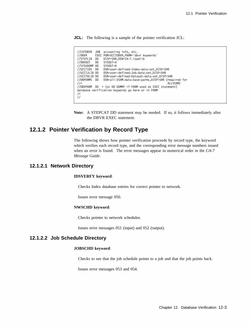
12.1 Pointer Verification
JCL: The following is a sample of the pointer verification JCL:
//CA7DBVR JOB accounting info, etc.
//DBVR EXEC PGM=UCC7DBVR,PARM='dbvr keywords'
//STEPLIB DD DISP=SHR,DSN=CA-7.loadlib
//DBVOUT DD SYSOUT=A
//SYSUDUMP DD SYSOUT=A
//UCC7IDS DD DSN=user-defined-Index-data-set,DISP=SHR
//UCC7JLIB DD DSN=user-defined-Job-data-set,DISP=SHR
//UCC7DLIB DD DSN=user-defined-Dataset-data-set,DISP=SHR
//DBPARMS DD DSN=all-VSAM-data-base-parms,DISP=SHR (required for
//C ALLVSAM)
//DBVPARM DD C (or DD DUMMY if PARM used on EXEC statement)
database verification keywords go here or in PARM
/C
//
Note: A STEPCAT DD statement may be needed. If so, it follows immediately afterthe DBVR EXEC statement.
12.1.2 Pointer Verification by Record Type
The following shows how pointer verification proceeds by record type, the keywordwhich verifies each record type, and the corresponding error message numbers issuedwhen an error is found. The error messages appear in numerical order in the CA-7Message Guide.
12.1.2.1 Network Directory
IDSVERFY keyword:
Checks Index database entries for correct pointer to network.
Issues error message 050.
NWSCHD keyword:
Checks pointer to network schedules.
Issues error messages 051 (input) and 052 (output).
12.1.2.2 Job Schedule Directory
JOBSCHD keyword:
Checks to see that the job schedule points to a job and that the job points back.
Issues error messages 053 and 054.
Chapter 12. Database Verification 12-3

12.1 Pointer Verification
12.1.2.3 Data Set Directory
IDSVERFY keyword:
Checks database index entry for triggering data set's (AUTO.DSnnnnnn) index pointerto the Dataset entry, and DSNBR correspondence between member and directory.
Issues error messages 059 through 062.
12.1.2.4 Documentation Directory
IDSVERFY keyword:
Checks appropriate database index pointer for PP.network.NW, PP.jobname.JOB, andPP.system.SYS.
Issues error message 055.
12.1.2.5 Job Directory
IDSVERFY keyword:
Checks Trigger Index database entries (JDEP.) for triggering jobs.
Issues error message 056.
JOBSCHD keyword:
Checks that job points to a schedule and that the schedule points back.
Issues error messages 057 and 058.
12.1.2.6 Data Set Member
IDSVERFY keyword:
Checks database index entry for triggering data set's (AUTO.DSnnnnnn) index pointerto Dataset entry, and DSNBR correspondence between member and directory.
Issues error messages 059 through 062.
12-4 CA-7 3.3 Database Maintenance Guide
12.1 Pointer Verification
12.1.2.7 Network Member
IDSVERFY keyword:
Checks index entry for network triggers (AUTO.NWnnnnnn) and index NW. entrypointing to network name.
Issues error messages 063 and 064.
12.1.2.8 Input Network Schedule Member
NWSCHD keyword:
Locates index network name and schedule member for network DSNBR, and checksthat network points back.
Issues error messages 065 and 067.
12.1.2.9 Output Network Schedule Member
NWSCHD keyword:
Locates index network name and schedule member for network DSNBR, and checksthat network points back.
Issues error messages 068 through 070.
12.1.2.10 Documentation Member
IDSVERFY keyword:
Checks index pointers for PP.job.step.ddname, for existence of the database memberand checks for correct index pointer for PP.data-set-name in the data set record.
Issues error messages 071 through 075.
12.1.2.11 Job Member
JOBSCHD,IDSVERFY keywords:
Checks that the first record of a job member is a job entry.
Issues error message 011.
Chapter 12. Database Verification 12-5
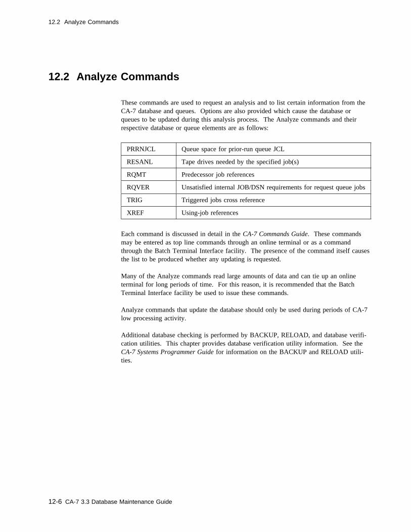
12.2 Analyze Commands
12.2 Analyze Commands
These commands are used to request an analysis and to list certain information from theCA-7 database and queues. Options are also provided which cause the database orqueues to be updated during this analysis process. The Analyze commands and theirrespective database or queue elements are as follows:
Each command is discussed in detail in the CA-7 Commands Guide. These commandsmay be entered as top line commands through an online terminal or as a commandthrough the Batch Terminal Interface facility. The presence of the command itself causesthe list to be produced whether any updating is requested.
Many of the Analyze commands read large amounts of data and can tie up an onlineterminal for long periods of time. For this reason, it is recommended that the BatchTerminal Interface facility be used to issue these commands.
Analyze commands that update the database should only be used during periods of CA-7low processing activity.
Additional database checking is performed by BACKUP, RELOAD, and database verifi-cation utilities. This chapter provides database verification utility information. See theCA-7 Systems Programmer Guide for information on the BACKUP and RELOAD utili-ties.
PRRNJCL Queue space for prior-run queue JCL
RESANL Tape drives needed by the specified job(s)
RQMT Predecessor job references
RQVER Unsatisfied internal JOB/DSN requirements for request queue jobs
TRIG Triggered jobs cross reference
XREF Using-job references
12-6 CA-7 3.3 Database Maintenance Guide

Chapter 13. Database Transportability
It may occasionally become necessary or desirable to transfer work from one CA-7 data-base to another. One reason for doing this might be to better balance the workload acrossmultiple data centers. Another might be to move test application(s) into a productiondatabase from a test database. Certainly, there can be other reasons for transferring infor-mation between databases.
The effort required to manually redefine the workload into another database, even withonline preformatted screens, can be sizeable. The amount of time typically available forthis activity is limited. In most cases, a weekend or after-hours is selected; wheneverproduction is relatively inactive. When the database move is done manually, the accuracyis suspect, particularly when it is done hurriedly.
CA-7 provides database transportability programs which, in batch mode and with theBatch Terminal Interface (BTI) facility, provide assistance in transfers of workload defi-nitions.
The transportability process uses standard CA-7 inquiry, Batch Terminal Interface (BTI)and Database Maintenance (DBM) facilities to assist the user in relocating workload defi-nitions from one CA-7 database to another or making mass changes. This processassumes that the workload to be moved or changed is in good running condition at theoriginal (sending) site; that is, it is properly defined in the original site's database andpresumably being run (or ready to be run) there on a regular basis.
Moving workload definitions from one database to another is a labor intensive process.The impact on both of the databases can be major. Certainly, the impact on any two (ormore) data centers involved in such a move is major. The movement of:
� application data sets � program libraries
and some other related items are beyond the realm of the functions performed by thedatabase transportability process. This transportability process is only intended to sim-plify the CA-7 database portion of the total effort required. Some of the data sets andcontrol reports generated by this process can be of direct assistance, however, in movingother items such as PROCLIBs.
Chapter 13. Database Transportability 13-1
The workload is placed in the new (receiving) database through various ADD commandsof the standard DBM functions. Therefore, the database which is to receive the defi-nitions of jobs and networks, can initially be empty or may contain definitions of otherwork. When other work already exists in the database, the incoming work is effectivelymerged into the database. The user should be sure that the incoming work does notcreate any conflicts with preexisting work. The incoming work should have uniquenames for:
� jobs � networks � data sets
and other items. Adding the work through DBM ensures that duplications do not occur.
This process does not actually add the work to the database. It simply creates data setswith which the user may perform necessary functions. Some of the data sets containstandard BTI commands for performing DBM functions. Other data sets are for handlingCA-Librarian, CA-Panvalet, and PROCLIB members. (Movement of JCL can be sup-pressed if the user wishes to do that external to this process.)
These command data sets can be used anytime after the user has reviewed and/or alteredthe commands to accomplish the desired results. The data sets can then be used when-ever and wherever they are needed. The data sets must be generated using the originalsite database, wherever it is located. Once created, the data sets can be sent to whateverlocation needs them. Copies of the control reports which correspond to the data setscould also be of value at the new site.
The user may find it helpful as a planning aid to run these jobs, multiple times if neces-sary, just to get the reports which are produced. These reports provide an excellentinventory organized into meaningful groups. That is, cataloged procedures are listed onone report, DBM work on other separate reports, and so forth.
The process could be repeated as many times as necessary to get the correct resultswithout making any updates to any database. Once the user is satisfied that everythinghas been properly considered and provided for, the process can then be run to create thedesired command data sets.
13-2 CA-7 3.3 Database Maintenance Guide

13.1 Assumptions
13.1 Assumptions
Not all of the process is automated. Some manual effort is required to ensure that thetotal problem is properly solved. There are also assumptions made which the user mustconsider when using this process. The following address some of the particular consider-ations for database movement using this process.
Chapter 13. Database Transportability 13-3
13.1 Assumptions
13.1.1 LOAD/RELOAD Status
All CPU jobs must have been LOADed with the current JCL to ensure that all data setsused by the job(s) are properly identified and handled in the move. Any associated dataset documentation, cross-reference information, and so forth, are also dependent on this.Any job which was in RELOAD status at the original site may have some data set relatederrors in the new database definition. This is particularly true if JCL changes reflect datasets not previously used which also have documentation and special characteristics.
13.1.2 CA-11 Step Insertion
Whenever a job is defined in the original site database with INSERT-RMS=Y to causethe CA-11 step to be automatically inserted by CA-7, the job is moved assuming thatCA-11 exists at the new site and the RMS step is to continue to be inserted automatically.
If that is not the case, the final commands must have the INSRTRMS=Y keyword manu-ally edited (by the user) to the correct value before they are processed at the new site.
13.1.3 Base Calendars
This process does not move base calendars. The commands generated to define andresolve calendar schedules assume that the same calendars already exist at the new site.They are further assumed to have the same name(s) as those used at the original site.
The user must manually define the necessary calendars at the new site. If necessary, theBTI commands generated may be manually edited to reflect the correct calendar IDsbefore the BTI run is made.
13.1.4 Calendar Schedules
All calendar oriented schedules are assumed to have been RESOLVed against the properBase Calendar. Without prior schedule resolution, the schedule is not correctly definedby this process. (Any differences in calendar names between the two sites must be manu-ally edited into the BTI commands.)
13.1.5 DB.2.7 Schedule Modifications
This process has no facility to reapply any schedule changes which had been madethrough the DB.2.7 facility. Information on schedules, just as it would appear in LJOBor LSCHD output, is carried forward into the commands generated by this process.DB.2.7 changes have to be reapplied manually.
To assist the user in identifying those jobs which need such modifications reapplied at thenew site, the SASSDT30-02 control report, produced in the last step, includes a warningmessage each time this condition is found. The message appears within a box of aster-isks on the report following the RESOLV command for the job's schedules.
13-4 CA-7 3.3 Database Maintenance Guide

13.1 Assumptions
13.1.6 NXTCYC Settings
In the event that normal scheduling of CPU jobs has been altered by a NXTCYCcommand, that status is carried over to the database at the new site. This is accomplishedby generating the appropriate NXTCYC command into the DBMADDS2 data set.
See the CA-7 Commands Guide for a discussion of the NXTCYC command.
13.1.7 Execution JCL Libraries
This process provides the commands and JCL statements necessary to add the JCL to alibrary at the new site. The execution JCL is added exactly as it appeared in LJCLoutput at the original site except for embedded blank records. Any records that are com-pletely blank in positions 1-80 are ignored. (See 13.9, “Cataloged Procedures” onpage 13-32 for how cataloged procedures are handled.) The commands use the samemember names as those used at the original site.
It is also assumed that the new site uses the same number and types of JCL libraries asthose used at the original site. This is typically the case. Using a different DSORGvalue at the new site makes it more difficult to use the generated commands since theyare generated assuming that the same DSORG is used and the commands are quite dif-ferent depending on the type of library being used.
It is further assumed that the libraries use the same JCLID or JCLLIB values. This isprobably NOT a good assumption since the chance of duplication across two data centersis great, especially in the use of the default ID of zero. However, as long as a one-to-onerelationship exists between the libraries at the two sites, all references to any one libraryin the generated BTI commands can be globally edited to another value to reflect what-ever JCLID or JCLLIB value is used at the new site.
13.1.8 Cataloged Procedures
The user can bypass this feature by specifying JCL=N in the PARM for Job 2.
Otherwise, for each cataloged procedure executed in the production JCL, anIEHPROGM-type SCRATCH command is generated. These commands can optionally beused to delete the procedures at the original site once the move has been done and veri-fied to be correct at the new site.
The list of these generated commands can assist the customer in identifying which cata-loged procedures need to be moved to the PROCLIBs at the new site. Any such move-ment of data must be handled by the customer external to this process. The list is onlyan aid in accomplishing that task.
Chapter 13. Database Transportability 13-5
13.1 Assumptions
13.1.9 In-stream JCL Procedures
Although it is not a common practice for production jobs to use in-stream procedures(bound by PROC and PEND statements in the JCL), this process allows up to 256 suchprocedures within a single job. All other EXEC statements in the production JCL whichexecute procedures are assumed to be executing cataloged procedures and are handled asoutlined in the prior discussion.
13.1.10 Workstation Networks
Only workstation networks directly related to a CPU job, through either a DB.3 or aDB.2.5 function, are automatically moved by this process. If there are other networks tobe moved, they must be handled manually by the user as outlined in 13.4.4, “Uncon-nected Workstation Networks” on page 13-21.
13.1.11 User Level Documentation
Any documentation that was defined through the DB.4.3 screen is ignored by thisprocess. If any such documentation is to be moved with the definition of the jobs, thecustomer must handle that manually, external to this process.
13.1.12 ANALYZE Application
To ensure database accuracy, the TRIG and RQMT functions of CA-7's ANALYZEapplication are performed by the first step of the process, prior to interrogating jobdependencies and predecessor/successor relationships. The RQMT and TRIG commandsare also included at the end of the generated DBM commands which perform deletes atthe original site. This provides a much needed cleanup function following the deletion ofthe work being moved.
In the event of a rerun of this process, it is unnecessary to reexecute these commands atthe original site. The processing time for each of these can be quite lengthy dependingon the size of the database. In the event a rerun becomes necessary, simply delete thosecommands from the generated data set prior to executing the BTI run which uses them.
13.1.13 Commas in the Data
Since the information in the database is moved using BTI facilities, the use of commas insome of the data fields creates conflicts with the syntax requirements of batch commands.To help avoid such conflicts, this process replaces commas with blanks whenever they arefound embedded within any of these data fields:
User requirements (see DB.3.6)REPORT-ID value for documentationDESC value for documentation
If any such commas are required in the workload definition, they have to be manuallyreinserted in the new database after the data has been moved.
13-6 CA-7 3.3 Database Maintenance Guide
13.1 Assumptions
13.1.14 Sequence Numbers
All of the commands generated by this process are sequence numbered in positions 75-80.The characters U7 are also in positions 73-74 of the commands. All sequence numbersthat previously existed within JCL statements are preserved by this process. That is,wherever a JCL member is embedded within the generated commands, the generatedsequence is interrupted by the original JCL statements, all 80 positions. This should beconsidered when browsing the generated command data sets. Control reports listing thegenerated commands reflect the records, including sequence numbers, as they appearwithin the data sets. Each data set has its own range of sequence numbers.
13.1.15 User ID Security
All CPU jobs moved by this process carry the same User ID value to the new database.(See the UID field on the DB.1 screen on User ID on page 2-5 for more details on thisfacility.) If any of the jobs being moved create any conflicts with other User IDs in thenew database, such conflicts must be resolved manually by the user before the generatedcommands are processed into the new database. New ID values could be manually editedinto the generated commands any time before they are processed.
13.1.16 LINKed Documentation
Any documentation linked using the LINK field on any of the DB.4 screens cannot belinked by this process since the documentation number must be known at the time theadd is done. It is assumed that the linked documentation is moved as some other piece ofthis process and any linked documentation which shows up during this process is ignoredon that basis. The user must ensure that any linked documentation gets moved as part ofsome other job, system, and so forth. The linking of the documentation members thenalso has to be done manually after the adds have been made at the new site.
Chapter 13. Database Transportability 13-7
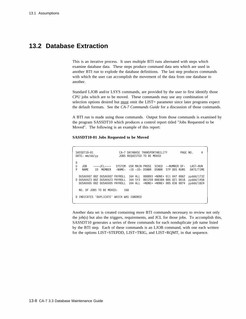
13.1 Assumptions
13.2 Database Extraction
This is an iterative process. It uses multiple BTI runs alternated with steps whichexamine database data. These steps produce command data sets which are used inanother BTI run to explode the database definitions. The last step produces commandswith which the user can accomplish the movement of the data from one database toanother.
Standard LJOB and/or LSYS commands, are provided by the user to first identify thoseCPU jobs which are to be moved. These commands may use any combination ofselection options desired but must omit the LIST= parameter since later programs expectthe default formats. See the CA-7 Commands Guide for a discussion of those commands.
A BTI run is made using those commands. Output from those commands is examined bythe program SASSDT10 which produces a control report titled "Jobs Requested to beMoved". The following is an example of this report:
SASSDT10-01 Jobs Requested to be Moved
� �SASSDT1�-�1 CA-7 DATABASE TRANSPORTABILITY PAGE NO. 4
DATE: mm/dd/yy JOBS REQUESTED TO BE MOVED
D
U JOB ----JCL---- SYSTEM USR MAIN PROSE SCHED --NUMBER OF- LAST-RUN
P NAME ID MEMBER -NAME- -ID -ID- DSNBR DSNBR STP DDS RUNS DATE/TIME
DUSAXX�7 ��2 DUSAXX�7 PAYROLL 164 ALL ���893 CNONEC �11 �47 ��62 yyddd/1732
D DUSAXX23 ��2 DUSAXX23 PAYROLL 164 SY3 ��1259 ���384 ��5 �21 ��18 yyddd/1456
DUSAXX�5 ��2 DUSAXX�5 PAYROLL 164 ALL CNONEC CNONEC ��5 �36 ��74 yyddd/1824
NO. OF JOBS TO BE MOVED: 168
D INDICATES 'DUPLICATE' WHICH WAS IGNORED
( )
Another data set is created containing more BTI commands necessary to review not onlythe job(s) but also the triggers, requirements, and JCL for those jobs. To accomplish this,SASSDT10 generates a series of three commands for each nonduplicate job name listedby the BTI step. Each of these commands is an LJOB command, with one each writtenfor the options LIST=STEPDD, LIST=TRIG, and LIST=RQMT, in that sequence.
13-8 CA-7 3.3 Database Maintenance Guide

13.2 Database Extraction
It is this examination of the triggers and requirements which makes it possible for theprogram to automatically include any workstation networks which are needed by thesejobs. This also allows the program to look one level in each direction from the requestedjobs to help ensure that all related jobs are being moved. Jobs overlooked in the initialLJOB and/or LSYS commands are thus included in the final output as long as they wereno more than one level removed from the requested job.
After another BTI run, using the commands generated by SASSDT10, another program,SASSDT20, examines the output and creates yet another data set of BTI commands to listall of the database information that is needed to allow the work to be redefined intoanother database. These commands are then the input to another BTI run.
Another control report is produced that indicates which commands were generated in thisstep for each workload component to be moved. The commands generated bySASSDT20 are listed beneath the command generated by SASSDT10 which listed thecomponent to be moved. If no commands were generated for any of the incoming com-mands, the characters **NONE** appear.
SSASSDT20-01 Expansion of Requested Jobs
� �SASSDT2�-�1 CA-7 DATABASE TRANSPORTABILITY PAGE NO. 29
DATE: mm/dd/yy EXPANSION OF REQUESTED JOBS
JOB-NAME
C- COMMANDS GENERATED -------------------------------------------C SEQ.-NO.
DUSAXX�5 (LIST=STEPDD)
LPROS,SYS=PAYROLL U7��1722
LJOB,JOB=DUSAXX�5,LIST=ALL U7��1723
LJCL,JOB=DUSAXX�5 U7��1724
LPROS,JOB=DUSAXX�5 U7��1725
LPROS,JOB=DUSAXX�5,STEP=STEP��5�,DD=HISTFILE U7��1726
LDSN,DSNBR=DS��8162,LIST=TRIG U7��1727
LPROS,DSN=PAYROLL.HOURLY.HISTORY.DETAIL U7��1728
LNTWK,NW=TIMECARD,LIST=ALL U7��1729
LPROS,NW=TIMECARD U7��173�
DUSAXX�5 (LIST=TRIG)
CCNONECC
DUSAXX�5 (LIST=RQMT)
LJOB,JOB=DUSAXX�9,LIST=ALL U7��1731
LJCL,JOB=DUSAXX�9 U7��1732
LPROS,JOB=DUSAXX�9 U7��1733
( )
Chapter 13. Database Transportability 13-9
13.2 Database Extraction
To assist the user with the separate task of getting all of the necessary data sets phys-ically moved to the new site, a file of all data set names used by the jobs being moved isalso produced by SASSDT20. The ddname of this file is DATASETS. This is a card-image data set containing the data set names beginning in position 1 of each record. Allrecords written to this data set contain a data set name. (No heading lines.) The recordsare produced as the unique data set names occur in the data and therefore are not in anyparticular meaningful sequence. The file produced can be listed as is or could be sortedin data set name sequence prior to printing if desired.
Another BTI job is run using BTI commands produced by SASSDT20. When that runhas completed, the output produced contains all of the information needed to generatecommands with which the user can perform the move. The output from this BTI run isused as input to the last program in this process, SASSDT30. Several card-image datasets are created by SASSDT30.
Some of these are BTI data sets containing DBM commands, others are for handling JCLlibraries and are in another format.
There are two data sets containing add type commands for the new CA-7 database. Thatis necessary since the processing sequence of the commands is not the same as thesequence in which the data becomes available to the programs which generate the com-mands. For example, a JOBCONN function must await the definition of both the con-nected items in the database before it can be performed. The user must process these twodata sets in the correct sequence at the new site to ensure correct definition of the workin the database.
These data sets can be used whenever and wherever they are needed to accomplish theappropriate database activity. They probably require several changes which the user mustmake manually, using some text editor. Each data set created has a corresponding controlreport to allow the user to review the data before making any changes.
The following figure shows how the final commands produced evolve from the initialsimple commands, with each one feeding subsequent commands. This sequence of com-mands, the same sequence that would be required to manually examine the workload fora move done without this process, could be repeated at an online CA-7 terminal to verifythis process.
13-10 CA-7 3.3 Database Maintenance Guide
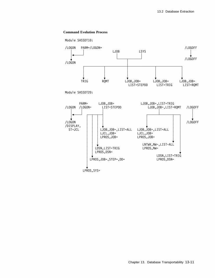
13.2 Database Extraction
Command Evolution Process
Module SASSDT1�:
/LOGON PARM=/LOGON= /LOGOFF
│ │ LJOB LSYS │
│c─────┘ │ │ f
f └─────┬───────┘ /LOGOFF
/LOGON │
┌───────────┬────────────┼───────────────┬──────────────┐
│ │ │ │ │
│ │ │ │ │
f f f f f
TRIG RQMT LJOB,JOB= LJOB,JOB= LJOB,JOB=
LIST=STEPDD LIST=TRIG LIST=RQMT
Module SASSDT2�:
PARM= LJOB,JOB= LJOB,JOB=,LIST=TRIG
/LOGON /LOGON= LIST=STEPDD LJOB,JOB=,LIST=RQMT /LOGOFF
│ │ │ │ │
│c────┘ ┌──┬──┬──┤ ┌──────┴───────┬───┐ │
f │ │ │ │ │ │ │ f
/LOGON │ │ │ │ │ │ │ /LOGOFF
/DISPLAY, │ │ │ f f │ │
ST=JCL │ │ │ LJOB,JOB=,LIST=ALL LJOB,JOB=,LIST=ALL │ │
│ │ │ LJCL,JOB= LJCL,JOB= │ │
│ │ │ LPROS,JOB= LPROS,JOB= │ │
│ │ │ f │
│ │ f LNTWK,NW=,LIST=ALL │
│ │ LDSN,LIST=TRIG LPROS,NW= │
│ │ LPROS,DSN= f
│ f LDSN,LIST=TRIG
│ LPROS,JOB=,STEP=,DD= LPROS,DSN=
│
f
LPROS,SYS=
Chapter 13. Database Transportability 13-11

13.2 Database Extraction
Module SASSDT3�:
PARM= LJOB,JOB=,LIST=NODD /LOGOFF
/LOGON /LOGON= │ │
│ │ │ /DISPLAY f
│c───┘ │ LJCL,JOB= RQMT
f │ │ TRIG
/LOGON │ │ LDSN,LIST=TRIG /LOGOFF
│ │ │
┌───────────────┘ │ │ LNTWK,NW=, LPROS,JOB=
│ │ └──┬────┐ │ LIST=ALL LPROS,DSN=
│ ┌──────┬─┬────┬─┬─┬┴────┬───┐ │ │ │ LPROS,SYS=
│ │ │ │ │ │ │ │ │ f │ │ LPROS,NW=
│ f │ │ │ │ │ f │ DSN │ │ LPROS,JOB=,STEP=,DD=
│ JCL │ │ │ │ │ SCRATCH │ ADD, │ │ │
│ DELETE │ │ │ │ │ ┌───┘ ┌────┘ │ ┌─────┴──────┐
│ ┌───┘ f │ │ │ │ │ │ │ │
│ │ DBM │ │ │ f f │ f f
│ f LOAD, │ │ │ -DLM SCHD │ PROSE PROSE
│ JCL JOB= │ │ └──────┐ TRGR │ DELETE,SYS EDIT
│ EDIT │ │ │ UPD,DTRG │ I ,
│ I , ┌─┘ │ f │ ...
│ ... │ │ ++STATUS,DISABLE │ $IEND
│ $IEND f └────────┐ │ XSEQ
│ XSEQ -OPT │ │ SAVE
│ SAVE -ADD f │ SAVE,type
│ SAVE, ... ++ADD,DATA │ DESC=
│ ─EMOD │ FORM=,...
│ ┌──────────────┬─────────┬───────────┴──┬────────────────┐ REPORT
│ │ │ │ │ │ CLEAR
│ f f f f f
│ NETWORK NETWORK SCHD SCHD SCHD
│ ADD, DELETE ONWK INWK INWK
│ STAT= EDIT,NETWORK= FETCH,NETWORK= EDIT,NETWORK=
│ ADD,SCHID= REPL ADD,SCHID=
│ SAVE SAVE
│ SAVE,NETWORK= SAVE,NETWORK=
└─┬─┬──┬────┬───────┬─┬─┬─────────┬────────┬─┬───────────┐ DBM
│ │ │ │ │ │ │ │ │ │ │ RESOLV
│ │ f │ │ │ f │ │ f f
│ │ JOB │ │ │ JOBCONN │ │ SCHD SCHD
│ │ UPD │ │ │ UPD,JDEP │ │ TRGR JOB
│ f │ │ f │ │ UPD,JTRG EDIT
│ JOB │ │ JOBCONN │ f ADD,SCHID=
│ DELETE │ │ UPD,DSN │ SCHD SAVE
f f f f TRGR SAVE,JOB=
JOB DBM JOBCONN JOBCONN UPD,NTRG DBM
ADD NXTCYC, UPD,NWK UPD,USR RESOLV
The following topics discuss the specific types of workload definitions handled by thisprocess and describe what is produced to allow the workload definitions to be moved.
13-12 CA-7 3.3 Database Maintenance Guide
13.3 CPU Jobs
13.3 CPU Jobs
13.3.1 Adding at New Site
For each CPU job to be moved, a set of commands is generated into the DBMADDS1data set to perform the necessary DBM JOB function. Those commands are generated asfollows:
JOB
ADD,jobname,.........keywords and values...............,
.
................more keywords and values...............,
.
See 2.1, “Adding a Job” on page 2-2 and 2.2, “DB.1 - CPU Job Definition Screen” onpage 2-3 for further explanation of the content and requirements for these commands.
Some historical information such as number of times run and number of times late arenot carried forward to the new site since there are no DB.1 screen input fields for thosevalues. The average CPU and elapsed time requirements are carried forward.
There are a number of keywords which may be required to complete the definition of ajob. Many of the available parameters are optional.
To minimize the number of parameters used, most parameters are not included in thegenerated commands if the value equals the usual CA-7 default. Multiple records maystill be required to accommodate all of the needed keywords and values. Normal BTIcontinuation conventions are observed for those records.
The LOAD function needs to be performed for each of the jobs sometime after they aredefined at the new site; therefore, the keyword RELOAD is included for all jobs with avalue of Y (that is, RELOAD=Y). This allows the jobs to be defined at the new sitewithout having to do a LOAD on each one of them at the time they are defined. Thisdefers that process until the job runs for the first time at the new site. If the number ofjobs is very high, it would take considerable time to perform individual LOADs all atonce.
Since it is likely that the JCL library ID values are different at the new site, ADD com-mands for all CPU job definitions include the keyword JCLID, even if the default ID ofzero was used. This makes it easier for the user to apply global changes to the com-mands if necessary.
These commands are sequence numbered in positions 73 through 80. They are also listed(with other DBM add functions for other related components being moved) on the
Chapter 13. Database Transportability 13-13
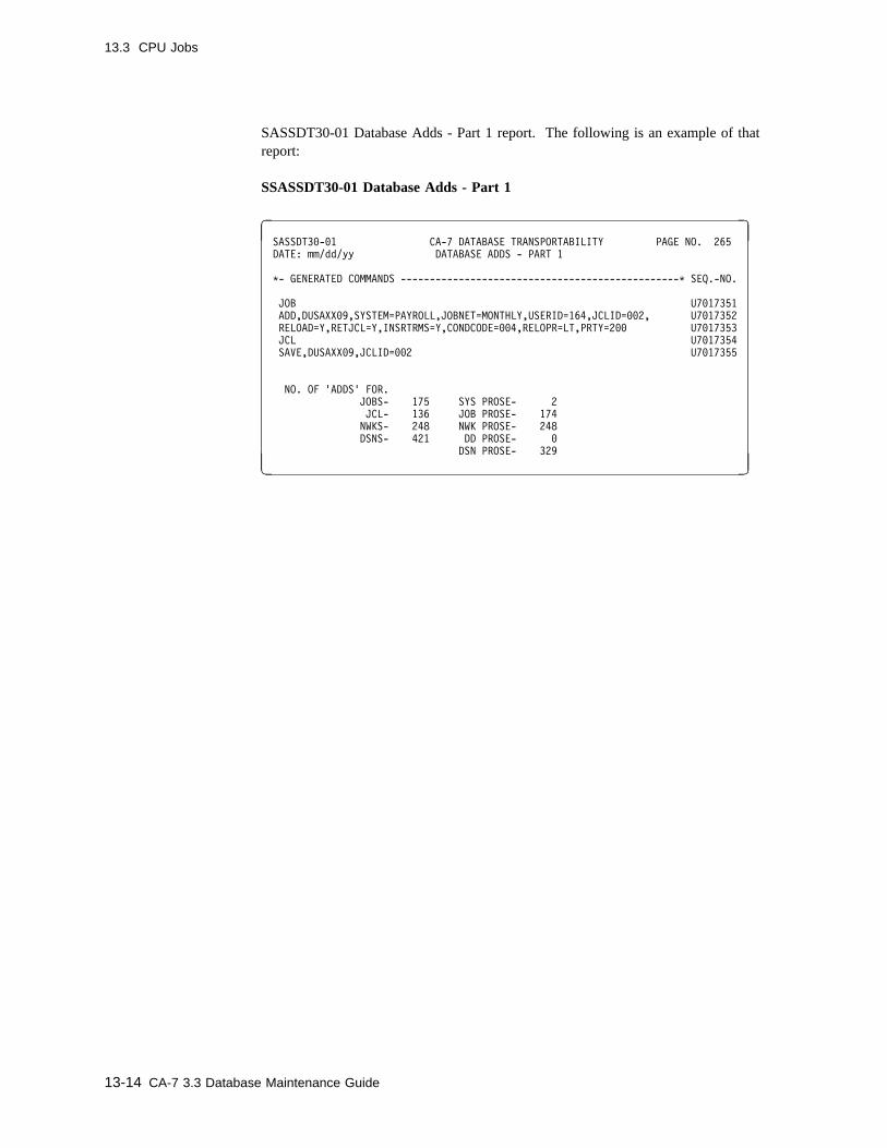
13.3 CPU Jobs
SASSDT30-01 Database Adds - Part 1 report. The following is an example of thatreport:
SSASSDT30-01 Database Adds - Part 1
� �SASSDT3�-�1 CA-7 DATABASE TRANSPORTABILITY PAGE NO. 265
DATE: mm/dd/yy DATABASE ADDS - PART 1
C- GENERATED COMMANDS ------------------------------------------------C SEQ.-NO.
JOB U7�17351
ADD,DUSAXX�9,SYSTEM=PAYROLL,JOBNET=MONTHLY,USERID=164,JCLID=��2, U7�17352
RELOAD=Y,RETJCL=Y,INSRTRMS=Y,CONDCODE=��4,RELOPR=LT,PRTY=2�� U7�17353
JCL U7�17354
SAVE,DUSAXX�9,JCLID=��2 U7�17355
NO. OF 'ADDS' FOR.
JOBS- 175 SYS PROSE- 2
JCL- 136 JOB PROSE- 174
NWKS- 248 NWK PROSE- 248
DSNS- 421 DD PROSE- �
DSN PROSE- 329
( )
13-14 CA-7 3.3 Database Maintenance Guide
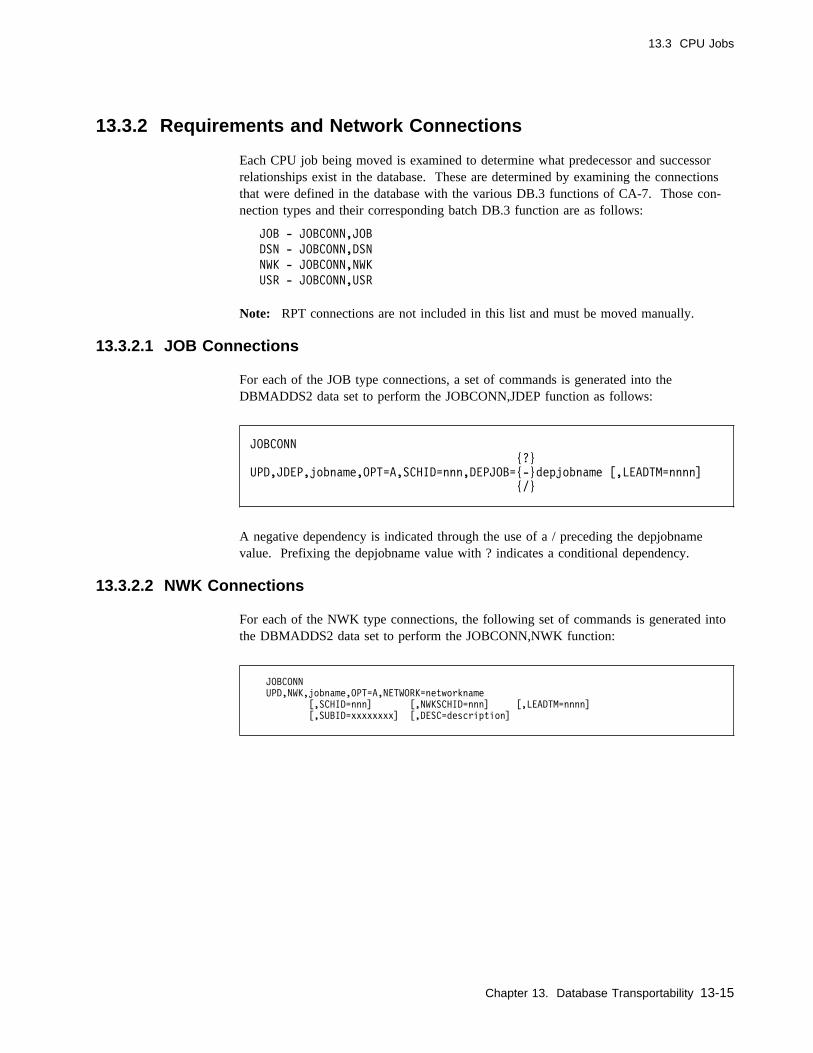
13.3 CPU Jobs
13.3.2 Requirements and Network Connections
Each CPU job being moved is examined to determine what predecessor and successorrelationships exist in the database. These are determined by examining the connectionsthat were defined in the database with the various DB.3 functions of CA-7. Those con-nection types and their corresponding batch DB.3 function are as follows:
JOB - JOBCONN,JOB
DSN - JOBCONN,DSN
NWK - JOBCONN,NWK
USR - JOBCONN,USR
Note: RPT connections are not included in this list and must be moved manually.
13.3.2.1 JOB Connections
For each of the JOB type connections, a set of commands is generated into theDBMADDS2 data set to perform the JOBCONN,JDEP function as follows:
JOBCONN
{?}
UPD,JDEP,jobname,OPT=A,SCHID=nnn,DEPJOB={-}depjobname [,LEADTM=nnnn]
{/}
A negative dependency is indicated through the use of a / preceding the depjobnamevalue. Prefixing the depjobname value with ? indicates a conditional dependency.
13.3.2.2 NWK Connections
For each of the NWK type connections, the following set of commands is generated intothe DBMADDS2 data set to perform the JOBCONN,NWK function:
JOBCONN
UPD,NWK,jobname,OPT=A,NETWORK=networkname
[,SCHID=nnn] [,NWKSCHID=nnn] [,LEADTM=nnnn]
[,SUBID=xxxxxxxx] [,DESC=description]
Chapter 13. Database Transportability 13-15
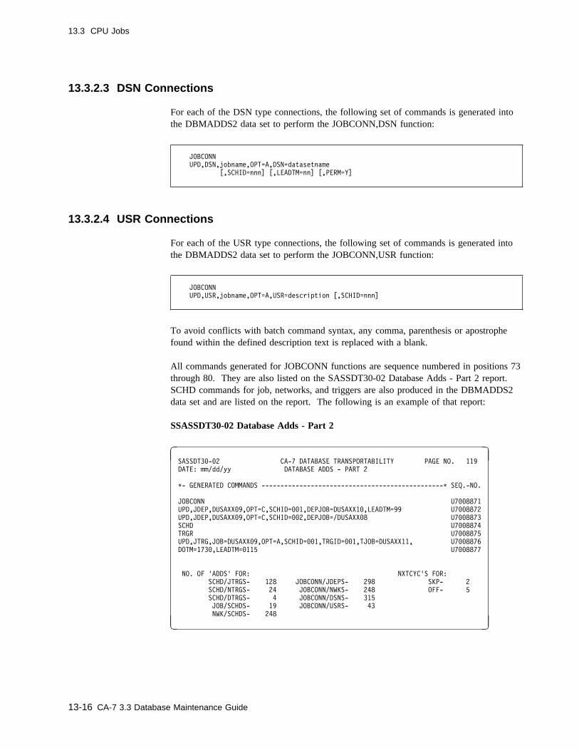
13.3 CPU Jobs
13.3.2.3 DSN Connections
For each of the DSN type connections, the following set of commands is generated intothe DBMADDS2 data set to perform the JOBCONN,DSN function:
JOBCONN
UPD,DSN,jobname,OPT=A,DSN=datasetname
[,SCHID=nnn] [,LEADTM=nn] [,PERM=Y]
13.3.2.4 USR Connections
For each of the USR type connections, the following set of commands is generated intothe DBMADDS2 data set to perform the JOBCONN,USR function:
JOBCONN
UPD,USR,jobname,OPT=A,USR=description [,SCHID=nnn]
To avoid conflicts with batch command syntax, any comma, parenthesis or apostrophefound within the defined description text is replaced with a blank.
All commands generated for JOBCONN functions are sequence numbered in positions 73through 80. They are also listed on the SASSDT30-02 Database Adds - Part 2 report.SCHD commands for job, networks, and triggers are also produced in the DBMADDS2data set and are listed on the report. The following is an example of that report:
SSASSDT30-02 Database Adds - Part 2
� �SASSDT3�-�2 CA-7 DATABASE TRANSPORTABILITY PAGE NO. 119
DATE: mm/dd/yy DATABASE ADDS - PART 2
C- GENERATED COMMANDS ------------------------------------------------C SEQ.-NO.
JOBCONN U7��8871
UPD,JDEP,DUSAXX�9,OPT=C,SCHID=��1,DEPJOB=DUSAXX1�,LEADTM=99 U7��8872
UPD,JDEP,DUSAXX�9,OPT=C,SCHID=��2,DEPJOB=/DUSAXX�8 U7��8873
SCHD U7��8874
TRGR U7��8875
UPD,JTRG,JOB=DUSAXX�9,OPT=A,SCHID=��1,TRGID=��1,TJOB=DUSAXX11, U7��8876
DOTM=173�,LEADTM=�115 U7��8877
NO. OF 'ADDS' FOR: NXTCYC'S FOR:
SCHD/JTRGS- 128 JOBCONN/JDEPS- 298 SKP- 2
SCHD/NTRGS- 24 JOBCONN/NWKS- 248 OFF- 5
SCHD/DTRGS- 4 JOBCONN/DSNS- 315
JOB/SCHDS- 19 JOBCONN/USRS- 43
NWK/SCHDS- 248
( )
13-16 CA-7 3.3 Database Maintenance Guide

13.3 CPU Jobs
13.3.3 Deleting at Original Site
For each job being moved, the following set of commands is generated into theDBMDELTS data set to perform the DBM JOB deletion function at the original site:
JOB
DELETE,jobname
The commands are sequence numbered in positions 73 through 80 and listed on theSASSDT30-03 Database Deletes report. See SASSDT30-03 Database Deletes Report onpage 13-17 for a sample of that report. Some other deletion functions are also listed onthat report since their commands are written to the DBMDELTS data set.
Deletion of the JCL for the job is performed separately with another set of commands.Deletion of associated documentation and schedules occurs automatically when the job isdeleted at the original site.
The DB.1 screen function DD not only deletes a job but also definitions of any data setsfor which this job was the last "using-job" reference. If the user wishes to use that func-tion instead of the default DELETE function, the JOBDD keyword must be specified inthe PARM data for Job 3 as discussed in 13.12.3, “Job 3” on page 13-46.
SASSDT30-03 Database Deletes
� �SASSDT3�-�3 CA-7 DATABASE TRANSPORTABILITY PAGE NO. 18
DATE: mm/dd/yy DATABASE DELETES
C- GENERATED COMMANDS ------------------------------------------------- SEQ.-NO.
JOB U7��1119
DELETE,DUSAXX�9 U7��112�
JCL U7��1121
DELETE,DUSAXX�9,DSN=PAYROLL.JCLLIB,VOL=M8���7 U7��1122
NO. OF 'DELETES' FOR:
JOBS- 175
JCL- 136
NWKS- 248
SYS/PROSE- 2
( )
Chapter 13. Database Transportability 13-17
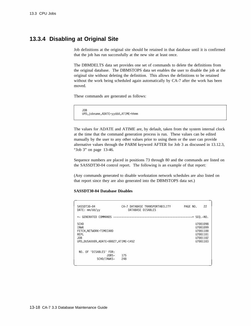
13.3 CPU Jobs
13.3.4 Disabling at Original Site
Job definitions at the original site should be retained in that database until it is confirmedthat the job has run successfully at the new site at least once.
The DBMDELTS data set provides one set of commands to delete the definitions fromthe original database. The DBMSTOPS data set enables the user to disable the job at theoriginal site without deleting the definition. This allows the definitions to be retainedwithout the work being scheduled again automatically by CA-7 after the work has beenmoved.
These commands are generated as follows:
JOB
UPD,jobname,ADATE=yyddd,ATIME=hhmm
The values for ADATE and ATIME are, by default, taken from the system internal clockat the time that the command generation process is run. These values can be editedmanually by the user to any other values prior to using them or the user can providealternative values through the PARM keyword AFTER for Job 3 as discussed in 13.12.3,“Job 3” on page 13-46.
Sequence numbers are placed in positions 73 through 80 and the commands are listed onthe SASSDT30-04 control report. The following is an example of that report:
(Any commands generated to disable workstation network schedules are also listed onthat report since they are also generated into the DBMSTOPS data set.)
SASSDT30-04 Database Disables
� �SASSDT3�-�4 CA-7 DATABASE TRANSPORTABILITY PAGE NO. 22
DATE: mm/dd/yy DATABASE DISABLES
C- GENERATED COMMANDS ------------------------------------------------C SEQ.-NO.
SCHD U7��1�98
INWK U7��1�99
FETCH,NETWORK=TIMECARD U7��11��
REPL U7��11�1
JOB U7��11�2
UPD,DUSAXX�9,ADATE=���27,ATIME=1452 U7��11�3
NO. OF 'DISABLES' FOR:
JOBS- 175
SCHD/INWKS- 248
( )
13-18 CA-7 3.3 Database Maintenance Guide

13.4 Workstation Networks
13.4 Workstation Networks
Workstation networks, both preprocessing and postprocessing, are handled by this processimplicitly when a network is either connected to a CPU job being moved or triggers theexecution of a CPU job being moved. (Only CPU jobs must be requested explicitly bythe user for movement.)
If any workstation networks do not meet these criteria but must be moved, they must bemoved manually by the user using the guidelines outlined in 13.4.4, “Unconnected Work-station Networks” on page 13-21.
13.4.1 Adding at New Site
For each network to be moved, commands to perform the DBM NETWORK function aregenerated into the DBMADDS1 data set as follows:
NETWORK
ADD,networkname,type,SUBID=subidvalue,JOB=jobname,
STAT=(stationname1,stationname2,...,stationname9)
See 8.1, “Adding a Network” on page 8-2 and 8.2, “DB.5 - Input/Output Network Defi-nition Screen” on page 8-3 for further explanation of these commands. The values forthese parameters are taken from information listed during an intermediate step of thisprocess with a LNTWK command with the LIST=ALL option. See the CA-7 CommandsGuide for a discussion of that command.
Each of these commands are sequence numbered in positions 73 through 80 and each arelisted on the SASSDT30-01 control report. See SASSDT30-01 Database Adds - Part 1Report on page 13-14 for an example of that report.
Chapter 13. Database Transportability 13-19
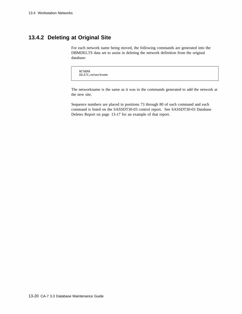
13.4 Workstation Networks
13.4.2 Deleting at Original Site
For each network name being moved, the following commands are generated into theDBMDELTS data set to assist in deleting the network definition from the originaldatabase:
NETWORK
DELETE,networkname
The networkname is the same as it was in the commands generated to add the network atthe new site.
Sequence numbers are placed in positions 73 through 80 of each command and eachcommand is listed on the SASSDT30-03 control report. See SASSDT30-03 DatabaseDeletes Report on page 13-17 for an example of that report.
13-20 CA-7 3.3 Database Maintenance Guide

13.4 Workstation Networks
13.4.3 Disabling at Original Site
13.4.3.1 Input Workstation Networks
There is no "don't schedule after" facility for workstation networks. The way to preventnetworks from being scheduled again at the original site is to unRESOLVe the schedulesfor the networks in that database.
To accomplish this, one set of commands to perform the SCHD,INWK replace function isgenerated into the DBMSTOPS data set as follows:
SCHD
INWK
FETCH,NETWORK=networkname
REPL
These commands are sequence numbered in positions 73 through 80 and are listed on theSASSDT30-04 control report. See SASSDT30-04 Database Disables Report onpage 13-18 for an example of that report.
13.4.3.2 Output Workstation Networks
Since schedules for output workstation networks are based on the associated CPU jobbeing scheduled and the CPU jobs are disabled through another set of commands, noother commands are required to disable these networks at the original site.
13.4.4 Unconnected Workstation Networks
To include any workstation networks which cannot be automatically included based on aconnection or trigger definition, add two commands to the input (SYSIN DD) to 13.12.3,“Job 3” on page 13-46, as follows:
LNTWK,NW=networkname,LIST=ALL
LPROS,NW=networkname
Include one set of commands for each unique network name to be included in the move.See Command Evolution Process on page 13-11 and the discussion 13.12, “CreatingCommand Files” on page 13-41 for more information on these facilities.
Chapter 13. Database Transportability 13-21
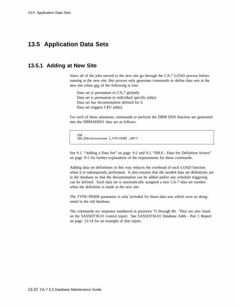
13.5 Application Data Sets
13.5 Application Data Sets
13.5.1 Adding at New Site
Since all of the jobs moved to the new site go through the CA-7 LOAD process beforerunning at the new site, this process only generates commands to define data sets at thenew site when any of the following is true:
Data set is permanent to CA-7 globallyData set is permanent to individual specific job(s)Data set has documentation defined for itData set triggers CPU job(s)
For each of these situations, commands to perform the DBM DSN function are generatedinto the DBMADDS1 data set as follows:
DSN
ADD,DSN=datasetname [,TYPE=PERM] ,SMF=Y
See 9.1, “Adding a Data Set” on page 9-2 and 9.2, “DB.6 - Data Set Definition Screen”on page 9-5 for further explanation of the requirements for these commands.
Adding data set definitions in this way reduces the overhead of each LOAD functionwhen it is subsequently performed. It also ensures that the needed data set definitions arein the database so that the documentation can be added and/or any schedule triggeringcan be defined. Each data set is automatically assigned a new CA-7 data set numberwhen the definition is made at the new site.
The TYPE=PERM parameter is only included for those data sets which were so desig-nated in the old database.
The commands are sequence numbered in positions 73 through 80. They are also listedon the SASSDT30-01 control report. See SASSDT30-01 Database Adds - Part 1 Reporton page 13-14 for an example of that report.
13-22 CA-7 3.3 Database Maintenance Guide
13.5 Application Data Sets
13.5.2 Deleting at Original Site
There are no commands generated to delete data set definitions at the original site. Effec-tive with Version 2.8 of CA-7, the DB.1 screen has a function value of DD available.That function causes data set definitions to be deleted from the database at job deletiontime if the job being deleted is the last "using-job" reference to the data sets.
If such a deletion is important:
� The JOBDD keyword can be used in the third job of the generation process, or� The generated commands to delete jobs from the database at the original site can be
manually edited to replace the function value DELETE with DD prior to using thegenerated commands.
13.12.2, “Job 2” on page 13-44 produces a file of data set names on the data set refer-enced by the ddname of DATASETS. This file contains one record for each unique dataset name which is being moved by this process.
Such a file becomes a source from which batch commands could be produced to performany desired deletions of data set definitions at the original site. A data set similar to anyof the BTI data sets created by this process to do DBM functions could be produced andprocessed to clean up the original database once the definitions were no longer needed.
Chapter 13. Database Transportability 13-23
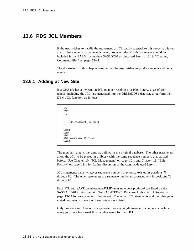
13.6 PDS JCL Members
13.6 PDS JCL Members
If the user wishes to handle the movement of JCL totally external to this process, withoutany of these reports or commands being produced, the JCL=N parameter should beincluded in the PARM for module SASSDT20 as discussed later in 13.12, “CreatingCommand Files” on page 13-41.
The discussions in this chapter assume that the user wishes to produce reports and com-mands.
13.6.1 Adding at New Site
If a CPU job has an execution JCL member residing in a PDS library, a set of com-mands, including the JCL, are generated into the DBMADDS1 data set, to perform theDBM JCL function, as follows:
JCL
EDIT
I ,
.
.
. (JCL statements go here)
.
.
$IEND
XSEQ
SAVE
SAVE,membername,JCLID=nnn
CLEAR
The member name is the same as defined in the original database. The other parametersallow the JCL to be placed in a library with the same sequence numbers that existedbefore. See Chapter 10, “JCL Management” on page 10-1 and Chapter 11, “EditFacility” on page 11-1 for further discussion of the commands used here.
JCL statements carry whatever sequence numbers previously existed in positions 73through 80. The other statements are sequence numbered consecutively in positions 73through 80.
Each JCL and SAVE,membername,JCLID=nnn statement produced are listed on theSASSDT30-01 control report. See SASSDT30-01 Database Adds - Part 1 Report onpage 13-14 for an example of that report. The actual JCL statements and the other gen-erated commands in each of these sets are not listed.
Only one such set of records is generated for any single member name no matter howmany jobs may have used this member name for their JCL.
13-24 CA-7 3.3 Database Maintenance Guide

13.6 PDS JCL Members
The JCL for jobs that already include a $IEND cannot be moved with DBT. This JCLhas to be copied externally from the DBT process.
13.6.2 Deleting at Original Site
Each JCL member copied into the DBMADDS1 data set for moving to a new site alsohas commands generated into the DBMDELTS data set to assist the user in cleaning upthe JCL libraries at the original site. The commands are in the following format:
JCL
DELETE,membername,DSN=datasetname,VOL=volser#
The membername is the member name used in the database. Values for DSN= andVOL= are taken from the definitions of the JCL libraries defined to CA-7.
These commands are sequence numbered in positions 73 through 80 in the DBMDELTSdata set. Generated commands also are listed on the SASSDT30-03 control report. SeeSASSDT30-03 Database Deletes Report on page 13-17 for an example of that report.
Only one set of commands is generated for any single member name no matter howmany jobs may have used this member name for their JCL.
Chapter 13. Database Transportability 13-25

13.7 CA-Librarian JCL
13.7 CA-Librarian JCL
If the user wishes to handle the movement of JCL totally external to this process, withoutany of these reports or commands being produced, the JCL=N parameter should beincluded in the PARM for module SASSDT20 as discussed in 13.12, “Creating CommandFiles” on page 13-41.
The discussions in this chapter assume that the user wishes to produce reports and com-mands.
13.7.1 Adding at New Site
If a CPU job has an execution JCL member residing in a CA-Librarian library, a set ofrecords, including the JCL, is placed in the LIBRADDS data set as follows:
-OPT NOINDEX,NORESEQ
-ADD membername,NOEXEC,NOLIST,NOPUNCH,SEQ=/73,8,1�,1�/
.
.
. (JCL statements go here)
.
.
-EMOD
The member name is the same as it was defined in the original database. See theCA-Librarian publications for the meanings of the various commands and parametersused here. -OPT, -ADD, and -EMOD statements are sequence numbered consecutively,in positions 73 through 80. JCL statements, with their own original sequence numbersare interspersed with these in the LIBRADDS data set. If the original sequence numbersare desired at the new site, the user must manually delete the SEQ parameter from the-ADD statement.
-OPT and -ADD statements produced are listed on the SASSDT30-06 control reportwhich is produced on the file referenced by the ddname DT30CR06. The actual JCLstatements and the -EMOD statements are not listed. See SASSDT30-06 CA-LibrarianJCL Member Adds Report on page 13-27 for a sample of the SASSDT30-06 report.
Any other CA-Librarian control statements can be added to this data set prior to using itat the new site. Since CA-7 does not provide update access to CA-Librarian libraries, theuser must assemble whatever job is needed to add this JCL to another CA-Librarianlibrary at the new site. See the CA-Librarian publications to determine how this is done.
The new library at the new site and the JCLID or JCLLIB values in the JOB commandsgenerated for the jobs which use this JCL must be coordinated to ensure correct defi-nitions.
13-26 CA-7 3.3 Database Maintenance Guide
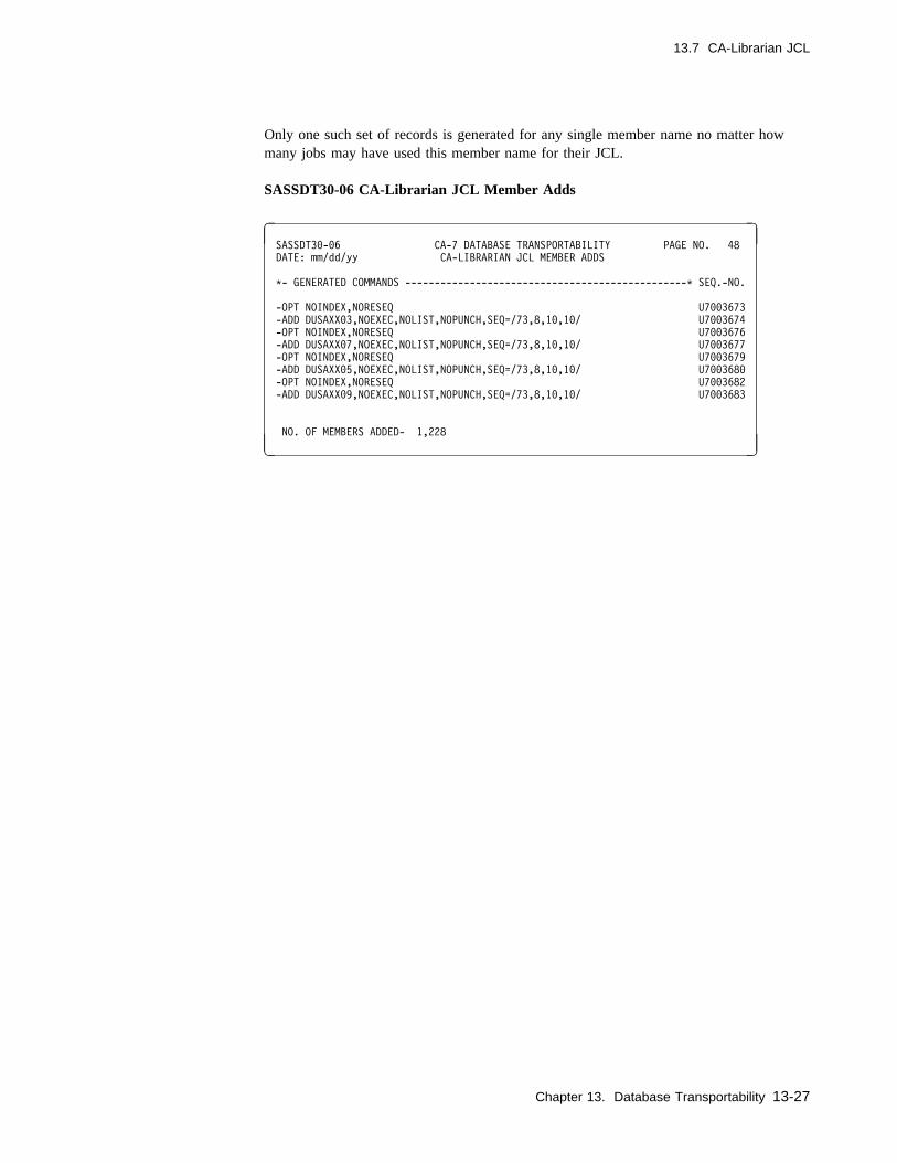
13.7 CA-Librarian JCL
Only one such set of records is generated for any single member name no matter howmany jobs may have used this member name for their JCL.
SASSDT30-06 CA-Librarian JCL Member Adds
� �SASSDT3�-�6 CA-7 DATABASE TRANSPORTABILITY PAGE NO. 48
DATE: mm/dd/yy CA-LIBRARIAN JCL MEMBER ADDS
C- GENERATED COMMANDS ------------------------------------------------C SEQ.-NO.
-OPT NOINDEX,NORESEQ U7��3673
-ADD DUSAXX�3,NOEXEC,NOLIST,NOPUNCH,SEQ=/73,8,1�,1�/ U7��3674
-OPT NOINDEX,NORESEQ U7��3676
-ADD DUSAXX�7,NOEXEC,NOLIST,NOPUNCH,SEQ=/73,8,1�,1�/ U7��3677
-OPT NOINDEX,NORESEQ U7��3679
-ADD DUSAXX�5,NOEXEC,NOLIST,NOPUNCH,SEQ=/73,8,1�,1�/ U7��368�
-OPT NOINDEX,NORESEQ U7��3682
-ADD DUSAXX�9,NOEXEC,NOLIST,NOPUNCH,SEQ=/73,8,1�,1�/ U7��3683
NO. OF MEMBERS ADDED- 1,228
( )
Chapter 13. Database Transportability 13-27
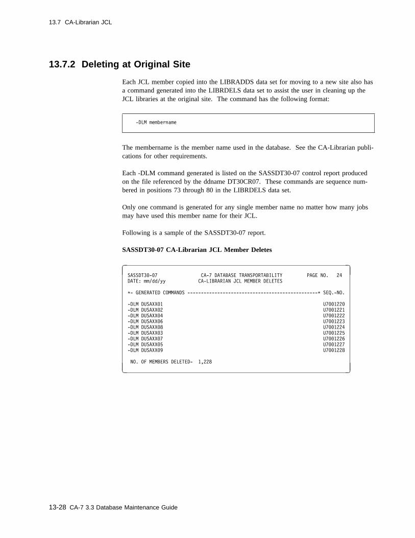
13.7 CA-Librarian JCL
13.7.2 Deleting at Original Site
Each JCL member copied into the LIBRADDS data set for moving to a new site also hasa command generated into the LIBRDELS data set to assist the user in cleaning up theJCL libraries at the original site. The command has the following format:
-DLM membername
The membername is the member name used in the database. See the CA-Librarian publi-cations for other requirements.
Each -DLM command generated is listed on the SASSDT30-07 control report producedon the file referenced by the ddname DT30CR07. These commands are sequence num-bered in positions 73 through 80 in the LIBRDELS data set.
Only one command is generated for any single member name no matter how many jobsmay have used this member name for their JCL.
Following is a sample of the SASSDT30-07 report.
SASSDT30-07 CA-Librarian JCL Member Deletes
� �SASSDT3�-�7 CA-7 DATABASE TRANSPORTABILITY PAGE NO. 24
DATE: mm/dd/yy CA-LIBRARIAN JCL MEMBER DELETES
C- GENERATED COMMANDS ------------------------------------------------C SEQ.-NO.
-DLM DUSAXX�1 U7��122�
-DLM DUSAXX�2 U7��1221
-DLM DUSAXX�4 U7��1222
-DLM DUSAXX�6 U7��1223
-DLM DUSAXX�8 U7��1224
-DLM DUSAXX�3 U7��1225
-DLM DUSAXX�7 U7��1226
-DLM DUSAXX�5 U7��1227
-DLM DUSAXX�9 U7��1228
NO. OF MEMBERS DELETED- 1,228
( )
13-28 CA-7 3.3 Database Maintenance Guide
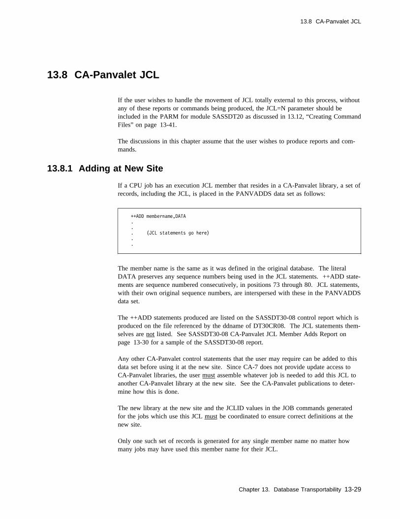
13.8 CA-Panvalet JCL
13.8 CA-Panvalet JCL
If the user wishes to handle the movement of JCL totally external to this process, withoutany of these reports or commands being produced, the JCL=N parameter should beincluded in the PARM for module SASSDT20 as discussed in 13.12, “Creating CommandFiles” on page 13-41.
The discussions in this chapter assume that the user wishes to produce reports and com-mands.
13.8.1 Adding at New Site
If a CPU job has an execution JCL member that resides in a CA-Panvalet library, a set ofrecords, including the JCL, is placed in the PANVADDS data set as follows:
++ADD membername,DATA
.
.
. (JCL statements go here)
.
.
The member name is the same as it was defined in the original database. The literalDATA preserves any sequence numbers being used in the JCL statements. ++ADD state-ments are sequence numbered consecutively, in positions 73 through 80. JCL statements,with their own original sequence numbers, are interspersed with these in the PANVADDSdata set.
The ++ADD statements produced are listed on the SASSDT30-08 control report which isproduced on the file referenced by the ddname of DT30CR08. The JCL statements them-selves are not listed. See SASSDT30-08 CA-Panvalet JCL Member Adds Report onpage 13-30 for a sample of the SASSDT30-08 report.
Any other CA-Panvalet control statements that the user may require can be added to thisdata set before using it at the new site. Since CA-7 does not provide update access toCA-Panvalet libraries, the user must assemble whatever job is needed to add this JCL toanother CA-Panvalet library at the new site. See the CA-Panvalet publications to deter-mine how this is done.
The new library at the new site and the JCLID values in the JOB commands generatedfor the jobs which use this JCL must be coordinated to ensure correct definitions at thenew site.
Only one such set of records is generated for any single member name no matter howmany jobs may have used this member name for their JCL.
Chapter 13. Database Transportability 13-29

13.8 CA-Panvalet JCL
SASSDT30-08 CA-Panvalet JCL Member Adds
� �SASSDT3�-�8 CA-7 DATABASE TRANSPORTABILITY PAGE NO. 24
DATE: mm/dd/yy CA-PANVALET JCL MEMBER ADDS
C- GENERATED COMMANDS ------------------------------------------------C SEQ.-NO.
++ADD DUSAXX�1,DATA U7��122�
++ADD DUSAXX�2,DATA U7��1221
++ADD DUSAXX�4,DATA U7��1222
++ADD DUSAXX�6,DATA U7��1223
++ADD DUSAXX�8,DATA U7��1224
++ADD DUSAXX�3,DATA U7��1225
++ADD DUSAXX�7,DATA U7��1226
++ADD DUSAXX�5,DATA U7��1227
++ADD DUSAXX�9,DATA U7��1228
NO. OF MEMBERS ADDED- 1,228
( )
13-30 CA-7 3.3 Database Maintenance Guide
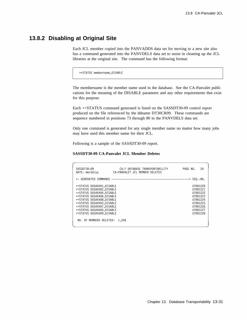
13.8 CA-Panvalet JCL
13.8.2 Disabling at Original Site
Each JCL member copied into the PANVADDS data set for moving to a new site alsohas a command generated into the PANVDELS data set to assist in cleaning up the JCLlibraries at the original site. The command has the following format:
++STATUS membername,DISABLE
The membername is the member name used in the database. See the CA-Panvalet publi-cations for the meaning of the DISABLE parameter and any other requirements that existfor this purpose.
Each ++STATUS command generated is listed on the SASSDT30-09 control reportproduced on the file referenced by the ddname DT30CR09. These commands aresequence numbered in positions 73 through 80 in the PANVDELS data set.
Only one command is generated for any single member name no matter how many jobsmay have used this member name for their JCL.
Following is a sample of the SASSDT30-09 report.
SASSDT30-09 CA-Panvalet JCL Member Deletes
� �SASSDT3�-�9 CA-7 DATABASE TRANSPORTABILITY PAGE NO. 24
DATE: mm/dd/yy CA-PANVALET JCL MEMBER DELETES
C- GENERATED COMMANDS ------------------------------------------------C SEQ.-NO.
++STATUS DUSAXX�1,DISABLE U7��122�
++STATUS DUSAXX�2,DISABLE U7��1221
++STATUS DUSAXX�4,DISABLE U7��1222
++STATUS DUSAXX�6,DISABLE U7��1223
++STATUS DUSAXX�8,DISABLE U7��1224
++STATUS DUSAXX�3,DISABLE U7��1225
++STATUS DUSAXX�7,DISABLE U7��1226
++STATUS DUSAXX�5,DISABLE U7��1227
++STATUS DUSAXX�9,DISABLE U7��1228
NO. OF MEMBERS DELETED- 1,228
( )
Chapter 13. Database Transportability 13-31
13.9 Cataloged Procedures
13.9 Cataloged Procedures
If the user wishes to handle the movement of JCL totally external to this process, withoutany of these reports or commands being produced, the JCL=N parameter should beincluded in the PARM for module SASSDT20 as discussed in 13.12, “Creating CommandFiles” on page 13-41.
The discussions in this chapter assume that the user wishes to produce reports and com-mands.
13.9.1 Adding at New Site
Normally, PROCLIBs are not made available to CA-7 since the processing of the pro-duction workload can be done without any such direct access. Therefore, this processmakes no attempt to gain access to PROCLIBs. Movement of any cataloged proceduresthat may be required at the new site must be taken care of by the user by some othermeans.
See the following discussion of deleting PROCs at the original site for a hardcopy reportthat can be of assistance in identifying what cataloged procedures need to be moved. Ifnothing else, that report can be used as a checklist for the member names that need to bemoved. If an entire library is being moved, this level of detail is not as important to theuser.
13-32 CA-7 3.3 Database Maintenance Guide
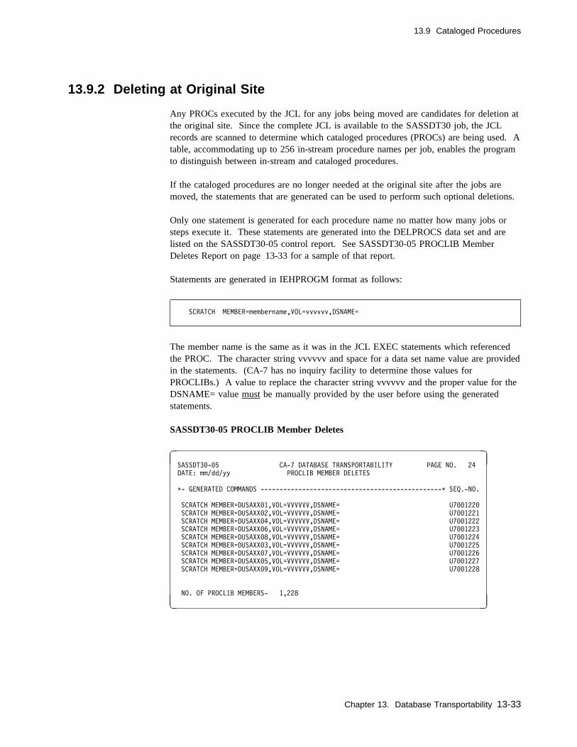
13.9 Cataloged Procedures
13.9.2 Deleting at Original Site
Any PROCs executed by the JCL for any jobs being moved are candidates for deletion atthe original site. Since the complete JCL is available to the SASSDT30 job, the JCLrecords are scanned to determine which cataloged procedures (PROCs) are being used. Atable, accommodating up to 256 in-stream procedure names per job, enables the programto distinguish between in-stream and cataloged procedures.
If the cataloged procedures are no longer needed at the original site after the jobs aremoved, the statements that are generated can be used to perform such optional deletions.
Only one statement is generated for each procedure name no matter how many jobs orsteps execute it. These statements are generated into the DELPROCS data set and arelisted on the SASSDT30-05 control report. See SASSDT30-05 PROCLIB MemberDeletes Report on page 13-33 for a sample of that report.
Statements are generated in IEHPROGM format as follows:
SCRATCH MEMBER=membername,VOL=vvvvvv,DSNAME=
The member name is the same as it was in the JCL EXEC statements which referencedthe PROC. The character string vvvvvv and space for a data set name value are providedin the statements. (CA-7 has no inquiry facility to determine those values forPROCLIBs.) A value to replace the character string vvvvvv and the proper value for theDSNAME= value must be manually provided by the user before using the generatedstatements.
SASSDT30-05 PROCLIB Member Deletes
� �SASSDT3�-�5 CA-7 DATABASE TRANSPORTABILITY PAGE NO. 24
DATE: mm/dd/yy PROCLIB MEMBER DELETES
C- GENERATED COMMANDS ------------------------------------------------C SEQ.-NO.
SCRATCH MEMBER=DUSAXX�1,VOL=VVVVVV,DSNAME= U7��122�
SCRATCH MEMBER=DUSAXX�2,VOL=VVVVVV,DSNAME= U7��1221
SCRATCH MEMBER=DUSAXX�4,VOL=VVVVVV,DSNAME= U7��1222
SCRATCH MEMBER=DUSAXX�6,VOL=VVVVVV,DSNAME= U7��1223
SCRATCH MEMBER=DUSAXX�8,VOL=VVVVVV,DSNAME= U7��1224
SCRATCH MEMBER=DUSAXX�3,VOL=VVVVVV,DSNAME= U7��1225
SCRATCH MEMBER=DUSAXX�7,VOL=VVVVVV,DSNAME= U7��1226
SCRATCH MEMBER=DUSAXX�5,VOL=VVVVVV,DSNAME= U7��1227
SCRATCH MEMBER=DUSAXX�9,VOL=VVVVVV,DSNAME= U7��1228
NO. OF PROCLIB MEMBERS- 1,228
( )
Chapter 13. Database Transportability 13-33
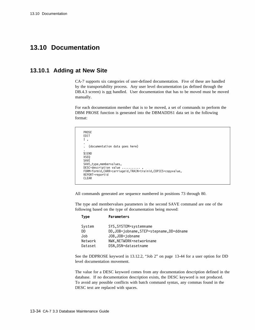
13.10 Documentation
13.10 Documentation
13.10.1 Adding at New Site
CA-7 supports six categories of user-defined documentation. Five of these are handledby the transportability process. Any user level documentation (as defined through theDB.4.3 screen) is not handled. User documentation that has to be moved must be movedmanually.
For each documentation member that is to be moved, a set of commands to perform theDBM PROSE function is generated into the DBMADDS1 data set in the followingformat:
PROSE
EDIT
I ,
.
. (documentation data goes here)
.
$IEND
XSEQ
SAVE
SAVE,type,membervalues,
DESC=description value ........... ,
FORM=formid,CARR=carriageid,TRAIN=trainid,COPIES=copyvalue,
REPORT=reportid
CLEAR
All commands generated are sequence numbered in positions 73 through 80.
The type and membervalues parameters in the second SAVE command are one of thefollowing based on the type of documentation being moved:
Type Parameters
System SYS,SYSTEM=systemname
DD DD,JOB=jobname,STEP=stepname,DD=ddname
Job JOB,JOB=jobname
Network NWK,NETWORK=networkname
Dataset DSN,DSN=datasetname
See the DDPROSE keyword in 13.12.2, “Job 2” on page 13-44 for a user option for DDlevel documentation movement.
The value for a DESC keyword comes from any documentation description defined in thedatabase. If no documentation description exists, the DESC keyword is not produced.To avoid any possible conflicts with batch command syntax, any commas found in theDESC text are replaced with spaces.
13-34 CA-7 3.3 Database Maintenance Guide
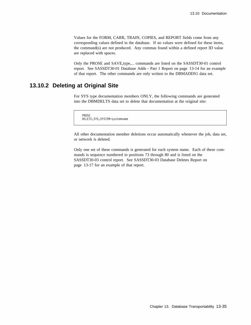
13.10 Documentation
Values for the FORM, CARR, TRAIN, COPIES, and REPORT fields come from anycorresponding values defined in the database. If no values were defined for these items,the command(s) are not produced. Any commas found within a defined report ID valueare replaced with spaces.
Only the PROSE and SAVE,type,... commands are listed on the SASSDT30-01 controlreport. See SASSDT30-01 Database Adds - Part 1 Report on page 13-14 for an exampleof that report. The other commands are only written to the DBMADDS1 data set.
13.10.2 Deleting at Original Site
For SYS type documentation members ONLY, the following commands are generatedinto the DBMDELTS data set to delete that documentation at the original site:
PROSE
DELETE,SYS,SYSTEM=systemname
All other documentation member deletions occur automatically whenever the job, data set,or network is deleted.
Only one set of these commands is generated for each system name. Each of these com-mands is sequence numbered in positions 73 through 80 and is listed on theSASSDT30-03 control report. See SASSDT30-03 Database Deletes Report onpage 13-17 for an example of that report.
Chapter 13. Database Transportability 13-35

13.11 Schedules
13.11 Schedules
13.11.1 Adding at New Site
13.11.1.1 CPU Job Schedules
For defined schedule IDs for those CPU jobs being moved, a set of commands to performthe necessary DBM SCHD,JOB function is generated into the DBMADDS2 data set asfollows:
SCHD
JOB
EDIT
ADD,SCHID=nnn,ROLL=x,INDEX=>nnn,TIME=(dotm,ldtm,sbtm),
frequency values, etc. ...
.
.
SAVE
SAVE,JOB=jobname,SCAL=yy
DBM
RESOLV,SCAL=yy,TEST=NO,JOB=jobname
See Chapter 3, “Scheduling” for more information on these commands.
All of the values used here are as they were defined in the database including the BaseCalendar ID. If the same Base Calendar names are not being used at the new site, thesehave to be manually edited by the user to the correct value.
Whenever there are multiple schedule IDs to be added for a single job, the ADD,...sequence is repeated as necessary, between the EDIT and SAVE commands, to define allthose schedules at one time.
These commands are sequence numbered in positions 73 through 80 and listed on theSASSDT30-02 control report. See SSASSDT30-02 Database Adds - Part 2 Report onpage 13-16 for an example of that report.
If the job had a current schedule modification, made with the online DB.2.7 screen func-tion, a message to that effect is appended to the end of the listed records on reportSASSDT30-02. Any such changes have to be investigated and reapplied manually at thenew site after this schedule is defined in that database.
13-36 CA-7 3.3 Database Maintenance Guide
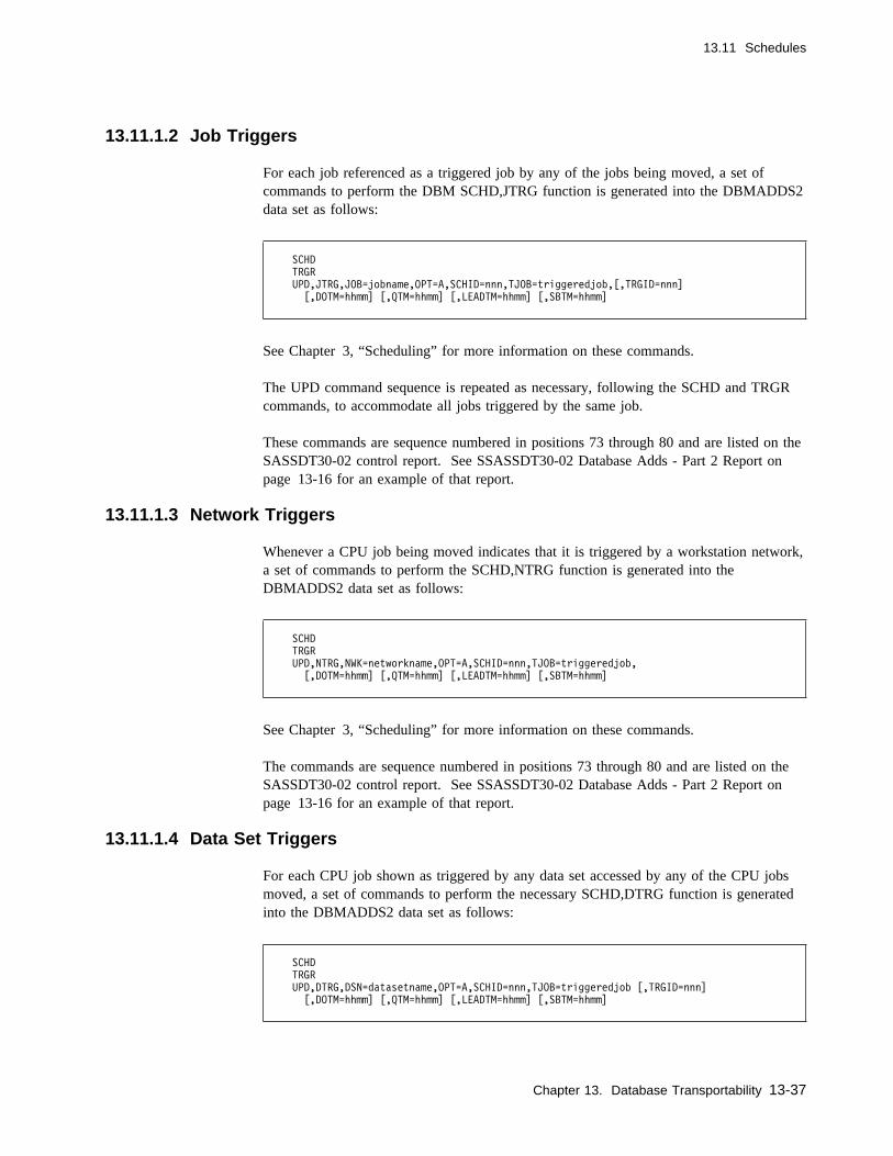
13.11 Schedules
13.11.1.2 Job Triggers
For each job referenced as a triggered job by any of the jobs being moved, a set ofcommands to perform the DBM SCHD,JTRG function is generated into the DBMADDS2data set as follows:
SCHD
TRGR
UPD,JTRG,JOB=jobname,OPT=A,SCHID=nnn,TJOB=triggeredjob,[,TRGID=nnn]
[,DOTM=hhmm] [,QTM=hhmm] [,LEADTM=hhmm] [,SBTM=hhmm]
See Chapter 3, “Scheduling” for more information on these commands.
The UPD command sequence is repeated as necessary, following the SCHD and TRGRcommands, to accommodate all jobs triggered by the same job.
These commands are sequence numbered in positions 73 through 80 and are listed on theSASSDT30-02 control report. See SSASSDT30-02 Database Adds - Part 2 Report onpage 13-16 for an example of that report.
13.11.1.3 Network Triggers
Whenever a CPU job being moved indicates that it is triggered by a workstation network,a set of commands to perform the SCHD,NTRG function is generated into theDBMADDS2 data set as follows:
SCHD
TRGR
UPD,NTRG,NWK=networkname,OPT=A,SCHID=nnn,TJOB=triggeredjob,
[,DOTM=hhmm] [,QTM=hhmm] [,LEADTM=hhmm] [,SBTM=hhmm]
See Chapter 3, “Scheduling” for more information on these commands.
The commands are sequence numbered in positions 73 through 80 and are listed on theSASSDT30-02 control report. See SSASSDT30-02 Database Adds - Part 2 Report onpage 13-16 for an example of that report.
13.11.1.4 Data Set Triggers
For each CPU job shown as triggered by any data set accessed by any of the CPU jobsmoved, a set of commands to perform the necessary SCHD,DTRG function is generatedinto the DBMADDS2 data set as follows:
SCHD
TRGR
UPD,DTRG,DSN=datasetname,OPT=A,SCHID=nnn,TJOB=triggeredjob [,TRGID=nnn]
[,DOTM=hhmm] [,QTM=hhmm] [,LEADTM=hhmm] [,SBTM=hhmm]
Chapter 13. Database Transportability 13-37

13.11 Schedules
See Chapter 3, “Scheduling” for more information on these commands.
Since this process only moves jobs that are either explicitly requested or required bythose jobs and within one level of those requested, this could produce commands thattrigger some jobs that were not intended to be moved and may not have a job definitiongenerated by this process. To prevent unsuccessful updates, the user has to verify theaccuracy of this before trying to use the generated commands at the new site.
These commands are sequence numbered in positions 73 through 80 and are listed on theSASSDT30-02 control report. See SSASSDT30-02 Database Adds - Part 2 Report onpage 13-16 for an example of that report.
13.11.1.5 Input Networks
For each input workstation network being moved to the new site, each schedule IDdefined has a set of commands generated into the DBMADDS2 data set to perform theSCHD,INWK and RESOLV functions. These commands are in the following format:
SCHD
INWK
EDIT,NETWORK=networkname
ADD,SCHID=nnn,TIME=(dotm1,ldtm1,dody1,dotm2,...),
frequency values, etc. ...
.
.
SAVE
SAVE,NETWORK=networkname,SCAL=cc,ROLL=x,INDEX=>nnn
DBM
RESOLV,SCAL=cc,TEST=NO,NW=NW.networkname
See Chapter 3, “Scheduling” for more information on these commands. Also see13.11.1.1, “CPU Job Schedules” on page 13-36 for a discussion of the DB.2.7 warningmessage which may appear on the control report following these records for workstationnetworks.
The ADD commands are repeated as many times as necessary between the EDIT andSAVE commands to accommodate all of the schedule IDs to be defined. All parametervalues used are as they were defined in the original database including the Base CalendarID which the schedule references. If the Base Calendar ID at the new site is different,these commands have to be manually edited to the correct value before being used.
Input network triggers are added. However, the TRGID value is not carried forward tothe receiving site.
Each command is sequence numbered in positions 73 through 80 and is listed on theSASSDT30-02 control report. See SSASSDT30-02 Database Adds - Part 2 Report onpage 13-16 for an example of that report.
13-38 CA-7 3.3 Database Maintenance Guide
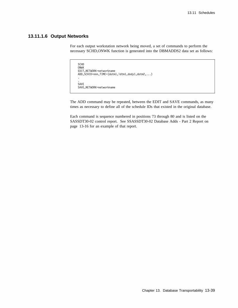
13.11 Schedules
13.11.1.6 Output Networks
For each output workstation network being moved, a set of commands to perform thenecessary SCHD,ONWK function is generated into the DBMADDS2 data set as follows:
SCHD
ONWK
EDIT,NETWORK=networkname
ADD,SCHID=nnn,TIME=(dotm1,ldtm1,dody1,dotm2,...)
.
.
SAVE
SAVE,NETWORK=networkname
The ADD command may be repeated, between the EDIT and SAVE commands, as manytimes as necessary to define all of the schedule IDs that existed in the original database.
Each command is sequence numbered in positions 73 through 80 and is listed on theSASSDT30-02 control report. See SSASSDT30-02 Database Adds - Part 2 Report onpage 13-16 for an example of that report.
Chapter 13. Database Transportability 13-39
13.11 Schedules
13.11.2 Deleting at Original Site
13.11.2.1 CPU Job Schedules
Since the schedules for CPU jobs are automatically deleted whenever the job definition isdeleted from the database, no additional commands are generated by this process to deleteCPU job schedules.
See 13.3.4, “Disabling at Original Site” on page 13-18 for related commands to disablejobs.
13.11.2.2 Input Network Schedules
Since the schedules for input workstation networks are automatically deleted wheneverthe network definition is deleted from the database, no additional commands are neededto delete them.
13.11.2.3 Output Network Schedules
Since output networks are scheduled whenever their associated CPU job is scheduled, noextra commands are necessary. See 13.11.1.1, “CPU Job Schedules” on page 13-36 formore information on these schedules.
13-40 CA-7 3.3 Database Maintenance Guide
13.12 Creating Command Files
13.12 Creating Command Files
The transportability process consists of multiple steps. It could be done with a single job.The user probably wishes to develop multiple jobs, however, so that the processing canbe manually verified between each of the three major iterations against the database.
The following discussions and examples assume that the user uses three different jobs toperform this process. JCL parameters which require special consideration are indicated inlowercase notation in the JCL examples. Unless unusually large numbers of jobs, quanti-ties of documentation, and numbers of networks are being moved, the space allocations inthe examples should be sufficient.
Before running any of the jobs, be sure to set the NLINE value in the TERM statementfor the batch terminal being used to the maximum value. This minimizes the number ofheadings (and DASD space) required during the iterations of this process. See the CA-7Systems Programmer Guide for a discussion of this initialization file parameter.
A discussion of the design limitations of this process is in 13.13, “SpecialConsiderations” on page 13-50.
13.12.1 Job 1
The first two steps of this job are standard BTI steps. See "Using Batch Terminals" inthe CA-7 Interfaces Guide for more information on these steps.
13.12.1.1 PARM Keywords
A CA-7 operator ID should be provided in the PARM data in the last step. A passwordcan also be given. The format of the value for LOGON= is the same as it is for the/LOGON command to CA-7, including the comma which separates the operator ID andany password value being provided. Operator ID can be up to 8 characters in length. Amaximum total of 65 characters is allowed for the operator ID, the password value andthe comma which separates them. Any characters following the operator ID, and until avalid keyword (or end of PARM) is found, are assumed to be password data.
The LOGON keyword is optional. The default operator ID is MASTER in the generated/LOGON command and the command does not have a password value in it. If LOGON=is entered with no data following the equal sign, the /LOGON command is generatedwithout an operator ID or a password.
If no LOGON value is provided or defaulted, the operator ID, and optionally the pass-word field, has to be provided manually, in the DT10OUT data set, before that outputdata set can be processed by BTI (for SASSDT20).
Chapter 13. Database Transportability 13-41

13.12 Creating Command Files
13.12.1.2 Specifying Jobs to Move
The input to the BTI run is in the form of CA-7 LJOB and/or LSYS commands. Theymay be used in any combination to define the jobs to be moved. If there are any work-station networks to also be moved, the programs automatically include those with a pred-ecessor or successor relationship with any of the jobs specified. If there are others notconnected to a job, they must be moved manually by the user following the examplesgiven in 13.4, “Workstation Networks” on page 13-19.
Requirements for /LOGON and /LOGOFF commands are the same here as for any BTIdata set and must be supplied in addition to any LJOB or LSYS commands.
If the LSYS command is used, every job in the database with the same system name asthat indicated has commands generated to define the job(s) into another database. Thisassumes that the optional system name was entered for each of the desired jobs whenthey were defined in the database. It may be safer to use the LJOB command with ageneric job name since job names are required in the database. Job naming conventionsusually make generic specification of the desired names relatively easy. Multiple com-mands can be used as necessary to define all of the desired jobs.
Jobs which have any type of predecessor or trigger relationship with any of the jobsbeing moved are also included in the final output command data sets produced by thisprocess. That is made possible by the look-aside process which enables automatic inclu-sion of workstation networks. This look-aside process only looks one level in each direc-tion from a job that was requested to be moved.
13-42 CA-7 3.3 Database Maintenance Guide

13.12 Creating Command Files
13.12.1.3 Data Sets Used/Created
The SYSPRINT output is being passed to the third step as that step's input.
The third step examines the output from the BTI step and generates another card-imageBTI data set through ddname DT10OUT. This data set is the input to Job 2. TheSASSDT10-01 control report, which can be of assistance in determining if this step rancorrectly, is produced through the ddname DT10CR01. See SASSDT10-01 JobsRequested to be Moved Report on page 13-8 for an example of that report.
//jobname JOB ........,REGION=1�24K
//EXTRACT EXEC PGM=SASSBSTR,PARM=batch-terminal-id
//JOBLIB DD DSN=ca7.loadlib,DISP=SHR
//UCC7CMDS DD DSN=ca7.communications.data.set,DISP=SHR
//BATCHIN DD DSN=batch.input.data.set,DISP=SHR
//BATCHOUT DD DSN=batch.output.data.set,DISP=SHR
//SYSOUT DD SYSOUT=x
//SYSPRINT DD DSN=&&DT1�IN,DISP=(,PASS),UNIT=SYSDA,
// SPACE=(CYL,(5,1),RLSE),DCB=(RECFM=FBA,LRECL=133,BLKSIZE=399�)
//SYSIN DD C
/LOGON operid[,password]
LJOB,JOB=jobname
LSYS,SYS=systemname
/LOGOFF
//C
//stepname EXEC PGM=SASSDT1�,COND=(�,NE,EXTRACT),
// PARM='LOGON=operid[,password]'
//DT1�IN DD DSN=&&DT1�IN,DISP=(OLD,DELETE)
//DT1�OUT DD DSN=input.to.job2,DISP=(,CATLG),
// UNIT=SYSDA,SPACE=(CYL,(2,1),RLSE),
// DCB=(RECFM=FB,LRECL=8�,BLKSIZE=4���)
//DT1�CR�1 DD SYSOUT=x,DCB=BLKSIZE=133
//SYSUDUMP DD SYSOUT=x
Figure 13-1. SASSDT10 Execution JCL
Chapter 13. Database Transportability 13-43
13.12 Creating Command Files
13.12.2 Job 2
After verifying that the jobs were identified correctly in Job 1, Job 2 may be run.
This job performs another iteration against the database much like the first job. Com-mands in the SYSIN data set for SASSBSTR cause listings to be produced for JCL,trigger, and requirement information for each of the jobs to be moved. ModuleSASSDT20 examines the BTI output (ddname DT20IN) and produces another card-imagedata set to be used in Job 3 (ddname DT20OUT).
13.12.2.1 PARM Keywords
A LOGON value should be provided in the PARM data for SASSDT20. This PARMvalue has the same format and meaning as discussed for SASSDT10 in 13.12.1, “Job 1”on page 13-41.
The user also has an option available which can significantly reduce the DASD require-ments and slightly reduce the runtime. If the user does not use DD level documentation,as defined with the PROSE,DD online screen, DDPROSE=N should be specified in thePARM data. N is the only acceptable value.
Without this specification, the program produces an LPROS command for each nonblankstepname/ddname combination just to determine if any DD level documentation exists.Such unnecessary commands can represent as much as 85 percent or more of the numberof commands needed to accomplish any one move. (Since it takes very little time foreach of these commands to execute, the elapsed time savings are negligible compared tothe DASD savings.) If the extra DASD space and runtime are of no particular concern,DDPROSE=N should not be specified. This ensures that any such existing documenta-tion is included in the data being moved.
The user also has the option to totally ignore the movement of any JCL. This is accom-plished by coding the parameter JCL=N in the PARM data for module SASSDT20. N isthe only acceptable value. With this option specified, JCL is ignored here and the usermust handle the movement of the JCL totally external to this process. JCL=N in this jobsuppresses all of the JCL related reports and command data sets in Job 3 as well. It maybe wise to run these three jobs once without this option just to get the reports and againlater with this option if necessary.
13.12.2.2 Data Sets Used/Created
DT20WORK is a work file used by SASSDT20. It must not have a DISP of MOD.
DATASETS contains one card-image record for each application data set name beingmoved with the name beginning in position 1 of the record. (This data set may be usefulfor producing sorted data set checklists to assist in the physical movement of data sets tothe new site.)
13-44 CA-7 3.3 Database Maintenance Guide
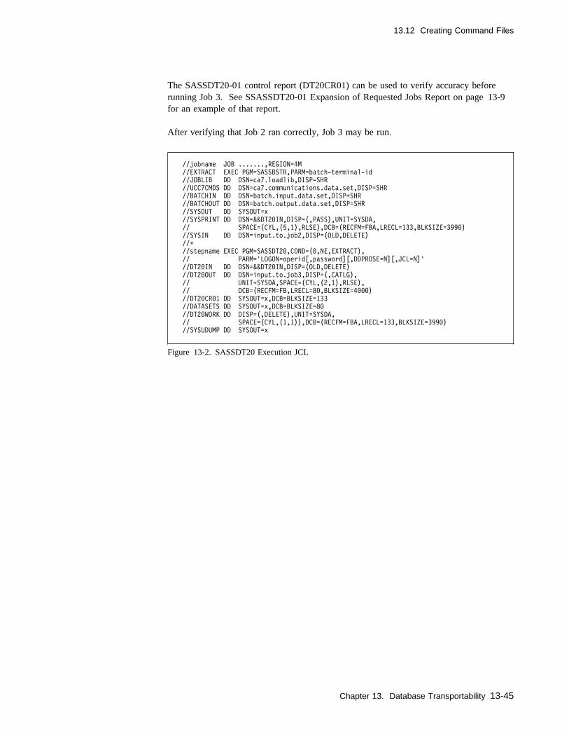
13.12 Creating Command Files
The SASSDT20-01 control report (DT20CR01) can be used to verify accuracy beforerunning Job 3. See SSASSDT20-01 Expansion of Requested Jobs Report on page 13-9for an example of that report.
After verifying that Job 2 ran correctly, Job 3 may be run.
//jobname JOB .......,REGION=4M
//EXTRACT EXEC PGM=SASSBSTR,PARM=batch-terminal-id
//JOBLIB DD DSN=ca7.loadlib,DISP=SHR
//UCC7CMDS DD DSN=ca7.communications.data.set,DISP=SHR
//BATCHIN DD DSN=batch.input.data.set,DISP=SHR
//BATCHOUT DD DSN=batch.output.data.set,DISP=SHR
//SYSOUT DD SYSOUT=x
//SYSPRINT DD DSN=&&DT2�IN,DISP=(,PASS),UNIT=SYSDA,
// SPACE=(CYL,(5,1),RLSE),DCB=(RECFM=FBA,LRECL=133,BLKSIZE=399�)
//SYSIN DD DSN=input.to.job2,DISP=(OLD,DELETE)
//C
//stepname EXEC PGM=SASSDT2�,COND=(�,NE,EXTRACT),
// PARM='LOGON=operid[,password][,DDPROSE=N][,JCL=N]'
//DT2�IN DD DSN=&&DT2�IN,DISP=(OLD,DELETE)
//DT2�OUT DD DSN=input.to.job3,DISP=(,CATLG),
// UNIT=SYSDA,SPACE=(CYL,(2,1),RLSE),
// DCB=(RECFM=FB,LRECL=8�,BLKSIZE=4���)
//DT2�CR�1 DD SYSOUT=x,DCB=BLKSIZE=133
//DATASETS DD SYSOUT=x,DCB=BLKSIZE=8�
//DT2�WORK DD DISP=(,DELETE),UNIT=SYSDA,
// SPACE=(CYL,(1,1)),DCB=(RECFM=FBA,LRECL=133,BLKSIZE=399�)
//SYSUDUMP DD SYSOUT=x
Figure 13-2. SASSDT20 Execution JCL
Chapter 13. Database Transportability 13-45

13.12 Creating Command Files
13.12.3 Job 3
This job performs another iteration against the database, much like the first two jobs.Commands in the SYSIN data set, from Job 2, cause listings to be produced for otherdatabase elements that are to be moved. The user may also have manually included someLNTWK and LPROS commands to include some workstation networks that did not havean explicit connection to any of the jobs being moved. SASSDT30 examines the BTIoutput (DBMLISTS) and creates several command data sets.
13.12.3.1 PARM Keywords
A LOGON value should be provided in the PARM data for SASSDT30. This keywordvalue has the same format and meaning as that discussed for SASSDT10 in 13.12.1, “Job1” on page 13-41.
The user also has the following optional keywords which can be provided in the PARMfor the purposes indicated:
JOBDD=YIndicates to generate JOB deletes with the function value of DD instead of DELETEso that dormant data sets can be deleted when the job is deleted. DD commandsrequire more execution time than DELETE commands whenever they are processedagainst the database to do the actual deletes. This time could be significant if a largenumber of commands are processed at once. See the discussion of the 2.2, “DB.1 -CPU Job Definition Screen” on page 2-3 for details of this function. Y is the onlyacceptable value.
AFTER=yyddd[hhmm]Indicates "don't schedule after" values to use for the disable commands generated todisable CPU jobs at the original site. If not provided, the current system date andtime are used for this purpose. If only the Julian date is provided, the default time-of-day is zeros (for the morning of the date entered). See the discussion of the 2.2,“DB.1 - CPU Job Definition Screen” on page 2-3 for details of this function.
BEFORE=yyddd[hhmm]Indicates "don't schedule before" values to use for the add commands generated toadd CPU jobs at the new site. If not provided, no value is generated and the work iseligible to run at the new site as soon as it is completely defined in that database. Ifonly the Julian date is provided, the default time-of-day is zeros (for the morning ofthe date entered). See the discussion of the 2.2, “DB.1 - CPU Job Definition Screen”on page 2-3 for details of this function.
LOADS=YIndicates that LOAD commands are to be generated for each CPU job. When speci-fied, LOAD commands are generated into the DBMADDS2 data set after the JCLhas been processed for the job. This parameter cannot be used if JCL=N was speci-fied in Job 2 since that specification prevents any JCL from appearing in the input tothis job. (If necessary, multiple executions of this process could be run to create thedesired command data sets.) Y is the only acceptable value.
13-46 CA-7 3.3 Database Maintenance Guide
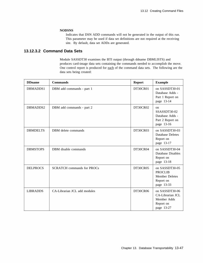
13.12 Creating Command Files
NODSNSIndicates that DSN ADD commands will not be generated in the output of this run.This parameter may be used if data set definitions are not required at the receivingsite. By default, data set ADDs are generated.
13.12.3.2 Command Data Sets
Module SASSDT30 examines the BTI output (through ddname DBMLISTS) andproduces card-image data sets containing the commands needed to accomplish the move.One control report is produced for each of the command data sets. The following are thedata sets being created:
DDname Commands Report Example
DBMADDS1 DBM add commands - part 1 DT30CR01 on SASSDT30-01Database Adds -Part 1 Report onpage 13-14
DBMADDS2 DBM add commands - part 2 DT30CR02 onSSASSDT30-02Database Adds -Part 2 Report onpage 13-16
DBMDELTS DBM delete commands DT30CR03 on SASSDT30-03Database DeletesReport onpage 13-17
DBMSTOPS DBM disable commands DT30CR04 on SASSDT30-04Database DisablesReport onpage 13-18
DELPROCS SCRATCH commands for PROCs DT30CR05 on SASSDT30-05PROCLIBMember DeletesReport onpage 13-33
LIBRADDS CA-Librarian JCL add modules DT30CR06 on SASSDT30-06CA-Librarian JCLMember AddsReport onpage 13-27
Chapter 13. Database Transportability 13-47

13.12 Creating Command Files
DDname Commands Report Example
LIBRDELS CA-Librarian delete commands DT30CR07 on SASSDT30-07CA-Librarian JCLMember DeletesReport onpage 13-28
PANVADDS CA-Panvalet JCL add modules DT30CR08 on SASSDT30-08CA-Panvalet JCLMember AddsReport onpage 13-30
PANVDELS CA-Panvalet disable commands DT30CR09 on SASSDT30-09CA-Panvalet JCLMember DeletesReport onpage 13-31
Details on the contents of these data sets and the examples of these control reports weregiven in the discussions on 13.3, “CPU Jobs” on page 13-13, and 13.4, “WorkstationNetworks” on page 13-19, and so forth.
It is very likely that some of these data sets require some manual editing and changingbefore they can be used. For example, changing JCLID numbers must be taken care ofby editing these data sets. For other considerations, see 13.1, “Assumptions” onpage 13-3 and 13.13.3, “Running at New Site” on page 13-51. The control reportsclosely mirror the contents of the data sets, including the generated sequence numbers.This makes it easier to locate specific commands requiring changes.
13-48 CA-7 3.3 Database Maintenance Guide
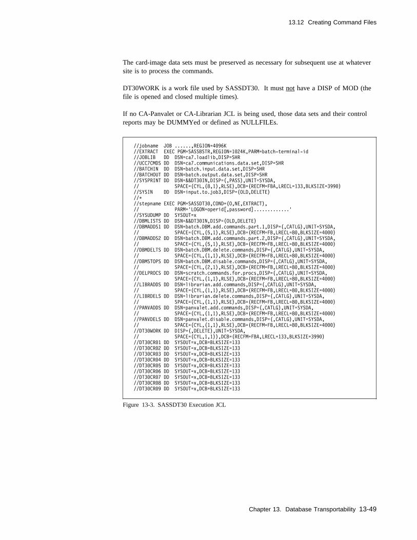
13.12 Creating Command Files
The card-image data sets must be preserved as necessary for subsequent use at whateversite is to process the commands.
DT30WORK is a work file used by SASSDT30. It must not have a DISP of MOD (thefile is opened and closed multiple times).
If no CA-Panvalet or CA-Librarian JCL is being used, those data sets and their controlreports may be DUMMYed or defined as NULLFILEs.
//jobname JOB ......,REGION=4�96K
//EXTRACT EXEC PGM=SASSBSTR,REGION=1�24K,PARM=batch-terminal-id
//JOBLIB DD DSN=ca7.loadlib,DISP=SHR
//UCC7CMDS DD DSN=ca7.communications.data.set,DISP=SHR
//BATCHIN DD DSN=batch.input.data.set,DISP=SHR
//BATCHOUT DD DSN=batch.output.data.set,DISP=SHR
//SYSPRINT DD DSN=&&DT3�IN,DISP=(,PASS),UNIT=SYSDA,
// SPACE=(CYL,(8,1),RLSE),DCB=(RECFM=FBA,LRECL=133,BLKSIZE=399�)
//SYSIN DD DSN=input.to.job3,DISP=(OLD,DELETE)
//C
//stepname EXEC PGM=SASSDT3�,COND=(O,NE,EXTRACT),
// PARM='LOGON=operid[,password].............'
//SYSUDUMP DD SYSOUT=x
//DBMLISTS DD DSN=&&DT3�IN,DISP=(OLD,DELETE)
//DBMADDS1 DD DSN=batch.DBM.add.commands.part.1,DISP=(,CATLG),UNIT=SYSDA,
// SPACE=(CYL,(5,1),RLSE),DCB=(RECFM=FB,LRECL=8�,BLKSIZE=4���)
//DBMADDS2 DD DSN=batch.DBM.add.commands.part.2,DISP=(,CATLG),UNIT=SYSDA,
// SPACE=(CYL,(5,1),RLSE),DCB=(RECFM=FB,LRECL=8�,BLKSIZE=4���)
//DBMDELTS DD DSN=batch.DBM.delete.commands,DISP=(,CATLG),UNIT=SYSDA,
// SPACE=(CYL,(1,1),RLSE),DCB=(RECFM=FB,LRECL=8�,BLKSIZE=4���)
//DBMSTOPS DD DSN=batch.DBM.disable.commands,DISP=(,CATLG),UNIT=SYSDA,
// SPACE=(CYL,(2,1),RLSE),DCB=(RECFM=FB,LRECL=8�,BLKSIZE=4���)
//DELPROCS DD DSN=scratch.commands.for.procs,DISP=(,CATLG),UNIT=SYSDA,
// SPACE=(CYL,(1,1),RLSE),DCB=(RECFM=FB,LRECL=8�,BLKSIZE=4���)
//LIBRADDS DD DSN=librarian.add.commands,DISP=(,CATLG),UNIT=SYSDA,
// SPACE=(CYL,(1,1),RLSE),DCB=(RECFM=FB,LRECL=8�,BLKSIZE=4���)
//LIBRDELS DD DSN=librarian.delete.commands,DISP=(,CATLG),UNIT=SYSDA,
// SPACE=(CYL,(1,1),RLSE),DCB=(RECFM=FB,LRECL=8�,BLKSIZE=4���)
//PANVADDS DD DSN=panvalet.add.commands,DISP=(,CATLG),UNIT=SYSDA,
// SPACE=(CYL,(1,1),RLSE),DCB=(RECFM=FB,LRECL=8�,BLKSIZE=4���)
//PANVDELS DD DSN=panvalet.disable.commands,DISP=(,CATLG),UNIT=SYSDA,
// SPACE=(CYL,(1,1),RLSE),DCB=(RECFM=FB,LRECL=8�,BLKSIZE=4���)
//DT3�WORK DD DISP=(,DELETE),UNIT=SYSDA,
// SPACE=(CYL,1,1)),DCB=(RECFM=FBA,LRECL=133,BLKSIZE=399�)
//DT3�CR�1 DD SYSOUT=x,DCB=BLKSIZE=133
//DT3�CR�2 DD SYSOUT=x,DCB=BLKSIZE=133
//DT3�CR�3 DD SYSOUT=x,DCB=BLKSIZE=133
//DT3�CR�4 DD SYSOUT=x,DCB=BLKSIZE=133
//DT3�CR�5 DD SYSOUT=x,DCB=BLKSIZE=133
//DT3�CR�6 DD SYSOUT=x,DCB=BLKSIZE=133
//DT3�CR�7 DD SYSOUT=x,DCB=BLKSIZE=133
//DT3�CR�8 DD SYSOUT=x,DCB=BLKSIZE=133
//DT3�CR�9 DD SYSOUT=x,DCB=BLKSIZE=133
Figure 13-3. SASSDT30 Execution JCL
Chapter 13. Database Transportability 13-49

13.13 Special Considerations
13.13 Special Considerations
13.13.1 Design Limitations
The transportability process uses internal tables to keep from duplicating definition ofjobs, networks, and other items in the final output. These tables also ensure that aminimum of commands are issued during the intermediate steps of this process.
Each of the three modules executed in the three jobs which constitute this process usestables for these purposes as follows:
All but one of these limits apply to the entire workload definition being moved. The onlyexception is the limit of in-stream procedures, in SASSDT30, which is the maximumnumber within any one execution JCL member. (This table is used to distinguishbetween cataloged procedures and in-stream procedures.)
If any of these limitations are insufficient for any particular move, the user could:
� Break it up into multiples of this process by only requesting a number of jobs thatdoes not exceed these limits, or
� Make the coding changes to the programs for the appropriate values.
Module Maximum# Component
SASSDT10 50,000 CPU job names
SASSDT20 1,000 Application system names
SASSDT20 50,000 CPU job names
SASSDT20 10,000 Workstation network names
SASSDT20 300,000 CA-7 assigned data set numbers
SASSDT30 50,000 Execution JCL member names
SASSDT30 50,000 Cataloged procedure names
SASSDT30 256 In-stream procedures (maximum per job)
13-50 CA-7 3.3 Database Maintenance Guide

13.13 Special Considerations
13.13.2 Adding to the New Database
Once the appropriate command data sets have been physically taken to the new site, theDBM adds (parts 1 and 2) must be processed by CA-7 at that site. Any JCL libraries forCA-Panvalet or CA-Librarian JCL also must be processed at that site. Either a batchterminal job or a batch execution of CA-7 could be used to accomplish this. If using thebatch execution of CA-7, see the CA-7 Systems Programmer Guide Chapter 3, for batchexecution procedures.
Note: The DBMADDS1 and DBMADDS2 data sets must be processed in the correctsequence. If DBMADDS1 is not processed first, all of the commands inDBMADDS2 are rejected with error messages.
The user should review the amount of available space in the database at the new sitebefore attempting to add the new jobs. Comparing job counts and space allocations atboth sites, prior to performing this process, gives the user some idea of how much morespace, if any, is needed. This probably was already done when the initial plans werebeing made for the movement of the workload to the other center. See the CA-7 SystemsProgrammer Guide for guidelines for calculating space requirements in the database.
Depending on the number of jobs, documentation lines, and other items being moved, thevolume of output from DBM when the commands are processed at the new site could bevery large. Normal batch terminal allocations would probably not be large enough tohold all of this. Since documentation is added one record at a time, with a response backafter each line in batch, this alone can require a large allocation.
The output from the maintenance against the new database should be carefully reviewedfor accuracy of definitions. Duplicates become obvious at this point. Any duplication ofnames for jobs, networks, and other items have to be resolved manually by the user.
13.13.3 Running at New Site
The work is eligible to be scheduled at the new site as soon as the work and its schedulesare completely defined in the database. If any delay is desired, the commands for theCPU jobs can include the "don't schedule before" parameters, BDATE and BTIME, toaccomplish this for CPU jobs (not networks).
The user can provide this either by:
� Using the BEFORE keyword in the PARM for Job 3, or� Manually editing the desired values into the generated records prior to adding the
work to the database.
Chapter 13. Database Transportability 13-51
13.13 Special Considerations
13.13.4 Mass Changes at Existing Site
Even though the database transportability programs were developed to assist with thetransfer of work from one site to another, it can also be used to perform mass or globalchanges at an existing site.
To accomplish such changes the desired work is identified by LJOB and LSYS com-mands, as described in preceding chapters, and the three jobs are run as indicated. Thendesired changes are made to the command files (DBMADDS1 and DBMADDS2). Suchchanges could be renaming of jobs, systems, and data sets or just changing certain joboptions. Next the ADD functions would be changed to UPD if not changing job or dataset names and any unnecessary commands deleted. Finally, a BTI job would process thecommand files to apply the changes to the existing database.
After all changes are verified, use the DBMSTOPS or DBMDELTS to remove any obso-lete references.
13-52 CA-7 3.3 Database Maintenance Guide

13.14 Virtual Resource Management Database Extracts
13.14 Virtual Resource Management Database Extracts
The Virtual Resource Management (VRM) Database Transportability facility allows theselection of jobs with connected resources from the VRM database component and gener-ates a set of CA-7 Batch Terminal Interface commands, in a fixed block file format, fortransport to a different database.
The SASSDT60 program is used to read the VRM database component and select jobsbased on user-specified criteria. The program creates a DT60ADDS file which containsthe CA-7 Batch Terminal Interface commands required to add the job to resource con-nections to a different VRM database component. In addition to the CA-7 Batch Ter-minal Interface command file, a job selection report SASSDT60-01 is generated to reporton any or all jobs selected for this run.
SASSDT6�-�1 CA-7 DATABASE TRANSPORTABILITY PAGE NO. ����1
DATE: 1�/22/�� VRM JOB EXTRACT REPORT
JOBNAME RESOURCE NAME SCHED-ID STEPNAME USAGE FREE-TYPE
PAYROLL1 PAYROLL.INCOME.DATA ��1 JS3� EXC SUCCESSFUL COMPLETION OF JOB STEP
SYS1.PAYROLL.DATA ��2 SHR ALWAYS FREE RESOURCE
SYSX.TEST.SAMPDATA ��� ACCNT EXC FREE RESOURCE MANUALLY
SYS2.TABLE.DATA ��� JS6� SHR ALWAYS FREE RESOURCE
SYS3.VAULT.TAPE ��� UPDATE1 EXC ALWAYS FREE RESOURCE
PAYROLL.FILES.PAYCHECK 2�� NODATA EXC ABNORMAL TERMINATION
PAYROLL2 SYS1.TEST1.DATA ��� JS1� SHR ALWAYS FREE RESOURCE
SYS1.TEST2.DATA ��� EXC ALWAYS FREE RESOURCE
SYS2.DDE.TEST.DATA ��� INCOME1� SHR ABNORMAL TERMINATION
SYSX.TEST.PROCS ��� SHR ALWAYS FREE RESOURCE
SYS4.USERS.DATA ��� SHR ALWAYS FREE RESOURCE
CAI.TEST.DATASET ��� JS1�� EXC SUCCESSFUL COMPLETION OF JOB STEP
SYS1.VARS.SMAP.DASD.CHECKS ��� SHR SUCCESSFUL JOB COMPLETION
PAYROLL3 TL6642.TEST.DATA.PAY3 238 JS2� EXC SUCCESSFUL COMPLETION OF JOB STEP
SYSX.PROCS.USER.DATA ��� JS3� SHR ALWAYS FREE RESOURCE
SYS1.TEST.BENCH.DATA ��� EXC ABNORMAL TERMINATION
TL6642.PDS.TEST.DATA 238 JS1��� EXC ABNORMAL TERMINATION
SYS4.TEMP.FILEX ��� SHR FREE RESOURCE MANUALLY
PAYROLL4 HELP.TEMP.DATASET1 ��� JS1� EXC SUCCESSFUL COMPLETION OF JOB STEP
HELP.TEMP.DATASET2 ��� JS2� EXC SUCCESSFUL COMPLETION OF JOB STEP
SYS1.DUMPIT.DATA.TEMP.DATA ��� SHR ABNORMAL TERMINATION
SYSX.TL6642.HELP ��� JS3� SHR FREE RESOURCE MANUALLY
SYS2.SYS2.SYS2.SYS2.SYS2 ��� EXC ABNORMAL TERMINATION
PAYROLL6 CICSREG1 ��� STEP��99 ASX FREE RESOURCE MANUALLY
PAYROLL7 CICSREG8 ��� ASX RESOURCE MUST BE INACTIVE
DB2 ��� CRQ RESOURCE MUST BE INACTIVE
TOTAL JOB RECORDS EXTRACTED .... ����6
Figure 13-4. SASSDT60-01 VRM Job Extract Report
Chapter 13. Database Transportability 13-53

13.14 Virtual Resource Management Database Extracts
13.14.1 VRM DBT Job Extract JCL
The first step in Virtual Resource Management Database Transportability is execution ofthe SASSDT60 program. See the following JCL example for this step:
//jobname JOB .........
//VRMDBT EXEC PGM=SASSDT6�,REGION=1�24K,
// PARM='ALLJOBS'
//STEPLIB DD DISP=SHR,
// DSN=ca7.loadlib
//CA7RSRC DD DISP=SHR,
// DSN=ca7.vrm.database
//DT6�ADDS DD DSN=ca7.vrmdbt.DT6�ADDS,
// DISP=(NEW,CATLG,DELETE),
// UNIT=SYSDA,
// SPACE=(CYL,(5,2),RLSE),
// DCB=(RECFM=FB,LRECL=8�,BLKSIZE=4���)
//SYSUDUMP DD SYSOUT=C
//JOBREPT DD SYSOUT=C
//SYSIN DD C
JOB=PAYC
JOB=T164���A
JOB=S1�PAY99
/C
//
Figure 13-5. SASSDT60 Execution JCL
13.14.1.1 PARM Keywords
The SASSDT60 program accepts two PARM values. The first parameter, REPORT indi-cates that this is a report run only. The DT60ADDS file will not be generated; however,a report will be produced. The SASSDT60-01 VRM Job Extract Report displays the jobsand resource connections for the CA-7 Batch Terminal Interface commands that wouldhave been generated if this had been an actual run.
The second parameter, ALLJOBS indicates that all jobs and their associated resource con-nections will be extracted for this run. This allows bypassing the selection of specificjobs using the SYSIN DD control cards. If the ALLJOBS PARM is coded, any controlcards found in the SYSIN DD are ignored.
//jobname job ..........
// EXEC PGM=SASSDT6�,PARM='REPORT'
//jobname job ..........
// EXEC PGM=SASSDT6�,PARM='REPORT,ALLJOBS'
Figure 13-6. PARM Examples
13-54 CA-7 3.3 Database Maintenance Guide

13.14 Virtual Resource Management Database Extracts
13.14.1.2 SYSIN Control Cards
The SYSIN DD * file in the JCL allows selection of a specific job from the VRM data-base component. The keyword JOB= is used to specify a fully qualified or generic jobname. A generic job name can be specified by coding an asterisk (*) on the trailing endof the qualifying job name character(s). At least one character is required. Commentsmay be included in the SYSIN DD file by coding an asterisk in the first column (col 1).There is no limit to the number of control cards that can be specified.
//SYSIN DD C
C
C Comment card (asterisk column 1)
C
C The following control card selects any job with the
C first three characters of PAY.
JOB=PAYC
C
C The following control card selects job TESTJOB1 only.
JOB=TESTJOB1
C
C The following control cards selects any job which begins
Cwith the letter Z.
JOB=ZC
Figure 13-7. SYSIN DD Control Card Examples
13.14.1.3 Data Sets Used/Created
CA7RSRC This is the CA-7 VRM database component.
DT60ADDS This is the generated CA-7 Batch Terminal Interface commands file. Thisfile is used as input into a CA-7 BTI job to add the job to resource con-nections on a different VRM database.
SYSIN This file contains the control cards used to specify which jobs will beextracted for this run.
JOBREPT This is the SASSDT60-01 VRM Job Extract Report file.
Note: The second step of the VRM Database Transportability process is to run a CA-7Batch Terminal Interface job using the generated DT60ADDS file as SYSIN inputto add the job to resource connections on the target VRM database.
The SASSDT60 program does not generate commands to define the number ofavailable resource count resources at the receiving site. This must be done manu-ally using the RM.7 screen.
Chapter 13. Database Transportability 13-55
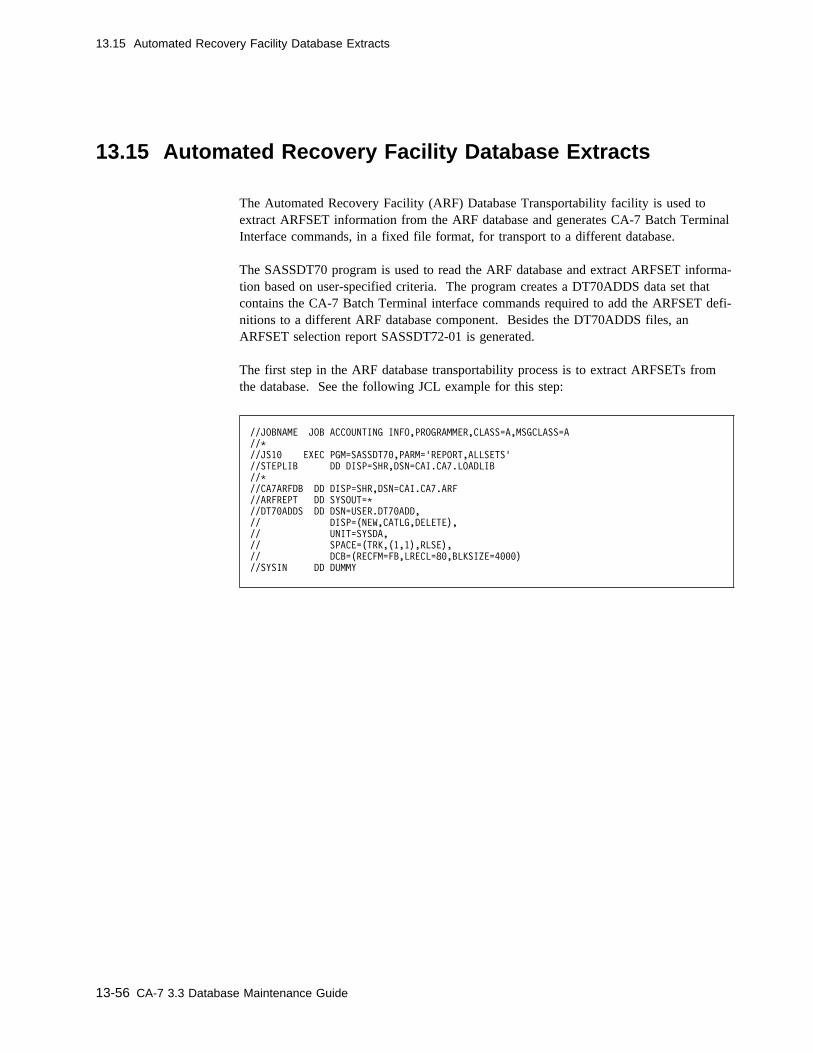
13.15 Automated Recovery Facility Database Extracts
13.15 Automated Recovery Facility Database Extracts
The Automated Recovery Facility (ARF) Database Transportability facility is used toextract ARFSET information from the ARF database and generates CA-7 Batch TerminalInterface commands, in a fixed file format, for transport to a different database.
The SASSDT70 program is used to read the ARF database and extract ARFSET informa-tion based on user-specified criteria. The program creates a DT70ADDS data set thatcontains the CA-7 Batch Terminal interface commands required to add the ARFSET defi-nitions to a different ARF database component. Besides the DT70ADDS files, anARFSET selection report SASSDT72-01 is generated.
The first step in the ARF database transportability process is to extract ARFSETs fromthe database. See the following JCL example for this step:
//JOBNAME JOB ACCOUNTING INFO,PROGRAMMER,CLASS=A,MSGCLASS=A
//C
//JS1� EXEC PGM=SASSDT7�,PARM='REPORT,ALLSETS'
//STEPLIB DD DISP=SHR,DSN=CAI.CA7.LOADLIB
//C
//CA7ARFDB DD DISP=SHR,DSN=CAI.CA7.ARF
//ARFREPT DD SYSOUT=C
//DT7�ADDS DD DSN=USER.DT7�ADD,
// DISP=(NEW,CATLG,DELETE),
// UNIT=SYSDA,
// SPACE=(TRK,(1,1),RLSE),
// DCB=(RECFM=FB,LRECL=8�,BLKSIZE=4���)
//SYSIN DD DUMMY
13-56 CA-7 3.3 Database Maintenance Guide
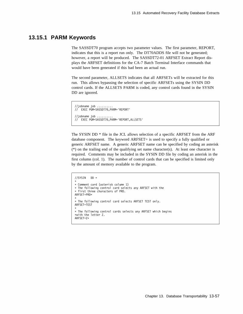
13.15 Automated Recovery Facility Database Extracts
13.15.1 PARM Keywords
The SASSDT70 program accepts two parameter values. The first parameter, REPORT,indicates that this is a report run only. The DT70ADDS file will not be generated;however, a report will be produced. The SASSDT72-01 ARFSET Extract Report dis-plays the ARFSET definitions for the CA-7 Batch Terminal Interface commands thatwould have been generated if this had been an actual run.
The second parameter, ALLSETS indicates that all ARFSETs will be extracted for thisrun. This allows bypassing the selection of specific ARFSETs using the SYSIN DDcontrol cards. If the ALLSETS PARM is coded, any control cards found in the SYSINDD are ignored.
//jobname job ..........
// EXEC PGM=SASSDT7�,PARM='REPORT'
//jobname job ..........
// EXEC PGM=SASSDT7�,PARM='REPORT,ALLSETS'
The SYSIN DD * file in the JCL allows selection of a specific ARFSET from the ARFdatabase component. The keyword ARFSET= is used to specify a fully qualified orgeneric ARFSET name. A generic ARFSET name can be specified by coding an asterisk(*) on the trailing end of the qualifying set name character(s). At least one character isrequired. Comments may be included in the SYSIN DD file by coding an asterisk in thefirst column (col. 1). The number of control cards that can be specified is limited onlyby the amount of memory available to the program.
//SYSIN DD C
C
C Comment card (asterisk column 1)
C The following control card selects any ARFSET with the
C first three characters of PRD.
ARFSET=PRDC
C
C The following control card selects ARFSET TEST only.
ARFSET=TEST
C
C The following control cards selects any ARFSET which begins
Cwith the letter Z.
ARFSET=ZC
Chapter 13. Database Transportability 13-57
13.15 Automated Recovery Facility Database Extracts
13.15.2 Data Sets Used/Created
CA7ARFDBThis is the CA-7 ARF database component.
DT70ADDSThis is the generated CA-7 Batch Terminal Interface commands file. This file isused as input into a CA-7 BTI job to add the ARFSET definitions to a different ARFdatabase.
SYSINThis file contains the control cards used to specify which ARFSETs will be extractedfor this run.
ARFREPTThis is the SASSDT72-01 ARFSET Extract Report file.
Note: The second step of the ARF Database Transportability process is to run a CA-7Batch Terminal Interface job using the generated DT70ADDS file as SYSIN inputto add the ARFSET definitions on the target ARF database.
13-58 CA-7 3.3 Database Maintenance Guide
Index
Special Characters# statements
See ?
AAbends 3-7Access restrictions 1-10Accessing files 10-5Active area
appending JCL card-image data 10-3defined 11-1, 11-3saving documentation 7-2saving schedule IDs 3-15
Active job resources display screen 5-15ADD function, alias 1-20Adding
application data sets at new site 13-22base calendars (DB.2.8 screen) 3-55CA-Librarian JCL at new site 13-26CA-Panvalet JCL at new site 13-29cataloged procedures at new site 13-32CPU job at new site 13-13data set
level documentation member to database 7-16requirements 4-8to database 9-2, 9-6
DD level documentation member to database 7-20documentation at new site 13-34input network
schedule to database 3-25SCHID to work area 3-28
joblevel documentation member to database 7-5schedule member to database 3-12SCHID to work area 3-15to database 2-2, 2-4
networkat new site 13-19level documentation member to database 7-8to database 8-2, 8-4
output networkschedule to database 3-37SCHID to work area 3-40
PDSJCL members at new site 13-24member containing JCL 10-4
Adding (continued)schedules at new site 13-36system level documentation member to database 7-24user level documentation member to database 7-12
Address space resources 5-2Adjusting schedule days 3-16, 3-29Aliases 1-20, 1-23
for formatted screen functions 1-20, 1-23Altering resolved schedule information for job or input
network 3-52Alternate JCL libraries 10-31Analyze
application 13-6commands 12-6
APA reporting 1-13APPEND function, alias 1-20Appending
data set level documentation data 7-16DD level documentation data 7-20documentation data 7-24JCL card-image data in Active Area 10-3job level documentation data 7-5network level documentation data 7-8user level documentation data 7-12
Application data sets 13-22Application System Documentation screen 7-23AR.3 screen 6-10ARF (Automated Recovery Facility)
AR.3 screen 6-10ARF Condition Definition Edit screen 6-12ARF statement 10-14overview 1-9, 6-1
ARF statement 10-13ARFSETs
defining 6-2overriding 10-14
Automated Performance Analysis (APA) reporting 1-13Automated Production Control system 1-6
BBase calendars
and database transportability 13-4defined 3-2, 3-3
Batch Card Load Program (BCLP) 1-11Batch input 1-22Batch Terminal Interface (BTI)
See BTI
Index X-1
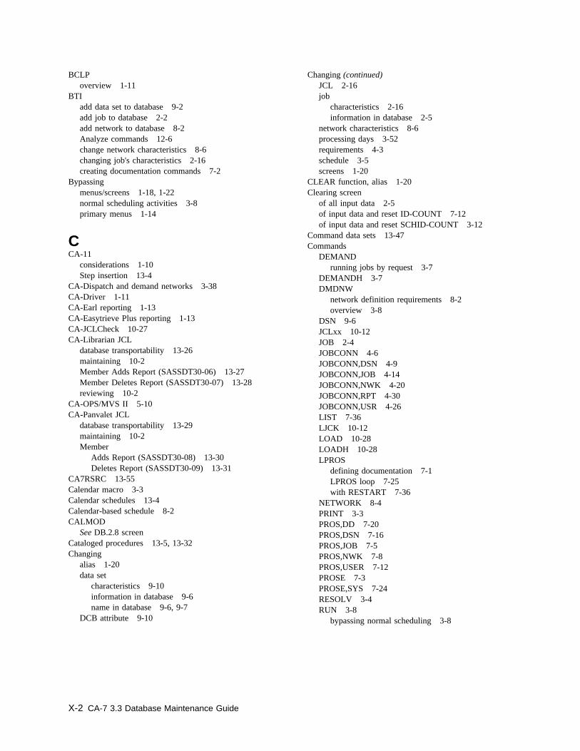
BCLPoverview 1-11
BTIadd data set to database 9-2add job to database 2-2add network to database 8-2Analyze commands 12-6change network characteristics 8-6changing job's characteristics 2-16creating documentation commands 7-2
Bypassingmenus/screens 1-18, 1-22normal scheduling activities 3-8primary menus 1-14
CCA-11
considerations 1-10Step insertion 13-4
CA-Dispatch and demand networks 3-38CA-Driver 1-11CA-Earl reporting 1-13CA-Easytrieve Plus reporting 1-13CA-JCLCheck 10-27CA-Librarian JCL
database transportability 13-26maintaining 10-2Member Adds Report (SASSDT30-06) 13-27Member Deletes Report (SASSDT30-07) 13-28reviewing 10-2
CA-OPS/MVS II 5-10CA-Panvalet JCL
database transportability 13-29maintaining 10-2Member
Adds Report (SASSDT30-08) 13-30Deletes Report (SASSDT30-09) 13-31
CA7RSRC 13-55Calendar macro 3-3Calendar schedules 13-4Calendar-based schedule 8-2CALMOD
See DB.2.8 screenCataloged procedures 13-5, 13-32Changing
alias 1-20data set
characteristics 9-10information in database 9-6name in database 9-6, 9-7
DCB attribute 9-10
Changing (continued)JCL 2-16job
characteristics 2-16information in database 2-5
network characteristics 8-6processing days 3-52requirements 4-3schedule 3-5screens 1-20
CLEAR function, alias 1-20Clearing screen
of all input data 2-5of input data and reset ID-COUNT 7-12of input data and reset SCHID-COUNT 3-12
Command data sets 13-47Commands
DEMANDrunning jobs by request 3-7
DEMANDH 3-7DMDNW
network definition requirements 8-2overview 3-8
DSN 9-6JCLxx 10-12JOB 2-4JOBCONN 4-6JOBCONN,DSN 4-9JOBCONN,JOB 4-14JOBCONN,NWK 4-20JOBCONN,RPT 4-30JOBCONN,USR 4-26LIST 7-36LJCK 10-12LOAD 10-28LOADH 10-28LPROS
defining documentation 7-1LPROS loop 7-25with RESTART 7-36
NETWORK 8-4PRINT 3-3PROS,DD 7-20PROS,DSN 7-16PROS,JOB 7-5PROS,NWK 7-8PROS,USER 7-12PROSE 7-3PROSE,SYS 7-24RESOLV 3-4RUN 3-8
bypassing normal scheduling 3-8
X-2 CA-7 3.3 Database Maintenance Guide

Commands (continued)RUNH 3-8RUNNW 3-8SCHD 3-9SCHD,DTRG 3-46SCHD,INWK 3-25SCHD,JOB 3-12SCHD,JTRG 3-44SCHD,NTRG 3-45SCHD,ONWK 3-37SCHDMOD 3-52
Commas in data 13-6Common formatted screen fields 1-15Condition code tests 10-18Conditions for adding job 2-2Control statements
"#ARF" 10-14"#JEND" 10-10"#JI" 10-7"#JO" 10-7"#MSG" 10-16"#RES" 10-17"#SCC" 10-18"#XEND" 10-10"#XI" 10-10"#XO" 10-10
Control statements, reserved 10-6Corequisite resources 5-2Corequisite resources list screen 5-23CPM 5-10CPU
Job Definition screen 2-3job dependency relationships 2-16Job Documentation screen 7-4Job Predecessors screen 4-13job schedules 13-36, 13-40Job Scheduling Parameter Edit commands 3-15Job Scheduling Parameter Edit screen 3-14Job Scheduling screen 3-11
Creatingcommand files 13-41processing schedules for
jobs scheduled on date/time basis 3-4workstation networks scheduled on date/time
basis 3-4temporary JCL 10-29, 10-31
Criteria for scheduling 3-14Critical Path Monitoring 5-10
DData Set
Definition screen 9-5Documentation screen 7-15Predecessors screen 4-8Triggering screen 3-46
Data setsadding 9-1allocation 1-10connections 4-12defined as preexecution requirement 9-4dynamically allocated 9-4level documentation 7-15maintaining 9-1triggers 3-6, 13-37
DatabaseAdds Part 1 report (SASSDT30-01) 13-14Adds Part 2 report (SASSDT30-02) 13-16Deletes report (SASSDT30-03) 13-17Disables report (SASSDT30-04) 13-18extraction 13-8Maintenance Menu 1-17resynchronizing with new JCL 2-16transportability
overview 13-1special considerations 13-50
verification 12-1Date and time stamp 1-15Date/time-driven scheduling 3-2, 3-3DB
command 1-17commands 1-14function, alias 1-20menu screens 1-14, 1-17
DB.1 screenadding job to database 2-2changing job's characteristics 2-16entering CPU job data 2-3JCL change made outside CA-7 2-16job marked MAINT=Y 4-12
DB.2 screen 3-9DB.2.1 screen
definingoptions for CPU jobs 3-11
DB.2.2 screendefining calendar-based schedule 8-2scheduling options for input networks 3-24
DB.2.3 screendefining options for output network schedules 3-36entering schedule parameters 8-2
Index X-3
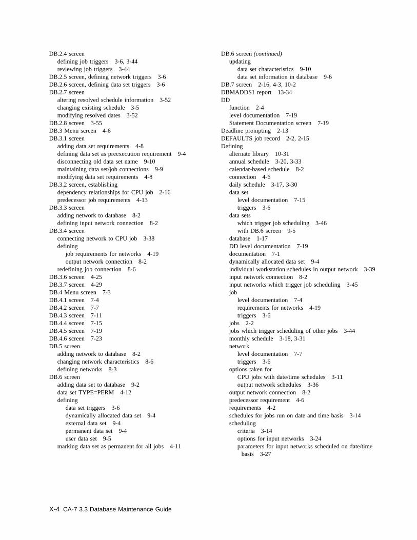
DB.2.4 screendefining job triggers 3-6, 3-44reviewing job triggers 3-44
DB.2.5 screen, defining network triggers 3-6DB.2.6 screen, defining data set triggers 3-6DB.2.7 screen
altering resolved schedule information 3-52changing existing schedule 3-5modifying resolved dates 3-52
DB.2.8 screen 3-55DB.3 Menu screen 4-6DB.3.1 screen
adding data set requirements 4-8defining data set as preexecution requirement 9-4disconnecting old data set name 9-10maintaining data set/job connections 9-9modifying data set requirements 4-8
DB.3.2 screen, establishingdependency relationships for CPU job 2-16predecessor job requirements 4-13
DB.3.3 screenadding network to database 8-2defining input network connection 8-2
DB.3.4 screenconnecting network to CPU job 3-38defining
job requirements for networks 4-19output network connection 8-2
redefining job connection 8-6DB.3.6 screen 4-25DB.3.7 screen 4-29DB.4 Menu screen 7-3DB.4.1 screen 7-4DB.4.2 screen 7-7DB.4.3 screen 7-11DB.4.4 screen 7-15DB.4.5 screen 7-19DB.4.6 screen 7-23DB.5 screen
adding network to database 8-2changing network characteristics 8-6defining networks 8-3
DB.6 screenadding data set to database 9-2data set TYPE=PERM 4-12defining
data set triggers 3-6dynamically allocated data set 9-4external data set 9-4permanent data set 9-4user data set 9-5
marking data set as permanent for all jobs 4-11
DB.6 screen (continued)updating
data set characteristics 9-10data set information in database 9-6
DB.7 screen 2-16, 4-3, 10-2DBMADDS1 report 13-34DD
function 2-4level documentation 7-19Statement Documentation screen 7-19
Deadline prompting 2-13DEFAULTS job record 2-2, 2-15Defining
alternate library 10-31annual schedule 3-20, 3-33calendar-based schedule 8-2connection 4-6daily schedule 3-17, 3-30data set
level documentation 7-15triggers 3-6
data setswhich trigger job scheduling 3-46with DB.6 screen 9-5
database 1-17DD level documentation 7-19documentation 7-1dynamically allocated data set 9-4individual workstation schedules in output network 3-39input network connection 8-2input networks which trigger job scheduling 3-45job
level documentation 7-4requirements for networks 4-19triggers 3-6
jobs 2-2jobs which trigger scheduling of other jobs 3-44monthly schedule 3-18, 3-31network
level documentation 7-7triggers 3-6
options taken forCPU jobs with date/time schedules 3-11output network schedules 3-36
output network connection 8-2predecessor requirement 4-6requirements 4-2schedules for jobs run on date and time basis 3-14scheduling
criteria 3-14options for input networks 3-24parameters for input networks scheduled on date/time
basis 3-27
X-4 CA-7 3.3 Database Maintenance Guide
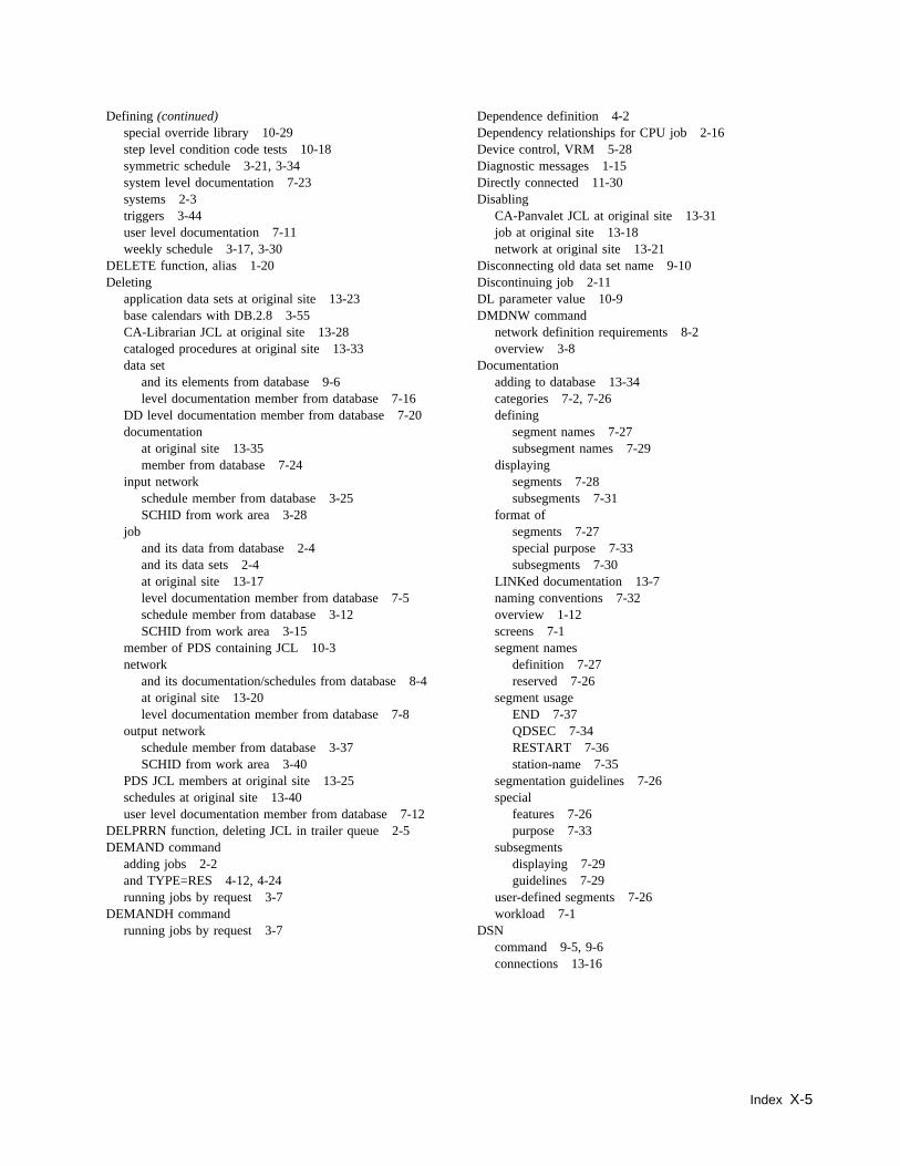
Defining (continued)special override library 10-29step level condition code tests 10-18symmetric schedule 3-21, 3-34system level documentation 7-23systems 2-3triggers 3-44user level documentation 7-11weekly schedule 3-17, 3-30
DELETE function, alias 1-20Deleting
application data sets at original site 13-23base calendars with DB.2.8 3-55CA-Librarian JCL at original site 13-28cataloged procedures at original site 13-33data set
and its elements from database 9-6level documentation member from database 7-16
DD level documentation member from database 7-20documentation
at original site 13-35member from database 7-24
input networkschedule member from database 3-25SCHID from work area 3-28
joband its data from database 2-4and its data sets 2-4at original site 13-17level documentation member from database 7-5schedule member from database 3-12SCHID from work area 3-15
member of PDS containing JCL 10-3network
and its documentation/schedules from database 8-4at original site 13-20level documentation member from database 7-8
output networkschedule member from database 3-37SCHID from work area 3-40
PDS JCL members at original site 13-25schedules at original site 13-40user level documentation member from database 7-12
DELPRRN function, deleting JCL in trailer queue 2-5DEMAND command
adding jobs 2-2and TYPE=RES 4-12, 4-24running jobs by request 3-7
DEMANDH commandrunning jobs by request 3-7
Dependence definition 4-2Dependency relationships for CPU job 2-16Device control, VRM 5-28Diagnostic messages 1-15Directly connected 11-30Disabling
CA-Panvalet JCL at original site 13-31job at original site 13-18network at original site 13-21
Disconnecting old data set name 9-10Discontinuing job 2-11DL parameter value 10-9DMDNW command
network definition requirements 8-2overview 3-8
Documentationadding to database 13-34categories 7-2, 7-26defining
segment names 7-27subsegment names 7-29
displayingsegments 7-28subsegments 7-31
format ofsegments 7-27special purpose 7-33subsegments 7-30
LINKed documentation 13-7naming conventions 7-32overview 1-12screens 7-1segment names
definition 7-27reserved 7-26
segment usageEND 7-37QDSEC 7-34RESTART 7-36station-name 7-35
segmentation guidelines 7-26special
features 7-26purpose 7-33
subsegmentsdisplaying 7-29guidelines 7-29
user-defined segments 7-26workload 7-1
DSNcommand 9-5, 9-6connections 13-16
Index X-5
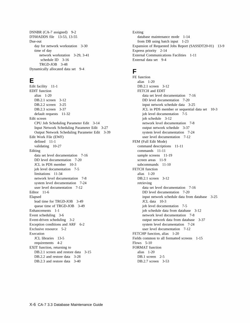
DSNBR (CA-7 assigned) 9-2DT60ADDS file 13-53, 13-55Due-out
day for network workstation 3-30time of day
network workstation 3-29, 3-41 schedule ID 3-16TRGD-JOB 3-48
Dynamically allocated data set 9-4
EEdit facility 11-1EDIT function
alias 1-20DB.2.1 screen 3-12DB.2.2 screen 3-25DB.2.3 screen 3-37default requests 11-32
Edit screenCPU Job Scheduling Parameter Edit 3-14Input Network Scheduling Parameter Edit 3-27Output Network Scheduling Parameter Edit 3-39
Edit Work File (EWF)defined 11-1validating 10-27
Editingdata set level documentation 7-16DD level documentation 7-20JCL in PDS member 10-3job level documentation 7-5limitations 11-34network level documentation 7-8system level documentation 7-24user level documentation 7-12
Editor 11-6Elapsed
lead time for TRGD-JOB 3-49queue time of TRGD-JOB 3-49
Enhancements 1-1Event scheduling 3-6Event-driven scheduling 3-2Exception conditions and ARF 6-2Exclusive resource 5-2Execution
JCL libraries 13-5requirements 4-2
EXIT function, returning toDB.2.1 screen and restore data 3-15DB.2.2 and restore data 3-28DB.2.3 and restore data 3-40
Exitingdatabase maintenance mode 1-14from DB using batch input 1-23
Expansion of Requested Jobs Report (SASSDT20-01) 13-9Express priority 2-14External Communications Facilities 1-11External data set 9-4
FFE function
alias 1-20DB.2.1 screen 3-12FETCH and EDIT
data set level documentation 7-16DD level documentation 7-20input network schedule data 3-25JCL in PDS member or sequential data set 10-3job level documentation 7-5job schedule 3-12network level documentation 7-8output network schedule 3-37system level documentation 7-24user level documentation 7-12
FEM (Full Edit Mode)command descriptions 11-11commands 11-11sample screens 11-19screen areas 11-9subcommands 11-10
FETCH functionalias 1-20DB.2.1 screen 3-12retrieving
data set level documentation 7-16DD level documentation 7-20input network schedule data from database 3-25JCL data 10-3job level documentation 7-5job schedule data from database 3-12network level documentation 7-8output network data from database 3-37system level documentation 7-24user level documentation 7-12
FETCHP function, alias 1-20Fields common to all formatted screens 1-15Flows 5-10FORMAT function
alias 1-20DB.1 screen 2-5DB.2.7 screen 3-53
X-6 CA-7 3.3 Database Maintenance Guide
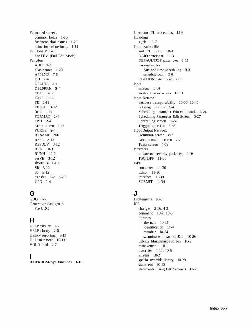
Formatted screenscommon fields 1-15functions/alias names 1-20using for online input 1-14
Full Edit ModeSee FEM (Full Edit Mode)
FunctionADD 2-4alias names 1-20APPEND 7-5DD 2-4DELETE 2-4DELPRRN 2-4EDIT 3-12EXIT 3-12FE 3-12FETCH 3-12field 1-14FORMAT 2-4LIST 2-4Menu screen 1-16PURGE 2-4RENAME 9-6REPL 3-12RESOLV 3-12RUN 10-3RUNH 10-3SAVE 3-12shortcuts 1-19SR 3-12SS 3-12transfer 1-20, 1-23UPD 2-4
GGDG 9-7Generation data group
See GDG
HHELP facility 1-7HELP library 2-6History reporting 1-13HLD statement 10-13HOLD field 2-7
IIEHPROGM-type functions 1-10
In-stream JCL procedures 13-6Including
a job 10-7Initialization file
and JCL library 10-4DAIO statement 11-3DEFAULTJOB parameter 2-15parameters for
date and time scheduling 3-3schedule scan 3-6
STATIONS statement 7-35Input
screens 1-14workstation networks 13-21
Input Networkdatabase transportability 13-38, 13-40defining 8-2, 8-3, 8-4Scheduling Parameter Edit commands 3-28Scheduling Parameter Edit Screen 3-27Scheduling screen 3-24Triggering screen 3-45
Input/Output NetworkDefinition screen 8-3Documentation screen 7-7Tasks screen 4-19
Interfacesto external security packages 1-10TSO/ISPF 11-30
ISPFconnected 11-30Editor 11-30interface 11-30SUBMIT 11-34
JJ statements 10-6JCL
changes 2-16, 4-3command 10-2, 10-3libraries
alternate 10-31identification 10-4member 10-24scanning with sample JCL 10-26
Library Maintenance screen 10-2management 10-1overrides 1-11, 10-6screens 10-2special override library 10-29statement 10-13statements (using DB.7 screen) 10-2
Index X-7
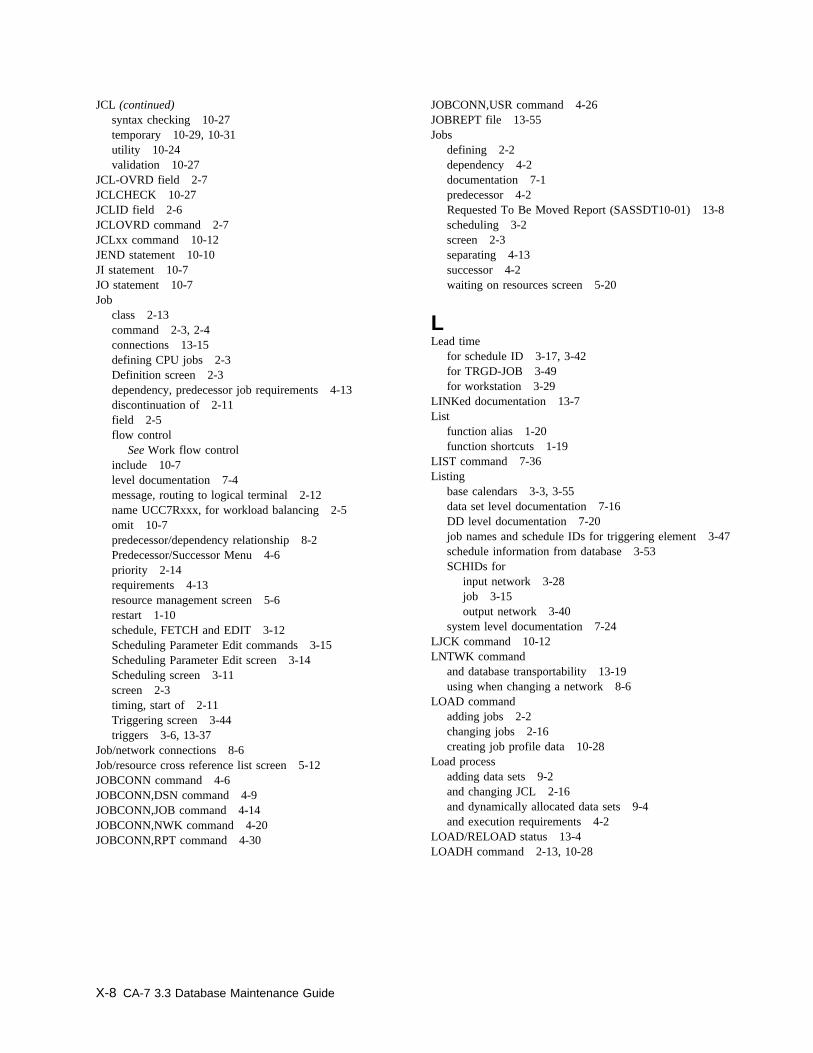
JCL (continued)syntax checking 10-27temporary 10-29, 10-31utility 10-24validation 10-27
JCL-OVRD field 2-7JCLCHECK 10-27JCLID field 2-6JCLOVRD command 2-7JCLxx command 10-12JEND statement 10-10JI statement 10-7JO statement 10-7Job
class 2-13command 2-3, 2-4connections 13-15defining CPU jobs 2-3Definition screen 2-3dependency, predecessor job requirements 4-13discontinuation of 2-11field 2-5flow control
See Work flow controlinclude 10-7level documentation 7-4message, routing to logical terminal 2-12name UCC7Rxxx, for workload balancing 2-5omit 10-7predecessor/dependency relationship 8-2Predecessor/Successor Menu 4-6priority 2-14requirements 4-13resource management screen 5-6restart 1-10schedule, FETCH and EDIT 3-12Scheduling Parameter Edit commands 3-15Scheduling Parameter Edit screen 3-14Scheduling screen 3-11screen 2-3timing, start of 2-11Triggering screen 3-44triggers 3-6, 13-37
Job/network connections 8-6Job/resource cross reference list screen 5-12JOBCONN command 4-6JOBCONN,DSN command 4-9JOBCONN,JOB command 4-14JOBCONN,NWK command 4-20JOBCONN,RPT command 4-30
JOBCONN,USR command 4-26JOBREPT file 13-55Jobs
defining 2-2dependency 4-2documentation 7-1predecessor 4-2Requested To Be Moved Report (SASSDT10-01) 13-8scheduling 3-2screen 2-3separating 4-13successor 4-2waiting on resources screen 5-20
LLead time
for schedule ID 3-17, 3-42for TRGD-JOB 3-49for workstation 3-29
LINKed documentation 13-7List
function alias 1-20function shortcuts 1-19
LIST command 7-36Listing
base calendars 3-3, 3-55data set level documentation 7-16DD level documentation 7-20job names and schedule IDs for triggering element 3-47schedule information from database 3-53SCHIDs for
input network 3-28job 3-15output network 3-40
system level documentation 7-24LJCK command 10-12LNTWK command
and database transportability 13-19using when changing a network 8-6
LOAD commandadding jobs 2-2changing jobs 2-16creating job profile data 10-28
Load processadding data sets 9-2and changing JCL 2-16and dynamically allocated data sets 9-4and execution requirements 4-2
LOAD/RELOAD status 13-4LOADH command 2-13, 10-28
X-8 CA-7 3.3 Database Maintenance Guide
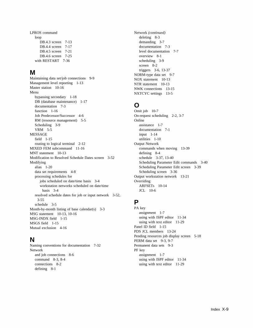
LPROS commandloop
DB.4.3 screen 7-13DB.4.4 screen 7-17DB.4.5 screen 7-21DB.4.6 screen 7-25
with RESTART 7-36
MMaintaining data set/job connections 9-9Management level reporting 1-13Master station 10-16Menu
bypassing secondary 1-18DB (database maintenance) 1-17documentation 7-3function 1-16Job Predecessor/Successor 4-6RM (resource management) 5-5Scheduling 3-9VRM 5-5
MESSAGEfield 1-15routing to logical terminal 2-12
MIXED FEM subcommand 11-16MNT statement 10-13Modification to Resolved Schedule Dates screen 3-52Modifying
alias 1-20data set requirements 4-8processing schedules for
jobs scheduled on date/time basis 3-4workstation networks scheduled on date/time
basis 3-4resolved schedule dates for job or input network 3-52,
3-55schedule 3-5
Month-by-month listing of base calendar(s) 3-3MSG statement 10-13, 10-16MSG-INDX field 1-15MSGS field 1-15Mutual exclusion 4-16
NNaming conventions for documentation 7-32Network
and job connections 8-6command 8-3, 8-4connections 8-2defining 8-1
Network (continued)deleting 8-3demanding 3-7documentation 7-3level documentation 7-7overview 8-1scheduling 3-9screen 8-2triggers 3-6, 13-37
NORM-type data set 9-7NOX statement 10-13NTR statement 10-13NWK connections 13-15NXTCYC settings 13-5
OOmit job 10-7On-request scheduling 2-2, 3-7Online
assistance 1-7documentation 7-1input 1-14utilities 1-10
Output Networkcommands when moving 13-39defining 8-4schedule 3-37, 13-40Scheduling Parameter Edit commands 3-40Scheduling Parameter Edit screen 3-39Scheduling screen 3-36
Output workstation network 13-21Overriding
ARFSETs 10-14JCL 10-6
PPA key
assignment 1-7using with ISPF editor 11-34using with text editor 11-29
Panel ID field 1-15PDS JCL members 13-24Pending resources job display screen 5-18PERM data set 9-3, 9-7Permanent data sets 9-3PF key
assignment 1-7using with ISPF editor 11-34using with text editor 11-29
Index X-9
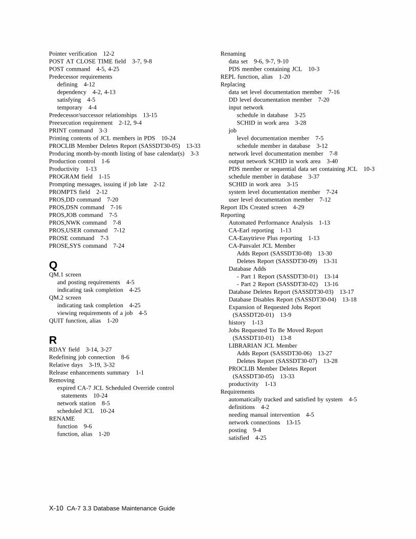
Pointer verification 12-2POST AT CLOSE TIME field 3-7, 9-8POST command 4-5, 4-25Predecessor requirements
defining 4-12dependency 4-2, 4-13satisfying 4-5temporary 4-4
Predecessor/successor relationships 13-15Preexecution requirement 2-12, 9-4PRINT command 3-3Printing contents of JCL members in PDS 10-24PROCLIB Member Deletes Report (SASSDT30-05) 13-33Producing month-by-month listing of base calendar(s) 3-3Production control 1-6Productivity 1-13PROGRAM field 1-15Prompting messages, issuing if job late 2-12PROMPTS field 2-12PROS,DD command 7-20PROS,DSN command 7-16PROS,JOB command 7-5PROS,NWK command 7-8PROS,USER command 7-12PROSE command 7-3PROSE,SYS command 7-24
QQM.1 screen
and posting requirements 4-5indicating task completion 4-25
QM.2 screenindicating task completion 4-25viewing requirements of a job 4-5
QUIT function, alias 1-20
RRDAY field 3-14, 3-27Redefining job connection 8-6Relative days 3-19, 3-32Release enhancements summary 1-1Removing
expired CA-7 JCL Scheduled Override controlstatements 10-24
network station 8-5scheduled JCL 10-24
RENAMEfunction 9-6function, alias 1-20
Renamingdata set 9-6, 9-7, 9-10PDS member containing JCL 10-3
REPL function, alias 1-20Replacing
data set level documentation member 7-16DD level documentation member 7-20input network
schedule in database 3-25SCHID in work area 3-28
joblevel documentation member 7-5schedule member in database 3-12
network level documentation member 7-8output network SCHID in work area 3-40PDS member or sequential data set containing JCL 10-3schedule member in database 3-37SCHID in work area 3-15system level documentation member 7-24user level documentation member 7-12
Report IDs Created screen 4-29Reporting
Automated Performance Analysis 1-13CA-Earl reporting 1-13CA-Easytrieve Plus reporting 1-13CA-Panvalet JCL Member
Adds Report (SASSDT30-08) 13-30Deletes Report (SASSDT30-09) 13-31
Database Adds- Part 1 Report (SASSDT30-01) 13-14- Part 2 Report (SASSDT30-02) 13-16
Database Deletes Report (SASSDT30-03) 13-17Database Disables Report (SASSDT30-04) 13-18Expansion of Requested Jobs Report
(SASSDT20-01) 13-9history 1-13Jobs Requested To Be Moved Report
(SASSDT10-01) 13-8LIBRARIAN JCL Member
Adds Report (SASSDT30-06) 13-27Deletes Report (SASSDT30-07) 13-28
PROCLIB Member Deletes Report(SASSDT30-05) 13-33
productivity 1-13Requirements
automatically tracked and satisfied by system 4-5definitions 4-2needing manual intervention 4-5network connections 13-15posting 9-4satisfied 4-25
X-10 CA-7 3.3 Database Maintenance Guide
RES statement 10-13, 10-17RESANL command 2-14, 2-15, 12-6Reserved DDname Table 9-3RESOLV
command 3-4function
overview 3-4using with DB.2.1 screen 3-12using with DB.2.2 screen 3-25
RESOLV function alias 1-20Resource count resource management screen 5-25Resource count resources 5-3Resources
address space 5-2corequisite 5-2exclusive 5-2handling 5-4resource count 5-3shared 5-2
Restricting access 1-10Resynchronizing database with new JCL 2-16Retrieving
data set level documentation 7-16DD level documentation 7-20input network schedule data from database 3-25JCL data 10-3job
level documentation 7-5schedule data from database 3-12
network level documentation 7-8output network data from database 3-37system level documentation 7-24user level documentation 7-12
Returningto DB.2.1 screen and restoring data 3-15to DB.2.2 screen and restoring data 3-28to DB.2.3 screen and restoring data 3-40
ReviewingCA-Librarian JCL 10-2CA-Panvalet JCL 10-2CPU job data 2-3data sets which trigger job scheduling 3-46individual workstation schedules in output network 3-39input networks which trigger job scheduling 3-45JCL statements
in PDS 10-2in sequential JCL library 10-2
jobs which trigger scheduling of other jobs 3-44options taken for
CPU jobs with date/time schedules 3-11output network schedules 3-36
schedules for jobs run on date and time basis 3-14
Reviewing (continued)scheduling
options for input networks 3-24parameters for input networks scheduled on date and
time basis 3-27RM Menu screen 5-5RM.1 screen 5-6RM.2 screen 5-12RM.3 screen 5-15RM.4 screen 5-18RM.5 screen 5-20RM.6 screen 5-23RM.7 screen 5-25ROLL field
defining/reviewing schedules 3-14defining/reviewing schedules for input networks 3-27
Rolling scheduleback 3-16, 3-29forward 3-16, 3-29
Routing message about job to logical terminal 2-12RPT (Reports Processing and Tracking)
and demand networks 3-38RQMT command 12-6RQVER command 12-6RSRC keyword 5-10, 5-27RUN command
and true predecessor requirements 4-12, 4-24bypassing normal scheduling 3-8
RUN function 10-3RUNH command
assigned to class 9 2-13bypassing normal scheduling 3-8
RUNH function on DB.7 screen 10-3RUNNW command 3-8, 8-2
SSASSBSTR program 13-44
producing listings 13-44SASSDT10
execution JCL 13-43module 13-44
SASSDT10-01 report 13-8, 13-43SASSDT20
execution JCL 13-45module
CA-Librarian JCL 13-26CA-Panvalet JCL 13-29cataloged procedures 13-32expanding requested job 13-9PDS JCL members 13-24
Index X-11
SASSDT20-01 report 13-9, 13-45SASSDT30
execution JCL 13-49module 13-10, 13-46, 13-47
SASSDT30-01 reportadding at new site
application data sets 13-22documentation 13-35PDS JCL members 13-24workstation networks 13-19
sample report 13-14SASSDT30-02 report
adding schedules at new site 13-36, 13-38, 13-39sample report 13-16
SASSDT30-03 report 13-17, 13-35SASSDT30-04 report 13-18SASSDT30-05 report 13-33SASSDT30-06 report 13-27SASSDT30-07 report 13-28SASSDT30-08 report 13-30SASSDT30-09 report 13-31SASSDT60
execution JCL 13-54module 13-53
SASSDT60-01 report 13-53SASSDTAB table 5-28SASSJCLU batch utility 10-24SASSMSGS module 7-34, 7-35SASSPMDD table 9-3SASSUTBL module 2-14Satisfying requirements 4-5SAVE function
addingdata set level documentation member to
database 7-16DD level documentation member to database 7-20input network schedule to database 3-25job level documentation member to database 7-5job schedule member to database 3-12job SCHID-COUNT and SCHID in work area 3-15network level documentation member to database 7-8output network schedule to database 3-37PDS member containing JCL 10-4system level documentation member to database 7-24user level documentation member to database 7-12
alias 1-20replacing sequential data set containing JCL 10-4updating
input network SCHID-COUNT and SCHID in workarea 3-28
output network SCHID-COUNT and SCHID in workarea 3-40
SCAL field 3-13SCC statement 10-13, 10-18SCHD command 3-9SCHD,DTRG command 3-46SCHD,INWK command 3-25SCHD,JOB command 3-12SCHD,JTRG command 3-44SCHD,NTRG command 3-45SCHD,ONWK command 3-37SCHDMOD command 3-52Schedule
adding at new site 13-36defining 3-4deleting at original site 13-40ID, importance of 3-2modifications 3-5, 13-4resolving 3-4triggers
data set 3-6job 3-6network 3-6
Schedule scandate and time scheduling 3-3overview 3-6
Schedulingentering parameters 8-2JCL overrides 10-6job, trigger 3-43Menu 3-9overview 3-2Relative days 3-19, 3-32screen 3-9
SCHID field 3-15, 3-28, 3-40, 3-48, 3-53Screen to screen transfer 1-20Screens
Active Job Resources Display 5-15Application System Documentation 7-23bypassing 1-18common fields 1-15Corequisite Resources list 5-23CPU Job
Definition 2-3Documentation 7-4Predecessors 4-13Scheduling 3-11Scheduling Parameter Edit 3-14
Data SetDefinition 9-5Documentation 7-15Predecessors 4-8Triggering 3-46
DB Menu 1-17
X-12 CA-7 3.3 Database Maintenance Guide
Screens (continued)DD Statement Documentation 7-19edit 3-12, 3-39Function Menu 1-16Input Network
Scheduling 3-24Scheduling Parameter Edit 3-27Triggering 3-45
Input/Output NetworkDefinition 8-3Documentation 7-7Tasks 4-19
JCL Library Maintenance 10-2Job
Predecessor/Successor Menu 4-6Resource Management 5-6Triggering 3-44
Job/resource Cross Reference List 5-12Jobs Waiting on Resources 5-20layout 1-15Modification to Resolved Schedule Dates 3-52Output Network
Scheduling 3-36Scheduling Parameter Edit 3-39
Pending Resources Job Display 5-18Report IDs Created 4-29Resource Count Resource Management 5-25RM menu 5-5Scheduling Menu 3-9User Memo-Form Predecessors 4-25User-Defined Item Documentation 7-11Workload Documentation Menu 7-3
Security 1-10, 13-7overview 1-10user ID 13-7
SelectingDatabase Maintenance function 1-17documentation functions 7-3
Sending messages 10-16Sequence numbers 13-7Shared resources 5-2Shortcuts
bypass menus/screens 1-18, 1-22LIST function 1-19
Specialdocumentation
features 7-26messages 8-5
override library 2-6, 10-29purpose documentation 7-33
SR (SAVE/REPL) functioninput network schedule 3-28job schedule 3-15output network schedule 3-40
SS (SAVE/SAVE) functionSAVE input network schedule in database 3-28SAVE job schedule in database 3-15SAVE output network schedule in database 3-40
STATUS function, alias 1-20Status of modifications made to schedule 3-53Submitting
JCL in text editor Active Area to default MAINID 10-3time of day
for schedule ID 3-17requirement on TRGD-JOB 3-49
SUBTM command 4-5Summary of release enhancements 1-1SYSIN control cards 13-55System level documentation screen 7-23System Management Facility (SMF) interface 9-7
TTask completed 4-25Temporary JCL 10-29, 10-31Temporary predecessors 4-4Text editor 1-13, 11-1Timing
for generation of base calendar 3-3permanent discontinuation of job 2-11start of new jobs 2-11
Top line commands 1-14Transferring
from screen to screen 1-20to another DB function (batch input) 1-23to CPU Job Scheduling Parameter Edit screen 3-12to Input Network Scheduling Parameter Edit screen 3-25to Output Network Scheduling Parameter Edit
screen 3-37work from one database to another 13-1
TRIG command 12-6Trigger scheduling of job 3-43Triggers 3-6, 13-37TSO/ISPF interface 11-30TYPE field 9-7
UUCC7Rxxx, job name for workload balancing 2-5Unconnected workstation networks 13-21Unsatisfied requirements 4-5
Index X-13
UPD function, alias 1-20Updating
base calendars using DB.2.8 screen 3-55data set
characteristics 9-10information in database 9-6requirements 4-9
DESC and LINK fields ofjob level documentation member 7-5system level documentation member 7-24
formatted screen fields ofDB.4.2 screen 7-8DB.4.3 screen 7-12DB.4.4 screen 7-16DB.4.5 screen 7-20
input network SCHID-COUNT and SCHID in workarea 3-28
jobcharacteristics 2-16information in database 2-5SCHID-COUNT and SCHID in work area 3-15
networkinformation in database 8-4requirements 4-20
output network SCHID-COUNT and SCHID in workarea 3-40
predecessor job requirements in database 4-14schedule information in database for job or
network 3-53to remove network station 8-5triggering element 3-47user requirement 4-26
UPPER FEM subcommand 11-18User
ID security 13-7level documentation 7-11, 13-6Memo-Form Predecessors screen 4-25requirement 4-25
User-defineddocumentation segments 7-26Item Documentation screen 7-11
Using temporary JCL 10-30, 10-31USR connections 13-16Utility commands 1-10
RENAME 9-6, 9-10
VVariable parameter in ARF 6-38VER statement 10-13VERIFY command 2-7, 4-5
Verifying logical pointers in database 12-2VRM (Virtual Resource Management) 1-8
and database transportability 13-53DBT Job Extract JCL 13-54device control 5-28Job Extract Report 13-53Menu screen 5-5overview 5-1
WWLB
job class 2-13job name, UCC7Rxxx 2-5job priority 2-14
Work flow control 1-8commands
DEMAND 2-2, 3-7, 4-12, 4-24DEMANDH 3-7DMDNW 3-8, 8-2JCLOVRD 2-7LOAD 2-2, 2-16, 4-12, 4-24, 10-28LOADH 2-13, 10-28POST 4-5, 4-25RUN 2-2, 3-8, 4-12, 4-24RUNH 2-13, 3-8RUNNW 3-8, 8-2SUBTM 4-5VERIFY 2-7, 4-5
Work scheduling 3-2Workload
balancingoverview 1-12
documentation 1-12, 7-1documentation menu screen 7-3forecasting 1-11planning 1-12scheduling 1-8sequencing 1-8
Workstationnetwork control
See Work flow controlnetworks 8-1, 13-6, 13-19
XXEND statement 10-10XI statement 10-10XO statement 10-10XREF command 12-6
X-14 CA-7 3.3 Database Maintenance Guide

YYEAR field 3-54
Index X-15

Related Documents


![CA7-33-Commands [Wazhua.Com]](https://static.cupdf.com/doc/110x72/543d7ed7afaf9fa80a8b48a9/ca7-33-commands-wazhuacom.jpg)