C800 Cylindrical Lever Set Installation Instructions 76013497 02/18 www.dormakaba.us 1.1.1 Place latch into door edge. Orient such that the beveled edge of latch faces door jamb. 1.1.2 Secure with two 8-32 x 3/4” combo screws. PART LIST 1- IC CORE 2- OUTSIDE IC LEVER 3- OUTSIDE ROSE 4- OUTSIDE ROSE INSERT 5- THRU BOLT RETAINER 6- CHASSIS 7- INSIDE ROSE MOUNTING PLATE 8- 10-32 X 1-1/2” SCREWS (X2) 9- INSIDE ROSE 10- LEVER INSERT 11- INSIDE LEVER 12- LATCH 13- 8-32 X 3/4” COMBO SCREWS (2) 14- OUTSIDE CONVENTIONAL CYLINDER LEVER 15- CONVENTIONAL CYLINDER Beveled edge Latch bolt extension Latch bolt with extension & sleeve Latch bolt sleeve 1.2.1 Connect latch bolt extension to latch bolt. 1.2.2 Slide sleeve over top of both, extension and latch bolt. 1.2.3 Extension can be oriented in either direction. Adjust for door thickness NOTE: Lock comes adjusted for 1-3/4” door from the factory. 1.3.1 Align so center of chassis is in line with center of latch. 1.3.2 Slightly separate thru-bolt retainer from outside rose assembly. 1.4.1 Hold lock assembly in place. 1.4.2 Thread inside rose mounting onto chassis until snug against door. 1.3.3 Rotate outside rose assembly to adjust for proper door thickness. 1.3.4 Realign thru-bolt retainer with outside rose. Install chassis 1.3.5 Slide lock assembly into face of door. Be sure to engage the inner latch mechanism of the chassis with the back of the latch as shown. Center of latch Chassis Latch or latch bolt with extension 1.5.1 Push inside rose onto inside rose mounting plate. • Orientation: rose notch faces downward. NOTE: Be sure lever insert is inserted into inside lever prior to installation. 1.5.2 Push inside lever onto spindle until it clicks into place. Spanner wrench Rose mounting plate Chassis Outside rose assembly Thru-bolt retainer Inside lever Inside rose Spindle Inside rose mounting plate Rose notch location 1.6.1 Insert strike as shown, and secure with two 12-24 x 1” combo screws. STRIKE PART LIST 1 - STRIKE PLATE 2 - DUST BOX 3 - 12-24 X 1” COMBO-SCREWS Non-wood doors 3 2 1 Tools required #2 Cross drive screwdriver Flathead screwdriver 1 Cylindrical lock installation 1.1 Install latch Fig 1 1.2 Optional extension instructions Fig 2 1.3 Install lock assembly Fig 3 1.4 Install inside rose insert Fig 4 1.4.3 Ensure mounting plate is aligned with holes in door. 1.4.4 Secure mounting plate to chassis using two 10-32 x 1-1/2” screws. 1.5 Install rose Fig 5 1.6 Install strikes Fig 6 2 10 9 8 7 1 3 13 12 11 14 15 4 5 6

Welcome message from author
This document is posted to help you gain knowledge. Please leave a comment to let me know what you think about it! Share it to your friends and learn new things together.
Transcript
C800 Cylindrical Lever SetInstallation Instructions
76013497 02/18 www.dormakaba.us
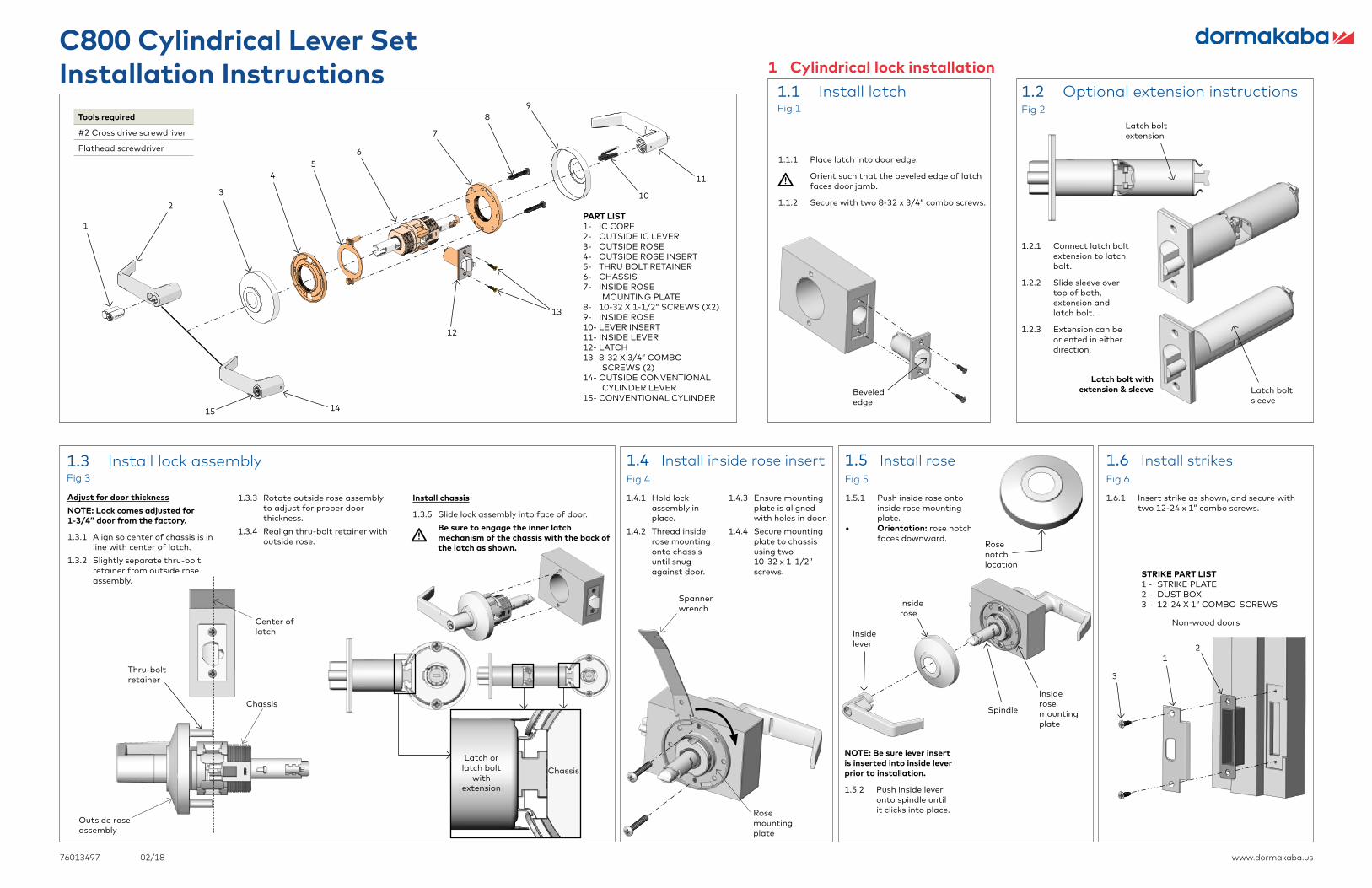
1.1.1 Place latch into door edge.
Orient such that the beveled edge of latch faces door jamb.
1.1.2 Secure with two 8-32 x 3/4” combo screws.PART LIST1- IC CORE2- OUTSIDE IC LEVER3- OUTSIDE ROSE4- OUTSIDE ROSE INSERT5- THRU BOLT RETAINER6- CHASSIS7- INSIDE ROSE
MOUNTING PLATE8- 10-32 X 1-1/2” SCREWS (X2)9- INSIDE ROSE10- LEVER INSERT11- INSIDE LEVER12- LATCH13- 8-32 X 3/4” COMBO
SCREWS (2)14- OUTSIDE CONVENTIONAL
CYLINDER LEVER15- CONVENTIONAL CYLINDER
Beveled edge
Latch boltextension
Latch bolt with extension & sleeve Latch bolt
sleeve
1.2.1 Connect latch bolt extension to latch bolt.
1.2.2 Slide sleeve over top of both, extension and latch bolt.
1.2.3 Extension can be oriented in either direction.
Adjust for door thicknessNOTE: Lock comes adjusted for 1-3/4” door from the factory.
1.3.1 Align so center of chassis is in line with center of latch.
1.3.2 Slightly separate thru-bolt retainer from outside rose assembly.
1.4.1 Hold lock assembly in place.
1.4.2 Thread inside rose mounting onto chassis until snug against door.
1.3.3 Rotate outside rose assembly to adjust for proper door thickness.
1.3.4 Realign thru-bolt retainer with outside rose.
Install chassis
1.3.5 Slide lock assembly into face of door.Be sure to engage the inner latch mechanism of the chassis with the back of the latch as shown.
Center of latch
ChassisLatch or
latch bolt with
extension
1.5.1 Push inside rose onto inside rose mounting plate.
• Orientation: rose notch faces downward.
NOTE: Be sure lever insert is inserted into inside lever prior to installation.
1.5.2 Push inside lever onto spindle until it clicks into place.
Spanner wrench
Rosemounting plate
Chassis
Outside rose assembly
Thru-boltretainer
Inside lever
Inside rose
Spindle
Insiderose mounting plate
Rosenotch location
1.6.1 Insert strike as shown, and secure with two 12-24 x 1” combo screws.
STRIKE PART LIST1 - STRIKE PLATE2 - DUST BOX3 - 12-24 X 1” COMBO-SCREWS
Non-wood doors
3
21
Tools required
#2 Cross drive screwdriver
Flathead screwdriver
1 Cylindrical lock installation1.1 Install latchFig 1
1.2 Optional extension instructionsFig 2
1.3 Install lock assemblyFig 3
1.4 Install inside rose insertFig 4
1.4.3 Ensure mounting plate is aligned with holes in door.
1.4.4 Secure mounting plate to chassis using two 10-32 x 1-1/2” screws.
1.5 Install roseFig 5
1.6 Install strikesFig 6
210
98
7
1
3
13
12
11
1415
45
6
76013497 02/18 www.dormakaba.us
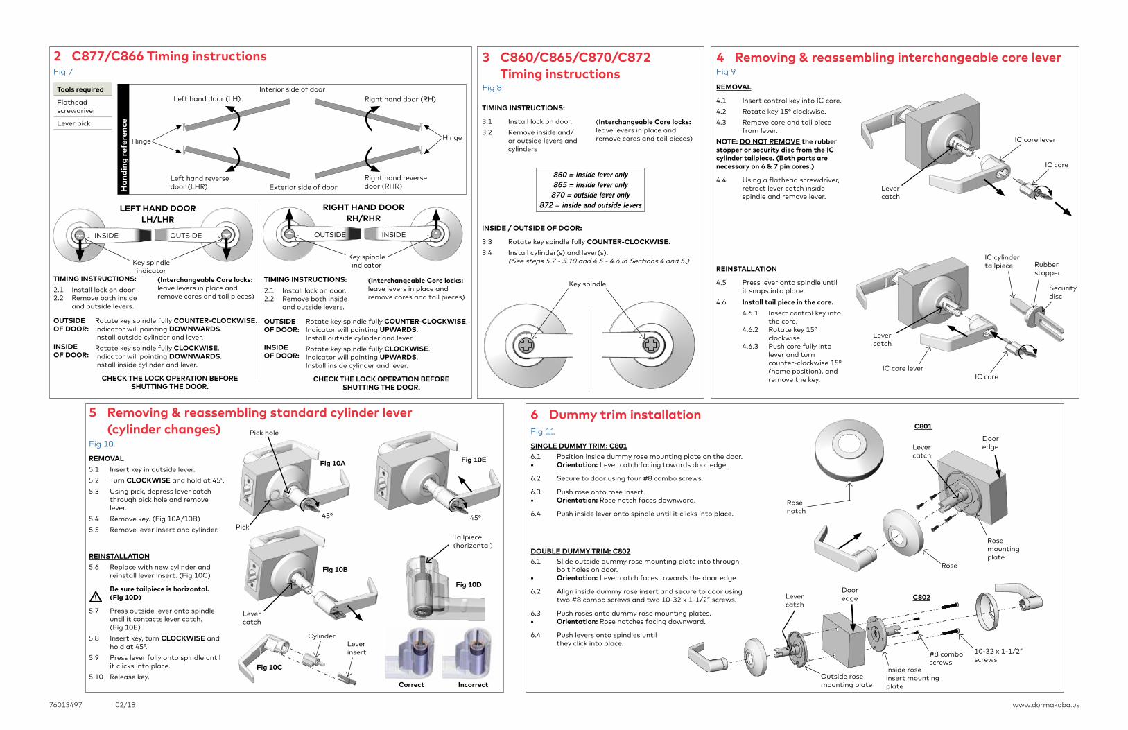
REMOVAL5.1 Insert key in outside lever. 5.2 Turn CLOCKWISE and hold at 45°. 5.3 Using pick, depress lever catch
through pick hole and remove lever.
5.4 Remove key. (Fig 10A/10B)5.5 Remove lever insert and cylinder.
REINSTALLATION5.6 Replace with new cylinder and
reinstall lever insert. (Fig 10C)
Be sure tailpiece is horizontal. (Fig 10D)
5.7 Press outside lever onto spindle until it contacts lever catch. (Fig 10E)
5.8 Insert key, turn CLOCKWISE and hold at 45°.
5.9 Press lever fully onto spindle until it clicks into place.
5.10 Release key.
REMOVAL
4.1 Insert control key into IC core.4.2 Rotate key 15° clockwise. 4.3 Remove core and tail piece
from lever.NOTE: DO NOT REMOVE the rubber stopper or security disc from the IC cylinder tailpiece. (Both parts are necessary on 6 & 7 pin cores.)
4.4 Using a flathead screwdriver, retract lever catch inside spindle and remove lever.
REINSTALLATION
4.5 Press lever onto spindle until it snaps into place.
4.6 Install tail piece in the core. 4.6.1 Insert control key into
the core.4.6.2 Rotate key 15°
clockwise.4.6.3 Push core fully into
lever and turn counter-clockwise 15° (home position), and remove the key.
6.1 Position inside dummy rose mounting plate on the door. • Orientation: Lever catch facing towards door edge.
6.2 Secure to door using four #8 combo screws.
6.3 Push rose onto rose insert. • Orientation: Rose notch faces downward.
6.4 Push inside lever onto spindle until it clicks into place.
SINGLE DUMMY TRIM: C801
6.1 Slide outside dummy rose mounting plate into through-bolt holes on door.
• Orientation: Lever catch faces towards the door edge.
6.2 Align inside dummy rose insert and secure to door using two #8 combo screws and two 10-32 x 1-1/2” screws.
6.3 Push roses onto dummy rose mounting plates.• Orientation: Rose notches facing downward.
6.4 Push levers onto spindles until they click into place.
DOUBLE DUMMY TRIM: C802
IC core
IC core lever
IC coreIC core lever
Lever catch
Rose mounting plate
Rosenotch
Lever catch
Door edge
Rose
Inside rose insert mounting plate
10-32 x 1-1/2” screws
#8 comboscrews
Lever catch
Outside rose mounting plate
Dooredge
45°45°
Fig 10A
Fig 10B
Fig 10C
Fig 10E
Pick hole
Pick
CylinderLever insert
Tailpiece(horizontal)
Levercatch
IC cylindertailpiece Rubber
stopper
Securitydisc
OUTSIDE
TIMING INSTRUCTIONS: 2.1 Install lock on door. 2.2 Remove both inside
and outside levers.
LEFT HAND DOOR LH/LHR
INSIDE
Hinge Hinge
Exterior side of door
Interior side of doorLeft hand door (LH)
Left hand reverse door (LHR)
Right hand reverse door (RHR)
Right hand door (RH)
Han
ding
refe
renc
e
C801
C802
TIMING INSTRUCTIONS:
3.1 Install lock on door. 3.2 Remove inside and/
or outside levers and cylinders
860 = inside lever only865 = inside lever only870 = outside lever only
872 = inside and outside levers
Key spindle
2 C877/C866 Timing instructionsFig 7
Tools required
Flathead screwdriver
Lever pick
Key spindle indicator
OUTSIDE
Rotate key spindle fully COUNTER-CLOCKWISE.Indicator will pointing DOWNWARDS. Install outside cylinder and lever. Rotate key spindle fully CLOCKWISE. Indicator will pointing DOWNWARDS. Install inside cylinder and lever.
CHECK THE LOCK OPERATION BEFORE SHUTTING THE DOOR.
OUTSIDE OF DOOR:
INSIDE OF DOOR:
(Interchangeable Core locks: leave levers in place and remove cores and tail pieces)
TIMING INSTRUCTIONS: 2.1 Install lock on door. 2.2 Remove both inside
and outside levers.
Rotate key spindle fully COUNTER-CLOCKWISE.Indicator will pointing UPWARDS. Install outside cylinder and lever. Rotate key spindle fully CLOCKWISE. Indicator will pointing UPWARDS. Install inside cylinder and lever.
CHECK THE LOCK OPERATION BEFORE SHUTTING THE DOOR.
OUTSIDE OF DOOR:
INSIDE OF DOOR:
(Interchangeable Core locks: leave levers in place and remove cores and tail pieces)
RIGHT HAND DOOR RH/RHR
Key spindle indicator
INSIDE
3 C860/C865/C870/C872 Timing instructions
Fig 8
INSIDE / OUTSIDE OF DOOR:
3.3 Rotate key spindle fully COUNTER-CLOCKWISE. 3.4 Install cylinder(s) and lever(s).
(See steps 5.7 - 5.10 and 4.5 - 4.6 in Sections 4 and 5.)
(Interchangeable Core locks: leave levers in place and remove cores and tail pieces)
4 Removing & reassembling interchangeable core leverFig 9
Lever catch
5 Removing & reassembling standard cylinder lever (cylinder changes)
Fig 10D
IncorrectCorrect
6 Dummy trim installation
Fig 10Fig 11
Related Documents