IINCH-POUND] MIL-B-16115G 28 June 1991 SUPERSEDING MIL-B-16115F 21 August 197g MILITARY SPECIFICATION BUOYS, MOORING, AND MARKER This specification is approved for use by all Departments and Agencies of the Department of Defense. 1. SCOPE 1.1 scoDe. This specification covers marker buoys and telephone, and cylindrical mooring buoys used in mooring systems; a peg top buoy cylindrical upper portion, a frustum shaped lower portion and tension peg top, having a bars. 1.2 Classification. Buoys will be of the following types and sizes as specified (see 6.2): Type II - Telephone mooring buoy. I Size 14 - 14 feet diameter, 7 feet deep. Size 16 - 16 feet diameter, 8-1/2 feet deep. Size 17 - 17 feet diameter, 10-1/2 feet deep. Type III - Marker buoy. Size 3-1/2 - 3-1/2 feet diameter, spherical shape. Type IV - Peg top mooring buoy. Size 12 - 12 feet diameter, 9-1/2 feet deep. IBeneficial comments (recommendations, additions, deletions) and any pertinent , ldata which may be of use in improving this document shouldbe addressed to: I lCommanding Officer (Code 156), Naval Construction Battalion Center, Port I [Hueneme, CA 93043-5000, by using the self-addressed Standardization I [Document Improvement Proposal (DD Form 1426) appearing at the end of this I ldocument or by letter. I AMSC N/A FSC 2050 DISTRIBUTION STATEMENT A. Approved for public release; distribution is unlimited. Downloaded from http://www.everyspec.com

Welcome message from author
This document is posted to help you gain knowledge. Please leave a comment to let me know what you think about it! Share it to your friends and learn new things together.
Transcript
IINCH-POUND]
MIL-B-16115G28 June 1991SUPERSEDINGMIL-B-16115F21 August 197g
MILITARY SPECIFICATION
BUOYS, MOORING, AND MARKER
This specification is approved for use by all Departments andAgencies of the Department of Defense.
1. SCOPE
1.1 scoDe. This specification covers marker buoys and telephone,and cylindrical mooring buoys used in mooring systems; a peg top buoycylindrical upper portion, a frustum shaped lower portion and tension
peg top,having abars.
1.2 Classification. Buoys will be of the following types and sizes asspecified (see 6.2):
Type II - Telephone mooring buoy.
ISize 14 - 14 feet diameter, 7 feet deep.Size 16 - 16 feet diameter, 8-1/2 feet deep.Size 17 - 17 feet diameter, 10-1/2 feet deep.
Type III - Marker buoy.
Size 3-1/2 - 3-1/2 feet diameter, spherical shape.
Type IV - Peg top mooring buoy.
Size 12 - 12 feet diameter, 9-1/2 feet deep.
IBeneficial comments (recommendations, additions, deletions) and any pertinent ,ldata which may be of use in improving this document shouldbe addressed to: IlCommanding Officer (Code 156), Naval Construction Battalion Center, Port I[Hueneme, CA 93043-5000, by using the self-addressed Standardization I[Document Improvement Proposal (DD Form 1426) appearing at the end of this Ildocument or by letter. I
AMSC N/A FSC 2050
DISTRIBUTION STATEMENT A. Approved for public release; distribution isunlimited.
Downloaded from http://www.everyspec.com
MIL-B-16115G
Type V - Cylindrical mooring buoy.
Size 5 - 5 feet 6 inches diameter, 9 feet 6 inches long, MK V.Size 8 - 8 feet diameter, 14 feet 8 inches long, MK IV.
2. APPLICABLE DOCUMENTS
2.1 Government documents.
2.1.1 Specifications and standards. The following specifications andstandards form a part of this specification to’’theextent specified herein.Unless otherwise specified, the issues of these doc~ents are those listed inthe issue of the Department of Defense Index of Specifications and Standards(DODISS) and supplement thereto, cited in the solicitation (see 6.2).
SPECIFICATIONS
FEDERAL
TT-E-522 - Enamel, Phenolic, Outside.
MILITARY
MIL-T-704 -MIL-C-18295 -MIL-P-24441 -
STANDARDS
FEDERAL
FED-STD-595 -
MILITARY
MIL-STD-130 -MIL-STD-271 -
Treatment and Painting of Material.Chain and Fittings for Fleet Moorings.Paint, Epoxy-Polymide, General Specification for.
Colors.
Identification Marking of US Military Property.Requirements for Nondestructive Testing Methods.
(Unless otherwise indicated, copies of federal and military specifications,standards, and handbooks are available from the Naval Publications and FormsCenter, (ATTN: NPODS), 5801 Tabor Avenue, Philadelphia, PA 19120-5099.)
2.1.2 Government drawings. The following Government drawings form a part of -this specification to the extent specified herein. Unless otherwise specified,the issues are those cited in the solicitation.
DRAWINGS
NAVAL FACILITIES ENGINEERING COMMAND (NAVFAC)
620657 - Standard Fleet Moorings Telephone Type Buoy DetailsCapacity 390,000 Lbs.
620660 - Standard Fleet Moorings Telephone Type Buoy DetailsCapacity 170,000 Lbs.
2
Downloaded from http://www.everyspec.com
MIL-B-16115G
620662
140448014044811404482140448314044841404485
\ 140448614044871404490140449114044921404493
- Standard Marker or Mooring Buoy 3’ -6” DiameterCapacity 12,000 Lbs.
- Standard Fleet Moorings 12 Foot Diameter Buoy Details.- Standard Fleet Moorings 12 Foot Diameter Buoy Details.- Standard Fleet Moorings 12 Foot Diameter Buoy Details.- Standard Fleet Moorings 12 Foot Diameter Buoy Details.- Standard Fleet Moorings 12 Foot Diameter Buoy Details.- Standard Fleet Moorings 12 Foot Diameter Buoy Details. ‘“- Standard Fleet Moorings 12 Foot Diameter Buoy Details.- Standard Fleet Moorings 12 Foot Diameter Buoy Details.- Standard Fleet Moorings Chain and Fitting Details.- Standard Fleet Moorings Chain and Fitting Details.- Standard Fleet Moorings Chain and Fitting Details.- Standard Fleet Moorings Chain and Fitting Details.
NAVAL SEA SYSTEM COMMAND
275040 -
275043 -
Mooring Buoy MK IV (Cylindrical 8’0” x 14’8”) GeneralArrangement and Details.Mooring Buoy Mark V (Cylindrical, 5’6” x 9’6”) GeneralArrangement and Details.
(Copies of specifications, standards, drawings, and publications required bycontractors in connection with specific procurement functions should be obtainedfrom the procuring activity or as directed by the contracting officer.)
2.2 Non-Government publications. The following documents form a part ofthis specification to the extent specified herein. Unless otherwise specified,the issues of the documents which are DOD adopted are those listed in the issueof the DODISS cited in the solicitation. Unless otherwise specified, the issuesof documents not listed in the DODISS are the issues of the documents which iscurrent on the date of the solicitation (see 6.2).
AMERICAN NATIONAL STANDARDS INSTITUTE, INC. (ANSI)
ANSI B18.2.1 -
ANSI B18.2.2 -ANSI B18.6.1 -ANSI B18.6.2 -
ANSI B18.21.1 -
Square and Hex Bolts and Screws Inch Series, includingHex Cap Screws, and Lag Screws.Square and Hex Nuts (Inch Series).Wood Screws (Inch Series).Slotted Head Cap Screws, Square Head Set Screws,and Slotted Headless Cap Screws.Lock Washers.
(Application for copies shouldbe addressed to the American National -Standards Institute, Inc., 1430 Broadway, New York, NY 10018.)
AMERICAN SOCIETY FOR TESTING AND MATERIALS (ASTM)
ASTM A 27 - Steel Castings, Carbon, for General Applications.ASTM A 36 - Structural Steel.
ASTM A 123 - Zinc (Hot Dipped Galvanized) Coatings on Iron an~SteelProducts.
3
Downloaded from http://www.everyspec.com
MIL-B-16115G
ASTM A 570 - Steel, Sheet and Strip, Carbon, Hot Rolled, structuralquality.
ASTM D 2000 - Classification System for RubberApplications.
ASTM D 3951 - Commercial Packaging
(Application for copies should be addressed to the
Products in Automotive
American Society forTesting and Materials,- 1916 Race Street, Philadelphia, PA 19103.)
AMERICAN WOOD-PRESERVERS’ ASSOCIATION (AWPA)
AWPA C2 - Lumber, Timbers, Bridge Ties and Mine Ties-PreservativeTreatment by Pressure Processes.
AWPA M4 - Standard for the Care of Pressure-Treated Wood Products.
(Application for copies should be addressed to the AmericanWood-Preservers’ Association, 1625 Eye St., N.W., Washington, DC 20006.)
AMERICAN WELDING SOCIETY (AWS)
AWS D1.1 - Structural Welding Code.AWS B2.1 - Welding Procedure and Performance Qualifications.
(Application for copies shouldbe addressed to the American Welding Society,2501 N.W. 7th St., Miami, FL 33125.)
NATIONAL MOTOR FREIGHT TRAFFIC ASSOCIATION
National Motor Freight Classification.
(Application for copies should be addressed to the American TruckingAssociations, Inc., Tariff Order Sections, 1616 P Street, N.W., Washington,DC 20036.)
SOUTHERN PINE INSPECTION BUREAU (SPIB)
Standard Grading Rules for Southern Pine Lumber.
(Application for copies should be addressed to the Southern Pine InspectionBureau, P.O. Box 846, Pensacola, FL 32502.)
UNIFORM CLASSIFICATION COMMITTEE, AGENT
Uniform Freight Classification.
(Application for copies should be addressed to the Uniform ClassificationCommittee, Tariff Publishing Officer, Room 1106, 222 South Riverside Plaza,Chicago, IL 60606.)
WESTERN WOOD PRODUCTS
Grading Rules for
ASSOCIATION (WWPA)
Western Lumber, 3rd Edition.
4
Downloaded from http://www.everyspec.com
MIL-B-16115G
(Application for copies should be addressed to the Western Wood ProductsAssociation, Yeon Bldg., Portland, OR 97204.)
(Non-Government standards and other publications are normally available fromthe organizations that prepare or distribute the documents. These documentsalso may be available in or through libraries or other informational services.)
2.3 Order of precedence. In the event of a conflict between the text of”this specification and the references. cited herein (except for associated detailspecifications, specification sheets or MS standards), the text of thisspecification takes precedence. Nothing in this specification, however,supersedes applicable laws and regulations unless a specific exemption has beenobtained.
3. REQUIREMENTS
3.1 First article. When specified in the contract or purchase order, asample shall be subjected to first article inspection (see 4.3 and 6.2).
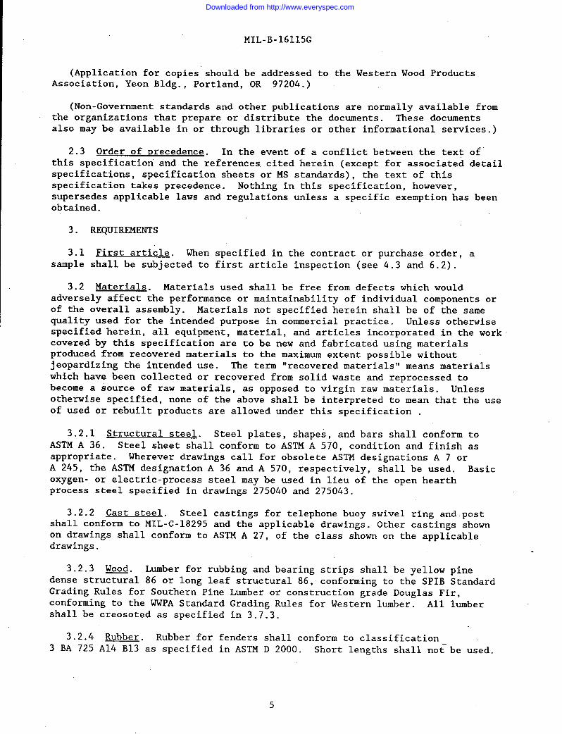
3.2 Materials. Materials used shall be free from defects which wouldadversely affect the performance or maintainability of individual components orof the overall assembly. Materials not specified herein shall be of the samequality used for the intended purpose in commercial practice. Unless otherwisespecified herein, all equipment, material, and articles incorporated in the workcovered by this specification are to be new and fabricated using materialsproduced from recovered materials to the maximum extent possible withoutjeopardizing the intended use. The term “recovered materials” means materialswhich have been collected or recovered from solid waste and reprocessed tobecome a source of raw materials, as opposed to virgin raw materials. Unlessotherwise specified, none of the above shall be interpreted to mean that the useof used or rebuilt products are allowed under this specification .
3.2.1 Structural steel. Steel plates, shapes, and bars shall conform toASTM A 36. Steel sheet shall conform to ASTM A 570, condition and finish asappropriate. Wherever drawings call for obsolete ASTM designations A 7 orA 245, the ASTM designation A 36 and A 570, respectively, shall be used. Basicoxygen- or electric-process steel may be used in lieu of the open hearthprocess steel specified in drawings 275040 and 275043.
3.2.2 Cast steel. Steel castings for telephone buoy swivel ring and postshall conform to MIL-C-18295 and the applicable drawings. Other castings shownon drawings shall conform to ASTM A 27, of the class shown on the applicabledrawings.
3.2.3 Wood Lumber for rubbing and bearing strips shall be yellow pinedense stru~al 86 or long leaf structural 86, conforming to the SPIB StandardGrading Rules for Southern Pine Lumber or construction grade Douglas Fir,conforming to the WWPA Standard Grading Rules for Western lumber. All lumbershall be creosoted as specified in 3.7.3.
3.2.4 Rubber. Rubber for fenders shall conform to classification3 BA 725 A14 B13 as specified in ASTM D 2000. Short lengths shall no~be used.
Downloaded from http://www.everyspec.com
MIL-B-16115G
3.3 Construction.
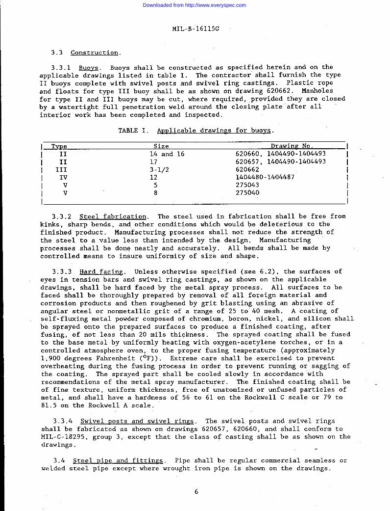
3.3.1 Buoys. Buoys shall be constructed as specified herein and on theapplicable drawings listed in table I. The contractor shall furnish the typeII buoys complete with swivel posts and swivel ring castings. Plastic ropeand floats for type 111 buoy shall be as shown on drawing 620662. Manholesfor type II and III buoys may be cut, where required, ,provided they are closedby a watertight full penetration weld around the closing plate ”after all ““interior work has been completed and inspected.
TABLE I. Amlicable drawinps for buovs.
I Tme Size Drawing No. 1.I II 14 and 16 620660, 1404490-1404493 II 11 17 620657, 1404490-1404493 II III 3-1/2 620662 II IV 12 1404480-1404487 IIv 5 275043 IIv 8 275040 II I
3.3.2 Steel fabrication. The steel used in fabrication shall be free fromkinks, sharp bends, and other conditions which would be deleterious to thefinished product. Manufacturing processes shall not reduce the strength ofthe steel to a value less than intended by the design. Manufacturingprocesses shall be done neatly and accurately. All bends shall be made bycontrolled means to insure uniformity of size and shape.
3.3.3 Hard facing. Unless otherwise specified (see 6.2), the surfaces ofeyes in tension bars and swivel ring castings, as shown on the applicabledrawings, shall be hard faced by the metal spray process. All surfaces to befaced shall be thoroughly prepared by removal of all foreign material andcorrosion products and then roughened by grit blasting using an abrasive ofangular steel or nonmetallic grit of a range of 25 to”40 mesh. A coating ofself-fluxing metal powder composed of chromium, boron, nickel, and silicon shallbe sprayed onto the prepared surfaces to produce a finished coating, afterfusing, of not less than 20 roils thickness. The sprayed coating shall be fusedto the base metal by uniformly heating with oxygen-acetylene torches, or in acontrolled atmosphere oven, to the proper fusing temperature (approximately1,900 degrees Fahrenheit (° F)). Extreme care shall be exercised to preventoverheating during the fusing process in order to prevent running or sagging ofthe coating. The sprayed part shall be cooled slowly in accordance withrecommendations of the metal spray manufacturer. The finished coating shall be -of fine texture, uniform thickness, free of anatomized or unfused particles ofmetal, and shall have a hardness of 56 to 61 on the Rockwell C scale or 79 to81.5 on the Rockwell A scale.
I3.3.4 Swivel ~osts and swivel rings. The swivel posts and swivel rings
shall be fabricated as shown on drawings 620657, 620660, and shall conform toMIL-C-18295, group 3, except that the class of casting shall be as shown on thedrawings.
3.4 Steel Qipe and fittiruzs. Pipe shall be regular commercial seamless orwelded steel pipe except where wrought iron pipe is shown on the drawings.
I 6
Downloaded from http://www.everyspec.com
MIL-B-16115G
Pipe shall be of the size, schedule, and wall thickness shown. Pipe fittingsshall be standard steel and cast iron as shown.
3.5 Fasteners. Studs, nuts, bolts, wood screws, and cap screws shall beof the characteristics, dimensions, and quantities as shown on the drawings.Steel fasteners, other than stainless steel, shall be zinc coated inconformance with ASTM A 123.
3.5.1 Bolts and nuts. Bolts and nuts shall conform to the requirements forregular hexagon, bolts and nuts of ANSI B18.2.1 and B18.2.2. Material shall betype 316 stainless steel.
3.5.2 Cap screws. Cap screws shall conform to the requirements for hexagonhead cap screws of ANSI B18.6.2. Material shall be type 316 stainless steel.
3.5.3 Wood screws. Wood screws shall conform to the requirements forslotted and recessed wood screws of ANSI B18.6.1. Material shall be brass.
3.5.4 Washers. Circular washers shall be flat,the requirements for type A washers as specified inshall be type 316 stainless steel.
3.6 Ti~htness. Type II and III buoys shall not
smooth and shall conform toANSI B18.22.1. Material
leak when tested by air.orhydrostatic pressure in accordance with 4.4.1 or 4.4.2, the method of testing tobe determined by the manufacturer. When tested hydrostatically, the buoys, andindividual compartments of buoys, shall withstand an internal hydrostaticpressure of 5 pounds per square inch (lb/sq-in), maintained for a period of notless than 15 minutes, without leakage, joint failure, or abnormal bulging ofplates. Type IV and V buoys shall be tested as specified on the drawings.
3.7 Treatment and Dainting.
3.7.1 Metal surfaces. After each buoy has passed all tests as specified,and before installation of fenders, rubbing and bearing strips, the exteriormetal surfaces of all buoys, tension bars, and swivel posts, except threadedsurfaces, shall be cleaned, treated, and painted in accordance with MIL-T-704,Type B, except that, finish paint shall conform to MIL-P-24441. Unlessotherwise specified (see 6.2), the finish color shall be lusterless black NO.37038 of FED-STD-595. In addition, the interior surfaces of Type IV and V buoysshall be cleaned, treated, and painted in accordance with MIL-T-704, Type C,except that the finish coat of Type IV shall be in accordance with TT-E-522,Type I.
3.7.2 Threaded surfaces..
The threaded surfaces of all fasteners in tappedholes, and all pipe plugs installed prior to and after testing, shall be coatedwith a thick mixture of red and white lead in linseed oil. As an optionthreaded surfaces can be protected with plastic thread protectors.
3.7.3 Wood treatment. All wood shall be pressure treated with creosote to anet retention of 20 pounds (lb) in accordance with AWPA C2. All treated lumber,cut or bored after treatment, shall have the cut surfaces coated with greosotein accordance with AWPA M4.
Downloaded from http://www.everyspec.com
MIL-B-16115G
3.8 Identification marking. The equipment shall be marked foridentification in accordance with MIL-STD-130. Unless otherwise specified onthe drawings, marking shall be l/8-incliraised letters l-inch high located onthe buoys under railing-for type I and II buoys or as shown on the applicabledrawing. The legend shall include size of’buoy, weight in lb, and year ofmanufacture.
I 3.9 Workmanship.-.
3.9.1 Steel fabrication. The steel used in fabr~cation shall be free fromkinks, sharp bends, and other conditions which would be deleterious to thefinished product. Manufacturing processes shall not reduce the strength of thesteel to a value less than intended by the design. Manufacturing processesshall be done neatly and accurately. All bends shall be made by controlledmeans to insure uniformity of size and shape.
3.9.2 Bolted connections. Bolt holes shall be accurately punched or drilledand shall have the burrs removed. Washers or lockwashers shall be provided inaccordance with good commercial practice, and all bolts, nuts, and screws shallbe tight.
3.9.3 Welding. Surfaces to be welded shall be free from foreign matterwhich would be injurious to the weld. Welding shall’conform to AWS D1.1. Spot,tack, or intermittent welds for strength will not be permitted. All weldingshall be performed by welders qualified as specified herein. Qualification ofwelders and duration of qualification period shall be in accordance with therequirements of AWS B2.1.
3.9.4 Wood fabrication. Wood bearing and rubbing strips shall be neatly andaccurately cut, contoured, finished, and drilled as shown, and shall fit snuglyto the buoy without forcing.
3.10 Servicing and restoration. Each unit tested shall be serviced andrestored to a service condition equal to the original condition of the unit,neglecting nominal wear incurred during the tests. The restoration shallinclude paint touch up or repainting, as required for delivery.
4. QUALITY ASSUMNCE PROVISIONS
4.1 Res~onsibilitv for ins~ection. Unless otherwise specified in thecontract or purchase order, the contractor is responsible for the performance ofall inspection requirements (examinations and tests) as specified herein.Except as otherwise specified in the contract or purchase order, the contractor .may use his own or any other facilities suitable for the performance of theinspection requirements specified herein, unless disapproved by the Government.The Government reserves the right to perform any of the inspections set forth inthe specification where such inspections are deemed necessary to ensure suppliesand services conform to prescribed requirements.
4.1.1 Res~onsibilitv for compliance. All items must meet all requirementsof sections 3 and 5. The inspection set forth in this specification shallbecome a part of the contractor’s overall inspection system or quality program.The absence of any inspection requirements in the specification shall notrelieve the contractor of the responsibility of ensuring that all products or
8
Downloaded from http://www.everyspec.com
MIL-B-16115G
supplies submitted to the Government for acceptance comply withof the contract. Sampling inspection, as part of manufacturing
all requirementsoperations, is
an acceptable practice to ascertain conformance to requirements, however, thisdoes not authorize submission of known defective material, either indicated oractual, nor does it commit the Government to accept defective material.
4.1.2 Component and material ins~ection. Components and materials shall beinspected in accordance with all the requirements” specified herein and in ““applicable referenced documents.
4.2 Classification of inspections. The inspection”requirements specifiedherein are classified as follows:
First article inspection (see 4.2.1).:: Quality conformance inspection (see 4.2.2).
4.2.1 First article inspection. When specified (see 6.3), first articleinspection shall be performed on one buoy. This inspection shall include theexamination of 4.3 and the tests of 4.4. The first article shall be the firstbuoy produced prior to initiation of the production items.
4.2.2 Oualitv conformance inspection. The quality conformance inspectionshall include the examination of 4.3, the tests of 4.4, and the packaginginspection of 4.5. This inspection shall be performed on the samples selectedin accordance with 4.3.
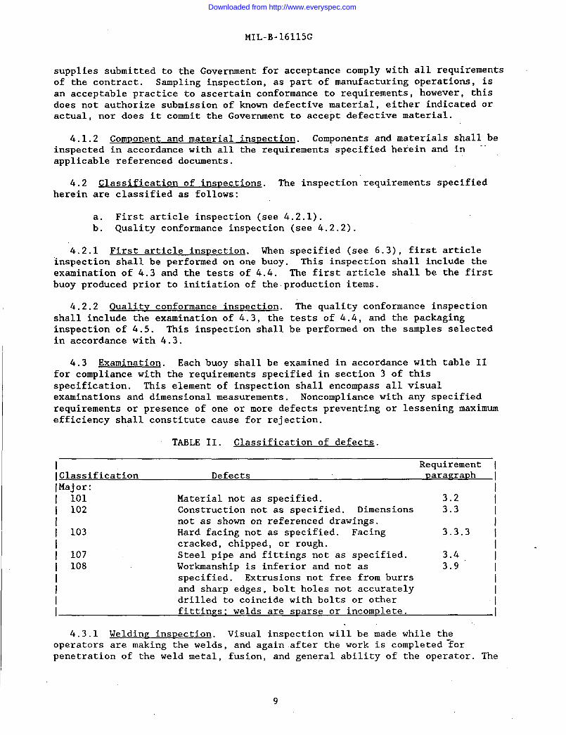
4.3 Examination. Each buoy shall be examined in accordance with table IIfor compliance with the requirements specified in section 3 of thisspecification. This element of inspection shall encompass all visualexaminations and dimensional measurements. Noncompliance with any specifiedrequirements or presence of one or more defects preventing or lessening maximumefficiency shall constitute cause for rejection.
TABLE II. Classification of defects.
Requirement [Classification Defects DaraKraDh IMajor: I
101 Material not as specified. 3.2 I102 Construction not as specified. Dimensions 3.3
not as shown on referenced drawings. /103 Hard facing not as specified. Facing 3.3.3 I
I cracked, chipped, or rough. 1.I 107 Steel pipe and fittings not as specified. 3.4 !I 108 Workmanship is inferior and not as 3.9 ‘I specified. Extrusions not free from burrs II and sharp edges, bolt holes not accuratelyI drilled to coincide with bolts or other /I fittinrs; welds are sparse or incom~lete. I
4.3.1 Weldin~ inspection. Visual inspection will be made while theoperators are making the welds, and again after the work is completed-forpenetration of the weld metal, fusion, and general ability of the operator. The
9
Downloaded from http://www.everyspec.com
MIL-B-16115G
inspector will pay particular attention to surface cracking, surface porosity,surface slag inclusions, undercut, overlap, and size of welds.
4.4 Test Tests for type IV and V buoys shall be as shown on the drawings.—.For type I, II, and III buoys, before painting the first article shall besubject to the test of either 4.4.1 or 4.4.2 and the test of 4.4.3.
4.4.1 Pneumatic test. Each buoy having one or more compartments, shall-betested for tightness of joints by the application of air pressure of not lessthan 5 lb\sq-in for a minimum period of 30 minutes. mile the buoy is underpressure, a soapsuds solution shall be applied externally to reveal any leaks oras an option, the pressurized buoy shall be given full immersion to detect anyleaks.
4.4.2 Hydrostatic test. After completion of all welding, the buoy shall besubjected to a hydrostatic test of not less than the specified pressure (see3.6) maintained for a period of 15 minutes. Any joint failure or leaks shall because for rejection. The water used for hydrostatic testing shall be made rustinhibiting by the addition of sodium bichromate at a concentration of 1/2percent by weight. After completion of the test, each buoy shall be thoroughlydrained to remove all liquids.
4.4.3 Radio~ra~hic test.drawings and required herein,of defects which would affectrejection.
4.5 PackazinE inspection.of the buoys and tension barsrequirements in section 5.
5. PACKAGING
5.1 Preservation, ~ackin~
Radiographic tests of parts, where shown on theshall be in accordance with MIL-STD-271; evidencethe strength of these parts shall be cause for
The preservation-packaging, packing, and markingshall be inspected to verify conformance to
and marking. Each buoy shall be preserved,
the
packedand marked in accordance with ASTM D 395i. Packing shall be acceptable tocommercial carriers and comply with Uniform Freight Classification Rules orNational Motor Freight Classification Rules as applicable.
6. NOTES
(This section contains information of a general or explanatory nature thatmay be helpful, but is not mandatory.)
6.1 Intended use. Type 11 buoys are used in standard fleet mooringassemblies . Type III buoys are used for marking the ends of submerged fueltransfer lines, marking centerline of tanker berth, and for small craftmoorings, as appropriate for the size. Type IV and V buoys are used for mooringand flotation.
6.2 Acquisition reauirements. Acquisition documents must specify thefollowing:
Title, number, and date of this specification.:: Type and size buoy required (see 1.2).
10
Downloaded from http://www.everyspec.com
MIL-B-16115G
c.
d.
e.
f.
g.
Issue of DODISS to be cited in the solicitation, and if required,the specific issue of individual documents referenced(see 2.1.1 and 2.2).When first article is required for inspection and approval(see 3.1, 4.2.1, and 6.3).When hard surfacing shall be applied by methods other than metalspraying (see 3.3.3 and 6.4).When finish paint shall be other than as specified (see 3.7.1). -When color of finish paint shall be other than as specified(see 3.7.1).
6.3 First article. When a first article inspection is required, the itemwill be tested and should be a first production item as specified in 4.2.1. Thefirst article should consist of one unit. The contracting officer shouldinclude specific instructions in acquisition documents regarding arrangementsfor examination, test, and approval of the first article.
6.4 Hardfacinz alternates. Hard facings normally are applied by the gaswelding, metal arc welding, atomic-hydrogen arc welding, or spray weldingprocess. The advantages of spray welding are mainly economic. First, it savesalloy by achieving a more closely controlled deposit, and second, the cost offinishing the more uniform deposit is less.
6.5
6.6
Subject term (key word) listing.
FendersFleet mooringsManholesRubbing and bearing stripsSwivel postsSwivel ringTension Bars
Changes from previous issue. Marginal notations are not used in thisrevision to identify changes with respect to the previous issue due to theextensiveness of the changes.
Custodian: Preparing activity:Navy - YD Navy - YD
Review activity: (Project 2050-0031)Navy - OS
User activity:Army - ME
11
Downloaded from http://www.everyspec.com

.... . . .,
STANDARDIZATION DOCUMENT IMPROVEMENT PROPOSAL
INSTRUCTIONS
1. The preparing activity must complete blocks 1, 2, 3, and 8. Inblock1,boththedocumentnumberandrevisionletter should be given.
2. The submitter of this form must complete blocks 4,5,6, and 7.
3. The preparing activity must provide a reply within 30 days from receipt of the form.
NOTE: This form may not be usedto request copies of documents, nor to request waivers, or clarification ofrequirements on current contracts. Comments submitted on this form do not constitute or imply authorization towaive any portion of the referenced document(s) or to amend contractual requirements.
2. DOCUMENT DATE (YYMMDOJ
, DOCUMENT TITLE
BUOYS; MOORING AND MARKER.
NATURE OF CHANGE (/dentify paragraph number and include proposed rewrite, if possible. Artach extra sheers as needed.)
L REASON FOR RECOMMENDATION
DO Form 1426, OCT 89 Previous editions are obfolete. 19!Y290
Downloaded from http://www.everyspec.com
Related Documents