Bulletin 140U Molded Case Circuit Breakers 38 Overview Product Line Overview Bulletin 140U Molded Case Circuit Breakers • 15…1200 A Molded Case Circuit Breakers Thermal-Magnetic 15…800 A Electronic 70…1200 A -LS — Long Time/Short Time -LSI — Long Time/Short Time/High Instantaneous -LSG — Long Time/Short Time/Ground Fault -LSIG — Long Time/Short Time/High Instantaneous/Ground Fault Molded Case Switches 125…1200 A • Factory- or field-installed accessories • Flex cable operating mechanisms • Rotary variable-depth operating mechanisms • High interrupting ratings in compact dimensions • Globally rated and approved product line for worldwide application Product Selection 125 A H-Frame .............. 41 250 A J-Frame ............... 45 400 A K-Frame .............. 49 600 A Q-Frame .............. 53 800 A M-Frame .............. 57 1200 A N-Frame ............ 61 Conformity to Standards UL 489 CSA 22.2, No. 5 IEC 60947-2 Approvals UL Listed CSA Certified CE KEMA-KEUR Frame Reference H-Frame J-Frame K-Frame Q-Frame M-Frame N-Frame Max. Current I n 125 A 250 A 400 A 600 A 800 A 1200 A Current Range 15…125 A 70…250 A 100…400 A 300…600 A 300…800 A 600…1200 A Thermal Magnetic ✓ ✓ ✓ ✓ ✓ — Electronic: — ✓ ✓ ✓ ✓ ✓ LS — ✓ ✓ ✓ ✓ ✓ LSI — ✓ ✓ ✓ ✓ ✓ LSG — ✓ ✓ ✓ ✓ ✓ LSIG — ✓ ✓ ✓ ✓ ✓ Interrupting Ratings: 380…415V (I cu ) 25 40 70 25 40 70 40 65 100 45 70 50 70 50 70 100 480V 25 35 65 25 35 65 35 65 100 35 65 50 65 50 65 100 600V 18 22 25 18 18 25 25 35 50 25 35 25 35 25 35 50 690V (I cu ) 3 4 6 6 6 7 10 13 18 20 25 20 25 20 25 30 Molded Case Switches ✓ ✓ ✓ ✓ ✓ ✓ Flex Cable Operators ✓ ✓ ✓ ✓ ✓ ✓ Rotary Operators ✓ ✓ ✓ ✓ ✓ ✓ Internal Control Modules (Field installed) ✓ ✓ ✓ ✓ ✓ ✓ Standards Compliance UL 498 ✓ ✓ ✓ ✓ ✓ ✓ CSA 22.2, No. 5 ✓ ✓ ✓ ✓ ✓ ✓ IEC 60947-2 ✓ ✓ — ✓ ✓ ✓ CE ✓ ✓ — ✓ ✓ ✓ KEMA-KEUR ✓ ✓ ✓ ✓ ✓ ✓

Welcome message from author
This document is posted to help you gain knowledge. Please leave a comment to let me know what you think about it! Share it to your friends and learn new things together.
Transcript
Bulletin 140U
Molded Case Circuit BreakersOverviewProduct Line Overview
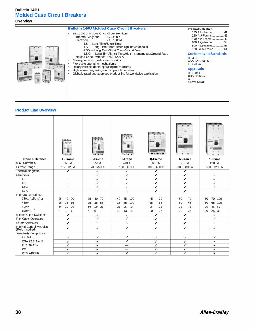
Bulletin 140U Molded Case Circuit Breakers• 15…1200 A Molded Case Circuit Breakers
Thermal-Magnetic 15…800 AElectronic 70…1200 A
-LS — Long Time/Short Time-LSI — Long Time/Short Time/High Instantaneous-LSG — Long Time/Short Time/Ground Fault-LSIG — Long Time/Short Time/High Instantaneous/Ground Fault
Molded Case Switches 125…1200 A• Factory- or field-installed accessories• Flex cable operating mechanisms• Rotary variable-depth operating mechanisms• High interrupting ratings in compact dimensions• Globally rated and approved product line for worldwide application
Product Selection125 A H-Frame .............. 41250 A J-Frame ............... 45400 A K-Frame .............. 49600 A Q-Frame .............. 53800 A M-Frame.............. 571200 A N-Frame ............ 61
Conformity to StandardsUL 489CSA 22.2, No. 5IEC 60947-2
ApprovalsUL ListedCSA CertifiedCEKEMA-KEUR
Frame Reference H-Frame J-Frame K-Frame Q-Frame M-Frame N-FrameMax. Current In 125 A 250 A 400 A 600 A 800 A 1200 ACurrent Range 15…125 A 70…250 A 100…400 A 300…600 A 300…800 A 600…1200 AThermal Magnetic ✓ ✓ ✓ ✓ ✓ —Electronic: — ✓ ✓ ✓ ✓ ✓
LS — ✓ ✓ ✓ ✓ ✓
LSI — ✓ ✓ ✓ ✓ ✓
LSG — ✓ ✓ ✓ ✓ ✓
LSIG — ✓ ✓ ✓ ✓ ✓
Interrupting Ratings:380…415V (Icu) 25 40 70 25 40 70 40 65 100 45 70 50 70 50 70 100480V 25 35 65 25 35 65 35 65 100 35 65 50 65 50 65 100600V 18 22 25 18 18 25 25 35 50 25 35 25 35 25 35 50690V (Icu) 3 4 6 6 6 7 10 13 18 20 25 20 25 20 25 30
Molded Case Switches ✓ ✓ ✓ ✓ ✓ ✓
Flex Cable Operators ✓ ✓ ✓ ✓ ✓ ✓
Rotary Operators ✓ ✓ ✓ ✓ ✓ ✓
Internal Control Modules (Field installed) ✓ ✓ ✓ ✓ ✓ ✓
Standards ComplianceUL 498 ✓ ✓ ✓ ✓ ✓ ✓
CSA 22.2, No. 5 ✓ ✓ ✓ ✓ ✓ ✓
IEC 60947-2 ✓ ✓ — ✓ ✓ ✓
CE ✓ ✓ — ✓ ✓ ✓
KEMA-KEUR ✓ ✓ ✓ ✓ ✓ ✓
38
Bulletin 140U
Molded Case Circuit BreakersCatalog Number Explanation
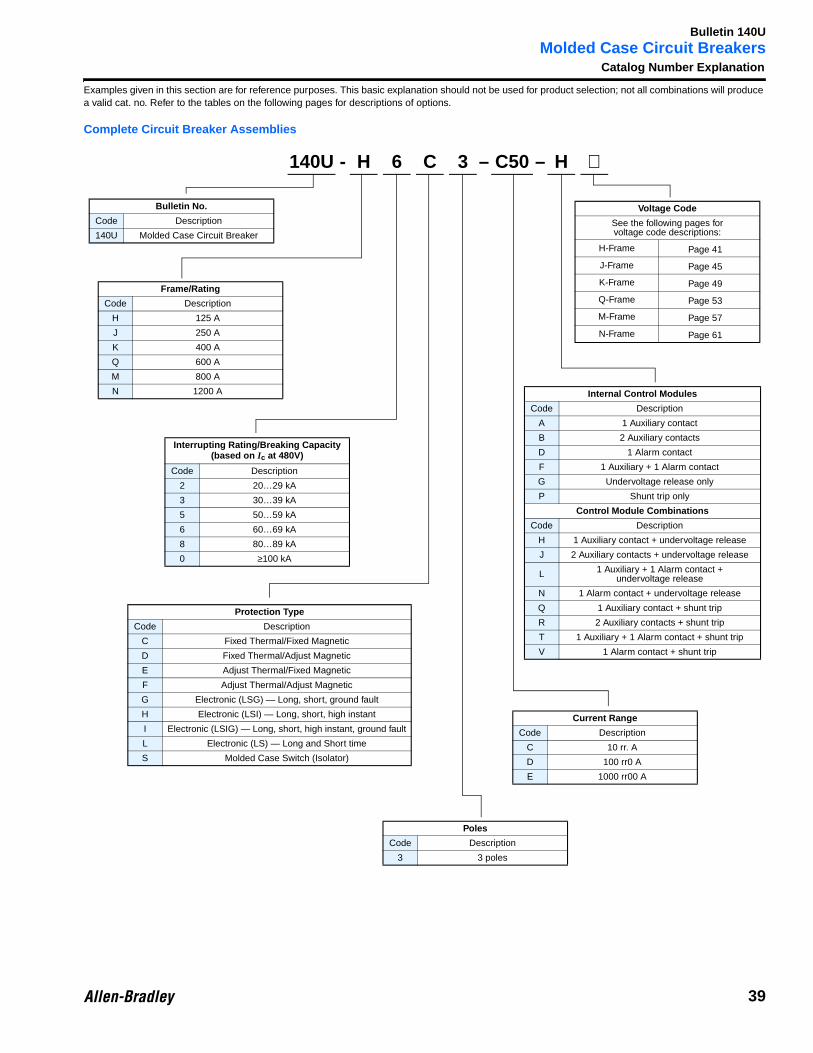
Examples given in this section are for reference purposes. This basic explanation should not be used for product selection; not all combinations will produce a valid cat. no. Refer to the tables on the following pages for descriptions of options.
Complete Circuit Breaker Assemblies
Bulletin No.
Code Description
140U Molded Case Circuit Breaker
140U - H 6 C 3 – C50 – H ⊗
Frame/Rating
Code Description
H 125 A
J 250 A
K 400 A
Q 600 A
M 800 A
N 1200 A
Interrupting Rating/Breaking Capacity (based on Ic at 480V)
Code Description
2 20…29 kA
3 30…39 kA
5 50…59 kA
6 60…69 kA
8 80…89 kA
0 ≥100 kA
Protection Type
Code Description
C Fixed Thermal/Fixed Magnetic
D Fixed Thermal/Adjust Magnetic
E Adjust Thermal/Fixed Magnetic
F Adjust Thermal/Adjust Magnetic
G Electronic (LSG) — Long, short, ground fault
H Electronic (LSI) — Long, short, high instant
I Electronic (LSIG) — Long, short, high instant, ground fault
L Electronic (LS) — Long and Short time
S Molded Case Switch (Isolator)
Poles
Code Description
3 3 poles
Current Range
Code Description
C 10 rr. A
D 100 rr0 A
E 1000 rr00 A
Internal Control Modules
Code Description
A 1 Auxiliary contact
B 2 Auxiliary contacts
D 1 Alarm contact
F 1 Auxiliary + 1 Alarm contact
G Undervoltage release only
P Shunt trip only
Control Module Combinations
Code Description
H 1 Auxiliary contact + undervoltage release
J 2 Auxiliary contacts + undervoltage release
L 1 Auxiliary + 1 Alarm contact + undervoltage release
N 1 Alarm contact + undervoltage release
Q 1 Auxiliary contact + shunt trip
R 2 Auxiliary contacts + shunt trip
T 1 Auxiliary + 1 Alarm contact + shunt trip
V 1 Alarm contact + shunt trip
Voltage Code
See the following pages forvoltage code descriptions:
H-Frame Page 41
J-Frame Page 45
K-Frame Page 49
Q-Frame Page 53
M-Frame Page 57
N-Frame Page 61
39
Bulletin 140U
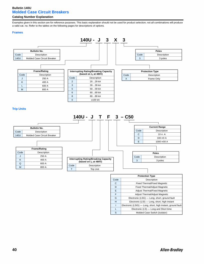
Molded Case Circuit BreakersCatalog Number ExplanationExamples given in this section are for reference purposes. This basic explanation should not be used for product selection; not all combinations will produce a valid cat. no. Refer to the tables on the following pages for descriptions of options.
Frames
Trip Units
Bulletin No.
Code Description
140U Molded Case Circuit Breaker
140U - J 3 X 3
Frame/Rating
Code Description
J 250 A
K 400 A
L 600 A
M 800 A
Interrupting Rating/Breaking Capacity (based on Ic at 480V)
Code Description
2 20…29 kA
3 30…39 kA
5 50…59 kA
6 60…69 kA
8 80…89 kA
0 ≥100 kA
Protection Type
Code Description
X Frame Only
Poles
Code Description
3 3 poles
Bulletin No.
Code Description
140U Molded Case Circuit Breaker
140U - J T F 3 – C50
Frame/Rating
Code Description
J 250 A
K 400 A
Q 600 A
M 800 A
Interrupting Rating/Breaking Capacity (based on Ic at 480V)
Code Description
T Trip Unit
Protection Type
Code Description
C Fixed Thermal/Fixed Magnetic
D Fixed Thermal/Adjust Magnetic
E Adjust Thermal/Fixed Magnetic
F Adjust Thermal/Adjust Magnetic
G Electronic (LSG) — Long, short, ground fault
H Electronic (LSI) — Long, short, high instant
I Electronic (LSIG) — Long, short, high instant, ground fault
L Electronic (LS) — Long and Short time
S Molded Case Switch (isolator)
Poles
Code Description
3 3 poles
Current Range
Code Description
C 10 rr. A
D 100 rr0 A
E 1000 rr00 A
40
Bulletin 140U
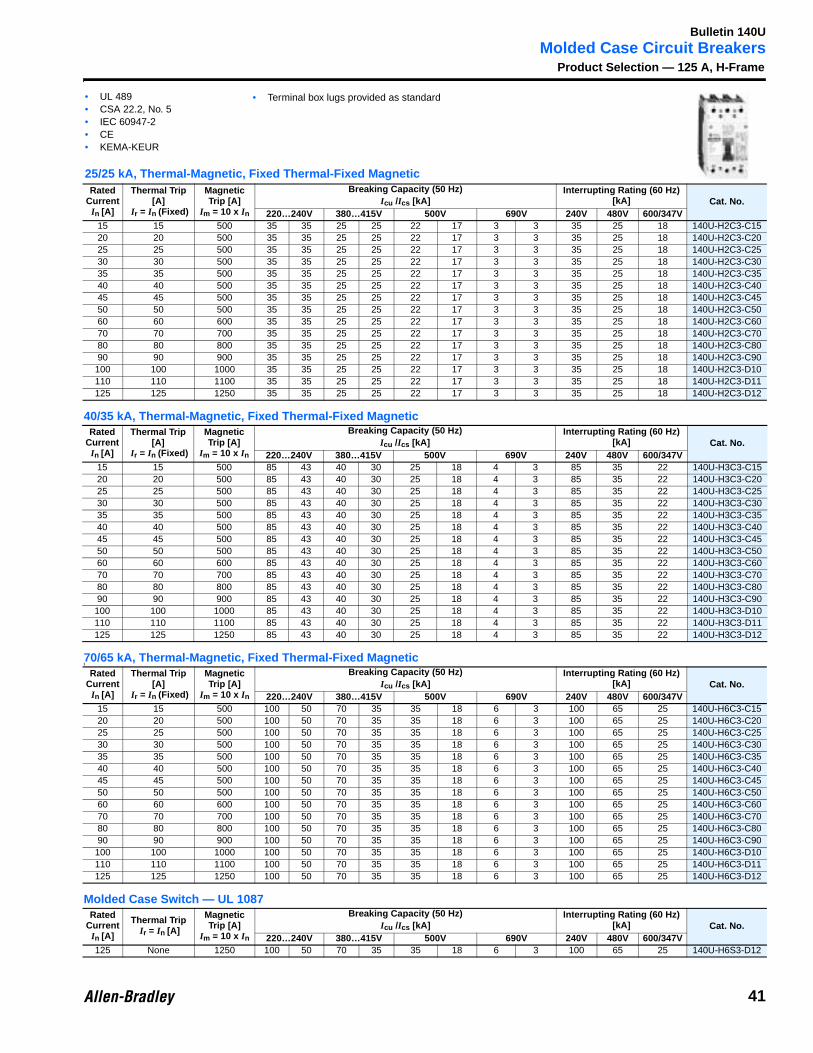
Molded Case Circuit BreakersProduct Selection — 125 A, H-Frame
40/35 kA, Thermal-Magnetic, Fixed Thermal-Fixed Magnetic
70/65 kA, Thermal-Magnetic, Fixed Thermal-Fixed Magneticl
Molded Case Switch — UL 1087
Rated Current
In [A]
Thermal Trip [A]
Ir = In (Fixed)
Magnetic Trip [A]
Im = 10 x In
Breaking Capacity (50 Hz) Interrupting Rating (60 Hz)[kA] Cat. No.Icu /Ics [kA]
220…240V 380…415V 500V 690V 240V 480V 600/347V15 15 500 35 35 25 25 22 17 3 3 35 25 18 140U-H2C3-C1520 20 500 35 35 25 25 22 17 3 3 35 25 18 140U-H2C3-C2025 25 500 35 35 25 25 22 17 3 3 35 25 18 140U-H2C3-C2530 30 500 35 35 25 25 22 17 3 3 35 25 18 140U-H2C3-C3035 35 500 35 35 25 25 22 17 3 3 35 25 18 140U-H2C3-C3540 40 500 35 35 25 25 22 17 3 3 35 25 18 140U-H2C3-C4045 45 500 35 35 25 25 22 17 3 3 35 25 18 140U-H2C3-C4550 50 500 35 35 25 25 22 17 3 3 35 25 18 140U-H2C3-C5060 60 600 35 35 25 25 22 17 3 3 35 25 18 140U-H2C3-C6070 70 700 35 35 25 25 22 17 3 3 35 25 18 140U-H2C3-C7080 80 800 35 35 25 25 22 17 3 3 35 25 18 140U-H2C3-C8090 90 900 35 35 25 25 22 17 3 3 35 25 18 140U-H2C3-C90
100 100 1000 35 35 25 25 22 17 3 3 35 25 18 140U-H2C3-D10110 110 1100 35 35 25 25 22 17 3 3 35 25 18 140U-H2C3-D11125 125 1250 35 35 25 25 22 17 3 3 35 25 18 140U-H2C3-D12
Rated Current
In [A]
Thermal Trip [A]
Ir = In (Fixed)
Magnetic Trip [A]
Im = 10 x In
Breaking Capacity (50 Hz) Interrupting Rating (60 Hz)[kA] Cat. No.Icu /Ics [kA]
220…240V 380…415V 500V 690V 240V 480V 600/347V15 15 500 85 43 40 30 25 18 4 3 85 35 22 140U-H3C3-C1520 20 500 85 43 40 30 25 18 4 3 85 35 22 140U-H3C3-C2025 25 500 85 43 40 30 25 18 4 3 85 35 22 140U-H3C3-C2530 30 500 85 43 40 30 25 18 4 3 85 35 22 140U-H3C3-C3035 35 500 85 43 40 30 25 18 4 3 85 35 22 140U-H3C3-C3540 40 500 85 43 40 30 25 18 4 3 85 35 22 140U-H3C3-C4045 45 500 85 43 40 30 25 18 4 3 85 35 22 140U-H3C3-C4550 50 500 85 43 40 30 25 18 4 3 85 35 22 140U-H3C3-C5060 60 600 85 43 40 30 25 18 4 3 85 35 22 140U-H3C3-C6070 70 700 85 43 40 30 25 18 4 3 85 35 22 140U-H3C3-C7080 80 800 85 43 40 30 25 18 4 3 85 35 22 140U-H3C3-C8090 90 900 85 43 40 30 25 18 4 3 85 35 22 140U-H3C3-C90100 100 1000 85 43 40 30 25 18 4 3 85 35 22 140U-H3C3-D10110 110 1100 85 43 40 30 25 18 4 3 85 35 22 140U-H3C3-D11125 125 1250 85 43 40 30 25 18 4 3 85 35 22 140U-H3C3-D12
Rated Current
In [A]
Thermal Trip [A]
Ir = In (Fixed)
Magnetic Trip [A]
Im = 10 x In
Breaking Capacity (50 Hz) Interrupting Rating (60 Hz)[kA] Cat. No.Icu /Ics [kA]
220…240V 380…415V 500V 690V 240V 480V 600/347V15 15 500 100 50 70 35 35 18 6 3 100 65 25 140U-H6C3-C1520 20 500 100 50 70 35 35 18 6 3 100 65 25 140U-H6C3-C2025 25 500 100 50 70 35 35 18 6 3 100 65 25 140U-H6C3-C2530 30 500 100 50 70 35 35 18 6 3 100 65 25 140U-H6C3-C3035 35 500 100 50 70 35 35 18 6 3 100 65 25 140U-H6C3-C3540 40 500 100 50 70 35 35 18 6 3 100 65 25 140U-H6C3-C4045 45 500 100 50 70 35 35 18 6 3 100 65 25 140U-H6C3-C4550 50 500 100 50 70 35 35 18 6 3 100 65 25 140U-H6C3-C5060 60 600 100 50 70 35 35 18 6 3 100 65 25 140U-H6C3-C6070 70 700 100 50 70 35 35 18 6 3 100 65 25 140U-H6C3-C7080 80 800 100 50 70 35 35 18 6 3 100 65 25 140U-H6C3-C8090 90 900 100 50 70 35 35 18 6 3 100 65 25 140U-H6C3-C90
100 100 1000 100 50 70 35 35 18 6 3 100 65 25 140U-H6C3-D10110 110 1100 100 50 70 35 35 18 6 3 100 65 25 140U-H6C3-D11125 125 1250 100 50 70 35 35 18 6 3 100 65 25 140U-H6C3-D12
Rated Current
In [A]
Thermal Trip Ir = In [A]
Magnetic Trip [A]
Im = 10 x In
Breaking Capacity (50 Hz) Interrupting Rating (60 Hz)[kA] Cat. No.Icu /Ics [kA]
220…240V 380…415V 500V 690V 240V 480V 600/347V125 None 1250 100 50 70 35 35 18 6 3 100 65 25 140U-H6S3-D12
• UL 489• CSA 22.2, No. 5• IEC 60947-2• CE• KEMA-KEUR
25/25 kA, Thermal-Magnetic, Fixed Thermal-Fixed Magnetic
• Terminal box lugs provided as standard
41
Bulletin 140U
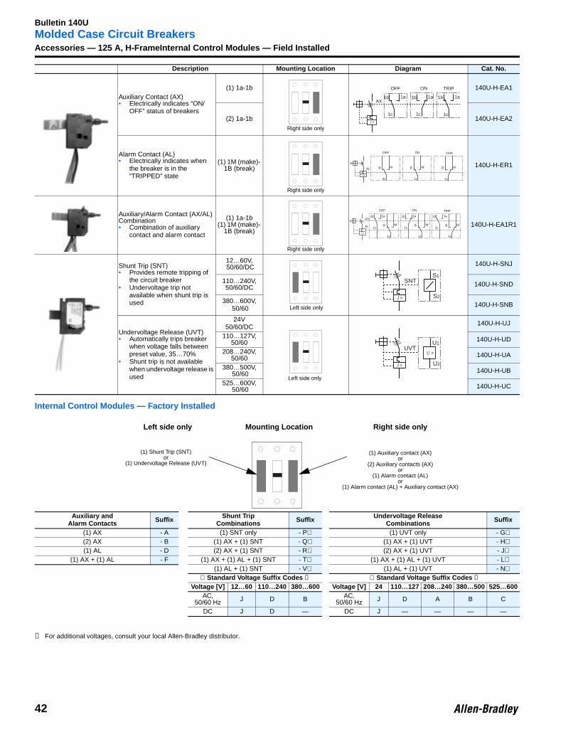
Molded Case Circuit BreakersAccessories — 125 A, H-FrameInternal Control Modules — Field InstalledInternal Control Modules — Factory Installed
➊ For additional voltages, consult your local Allen-Bradley distributor.
Description Mounting Location Diagram Cat. No.
Auxiliary Contact (AX)• Electrically indicates “ON/
OFF” status of breakers
(1) 1a-1b 140U-H-EA1
(2) 1a-1b 140U-H-EA2
Alarm Contact (AL)• Electrically indicates when
the breaker is in the “TRIPPED” state
(1) 1M (make)- 1B (break) 140U-H-ER1
Auxiliary/Alarm Contact (AX/AL) Combination• Combination of auxiliary
contact and alarm contact
(1) 1a-1b(1) 1M (make)-
1B (break)140U-H-EA1R1
Shunt Trip (SNT)• Provides remote tripping of
the circuit breaker• Undervoltage trip not
available when shunt trip is used
12…60V, 50/60/DC 140U-H-SNJ
110…240V, 50/60/DC 140U-H-SND
380…600V, 50/60 140U-H-SNB
Undervoltage Release (UVT)• Automatically trips breaker
when voltage falls between preset value, 35…70%
• Shunt trip is not available when undervoltage release is used
24V50/60/DC 140U-H-UJ
110…127V, 50/60 140U-H-UD
208…240V, 50/60 140U-H-UA
380…500V, 50/60 140U-H-UB
525…600V, 50/60 140U-H-UC
Auxiliary andAlarm Contacts Suffix Shunt Trip
Combinations Suffix Undervoltage ReleaseCombinations Suffix
(1) AX - A (1) SNT only - P⊗ (1) UVT only - G⊗(2) AX - B (1) AX + (1) SNT - Q⊗ (1) AX + (1) UVT - H⊗(1) AL - D (2) AX + (1) SNT - R⊗ (2) AX + (1) UVT - J⊗
(1) AX + (1) AL - F (1) AX + (1) AL + (1) SNT - T⊗ (1) AX + (1) AL + (1) UVT - L⊗(1) AL + (1) SNT - V⊗ (1) AL + (1) UVT - N⊗
⊗ Standard Voltage Suffix Codes ➊ ⊗ Standard Voltage Suffix Codes ➊Voltage [V] 12…60 110…240 380…600 Voltage [V] 24 110…127 208…240 380…500 525…600
AC, 50/60 Hz J D B AC,
50/60 Hz J D A B C
DC J D — DC J — — — —
Right side only
1b
1c
1a
I >
AX
ON
1b
1c
1a
OFF
1b
1c
1a
TRIP
Right side only
I >
ON
B
1c
M
OFF TRIP
AL B
1c
M B
1c
M
Right side only
1b
1c
1a
I >
AX
ON
B
1c
M
OFF TRIP
AL
1b
1c
1a
B
1c
M
1b
1c
1a
B
1c
M
Left side only
S1
I >
SNT
S2
Left side only
U1
I >
UVT
U2
U >
(1) Shunt Trip (SNT)or
(1) Undervoltage Release (UVT)
(1) Auxiliary contact (AX)or
(2) Auxiliary contacts (AX)or
(1) Alarm contact (AL)or
(1) Alarm contact (AL) + Auxiliary contact (AX)
Mounting LocationLeft side only Right side only
42
Bulletin 140U
Molded Case Circuit BreakersAccessories — 125 A, H-Frame, Continued
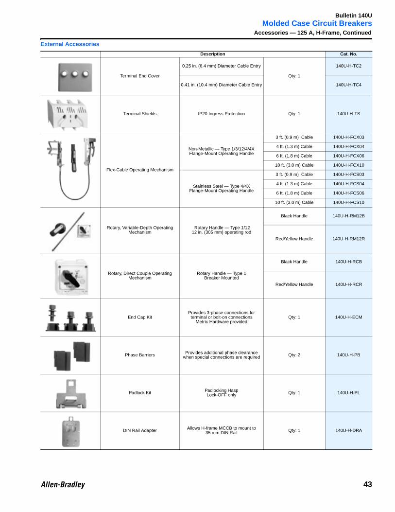
External Accessories
Description Cat. No.
Terminal End Cover
0.25 in. (6.4 mm) Diameter Cable Entry
Qty: 1
140U-H-TC2
0.41 in. (10.4 mm) Diameter Cable Entry 140U-H-TC4
Terminal Shields IP20 Ingress Protection Qty: 1 140U-H-TS
Flex-Cable Operating Mechanism
Non-Metallic — Type 1/3/12/4/4X Flange-Mount Operating Handle
3 ft. (0.9 m) Cable 140U-H-FCX03
4 ft. (1.3 m) Cable 140U-H-FCX04
6 ft. (1.8 m) Cable 140U-H-FCX06
10 ft. (3.0 m) Cable 140U-H-FCX10
Stainless Steel — Type 4/4X Flange-Mount Operating Handle
3 ft. (0.9 m) Cable 140U-H-FCS03
4 ft. (1.3 m) Cable 140U-H-FCS04
6 ft. (1.8 m) Cable 140U-H-FCS06
10 ft. (3.0 m) Cable 140U-H-FCS10
Rotary, Variable-Depth Operating Mechanism
Rotary Handle — Type 1/1212 in. (305 mm) operating rod
Black Handle 140U-H-RM12B
Red/Yellow Handle 140U-H-RM12R
Rotary, Direct Couple Operating Mechanism
Rotary Handle — Type 1 Breaker Mounted
Black Handle 140U-H-RCB
Red/Yellow Handle 140U-H-RCR
End Cap KitProvides 3-phase connections for terminal or bolt-on connections
Metric Hardware providedQty: 1 140U-H-ECM
Phase Barriers Provides additional phase clearance when special connections are required Qty: 2 140U-H-PB
Padlock Kit Padlocking HaspLock-OFF only Qty: 1 140U-H-PL
DIN Rail Adapter Allows H-frame MCCB to mount to 35 mm DIN Rail Qty: 1 140U-H-DRA
43
Bulletin 140U
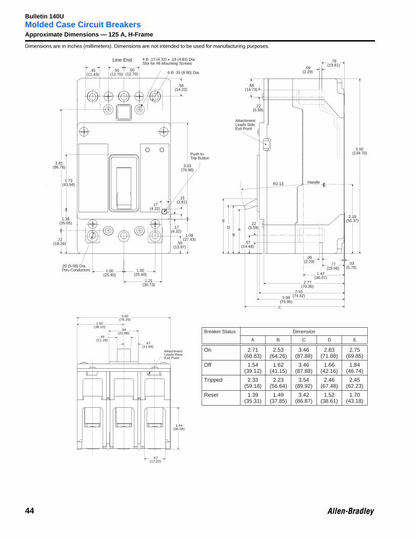
Molded Case Circuit BreakersApproximate Dimensions — 125 A, H-FrameDimensions are in inches (millimeters). Dimensions are not intended to be used for manufacturing purposes.
Line End
.45(11.43)
4 Ð .17 (4.32) x .19 (4.83) Dia.Slot for #6 Mounting Screws
6 Ð .35 (8.90) Dia.
.72(18.29)
1.38(35.05)
1.73(43.94)
3.03(76.96)
Push toTrip Button
.17(4.32)
.15(3.81)
.17(4.32)
1.08(27.43)
.55(13.97)
.20 (5.08) Dia.Thru Conductors 1.00
(25.40)1.21
(30.73)
1.00(25.40)
.50(12.70)
.50(12.70)
3.81(96.78)
.56(14.22)
Breaker Status Dimension
A B C D E
On 2.71(68.83)
2.53(64.26)
3.46(87.88)
2.83(71.88)
2.75(69.85)
Off 1.54(39.12)
1.62(41.15)
3.46(87.88)
1.66(42.16)
1.84(46.74)
Tripped 2.33(59.18)
2.23(56.64)
3.54(89.92)
2.46(67.48)
2.45(62.23)
Reset 1.39(35.31)
1.49(37.85)
3.42(86.87)
1.52(38.61)
1.70(43.18)
.78(19.81)
.09(2.29)
.22(5.59)
AttachmentLeads SideExit Point
5.50(139.70)
2.18(55.37)
Handle
.03(0.76)
.09(2.29)
.77(19.56)
1.42(36.07)
2.77(70.36)
2.93(74.42)2.99
(75.95)C
E
D
BA
.22(5.59)
.57(14.48)
R2.13
.58(14.73)
CL
.44(11.18)
1.50(38.10)
.47(11.94)
AttachmentLeads RearExit Point
.67(17.02)
1.44(36.58)
.94(23.88)
3.00(76.20)
44
Bulletin 140U
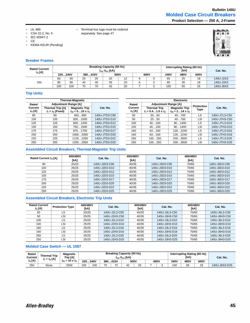
Molded Case Circuit BreakersProduct Selection — 250 A, J-Frame
Breaker Frames
Trip Units
Assembled Circuit Breakers, Thermal-Magnetic Trip Units
Assembled Circuit Breakers, Electronic Trip Units
Molded Case Switch — UL 1087
Rated Current In [A]
Breaking Capacity (50 Hz) Interrupting Rating (60 Hz) [kA] Cat. No.Icu /Ics [kA]
220…240V 380…415V 500V 690V 240V 480V 600V
25065 65 25 25 20 12 6 3 65 25 18 140U-J2X385 85 40 40 35 20 6 3 85 35 18 140U-J3X3
100 100 70 70 42 20 7 3 100 65 25 140U-J6X3
Thermal-Magnetic ElectronicRated
CurrentIn [A]
Adjustment Range [A]Cat. No.
Rated Current In [A]
Adjustment Range [A]Protection
Type Cat. No.Thermal Trip [A] Ir = In (Fixed)
Magnetic TripIm = 5…10 x In
Thermal TripIr = 0.4…1.0 x In
Magnetic TripIm = 2…14 x In
90 90 450…900 140U-JTD3-C90 50 20…50 40…700 LS 140U-JTL3-C50100 100 500…1000 140U-JTD3-D10 50 20…50 40…700 LSI 140U-JTH3-C50125 125 600…1250 140U-JTD3-D12 100 40…100 80…1400 LS 140U-JTL3-D10150 150 750…1500 140U-JTD3-D15 100 40…100 80…1400 LSI 140U-JTH3-D10175 175 875…1750 140U-JTD3-D17 160 63…160 126…2240 LS 140U-JTL3-D16200 200 1000…2000 140U-JTD3-D20 160 63…160 126…2240 LSI 140U-JTH3-D16225 225 1125…2250 140U-JTD3-D22 250 100…250 200…3500 LS 140U-JTL3-D25250 250 1250…2500 140U-JTD3-D25 250 100…250 200…3500 LSI 140U-JTH3-D25
Rated Current In [A]400/480V
Cat. No.400/480V
Cat. No.400/480V
Cat. No.[kA] [kA] [kA]
90 25/25 140U-J2D3-C90 40/35 140U-J3D3-C90 70/65 140U-J6D3-C90100 25/25 140U-J2D3-D10 40/35 140U-J3D3-D10 70/65 140U-J6D3-D10125 25/25 140U-J2D3-D12 40/35 140U-J3D3-D12 70/65 140U-J6D3-D12150 25/25 140U-J2D3-D15 40/35 140U-J3D3-D15 70/65 140U-J6D3-D15175 25/25 140U-J2D3-D17 40/35 140U-J3D3-D17 70/65 140U-J6D3-D17200 25/25 140U-J2D3-D20 40/35 140U-J3D3-D20 70/65 140U-J6D3-D20225 25/25 140U-J2D3-D22 40/35 140U-J3D3-D22 70/65 140U-J6D3-D22250 25/25 140U-J2D3-D25 40/35 140U-J3D3-D25 70/65 140U-J6D3-D25
Rated Current In [A] Protection Type 400/480V
[kA] Cat. No. 400/480V[kA] Cat. No. 400/480V
[kA] Cat. No.
50 LS 25/25 140U-J2L3-C50 40/35 140U-J3L3-C50 70/65 140U-J6L3-C5050 LSI 25/25 140U-J2H3-C50 40/35 140U-J3H3-C50 70/65 140U-J6H3-C50100 LS 25/25 140U-J2L3-D10 40/35 140U-J3L3-D10 70/65 140U-J6L3-D10100 LSI 25/25 140U-J2H3-D10 40/35 140U-J3H3-D10 70/65 140U-J6H3-D10160 LS 25/25 140U-J2L3-D16 40/35 140U-J3L3-D16 70/65 140U-J6L3-D16160 LSI 25/25 140U-J2H3-D16 40/35 140U-J3H3-D16 70/65 140U-J6H3-D16250 LS 25/25 140U-J2L3-D25 40/35 140U-J3L3-D25 70/65 140U-J6L3-D25250 LSI 25/25 140U-J2H3-D25 40/35 140U-J3H3-D25 70/65 140U-J6H3-D25
Rated Current
In [A]
Thermal Trip Ir = In [A]
Magnetic Trip [A]
Im = 10 x In
Breaking Capacity (50 Hz) Interrupting Rating (60 Hz) [kA] Cat. No.Icu /Ics [kA]
220…240V 380…415V 500V 690V 240V 480V 600V250 None 2500 100 100 70 70 42 20 7 3 100 65 25 140U-J6S3-D25
• UL 489• CSA 22.2, No. 5• IEC 60947-2• CE• KEMA-KEUR (Pending)
• Terminal box lugs must be ordered separately. See page 47
45
Bulletin 140U
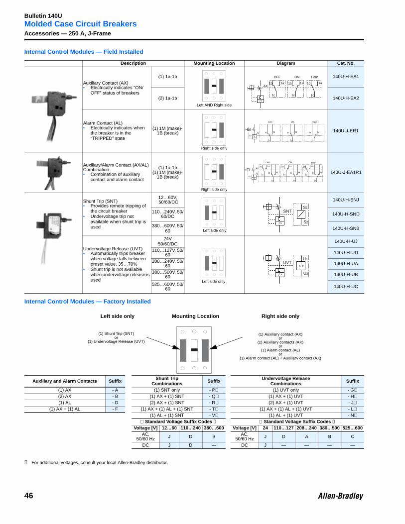
Molded Case Circuit BreakersAccessories — 250 A, J-FrameInternal Control Modules — Field Installed
Internal Control Modules — Factory Installed
➊ For additional voltages, consult your local Allen-Bradley distributor.
Description Mounting Location Diagram Cat. No.
Auxiliary Contact (AX)• Electrically indicates “ON/
OFF” status of breakers
(1) 1a-1b 140U-H-EA1
(2) 1a-1b 140U-H-EA2
Alarm Contact (AL)• Electrically indicates when
the breaker is in the “TRIPPED” state
(1) 1M (make)- 1B (break) 140U-J-ER1
Auxiliary/Alarm Contact (AX/AL) Combination• Combination of auxiliary
contact and alarm contact
(1) 1a-1b(1) 1M (make)-
1B (break)140U-J-EA1R1
Shunt Trip (SNT)• Provides remote tripping of
the circuit breaker• Undervoltage trip not
available when shunt trip is used
12…60V, 50/60/DC 140U-H-SNJ
110…240V, 50/60/DC 140U-H-SND
380…600V, 50/60 140U-H-SNB
Undervoltage Release (UVT)• Automatically trips breaker
when voltage falls between preset value, 35…70%
• Shunt trip is not available when undervoltage release is used
24V50/60/DC 140U-H-UJ
110…127V, 50/60 140U-H-UD
208…240V, 50/60 140U-H-UA
380…500V, 50/60 140U-H-UB
525…600V, 50/60 140U-H-UC
Auxiliary and Alarm Contacts Suffix Shunt TripCombinations Suffix Undervoltage Release
Combinations Suffix
(1) AX - A (1) SNT only - P⊗ (1) UVT only - G⊗(2) AX - B (1) AX + (1) SNT - Q⊗ (1) AX + (1) UVT - H⊗(1) AL - D (2) AX + (1) SNT - R⊗ (2) AX + (1) UVT - J⊗
(1) AX + (1) AL - F (1) AX + (1) AL + (1) SNT - T⊗ (1) AX + (1) AL + (1) UVT - L⊗(1) AL + (1) SNT - V⊗ (1) AL + (1) UVT - N⊗
⊗ Standard Voltage Suffix Codes ➊ ⊗ Standard Voltage Suffix Codes ➊Voltage [V] 12…60 110…240 380…600 Voltage [V] 24 110…127 208…240 380…500 525…600
AC, 50/60 Hz J D B AC,
50/60 Hz J D A B C
DC J D — DC J — — — —
Left AND Right side
1b
1c
1a
I >
AX
ON
1b
1c
1a
OFF
1b
1c
1a
TRIP
Right side only
I >
ON
B
1c
M
OFF TRIP
AL B
1c
M B
1c
M
Right side only
1b
1c
1a
I >
AX
ON
B
1c
M
OFF TRIP
AL
1b
1c
1a
B
1c
M
1b
1c
1a
B
1c
M
Left side only
S1
I >
SNT
S2
Left side only
U1
I >
UVT
U2
U >
(1) Shunt Trip (SNT)or
(1) Undervoltage Release (UVT)
(1) Auxiliary contact (AX)or
(2) Auxiliary contacts (AX)or
(1) Alarm contact (AL)or
(1) Alarm contact (AL) + Auxiliary contact (AX)
Mounting LocationLeft side only Right side only
46
Bulletin 140U
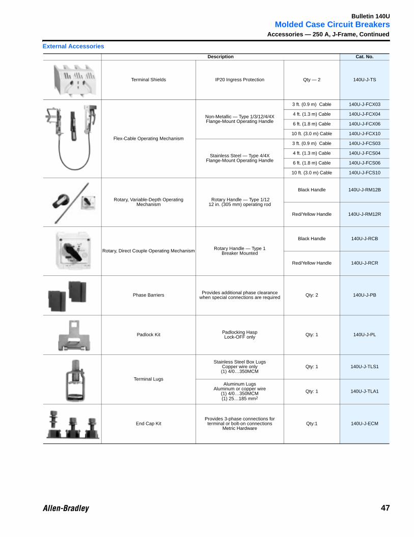
Molded Case Circuit BreakersAccessories — 250 A, J-Frame, Continued
External Accessories
Description Cat. No.
Terminal Shields IP20 Ingress Protection Qty — 2 140U-J-TS
Flex-Cable Operating Mechanism
Non-Metallic — Type 1/3/12/4/4X Flange-Mount Operating Handle
3 ft. (0.9 m) Cable 140U-J-FCX03
4 ft. (1.3 m) Cable 140U-J-FCX04
6 ft. (1.8 m) Cable 140U-J-FCX06
10 ft. (3.0 m) Cable 140U-J-FCX10
Stainless Steel — Type 4/4X Flange-Mount Operating Handle
3 ft. (0.9 m) Cable 140U-J-FCS03
4 ft. (1.3 m) Cable 140U-J-FCS04
6 ft. (1.8 m) Cable 140U-J-FCS06
10 ft. (3.0 m) Cable 140U-J-FCS10
Rotary, Variable-Depth Operating Mechanism
Rotary Handle — Type 1/1212 in. (305 mm) operating rod
Black Handle 140U-J-RM12B
Red/Yellow Handle 140U-J-RM12R
Rotary, Direct Couple Operating Mechanism Rotary Handle — Type 1 Breaker Mounted
Black Handle 140U-J-RCB
Red/Yellow Handle 140U-J-RCR
Phase Barriers Provides additional phase clearance when special connections are required Qty: 2 140U-J-PB
Padlock Kit Padlocking HaspLock-OFF only Qty: 1 140U-J-PL
Terminal Lugs
Stainless Steel Box LugsCopper wire only(1) 4/0…350MCM
Qty: 1 140U-J-TLS1
Aluminum LugsAluminum or copper wire
(1) 4/0…350MCM(1) 25…185 mm2
Qty: 1 140U-J-TLA1
End Cap KitProvides 3-phase connections for terminal or bolt-on connections
Metric HardwareQty:1 140U-J-ECM
47
Bulletin 140U
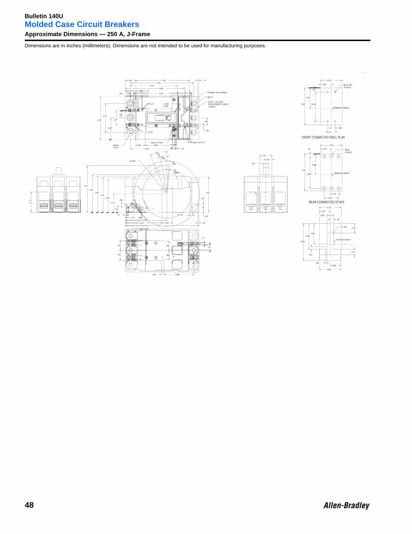
Molded Case Circuit BreakersApproximate Dimensions — 250 A, J-FrameDimensions are in inches (millimeters). Dimensions are not intended to be used for manufacturing purposes.
5.0486.000
4.4535.642
.281 5.500
.170
ØTYP(6)
.650
3.344
Ø.198
7.0001.000
.125
.624
.1883.194
3.3443.440
3.570
.260
.125
1.541
1.771
.949
.949 .859
.173
.625
.187
REF1.906
.500
4.427
˚
TRIP
4.0˚
˚
R2.656
4.000
2.000
1.062
2.062
3.9224.938
.625
1.875R.188
.281
.500
.688
1.375
5.500
2.062
3.922
4.125
7.000
2.062
4.125
7.000
.500 Ø6 HOLES
.625ØØ
1.375
2.750
6.000
2.062
4.125
2.750
Ø.145
3.978
.203
.664
.897 2.906
.594
1.188
.688
RTYP(4)
1.375
BREAKER HANDLEH
FRONT CONNECTED DRILL PLAN
REAR CONNECTED STUDS
BREAKER HANDLE
BREAKER HANDLEK
THERMAL ADJUSTMENT
.110 X .310 DEEP
4 HOLES
.256
GNETIC ADJUSTPUSH TO TRIP
#8-32 TAP4 HOLES
48
Bulletin 140U
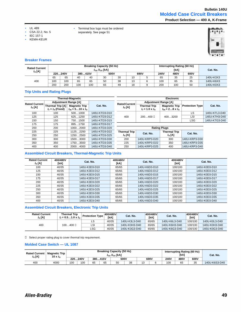
Molded Case Circuit BreakersProduct Selection — 400 A, K-Frame
Breaker Frames
Trip Units and Rating Plugs
Assembled Circuit Breakers, Thermal-Magnetic Trip Units
Assembled Circuit Breakers, Electronic Trip Units
➊ Select proper rating plug to cover thermal trip requirement.
Molded Case Switch — UL 1087
Rated Current In [A]
Breaking Capacity (50 Hz) Interrupting Rating (60 Hz) Cat. No.Icu /Ics [kA] [kA]
220…240V 380…415V 500V 690V 240V 480V 600V
40065 65 40 40 30 30 10 5 65 35 25 140U-K3X3100 100 65 65 50 38 13 6 100 65 35 140U-K6X3200 200 100 100 65 49 18 9 200 100 50 140U-K0X3
Thermal-Magnetic Electronic
Rated CurrentIn [A]
Adjustment Range [A]Cat. No.
Rated Current In [A]
Adjustment Range [A]Protection Type Cat. No.Thermal Trip [A]
Ir = In (Fixed)Magnetic Trip Im = 5…10 x In
Thermal Trip Ir = 1.0 x In
Magnetic Trip Im = 2…8 x In
100 100 500…1000 140U-KTD3-D10400 200…400 ➊ 400…3200
LS 140U-KTL3-D40125 125 625…1250 140U-KTD3-D12 LSI 140U-KTH3-D40150 150 750…1500 140U-KTD3-D15 LSG 140U-KTG3-D40175 175 895…1750 140U-KTD3-D17200 200 1000…2000 140U-KTD3-D20 Rating Plugs225 225 1125…2250 140U-KTD3-D22 Thermal Trip
In [A] Cat. No.Thermal Trip
In [A] Cat. No.250 250 1250…2500 140U-KTD3-D25300 300 1500…3000 140U-KTD3-D30 200 140U-KRP3-D20 300 140U-KRP3-D30350 350 1750…3500 140U-KTD3-D35 225 140U-KRP3-D22 350 140U-KRP3-D35400 400 2000…4000 140U-KTD3-D40 250 140U-KRP3-D25 400 140U-KRP3-D40
Rated CurrentIn [A]
400/480V [kA] Cat. No. 400/480V
[kA] Cat. No. 400/480V [kA] Cat. No.
100 40/35 140U-K3D3-D10 65/65 140U-K6D3-D10 100/100 140U-K0D3-D10125 40/35 140U-K3D3-D12 65/65 140U-K6D3-D12 100/100 140U-K0D3-D12150 40/35 140U-K3D3-D15 65/65 140U-K6D3-D15 100/100 140U-K0D3-D15175 40/35 140U-K3D3-D17 65/65 140U-K6D3-D17 100/100 140U-K0D3-D17200 40/35 140U-K3D3-D20 65/65 140U-K6D3-D20 100/100 140U-K0D3-D20225 40/35 140U-K3D3-D22 65/65 140U-K6D3-D22 100/100 140U-K0D3-D22250 40/35 140U-K3D3-D25 65/65 140U-K6D3-D25 100/100 140U-K0D3-D25300 40/35 140U-K3D3-D30 65/65 140U-K6D3-D30 100/100 140U-K0D3-D30350 40/35 140U-K3D3-D35 65/65 140U-K6D3-D35 100/100 140U-K0D3-D35400 40/35 140U-K3D3-D40 65/65 140U-K6D3-D40 100/100 140U-K0D3-D40
Rated CurrentIn [A]
Thermal Trip Ir = 0.5…1.0 x In
Protection Type 400/480V [kA] Cat. No. 400/480V
[kA] Cat. No. 400/480V [kA] Cat. No.
400 100…400 ➊LS 40/35 140U-K3L3-D40 65/65 140U-K6L3-D40 100/100 140U-K0L3-D40LSI 40/35 140U-K3H3-D40 65/65 140U-K6H3-D40 100/100 140U-K0H3-D40LSG 40/35 140U-K3G3-D40 65/65 140U-K6G3-D40 100/100 140U-K0G3-D40
Rated Current In [A]
Magnetic Trip 10 x In
Breaking Capacity (50 Hz) Interrupting Rating (60 Hz) [kA] Cat. No.Icu /Ics [kA]
220…240V 380…415V 500V 690V 240V 480V 600V400 4000 100 100 65 65 50 38 13 6 100 65 35 140U-K6S3-D40
• UL 489• CSA 22.2, No. 5• IEC 157-1• KEMA-KEUR
• Terminal box lugs must be ordered separately. See page 51
49
Bulletin 140U
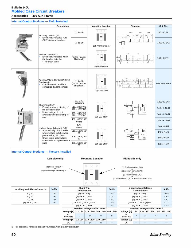
Molded Case Circuit BreakersAccessories — 400 A, K-FrameInternal Control Modules — Field Installed
Internal Control Modules — Factory Installed
➊ For additional voltages, consult your local Allen-Bradley distributor.
Description Mounting Location Diagram Cat. No.
Auxiliary Contact (AX)• Electrically indicates “ON/
OFF” status of breakers
(1) 1a-1b 140U-K-EA1
(2) 1a-1b 140U-K-EA2
Alarm Contact (AL)• Electrically indicates when
the breaker is in the “TRIPPED” state
(1) 1M (make)- 1B (break) 140U-K-ER1
\
Auxiliary/Alarm Contact (AX/AL) Combination• Combination of auxiliary
contact and alarm contact
(1) 1a-1b(1) 1M (make)-
1B (break)140U-K-EA1R1
Shunt Trip (SNT)• Provides remote tripping of
the circuit breaker• Undervoltage trip not
available when shunt trip is used
12…24V, 50/60/DC 140U-K-SNJ
110…240V AC, 110…125V DC 140U-K-SND
380…440V AC, 220…250V DC 140U-K-SNN
480…600V, 50/60 Hz 140U-K-SNB
Undervoltage Release (UVT)• Automatically trips breaker
when voltage falls between preset value, 35…70%
• Shunt trip is not available when undervoltage release is used
24V,50/60 140U-K-UJ
110…127V, 50/60 140U-K-UD
208…240V, 50/60 140U-K-UA
380…500V, 50/60 140U-K-UB
Auxiliary and Alarm Contacts Suffix Shunt TripCombinations Suffix Undervoltage Release
Combinations Suffix
(1) AX - A (1) SNT only - P⊗ (1) UVT only - G⊗(2) AX - B (1) AX + (1) SNT - Q⊗ (1) AX + (1) UVT - H⊗(1) AL - D (2) AX + (1) SNT - R⊗ (2) AX + (1) UVT - J⊗
(1) AX + (1) AL - F (1) AX + (1) AL + (1) SNT - T⊗ (1) AX + (1) AL + (1) UVT - L⊗(1) AL + (1) SNT - V⊗ (1) AL + (1) UVT - N⊗
⊗ Standard Voltage Suffix Codes ➊ ⊗ Standard Voltage Suffix Codes ➊Voltage [V] 12…24 110…240 380…440 480…600 Voltage [V] 24 110…127 208…240 380…480
AC50/60 Hz J D N B AC
50/60 Hz J D A B
Voltage [V] 12…24 110…125 220…250 — Voltage [V] — — — —DC J D N — DC — — — —
Left AND Right side
1b
1c
1a
I >
AX
ON
1b
1c
1a
OFF
1b
1c
1a
TRIP
Right side ONLY
I >
ON
B
1c
M
OFF TRIP
AL B
1c
M B
1c
M
Right side ONLY
1b
1c
1a
I >
AX
ON
B
1c
M
OFF TRIP
AL
1b
1c
1a
B
1c
M
1b
1c
1a
B
1c
M
Left side ONLY
S1
I >
SNT
S2
Left side ONLY
U1
I >
UVT
U2
U >
(1) Shunt Trip (SNT)or
(1) Undervoltage Release (UVT)
(1) Auxiliary contact (AX)or
(2) Auxiliary contacts (AX)or
(1) Alarm contact (AL)or
(1) Alarm contact (AL) + Auxiliary contact (AX)
Mounting LocationLeft side only Right side only
50
Bulletin 140U
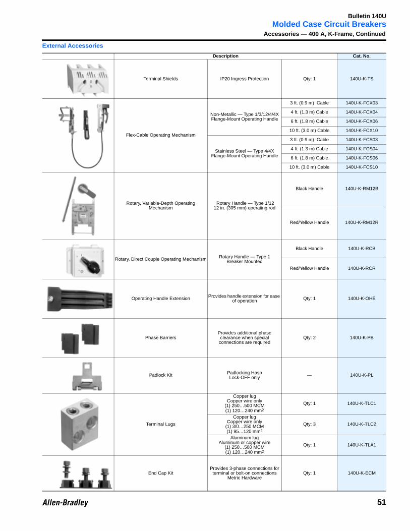
Molded Case Circuit BreakersAccessories — 400 A, K-Frame, Continued
External Accessories
Description Cat. No.
Terminal Shields IP20 Ingress Protection Qty: 1 140U-K-TS
Flex-Cable Operating Mechanism
Non-Metallic — Type 1/3/12/4/4X Flange-Mount Operating Handle
3 ft. (0.9 m) Cable 140U-K-FCX03
4 ft. (1.3 m) Cable 140U-K-FCX04
6 ft. (1.8 m) Cable 140U-K-FCX06
10 ft. (3.0 m) Cable 140U-K-FCX10
Stainless Steel — Type 4/4X Flange-Mount Operating Handle
3 ft. (0.9 m) Cable 140U-K-FCS03
4 ft. (1.3 m) Cable 140U-K-FCS04
6 ft. (1.8 m) Cable 140U-K-FCS06
10 ft. (3.0 m) Cable 140U-K-FCS10
Rotary, Variable-Depth Operating Mechanism
Rotary Handle — Type 1/1212 in. (305 mm) operating rod
Black Handle 140U-K-RM12B
Red/Yellow Handle 140U-K-RM12R
Rotary, Direct Couple Operating Mechanism Rotary Handle — Type 1 Breaker Mounted
Black Handle 140U-K-RCB
Red/Yellow Handle 140U-K-RCR
Operating Handle Extension Provides handle extension for ease of operation Qty: 1 140U-K-OHE
Phase BarriersProvides additional phase clearance when special
connections are requiredQty: 2 140U-K-PB
Padlock Kit Padlocking HaspLock-OFF only — 140U-K-PL
Terminal Lugs
Copper lugCopper wire only
(1) 250…500 MCM(1) 120…240 mm2
Qty: 1 140U-K-TLC1
Copper lugCopper wire only
(1) 3/0…250 MCM(1) 95…120 mm2
Qty: 3 140U-K-TLC2
Aluminum lugAluminum or copper wire
(1) 250…500 MCM(1) 120…240 mm2
Qty: 1 140U-K-TLA1
End Cap KitProvides 3-phase connections for terminal or bolt-on connections
Metric HardwareQty: 1 140U-K-ECM
51
Bulletin 140U
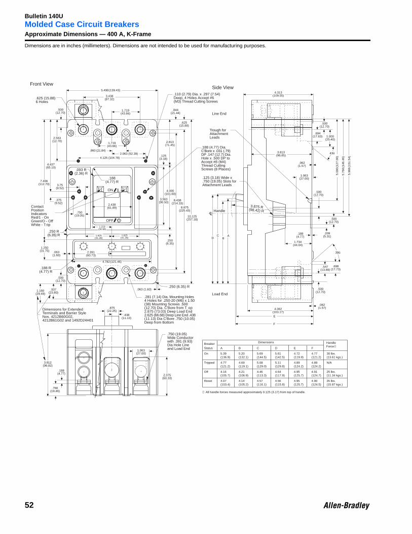
Molded Case Circuit BreakersApproximate Dimensions — 400 A, K-FrameDimensions are in inches (millimeters). Dimensions are not intended to be used for manufacturing purposes.
.875(22.25)
.438(11.13)
.500(12.70)
2.391(60.73)
5.490(139.43)
.188(4.77)
10.125(257.18)
8.438(214.33)
8.875(225.43)
3.563(90.50)
4.000(101.60)
2.813(71.45)
.125(3.18)
1.719(43.66)
3.438(87.32)
.625(15.88)
1.063(27.00)
.766(19.46)
2.375(60.33)
.250(6.35)
.188 R(4.77) R
.063(1.60)
1.250(31.75)
.698(17.73)
.250 R(6.35) R
Dimensions for ExtendedTerminals and Barrier StyleNos. 4212B60G02,4212B61G02 and 1492D24H01
3.812(96.82)
1.160(29.49)
.937(23.80)
.281 (7.14) Dia. Mounting Holes4 Holes for .250-20 (M6) x 1.50(38) Mounting Screws .500(12.70) Dia. C'Bore from T op2.875 (73.03) Deep Load End2.625 (66.68) Deep Line End .438(11.13) Dia C'Bore .750 (10.05)Deep from Bottom
.750 (19.05)Wide Conductorwith .391 (9.93)Dia Hole Lineand Load End
1.625(41.28)
1.625(41.28)
1.219(30.96)
7.406(112.70)
4.437(65.10)
2.563(12.70)
.375(9.52)
ContactPositionIndicatorsRed/1 - OnGreen/O - OffWhite - T rip
.500(12.70)
4.125 (104.78)
1.719(43.66)
.860 (21.84)2.063 (52.39)
.750(19.05)
.188(4.77) R
.093 R(2.36) R
ON
OFF
F
E
.500(12.70)
.062(1.57)4.062
(103.17)
39û
.547(13.89)
1.734(44.04)
.209(5.31)
.188(4.77)
.500(12.70)
.500(12.70)
.062(1.57)
1.063(27.00)
3.813(96.85)
1.000(25.40)
5.00
0(1
27.0
0)
5.96
6(1
51.5
4)
5.76
6(1
46.4
6)
43û
.694(17.63)
.500(12.70)
4.313(109.55)
D
.188 (4.77) Dia.C'Bore x .031 (.79)DP .147 (12.7) Dia.Hole x .500 DP toAccept #8 (M4)Thread CuttingScrews (8 Places)
.125 (3.18) Wide x
.750 (19.05) Slots forAttachment Leads
CB
A
Trough forAttachmentLeads
.625 (15.88)6 Holes
3.75(9.52)
.844(21.44)
.110 (2.79) Dia. x .297 (7.54)Deep, 4 Holes Accept #6(M3) Thread Cutting Screws
.250 (6.35) R.063 (1.60)
3.875 R(98.42) RHandle
CL
4.782(121.46)
2.438(61.89)
Front ViewSide View
Line End
Load End
Breaker Dimensions
Status A B C D E F
On 5.39 5.20 5.69 5.61 4.72 4.77 30 lbs.(136.9) (132.1) (144.5) (142.5) (119.9) (121.2) (13.61 kgs.)
Tripped 4.77 4.69 5.08 5.11 4.89 4.89 N/A(121.2) (119.1) (129.0) (129.8) (124.2) (124.2)
Off 4.16 4.21 4.46 4.64 4.95 4.91 25 lbs.(105.7) (106.9) (113.3) (117.9) (125.7) (124.7) (11.34 kgs.)
Reset 4.07 4.14 4.57 4.56 4.95 4.90 35 lbs.(103.4) (105.2) (116.1) (115.8) (125.7) (124.5) (15.87 kgs.)
➀ All handle forces measured approximately 0.125 (3.17) from top of handle.
HandleForce➀
52
Bulletin 140U
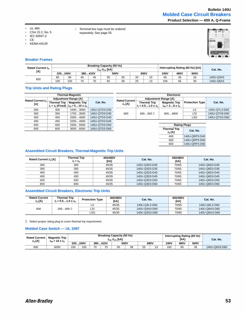
Molded Case Circuit BreakersProduct Selection — 600 A, Q-Frame
Breaker Frames
Trip Units and Rating Plugs
Assembled Circuit Breakers, Thermal-Magnetic Trip Units
Assembled Circuit Breakers, Electronic Trip Units
➊ Select proper rating plug to cover thermal trip requirement.
Molded Case Switch — UL 1087
Rated Current In [A]
Breaking Capacity (50 Hz)Interrupting Rating (60 Hz) [kA]
Cat. No.Icu /Ics [kA]220…240V 380…415V 500V 690V 240V 480V 600V
60085 85 45 45 30 30 20 10 65 35 25 140U-Q3X3100 100 70 70 50 38 25 13 100 65 35 140U-Q6X3
Thermal-Magnetic Electronic
Rated Current In [A]
Adjustment Range [A]Cat. No.
Rated Current In [A]
Adjustment Range [A]Protection Type Cat. No.Thermal Trip
Ir = In (Fixed)Magnetic Trip Im = 5…10 x In
Thermal TripIr = 0.5…1.0 x In
Magnetic Trip Im = 2…8 x In
300 300 1500…3000 140U-QTD3-D30600 400…600 ➊ 800…4800
LS 140U-QTL3-D60350 350 1750…3500 140U-QTD3-D35 LSI 140U-QTH3-D60400 400 2000…4000 140U-QTD3-D40 LSG 140U-QTG3-D60450 450 2250…4500 140U-QTD3-D45500 500 2500…5000 140U-QTD3-D50 Rating Plugs600 600 3000…6000 140U-QTD3-D60 Thermal Trip
In [A] Cat. No.
400 140U-QRP3-D40500 140U-QRP3-D50600 140U-QRP3-D60
Rated Current In [A] Thermal TripIr = In
400/480V[kA] Cat. No. 400/480V
[kA] Cat. No.
300 300 45/35 140U-Q3D3-D30 70/65 140U-Q6D3-D30350 350 45/35 140U-Q3D3-D35 70/65 140U-Q6D3-D35400 400 45/35 140U-Q3D3-D40 70/65 140U-Q6D3-D40450 450 45/35 140U-Q3D3-D45 70/65 140U-Q6D3-D45500 500 45/35 140U-Q3D3-D50 70/65 140U-Q6D3-D50600 600 45/35 140U-Q3D3-D60 70/65 140U-Q6D3-D60
Rated Current In [A]
Thermal TripIr = 0.5…1.0 x In
Protection Type 400/480V[kA] Cat. No. 400/480V
[kA] Cat. No.
600 200…600 ➊LS 45/35 140U-Q3L3-D60 70/65 140U-Q6L3-D60LSI 45/35 140U-Q3H3-D60 70/65 140U-Q6H3-D60LSG 45/35 140U-Q3G3-D60 70/65 140U-Q6G3-D60
Rated CurrentIn [A]
Magnetic TripIm = 10 x In
Breaking Capacity (50 Hz) Interrupting Rating (60 Hz) [kA] Cat. No.Icu /Ics [kA]
220…240V 380…415V 500V 690V 240V 480V 600V600 6000 100 100 70 70 50 38 25 13 100 65 35 140U-Q6S3-D60
• UL 489• CSA 22.2, No. 5• IEC 60947-2• CE• KEMA-KEUR
• Terminal box lugs must be ordered separately. See page 55
53
Bulletin 140U
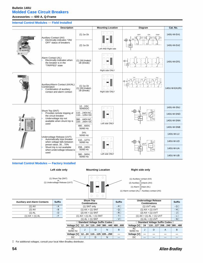
Molded Case Circuit BreakersAccessories — 600 A, Q-FrameInternal Control Modules — Field Installed
Internal Control Modules — Factory Installed
➊ For additional voltages, consult your local Allen-Bradley distributor.
Description Mounting Location Diagram Cat. No.
Auxiliary Contact (AX)• Electrically indicates “ON/
OFF” status of breakers
(1) 1a-1b 140U-M-EA1
(2) 1a-1b 140U-M-EA2
Alarm Contact (AL)• Electrically indicates when
the breaker is in the “TRIPPED” state
(1) 1M (make)- 1B (break) 140U-M-ER1
\
Auxiliary/Alarm Contact (AX/AL) Combination• Combination of auxiliary
contact and alarm contact
(1) 1a-1b(1) 1M (make)-
1B (break)140U-M-EA1R1
Shunt Trip (SNT)• Provides remote tripping of
the circuit breaker• Undervoltage trip not
available when shunt trip is used
12…24V, 50/60/DC 140U-M-SNJ
110…240V AC, 110…125V DC 140U-M-SND
380…440V AC, 220…250V DC 140U-M-SNN
480…600V, 50/60 Hz 140U-M-SNB
Undervoltage Release (UVT)• Automatically trips breaker
when voltage falls between preset value, 35…70%
• Shunt trip is not available when undervoltage release is used
24V,50/60 Hz 140U-M-UJ
110…127V, 50/60 Hz 140U-M-UD
208…240V, 50/60 Hz 140U-M-UA
380…500V, 50/60 Hz 140U-M-UB
Auxiliary and Alarm Contacts Suffix Shunt TripCombinations Suffix Undervoltage Release
Combinations Suffix
(1) AX - A (1) SNT only - P⊗ (1) UVT only - G⊗(2) AX - B (1) AX + (1) SNT - Q⊗ (1) AX + (1) UVT - H⊗(1) AL - D (2) AX + (1) SNT - R⊗ (2) AX + (1) UVT - J⊗
(1) AX + (1) AL - F (1) AX + (1) AL + (1) SNT - T⊗ (1) AX + (1) AL + (1) UVT - L⊗(1) AL + (1) SNT - V⊗ (1) AL + (1) UVT - N⊗
⊗ Standard Voltage Suffix Codes ➊ ⊗ Standard Voltage Suffix Codes ➊Voltage [V] 12…24 110…240 380…440 480…600 Voltage [V] 24 110…127 208…240 380…480
AC50/60 Hz J D N B AC
50/60 Hz J D A B
Voltage [V] 12…24 110…125 220…250 — Voltage [V] — — — —DC J D N — DC — — — —
Left AND Right side
1b
1c
1a
I >
AX
ON
1b
1c
1a
OFF
1b
1c
1a
TRIP
Right side ONLY
I >
ON
B
1c
M
OFF TRIP
AL B
1c
M B
1c
M
Right side ONLY
1b
1c
1a
I >
AX
ON
B
1c
M
OFF TRIP
AL
1b
1c
1a
B
1c
M
1b
1c
1a
B
1c
M
Left side ONLY
S1
I >
SNT
S2
Left side ONLY
U1
I >
UVT
U2
U >
(1) Shunt Trip (SNT)or
(1) Undervoltage Release (UVT)
(1) Auxiliary contact (AX)or
(2) Auxiliary contacts (AX)or
(1) Alarm contact (AL)or
(1) Alarm contact (AL) + Auxiliary contact (AX)
Mounting LocationLeft side only Right side only
54
Bulletin 140U
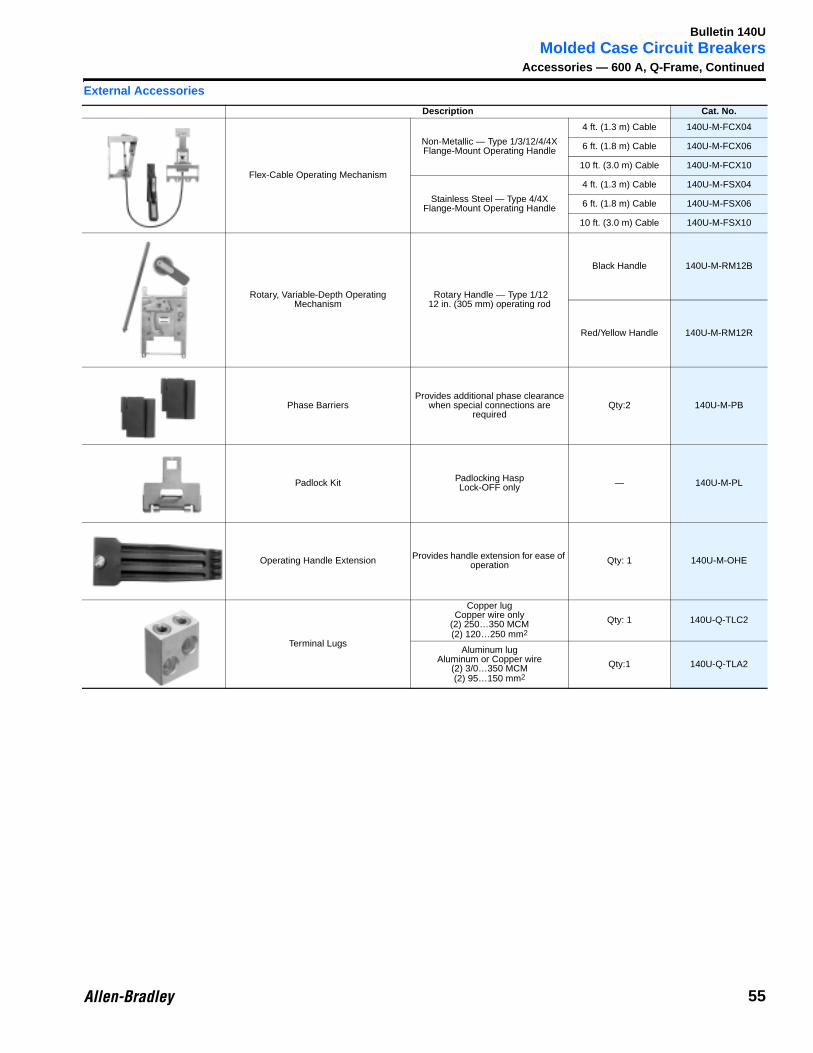
Molded Case Circuit BreakersAccessories — 600 A, Q-Frame, Continued
External Accessories
Description Cat. No.
Flex-Cable Operating Mechanism
Non-Metallic — Type 1/3/12/4/4X Flange-Mount Operating Handle
4 ft. (1.3 m) Cable 140U-M-FCX04
6 ft. (1.8 m) Cable 140U-M-FCX06
10 ft. (3.0 m) Cable 140U-M-FCX10
Stainless Steel — Type 4/4X Flange-Mount Operating Handle
4 ft. (1.3 m) Cable 140U-M-FSX04
6 ft. (1.8 m) Cable 140U-M-FSX06
10 ft. (3.0 m) Cable 140U-M-FSX10
Rotary, Variable-Depth Operating Mechanism
Rotary Handle — Type 1/1212 in. (305 mm) operating rod
Black Handle 140U-M-RM12B
Red/Yellow Handle 140U-M-RM12R
Phase BarriersProvides additional phase clearance
when special connections are required
Qty:2 140U-M-PB
Padlock Kit Padlocking HaspLock-OFF only — 140U-M-PL
Operating Handle Extension Provides handle extension for ease of operation Qty: 1 140U-M-OHE
Terminal Lugs
Copper lugCopper wire only
(2) 250…350 MCM(2) 120…250 mm2
Qty: 1 140U-Q-TLC2
Aluminum lugAluminum or Copper wire
(2) 3/0…350 MCM(2) 95…150 mm2
Qty:1 140U-Q-TLA2
55
Bulletin 140U
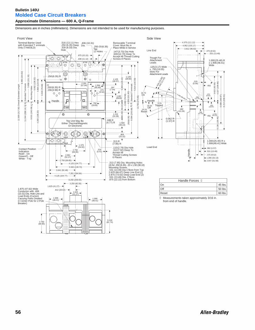
Molded Case Circuit BreakersApproximate Dimensions — 600 A, Q-FrameDimensions are in inches (millimeters). Dimensions are not intended to be used for manufacturing purposes.
.516 (13.11) Hex
.250 (6.35) Deep
.328 (8.33) Dia.Hole
9.53
1 (2
42.0
9)
/
M
ount
ing
Hol
es
6.48
9 (1
64.8
2)
5.95
8 (1
51.3
3)
5.05
2 (1
28.3
2)
4.86
4 (1
23.5
4)
12.5
00 (
317.
50)
Ove
rall
Ext
ende
d Le
ngth
Terminal Barrier Usedwith Extended T erminalsOnly (TA603LD)
Removable T erminalCover Must Be inPlace While in Service
.250(6.35) R
.250(6.35) R
.156(3.96) R
.188 R(4.77) R
Han
dle
C L
HandleCLHandleCL
1.625(41.27)
11.3
44 (
288.
14)
/
E
xten
ded
Ter
min
als
3.01
9 (7
6.68
)
.297(7.54)
1.125(28.57)
1.232(31.29)
.438 (11.12)
.875 (22.22)
.406 (10.31)Dia. .250-20(6.35)
Tap12 Holes .147(3.73) Dia Hole
.500(12.70) Deep ToAccept #8 Thread CuttingScrews 8 Places
1.142(29.00)
3.09
4 (7
8.59
)
4.00
0 (1
01.6
0).2
50(6
.35)
5.08
3 (1
29.1
0)
1.126(28.60)
9.59
4 (2
43.6
8)
/
Sta
ndar
d T
erm
inal
s
5.61
4 (1
42.5
9)
10.7
50 (2
73.0
5)
Trough ForAttachmentLeads
.125(3.17) Widex .750 (19.05)Slots ForAttachment Leads
14.7ûOn
24.2ûReset
19.2ûOff
0.2ûTripped
.616
(15.
65)
.442
(11.
23)
2.29
2 (5
8.22
)
2.750(69.85)
1.375(34.92)
7.281 (184.94)
3.641 (92.48)
5.500 (139.70)
4.125 (104.77)
2.750 (69.85)
2.062(52.37)
8.250 (209.55)
Contact PositionIndicatorsRed/I - OnGreen/O - OffWhite - T rip
4.125 (104.77)
.313 (7.95) Dia. Mounting Holes(4) for .250 (6.35) - 20 x 1.50 (38.10)Mounting Screws.531 (13.49) Dia C'Bore from Top2.625 (66.67) Deep Line End (2)2.875 (73.02) Deep Load End (2).531 (13.49) Dia. C'Bore.875 (22.22) from Bottom
1.625 (41.27)
.812 (20.62)
1.906(48.41)
1.906(48.41)
3.250 (82.55)
1.875 (47.62) WideConductor with .406(10.31) Dia. Hole Line andLoad Ends (CurrentCarrying Parts Omittedin Center Pole for 2-PoleBreaker)
1.500(38.10)
.313 R(7.95) R
.110(2.79) Dia Hole
.312(7.92) Deep ToAccept #6Thread Cutting Screws6 Places
.016(0.41)
.800(20.32)
B
3.218(81.74)2.750
(69.85)
1.000(25.40) R x1.906(48.41) Wide
.062 (1.57)
.531 (13.49)
.375 (9.52)
1.265 (32.13)
2.047 (51.99)
.219(5.56)
6.68
8 (1
69.8
7)
8.21
3 (2
08.6
1)
45û
.500(12.70)
.482(12.24)
45û
.500(12.70)
.375(9.52)
.420(10.67)
.1.151(29.23)
4.32
7 (1
09.9
0)5.
136
(130
.45)
3.62
2 (9
2.00
)
0.062 R(1.57) R
3.496 (88.80) R
A
4.062 (103.17)
4.375 (111.12)
3.812 (96.82)
.531 (13.49).375 (9.52)
1.000(25.40) Rx 1.906 (48.41)Wide
On/I On/I
Off/O Off/O
C LC L
C LC L
C LC L
Trip Unit May BeEither Thermal/Magnetic
Or Electronic
4.26
0 (1
08.2
0)
2.281(57.94) 1.594
(40.49).375
(9.52)
.750(19.05)
Front View Side View
Line End
Load End
Handle Forces ➀
On 45 lbs.
Off 50 lbs.
Reset 60 lbs.
➀ Measurements taken approximately 3/16 in.from end of handle.
56
Bulletin 140U
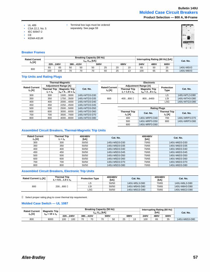
Molded Case Circuit BreakersProduct Selection — 800 A, M-Frame
Breaker Frames
Trip Units and Rating Plugs
Assembled Circuit Breakers, Thermal-Magnetic Trip Units
Assembled Circuit Breakers, Electronic Trip Units
➊ Select proper rating plug to cover thermal trip requirement.
Molded Case Switch — UL 1087
Rated CurrentIn [A]
Breaking Capacity (50 Hz)Interrupting Rating (60 Hz) [kA]
Cat. No.Icu /Ics [kA]220…240V 380…415V 500V 690V 240V 480V 600V
80065 65 50 50 50 25 20 10 65 50 25 140U-M5X3100 100 70 70 70 50 25 13 100 65 35 140U-M6X3
Thermal-Magnetic Electronic
Rated CurrentIn [A]
Adjustment Range [A]Cat. No.
Rated Current In [A]
Adjustment Range [A]Protection
Type Cat. No.Thermal TripIr = In
Magnetic Trip Im = 5…10 x In
Thermal TripIr = 1.0 x In
Magnetic Trip Im = 2…8 x In
300 300 1500…3000 140U-MTD3-D30800 400…800 ➊ 800…6400
LS 140U-MTL3-D80350 350 1750…3500 140U-MTD3-D35 LSI 140U-MTH3-D80400 400 2000…4000 140U-MTD3-D40 LSG 140U-MTG3-D80450 450 2250…4500 140U-MTD3-D45500 500 2500…5000 140U-MTD3-D50 Rating Plugs600 600 3000…6000 140U-MTD3-D60 Thermal Trip
In [A] Cat. No.Thermal Trip
In [A] Cat. No.700 700 3500…7000 140U-MTD3-D70800 800 4000…8000 140U-MTD3-D80 400 140U-MRP3-D40 700 140U-MRP3-D70
500 140U-MRP3-D50 800 140U-MRP3-D80600 140U-MRP3-D60
Rated Current In [A]
Thermal TripIr = In
400/480V[kA] Cat. No. 400/480V
[kA] Cat. No.
300 300 50/50 140U-M5D3-D30 70/65 140U-M6D3-D30350 350 50/50 140U-M5D3-D35 70/65 140U-M6D3-D35400 400 50/50 140U-M5D3-D40 70/65 140U-M6D3-D40450 450 50/50 140U-M5D3-D45 70/65 140U-M6D3-D45500 500 50/50 140U-M5D3-D50 70/65 140U-M6D3-D50600 600 50/50 140U-M5D3-D60 70/65 140U-M6D3-D60700 700 50/50 140U-M5D3-D70 70/65 140U-M6D3-D70800 800 50/50 140U-M5D3-D80 70/65 140U-M6D3-D80
Rated Current In [A] Thermal TripIr = 0.5…1.0 x In
Protection Type 400/480V[kA] Cat. No. 400/480V
[kA] Cat. No.
800 200…800 ➊LS 50/50 140U-M5L3-D80 70/65 140U-M6L3-D80LSI 50/50 140U-M5H3-D80 70/65 140U-M6H3-D80LSG 50/50 140U-M5G3-D80 70/65 140U-M6G3-D80
Rated CurrentIn [A]
Magnetic TripIm = 10 x In
Breaking Capacity (50 Hz) Interrupting Rating (60 Hz) [kA] Cat. No.Icu /Ics [kA]
220…240V 380…415V 500V 690V 240V 480V 600V800 8000 100 100 70 70 70 50 25 13 100 65 35 140U-M6S3-D80
• UL 489• CSA 22.2, No. 5• IEC 60947-2• CE• KEMA-KEUR
• Terminal box lugs must be ordered separately. See page 59
57

Bulletin 140U
Molded Case Circuit BreakersAccessories — 800 A, M-FrameInternal Control Modules — Field Installed
Internal Control Modules — Factory Installed
➊ For additional voltages, consult your local Allen-Bradley distributor.
Description Mounting Location Diagram Cat. No.
Auxiliary Contact (AX)• Electrically indicates “ON/
OFF” status of breakers
(1) 1a-1b 140U-M-EA1
(2) 1a-1b 140U-M-EA2
Alarm Contact (AL)• Electrically indicates when
the breaker is in the “TRIPPED” state
(1) 1M (make)- 1B (break) 140U-M-ER1
\
Auxiliary/Alarm Contact (AX/AL) Combination• Combination of auxiliary
contact and alarm contact
(1) 1a-1b(1) 1M (make)-
1B (break)140U-M-EA1R1
Shunt Trip (SNT)• Provides remote tripping of
the circuit breaker• Undervoltage trip not
available when shunt trip is used
12…24V, 50/60/DC 140U-M-SNJ
110…240V AC, 110…125V DC 140U-M-SND
380…440V AC, 220…250V DC 140U-M-SNN
480…600V, 50/60 Hz 140U-M-SNB
Undervoltage Release (UVT)• Automatically trips breaker
when voltage falls between preset value, 35…70%
• Shunt trip is not available when undervoltage release is used
24V AC,50/60 Hz 140U-M-UJ
110…127V AC,50/60 Hz 140U-M-UD
208…240V AC,50/60 Hz 140U-M-UA
380…500V AC, 50/60 Hz 140U-M-UB
Auxiliary and Alarm Contacts Suffix Shunt TripCombinations Suffix Undervoltage Release
Combinations Suffix
(1) AX - A (1) SNT only - P⊗ (1) UVT only - G⊗(2) AX - B (1) AX + (1) SNT - Q⊗ (1) AX + (1) UVT - H⊗(1) AL - D (2) AX + (1) SNT - R⊗ (2) AX + (1) UVT - J⊗
(1) AX + (1) AL - F (1) AX + (1) AL + (1) SNT - T⊗ (1) AX + (1) AL + (1) UVT - L⊗(1) AL + (1) SNT - V⊗ (1) AL + (1) UVT - N⊗
⊗ Standard Voltage Suffix Codes ➊ ⊗ Standard Voltage Suffix Codes ➊Voltage [V] 12…24 110…240 380…440 480…600 Voltage [V] 24 110…127 208…240 380…480
AC,50/60 Hz J D N B AC,
50/60 Hz J D A B
Voltage [V] 12…24 110…125 220…250 — Voltage [V] — — — —DC J D N — DC — — — —
Left AND Right side
1b
1c
1a
I >
AX
ON
1b
1c
1a
OFF
1b
1c
1a
TRIP
Right side ONLY
I >
ON
B
1c
M
OFF TRIP
AL B
1c
M B
1c
M
Right side ONLY
1b
1c
1a
I >
AX
ON
B
1c
M
OFF TRIP
AL
1b
1c
1a
B
1c
M
1b
1c
1a
B
1c
M
Left side ONLY
S1
I >
SNT
S2
Left side ONLY
U1
I >
UVT
U2
U >
(1) Shunt Trip (SNT)or
(1) Undervoltage Release (UVT)
(1) Auxiliary contact (AX)or
(2) Auxiliary contacts (AX)or
(1) Alarm contact (AL)or
(1) Alarm contact (AL) + Auxiliary contact (AX)
Mounting LocationLeft side only Right side only
58
Bulletin 140U
Molded Case Circuit BreakersAccessories — 800 A, M-Frame, Continued
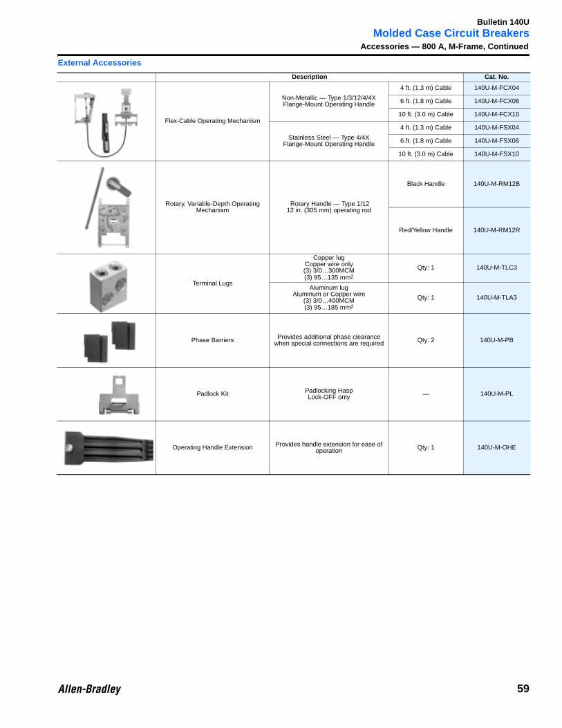
External Accessories
Description Cat. No.
Flex-Cable Operating Mechanism
Non-Metallic — Type 1/3/12/4/4X Flange-Mount Operating Handle
4 ft. (1.3 m) Cable 140U-M-FCX04
6 ft. (1.8 m) Cable 140U-M-FCX06
10 ft. (3.0 m) Cable 140U-M-FCX10
Stainless Steel — Type 4/4X Flange-Mount Operating Handle
4 ft. (1.3 m) Cable 140U-M-FSX04
6 ft. (1.8 m) Cable 140U-M-FSX06
10 ft. (3.0 m) Cable 140U-M-FSX10
Rotary, Variable-Depth Operating Mechanism
Rotary Handle — Type 1/1212 in. (305 mm) operating rod
Black Handle 140U-M-RM12B
Red/Yellow Handle 140U-M-RM12R
Terminal Lugs
Copper lugCopper wire only(3) 3/0…300MCM(3) 95…135 mm2
Qty: 1 140U-M-TLC3
Aluminum lugAluminum or Copper wire
(3) 3/0…400MCM(3) 95…185 mm2
Qty: 1 140U-M-TLA3
Phase Barriers Provides additional phase clearance when special connections are required Qty: 2 140U-M-PB
Padlock Kit Padlocking HaspLock-OFF only — 140U-M-PL
Operating Handle Extension Provides handle extension for ease of operation Qty: 1 140U-M-OHE
59
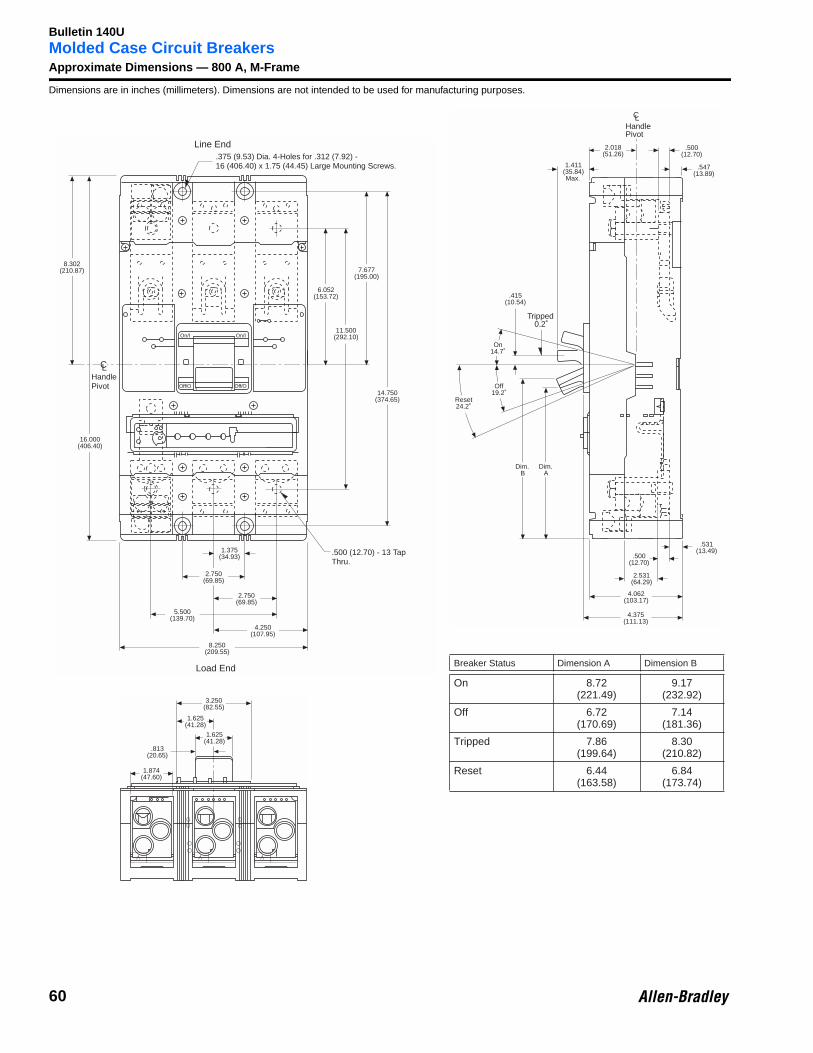
Bulletin 140U
Molded Case Circuit BreakersApproximate Dimensions — 800 A, M-FrameDimensions are in inches (millimeters). Dimensions are not intended to be used for manufacturing purposes.
HandlePivot
1.375(34.93)
2.750(69.85)
2.750(69.85)
5.500(139.70)
4.250(107.95)
8.250(209.55)
.375 (9.53) Dia. 4-Holes for .312 (7.92) -16 (406.40) x 1.75 (44.45) Large Mounting Screws.
16.000(406.40)
8.302(210.87)
6.052(153.72)
14.750(374.65)
7.677(195.00)
11.500(292.10)
.500 (12.70) - 13 TapThru.
Line End
Load End
CL
On/I On/I
Off/O Off/O
1.874(47.60)
3.250(82.55)
1.625(41.28)
1.625(41.28)
.813(20.65)
.547(13.89)
.531(13.49)
.500(12.70)
2.531(64.29)
4.062(103.17)
4.375(111.13)
On14.7˚
Off19.2˚
Reset24.2˚
Tripped0.2˚
.500(12.70)
1.411(35.84)Max.
HandlePivot
LC
.415(10.54)
Dim.B
Dim.A
2.018(51.26)
Breaker Status Dimension A Dimension B
On 8.72(221.49)
9.17(232.92)
Off 6.72(170.69)
7.14(181.36)
Tripped 7.86(199.64)
8.30(210.82)
Reset 6.44(163.58)
6.84(173.74)
60
Bulletin 140U
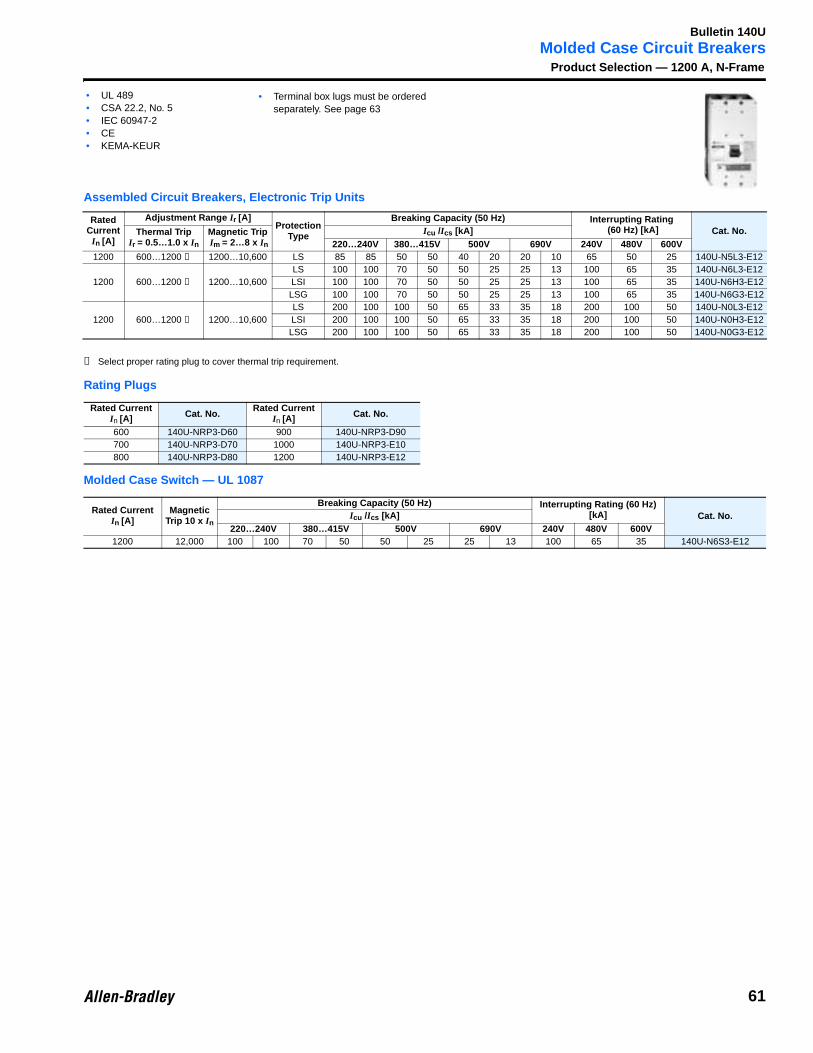
Molded Case Circuit BreakersProduct Selection — 1200 A, N-Frame
Assembled Circuit Breakers, Electronic Trip Units
➊ Select proper rating plug to cover thermal trip requirement.
Rating Plugs
Molded Case Switch — UL 1087
Rated Current
In [A]
Adjustment Range Ir [A]Protection
Type
Breaking Capacity (50 Hz) Interrupting Rating (60 Hz) [kA] Cat. No.Thermal Trip
Ir = 0.5…1.0 x In
Magnetic Trip Im = 2…8 x In
Icu /Ics [kA]220…240V 380…415V 500V 690V 240V 480V 600V
1200 600…1200 ➊ 1200…10,600 LS 85 85 50 50 40 20 20 10 65 50 25 140U-N5L3-E12
1200 600…1200 ➊ 1200…10,600LS 100 100 70 50 50 25 25 13 100 65 35 140U-N6L3-E12LSI 100 100 70 50 50 25 25 13 100 65 35 140U-N6H3-E12LSG 100 100 70 50 50 25 25 13 100 65 35 140U-N6G3-E12
1200 600…1200 ➊ 1200…10,600LS 200 100 100 50 65 33 35 18 200 100 50 140U-N0L3-E12LSI 200 100 100 50 65 33 35 18 200 100 50 140U-N0H3-E12LSG 200 100 100 50 65 33 35 18 200 100 50 140U-N0G3-E12
Rated CurrentIn [A] Cat. No.
Rated CurrentIn [A] Cat. No.
600 140U-NRP3-D60 900 140U-NRP3-D90700 140U-NRP3-D70 1000 140U-NRP3-E10800 140U-NRP3-D80 1200 140U-NRP3-E12
Rated CurrentIn [A]
Magnetic Trip 10 x In
Breaking Capacity (50 Hz) Interrupting Rating (60 Hz) [kA] Cat. No.Icu /Ics [kA]
220…240V 380…415V 500V 690V 240V 480V 600V1200 12,000 100 100 70 50 50 25 25 13 100 65 35 140U-N6S3-E12
• UL 489• CSA 22.2, No. 5• IEC 60947-2• CE• KEMA-KEUR
• Terminal box lugs must be ordered separately. See page 63
61

Bulletin 140U
Molded Case Circuit BreakersAccessories — 1200 A, N-FrameInternal Control Modules — Field Installed
Internal Control Modules — Factory Installed
➊ For additional voltages, consult your local Allen-Bradley distributor.
Description Mounting Location Diagram Cat. No.
Auxiliary Contact (AX)• Electrically indicates “ON/
OFF” status of breakers
(1) 1a-1b 140U-N-EA1
(2) 1a-1b 140U-N-EA2
Alarm Contact (AL)• Electrically indicates when
the breaker is in the “TRIPPED” state
(1) 1M (make)- 1B (break) 140U-N-ER1
Auxiliary/Alarm Contact (AX/AL) Combination• Combination of auxiliary
contact and alarm contact
(1) 1a-1b(1) 1M (make)-
1B (break)140U-N-EA1R1
Shunt Trip (SNT)• Provides remote tripping of
the circuit breaker• Undervoltage trip not
available when shunt trip is used
12…24V, 50/60/DC 140U-N-SNJ
110…240V AC, 110…125V DC 140U-N-SND
380…440V AC, 220…250V DC 140U-N-SNN
480…600V, 50/60 Hz 140U-N-SNB
Undervoltage Release (UVT)• Automatically trips breaker
when voltage falls between preset value, 35…70%
• Shunt trip is not available when undervoltage release is used
24V AC,50/60 Hz 140U-N-UJ
110…127V AC, 50/60 Hz 140U-N-UD
208…240V AC, 50/60 Hz 140U-N-UA
380…500V AC, 50/60 Hz 140U-N-UB
Auxiliary and Alarm Contacts Suffix Shunt TripCombinations Suffix Undervoltage Release
Combinations Suffix
(1) AX - A (1) SNT only - P⊗ (1) UVT only - G⊗(2) AX - B (1) AX + (1) SNT - Q⊗ (1) AX + (1) UVT - H⊗(1) AL - D (2) AX + (1) SNT - R⊗ (2) AX + (1) UVT - J⊗
(1) AX/ (1) AL - F (1) AX + (1) AL + (1) SNT - T⊗ (1) AX + (1) AL + (1) UVT - L⊗(1) AL + (1) SNT - V⊗ (1) AL + (1) UVT - N⊗
⊗ Standard Voltage Suffix Codes ➊ ⊗ Standard Voltage Suffix Codes ➊Voltage [V] 12…24 110…240 380…440 480…600 Voltage [V] 24 110…127 208…240 380…480
AC,50/60 Hz J D N B AC,
50/60 Hz J D A B
Voltage [V] 12…24 110…125 220…250 — Voltage [V] — — — —DC J D N — DC — — — —
Left AND Right side
1b
1c
1a
I >
AX
ON
1b
1c
1a
OFF
1b
1c
1a
TRIP
Right side ONLY
I >
ON
B
1c
M
OFF TRIP
AL B
1c
M B
1c
M
Right side ONLY
1b
1c
1a
I >
AX
ON
B
1c
M
OFF TRIP
AL
1b
1c
1a
B
1c
M
1b
1c
1a
B
1c
M
Left side ONLY
S1
I >
SNT
S2
Left side ONLY
U1
I >
UVT
U2
U >
(1) Shunt Trip (SNT)or
(1) Undervoltage Release (UVT)
(1) Auxiliary contact (AX)or
(2) Auxiliary contacts (AX)or
(1) Alarm contact (AL)or
(1) Alarm contact (AL) + Auxiliary contact (AX)
Mounting LocationLeft side only Right side only
62
Bulletin 140U
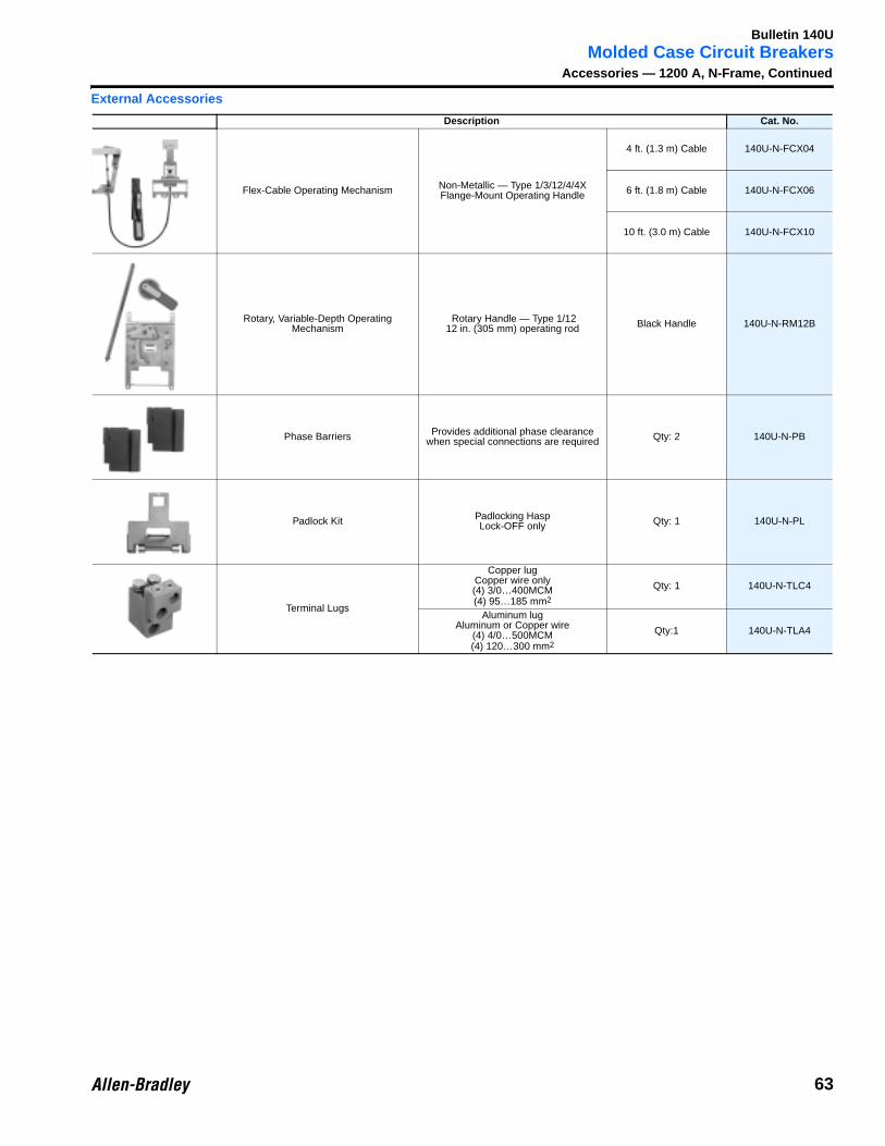
Molded Case Circuit BreakersAccessories — 1200 A, N-Frame, Continued
External Accessories
Description Cat. No.
Flex-Cable Operating Mechanism Non-Metallic — Type 1/3/12/4/4X Flange-Mount Operating Handle
4 ft. (1.3 m) Cable 140U-N-FCX04
6 ft. (1.8 m) Cable 140U-N-FCX06
10 ft. (3.0 m) Cable 140U-N-FCX10
Rotary, Variable-Depth Operating Mechanism
Rotary Handle — Type 1/1212 in. (305 mm) operating rod Black Handle 140U-N-RM12B
Phase Barriers Provides additional phase clearance when special connections are required Qty: 2 140U-N-PB
Padlock Kit Padlocking HaspLock-OFF only Qty: 1 140U-N-PL
Terminal Lugs
Copper lugCopper wire only(4) 3/0…400MCM(4) 95…185 mm2
Qty: 1 140U-N-TLC4
Aluminum lugAluminum or Copper wire
(4) 4/0…500MCM(4) 120…300 mm2
Qty:1 140U-N-TLA4
63

Bulletin 140U
Molded Case Circuit BreakersApproximate Dimensions — 1200 A, N-FrameDimensions are in inches (millimeters). Dimensions are not intended to be used for manufacturing purposes.
Load End
Line End
ON/I
OFF/O
1.062(26.987).531(13.481)
.344(8.738) Dia. Mounting Holes
.703(17.856) Dia. C'Bore4.453(113.106) Deep from Top.594(15.088) Dia C'Bore.359(9.119) Deep from Bottom
.500-13 (12 X 1.75) Tap12-Holes
.250R(6.350)R
.062R(1.575)R
.094R(2.388)R
3.236(82.194)
7.00
0(1
77.7
74)
115.
00(2
92.0
75)
8.62
5(2
19.0
75)
14.7
50(3
74.6
50)
9.25
0(2
34.9
50)
16.0
00(4
06.4
01) .946
(24.022)
.297(7.544)
.750(19.050)
.375(9.525)
1.500(38.100)
Contact Position IndicatorRed-I/ONGreen-O/OFFWhite-TRIPPED
Removable TerminalCover Must Be inPlace While in Service
1.375(34.925)
3.187(80.950)
8.250(209.550)
4.124(104.750)
3.808(96.723)
2.798(71.057)
2.511(63.786)
.312R(7.925)R
11.431(290.348)
Removable T erminalCover Must Be inPlace While in Service
.147 (3.734) Dia. Hole
.500 (12.70) Deep toAccept a #8ThreadCutting Screw6-Places
6.375(161.925)
CL Handle
.188R(4.762)R
1.157(29.388)
.532(13.513)
.062(1.575)
Trough forAttachment Lead
.125 X .750(3.175 X 19.050)Slots forAttachment Leads
2.982(75.743)
1.034(33.281)
.353(6.331)
.375(9.525)
21û±2ûON
3.850R
HandlePivot
0û±2ûTRIPPED
15û±2ûRESET
.062(1.575)
.532(13.513)
1.095(27.813)
3.344(84.938)
5.188(131.769)
5.248(133.293)
5.500(139.687)
6.000(152.400)
7.132(181.146)
AB
13û±2û OFF
3.375(85.725)
2.750 Ref.(69.850) Ref.
2.000(50.800)2.000
(50.800)
1.688(42.863)
1.000(25.400)
1.562(39.687)
.781(19.844)
For 2-Pole Breaker Omit CurrentCarrying Parts from Center Pole
3.906(99.187)
4.875(123.799)
.062(1.588)
R
.062(1.575)
.062(1.588)
R
2.344(59.541)
2.750(69.850)
1.500 Ref(38.100) Ref
C L P
ush
To T
rip
3.819(96.723)
2.493(63.792)
6.375 Ref(161.925) Ref
DimensionsBreaker Status A B
On 7.90 (200.66) 8.30 (210.82)
Tripped 6.50 (165.10) 6.90 (175.26)
Off 5.70 (144.78) 6.10 (154.94)
Reset 5.60 (142.24) 6.00 (152.40)
Handle Forces (At Handle C)On 130 lbs. (58.97 kgs.)
Off 105 lbs. (47.63 kgs.)
Reset 160 lbs. (72.57 kgs.)
L
64
Related Documents