Original Manual B21 Continuous Feeder Preserve for future appliance! Buckle Folding Machine

Welcome message from author
This document is posted to help you gain knowledge. Please leave a comment to let me know what you think about it! Share it to your friends and learn new things together.
Transcript
Original Manual
B21ContinuousFeeder
Preserve for future appliance!
Buckle Folding Machine

Page2Alterations reserved Version 05/2008
Operating Manual B21-C - en
Machine type: Buckle Folding Machine B21
Model: Continuous feeder
Manufacturer: MBO Binder Máquinas Gráficas SARua Joaquim Alves da Silva
Apartado 5093
4456-951 Perafita/Portugal
Tel.: +351 22 998 22 00
Fax: +351 22 998 22 01
Document type:Stand: 13-09-2006 Professional: S. Matos; M. Wiech
Version: 09/06 Language: English
Alterations reserved!
Operating manual/ANSI

Alterations reserved Version 05/2008
Operating Manual B21-C - en
Page 3
PrologueWith the MBO folding machine you have purchased a valuable product. However, it is absolutelyimperative to comply with all Safety Regulations and Safety Instructions. This Operating Manualshould instruct you how to operate correctly the MBO folding machine and to comply with theSafety Regulations and to maintain the machine properly.
Keep this operator manual for future apply at the machine.
CopyrightAll rights reserved.Any use of any of the marks appearing throughout the Products and Services, copy or relay tothird party without the express written consent of MBO-Binder S.A., as appropriate, is strictlyprohibited.
Warranty
Our products are contractually regularized. However, MBO´s warranty does not cover the following:
• Self-assembling/installations and alterations at the machine.• Damages caused biy self-assembling/installations, faulty maintenance and self-repair.• Assembling of spare parts when not purchased from an authorized MBO dealer.• Not definded apply.• Removing of guards or safety devices and resultant damages.
Customer´s information
MBO machines and spare parts can be purchase from our dealers worldwide, also close to you.
For questions, request for technical support or service please contact your dealer.Allways indicate these statements for the sevice orders and spare part orders which can be read-offfrom the machine label.
• Fabrication number• Serial number• Machine type
Use only spare parts, which are supplied or recommended by the manufacturer.

Page4Alterations reserved Version 05/2008
Operating Manual B21-C - en
Alterations reserved Version 05/2008
Operating Manual B21-C - en
Page 5
Indice
1 General ....................................................................................... 9
1.1 Content and diagram conventions............................................................... 9
1.2 Important references to the operating manual .......................................... 91.2.1 Marking of the product ..................................................................................... 101.2.2 Working area ................................................................................................... 10
1.3 Product data .................................................................................................. 111.3.1 Floor plan B21/44X ........................................................................................... 111.3.2 Floor plan B21/64X .......................................................................................... 11
1.4 Technical Data ............................................................................................... 12
1.5 Supplyed documents .................................................................................... 13
1.6 Equipment ...................................................................................................... 141.6.1 Buckle folding machine .................................................................................... 141.6.2 Folding unit one ............................................................................................... 141.6.3 Folding unit two ............................................................................................... 141.6.4 Knife folding unit „X“ ......................................................................................... 141.6.5 Hook on stream delivery ................................................................................... 14
1.7 Functioning description ................................................................................ 151.7.1 Functioning description buckle fold .................................................................. 151.7.2 Functioning description knife fold ..................................................................... 15
2 Safety ......................................................................................... 17
2.1 Representation of alerts ............................................................................... 172.2.1 Safety references and colours .......................................................................... 172.1.2 General dangers signs ..................................................................................... 182.1.3 Danger level ..................................................................................................... 202.1.4 Safety advises at the operators manual ............................................................ 212.1.5 Dangerous zones / Warning signs at the machine ........................................... 25
2.2 Product security ............................................................................................. 332.2.1 Obligation and liability ...................................................................................... 332.2.2 Due use ........................................................................................................... 342.2.3 Inappropriate use is: ........................................................................................ 34
2.3 Protection guard -general plan .................................................................... 352.3.1 Protection guard - general plan of machine ...................................................... 352.3.2 Protection guard list 8 and 16pg unit ................................................................ 362.3.3 Protection guard list knife folding unit „X“ .......................................................... 372.3.4 Protection guard list Delivery A56 ..................................................................... 38
2.4 Organisational and personnel ..................................................................... 392.4.1 Working safety ................................................................................................. 392.4.2 Demands on the operating personnel ............................................................... 392.4.3 Qualification and training .................................................................................. 39

Page6Alterations reserved Version 05/2008
Operating Manual B21-C - en2.5 Personal protection equuipment ................................................................. 40
2.6 Tasks for Emergency ..................................................................................... 402.6.1 Rescue of persons ........................................................................................... 402.6.2 Emerging substances ...................................................................................... 41
3.0 Transportation, assembly and installation .............................. 42
3.1 Transportation ............................................................................................... 423.1.1 Feeder ............................................................................................................. 423.1.2 Parallel unit ...................................................................................................... 433.1.3 8 and 16pg unit ................................................................................................ 433.1.4 Mobile knife folding unit “X” ............................................................................... 443.1.5 Mobile stream delivery ..................................................................................... 44
3.2 Assembly and installation of machine..................................... 45
3.3 Electrical connection .................................................................................... 453.3.1 Control cabinet ................................................................................................. 473.3.2 Main current connection ................................................................................... 473.3.3 Stream delivery ................................................................................................ 47
4.0 Maintenance .............................................................................. 48
4.1 Tensioning or exchange of belts/tapes ....................................................... 494.1.1 Upper feeder transport tape .............................................................................. 494.1.2 Lower feeder transport tape .............................................................................. 494.1.3 Feeder chain .................................................................................................... 504.1.4 Alignment tape at register table ....................................................................... 504.1.5 Drive belt for suction wheel ............................................................................... 514.1.6 Drive belt for foldrollers and slitter shaft at parallel unit ..................................... 514.1.7 Main drive of parallel unit .................................................................................. 514.1.8 Drive belt for foldrollers at parallel unit and slitter shafts at subsequent unit ...... 524.1.9 Drive belt at register table of following folding unit ............................................. 524.1.10 Drive belt for foldrollers and slitter shafts of knife folding unit “X” ....................... 534.1.11 Setting of air gap for knife coupling of knife folding unit “X” ................................ 53
4.2 Lubrication / Cleaning .................................................................................. 544.2.1 Main machine including register table .............................................................. 544.2.2 Continuous feeder F ......................................................................................... 544.2.3 Guides of pressure bars / Bearings of foldrollers .............................................. 544.2.4 Coupling of knife folding unit “X” ........................................................................ 554.2.5 Guide rails / sheet stop (knife folding unit “X”) .................................................. 554.2.6 Cleaning of foldrollers ....................................................................................... 554.2.7 Compressor ..................................................................................................... 56

Alterations reserved Version 05/2008
Operating Manual B21-C - en
Page 7
5.0 Operation of the machine ......................................................... 57
B 1.0 Main control panel ........................................................................................ 58
B 2.0 Continuous feeder C ..................................................................................... 592.1 Generally settings ............................................................................................ 59
2.2 Air support ..................................................................................................... 60
2.3 Transportation system - ventilation .............................................................. 61
2.4 Suction wheel ............................................................................................... 64
2.5 Vacu-Infeed (Option) ..................................................................................... 65
B 3.0 Register table with ball rail, double sheet control, sheet infeedcontrol .................................................................................................... 66
3.1 Ball rail .......................................................................................................... 663.1.1 Vacu-Alignment (Option) .................................................................................. 67
3.2 Double sheet control ..................................................................................... 69
3.3 Sheet infeed .................................................................................................. 69
B 4.0 Parallel folding unit ................................................................... 70
4.1 Setting of foldrollers ..................................................................................... 70
4.2 Buckle plates ................................................................................................. 71
4.3 Deflectors ....................................................................................................... 72
4.4 Combi buckle plates FTK (Option) .............................................................. 73
B 5.0 Slitter shafts............................................................................... 74
5.1 Perforating ..................................................................................................... 74
5.2 Special perforating knife (Option) ............................................................... 75
5.3 Cutting ............................................................................................................ 75
5.4 Scoring ........................................................................................................... 75
5.5 Gully cut ......................................................................................................... 76
5.6 Edge trimming ............................................................................................... 77
5.7 Slitter shaft guard .......................................................................................... 78
B 6.0 Mobile buckle folding unit ........................................................ 79
6.1 Installation ..................................................................................................... 79
6.2 Setting and sheet transportation ................................................................. 79
6.3 Electrical connection .................................................................................... 80
6.4 Control panel ................................................................................................. 80
6.5 Foldrollers and slitter shafts at subsequent folding units .......................... 80

Page8Alterations reserved Version 05/2008
Operating Manual B21-C - enB 7.0 Mobile knife folding unit “X” .................................................... 81
7.1 Installation ..................................................................................................... 81
7.2 Electrical connection .................................................................................... 81
7.3 Setting and sheet transportation ................................................................. 827.3.1 Knife folding unit “X” as first crossfold ............................................................... 827.3.2 Knife folding unit “X” as 2nd crossfold (threefold) .............................................. 847.3.3 Foldrollers / Slitter shafts of the knife folding unit “X” ........................................ 847.3.4 Knife setting ..................................................................................................... 85
B 8.0 Noise damping device .............................................................. 87
B 9.0 Stream delivery ......................................................................... 88
9.1 Mobile stream delivery A56 .......................................................................... 88
9.2 Hook-on stream delivery SE500/3 ................................................................ 89
D10.0 Instructions to the use .............................................................. 90
D10.1 Setting instructions for the most commonly folds ...................................... 9010.1.1 Parallelfold ....................................................................................................... 9010.1.2 Crossfold ......................................................................................................... 9210.1.3 Threefold .......................................................................................................... 93
M 1.0 Installation instruction .............................................................. 94
1.1 Conveyer table for unit “X” .......................................................................... 94
M2.0 Maintenance protocol ............................................................... 95
M 3.0 Pulley and belt drive ................................................................. 96
M 4.0 Out of order........................................................................................100
4.1 Statements for the storage ........................................................................... 100
4.2 Environment and disposal ............................................................................ 100
4.3 Disposal of the old machine ......................................................................... 1014.3.1 Disposal with order at the supplier ................................................................... 1014.3.2 Disposal with order at a disposal and wrecking ................................................ 1014.3.3 Disposal over the own firm ............................................................................... 101
4.4 Ground-water protection .............................................................................. 101

Alterations reserved Version 05/2008
Operating Manual B21-C - en
Page 9
1 General
1.1 Content and diagram conventions
That construct organizes itself this user information in:
Chapter 1: General
Chapter 2: Safety
Chapter 3: Transportation/Set up/Installation
Chapter 4: Adjustment/Setup
Chapter 5: Operation
Chapter 6: Out of order
the sequnce of these chapters enables you a uniformly progressive trained success with theunse of the machine. The single chapters gives first a surveyover the subject handled, goingprogressively into detail.
Working hint and information:
This sign marks information that seve the securityand the protection of themachine.
This sign marks information for procedure, that guarantee a simple andhelpful mode of operation.
1.2 Important references to the operating manual
The existing user information is aligned on the operator of the machine. It should make the operatortrusted with the operation method, operating mode, security references and the maintenance of thismachine.
This user information is a part of your product. It must be stored during the service life of the productat the machine. Give this instruction to each following owner or user of the product.
Keep this user information allways updated. Introduce every update in this document.
Our machine corresponds at the moment of delivery to the newest state of technology. As we workpermanently at further developments, we reserve ourselves changes.
User judgment of the operating instructions:Our operating instructions are regularly updated. Help us with your proposals to form user-friendlyoperating instructions.

Page10Alterations reserved Version 05/2008
Operating Manual B21-C - en1.2.1 Marking of the product
The identification of the machine as well as the most important machines data can be seen at themachine in the type sign (1).
Allways indicate these statements for the sevice orders and spare part orders:
• Fabrication number• Serial number• Machine type
1.2.2 Working area
The represented graphics show the single working area of the machine. The permitted work fieldduring the operation is marked in grey.
1
Alterations reserved Version 05/2008
Operating Manual B21-C - en
Page 11
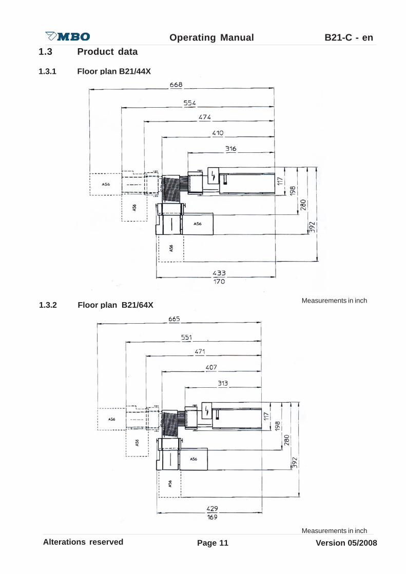
1.3 Product data
1.3.1 Floor plan B21/44X
1.3.2 Floor plan B21/64X Measurements in inch
Measurements in inch
Page12Alterations reserved Version 05/2008
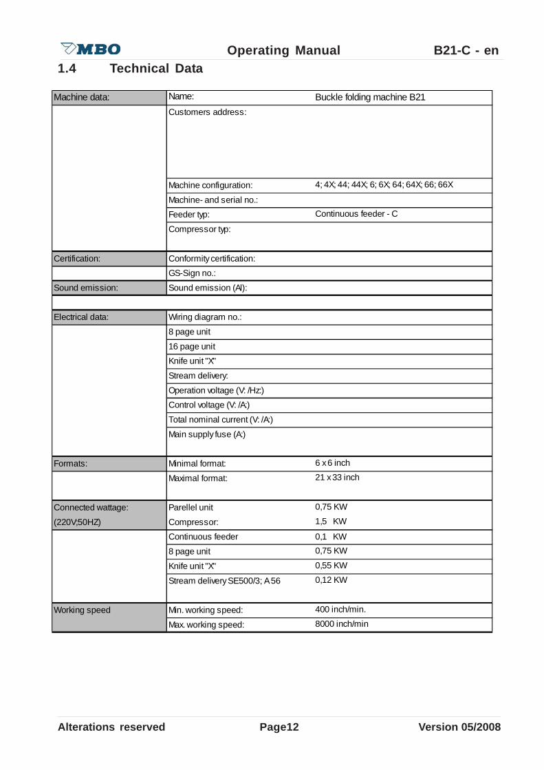
Operating Manual B21-C - en1.4 Technical Data
Machine data: Name:Customers address:
Machine configuration:
Machine- and serial no.:Feeder typ:
Compressor typ:
Certification: Conformity certification:GS-Sign no.:
Sound emission: Sound emission (Al):
Electrical data: Wiring diagram no.:
8 page unit
16 page unitKnife unit "X"
Stream delivery:
Operation voltage (V: /Hz:)Control voltage (V: /A:)
Total nominal current (V: /A:)
Main supply fuse (A:)
Formats: Minimal format:
Maximal format:
Connected wattage: Parellel unit
(220V;50HZ) Compressor:Continuous feeder 0,1 KW
8 page unit
Knife unit "X"
Stream delivery SE500/3; A 56
Working speed Min. working speed:
Max. working speed:
4; 4X; 44; 44X; 6; 6X; 64; 64X; 66; 66X
Continuous feeder - C
Buckle folding machine B21
0,75 KW
0,75 KW
0,55 KW
6 x 6 inch21 x 33 inch
1,5 KW
8000 inch/min
0,12 KW
400 inch/min.

Alterations reserved Version 05/2008
Operating Manual B21-C - en
Page 13
1.5 Supplyed documents
Users manual: Counter:Air producer:Sequence station:
Wiring diagram no.: Machine:Sequence station:
Spare parts manual: Machine: B21 Continuous feederKnife unit "X": B21 Stream delivery: SE 500/3 / A56Sequence unit:
Knife list: TM 35/2
Net lbs Brut lbs
Weight in lbs: Continuous feeder 4 buckles 1219 1585Continuous feeder 6 buckles 1234 1600
Parallel unit 4 buckles with noise hood 990 1631
Parallel unit 4 buckles without noise hood
Parallel unit 6 buckles with noise hood 1047 1752
Parallel unit 6 buckles without noise hood
8pg 4 buckle unit with noise hood
8pg 4 buckle unit without noise hood
8pg 6 buckle unit with noise hood
8pg 6 buckle unit without noise hood
Knife unit "X" T530-4X 595 881
Knife unit "X" T530-44X 637 926
Stream delivery SE 500/3 79 235
Stream delivery A56 218 383

Page14Alterations reserved Version 05/2008
Operating Manual B21-C - en1.6 Equipment
1.6.1 Buckle folding machine
The buckle folding machine works exclusively in accordance with the principle of buckle folding.The MBO buckle folding machine B21 with pile feeder has been developed to process sheets inthe sizes of 6 x 6 inch up to 21 x 33 inch. The production speed can be regulated between 400and 8000 inch/min. However, this result depends on the type and size of sheet and type of fold.
The basic machine consists of a folding unit one with pile feeder as well as the well-proven MBOregister table.
1.6.2 Folding unit one
The folding unit one is equipped with four (optional six) stainless-steel buckle plates, sheet stopfine adjustment and integrated swing deflectors. Moreover, it is also equipped with the well-provenMBO spiral foldrollers, which may be adjusted through the quick-setting elements located on topof the machine, combined with the low-noise belt drive system and solid, quickly removeableslitter shafts through plug bearings.
1.6.3 Folding unit two
The folding unit two is a mobile buckle folding unit with own drive, register table, a maximumworking width of 21 inch as well as four buckle plates as descriped above.
1.6.4 Knife folding unit „X“
The knife folding unit “X”, which is equipped with belt drive system, maximum working width of21inch, and electronical knife control is useable as a folding unit two or three.The knife folding unit “X” has an own drive and self-control.
1.6.5 Hook on stream delivery
The hook-on stream delivery SE500/3 is available in the configurations B21/4 ; B21/6 ; B21/44 ;B21/64; B21/66 as standard. The mobile delivery A56 is optional. Machines with a unit ”X”configuration, 4X ; 6X ; 44X; 64 or 66X, must choose the optional A56 ,because SE500/3 cannot be suspended at the ”X” unit.
The following description from the feeder to the machine should enable the operator to achieve ageneral understanding of the machine.

Alterations reserved Version 05/2008
Operating Manual B21-C - en
Page 15
1.7 Functioning description
1.7.1 Functioning description buckle fold
The principle of buckle fold is thatthe sheet is always pushed intothe buckle plate.
three foldrollers and one buckle plateare necessary to prepare a buckle fold.Foldrollers 1 and 2 carry the sheet intothe buckle plate 4 to the sheet stop.
A buckle occurs during transporationthrough these foldrollers to the directionof foldrollers 2 and 3 by which the sheetis folded through its passage.
1.7.2 Functioning description knife fold
Two foldrollers 1 und 2 as wellas one knife 3 are necessaryto prepare aknife fold.
The sheet is transported underthe knife to a sheet stop and aligned.
After the knife has been releasedit moves the sheet betweenthe foldrollers where it is foldedduring its passage.
4
3
2 1

Page16Alterations reserved Version 05/2008
Operating Manual B21-C - en
Alterations reserved Version 05/2008
Operating Manual B21-C - en
Page 17
2 Safety
2.1 Representation of alerts
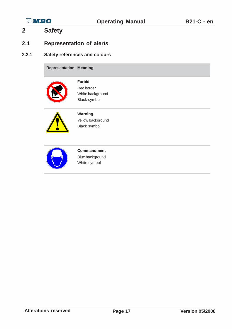
2.2.1 Safety references and colours
Representation Meaning
ForbidRed borderWhite backgroundBlack symbol
WarningYellow backgroundBlack symbol
CommandmentBlue backgroundWhite symbol

Page18Alterations reserved Version 05/2008
Operating Manual B21-C - en2.1.2 General dangers signs
Representation Meaning
Warning of hot surface
Warning of falling objects
Warning of rotating machine parts
Warning of hand injuries
Warning of dangerous electric tension
Caution, danger through stumble places
Caution, lifting of heavy machine parts
Caution, danger through rotating slitter shafts
Caution, danger through rotating chain drive
Alterations reserved Version 05/2008
Operating Manual B21-C - en
Page 19
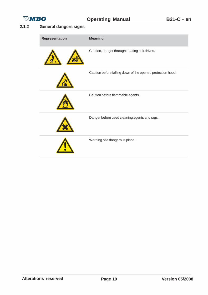
2.1.2 General dangers signs
Representation Meaning
Caution, danger through rotating belt drives.
Caution before falling down of the opened protection hood.
Caution before flammable agents.
Danger before used cleaning agents and rags.
Warning of a dangerous place.

Page20Alterations reserved Version 05/2008
Operating Manual B21-C - en2.1.3 Danger level
Danger level give a reference to the heavy of the danger. They are constructed after a classificationsystem, which differs through different signal words:
• Danger (Safety signs presented)• Warning (Safety signs presented)• Caution (Safety signs presented)• Caution (without Safety signs)
Danger levels Meaning
A directly threatening danger that leads to heavy injuries or to death.
A possibly dangerous situation that can lead to heavy injuries or todeath.
A possible dangerous situation that can lead to easy personal injury.
A possible dangerous situation that can lead to material damage.

Alterations reserved Version 05/2008
Operating Manual B21-C - en
Page 21
2.1.4 Safety advises at the operators manual
Danger of electric tension.Negligence can cause, heavy injuries or death.Report damaged electrical connections to respnsible supervisor.
Danger of electric tension at head clams with main switch off.Negligence can cause, heavy injuries or death.Work at the electronics can only be carried out of authorized persons orskilled personnel.
Danger of electric tension.Negligence can cause, heavy injuries or death.• Keep the main control cabinet and the lower distributor cabinet always
locked against unauthorized persons.• During maintenance working at the control cabinet turn off main switch
and disconnect the network connector.• Turn off and lock out system power before servicing.
Danger before running belt-drive.Negligence can cause, bruise emerges at the hands.This work should be carried out by one person only !
Danger of running machine parts.Negligence can cause heavy personal injuries or extensive damages.Report each audible/visible security-related change of the machine to theresponsible for that in your business.

Page22Alterations reserved Version 05/2008
Operating Manual B21-C - en
Danger before falling down of the opened protection hood.Negligence can cause heavy injuries through bruise of body part.Be sure that in work with opened noise hoods this is completely opened tothe attack.
Danger of stumble places through lying around cables.Negligence can cause personal injuries.Place the machines connections (cables, hoses, tubes) so, that they formno stumble places.
Danger of running machines part.Negligence can cause, heavy injuries or death.• Keep hairs always together bandage and protected.• Take by operation and maintenance working at the machine your
jewellery off.• Carry during operation or maintenance on the machine only adjoining
garment.
Danger of sound pressure.Negligence can cause, ear damage can emerge.Use an ear protection for work at the folding machine.
Danger of running machines part.Negligence can cause, heavy injuries or death.In sudden stop of the machine, review before turning on:• That no further person is at the machine.• That the machine is in a flawless condition.

Alterations reserved Version 05/2008
Operating Manual B21-C - en
Page 23
Danger of running machine parts.Negligence can cause heavy personal injuries or extensive damages.• Safety switches at the protection and noise hoods can not be
manipulated or modified.• Adjustments by opened protection hoods are only permited for
setup. Setups can only be performed on machines with electronicalspeed regulation.
• Machines with mecanical speed regulation can only be adjusted withopened protection hoods throught the hand wheel.
Danger of running machine parts during the installation work.Negligence can cause heavy personal injuries or extensive damages.• Allow service and cleaning works only to be carryed.• Turn off the machine during maintenance and restoration work by the
main switch.• Neutralize the electrical cabinet against unintentional switch on.• Check before turning on, that no further person is at the machine.
Danger through heavy machines components.Negligence can cause heavy personal injuries or extensive damages.If the weight amounts more than 25 kg, a further person must be aid fortaken of the components.
Danger through maintenance tool.Negligence can cause heavy personal injuries or extensive damages.• Use only tools in good working condition.• Pay attention that after adjustment or maintenance working at the
machine, all tools are removed.

Page24Alterations reserved Version 05/2008
Operating Manual B21-C - en
Danger before wrong use of cleansing agents.Negligence can cause health defects.• Avoid skin contact.• Protect yourself against splashes in the eyes.• Use for cleansing protection gloves.• Inform yourself through the cleaner manufacturer about remaining
dangers and compatibility for human skin.
Danger of slitter shafts.Negligence can cause cut injuries.• During maintenance work at the slitter shafts, the use of
protection gloves and safteyshoes is required.• Do not hold the slitter shafts by the tool but always at the
shaft.
Danger before used cleansing rags.Negligence can cause health defects.• Note the fire dangers through the flammability of the cleaner.• Detoxifythe cleaning rags.• Inform yourself at the cleaner manufacturer about remaining dangers as
well as over the correct disposal.
Danger of running machines part during the installation working.Negligence can cause heavy personal injuries or extensive damages.• Never grasp into the running machine in!• Keep protection hood close during production.
Alterations reserved Version 05/2008
Operating Manual B21-C - en
Page 25
2.1.5 Dangerous zones / Warning signs at the machine
2.1.5.1 Overview
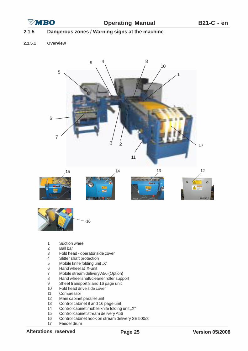
1 Suction wheel2 Ball bar3 Fold head - operator side cover4 Slitter shaft protection5 Mobile knife folding unit „X“6 Hand wheel at X-unit7 Mobile stream delivery A56 (Option)8 Hand wheel shaft/cleaner roller support9 Sheet transport 8 and 16 page unit10 Fold head drive side cover11 Compressor12 Main cabinet parallel unit13 Control cabinet 8 and 16 page unit14 Control cabinet mobile knife folding unit „X“15 Control cabinet stream delivery A5616 Control cabinet hook on stream delivery SE 500/317 Feeder drum
14 12
16
1315
15
6
72
11
4 810
9
3 17
Page26Alterations reserved Version 05/2008
Operating Manual B21-C - en2.1.5.2 Danger references-arrangement and meaning
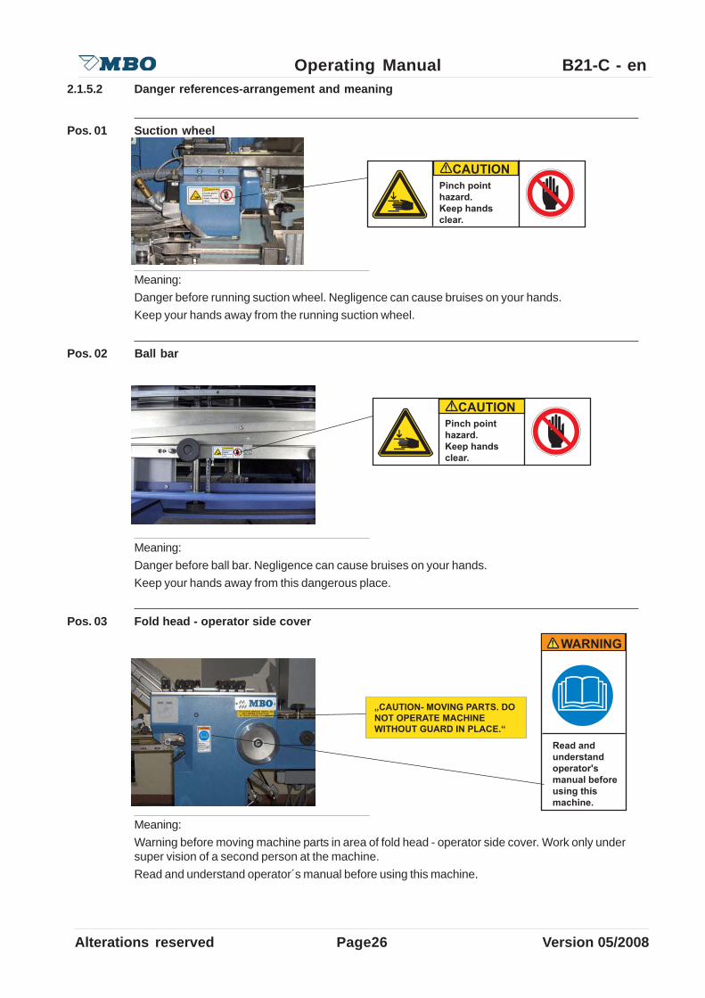
Pos. 01 Suction wheel
Meaning:Danger before running suction wheel. Negligence can cause bruises on your hands.Keep your hands away from the running suction wheel.
Pos. 02 Ball bar
Meaning:Danger before ball bar. Negligence can cause bruises on your hands.Keep your hands away from this dangerous place.
Pos. 03 Fold head - operator side cover
Meaning:Warning before moving machine parts in area of fold head - operator side cover. Work only undersuper vision of a second person at the machine.Read and understand operator´s manual before using this machine.

Alterations reserved Version 05/2008
Operating Manual B21-C - en
Page 27
Pos.04 Slitter shaft protection
Meaning:Danger before rotating slitter shafts. Negligence can cause cut or tear off of body parts.Lock out power and allow machine to stop before opening.
Pos.05 Mobile knife folding unit „X“
Meaning:Read and understand operator´s manual before using this machine.
Meaning:Danger before rotating slitter shafts. Negligence can cause cut or tear off of body parts.Lock out power and allow machine to stop before opening.

Page28Alterations reserved Version 05/2008
Operating Manual B21-C - en
Pos. 06 Hand grip at X-Unit
Meaning:Danger before material damages.Operate X-Unit only with locked hand grip.
Pos.07 Mobile stream delivery A76
Meaning:Read and understand operator´s manual before using this machine.

Alterations reserved Version 05/2008
Operating Manual B21-C - en
Page 29
Pos.08 Hand wheel shaft/cleaner roller support
Meaning Pos. 1Danger before rotating machine shafts. Negligence can cause cut or tear off of body parts.Keep your hands clear of rollers.
Meaning Pos. 2Danger before rotating slitter shafts. Negligence can cause cut or tear off of body parts.Lock out power and allow machine to stop before opening.
1
1
2
1
1
Pos. 1 Pos. 2
Page30Alterations reserved Version 05/2008
Operating Manual B21-C - en
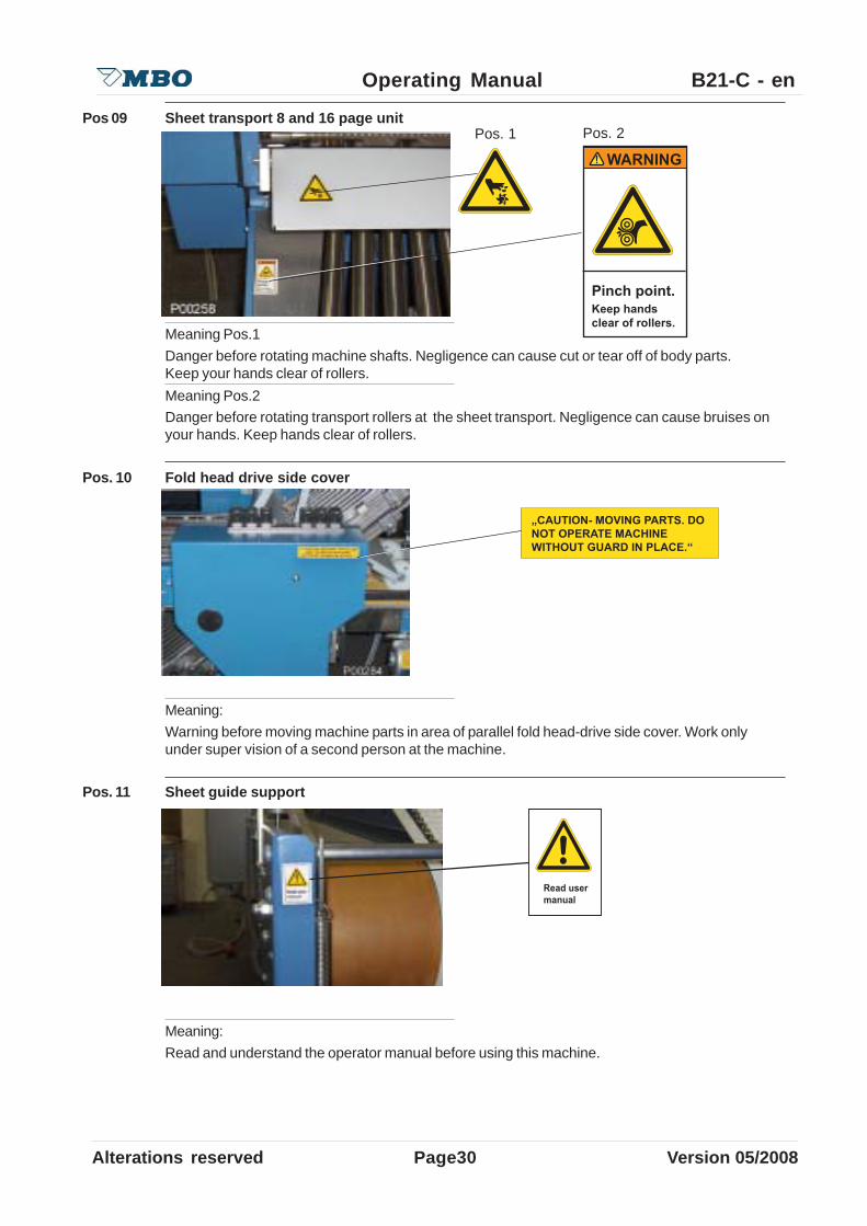
Pos 09 Sheet transport 8 and 16 page unit
Meaning Pos.1Danger before rotating machine shafts. Negligence can cause cut or tear off of body parts.Keep your hands clear of rollers.Meaning Pos.2Danger before rotating transport rollers at the sheet transport. Negligence can cause bruises onyour hands. Keep hands clear of rollers.
Pos. 10 Fold head drive side cover
Meaning:Warning before moving machine parts in area of parallel fold head-drive side cover. Work onlyunder super vision of a second person at the machine.
Pos. 11 Sheet guide support
Meaning:Read and understand the operator manual before using this machine.
Pos. 2Pos. 1

Alterations reserved Version 05/2008
Operating Manual B21-C - en
Page 31
Pos. 12 Main cabinet parallel unit
Meaning Pos.1 und Pos. 2:Hazardous voltage. Negligence can cause electric shock or burn.Turn off and lock out system power before servicing.Meaning Pos.3:Replacement of fuses only with same specification.Meaning Pos.4:Use copper wire only!
Pos. 13 Control cabinet 8 and 16 page unit
Meaning:Hazardous voltage. Negligence can cause electric shock or burn.Turn off and lock out system power before servicing.
Pos.4
Pos.1
Pos.2
Pos.3

Page32Alterations reserved Version 05/2008
Operating Manual B21-C - en
Pos. 14 Control cabinet mobile knife folding unit „X“
Meaning:Hazardous voltage. Negligence can cause electric shock or burn.Turn off and lock out system power before servicing.
Pos.15 Control cabinet stream delivery A56
Meaning:Hazardous voltage. Negligence can cause electric shock or burn.Turn off and lock out system power before servicing.
Pos. 16 Control cabinet hook on stream delivery SE 500/3
Meaning:Hazardous voltage. Negligence can cause electric shock or burn.Turn off and lock out system power before servicing.
Alterations reserved Version 05/2008
Operating Manual B21-C - en
Page 33
2.2 Product security
2.2.1 Obligation and liability
Note references in the operation instructions:
Prerequisite for safety and free interference working with this machine is the knowledge of thebasic safety references and the safety prescript.
This operating instruction is to be noted by all persons, who work at the machine. In addition all rulesvalid for accident prevention has to be noted.
Potential danger while operating with machine:
The Buckle folding machine is after the state of the technology and that acknowledged safetyrules constructed. Nevertheless dangers for body and life of the unser or third and/or inpairmentcan emerge in its use at the machine or at other material asset.
The machine is to be used only:
• For the due use• In safety flawless condition
Interferences, which can impair the safety, are to be removed immediately.
Guarantee and liability
Herefor our general sale and delivery conditions has to be concerned. The Guarantee and liabilityclaims with personal injuries and equipment damages are not excluded if they are to be led back toone or several of the following causes:
• Due use of the machine,• Improber installation, do into operation, serving and maintenance of the machine,• Operating of the machine in defective safety arrangements or not regular appropriate or not
operable safety devices and protection devices,• Not following of the references in the operating instructions regarding carrier, storage,
assembling, starting, operating, maintenance and mobilizing of the machine,• Independent structural variations at the machine,• The not keeping of maintenance and cleaning intervals that exclude a standstill of the
machine,• Deficient supervision of machines part, that a wear be subject,• Bad servicing and damages through foreign objects.

Page34Alterations reserved Version 05/2008
Operating Manual B21-C - en2.2.2 Due use
• The machine is intended only for the folding, designing, perforating and cutting of paper.• The machine is displayed only for the one-man-operation.• The machine can only be operated in a flawless technical condition. Interferences, which
endanger the safety, must immediately be removed by instructed persons or frommanufacturer or from supplier.
• The machine can only be operated of seviced by skilled and autorized personnel. Machine canonly be operated/serviced by persons older than 18 years.
2.2.3 Inappropriate use is:
• An other use of the machine as folding, designing, perforating and cuttting of paper.• Working of other materials as a paper.• Manipulating and independent modification of the machine.• Removing of protection and safety devices from the machine.• Operating of the machine without instructed or trained personal.• Operating / maintenance by persons younger than 18 years.• Operating of the machine without instructed or trained personel.
The manufacturer and/or supplier is not responsible for all damages, that develop from inappropriateuse.

Alterations reserved Version 05/2008
Operating Manual B21-C - en
Page 35
2.3 Protection guard -general plan
2.3.1 Protection guard - general plan of machine
1
3
2
4
6
7
8 12
16
15141311
510
9
1617
Page36Alterations reserved Version 05/2008
Operating Manual B21-C - en
1
2
3
4
5
6
7
10 9
8
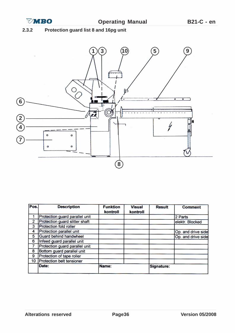
2.3.2 Protection guard list 8 and 16pg unit
Alterations reserved Version 05/2008
Operating Manual B21-C - en
Page 37
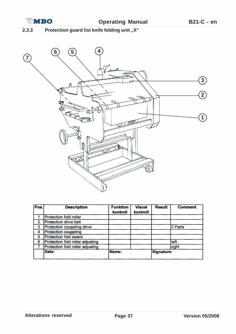
2.3.3 Protection guard list knife folding unit „X“
1
2
3
4567

Page38Alterations reserved Version 05/2008
Operating Manual B21-C - en2.3.4 Protection guard list Delivery A56
1
3
2

Alterations reserved Version 05/2008
Operating Manual B21-C - en
Page 39
2.4 Organisational and personnel
2.4.1 Working safety
• Preserve the operationg instructions manual permanently at the machine regarding to theoperating instructions the universally valid local regulations to the accident prevention and tothe environmental protection.
• Keep all safety references and dangers references at the machine in readable conditions.• Review the safety references and dangers references occasionally.
2.4.2 Demands on the operating personnel
This table represents the jurisdictions and the different activities of person groups, which work atthe machine.
2.4.3 Qualification and training
Ensure that the operating personal was trained with the machine and that the operating manualwas read. A correct operating of the machine can prevent severe injuries to the operator and thirdpersons as well as material damages.
Attend to following references:
• Permit only trained and on manner personnel work at the machine.• The user information must be read and understood by the operating and maintenance
personnel.• Determine clearly the responsibility of the personnel for operating, converting and
maintenance.• Let only trained personnel work at the machine under supervision of a trained person.• Instruction must be receipt in written form.
Inst
ruct
ed
Per
sons
Mec
hani
c fir
m
Cus
tom
er s
ervi
ce
Res
pons
able
su
perv
isor
Transport and packing
Starting
Operation
Troubleshooting mechanically
Interference removal electrically
Arrange, mobilizing
Maintenance
Restoration
Out of order, storage
Page40Alterations reserved Version 05/2008
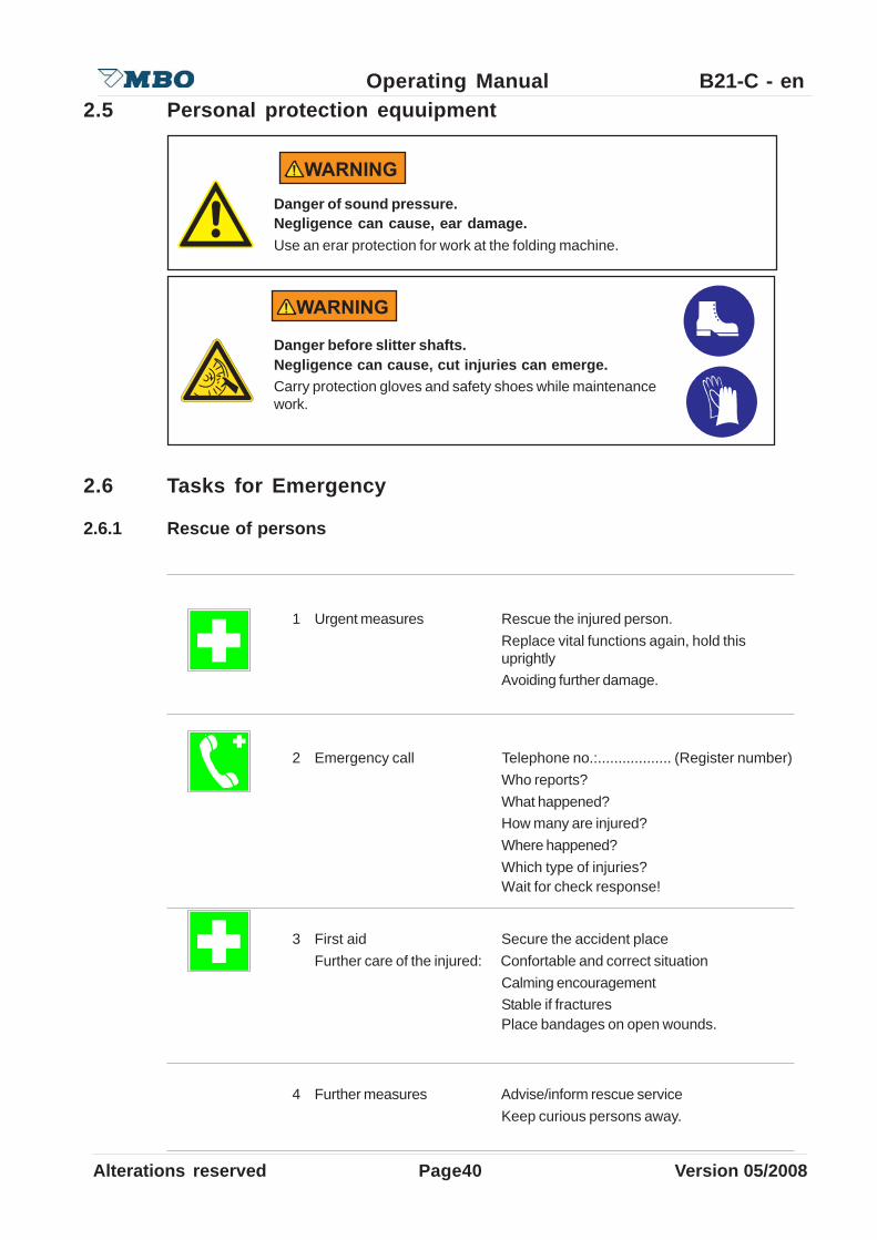
Operating Manual B21-C - en2.5 Personal protection equuipment
2.6 Tasks for Emergency
2.6.1 Rescue of persons
1 Urgent measures Rescue the injured person.Replace vital functions again, hold thisuprightlyAvoiding further damage.
2 Emergency call Telephone no.:.................. (Register number)Who reports?What happened?How many are injured?Where happened?Which type of injuries?Wait for check response!
3 First aid Secure the accident placeFurther care of the injured: Confortable and correct situation
Calming encouragementStable if fracturesPlace bandages on open wounds.
4 Further measures Advise/inform rescue serviceKeep curious persons away.
Danger of sound pressure.Negligence can cause, ear damage.Use an erar protection for work at the folding machine.
Danger before slitter shafts.Negligence can cause, cut injuries can emerge.Carry protection gloves and safety shoes while maintenancework.

Alterations reserved Version 05/2008
Operating Manual B21-C - en
Page 41
2.6.2 Emerging substances
Concern the factory directives with its statements in the fire case. Depend on the given directions.Is this not by hand advance so:
2.6.2.1 Solvent degreasing out of hydrocarbons
• Inform superior.• Emerging of the material: in larger quantities supply immediately for fresh air and leave the
location.• Slight spill quantities absolve with allocated binding agent.• In case of fire extinguish only with extinguisher located to this.• Notify immediately First helper and supervisor.• Wash off in skin contact with much water and skin cleaner.• By eye contact rise with much water (eye shower).• After inhaling of softening, reach for fresh air.• Carry unconscious persons immediately to the fresh air.
2.6.2.2 Inflammable degreasing solvents out of not water mixable hydrocarbons (ex. petroleum,test gasoline, Naphtene: Cyclohexan)
• Disengage inflammation of the material: Unit, leave dangers area and inform layer master.• Use extinguish: Coal dioxide (CO2), foam, powder extinguisher or water as spray ray.• Leakage: Slight spill quantities absolve with allocated binding agent.• Gather remainder materials and refuse in containers planned for that.• Eyes: Rise immediately with much water at least 10 minutes and search for physician.• Skin: Rise concerned skin place with much water.• Inhaling: Worry immediately for fresh air. Keep quietly and hold warm search for physician.• Swallowing: Search immediately for medical help.
2.6.2.3 Cleaner with watery alkaline cleaning solution:
• Leakage: Inform superior. Spill quantities absolve with allocated binding agent. Clean slightquantities with much water.
• Accidents: Inform first helper and superior.• Irritation of skin or eyes rise with much water.• In swallowing of the concentrate rise mouth drink much water.• Search for after swallowing of concentrate or continuous irritation medical help.
2.6.2.4 Cleaner BG5-9, weakly alkaline:
• Leakage: Neutralize of initiating running out of little quantities into the discharge channel.• Eyes: Rise immediately with a lot water at least 10 minutes and search for physician.• Skin: Rise concerned skin with a lot water.• Inhaling: Go immediately for fresh air. Keep calm and hold warm and contact medical
assistance.• Swallowing: Immediately contact medical assistance and show label safety data sheet.
Page42Alterations reserved Version 05/2008
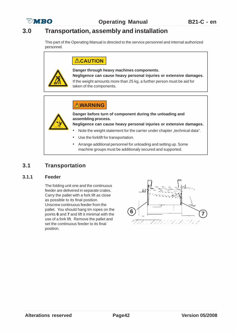
Operating Manual B21-C - en3.0 Transportation, assembly and installation
This part of the Operating Manual is directed to the service personnel and internal authorizedpersonnel.
3.1 Transportation
3.1.1 Feeder
The folding unit one and the continuousfeeder are delivered in separate crates.Carry the pallet with a fork lift as closeas possible to its final position.Unscrew continuous feeder from thepallet. You should hang tm ropes on thepoints 6 and 7 and lift it minimal with theuse of a fork lift. Remove the pallet andset the continuous feeder to its finalposition.
Danger through heavy machines components.Negligence can cause heavy personal injuries or extensive damages.If the weight amounts more than 25 kg, a further person must be aid fortaken of the components.
Danger before turn of component during the unloading andassembling process.Negligence can cause heavy personal injuries or extensive damages.• Note the weight statement for the carrier under chapter „technical data“.
• Use the forklift for transportation.
• Arrange additional personnel for unloading and setting up. Somemachine groups must be additionaly secured and supported.
6 7
Alterations reserved Version 05/2008
Operating Manual B21-C - en
Page 43
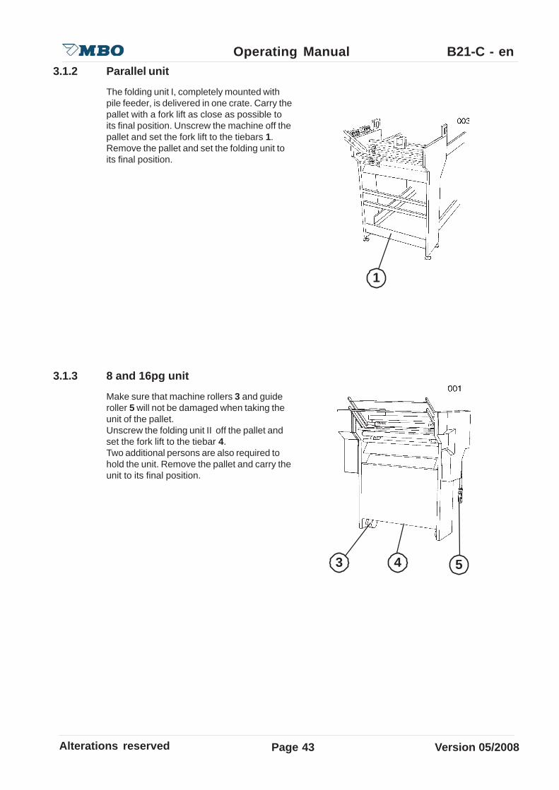
3.1.2 Parallel unit
The folding unit I, completely mounted withpile feeder, is delivered in one crate. Carry thepallet with a fork lift as close as possible toits final position. Unscrew the machine off thepallet and set the fork lift to the tiebars 1.Remove the pallet and set the folding unit toits final position.
3.1.3 8 and 16pg unit
Make sure that machine rollers 3 and guideroller 5 will not be damaged when taking theunit of the pallet.Unscrew the folding unit II off the pallet andset the fork lift to the tiebar 4.Two additional persons are also required tohold the unit. Remove the pallet and carry theunit to its final position.
1
3 4 5

Page44Alterations reserved Version 05/2008
Operating Manual B21-C - en
A56
3.1.4 Mobile knife folding unit “X”
Unscrew the knife folding unit “X” off thepallet, set the fork lift onto the frame 1,and remove the pallet. Affix the four guidewheels 2 and let the knife folding unitcarefully down
3.1.5 Mobile stream delivery
Unscrew the stream delivery and lift itwith two additional persons off the pallet.
Clean all machine parts (folding units and deliveries) with rust preventing agents!
Danger before turn of component during the unloading andassembling process.Negligence can cause heavy personal injuries or extensive damages.• Secure the knife folding unit to prevent it from falling over or sliding!
Arrange additional personnel for unloading and setting up.
Danger before turn of component during the unloading andassembling process.Negligence can cause heavy personal injuries or extensive damages.• Secure the mobile stream delivery in addition with two persons off. Be
careful that by dropping it is not damaging the guide rollers andmachine rollers.
1
2
Alterations reserved Version 05/2008
Operating Manual B21-C - en
Page 45
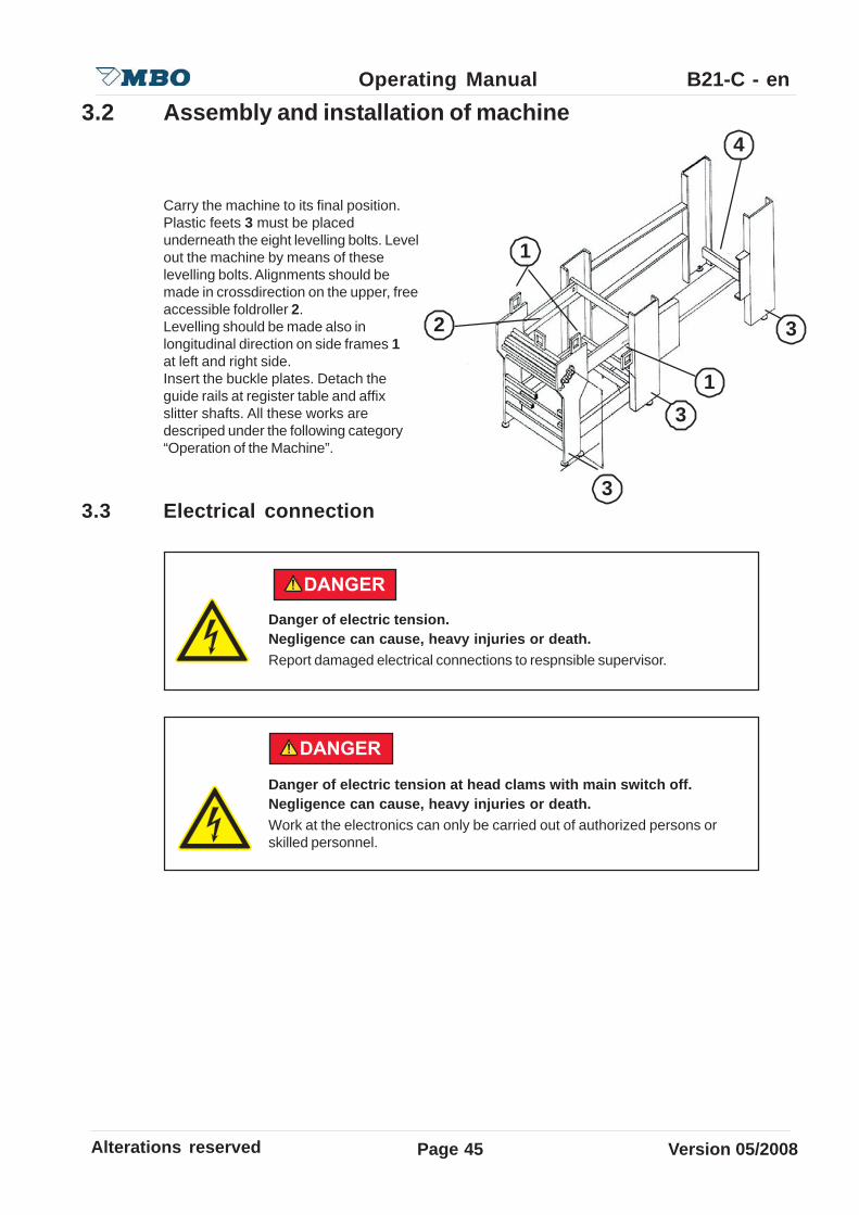
3.3 Electrical connection
Danger of electric tension.Negligence can cause, heavy injuries or death.Report damaged electrical connections to respnsible supervisor.
Danger of electric tension at head clams with main switch off.Negligence can cause, heavy injuries or death.Work at the electronics can only be carried out of authorized persons orskilled personnel.
3.2 Assembly and installation of machine
Carry the machine to its final position.Plastic feets 3 must be placedunderneath the eight levelling bolts. Levelout the machine by means of theselevelling bolts. Alignments should bemade in crossdirection on the upper, freeaccessible foldroller 2.Levelling should be made also inlongitudinal direction on side frames 1at left and right side.Insert the buckle plates. Detach theguide rails at register table and affixslitter shafts. All these works aredescriped under the following category“Operation of the Machine”.
1
2
3
4
1
3
3
Page46Alterations reserved Version 05/2008
Operating Manual B21-C - en
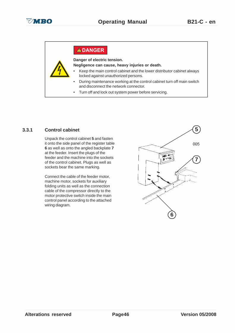
3.3.1 Control cabinet
Unpack the control cabinet 5 and fastenit onto the side panel of the register table6 as well as onto the angled backplate 7at the feeder. Insert the plugs of thefeeder and the machine into the socketsof the control cabinet. Plugs as well assockets bear the same marking.
Connect the cable of the feeder motor,machine motor, sockets for auxiliaryfolding units as well as the connectioncable of the compressor directly to themotor protective switch inside the maincontrol panel according to the attachedwiring diagram.
Danger of electric tension.Negligence can cause, heavy injuries or death.• Keep the main control cabinet and the lower distributor cabinet always
locked against unauthorized persons.• During maintenance working at the control cabinet turn off main switch
and disconnect the network connector.• Turn off and lock out system power before servicing.
6
7
5

Alterations reserved Version 05/2008
Operating Manual B21-C - en
Page 47
3.3.2 Main current connection
Danger, the printed circuit board (p.c.b.) of the stream delivery isprovided with 220 voltages!Negligence can cause heavy injuries or death.If you are working on the opened cabinet of the delivery make sure that nopower is supplied or do not touch this p.c.b!
Make sure that power supply and frequency correspond with the data ofyour machine! These data should be checked with the label on the side ofthe control cabinet.
3.3.3 Stream delivery
Consider Clockwise rotating field! After wiring has been completed theterminals must be protected with cover plates provided .
After connections have been completed check the rotating field of motorsas described under item 3.3.1. However, if one of these motors shouldhave the wrong rotating field, change the connection of the individual motorat the terminal. Turn OFF the machine immediately, if direction of pile platedoes not correspond with switch position 1.10 at main control panel.Otherwise the limit switch control will not function properly and switchOFF! This may cause serious personal injuries or extensive damage to thefeeder !
Insert the cable in the base of the control cabinet and connect it with the main terminals providedaccording to the attached wiring diagram.

Page48Alterations reserved Version 05/2008
Operating Manual B21-C - en4.0 Maintenance
This part of the Operating Manual is directed to the competent service personnel and internalauthorized personnel.
Danger through maintenance tool.Negligence can cause heavy personal injuries or extensive damages.• Use only tools in good working condition.• Pay attention that after adjustment or maintenance working at the
machine, all tools are removed.
Danger of running machine parts.Negligence can cause heavy personal injuries or extensive damages.• Safety switches at the protection and noise hoods can not be
manipulated or modified.• Never carry out foldroller settings while machine is still running.• Even manual foldroller setting by the handwheel.
Danger of running machine parts during the installation work.Negligence can cause heavy personal injuries or extensive damages.• Allow service and cleaning works only to be carryed.• Turn off the machine during maintenance and restoration work by the
main switch.• Neutralize the electrical cabinet against unintentional switch on.• Check before turning on, that no further person is at the machine.
Danger of slitter shafts.Negligence can cause cut injuries.• During maintenance work at the slitter shafts, the use of
protection gloves and safteyshoes is required.• Do not hold the slitter shafts by the tool but always at the
shaft.

Alterations reserved Version 05/2008
Operating Manual B21-C - en
Page 49
4.1 Tensioning or exchange of belts/tapes
The tension of drive belts, and especially for foldrollers and slitter shaft drives should be checkedperiodically, i.e. monthly. The drive belts must be tensioned to such an extent that the foldrollerscannot manually be held if the machine is turned by handwheel.
Danger before running belt-drive.Negligence can cause, bruise emerges at the hands.This work should be carried out by one person only !
4.1.1 Upper feeder transport tape
For an undisturbed transport, the uppertransport tape (1) must be strainedtightly. Re-strain the tape if required:Turn both screws (2).The adjustment must be undertaken onboth sides equal.The tape will be led by disks (3)
4.1.2 Lower feeder transport tape
For an undisturbed transport, the uppertransport tape (1) must be strainedtightly. Re-strain the tape if required:Turn both screws (2). The adjustmentmust be undertaken on both sides equal.The tape will be led by disks (3).
3
1
2
4
5
6
2

Page50Alterations reserved Version 05/2008
Operating Manual B21-C - en
4.1.4 Alignment tape at register table
Loosen screw 5 and 6 release tension oftape. For threading/rethreading unhingethe lattice-type alignment table at pos. 3.Loosen screw 2, push back the rod 1 indirection of drive side, remove tape fromthe rollers and rethread at pos. 4. Installnew tape in the opposite sequence andtension it throughscrew 6.Adjustment for centre running of tapeoccurs through screw 8.For this purpose loosen the screw 9(screw 8 and 9 are located at the internalside) and fasten it again after completion.Thereafter, check again and, ifnecessary, make necessary corrections.
4.1.3 Feeder chain
Test the feeder chain occasionally for itstension and re-strain if necessary.Strain the drive chain (2) with the chaintensioner (1).
1 2
1 3
4 65
2
8 94
Alterations reserved Version 05/2008
Operating Manual B21-C - en
Page 51
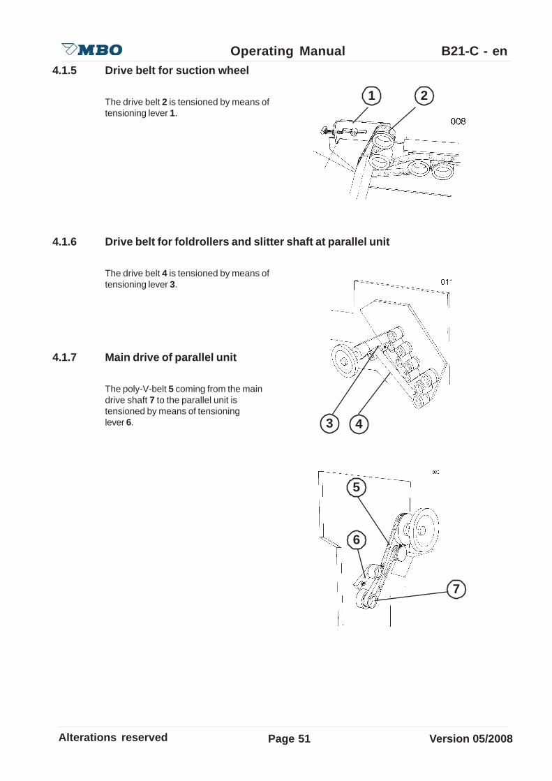
4.1.5 Drive belt for suction wheel
The drive belt 2 is tensioned by means oftensioning lever 1.
4.1.6 Drive belt for foldrollers and slitter shaft at parallel unit
The drive belt 4 is tensioned by means oftensioning lever 3.
4.1.7 Main drive of parallel unit
The poly-V-belt 5 coming from the maindrive shaft 7 to the parallel unit istensioned by means of tensioninglever 6.
1 2
3 4
7
6
5

Page52Alterations reserved Version 05/2008
Operating Manual B21-C - en
4.1.8 Drive belt for foldrollers at parallel unit and slitter shafts at subsequent unit
See item 4.1.3 page 49.
4.1.9 Drive belt at register table of following folding unit
Danger, overstretching of the drive belt.Negligence can cause material damage.Let the folding unit run by turning the hand wheel. At the same time thecross rollers must be easy to stop with the other hand.
The drive belt 6 should be tensioned bymeans of tape tensioner 5.
Danger befor running belt drive.Danger of injuries to fingers.This work should be carried out by one person only !
6
5
Alterations reserved Version 05/2008
Operating Manual B21-C - en
Page 53
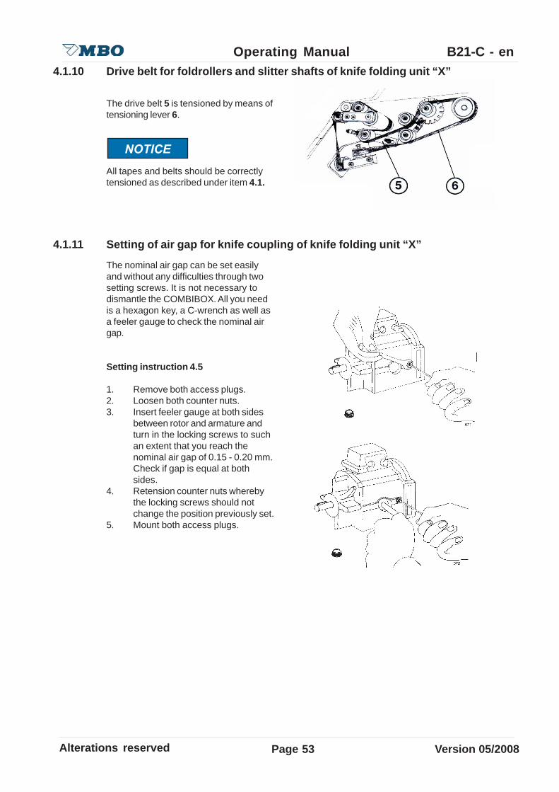
4.1.10 Drive belt for foldrollers and slitter shafts of knife folding unit “X”
The drive belt 5 is tensioned by means oftensioning lever 6.
All tapes and belts should be correctlytensioned as described under item 4.1.
4.1.11 Setting of air gap for knife coupling of knife folding unit “X”
The nominal air gap can be set easilyand without any difficulties through twosetting screws. It is not necessary todismantle the COMBIBOX. All you needis a hexagon key, a C-wrench as well asa feeler gauge to check the nominal airgap.
Setting instruction 4.5
1. Remove both access plugs.2. Loosen both counter nuts.3. Insert feeler gauge at both sides
between rotor and armature andturn in the locking screws to suchan extent that you reach thenominal air gap of 0.15 - 0.20 mm.Check if gap is equal at bothsides.
4. Retension counter nuts wherebythe locking screws should notchange the position previously set.
5. Mount both access plugs.

Page54Alterations reserved Version 05/2008
Operating Manual B21-C - en4.2 Lubrication / Cleaning
Generally, the machine should be cleaned after each job, particularly moveable parts which havebeen changed due to change of sheet size, because heavy dust may cause reduction of function.
4.2.1 Main machine including register table
Clean dust off guide shaft 2 for change ofsheet size at register table as well asdrive shaft 1 and supply a slight touch ofoil.Safety handwheels should alsooccasionally be relubricated at nipples 3.
4.2.2 Continuous feeder R
Clean drive chain 4 grease slightly.
4.2.3 Guides of pressure bars / Bearings of foldrollers
Supply a slight touch of oil to allpressure bars of foldrollers and slittershafts in all folding units 6 as well asbetween the machine panel and bearinglevers 5, monthly (also parallel unit).
5
1 2
3
4
6
Alterations reserved Version 05/2008
Operating Manual B21-C - en
Page 55
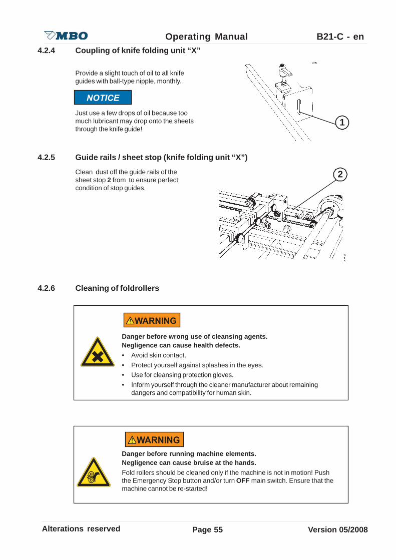
4.2.4 Coupling of knife folding unit “X”
Provide a slight touch of oil to all knifeguides with ball-type nipple, monthly.
Just use a few drops of oil because toomuch lubricant may drop onto the sheetsthrough the knife guide!
4.2.5 Guide rails / sheet stop (knife folding unit “X”)
Clean dust off the guide rails of thesheet stop 2 from to ensure perfectcondition of stop guides.
4.2.6 Cleaning of foldrollers
Danger before running machine elements.Negligence can cause bruise at the hands.Fold rollers should be cleaned only if the machine is not in motion! Pushthe Emergency Stop button and/or turn OFF main switch. Ensure that themachine cannot be re-started!
Danger before wrong use of cleansing agents.Negligence can cause health defects.• Avoid skin contact.• Protect yourself against splashes in the eyes.• Use for cleansing protection gloves.• Inform yourself through the cleaner manufacturer about remaining
dangers and compatibility for human skin.
2
1
Page56Alterations reserved Version 05/2008
Operating Manual B21-C - en
Depending on the extent of ink build-up, the foldrollers must be cleaned from time to time. Theaffect of printing powder or ink build-up on the foldrollers may decrease the quality of the folding.The rollers must be cleaned with a cleansing agent suitable for the synthetic material. Pleasecontact your machine supplier. Improper cleaner may cause decomposure or swelling of thefoldroller coating.MBO - the manufacturer of this folding machine recommends a cleaning material for the foldrollersmade by VARN, bearing the no. VARN -Wash VM 111 or VWM. Our recommendation is on a labelnear the foldrollers.The VARN company is a worldwide supplier for the printing industry. Therefore, it cannot beexcluded that in certain other countries different indications are used. Please take the individualorder no. from the technical data sheets of VARN.
Danger before used cleaning rags.Negligence can cause health defects.• Note the fire dangers through the flammability of the cleaner.• Detoxifythe cleaning rags.• Inform yourself at the cleaner manufacturer about remaining dangers as
well as over the correct disposal.
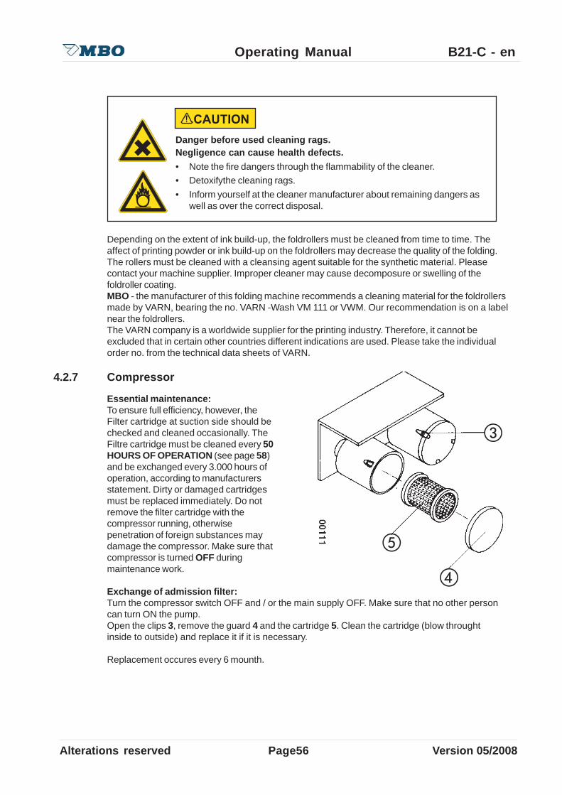
4.2.7 Compressor
Essential maintenance:To ensure full efficiency, however, theFilter cartridge at suction side should bechecked and cleaned occasionally. TheFiltre cartridge must be cleaned every 50HOURS OF OPERATION (see page 58)and be exchanged every 3.000 hours ofoperation, according to manufacturersstatement. Dirty or damaged cartridgesmust be replaced immediately. Do notremove the filter cartridge with thecompressor running, otherwisepenetration of foreign substances maydamage the compressor. Make sure thatcompressor is turned OFF duringmaintenance work.
Exchange of admission filter:Turn the compressor switch OFF and / or the main supply OFF. Make sure that no other personcan turn ON the pump.Open the clips 3, remove the guard 4 and the cartridge 5. Clean the cartridge (blow throughtinside to outside) and replace it if it is necessary.
Replacement occures every 6 mounth.
Alterations reserved Version 05/2008
Operating Manual B21-C - en
Page 57
5.0 Operation of the machineIn addition to the numbers the operating sequences to operate the machine are marked with B.
Danger of running machines part.Negligence can cause, heavy injuries or death.• Keep hairs always together bandage and protected.• Take by operation and maintenance working at the machine your
jewellery off.• Carry during operation or maintenance on the machine only adjoining
garment.
Danger of sound pressure.Negligence can cause, ear damage can emerge.Use an ear protection for work at the folding machine.
Danger of running machines part.Negligence can cause, heavy injuries or death.In sudden stop of the machine, review before turning on:• That no further person is at the machine.• That the machine is in a flawless condition.
Danger of running machine parts.Negligence can cause heavy personal injuries or extensive damages.• Never carry out foldroller settings while machine is still running.• Even manual foldroller setting by the handwheel.

Page58Alterations reserved Version 05/2008
Operating Manual B21-C - enB 1.0 Main control panel
For more information see separated operating manual “MS - Control”.
1.1 MAIN SWITCH1.2 Turn ON/OFF switch for compressor1.3 EMERGENCY-STOP button1.4 Red button for machine STOP1.5 Black button for machine START1.6 White button for SHEET INFEED1.7 White button for SINGLE SHEET INFEED1.8 Green indicator light for MACHINE RELEASE1.9 8- digit display1.10 Button suction length1.11 Button suction gap1.12 Button with double function 7 / +1.13 Button with multliple function 4/ speed up delievery/ Kicker/ marking device1.14 Button with double function 8 / -1.15 Button with double function 9 / speed indication1.16 Button with double function 5 / interruption suction wheel1.17 Button with double function 6 / current productions speed / hrs1.18 Button with double function 3 / total counter at infeed1.19 Button with double function 2 / total counter at exit1.20 Button Clear (delete)1.21 Button 01.22 Button 11.23 Button Enter (confirm)1.24 Button Batch preselection1.25 Button Code1.26 Diagnosis LED photocell at exit B 43 (Option)1.27 Diagnosis LED photocell at suction wheel B 21.28 Diagnosis LED slot initiator B 11.29 Potentiometer for electronical speed regulation
12
1 2 3 4 5 6 7
1819
20
21
23
17
16151413
27
24
26
29
109
8
28 11
2225
Alterations reserved Version 05/2008
Operating Manual B21-C - en
Page 59
B 2.0 Continuous feeder C
2.1 Generally settings
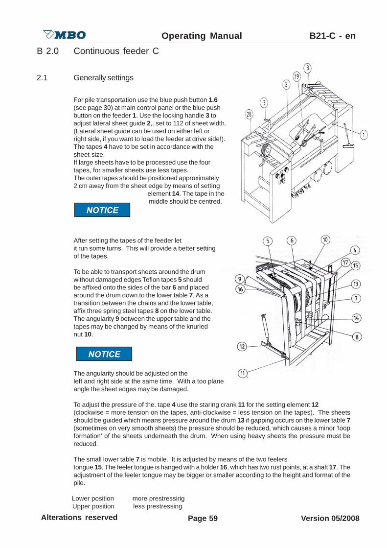
For pile transportation use the blue push button 1.6(see page 30) at main control panel or the blue pushbutton on the feeder 1. Use the locking handle 3 toadjust lateral sheet guide 2,. set to 112 of sheet width.(Lateral sheet guide can be used on either left orright side, if you want to load the feeder at drive side!).The tapes 4 have to be set in accordance with thesheet size.If large sheets have to be processed use the fourtapes, for smaller sheets use less tapes.The outer tapes should be positioned approximately2 cm away from the sheet edge by means of setting
element 14. The tape in the middle should be centred.
After setting the tapes of the feeder letit run some turns. This will provide a better settingof the tapes.
To be able to transport sheets around the drumwithout damaged edges Teflon tapes 5 shouldbe affixed onto the sides of the bar 6 and placedaround the drum down to the lower table 7. As atransition between the chains and the lower table,affix three spring steel tapes 8 on the lower table.The angularity 9 between the upper table and thetapes may be changed by means of the knurlednut 10.
The angularity should be adjusted on theleft and right side at the same time. With a too planeangle the sheet edges may be damaged.
To adjust the pressure of the. tape 4 use the staring crank 11 for the setting element 12(clockwise = more tension on the tapes, anti-clockwise = less tension on the tapes). The sheetsshould be guided which means pressure around the drum 13 if gapping occurs on the lower table 7(sometimes on very smooth sheets) the pressure should be reduced, which causes a minor ‘loopformation’ of the sheets underneath the drum. When using heavy sheets the pressure must bereduced.
The small lower table 7 is mobile. It is adjusted by means of the two feelerstongue 15. The feeler tongue is hanged with a holder 16, which has two rust points, at a shaft 17. Theadjustment of the feeler tongue may be bigger or smaller according to the height and format of thepile.
Lower position more prestressirig Upper position less prestressing

Page60Alterations reserved Version 05/2008
Operating Manual B21-C - en
A slightly tension should be adjusted.
Load and fan out the sheets on the uppertable; the entire table may be loaded and streamedwith wooden paddle 18 . By detaching stainlesssteel rods 19 you achieve and additional extensionof the upper table.
The sheets which are transported on thelower table are controlled through a feelertongue 20 which is placed underneath thesuction wheel. In order to obtain an exactposition of the sheet it is necessary to installa guide plate 21 at drive side and the guidepin 22 at operator side.
Both guide elements shouldn’tbe too tight to the sheets or otherwise it maylead to a jam-up.
At the end of the shingled sheets soft rubberrollers 23 as well as a brush 24 should be placedon top of the first 2-5 sheets to achieve asafe sheet separation. The rollers 23 maybe adjusted therefore loosen the adjustmentring 25 with the knurled screw on the desiredsheet length. The sheet length may be read-offon a scale 26.
2.2 Air support
Air pressure and vacuum are supplied by acompressor, which can be turn ON/OFFthrough switch 1.2 (see page 30) at maincontrol panel. Carefully read the technicaldata sheet or maintenance data which areattached to this Operating Manual.
It is extremely important to clean both filter cartridges 36 and 37 (see item 4.2 page 29)!
Alterations reserved Version 05/2008
Operating Manual B21-C - en
Page 61
2.3 Transportation system - ventilation
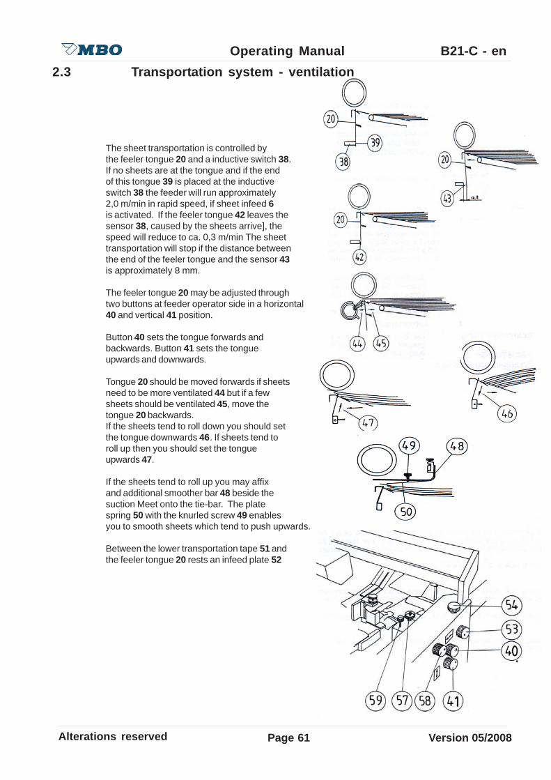
The sheet transportation is controlled bythe feeler tongue 20 and a inductive switch 38.If no sheets are at the tongue and if the endof this tongue 39 is placed at the inductiveswitch 38 the feeder will run approximately2,0 m/min in rapid speed, if sheet infeed 6is activated. If the feeler tongue 42 leaves thesensor 38, caused by the sheets arrive], thespeed will reduce to ca. 0,3 m/min The sheettransportation will stop if the distance betweenthe end of the feeler tongue and the sensor 43is approximately 8 mm.
The feeler tongue 20 may be adjusted throughtwo buttons at feeder operator side in a horizontal40 and vertical 41 position.
Button 40 sets the tongue forwards andbackwards. Button 41 sets the tongueupwards and downwards.
Tongue 20 should be moved forwards if sheetsneed to be more ventilated 44 but if a fewsheets should be ventilated 45, move thetongue 20 backwards.If the sheets tend to roll down you should setthe tongue downwards 46. If sheets tend toroll up then you should set the tongueupwards 47.
If the sheets tend to roll up you may affixand additional smoother bar 48 beside thesuction Meet onto the tie-bar. The platespring 50 with the knurled screw 49 enablesyou to smooth sheets which tend to push upwards.
Between the lower transportation tape 51 andthe feeler tongue 20 rests an infeed plate 52

Page62Alterations reserved Version 05/2008
Operating Manual B21-C - en
Between the lower transportation tape 51 andthe feeler tongue 20 rests an infeed plate 52which may be adjusted through a knurledgrip 53 after loosen the knurled screw 54 upwardsand downwards.
Set the plate upwards if sheets tend to roll down.Set the plate downwards if sheets tend to roll up.
The air tube 27 is located underneath thesuction wheel. It contains air dischargeholes 55 alongits Mole length. These discharge holes maybe opened or closed through slide clips 56.These clips should be opened in accordanceto the sheet width, the remaining clipsshould be closed. In order to achieve moreair blast at the side blower it is advisable toopen every send clip only. However, theclips in the centre of the air tube underneaththe suction wheel should be opened continuously.
The air tube is height adjustable through knurled nut 57. On the knurled grip 58 the air tube may also be turned after loosen
the knurled screw 59.
20
Alterations reserved Version 05/2008
Operating Manual B21-C - en
Page 63
30 32 3334
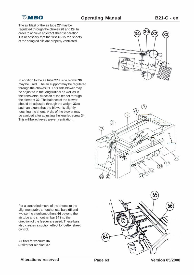
The air blast of the air tube 27 may beregulated through the chokes 28 and 29. Inorder to achieve an exact sheet separationit is necessary that the first 10-15 top sheetsof the shingled pile are properly ventilated.
In addition to the air tube 27 a side blower 30may be used. The air support may be regulatedthrough the chokes 31. This side blower maybe adjusted in the longitudinal as well as inthe transversal direction of the feeder throughthe element 32. The balance of the blowershould be adjusted through the weight 33 tosuch an extent that the blower is slightlytouching the sheet. A dip of the blower maybe avoided after adjusting the knurled screw 34.This will be achieved a even ventilation.
For a controlled move of the sheets to thealignment table smoother use bars 65 andtwo spring steel smoothers 66 beyond theair tube and smoother bar 64 into thedirection of the feeder are used. These barsalso creates a suction effect for better sheetcontrol.
Air filter for vacuum 36 Air filter for air blast 37
2720

Page64Alterations reserved Version 05/2008
Operating Manual B21-C - en2.4 Suction wheel
The suction wheel 1 which transports thesheets onto the alignment table enablesyou to change the point of suction .Generally, the point of suction should beat the lowest position of the suctionwheel, for which the adjustment lever 2must be in a vertical position. However,should the suction point be movedforward (if sheets are curled at front)move the lever into the upwards direction.Should, however, the point of suction bemoved to the rear (if sheets are curledup) move the lever into the downwardsdirection. When processing sensitivepapers and double sheets are supportedfrequently you may decrease the vacuumat suction wheel.Near the suction wheel you can find ahandle 3. The handle 3 has got a screw 4and two air holes 5.The screw 4 hasbeen completely screwed-in bymanufacturer and the holes are closed.Partial unscrewing of this screw willcause the opening of one or both ofthese holes. You can open the air hole 7by turning the disc 6. The opening of theair holes will than cause a decrease ofvacuum at suction wheel.
With all holes closed maximum quantity of vacuumWith some holes open medium quantity of vacuumWith all holes open minimum quantity of vacuum
7
1
3 2
4
6
5
Alterations reserved Version 05/2008
Operating Manual B21-C - en
Page 65
2
1
3
4
2.5 Vacu-Infeed (Option)
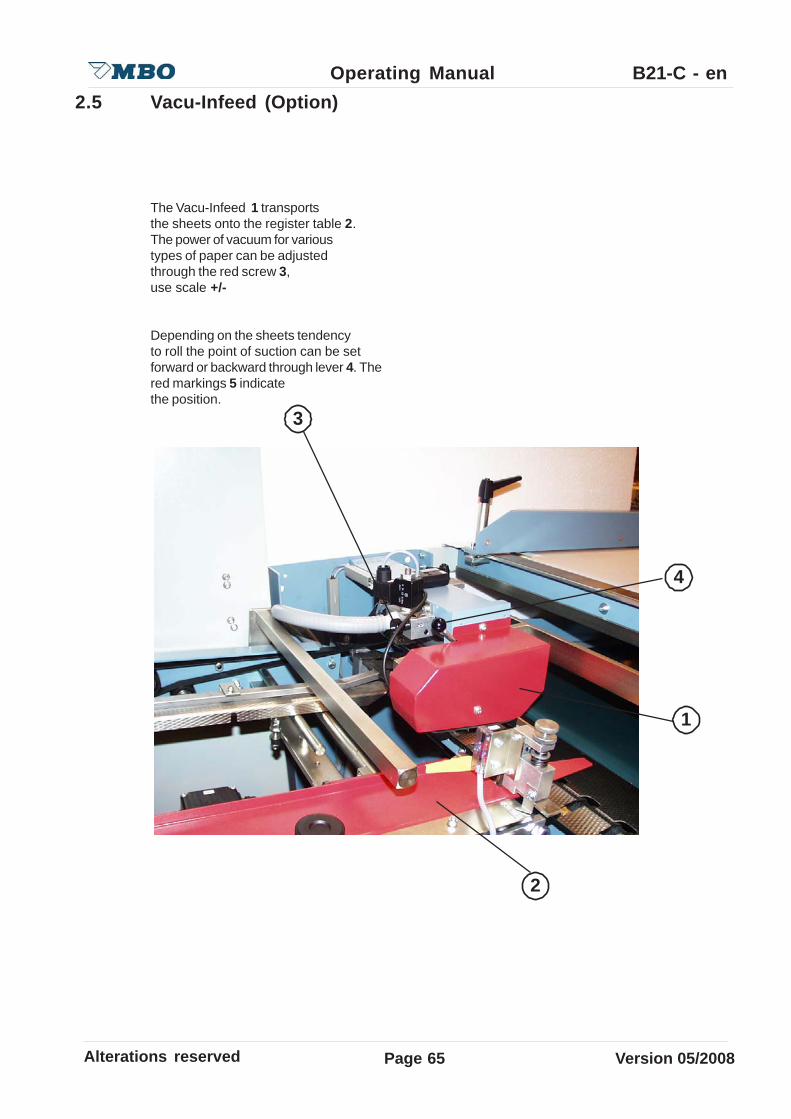
The Vacu-Infeed 1 transportsthe sheets onto the register table 2.The power of vacuum for varioustypes of paper can be adjustedthrough the red screw 3,use scale +/-
Depending on the sheets tendencyto roll the point of suction can be setforward or backward through lever 4. Thered markings 5 indicatethe position.
Page66Alterations reserved Version 05/2008
Operating Manual B21-C - enB 3.0 Register table with ball rail, double sheet control, sheet
infeed control
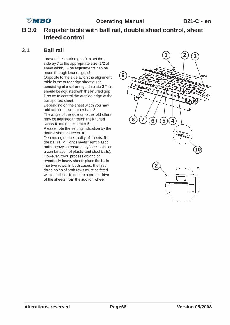
3.1 Ball railLoosen the knurled grip 9 to set thesidelay 7 to the appropriate size (1/2 ofsheet width). Fine adjustments can bemade through knurled grip 8.Opposite to the sidelay on the alignmenttable is the outer edge sheet guideconsisting of a rail and guide plate 2 Thisshould be adjusted with the knurled grip1 so as to control the outside edge of thetransported sheet.Depending on the sheet width you mayadd additional smoother bars 3.The angle of the sidelay to the foldrollersmay be adjusted through the knurledscrew 6 and the excenter 5.Please note the setting indication by thedouble sheet detector 10.Depending on the quality of sheets, fillthe ball rail 4 (light sheets=light/plasticballs, heavy sheets=heavy/steel balls, ora combination of plastic and steel balls).However, if you process oblong oreventually heavy sheets place the ballsinto two rows. In both cases, the firstthree holes of both rows must be fittedwith steel balls to ensure a proper driveof the sheets from the suction wheel.
1 32
4678 5
10
9
2
Alterations reserved Version 05/2008
Operating Manual B21-C - en
Page 67
3.1.1 Vacu-Alignment (Option)
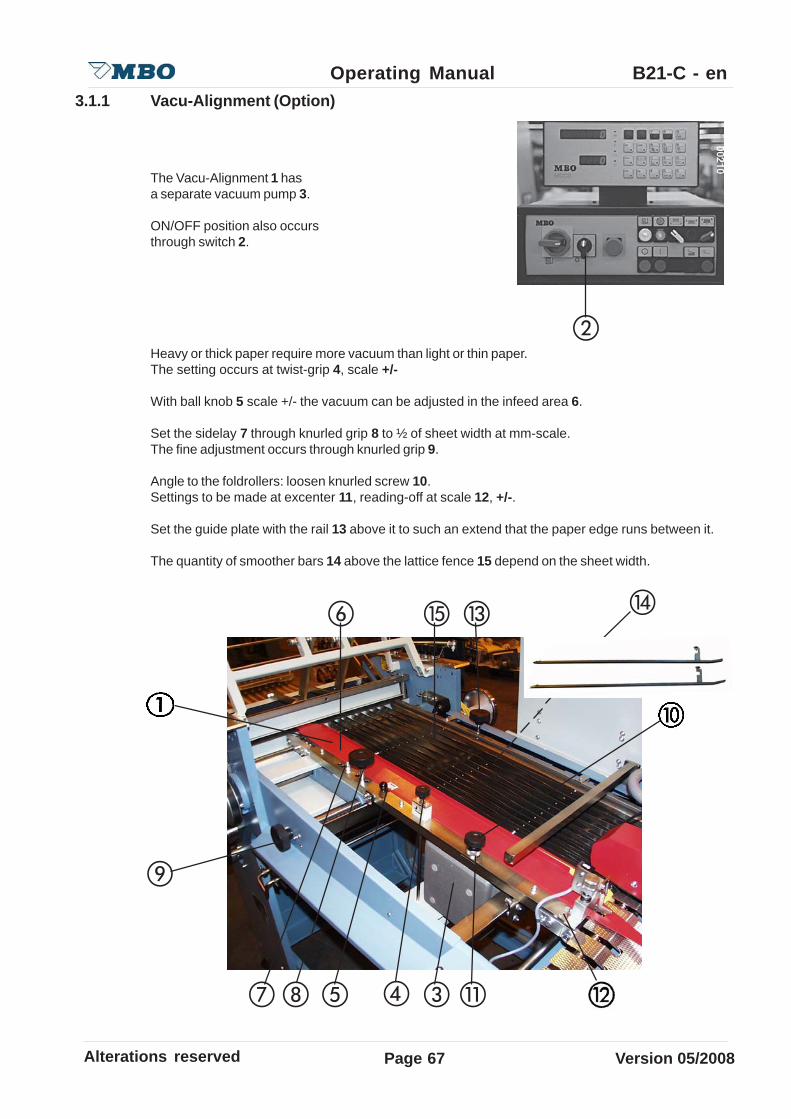
The Vacu-Alignment 1 hasa separate vacuum pump 3.
ON/OFF position also occursthrough switch 2.
Heavy or thick paper require more vacuum than light or thin paper.The setting occurs at twist-grip 4, scale +/-
With ball knob 5 scale +/- the vacuum can be adjusted in the infeed area 6.
Set the sidelay 7 through knurled grip 8 to ½ of sheet width at mm-scale.The fine adjustment occurs through knurled grip 9.
Angle to the foldrollers: loosen knurled screw 10.Settings to be made at excenter 11, reading-off at scale 12, +/-.
Set the guide plate with the rail 13 above it to such an extend that the paper edge runs between it.
The quantity of smoother bars 14 above the lattice fence 15 depend on the sheet width.
Page68Alterations reserved Version 05/2008
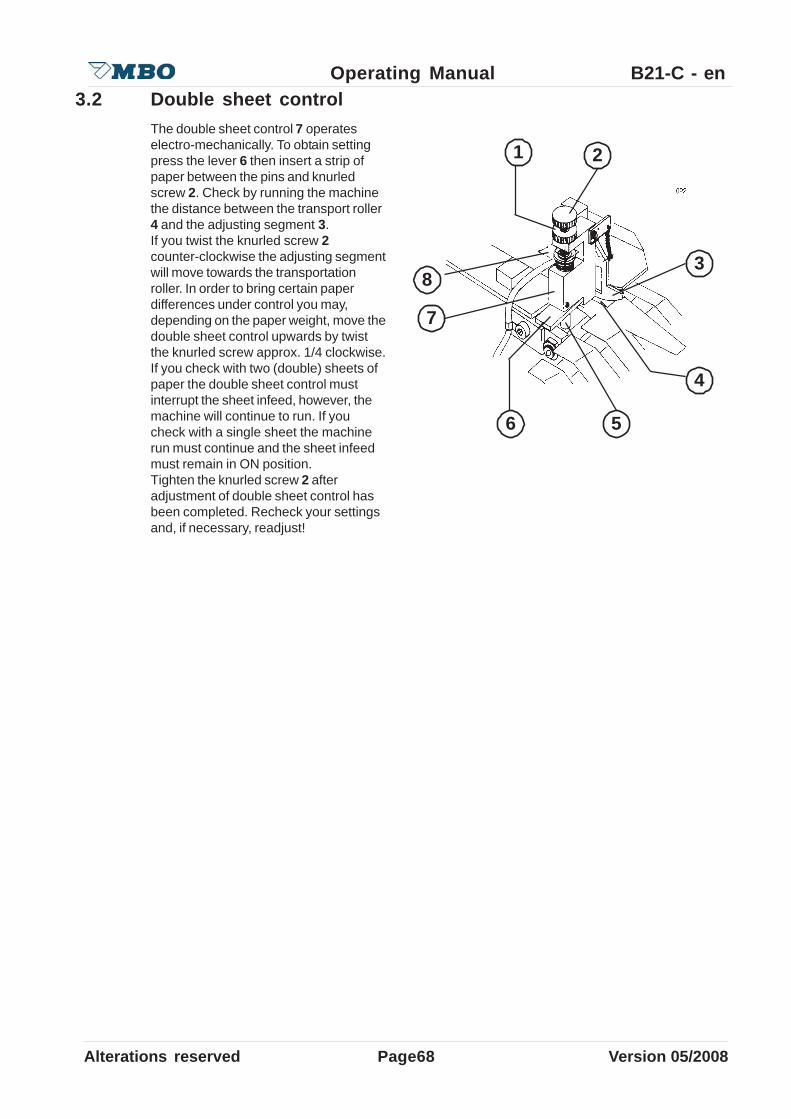
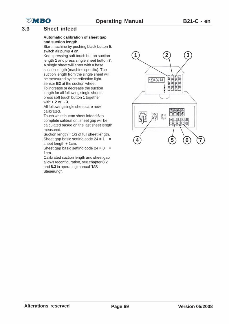
Operating Manual B21-C - en3.2 Double sheet control
The double sheet control 7 operateselectro-mechanically. To obtain settingpress the lever 6 then insert a strip ofpaper between the pins and knurledscrew 2. Check by running the machinethe distance between the transport roller4 and the adjusting segment 3.If you twist the knurled screw 2counter-clockwise the adjusting segmentwill move towards the transportationroller. In order to bring certain paperdifferences under control you may,depending on the paper weight, move thedouble sheet control upwards by twistthe knurled screw approx. 1/4 clockwise.If you check with two (double) sheets ofpaper the double sheet control mustinterrupt the sheet infeed, however, themachine will continue to run. If youcheck with a single sheet the machinerun must continue and the sheet infeedmust remain in ON position.Tighten the knurled screw 2 afteradjustment of double sheet control hasbeen completed. Recheck your settingsand, if necessary, readjust!
1
3
2
4
6
7
8
5
Alterations reserved Version 05/2008
Operating Manual B21-C - en
Page 69
3.3 Sheet infeedAutomatic calibration of sheet gapand suction lengthStart machine by pushing black button 5,switch air pump 4 on.Keep pressing soft touch button suctionlength 1 and press single sheet button 7.A single sheet will enter with a basesuction length (machine specific). Thesuction length from the single sheet willbe measured by the reflection lightsensor B2 at the suction wheel.To increase or decrease the suctionlength for all following single sheetspress soft touch button 1 togetherwith + 2 or - 3.All following single sheets are newcalibrated.Touch white button sheet infeed 6 tocomplete calibration, sheet gap will becalculated based on the last sheet lengthmeusured.Suction length = 1/3 of full sheet length.Sheet gap basic setting code 24 = 1 =sheet length + 1cm.Sheet gap basic setting code 24 = 0 =1cm.Calibrated suction length and sheet gapallows reconfiguration, see chapter 8.2and 8.3 in operating manual “MS-Steuerung”.
1 2 3
4 5 6 7
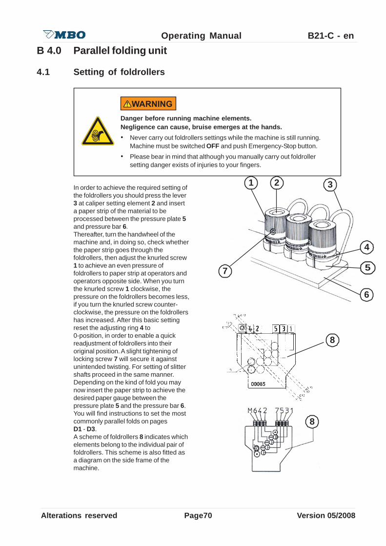
Page70Alterations reserved Version 05/2008
Operating Manual B21-C - enB 4.0 Parallel folding unit
4.1 Setting of foldrollers
In order to achieve the required setting ofthe foldrollers you should press the lever3 at caliper setting element 2 and inserta paper strip of the material to beprocessed between the pressure plate 5and pressure bar 6.Thereafter, turn the handwheel of themachine and, in doing so, check whetherthe paper strip goes through thefoldrollers, then adjust the knurled screw1 to achieve an even pressure offoldrollers to paper strip at operators andoperators opposite side. When you turnthe knurled screw 1 clockwise, thepressure on the foldrollers becomes less,if you turn the knurled screw counter-clockwise, the pressure on the foldrollershas increased. After this basic settingreset the adjusting ring 4 to0-position, in order to enable a quickreadjustment of foldrollers into theiroriginal position. A slight tightening oflocking screw 7 will secure it againstunintended twisting. For setting of slittershafts proceed in the same manner.Depending on the kind of fold you maynow insert the paper strip to achieve thedesired paper gauge between thepressure plate 5 and the pressure bar 6.You will find instructions to set the mostcommonly parallel folds on pagesD1 - D3.A scheme of foldrollers 8 indicates whichelements belong to the individual pair offoldrollers. This scheme is also fitted asa diagram on the side frame of themachine.
Danger before running machine elements.Negligence can cause, bruise emerges at the hands.• Never carry out foldrollers settings while the machine is still running.
Machine must be switched OFF and push Emergency-Stop button.• Please bear in mind that although you manually carry out foldroller
setting danger exists of injuries to your fingers.
1 2 3
4
5
6
8
8
7
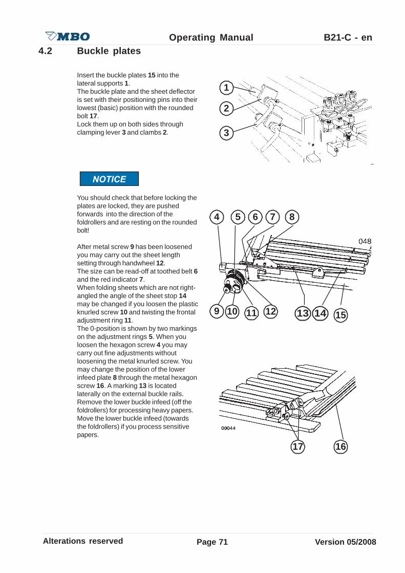
Alterations reserved Version 05/2008
Operating Manual B21-C - en
Page 71
4.2 Buckle plates
Insert the buckle plates 15 into thelateral supports 1.The buckle plate and the sheet deflectoris set with their positioning pins into theirlowest (basic) position with the roundedbolt 17.Lock them up on both sides throughclamping lever 3 and clambs 2.
You should check that before locking theplates are locked, they are pushedforwards into the direction of thefoldrollers and are resting on the roundedbolt!
After metal screw 9 has been loosenedyou may carry out the sheet lengthsetting through handwheel 12.The size can be read-off at toothed belt 6and the red indicator 7.When folding sheets which are not right-angled the angle of the sheet stop 14may be changed if you loosen the plasticknurled screw 10 and twisting the frontaladjustment ring 11.The 0-position is shown by two markingson the adjustment rings 5. When youloosen the hexagon screw 4 you maycarry out fine adjustments withoutloosening the metal knurled screw. Youmay change the position of the lowerinfeed plate 8 through the metal hexagonscrew 16. A marking 13 is locatedlaterally on the external buckle rails.Remove the lower buckle infeed (off thefoldrollers) for processing heavy papers.Move the lower buckle infeed (towardsthe foldrollers) if you process sensitivepapers.
1
3
2
4 6 7 85
9 12
17 16
15141310 11

Page72Alterations reserved Version 05/2008
Operating Manual B21-C - en
When you change the setting screw 1you may achieve a larger or smallerbuckle space 2 between the lower bucklelip and foldroller:
small folding space for porous papers = turn screw to inner directionlarge folding space for heavy papers = turn screw to outer direction or take
buckle plate back
This setting should be made only in exceptional cases! It is absolutely imperative to reset to basicsetting. If necessary, contact manufacturer or supplier for basic measurements.
4.3 DeflectorsThe buckle plates which are not used forthe individual type of fold are replaced bydeflectors 3.In this case pull out the buckle platesand dislocate the installed deflectors.Heavy (multiple) folded sheets mayrequire an increase of the deflector area,for which purpose you should slightlypullout the buckle plates.If the perforating or scoring line 4 are notsquare to the folding line 5 pull out thedeflector or buckle plate at one side tocorrect perforating position.
If the buckle plate has been set too deep the plate will damagethe foldrollers.
1
3
2
4 5
3

Alterations reserved Version 05/2008
Operating Manual B21-C - en
Page 73
Funktion ”Deflector”:Turn the sheet stop 1 with theadjustment ring 3 to lower position untilthe angle 4 stops.
For perforating,cutting, etc., pull thedeflector at one side.See 4.3 too.
4.4 Combi buckle plates FTK (Option)
In this kind of buckle plate, the sheetstop can be used as a defector.Buckle plate/Deflector must not to beremoved.
Sheet stop 1 is adeflector 2 too.
Funktion „Buckle plate“: See 4.2
-2 may not have contact with the fold rollers!- Do not make any alteration of the position from the screws 5,6,7 and 8.

Page74Alterations reserved Version 05/2008
Operating Manual B21-C - enB 5.0 Slitter shafts
Both slitter shafts 1 which are fitted aftereach folding unit may easily be mountedand removed by plug bearings 3 enablinginsertion of tools for perforation, scoringor cutting. For removal of the slittershafts loosen the internal hexagon screw2 which locks the plug bearing. Pull theplug bearing out of the slitter shaft whileholding the slitter shaft with your otherhand. Reinstallation occurs in theopposite sequence. However, push theplug bearing against the slitter shaft - toequalize an axial play - while you arelocking the plug bearing with the internalhexagon screw.
5.1 PerforatingTo avoid creasing you perforate crossfold as well as for tear or punch perforation.To use perforating or cutting knives, a knife shaft 9 as well as a counter knife (lower part) 11 isrequired. When loosening the nut 7 you may fit a knife 8 into the holder.Some knives are split 12, which enables you to install them without removing the shaft.For proper installation the knife 8 should be adjacent to the ground side of counter knife 10Make sure that during the installation of the shaft that the nut 7 is opposite to the direction of theshafts rotation 8. This guarantees that the nut does not become loose during rotation. The locknut may also be retightened with a C-wrench.Perforating knives with slanted teeth must be installed in such a manner that they enter with theobtuse angle first into the sheet. In doing so you may avoid jam-up of sheets between perforatingknife and stripper 4.Depending on the sheet size you may use additional transport rollers 5. Carefully read theattached knife list TM 35/2 which indicates the knives you should use when processing differentkind of papers and/or making different types of folds.
1
2
3
5 6 7 98
4
5
5
12
10 115
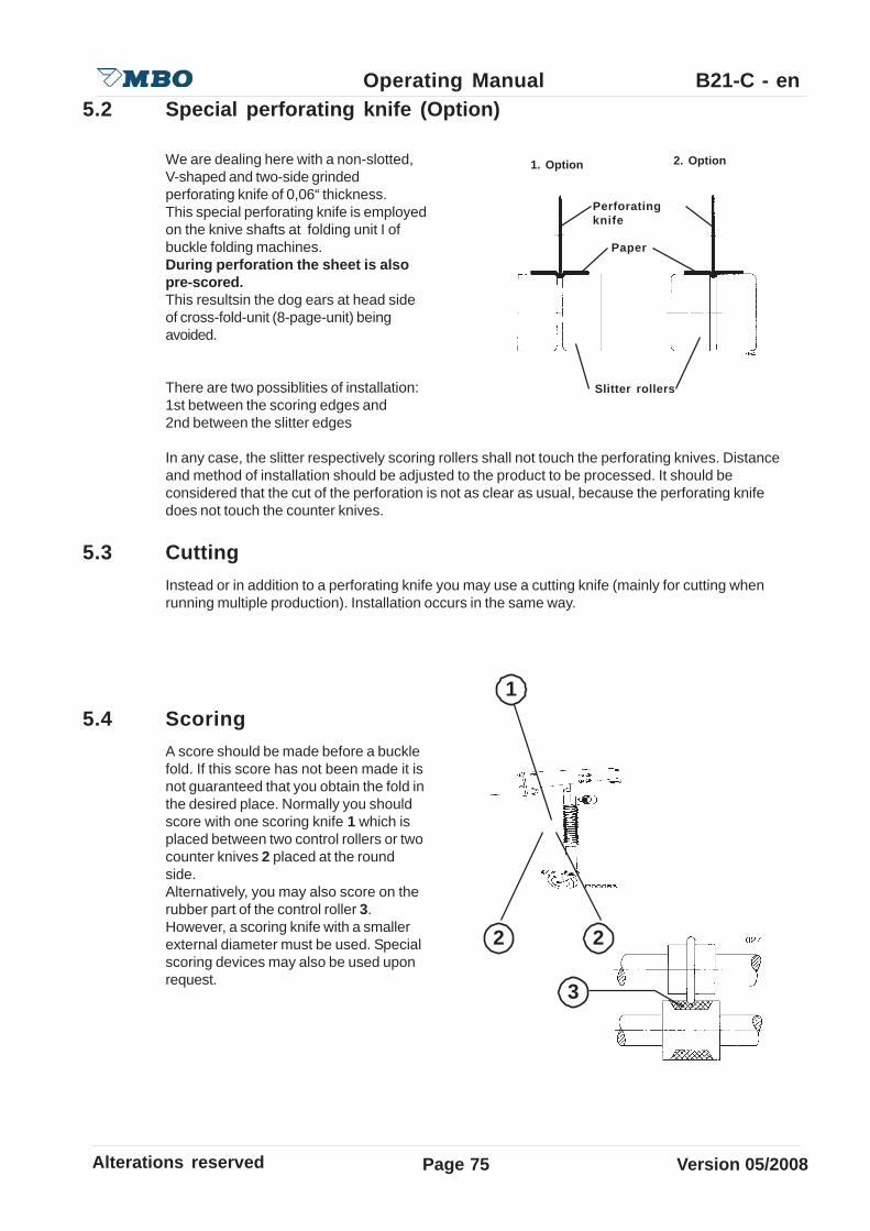
Alterations reserved Version 05/2008
Operating Manual B21-C - en
Page 75
5.2 Special perforating knife (Option)
We are dealing here with a non-slotted,V-shaped and two-side grindedperforating knife of 0,06“ thickness.This special perforating knife is employedon the knive shafts at folding unit I ofbuckle folding machines.During perforation the sheet is alsopre-scored.This resultsin the dog ears at head sideof cross-fold-unit (8-page-unit) beingavoided.
There are two possiblities of installation:1st between the scoring edges and2nd between the slitter edges
In any case, the slitter respectively scoring rollers shall not touch the perforating knives. Distanceand method of installation should be adjusted to the product to be processed. It should beconsidered that the cut of the perforation is not as clear as usual, because the perforating knifedoes not touch the counter knives.
5.3 CuttingInstead or in addition to a perforating knife you may use a cutting knife (mainly for cutting whenrunning multiple production). Installation occurs in the same way.
5.4 ScoringA score should be made before a bucklefold. If this score has not been made it isnot guaranteed that you obtain the fold inthe desired place. Normally you shouldscore with one scoring knife 1 which isplaced between two control rollers or twocounter knives 2 placed at the roundside.Alternatively, you may also score on therubber part of the control roller 3.However, a scoring knife with a smallerexternal diameter must be used. Specialscoring devices may also be used uponrequest.
1. Option 2. Option
Perforatingknife
Paper
Slitter rollers
1
2
3
2
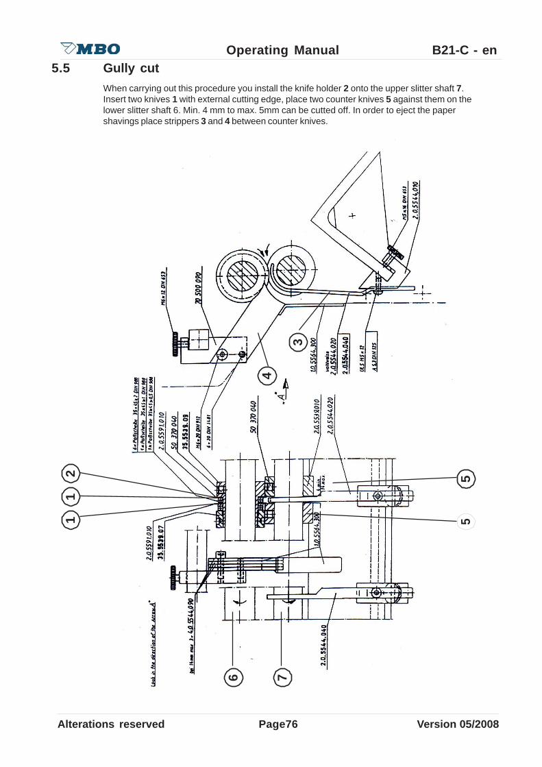
Page76Alterations reserved Version 05/2008
Operating Manual B21-C - en5.5 Gully cut
When carrying out this procedure you install the knife holder 2 onto the upper slitter shaft 7.Insert two knives 1 with external cutting edge, place two counter knives 5 against them on thelower slitter shaft 6. Min. 4 mm to max. 5mm can be cutted off. In order to eject the papershavings place strippers 3 and 4 between counter knives.
11
2
55
6 74
3
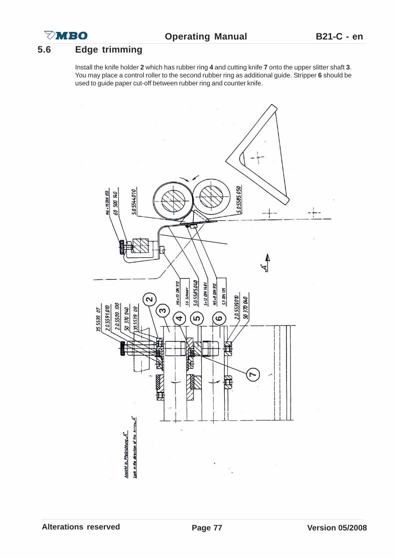
Alterations reserved Version 05/2008
Operating Manual B21-C - en
Page 77
5.6 Edge trimming
Install the knife holder 2 which has rubber ring 4 and cutting knife 7 onto the upper slitter shaft 3.You may place a control roller to the second rubber ring as additional guide. Stripper 6 should beused to guide paper cut-off between rubber ring and counter knife.
23
4 5 6
7

Page78Alterations reserved Version 05/2008
Operating Manual B21-C - en
If you obtain angled cut or badly guided paper trim-off you may also install the knife folder onto thelower instead of the upper slitter shaft. Moreso, you may also install the knife with its cut edgeinto the direction of the folding product. However, it mostly depends on the paper thickness orrunning direction.Experiences shows that the following alternative of installation reveals in the best result:knife top, counter knife bottom, cut edge of top knife into direction of paper cut-off. Paper cut-off isguided by rubber ring.
5.7 Slitter shaft guard
The flap 5 is a safety guard for the slitter shafts and it is electrically locked.For insertion of other aggregates, regulate flat 5 , release knurled nut 7 , pull the grip 8 up andscrew-in the knurled nut 7.
Danger before falling down of the opened protection hood.Negligence can cause heavy injuries through bruise of body part.Be sure that in work with opened noise hoods this is completely opened tothe attack.
Danger of running machine parts.Negligence can cause heavy personal injuries or extensive damages.Report each audible/visible security-related change of the machine to theresponsible for that in your business.
56
7
8
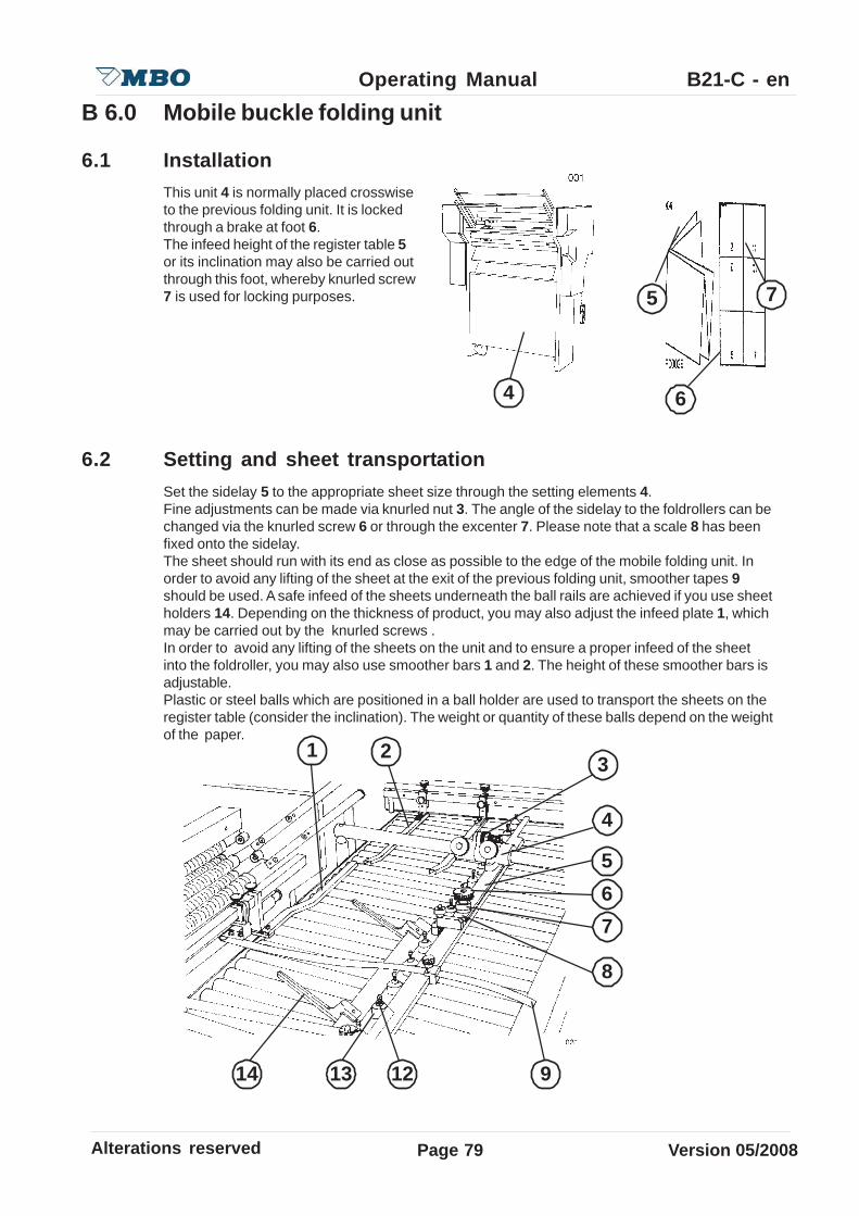
Alterations reserved Version 05/2008
Operating Manual B21-C - en
Page 79
B 6.0 Mobile buckle folding unit
6.1 InstallationThis unit 4 is normally placed crosswiseto the previous folding unit. It is lockedthrough a brake at foot 6.The infeed height of the register table 5or its inclination may also be carried outthrough this foot, whereby knurled screw7 is used for locking purposes.
6.2 Setting and sheet transportationSet the sidelay 5 to the appropriate sheet size through the setting elements 4.Fine adjustments can be made via knurled nut 3. The angle of the sidelay to the foldrollers can bechanged via the knurled screw 6 or through the excenter 7. Please note that a scale 8 has beenfixed onto the sidelay.The sheet should run with its end as close as possible to the edge of the mobile folding unit. Inorder to avoid any lifting of the sheet at the exit of the previous folding unit, smoother tapes 9should be used. A safe infeed of the sheets underneath the ball rails are achieved if you use sheetholders 14. Depending on the thickness of product, you may also adjust the infeed plate 1, whichmay be carried out by the knurled screws .In order to avoid any lifting of the sheets on the unit and to ensure a proper infeed of the sheetinto the foldroller, you may also use smoother bars 1 and 2. The height of these smoother bars isadjustable.Plastic or steel balls which are positioned in a ball holder are used to transport the sheets on theregister table (consider the inclination). The weight or quantity of these balls depend on the weightof the paper.
4 6
75
12
1 23
4
5
6
7
14 13 9
8

Page80Alterations reserved Version 05/2008
Operating Manual B21-C - enLight (porous) paper = plastic or less ballsHeavy paper = steel or more balls
A screw with a spring is located on top of this ball holder 12. If you turn in this screw it will avoidthe ball jamping during fast production.
You may place a stop switch to the exits of the folding units which will turn off the machine incase of jam-ups (optional).
The foldrollers, sheet deflectors, slitter shafts and noise damping device are used and adjusted asdescribed previously.
6.3 Electrical connection
The electrical connection occurs throughthe cable with power plug 1 and controlplug 2 at control cabinet of the previousfolding unit.
A dummy plug 3 should be plugged intothe control socket 4 for the control cable,if no subsequent folding unit or delivery isused.
6.4 Control panel 5 Red mushroom button for EMERGENCY-STOP 6 Red button for machine STOP 7 Black button for machine START 8 White button for SHEET INFEED 9 White button for SHEET INFEED one Sheet10 Potentiometer for electronical speed regulation
6.5 Foldrollers and slitter shafts at subsequent folding unitsSettings of foldrollers and slitter shafts should be carried out as described under item B7.You will find the MBO setting instructions of the most commonly folds under item D1 - D3.
Danger of electric tension.Negligence can cause, heavy injuries or death.Report damaged electrical connections to respnsible supervisor.
3
4
5 6 7 8 9
12
10
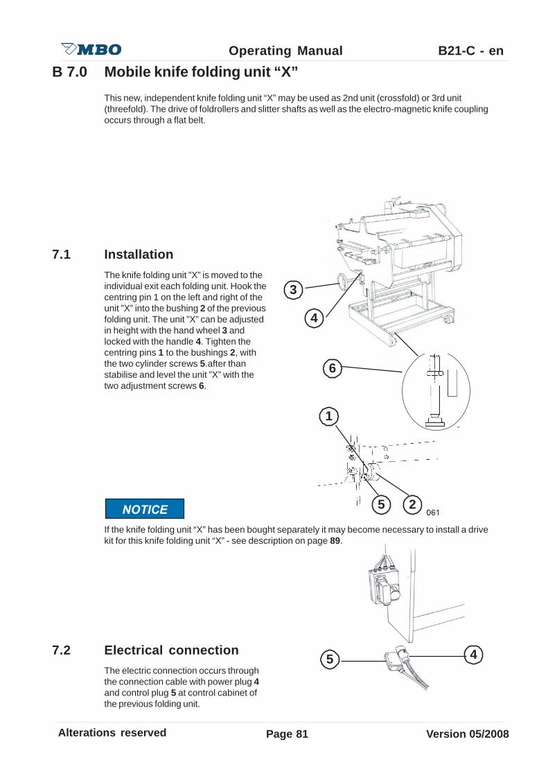
Alterations reserved Version 05/2008
Operating Manual B21-C - en
Page 81
B 7.0 Mobile knife folding unit “X”This new, independent knife folding unit “X” may be used as 2nd unit (crossfold) or 3rd unit(threefold). The drive of foldrollers and slitter shafts as well as the electro-magnetic knife couplingoccurs through a flat belt.
7.1 InstallationThe knife folding unit ”X” is moved to theindividual exit each folding unit. Hook thecentring pin 1 on the left and right of theunit ”X” into the bushing 2 of the previousfolding unit. The unit ”X” can be adjustedin height with the hand wheel 3 andlocked with the handle 4. Tighten thecentring pins 1 to the bushings 2, withthe two cylinder screws 5.after thanstabilise and level the unit ”X” with thetwo adjustment screws 6.
If the knife folding unit “X” has been bought separately it may become necessary to install a drivekit for this knife folding unit “X” - see description on page 89.
7.2 Electrical connectionThe electric connection occurs throughthe connection cable with power plug 4and control plug 5 at control cabinet ofthe previous folding unit.
25
1
3
4
6
5 4

Page82Alterations reserved Version 05/2008
Operating Manual B21-C - en7.3 Setting and sheet transportation
7.3.1 Knife folding unit “X” as first crossfold
Set the sheet stop 2 through the centraladjustment 6 to the sheet size.Measurements can be read-off at toothedbelt 5 or through the marked indication atguide rail. Angular adjustments may beobtained through the central adjustment,as mentioned under item 4.2, page 52 forbuckle plates. In addition, the sheet stopmay also be fixed through the hexagonscrews 4 (if heavy sheets areprocessed).If the sheet stop is not used you may liftit so that only parallel folded sheets willpass underneath.Turn OFF coupling of knife, i.e. activateswitch 7 to the middle position.Move a sheet to the sheet stop and putthe adjustable sidelay 3 with fineadjustment 1 to the sheet edge. Set thespring sidelay 2 to the opposite sheetedge. By means of a scale which issituated at the sheet stop 8, you maypre-set the sidelays to the correspondingsheet size.
The sheet should run as close as possible to the sidelay. The spring sidelay should not guide thesheet to the fixed sidelay but rather to slightly hold against it.
12
3
4 5 6
7
8
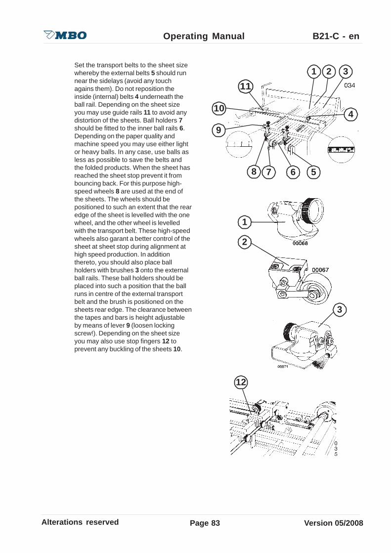
Alterations reserved Version 05/2008
Operating Manual B21-C - en
Page 83
Set the transport belts to the sheet sizewhereby the external belts 5 should runnear the sidelays (avoid any touchagains them). Do not reposition theinside (internal) belts 4 underneath theball rail. Depending on the sheet sizeyou may use guide rails 11 to avoid anydistortion of the sheets. Ball holders 7should be fitted to the inner ball rails 6.Depending on the paper quality andmachine speed you may use either lightor heavy balls. In any case, use balls asless as possible to save the belts andthe folded products. When the sheet hasreached the sheet stop prevent it frombouncing back. For this purpose high-speed wheels 8 are used at the end ofthe sheets. The wheels should bepositioned to such an extent that the rearedge of the sheet is levelled with the onewheel, and the other wheel is levelledwith the transport belt. These high-speedwheels also garant a better control of thesheet at sheet stop during alignment athigh speed production. In additionthereto, you should also place ballholders with brushes 3 onto the externalball rails. These ball holders should beplaced into such a position that the ballruns in centre of the external transportbelt and the brush is positioned on thesheets rear edge. The clearance betweenthe tapes and bars is height adjustableby means of lever 9 (loosen lockingscrew!). Depending on the sheet sizeyou may also use stop fingers 12 toprevent any buckling of the sheets 10.
1 2 3
8
10
11
4
567
9
12
1
2
3

Page84Alterations reserved Version 05/2008
Operating Manual B21-C - en7.3.2 Knife folding unit “X” as 2nd crossfold (threefold)
If this unit should be used as threefold unit (configuration 44X), i.e. after the 2nd folding unit, thesheets must run centrally beneath the folding knife in knife folding unit “X”. In order to ensure asafe transfer of the sheets from the 1st folding unit to the guide rail of the 2nd folding unit aconveyor table (option) must be installed on the exit of the 1st folding unit (see page 89)
7.3.3 Foldrollers / Slitter shafts of the knife folding unit “X”
In order to achieve the required setting of the rollers you should press the lever 2 at caliper settingelement 5 and insert a strip of paper 4 between the pressure plate 6 and pressure bar. Afterwerds,turn the handwheel of the machine and, in doing so, check whether the paper strip goes throughthe foldrollers.When you turn the knurled screw clockwise the pressure on the foldrollers becomes less, but ifyou turn knurled screw counter-clockwise, the pressure on the foldrollers has increased. After thisbasic setting, reset the adjusting ring 3 to 0-position in order to enable a quick readjustment offoldrollers into their original position. The setting of the slitter shafts occurs in the same manner.Depending on the kind of fold you may now insert the paper strip to achieve the desired papergauge between the pressure plate and pressure bar.
The slitter shafts 7 of the knife folding unit “X“ are positioned beneath the foldrollers and are easilychangeable through the quick setting elements 8 (see B5.0 on page 69)
MBO setting instructions of the most commonly folds will follow on pages D1-D3.
Danger of running machine parts.Negligence can cause heavy personal injuries or extensive damages.• Never carry out foldroller settings while machine is still running.• Even manual foldroller setting by the handwheel.
1
2
3 4 5 6
7 8

Alterations reserved Version 05/2008
Operating Manual B21-C - en
Page 85
7.3.4 Knife setting
7.3.4.1 Depth setting of knife
When setting the knife 7.31 turn the handwheel manually so that the sheet is moved into thefoldrollers by the knife.
To make sure that the sheet is taken correctly from the foldrollers, height corrections of the knifecan be made, however, this depends on the thickness of product.
Such height corrections can be madethrough locking handle 1. Clockwiseturning of locking handle - knife movesupwards. Counter-clockwise turning oflocking handle - knife moves downwards.
7.3.4.2 Horizontal knife setting
The precise setting of the knife into thehorizontal position is responsible for anexact sheet infeed and the subsequentperforating of the sheet.
In order to avoid that the sheet is pushed too hard against the sheet stop you may change thehorizontal knife position with locking lever 2!
If the sheet is not pulled parallel into the foldrollers it means that the knife is not in a horizontalposition. This can be noticed if the sheet, when it is pulled into the foldrollers, is pushed to strongagainst the sheet stop or if it runs off from the sheet stop. If the sheet is pushed too strongagainst the sheet stop you have to set the declination of the knife somewhat higher by clockwiseturning the clamping lever. If the sheet is pushed off from the sheet stop you should set the knifedeeper by turning the clamping lever counter-clockwise.These settings can be carried out withouttools by using the locking handles.
For extreme horizontal positioning the knife must be set completely higher, if necessary!
1 2 3
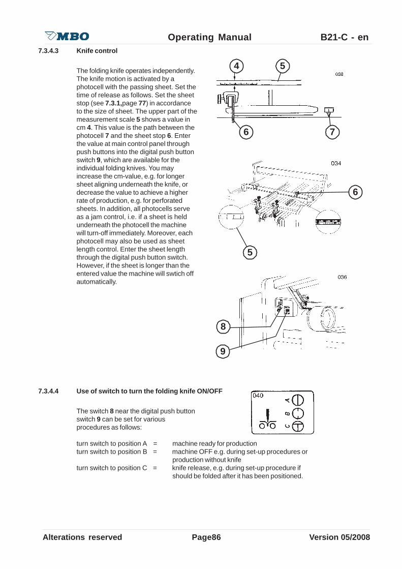
Page86Alterations reserved Version 05/2008
Operating Manual B21-C - en7.3.4.3 Knife control
The folding knife operates independently.The knife motion is activated by aphotocell with the passing sheet. Set thetime of release as follows. Set the sheetstop (see 7.3.1,page 77) in accordanceto the size of sheet. The upper part of themeasurement scale 5 shows a value incm 4. This value is the path between thephotocell 7 and the sheet stop 6. Enterthe value at main control panel throughpush buttons into the digital push buttonswitch 9, which are available for theindividual folding knives. You mayincrease the cm-value, e.g. for longersheet aligning underneath the knife, ordecrease the value to achieve a higherrate of production, e.g. for perforatedsheets. In addition, all photocells serveas a jam control, i.e. if a sheet is heldunderneath the photocell the machinewill turn-off immediately. Moreover, eachphotocell may also be used as sheetlength control. Enter the sheet lengththrough the digital push button switch.However, if the sheet is longer than theentered value the machine will swtich offautomatically.
7.3.4.4 Use of switch to turn the folding knife ON/OFF
The switch 8 near the digital push buttonswitch 9 can be set for variousprocedures as follows:
turn switch to position A = machine ready for productionturn switch to position B = machine OFF e.g. during set-up procedures or
production without knifeturn switch to position C = knife release, e.g. during set-up procedure if
should be folded after it has been positioned.
4 5
6 7
6
9
8
5

Alterations reserved Version 05/2008
Operating Manual B21-C - en
Page 87
B 8.0 Noise damping device
Noise damping and protection device.The noise hood consists of two parts for insertions or adjustments. Push the hood upwards bymeans of the grips 1 and 2. Fine adjustments at buckle plates 1 and 3 can be made through theopenings 3 and 4.
5 see page 73- 5.7
Danger before falling down of the opened protection hood.Negligence can cause heavy injuries through bruise of body part.Be sure that in work with opened noise hoods this is completely opened tothe attack.
Danger of running machines part during the installation working.Negligence can cause heavy personal injuries or extensive damages.• Never grasp into the running machine in!• Keep protection hood close during production.
1
3
4
5
6 78
2

Page88Alterations reserved Version 05/2008
Operating Manual B21-C - enB 9.0 Stream delivery
9.1 Mobile stream delivery A56The mobile stream delivery may be placed at each exit (outlet) of a folding machine. Move thestream delivery into the required position and secure the caster wheels with foot brakes 10.Use the hand crank 11 for height adjustments. A slight angle of the infeed table 12 is advisableand can be acheived using the lever 13.
Since the tapes of the infeed table arefixed only the transport rollers 14 shouldbe set in accordance to the sheet size.In order to guide the sheets underneaththe transport rollers, fit rods 15 onto thefrontal transport rollers. In case ofmultiple production affix the reartransport rollers onto the front rod.The folded sheets fall onto the collectorsheet 16 which may be adjusted by asetting spindle 17 located beneath thecollector sheet. Two moveable magneticposts serve as sheet stop.
The electric power is supplied asdescriped under 7.2 page 76. The speedmay be regulated through thepotentiometer located at the terminal boxof the stream delivery.
If the machine is operated without a stream delivery, e.g. during set-up of the machine, a dummyplug 2 must be plugged into the control socket 1 “Machine Control” of the previous folding unit.
The infeed table must be held with your other hand when you activate thelever!
12
1
2
18
17
16
15
14
13
10
11

Alterations reserved Version 05/2008
Operating Manual B21-C - en
Page 89
9.2 Hook-on stream delivery SE500/3The deliveries SE500/3 can be suspended at unit I and II. They are suspended at the holder 1 andsnapped-on in three different height position3 with the Snap-On hoop 2. The transport rollersshould be set in accordance to the sheet size. The electric connection occurs through theconnection cable with power plug and control plug 5 and 6 at control cabinet of the folding unit.The speed can be regulated through the button 7 located at the terminal box of the streamdelivery.
8 Emergency stop 9 Red button MACHINE STOP10 Black button MACHINE START11 White button SHEET INFEED
If the machine is operated without a stream delivery (during set-up of the machine), a dummy plugmust be plugged into the control socket ”machine control” of the previous folding unit.
Danger of dump and slipping of the delivery.Negligence can cause heavy personal injuries or extensive damages.Be sure that the hook-on stream delivery is correctly positioned in support1
2
109
11
1
3
4
5 6
7
8
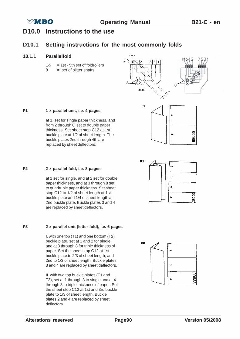
Page90Alterations reserved Version 05/2008
Operating Manual B21-C - en
P1 1 x parallel unit, i.e. 4 pages
at 1, set for single paper thickness, andfrom 2 through 8, set to double paperthickness. Set sheet stop C12 at 1stbuckle plate at 1/2 of sheet length. Thebuckle plates 2nd through 4th arereplaced by sheet deflectors.
P2 2 x parallel fold, i.e. 8 pages
at 1 set for single, and at 2 set for doublepaper thickness, and at 3 through 8 setto quadruple paper thickness. Set sheetstop C12 to 1/2 of sheet length at 1stbuckle plate and 1/4 of sheet length at2nd buckle plate. Buckle plates 3 and 4are replaced by sheet deflectors.
P3 2 x parallel unit (letter fold), i.e. 6 pages
I. with one top (T1) and one bottom (T2)buckle plate, set at 1 and 2 for singleand at 3 through 8 for triple thickness ofpaper. Set the sheet stop C12 at 1stbuckle plate to 2/3 of sheet length, and2nd to 1/3 of sheet length. Buckle plates3 and 4 are replaced by sheet deflectors.
II. with two top buckle plates (T1 andT3), set at 1 through 3 to single and at 4through 8 to triple thickness of paper. Setthe sheet stop C12 at 1st and 3rd buckleplate to 1/3 of sheet length. Buckleplates 2 and 4 are replaced by sheetdeflectors.
D10.0 Instructions to the use
D10.1 Setting instructions for the most commonly folds
10.1.1 Parallelfold
1-5 = 1st - 5th set of foldrollers8 = set of slitter shafts
8 8

Alterations reserved Version 05/2008
Operating Manual B21-C - en
Page 91
P4 2 x parallel unit (accordian fold), i.e. 6 pages
set at 1 and 2 to single thickness ofpaper, and at 3 through 8 to triplethickness of paper. Set sheet stop C12at buckle plate T1 and T2 to 1/3 of sheetlength. Buckle plates 3 and 4 arereplaced by sheet deflectors.
P5 3 x parallel unit (accordian fold), i.e. 8 pages
set at 1 through 3 for single thicknessand at 4 through 8 to quarduplethickness of paper. Set sheet stop C12to 1/4 of sheet length of buckle plates1st to 3rd. The 4th buckle plate isreplaced by sheet deflector.
P6 4 x parallel unit (accordian fold), i.e. 10 pages
set at 1 through 4 to single paperthickness and at 5 through 8 to fivefoldthickness of paper. Set the sheet stopC12 to 1/5 of sheet length at buckle plate1st through 4th.
P7 3 x parallel unit (letter fold), i.e. 12 pages
set at 1 to single paper thickness, at 2through 4 to double thickness of paperand at 5 through 8 to sixfold thickness ofpaper. Sheet stop C 12 should be set 1/2of sheet length at first buckle plate, andto 1/6 of sheet length at 2nd and 4thbuckle plate. The 3rd buckle plate isreplaced by a sheet deflector.
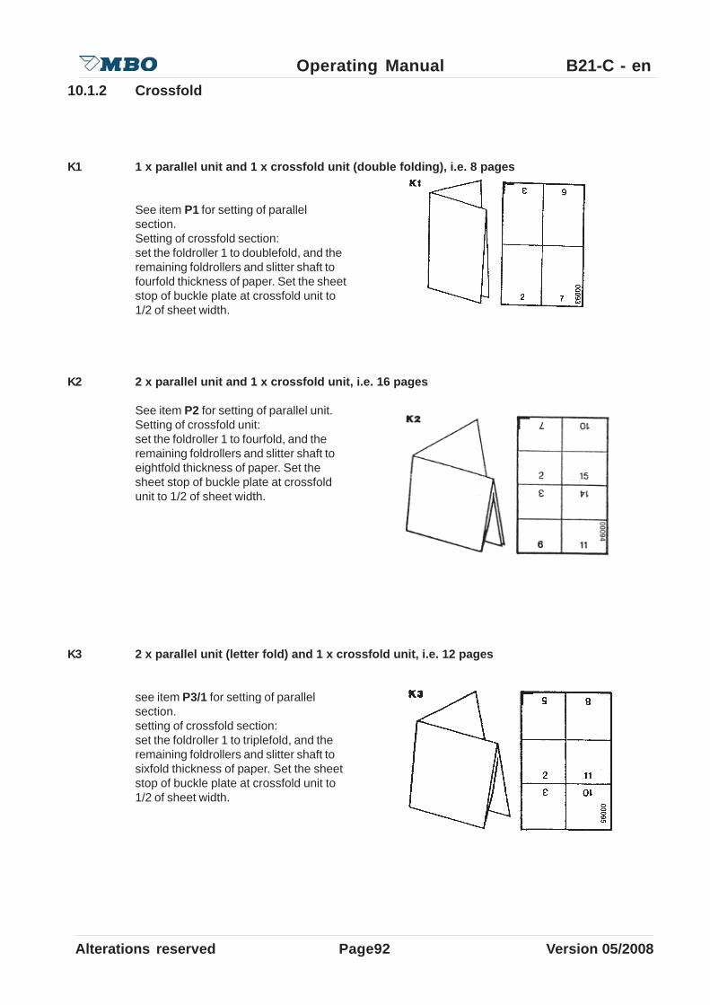
Page92Alterations reserved Version 05/2008
Operating Manual B21-C - en10.1.2 Crossfold
K1 1 x parallel unit and 1 x crossfold unit (double folding), i.e. 8 pages
See item P1 for setting of parallelsection.Setting of crossfold section:set the foldroller 1 to doublefold, and theremaining foldrollers and slitter shaft tofourfold thickness of paper. Set the sheetstop of buckle plate at crossfold unit to1/2 of sheet width.
K2 2 x parallel unit and 1 x crossfold unit, i.e. 16 pages
See item P2 for setting of parallel unit.Setting of crossfold unit:set the foldroller 1 to fourfold, and theremaining foldrollers and slitter shaft toeightfold thickness of paper. Set thesheet stop of buckle plate at crossfoldunit to 1/2 of sheet width.
K3 2 x parallel unit (letter fold) and 1 x crossfold unit, i.e. 12 pages
see item P3/1 for setting of parallelsection.setting of crossfold section:set the foldroller 1 to triplefold, and theremaining foldrollers and slitter shaft tosixfold thickness of paper. Set the sheetstop of buckle plate at crossfold unit to1/2 of sheet width.

Alterations reserved Version 05/2008
Operating Manual B21-C - en
Page 93
10.1.3 Threefold
K4 2 x parallel fold (accordian) and 1 x crossfold, i.e. 12 pages
see item P4 for setting of parallel unit.setting of crossfold section:set the foldroller 1 to threefold, and theremaining foldrollers and slitter shaft tosixfold of paper thickness and sheetstops at crossfold unit to 1/2 of sheetwidth.
K5 1 x parallel unit, 1 x crossfold unit and 1 x threefold unit (threefold right-angle), i.e. 16pages
see item K1 for setting of parallel andcrossfold unitsetting of threefold section:set the foldroller 1 to fourfold, and theremaining foldrollers and slitter shaft toeightfold of paper thickness and sheetstop at threefold section to 1/4 of sheetlength.
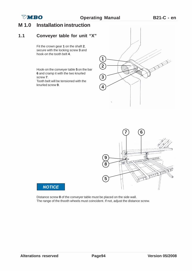
Page94Alterations reserved Version 05/2008
Operating Manual B21-C - enM 1.0 Installation instruction
1.1 Conveyer table for unit “X”
Fit the crown gear 1 on the shaft 2,secure with the locking screw 3 andhook-on the tooth belt 4.
Hook-on the conveyer table 5 on the bar6 and cramp it with the two knurledscrew 7.Tooth belt will be tensioned with theknurled screw 9.
Distance screw 8 of the conveyer table must be placed on the side wall.The range of the thooth wheels must coincident. If not, adjust the distance screw.
1
3
4
5
7
8
6
2
9

Alterations reserved Version 05/2008
Operating Manual B21-C - en
Page 95
M2.0 Maintenance protocolYou can use this sheet (a copy) like a maintenance protocol or a checklist, but don´t forget theother checkpoints at item 4.2, page 52.
:.on-retpahC noitarepO llavretnI etaD erutangiS
ecnanetniaM 2.2.4 niahcredeeF htnomyreve
1.1.4 taepatretsigeRelbatretsiger
htnomyreve
2.1.4 roftlebevirDleehwnoitcus
htnomyreve
3.1.4 roftlebevirD-tinulellarapdnarellordlof
stfahsrettilshtnomyreve
5.1.4
4.1.4 lellarapevirdniaM htnomyreve
6.1.4
ssorcnotlebevirDretsigerreirrac
dnagp8-elbattinugp61
htnomyreve
7.2.4 retlifgninaelCegdirtrac
fosruoh05yrevenoitarepo
7.2.4 retlifegnahcxEegdirtrac
htnom6yreve
noitacifirbuL 1.2.4 dnaenihcamniaMelbattnemngila
htnomyreve
2.2.4 elipniahcevirDredeef
htnomyreve
gninaelC 6.2.4 srellordloF yrassecennehw
srosneS yadyreve
rellorrenaelC yadyreve
enihcamelbavoMstraP
hcaeretfAnoitcudorp
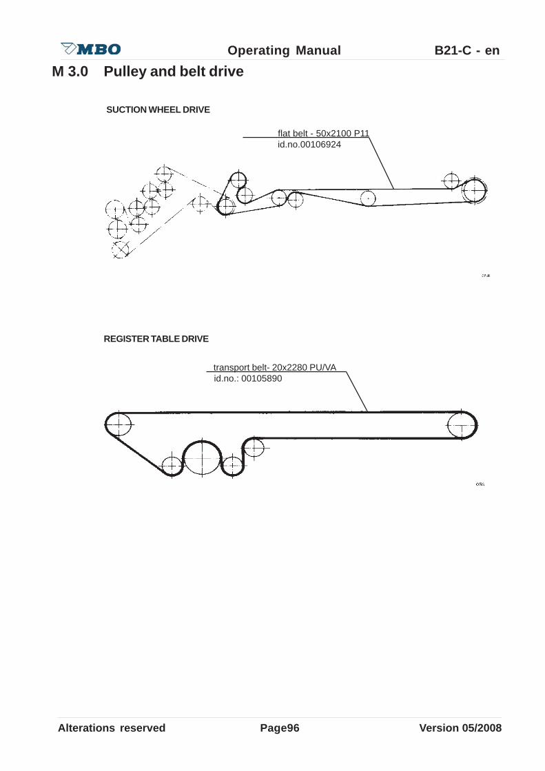
Page96Alterations reserved Version 05/2008
Operating Manual B21-C - en
flat belt - 50x2100 P11 id.no.00106924
SUCTION WHEEL DRIVE
M 3.0 Pulley and belt drive
transport belt- 20x2280 PU/VA id.no.: 00105890
REGISTER TABLE DRIVE
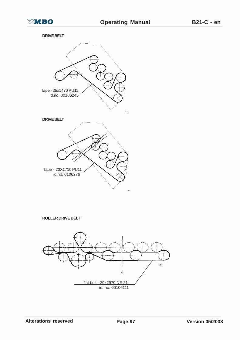
Alterations reserved Version 05/2008
Operating Manual B21-C - en
Page 97
flat belt - 20x2970 NE 21 id. no. 00106111
ROLLER DRIVE BELT
DRIVE BELT
DRIVE BELT
Tape - 20X1710 PU11 id.no. 0106276
Tape - 25x1470 PU11 id.no. 00106245
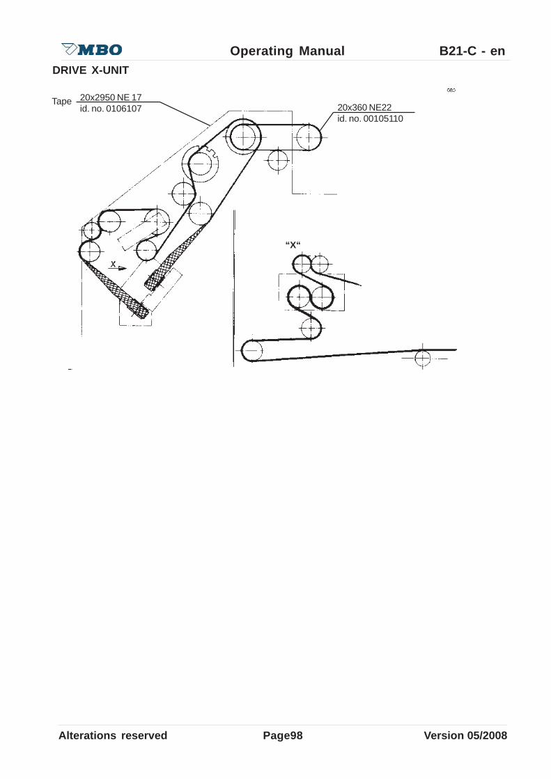
Page98Alterations reserved Version 05/2008
Operating Manual B21-C - enDRIVE X-UNIT
20x360 NE22id. no. 00105110
“X“
20x2950 NE 17id. no. 0106107
Tape

Alterations reserved Version 05/2008
Operating Manual B21-C - en
Page 99

Page100Alterations reserved Version 05/2008
Operating Manual B21-C - enM 4.0 Out of order
4.1 Statements for the storage• Test the accomodations concerning the temperature and humidity. The ideal warehouse
temperature isbetween 59- 82°F. As higher the humidity, higher the risk of corrosion.• Notice the machine weight before selection of the accomodations.• Prepare the transmissions and motors for storage. The prerequisites are different from case to
case.For this reason, ask the supplier of the transmissions/motors and read the respectivehandling instructions.
• Clean the machine thoroughly of dirt and dust, however do not use water due to the risk of thecorrosion.
• Use a forklift to carry the machine.• Cover the machine with foil.
4.2 Environment and disposal• Disposal old machine and there components according to environment laws:
Ask for disposal possibilities to the municipal disposal services or private disposers.
Distinguish at the same time between:
• Annihilation (acts annihilation)• Recycling (plastic packaging)• Disposal (pollutant disposal).

Alterations reserved Version 05/2008
Operating Manual B21-C - en
Page 101
4.3 Disposal of the old machineDetoxify the old machine:
• over the supplier• over a disposal and wrecking companys• over the own firm
4.3.1 Disposal with order at the supplier
Give the order of the disposal to your supplier. . The old machine becomes either taken inpayment or correctly dismantled and detoxified. This way you avoid all inconvenients of theprocess.
4.3.2 Disposal with order at a disposal and wrecking
You can transmit also the order to a nearby disposal and wrecking company, that are also trustedwith this kind of disposal
4.3.3 Disposal over the own firm
You have the possibility to dispose the old machine in your own company and with own technicalpersonnel.Please, notice the fact that you may need a separate approval for the transport of waste as wellas for the disposal. Let confirm in writing the lawful disposal.
4.4 Ground-water protectionFollow the valid regulations and laws of the avoidance of soiling of the ground-water:

MBO Binder GmbH & Co. KGPostfach 1169D-71567 Oppenweiler
Tel.: +49 (0) 71 91 / 46 – 0Fax: +49 (0) 71 91 / 46 – 34http://[email protected]
MBO Deutschland
MBO Portugal MBO Binder GmbH & Co.Maquinas Graficas, LdaRua Joaquim Alves da Silva 240, 420 e 570P-4455-473 Perafita / Portugal
Tel.: +351 22 99 82 - 200Fax: +351 22 99 82 - 201http://[email protected]
MBO Herzog & Heymann
MBO Binder GmbH & Co. of America400 Highland DriveWestampton, NJ 08060 / USA
Tel.: +1 6 09267 - 2900Fax: +1 6 09 267 - 14 77http://www.mboamerica.comhttp://www.mboamerica.com
MBO Frankreich MBO France SASZ. A. Burospace n° 3Route de Gisy B.P. 33F-91571 Bievres Cedex
Tel.: +33 1 69 35 50 - 90Fax: +33 1 69 35 50 - 99http://[email protected]
MBO Amerika
Herzog & Heymann GmbH + Co. KGPostfach 110355D-33663 Bielefeld
Tel.: +49 (0) 71 91 / 46 – 0Fax: +49 (0) 71 91 / 46 – 34
http://[email protected]
MBO China MBO Binder Graphic Systems (Beijing) Co.Ltd.No.3 Building, XingSehng Industry Park,No.7 Tong Ji Zhong Lu, BDA,Beijing 100176
Tel.: +86 10 6786 2741 69 35 50 - 90Fax: +86 10 6786 2743http://www.mbo-folder.comhttp://www.mbo-folder.com
Related Documents