Proceedings of ACOUSTICS 2016 9-11 November 2016, Brisbane, Australia Breathing response in a statically indeterminate cracked rotor Declan Williams and Helen Wu School of Computing, Engineering & Mathematics, Western Sydney University, Sydney, Australia ABSTRACT A new iterative-analytical approach to determining the static behaviour of a cracked rotor has been developed and applied to a statically indeterminate model. The model subjects the cracked shaft to out-of-plane bending due the inclusion of an offset dynamic force. The interaction between fixed supports and the variable shaft stiffness caused by a breathing crack make the model analytically unsolvable. The presented iterative algorithm for determining the breathing state of the crack makes the model analytically solvable for the support reactions and the elastic deflections. The algorithm rapidly converges, requiring typically fewer than 4 iterations to achieve stable results. The breathing response for a particular set of model parameters has been evaluated and is presented. 1. INTRODUCTION Cracked shafts in rotating machinery can lead to catastrophic mechanical failure and costly loss of productivity. Early detection of surface cracks through vibration diagnostics is of great interest in heavy industry. Vibration characteristics of cracked rotors are still not completely understood. Numerical simulations play an important role in current research. Much of this research has been conducted into the problem of mathematically modelling the mechanical behaviour of a cracked rotor. Approaches to doing this have varied depending on the aim of the researcher. Static and quasi-static problems have been frequently studied using 3D finite element models that use nonlinear contact surfaces to simulate a crack (Bachschmid and Tanzi, 2004) (Rubio et al., 2014). Another technique used to statically model cracked rotors uses Euler beam theory and accounts for the crack by a discontinuity in the rotation of the shaft at the crack location the value of which is determined using the strain energy release relate (SERR) (Rubio et al., 2011). For studying dynamic problems like critical speeds, and shaft orbital characteristics, it is common to model the shaft using beam finite elements with the crack's influence accounted for a reduced second moment of area for one or more of the elements (Spagnol and Wu, 2014) (Al-Shudeifat and Butcher, 2011). The reduced section modulus at the crack location is a function of the opening percentage (i.e. the breathing state) of the crack. This in turn is related to the bending direction of the shaft at the crack location. The crack element will only assume the rigidity of an un-cracked shaft when the crack is fully closed. Equations for the approximate 2nd moments of area were derived by Al-Shudeifat and Butcher (2011) for the case of a horizontal shaft subject only to static weight forces. These equations were developed further by Spagnol and Wu (2014) to consider dynamic forces in a Jeffcott rotor. This paper presents an iterative method of analysing the breathing of a statically indeterminate cracked rotor subject to out of plane bending loads. 2. MODEL DESCRIPTION Consider a rotor supported by fixed ends is subjected to a distributed weight force, m s g/L, two concentrated weight forces, m d g, and dynamic force due to an unbalanced mass, F un . A crack exists at z = L 0 which is modelled as region of the shaft of length L/n with a reduced stiffness, where n is an integer greater than 1 and L is the length of the shaft. The amount by which the stiffness is reduced depends on the crack's breathing state. The concentrated mass forces are from two discs mounted to the shaft, with the unbalance mass presenting in one of them. The rotation of the shaft is quantified by the angular displacement, θ, between midpoint of the crack face and the negative global Y axis (shown in Figure 1). The phase of the unbalanced mass is the angle β, from the crack front. A method for determining the static behaviour of this model with a crack located between the two discs is as follows. Because the shaft is supported by cantilevers at both ends, the problem is statically indeterminate. Thus the support reactions are dependent on the shaft's stiffness. The shaft's stiffness is dependent on the breathing state of the crack. ACOUSTICS 2016 Page 1 of 9

Welcome message from author
This document is posted to help you gain knowledge. Please leave a comment to let me know what you think about it! Share it to your friends and learn new things together.
Transcript

Proceedings of ACOUSTICS 2016 9-11 November 2016, Brisbane, Australia
Breathing response in a statically indeterminate cracked rotor
Declan Williams and Helen Wu
School of Computing, Engineering & Mathematics, Western Sydney University, Sydney, Australia
ABSTRACT A new iterative-analytical approach to determining the static behaviour of a cracked rotor has been developed and applied to a statically indeterminate model. The model subjects the cracked shaft to out-of-plane bending due the inclusion of an offset dynamic force. The interaction between fixed supports and the variable shaft stiffness caused by a breathing crack make the model analytically unsolvable. The presented iterative algorithm for determining the breathing state of the crack makes the model analytically solvable for the support reactions and the elastic deflections. The algorithm rapidly converges, requiring typically fewer than 4 iterations to achieve stable results. The breathing response for a particular set of model parameters has been evaluated and is presented.
1. INTRODUCTION Cracked shafts in rotating machinery can lead to catastrophic mechanical failure and costly loss of
productivity. Early detection of surface cracks through vibration diagnostics is of great interest in heavy industry. Vibration characteristics of cracked rotors are still not completely understood. Numerical simulations play an important role in current research. Much of this research has been conducted into the problem of mathematically modelling the mechanical behaviour of a cracked rotor. Approaches to doing this have varied depending on the aim of the researcher. Static and quasi-static problems have been frequently studied using 3D finite element models that use nonlinear contact surfaces to simulate a crack (Bachschmid and Tanzi, 2004) (Rubio et al., 2014). Another technique used to statically model cracked rotors uses Euler beam theory and accounts for the crack by a discontinuity in the rotation of the shaft at the crack location the value of which is determined using the strain energy release relate (SERR) (Rubio et al., 2011).
For studying dynamic problems like critical speeds, and shaft orbital characteristics, it is common to model the shaft using beam finite elements with the crack's influence accounted for a reduced second moment of area for one or more of the elements (Spagnol and Wu, 2014) (Al-Shudeifat and Butcher, 2011).
The reduced section modulus at the crack location is a function of the opening percentage (i.e. the breathing state) of the crack. This in turn is related to the bending direction of the shaft at the crack location. The crack element will only assume the rigidity of an un-cracked shaft when the crack is fully closed.
Equations for the approximate 2nd moments of area were derived by Al-Shudeifat and Butcher (2011) for the case of a horizontal shaft subject only to static weight forces. These equations were developed further by Spagnol and Wu (2014) to consider dynamic forces in a Jeffcott rotor. This paper presents an iterative method of analysing the breathing of a statically indeterminate cracked rotor subject to out of plane bending loads.
2. MODEL DESCRIPTION Consider a rotor supported by fixed ends is subjected to a distributed weight force, msg/L, two concentrated
weight forces, mdg, and dynamic force due to an unbalanced mass, Fun. A crack exists at z = L0 which is modelled as region of the shaft of length L/n with a reduced stiffness, where n is an integer greater than 1 and L is the length of the shaft. The amount by which the stiffness is reduced depends on the crack's breathing state. The concentrated mass forces are from two discs mounted to the shaft, with the unbalance mass presenting in one of them. The rotation of the shaft is quantified by the angular displacement, θ, between midpoint of the crack face and the negative global Y axis (shown in Figure 1). The phase of the unbalanced mass is the angle β, from the crack front.
A method for determining the static behaviour of this model with a crack located between the two discs is as follows. Because the shaft is supported by cantilevers at both ends, the problem is statically indeterminate. Thus the support reactions are dependent on the shaft's stiffness. The shaft's stiffness is dependent on the breathing state of the crack.
ACOUSTICS 2016 Page 1 of 9

9-11 November 2016, Brisbane, Australia Proceedings of ACOUSTICS 2016
Figure 1: A 3 dimensional free body diagram of the shaft model. Note the crack presence at z = L0.
The breathing state is dependent on the direction of the bending moment vector at the crack location relative to the shaft's rotation angle. Lastly the bending moment's magnitude and direction at the crack location is dependent on the magnitudes of the support reactions. This is essentially a closed circle of interdependence which cannot be analytically resolved.
2.1 Proposed method of solving the model To solve this problem an iterative process will be used. The steps of this process are summarized below: Step 1: Select an initial guess for the breathing state (or effective bending) angle, φ. Step 2: Use the breathing function approximations to obtain the 2nd moments of area and product of area
for the crack section about the global coordinate axes. Step 3: Calculate the principle 2nd moments of area of the crack section; Iu and Iv. Calculate the angle
between the principle axes and the global axes; α. Step 4: Transform the weight forces and unbalance force from the global to principle coordinate systems. Step 5: Using the 1st and 2nd Moment Area Theorems, solve for the support reactions in the planes of both
principle axes. The reduced 2nd moments of area Iu and Iv are used in proximity to the crack. Step 6: Evaluate the direction of the bending moment vector at the crack location, ψ. Step 7: Determine a new value for the breathing state angle, φ. Step 8: Repeat steps 2 to 7 until a stable value for φ is obtained.
2.1.1 Second moments and product of area for the crack region The second moments of area for the cracked section are dependent on the shaft's rotation angle and the
closed area of the crack. The closed area of the crack is a function of the shaft bending direction at the crack location. Approximations for the second moments of area and product of area about a rotating coordinate system, y'-x' (whose Y axis is parallel to the bending direction vector, see Figure 2) derived by Al-Shudeifat and Butcher (2011) and Guo et al. (2013) are used. The first iteration of this process uses an arbitrary initial guess for the value of breathing state angle, φ.
Page 2 of 9 ACOUSTICS 2016
Proceedings of ACOUSTICS 2016 9-11 November 2016, Brisbane, Australia
Figure 2: φ is the difference between the angle of the bending direction and the shaft rotation angle
2.1.2 Principle second moments of area for crack section Using the second moments and product of area about the x'-y' axes, the second moment of area about the
first principle axis is given by:
𝐼𝐼𝑢𝑢 = 𝐼𝐼𝑥𝑥′+𝐼𝐼𝑦𝑦′2
+ ��𝐼𝐼𝑥𝑥′+𝐼𝐼𝑦𝑦′2
�2
+ 𝐼𝐼𝑥𝑥′𝑦𝑦′2 (1)
And for the second principle axis:
𝐼𝐼𝑣𝑣 = 𝐼𝐼𝑥𝑥′+𝐼𝐼𝑦𝑦′2
− ��𝐼𝐼𝑥𝑥′+𝐼𝐼𝑦𝑦′2
�2
+ 𝐼𝐼𝑥𝑥′𝑦𝑦′2 (2)
The angle of the principle axis with respect to the global coordinate system is given by:
𝛼𝛼∗ = 12
tan−1 �� 2𝐼𝐼𝑥𝑥′𝑦𝑦′𝐼𝐼𝑥𝑥′−𝐼𝐼𝑦𝑦′
�� (3)
𝛼𝛼 =
⎩⎪⎪⎪⎪⎨
⎪⎪⎪⎪⎧
𝛼𝛼∗ + 𝜃𝜃 − 𝜑𝜑 𝐼𝐼𝑥𝑥′ > 𝐼𝐼𝑦𝑦′ 𝐼𝐼𝑥𝑥′𝑦𝑦′ < 0𝜃𝜃 − 𝜑𝜑 𝐼𝐼𝑥𝑥′ > 𝐼𝐼𝑦𝑦′ 𝐼𝐼𝑥𝑥′𝑦𝑦′ = 0
𝜋𝜋 − 𝛼𝛼∗ + 𝜃𝜃 − 𝜑𝜑 𝐼𝐼𝑥𝑥′ > 𝐼𝐼𝑦𝑦′ 𝐼𝐼𝑥𝑥′𝑦𝑦′ > 0𝜋𝜋4
+ 𝜃𝜃 − 𝜑𝜑 𝐼𝐼𝑥𝑥′ = 𝐼𝐼𝑦𝑦′ 𝐼𝐼𝑥𝑥′𝑦𝑦′ < 0𝜃𝜃 − 𝜑𝜑 𝐼𝐼𝑥𝑥′ = 𝐼𝐼𝑦𝑦′ 𝐼𝐼𝑥𝑥′𝑦𝑦′ = 0
3𝜋𝜋4
+ 𝜃𝜃 − 𝜑𝜑 𝐼𝐼𝑥𝑥′ = 𝐼𝐼𝑦𝑦′ 𝐼𝐼𝑥𝑥′𝑦𝑦′ > 0𝜋𝜋2− 𝛼𝛼∗ + 𝜃𝜃 − 𝜑𝜑 𝐼𝐼𝑥𝑥′ < 𝐼𝐼𝑦𝑦′ 𝐼𝐼𝑥𝑥′𝑦𝑦′ < 0𝜋𝜋2
+ 𝜃𝜃 − 𝜑𝜑 𝐼𝐼𝑥𝑥′ < 𝐼𝐼𝑦𝑦′ 𝐼𝐼𝑥𝑥′𝑦𝑦′ = 0𝜋𝜋2
+ 𝛼𝛼∗ + 𝜃𝜃 − 𝜑𝜑 𝐼𝐼𝑥𝑥′ < 𝐼𝐼𝑦𝑦′ 𝐼𝐼𝑥𝑥′𝑦𝑦′ > 0
(4)
2.1.3 Force transformation into principle axes The unbalance force requires that bending in two planes be considered. When the crack is not fully closed, its
section will be irregular and the principle axes of the cross section will normally not be aligned with the global coordinate axes (see Figure 3).
ACOUSTICS 2016 Page 3 of 9

9-11 November 2016, Brisbane, Australia Proceedings of ACOUSTICS 2016
Figure 3: Relationship between bending moment, bending direction, coordinate axes and the effective angle φ
The angle α is defined as the angle between the second principle axis of the cracked section and the global positive Y axis. A positive value for α corresponds with principle axes that are rotated anticlockwise from the global coordinate axes. The load forces of the model need to be transformed into components that act in the direction of the principle axes.
The weight forces can be expressed in principle coordinates as 𝑚𝑚𝑖𝑖𝑔𝑔𝑢𝑢 = 𝑚𝑚𝑖𝑖𝑔𝑔 sin𝛼𝛼 (5)
𝑚𝑚𝑖𝑖𝑔𝑔𝑣𝑣 = 𝑚𝑚𝑖𝑖𝑔𝑔 cos𝛼𝛼 (6)
The unbalanced force will typically have components that act in both the Y and X axes of the global
coordinate system. These can be transformed into the principle coordinate axes as follows 𝐹𝐹𝑢𝑢𝑢𝑢𝑢𝑢 = 𝐹𝐹𝑢𝑢𝑢𝑢 sin �𝜃𝜃 + 𝛽𝛽 − 𝛼𝛼 − 𝜋𝜋
2� (7)
𝐹𝐹𝑢𝑢𝑢𝑢𝑢𝑢 = 𝐹𝐹𝑢𝑢𝑢𝑢 cos �𝜃𝜃 + 𝛽𝛽 − 𝛼𝛼 − 𝜋𝜋
2� (8)
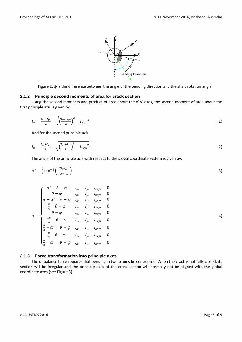
2.1.4 Shear forces and bending moments in the principle planes The shear force and bending moment diagrams for each of the principle axes can be now drawn. As the
support reactions are still unknown they will be represented by pronumerals. The analysis will now consider bending in the plane of second principle axis (V-axis). The same methodology is applied to bending in the plane of the fist principle axis (U-axis). The shear force diagram (SFD) for the V-Z plane is shown below.
Figure 4: Shear force (left) and bending moment (right) diagrams in the plane in of the second principle axis
The bending moment diagram (BMD) for the V-Z plane is obtained by integration of the SFD. The curve of the bending moment diagram is discontinuous due to the influence from the concentrated weight forces and the unbalanced force. Support reaction moments Mau and Mbu are not yet known.
Page 4 of 9 ACOUSTICS 2016
Proceedings of ACOUSTICS 2016 9-11 November 2016, Brisbane, Australia
The bending moment curve shown in Figure 4 has an equation of the form
𝑀𝑀𝑢𝑢(𝑧𝑧) = −1 ×
⎩⎨
⎧𝑚𝑚𝑠𝑠𝑔𝑔𝑣𝑣2𝐿𝐿
𝑧𝑧2 + 𝑅𝑅𝑎𝑎𝑣𝑣𝑧𝑧 + 𝑀𝑀𝑎𝑎𝑢𝑢 0 < 𝑧𝑧 ≤ 𝐿𝐿1𝑚𝑚𝑠𝑠𝑔𝑔𝑣𝑣2𝐿𝐿
𝑧𝑧2 + 𝑚𝑚𝑑𝑑𝑔𝑔𝑣𝑣(𝑧𝑧 − 𝐿𝐿1) + 𝑅𝑅𝑎𝑎𝑣𝑣𝑧𝑧 + 𝑀𝑀𝑎𝑎𝑢𝑢 𝐿𝐿1 < 𝑧𝑧 ≤ 𝐿𝐿2𝑚𝑚𝑠𝑠𝑔𝑔𝑣𝑣2𝐿𝐿
𝑧𝑧2 +𝑚𝑚𝑑𝑑𝑔𝑔𝑣𝑣(2𝑧𝑧 − 𝐿𝐿1 − 𝐿𝐿2) + 𝐹𝐹𝑢𝑢𝑢𝑢𝑣𝑣(𝑧𝑧 − 𝐿𝐿2) + 𝑅𝑅𝑎𝑎𝑣𝑣𝑧𝑧 + 𝑀𝑀𝑎𝑎𝑢𝑢 𝐿𝐿2 < 𝑧𝑧 ≤ 𝐿𝐿
(9)
Note that the equation for the bending moment in the U-Z plane does not have the multiplicative factor of −1 used in equation 9.
2.1.5 Solving for the support reactions By treating the shaft as an Euler beam, the moment area theorem can be applied to solve for the support
reactions. The influence of the crack is accounted for by the reduced second moment of area when integrating the bending moment.
The fixed ends of the shaft mean that displacement and rotation of the shaft at the supports will be zero. The resulting moment area equations will be:
∫ 𝑀𝑀(𝑧𝑧)
𝐸𝐸𝐼𝐼𝑑𝑑𝑧𝑧𝐿𝐿
0 = 0 (10) ∫ 𝑧𝑧 𝑀𝑀𝑢𝑢(𝑧𝑧)
𝐸𝐸𝐼𝐼𝑑𝑑𝑧𝑧𝐿𝐿
0 = 0 (11)
Evaluating both of these integrals yields a system of two simultaneous equations which are solvable for the support reactions using Cramer's rule.
𝑅𝑅𝑎𝑎𝑣𝑣 = �−𝑚𝑚𝑠𝑠𝑔𝑔𝑣𝑣𝑏𝑏1𝑠𝑠−𝑚𝑚𝑑𝑑𝑔𝑔𝑣𝑣𝑏𝑏1𝑑𝑑−𝐹𝐹𝑢𝑢𝑢𝑢𝑣𝑣𝑏𝑏1𝑓𝑓�𝑎𝑎22−�−𝑚𝑚𝑑𝑑𝑔𝑔𝑣𝑣𝑏𝑏2𝑑𝑑−𝐹𝐹𝑢𝑢𝑢𝑢𝑣𝑣𝑏𝑏2𝑓𝑓−𝑚𝑚𝑠𝑠𝑔𝑔𝑣𝑣𝑏𝑏2𝑠𝑠�𝑎𝑎12𝑎𝑎11𝑎𝑎22−𝑎𝑎21𝑎𝑎12
(12)
𝑀𝑀𝑎𝑎𝑢𝑢 = 𝑎𝑎11�−𝑚𝑚𝑑𝑑𝑔𝑔𝑣𝑣𝑏𝑏2𝑑𝑑−𝐹𝐹𝑢𝑢𝑢𝑢𝑣𝑣𝑏𝑏2𝑓𝑓−𝑚𝑚𝑠𝑠𝑔𝑔𝑣𝑣𝑏𝑏2𝑠𝑠�−𝑎𝑎21�−𝑚𝑚𝑠𝑠𝑔𝑔𝑣𝑣𝑏𝑏1𝑠𝑠−𝑚𝑚𝑑𝑑𝑔𝑔𝑣𝑣𝑏𝑏1𝑑𝑑−𝐹𝐹𝑢𝑢𝑢𝑢𝑣𝑣𝑏𝑏1𝑓𝑓�𝑎𝑎11𝑎𝑎22−𝑎𝑎21𝑎𝑎12
(13)
In equations 12 and 13 aij and bij are functions of model geometry and crack breathing state. Their values for cases where the crack is located between the two discs are shown below.
𝑎𝑎11 = 1𝐸𝐸𝐼𝐼�𝐿𝐿
2
2− 𝐿𝐿𝐿𝐿0
𝑢𝑢�+ 1
𝐸𝐸𝐼𝐼𝑢𝑢�𝐿𝐿𝐿𝐿0𝑢𝑢� (14)
𝑎𝑎12 = 1
𝐸𝐸𝐼𝐼�𝐿𝐿 − 𝐿𝐿
𝑢𝑢� + 1
𝐸𝐸𝐼𝐼𝑢𝑢�𝐿𝐿𝑢𝑢� (15)
𝑎𝑎21 = 1𝐸𝐸𝐼𝐼�𝐿𝐿
3
3− 𝐿𝐿3
12𝑢𝑢3− 𝐿𝐿𝐿𝐿02
𝑢𝑢� + 1
𝐸𝐸𝐼𝐼𝑢𝑢� 𝐿𝐿3
12𝑢𝑢3+ 𝐿𝐿𝐿𝐿02
𝑢𝑢� (16)
𝑎𝑎22 = 1𝐸𝐸𝐼𝐼�𝐿𝐿
2
2− 𝐿𝐿𝐿𝐿0
𝑢𝑢� + 1
𝐸𝐸𝐼𝐼𝑢𝑢�𝐿𝐿𝐿𝐿0𝑢𝑢� (17)
𝑏𝑏1𝑠𝑠 = 1𝐸𝐸𝐼𝐼�𝐿𝐿
2
6− 𝐿𝐿2
24𝑢𝑢3− 𝐿𝐿02
2𝑢𝑢� + 1
𝐸𝐸𝐼𝐼𝑢𝑢� 𝐿𝐿2
24𝑢𝑢3+ 𝐿𝐿02
2𝑢𝑢� (18)
𝑏𝑏1𝑑𝑑 = 1𝐸𝐸𝐼𝐼�𝐿𝐿2 + 𝐿𝐿12
2+ 𝐿𝐿22
2− 𝐿𝐿𝐿𝐿1 − 𝐿𝐿𝐿𝐿2 −
𝐿𝐿𝐿𝐿0𝑢𝑢
+ 𝐿𝐿𝐿𝐿1𝑢𝑢�+ 1
𝐸𝐸𝐼𝐼𝑢𝑢�𝐿𝐿𝐿𝐿0𝑢𝑢− 𝐿𝐿𝐿𝐿1
𝑢𝑢� (19)
𝑏𝑏1𝑓𝑓 = 1𝐸𝐸𝐼𝐼�𝐿𝐿
2
2− 𝐿𝐿𝐿𝐿2 + 𝐿𝐿22
2� (20)
ACOUSTICS 2016 Page 5 of 9

9-11 November 2016, Brisbane, Australia Proceedings of ACOUSTICS 2016
𝑏𝑏2𝑠𝑠 = 1𝐸𝐸𝐼𝐼�𝐿𝐿
3
8− 𝐿𝐿03
2𝑢𝑢− 𝐿𝐿2𝐿𝐿0
8𝑢𝑢3�+ 1
𝐸𝐸𝐼𝐼𝑢𝑢�𝐿𝐿0
3
2𝑢𝑢+ 𝐿𝐿2𝐿𝐿0
8𝑢𝑢3� (21)
𝑏𝑏2𝑑𝑑 = 1𝐸𝐸𝐼𝐼�2𝐿𝐿
3
3− 𝐿𝐿2𝐿𝐿2
2− 𝐿𝐿2𝐿𝐿1
2+ 𝐿𝐿13
6+ 𝐿𝐿23
6− 𝐿𝐿3
12𝑢𝑢3− 𝐿𝐿𝐿𝐿02
𝑢𝑢+ 𝐿𝐿𝐿𝐿0𝐿𝐿1
𝑢𝑢�+ 1
𝐸𝐸𝐼𝐼𝑢𝑢� 𝐿𝐿3
12𝑢𝑢3+ 𝐿𝐿𝐿𝐿02
𝑢𝑢− 𝐿𝐿𝐿𝐿0𝐿𝐿1
𝑢𝑢� (22)
𝑏𝑏2𝑓𝑓 = 1𝐸𝐸𝐼𝐼�𝐿𝐿
3
3− 𝐿𝐿2𝐿𝐿2
2+ 𝐿𝐿23
6� (23)
The support reactions in the plane of the first principle axis can be calculated by substituting the 2nd moment
of area and transformed loads for that plane into equations 12 – 23.
2.1.6 Evaluating the bending moment at the crack location The components of the bending moment at the crack location in principle coordinates are given below. Note
the difference in the signs of the terms, which is simply a property of the coordinate system chosen. 𝑀𝑀𝑢𝑢(𝐿𝐿0) = −𝑚𝑚𝑠𝑠𝑔𝑔𝑣𝑣
2𝐿𝐿𝐿𝐿02 − (𝑅𝑅𝑎𝑎𝑣𝑣 + 𝑚𝑚𝑑𝑑𝑔𝑔𝑣𝑣)𝐿𝐿0 −𝑀𝑀𝑎𝑎𝑢𝑢 + 𝑚𝑚𝑑𝑑𝑔𝑔𝑣𝑣𝐿𝐿1 (24)
𝑀𝑀𝑣𝑣(𝐿𝐿0) = 𝑚𝑚𝑠𝑠𝑔𝑔𝑢𝑢
2𝐿𝐿𝐿𝐿02 + (𝑅𝑅𝑎𝑎𝑢𝑢 + 𝑚𝑚𝑑𝑑𝑔𝑔𝑢𝑢)𝐿𝐿0 +𝑀𝑀𝑎𝑎𝑣𝑣 −𝑚𝑚𝑑𝑑𝑔𝑔𝑢𝑢𝐿𝐿1 (25)
With the bending moments about both principle axes known, the direction of the bending moment needs to
be evaluated. An angle ѱ is defined at the angle between the bending moment vector and the positive direction of the first principle axis (U-axis). The range of ѱ is restricted to 0 < ѱ < 2𝜋𝜋 with anticlockwise rotation being positive. It is evaluated below
𝜓𝜓∗ = tan−1 ��𝑀𝑀𝑣𝑣(𝐿𝐿0)𝑀𝑀𝑢𝑢(𝐿𝐿0)�� (26)
𝜓𝜓 =
⎩⎨
⎧𝜓𝜓∗ 𝑀𝑀𝑢𝑢(𝐿𝐿0) > 0 𝑀𝑀𝑣𝑣(𝐿𝐿0) ≥ 0
2𝜋𝜋 − 𝜓𝜓∗ 𝑀𝑀𝑢𝑢(𝐿𝐿0) > 0 𝑀𝑀𝑣𝑣(𝐿𝐿0) < 0𝜋𝜋 − 𝜓𝜓∗ 𝑀𝑀𝑢𝑢(𝐿𝐿0) < 0 𝑀𝑀𝑣𝑣(𝐿𝐿0) ≥ 0𝜋𝜋 + 𝜓𝜓∗ 𝑀𝑀𝑢𝑢(𝐿𝐿0) < 0 𝑀𝑀𝑣𝑣(𝐿𝐿0) < 0
(27)
2.1.7 Effective bending angle In this model it is assumed that the neutral axis of the crack section is parallel to the bending moment vector.
The crack's breathing state is a function of orientation of the neutral plane, the bending direction and the shaft's rotation angle. At this point it is worth considering the relationship between these vectors with the aid of a diagram of the crack section. Both the global and principle coordinate axes are shown in the diagram below.
From Figure 3, it is apparent that φ is a function of the shaft rotation angle θ, the angle between the principle axes and the global axes α, and the angle between the bending moment vector and the first principle axis ψ.
𝜑𝜑 = 𝜋𝜋 + 𝜃𝜃 − 𝛼𝛼 − 𝜓𝜓 (28)
Equation 28 will give an estimate for the value of ϕ that will be more accurate than either the initial guessed value or the value obtained from any subsequent iterations. Each repetition of the process, described above, will yield a more accurate value for φ. Because of the interdependence between φ, the shaft stiffness, bending moments and deflection, the accuracy of these variables is also improved. For practical purposes, convergence is typically achieved within 4 iterations regardless of the initial guess value for φ.
3. RESULTS FOR BREATHING RESPONSE The breathing response of the model has been evaluated for a set of model parameters that are outlined in Table 1. The breathing state can be completely described by effective bending angle φ and qualitatively understood by the crack opening state. Both variables have been evaluated and are presented.
Page 6 of 9 ACOUSTICS 2016

Proceedings of ACOUSTICS 2016 9-11 November 2016, Brisbane, Australia
Table 1: List of parameters used to evaluated the breathing response
Parameter Value Parameter Value
Shaft length, L (m) 0.725 Disc 2 location, L2 (m) 0.543
Shaft radius, R (m) 0.00635 Reduce section proportion, n 100
Shaft Young's modulus, E (GPa) 210 Relative crack location, λ Varied
Shaft density, ρ (kg/m3) 7800 Relative crack depth, μ 0.75
Disc mass (both discs), md (kg) 0.5 Unbalance force ratio, η 10
Disc 1 location, L1 (m) 0.181 Unbalance force phase, 𝛽𝛽 (°) 90
The evaluation of the breathing response is performed using the following parameter definitions for mass unbalance force, Fun, crack depth, h and crack location, L0:
𝜂𝜂 = 𝑚𝑚𝑠𝑠𝑔𝑔+2𝑚𝑚𝑑𝑑𝑔𝑔
𝐹𝐹𝑢𝑢𝑢𝑢 (29)
𝜇𝜇 = ℎ
𝑅𝑅= 2ℎ
𝐷𝐷 (30)
𝜆𝜆 = 𝐿𝐿0
𝐿𝐿 (31)
The effective breathing angle for several shaft rotation angles has been evaluated for every possible crack
location (i.e. from λ=0 to λ=1) using the presented algorithm. The results are presented in Figure 5. Note that terms φ1, φ2, φ3 & φ4 shown in Figure 5 are the effective bending angles at which the crack starts to close, becomes fully closed, starts to reopen and is fully open again respectively. Their values are dependent on the crack depth and are calculated using equations derived by Al-Shudeifat and Butcher (2011).
Figure 5: Effective bending angle throughout the shaft length for rotation angles of 0°, 60° and 120°. Model
parameters are: β=90°, µ=0.75 and η=10
ACOUSTICS 2016 Page 7 of 9
9-11 November 2016, Brisbane, Australia Proceedings of ACOUSTICS 2016 The apparent discontinuities in Figure 5 near λ=0.2 and λ=0.8 are simply the result restricting the numerical
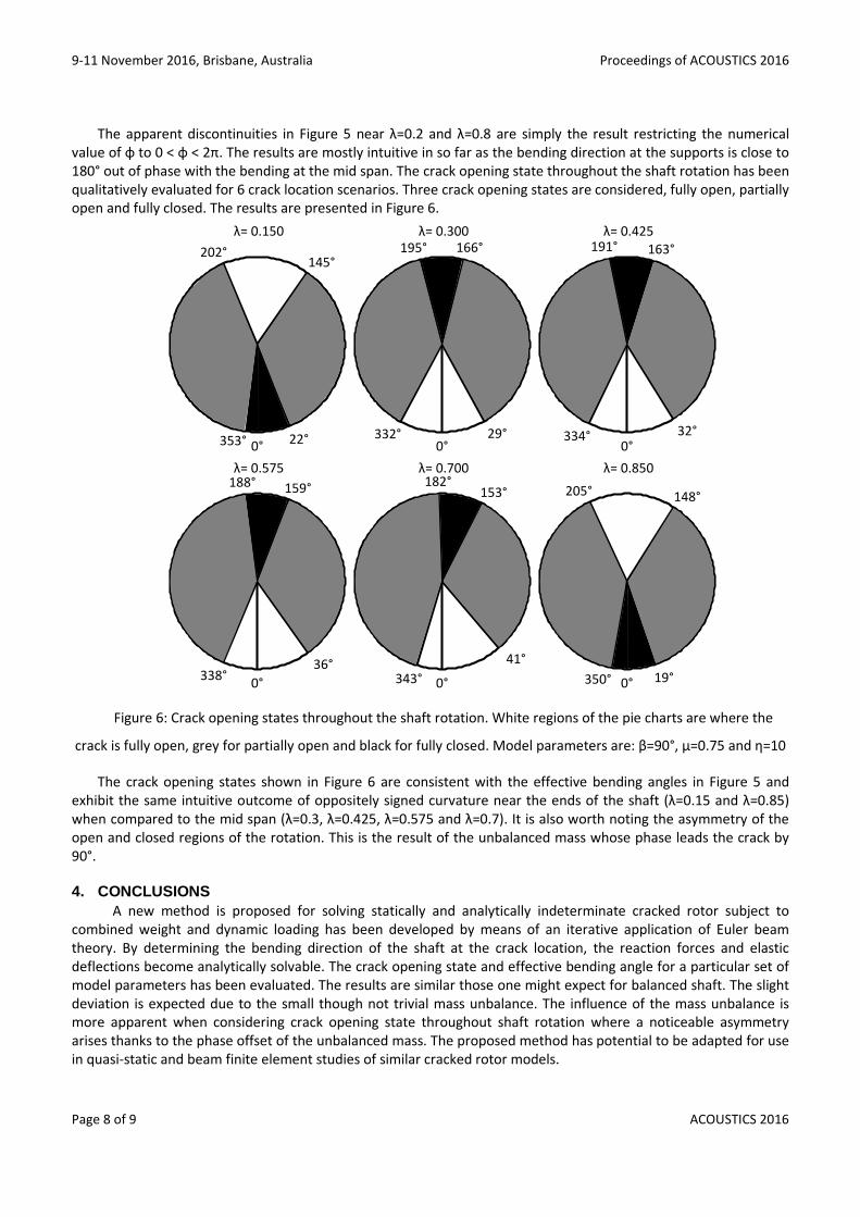
value of φ to 0 < φ < 2π. The results are mostly intuitive in so far as the bending direction at the supports is close to 180° out of phase with the bending at the mid span. The crack opening state throughout the shaft rotation has been qualitatively evaluated for 6 crack location scenarios. Three crack opening states are considered, fully open, partially open and fully closed. The results are presented in Figure 6.
Figure 6: Crack opening states throughout the shaft rotation. White regions of the pie charts are where the
crack is fully open, grey for partially open and black for fully closed. Model parameters are: β=90°, µ=0.75 and η=10
The crack opening states shown in Figure 6 are consistent with the effective bending angles in Figure 5 and exhibit the same intuitive outcome of oppositely signed curvature near the ends of the shaft (λ=0.15 and λ=0.85) when compared to the mid span (λ=0.3, λ=0.425, λ=0.575 and λ=0.7). It is also worth noting the asymmetry of the open and closed regions of the rotation. This is the result of the unbalanced mass whose phase leads the crack by 90°.
4. CONCLUSIONS A new method is proposed for solving statically and analytically indeterminate cracked rotor subject to
combined weight and dynamic loading has been developed by means of an iterative application of Euler beam theory. By determining the bending direction of the shaft at the crack location, the reaction forces and elastic deflections become analytically solvable. The crack opening state and effective bending angle for a particular set of model parameters has been evaluated. The results are similar those one might expect for balanced shaft. The slight deviation is expected due to the small though not trivial mass unbalance. The influence of the mass unbalance is more apparent when considering crack opening state throughout shaft rotation where a noticeable asymmetry arises thanks to the phase offset of the unbalanced mass. The proposed method has potential to be adapted for use in quasi-static and beam finite element studies of similar cracked rotor models.
Page 8 of 9 ACOUSTICS 2016
Proceedings of ACOUSTICS 2016 9-11 November 2016, Brisbane, Australia
ACKNOWLEDGEMENTS The authors wish to thank Dr Keqin Xiao for his continued guidance and insight throughout this research.
REFERENCES AL-SHUDEIFAT, M. A. & BUTCHER, E. A. 2011. New breathing functions for the transverse breathing crack of the cracked
rotor system: Approach for critical and subcritical harmonic analysis. Journal of Sound and Vibration, 330, 526-544.
BACHSCHMID, N. & TANZI, E. 2004. Deflections and strains in cracked shafts due to rotating loads: a numerical and experimental analysis. International Journal of Rotating Machinery, 10, 283-291.
GUO, C., AL-SHUDEIFAT, M., YAN, J., BERGMAN, L., MCFARLAND, D. & BUTCHER, E. 2013. Application of empirical mode decomposition to a Jeffcott rotor with a breathing crack. Journal of Sound and Vibration, 332, 3881-3892.
RUBIO, L., MUÑOZ-ABELLA, B. & LOAIZA, G. 2011. Static behaviour of a shaft with an elliptical crack. Mechanical Systems and Signal Processing, 25, 1674-1686.
RUBIO, L., MUÑOZ-ABELLA, B., RUBIO, P. & MONTERO, L. 2014. Quasi-static numerical study of the breathing mechanism of an elliptical crack in an unbalanced rotating shaft. Latin American Journal of Solids & Structures, 11, 2333-2350.
SPAGNOL, J. P. & WU, H. Breathing mechanism of a cracked rotor subject to non-trivial mass unbalance. INTER-NOISE and NOISE-CON Congress and Conference Proceedings, 2014. Institute of Noise Control Engineering, 6404-6410.
ACOUSTICS 2016 Page 9 of 9
Related Documents