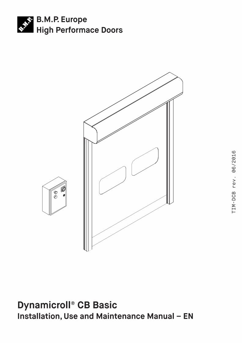
TIM-DCB rev. 06/2016 B.M.P. Europe High Performace Doors Dynamicroll® CB Basic Installation, Use and Maintenance Manual – EN

Welcome message from author
This document is posted to help you gain knowledge. Please leave a comment to let me know what you think about it! Share it to your friends and learn new things together.
Transcript
TIM-DCB r
ev. 0
6/2016
B.M.P. EuropeHigh Performace Doors
Dynamicroll® CB BasicInstallation, Use and Maintenance Manual – EN
TIM-DCB rev. 06/2016 2B.M.P. Europe
1 Safetyprecautions 22 Technicalfeatures 33 MechanicalInstallation 44 Electricdiagram–Componentslayout 65 Controlunit 75.1 Connectionstosupplyandautomation 75.2 Connectionstocommandsandsafetydevices 85.3 ManualJoganddisplay 95.4 Positionandclosingtimeadjustmentwithencoder 105.5 Positionandclosingtimeadjustmentwithlimitswitches 115.6 Pedestrianopeningadjustment 125.7 Interlock 126 Safetydevices 137 Useinstruction 148 Maintenanceinstruction 159 Alarmslist 1610 Runningoptionslist 17
1 General Safety precautions
Thismanual is aimed exclusively at installers and techni-ciansprofessionallycompetent.Alloperationsofmechanicalinstallation,electricalconnectionsandadjustmentsmustbemaderespectingthegoodworkmanshipandapplyingallthesafetyruleinforce,eveniftheirindicationswerenotexplicitinthetextoftheinstructions.
Beforestartingtheinstallationofthedoorreadthein-structionscarefully.Incorrectinstallationcanbedangerous.Beforebeginningtheinstallationcheckperfectconditionoftheproduct.
Before installing the door, Ensure that the floor, thewallsortheexistingsupportstructurehavethenecessarystrength,capableofsupportingtheweightofthedoor,alsoconsideringthedynamicforcesduetonormaloperationandtheeventualimpacts.Ifnecessarymakemodificationtothestructuresbeforethedoorinstallation.Verifythatthestruc-tureissuitabletoprotectorisolatealltheareasaffectedbythedangerofcrushing,trimming,trappingandgeneraldan-ger.
Automationisequippedwiththenecessarysafetyde-vicestoensurecompliancewithproductstandards.Thesedevices (photocells, safety edges, emergency stop, etc.)Mustbeconnectedaccordingtocurrentregulationsanddi-rectivesinforce,goodworkmanshipcriteria,theinstallationenvironment, theoperating logicof thesystemand forcesdevelopedbythedoor.Displaythesignsrequiredbylawtoidentify danger areas. Each installationmust clearly showtheidentificationdataofthedoor.
Before connecting the power supply, check that thedataon the labelcorrespond to theelectricitydistributionnetwork.Amainspowerswitchproperlysizedmustbe in-stalledbeforethecontrolboardinlet.Checkthatthepower
line is protectedbyRCD and overcurrent protection.Con-nectthedoortoanefficientgroundingsystem.
Themanufacturerofthedoordeclinesallresponsibili-tyifcomponentswhichareincompatiblewiththesafeandcorrect operation or when changes aremade of any kindwithout the specific permission of themanufacturer. Onlyoriginalsparepartsshallbeusedforrepairsorreplacementofcomponentsduringmaintenanceorservice.
Theinstallermustsupplyallinformationrelatingtoau-tomationconcerningmanualandemergencyoperationsandprovidetheusertheInstructionsforUse.
After installation, packaging materials (plastic, card-board,etc.)mustnotbeallowedtolittertheenvironment.
This document was issued by theManufacturer withtheutmostcare,inanycasetheManufacturerdoesnotacceptresponsibilityforanydamagecausedbyerrorsoromissionsinthispublication.Wereservetherighttochangethecontentswithoutnotice.Norightscanbederivedfromthecontentsof thisdocument. It ispro-hibitedtocopyorotherwisepublishbyanymeanswith-outwrittenpermissionofthemanufacturer.Allrightsreserved.
TIM-DCB rev. 06/2016 3B.M.P. Europe
2 Installation drawing and technical features
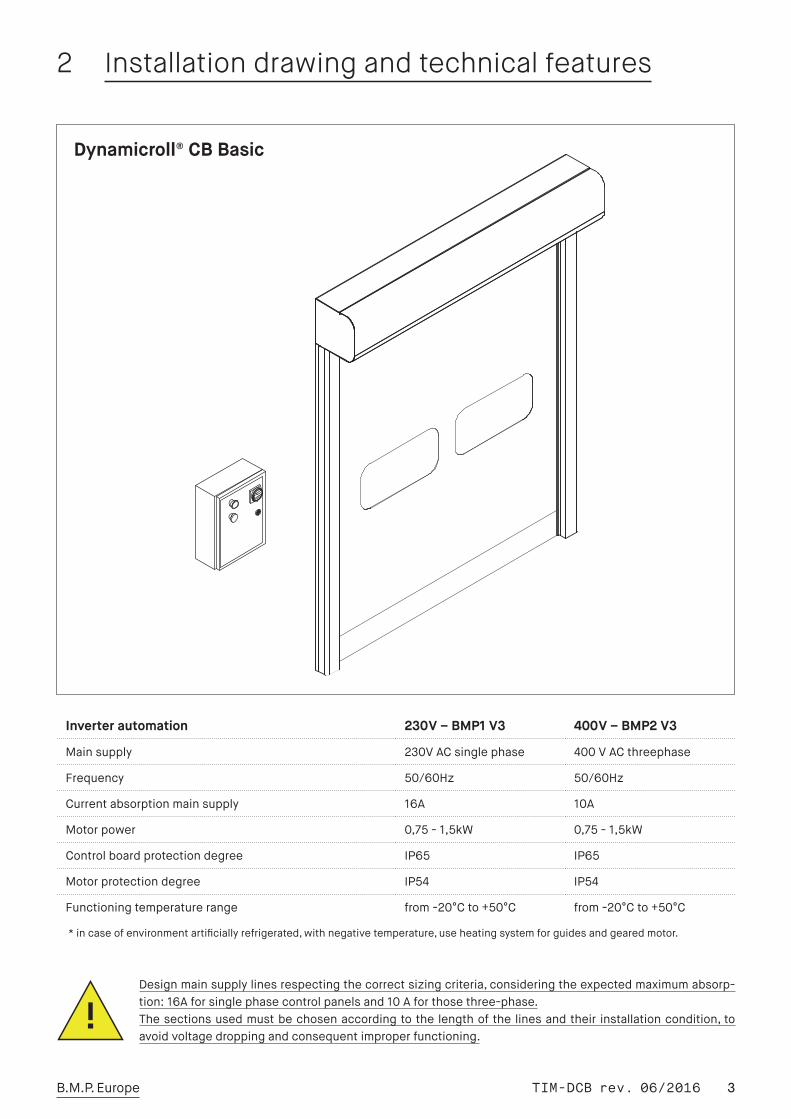
Designmainsupplylinesrespectingthecorrectsizingcriteria,consideringtheexpectedmaximumabsorp-tion:16Aforsinglephasecontrolpanelsand10Aforthosethree-phase.Thesectionsusedmustbechosenaccordingtothelengthofthelinesandtheir installationcondition,toavoidvoltagedroppingandconsequentimproperfunctioning.
Dynamicroll® CB Basic
Inverter automation 230 V – BMP1 V3 400 V – BMP2 V3
Mainsupply 230VACsinglephase 400VACthreephase
Frequency 50/60Hz 50/60Hz
Currentabsorptionmainsupply 16A 10A
Motorpower 0,75-1,5kW 0,75-1,5kW
Controlboardprotectiondegree IP65 IP65
Motorprotectiondegree IP54 IP54
Functioningtemperaturerange from-20°Cto+50°C from-20°Cto+50°C
*incaseofenvironmentartificiallyrefrigerated,withnegativetemperature,useheatingsystemforguidesandgearedmotor.
TIM-DCB rev. 06/2016 4B.M.P. Europe
3 Mechanical installation
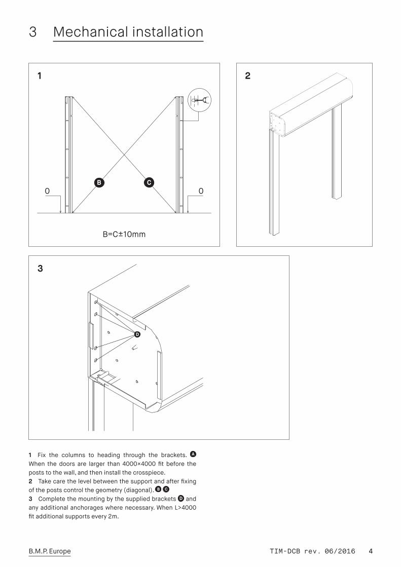
1 Fix the columns to heading through the brackets. When the doors are larger than 4000×4000 fit before thepoststothewall,andtheninstallthecrosspiece.2 Takecarethelevelbetweenthesupportandafterfixingofthepostscontrolthegeometry(diagonal). 3 Completethemountingbythesuppliedbrackets D andanyadditionalanchorageswherenecessary.WhenL>4000fitadditionalsupportsevery2m.
1
3
2
D
TIM-DCB rev. 06/2016 5B.M.P. Europe
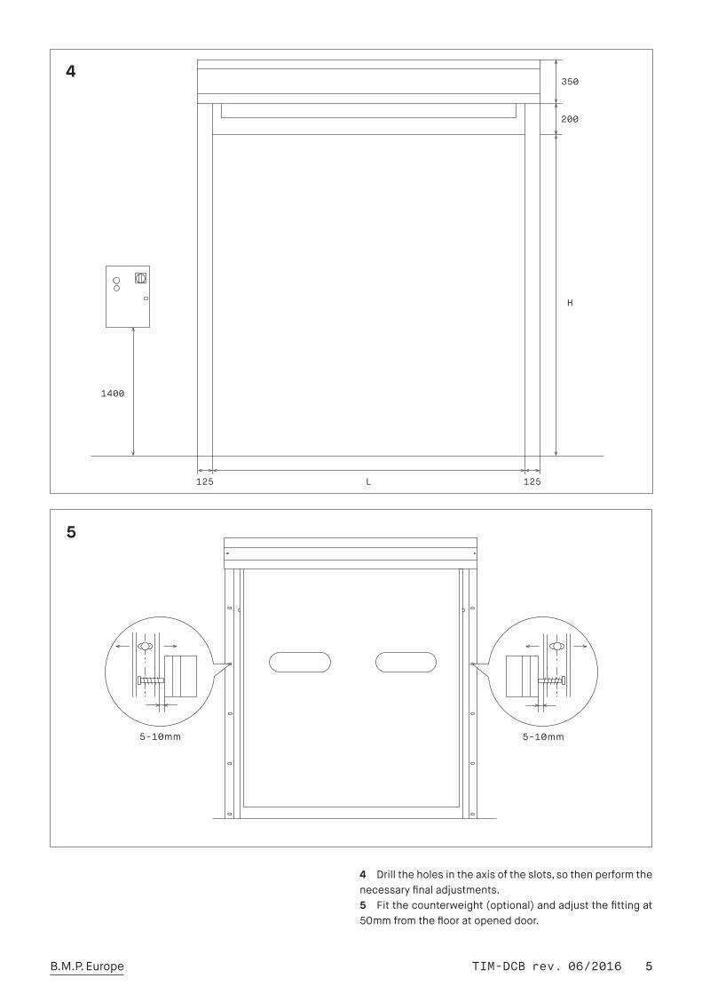
4 Drilltheholesintheaxisoftheslots,sothenperformthenecessaryfinaladjustments.5 Fitthecounterweight(optional)andadjustthefittingat50mmfromtheflooratopeneddoor.
4
5
TIM-DCB rev. 06/2016 6B.M.P. Europe
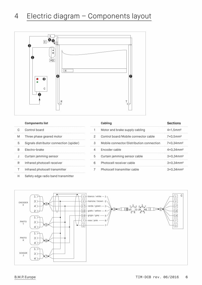
4 Electric diagram – Components layout
Components list
C Controlboard
M Threephasegearedmotor
S Signalsdistributorconnection(spider)
B Electro-brake
J Curtainjammingsensor
R Infraredphotocellreceiver
T Infraredphotocelltransmitter
H Safetyedgeradiobandtransmitter
Cabling Sections
1 Motorandbrakesupplycabling 4×1,5mm2
2 Controlboard/Mobileconnectorcable 7×0,5mm2
3 Mobileconnector/Distributionconnection 7×0,34mm2
4 Encodercable 4×0,34mm2
5 Curtainjammingsensorcable 3×0,34mm2
6 Photocellreceivercable 3×0,34mm2
7 Photocelltransmittercable 3×0,34mm2
TIM-DCB rev. 06/2016 7B.M.P. Europe
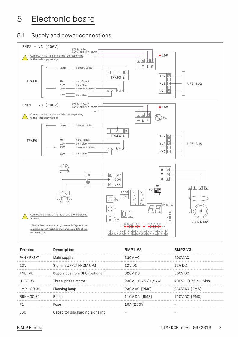
5 Electronic board
5.1 Supply and power connections
Terminal Description BMP1 V3 BMP2 V3
P-N/R-S-T Mainsupply 230VAC 400VAC
12V SignalSUPPLYFROMUPS 12VDC 12VDC
+VB-VB SupplybusfromUPS(optional) 320VDC 560VDC
U-V-W Three-phasemotor 230V–0,75/1,5kW 400V–0,75/1,5kW
LMP-2930 Flashinglamp 230VAC [RMS] 230VAC [RMS]
BRK-3031 Brake 110VDC [RMS] 110VDC [RMS]
F1 Fuse 10A(230V) –
LD0 Capacitordischargingsignaling – –
BMP2 – V3 (400V)
BMP1 – V3 (230V)
Connecttheshieldofthemotorcabletothegroundterminal.
*Verifythatthemotorprogrammedin"systempa-rameterssetup"matchesthenameplatedataoftheinstalledtype.
Connecttothetransformerinletcorrespondingtotherealsupplyvoltage
Connecttothetransformerinletcorrespondingtotherealsupplyvoltage
TIM-DCB rev. 06/2016 8B.M.P. Europe
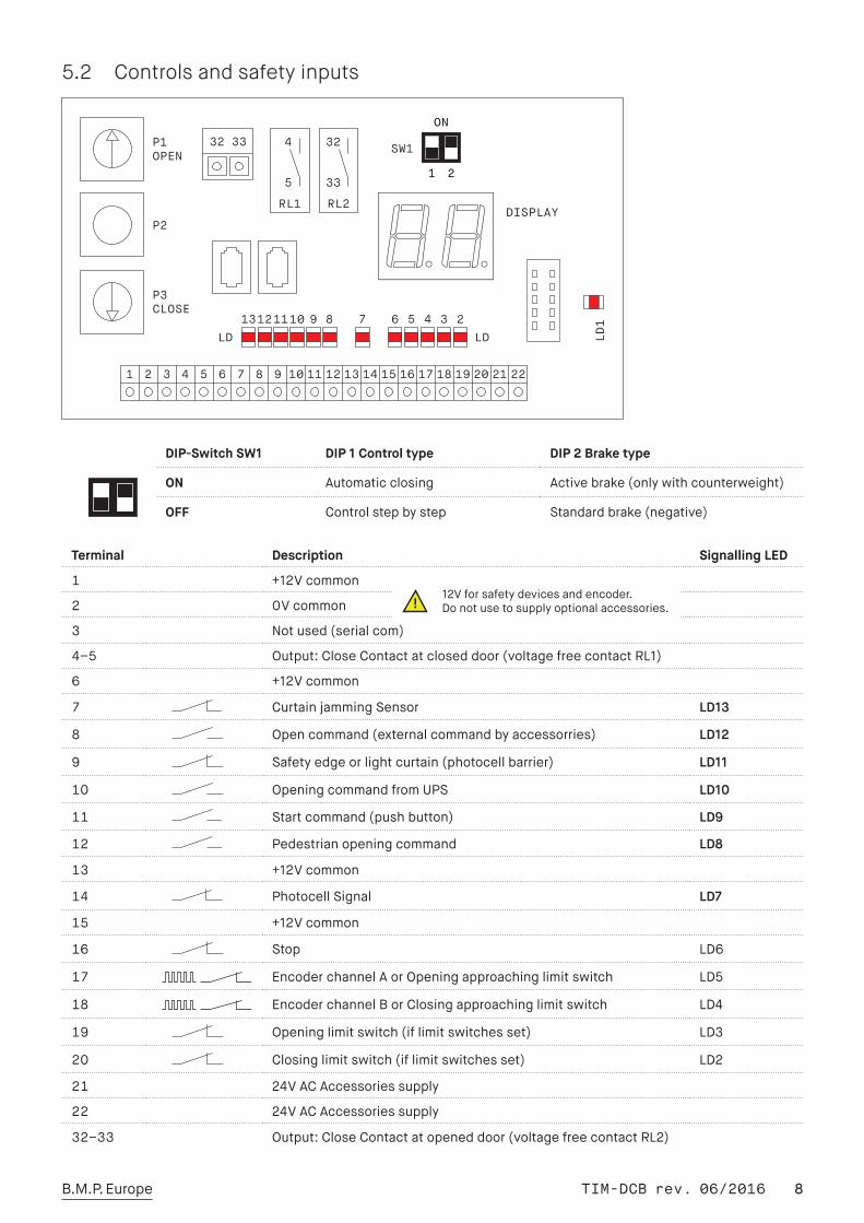
Terminal Description Signalling LED
1 +12Vcommon
2 0Vcommon
3 Notused(serialcom)
4–5 Output:CloseContactatcloseddoor(voltagefreecontactRL1)
6 +12Vcommon
7 CurtainjammingSensor LD13
8 Opencommand(externalcommandbyaccessorries) LD12
9 Safetyedgeorlightcurtain(photocellbarrier) LD11
10 OpeningcommandfromUPS LD10
11 Startcommand(pushbutton) LD9
12 Pedestrianopeningcommand LD8
13 +12Vcommon
14 PhotocellSignal LD7
15 +12Vcommon
16 Stop LD6
17 EncoderchannelAorOpeningapproachinglimitswitch LD5
18 EncoderchannelBorClosingapproachinglimitswitch LD4
19 Openinglimitswitch(iflimitswitchesset) LD3
20 Closinglimitswitch(iflimitswitchesset) LD2
21 24VACAccessoriessupply
22 24VACAccessoriessupply
32–33 Output:CloseContactatopeneddoor(voltagefreecontactRL2)
DIP-Switch SW1 DIP 1 Control type DIP 2 Brake type
ON Automaticclosing Activebrake(onlywithcounterweight)
OFF Controlstepbystep Standardbrake(negative)
5.2 Controls and safety inputs
12Vforsafetydevicesandencoder.Donotusetosupplyoptionalaccessories.
TIM-DCB rev. 06/2016 9B.M.P. Europe
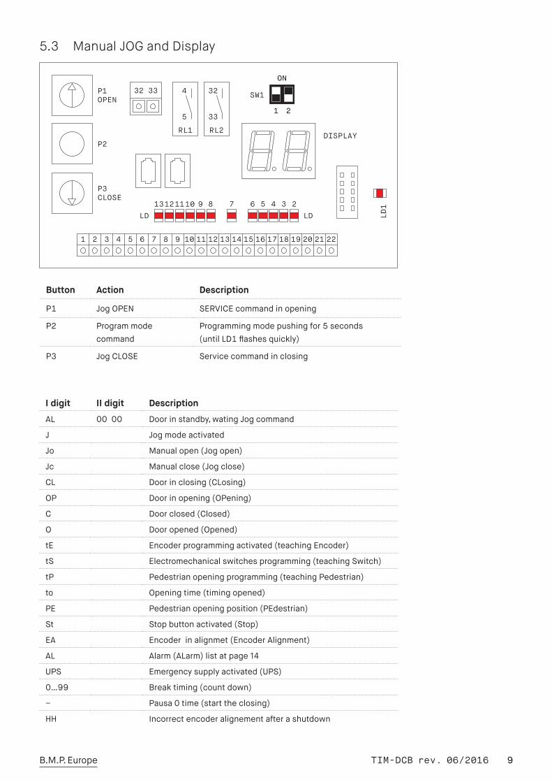
5.3 Manual JOG and Display
Button Action Description
P1 JogOPEN SERVICEcommandinopening
P2 Programmodecommand
Programmingmodepushingfor5seconds(untilLD1flashesquickly)
P3 JogCLOSE Servicecommandinclosing
I digit II digit Description
AL 00 00 Doorinstandby,watingJogcommand
J Jogmodeactivated
Jo Manualopen(Jogopen)
Jc Manualclose(Jogclose)
CL Doorinclosing(CLosing)
OP Doorinopening(OPening)
C Doorclosed(Closed)
O Dooropened(Opened)
tE Encoderprogrammingactivated(teachingEncoder)
tS Electromechanicalswitchesprogramming(teachingSwitch)
tP Pedestrianopeningprogramming(teachingPedestrian)
to Openingtime(timingopened)
PE Pedestrianopeningposition(PEdestrian)
St Stopbuttonactivated(Stop)
EA Encoderinalignmet(EncoderAlignment)
AL Alarm(ALarm)listatpage14
UPS Emergencysupplyactivated(UPS)
0…99 Breaktiming(countdown)
– Pausa0time(starttheclosing)
HH Incorrectencoderalignementafterashutdown
TIM-DCB rev. 06/2016 10B.M.P. Europe
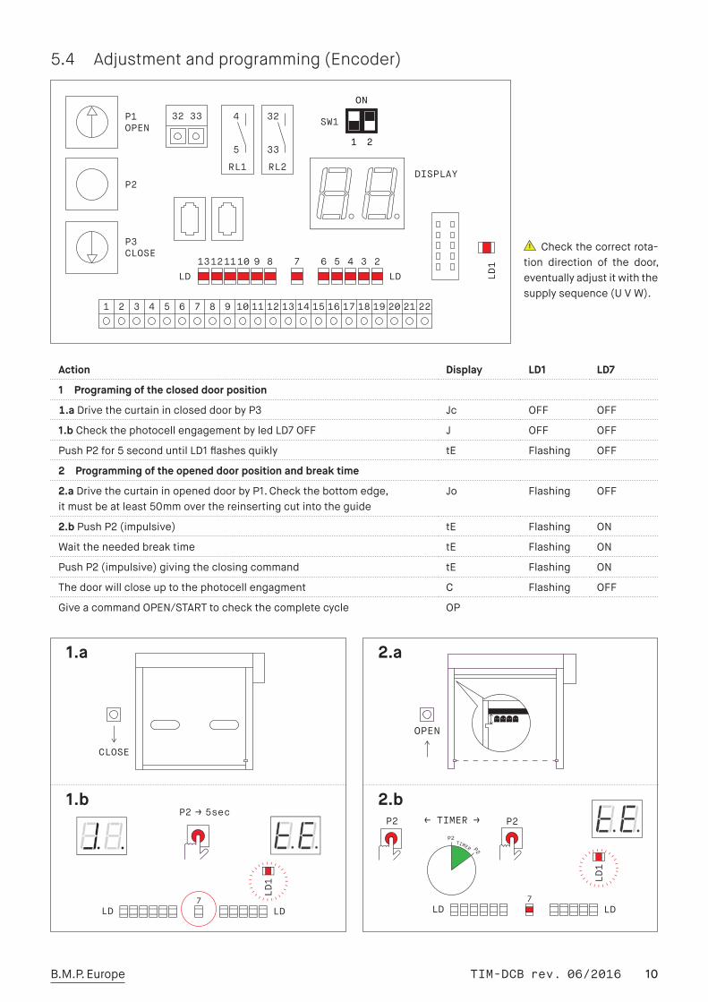
5.4 Adjustment and programming (Encoder)
Checkthecorrectrota-tion direction of the door,eventuallyadjustitwiththesupplysequence(UVW).
Action Display LD1 LD7
1 Programing of the closed door position
1.a DrivethecurtainincloseddoorbyP3 Jc OFF OFF
1.b CheckthephotocellengagementbyledLD7OFF J OFF OFF
PushP2for5seconduntilLD1flashesquikly tE Flashing OFF
2 Programming of the opened door position and break time
2.a DrivethecurtaininopeneddoorbyP1.Checkthebottomedge,itmustbeatleast50mmoverthereinsertingcutintotheguide
Jo Flashing OFF
2.b PushP2(impulsive) tE Flashing ON
Waittheneededbreaktime tE Flashing ON
PushP2(impulsive)givingtheclosingcommand tE Flashing ON
Thedoorwillcloseuptothephotocellengagment C Flashing OFF
GiveacommandOPEN/STARTtocheckthecompletecycle OP
1.a 2.a
1.b 2.b
OPEN����
TIM-DCB rev. 06/2016 11B.M.P. Europe
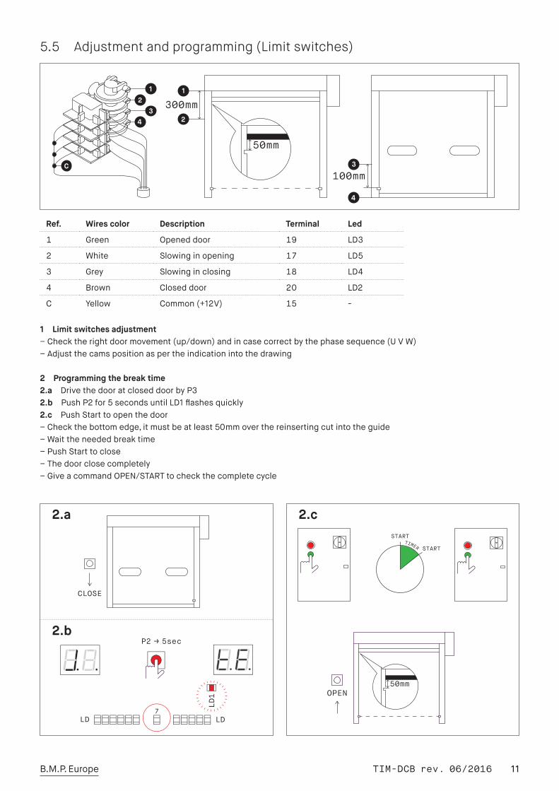
5.5 Adjustment and programming (Limit switches)
1 Limit switches adjustment–Checktherightdoormovement(up/down)andincasecorrectbythephasesequence(UVW)–Adjustthecamspositionaspertheindicationintothedrawing
2 Programming the break time2.a DrivethedooratcloseddoorbyP32.b PushP2for5secondsuntilLD1flashesquickly2.c PushStarttoopenthedoor–Checkthebottomedge,itmustbeatleast50mmoverthereinsertingcutintotheguide–Waittheneededbreaktime–PushStarttoclose–Thedoorclosecompletely–GiveacommandOPEN/STARTtocheckthecompletecycle
Ref. Wires color Description Terminal Led
1 Green Openeddoor 19 LD3
2 White Slowinginopening 17 LD5
3 Grey Slowinginclosing 18 LD4
4 Brown Closeddoor 20 LD2
C Yellow Common(+12V) 15 -
START
START TIMER
2.a 2.c
2.b
TIM-DCB rev. 06/2016 12B.M.P. Europe
5.6 Pedestrian opening ajustment
A Pedestrian opening with Encoder system–Connectthepedestriancommandbetweentheterminals13-12–DrivethedoorincloseddoorpositionbyP3–OpenthedoorbyP1uptotheneededpedestrianpassageposition–Starttheprogramming,pushingP2for5s(LD1flashesquickly)–Giveacommandforpedestrianopening(13-12)–Waittheneededbreaktime–GiveacommandforpedestrianpasSage(13-12)tosavethetiming
B Pedestrian opening with limit switches system–Connectthepedestriancommandbetweentheterminals13-12–DrivethedoorincloseddoorpositionbyP1–StarttheprogrammingpusingP2for5s(LD2flashesquickly)–OpenthedoorbyP1uptotheneededpedestrianpassageposition–Giveacommandforpedestrianopening(13-12)–Attheneededpositiongiveapedestrianopeningcommand(13-12)–Waittheneededbreaktime-Giveacommandforpedestrianpassage(13-12)tosavethetiming
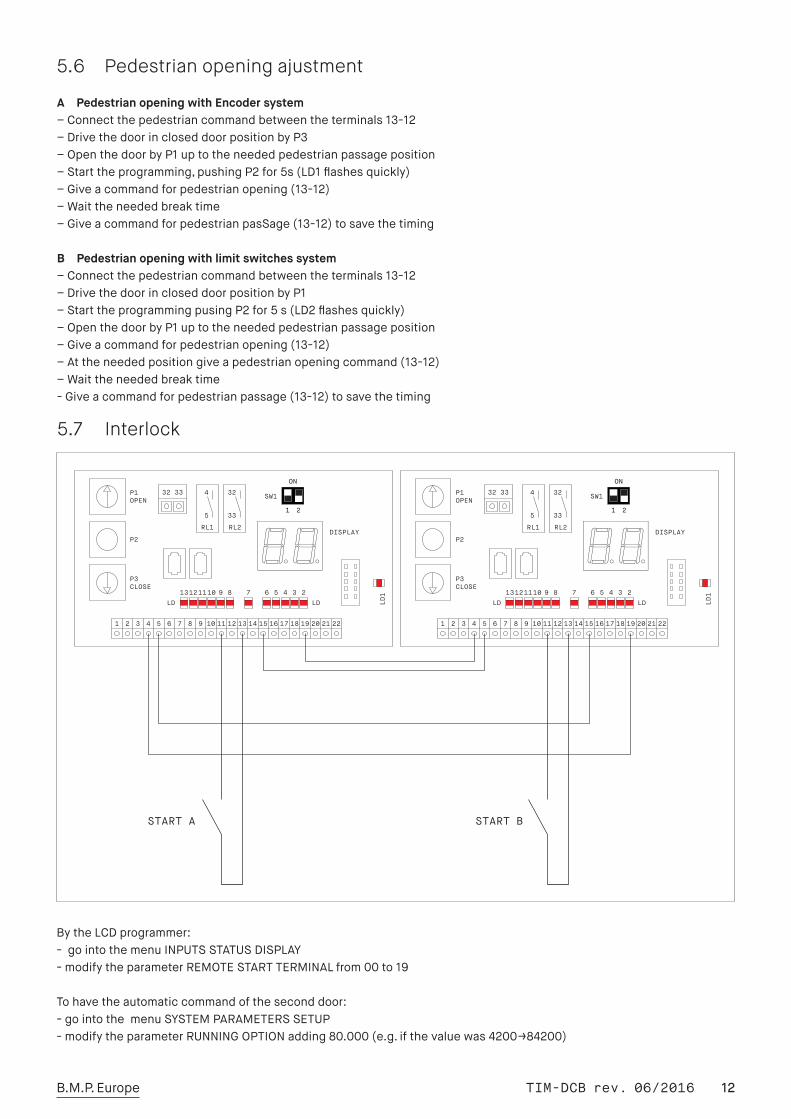
5.7 Interlock
BytheLCDprogrammer:-gointothemenuINPUTSSTATUSDISPLAY-modifytheparameterREMOTESTARTTERMINALfrom00to19
Tohavetheautomaticcommandoftheseconddoor:-gointothemenuSYSTEMPARAMETERSSETUP-modifytheparameterRUNNINGOPTIONadding80.000(e.g.ifthevaluewas4200→84200)
TIM-DCB rev. 06/2016 13B.M.P. Europe
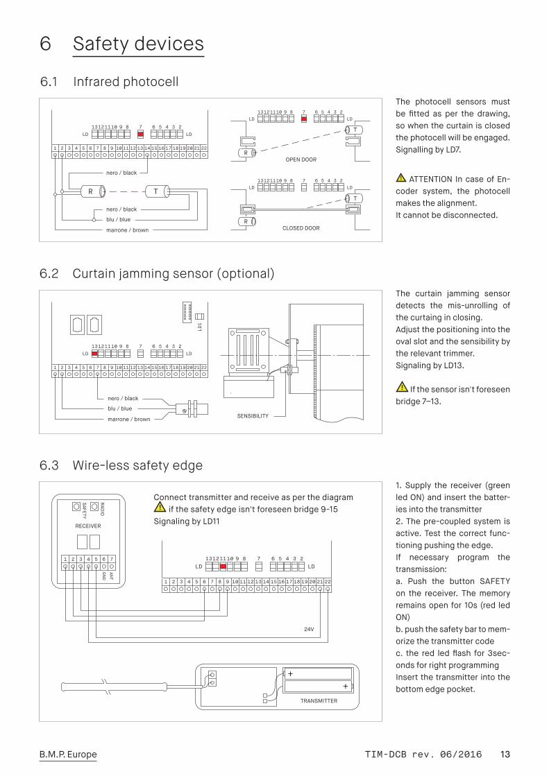
6 Safety devices
6.1 Infrared photocell
6.2 Curtain jamming sensor (optional)
6.3 Wire-less safety edge
The curtain jamming sensordetects the mis-unrolling ofthecurtainginclosing.Adjustthepositioningintotheovalslotandthesensibilitybytherelevanttrimmer.SignalingbyLD13.
Ifthesensorisn'tforeseenbridge7–13.
1. Supply the receiver (greenledON)andinsertthebatter-iesintothetransmitter2.Thepre-coupledsystem isactive.Test thecorrect func-tioningpushingtheedge.If necessary program thetransmission:a. Push the button SAFETYon the receiver. Thememoryremainsopenfor10s(red ledON)b.pushthesafetybartomem-orizethetransmittercodec. the red led flash for 3sec-ondsforrightprogrammingInsertthetransmitterintothebottomedgepocket.
The photocell sensors mustbe fitted as per the drawing,sowhenthecurtainisclosedthephotocellwillbeengaged.SignallingbyLD7.
ATTENTION IncaseofEn-coder system, the photocellmakesthealignment.Itcannotbedisconnected.
Connecttransmitterandreceiveasperthediagramifthesafetyedgeisn'tforeseenbridge9-15
SignalingbyLD11
TIM-DCB rev. 06/2016 14B.M.P. Europe
7 Use instructions
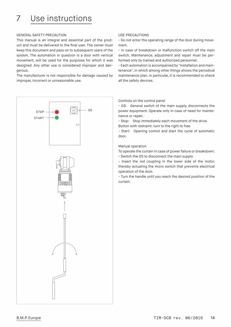
Controlsonthecontrolpanel-GS: Generalswitchofthemainsupply,disconnectsthepowerequipment.Operateonlyincaseofneedformainte-nanceorrepair.-Stop: Stopimmediatelyeachmovementofthedrive.Buttonwithrestraint:turntotherighttofree-Start: Openingcontrol and start thecycleof automaticdoor.
ManualoperationTooperatethecurtainincaseofpowerfailureorbreakdown:-SwitchtheGStodisconnectthemainsupply- Insert the rod coupling in the lower side of the motor,therebyactuatingthemicroswitchthatpreventselectricaloperationofthedoor.-Turnthehandleuntilyoureachthedesiredpositionofthecurtain.
GENERALSAFETYPRECAUTIONThismanual is an integral and essential part of the prod-uctandmustbedeliveredtothefinaluser.Theownermustkeepthisdocumentandpassontosubsequentusersofthesystem.Theautomation inquestion isadoorwithverticalmovement,will beused for thepurposes forwhich itwasdesigned. Any other use is considered improper anddan-gerous.Themanufacturerisnotresponsiblefordamagecausedbyimproper,incorrectorunreasonableuse.
USEPRECAUTIONS-Donotentertheoperatingrangeofthedoorduringmove-ment.- Incaseofbreakdownormalfunctionswitchoff themainswitch.Maintenance, adjustment and repair must be per-formedonlybytrainedandauthorizedpersonnel.-Eachautomationisaccompaniedby"Installationandmain-tenance",inwhichamongotherthingsshowstheperiodicalmaintenanceplan,inparticular,itisrecommendedtocheckallthesafetydevices.
TIM-DCB rev. 06/2016 15B.M.P. Europe
8 Maintenance instructions
Itisnecessarytoperformperiodicinspectionsbyqualifiedtechnicians.Alloperationsmustbecarriedoutinfullcom-pliance with safety regulations, defining and highlightingtheareaofoperations.Beforeanyoperationdisconnecttheelectricalsupplylinebymeansofthemainswitchandpre-ventitcanberestoredbythirdpersons.
Operations to be carried out every six months during themaintenaceinspections:
Safetydevices:–Checktheproper functioningof thesafetyedge(whereprovided)– Check the functioning of the curtain jamming sensor(whereprovided)–Checkthefunctioningofthesafetyphotocell
Automation:–Checkthefunctioningofallthecontroldevicesinstalled(pushbuttons,radar,magneticloopetc.)– Check the electric connections on pugs and terminals,verifiythattherearenowaterleaksordust.-Checkthewearoftheelectricalcomponentsandtheirin-sulation
Sideguides,curtainandframe:-Checkthewearofthesideguides.Donotlubricate:guidesandzippersaremadeofself-lubri-catingmaterials.Theuseofoil,greaseorotherlubricantscreateswithtimethejamofthesliding.-Checkthetensionofthecurtain(seeinstructionsonp23)- Check tightness of the coupling screws of the uprightswithtransom-Checktheanchorofthedoortothebuilding/structure
Motorization:–Checkthetightnessofthemotorfitting– Check the operation of the encoder or limit switches(checkthewearofthecams)–Checkthewearof thebrakediscandverify thebrakingefficiency.
Windingbarrel:–Checkthefixingoftherollingbearings–Checkthebearinglubrication–Checkthealignmentofthewindingbarrel
TIM-DCB rev. 06/2016 16B.M.P. Europe
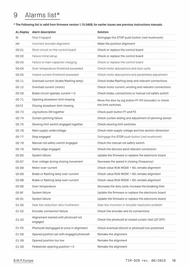
9 Alarms list*
AL display Alarm description Solution
St Stop Engaged DisingagetheSTOPpushbutton(redmushroom)
HH Incorrect encoder alignment Makethepositionalignment
0001 Short circuit on the control board Checkorreplacethecontrolboard
0002 Failure initial setup Checkorreplacethecontrolboard
0003 Failure to main capacitor charging Check or replace the control board
0004 Over-temperature threshold exceeded Check motor absorptions and duty cycle
0005 Instant current threshold exceeded Check motor absorptions and parameters adjustment
0011 Overloadcurrent(brake/flashinglamp) Checkbrake/flashinglampandrelevantconnections
0012 Overloadcurrent(motor) Checkmotorcurrent,windingandrelevantconnections
0050 Brakecircuitopened,current=0 Checkbrake,connectionsormanualrodsafetyswitch
0071 Openingslowdownlimitmissing MovethedoorbyjogbuttonP1-P3(encoder)orcheckthelimitswitches0072 Closingslowdownlimitmissing
0073 JogbuttonsONtogether CheckpushbuttonP1andP3
0074 Curtainjammingfailure Checkcurtainslidingandadjustmentofjammingsensor
0075 Slowinglimitswitchengagedtogether Checkslowinglimitswitches
0076 Mainsupplyundervoltage Checkmainsupplyvoltageandlinesectiondimension
0077 Stopengaged Disingage the STOP push button (red mushroom)
0078 Manualrodsafetyswitchengaged Checkthemanualrodsafetyswitch
0079 Safetyedgeengaged Checkthedevicesaandrelevantconnection
0080 Systemfailure Updatethefirmwareorreplacetheelectronicboard
0087 Overvoltageduringclosingmovement Decreasethespeedinclosing(frequency)
0088 Motorover-current CheckvalueRUNMODE=60,remakealignment
0089 Brakeorflashinglampover-current CheckvalueRUNMODE=60,remakealignment
008B Brakeorflashinglampover-current CheckvalueRUNMODE=60,remakealignment
008D Over-temperature Decreasethedutycycle,increasethebreakingtime
008F Systemfailure Updatethefirmwareorreplacetheelectronicboard
0091 Systemfailure Updatethefirmwareorreplacetheelectronicboard
0100 Gear box reduction ratio incoherent Gear box incorrect or encoder resolution problem
0102 Encoderconnectionfailure Checktheencoderanditsconnections
0103Alignementstartedwithphotocellnotengaged
Checkthephotocellatclosedcurtain(ledLD7OFF)
0105 Photocelldisingagedatonceinalignment Checkeventualdisturborphotocelllowpositoned
0108 Openedpositionsetwithengagedphotocell Remakethealignment
0109 Openedpositiontoolow Remakethealignment
010D Pedestrianopeningposition=0 Remakethealignment
* The Following list is valid from firmware version 1.15.0408, for earlier issues see previous instructions manuals.
TIM-DCB rev. 06/2016 17B.M.P. Europe
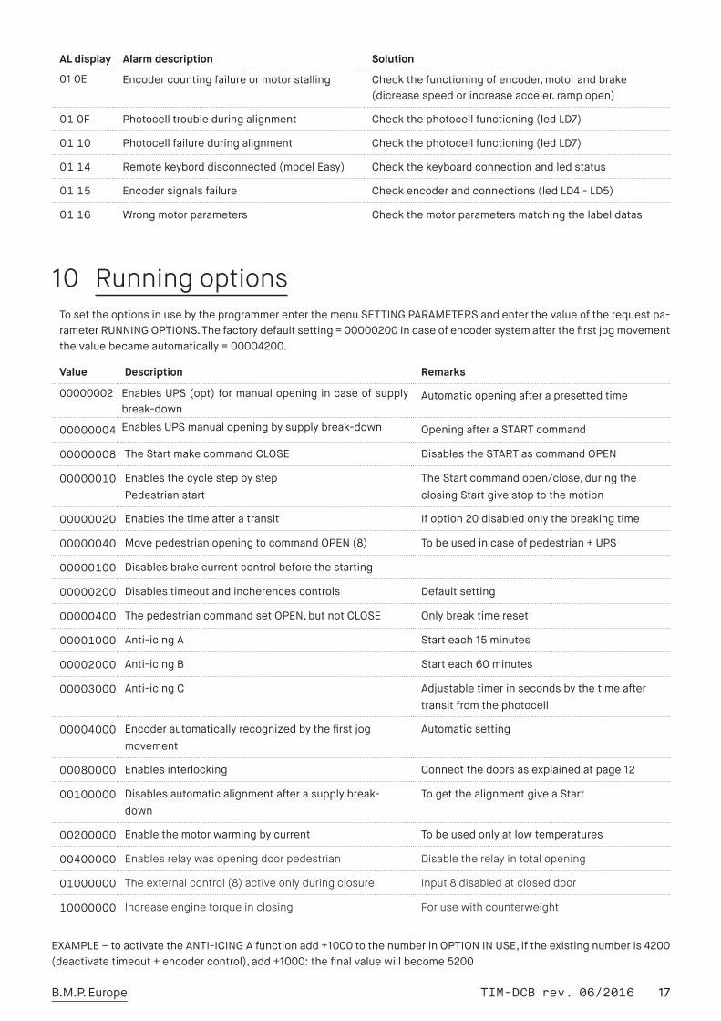
10 Running optionsTosettheoptionsinusebytheprogrammerenterthemenuSETTINGPARAMETERSandenterthevalueoftherequestpa-rameterRUNNINGOPTIONS.Thefactorydefaultsetting=00000200Incaseofencodersystemafterthefirstjogmovementthevaluebecameautomatically=00004200.
EXAMPLE–toactivatetheANTI-ICINGAfunctionadd+1000tothenumberinOPTIONINUSE,iftheexistingnumberis4200(deactivatetimeout+encodercontrol),add+1000:thefinalvaluewillbecome5200
AL display Alarm description Solution
010E Encodercountingfailureormotorstalling Checkthefunctioningofencoder,motorandbrake(dicreasespeedorincreaseacceler.rampopen)
010F Photocelltroubleduringalignment Checkthephotocellfunctioning(ledLD7)
0110 Photocellfailureduringalignment Checkthephotocellfunctioning(ledLD7)
0114 Remotekeyborddisconnected(modelEasy) Checkthekeyboardconnectionandledstatus
0115 Encodersignalsfailure Checkencoderandconnections(ledLD4-LD5)
0116 Wrongmotorparameters Checkthemotorparametersmatchingthelabeldatas
Value Description Remarks
00000002 EnablesUPS(opt)formanualopeningincaseofsupplybreak-down
Automaticopeningafterapresettedtime
00000004 EnablesUPSmanualopeningbysupplybreak-down OpeningafteraSTARTcommand
00000008 TheStartmakecommandCLOSE DisablestheSTARTascommandOPEN
00000010 EnablesthecyclestepbystepPedestrianstart
TheStartcommandopen/close,duringtheclosingStartgivestoptothemotion
00000020 Enablesthetimeafteratransit Ifoption20disabledonlythebreakingtime
00000040 MovepedestrianopeningtocommandOPEN(8) Tobeusedincaseofpedestrian+UPS
00000100 Disablesbrakecurrentcontrolbeforethestarting
00000200 Disablestimeoutandincherencescontrols Defaultsetting
00000400 ThepedestriancommandsetOPEN,butnotCLOSE Onlybreaktimereset
00001000 Anti-icingA Starteach15minutes
00002000 Anti-icingB Starteach60minutes
00003000 Anti-icingC Adjustabletimerinsecondsbythetimeaftertransitfromthephotocell
00004000 Encoderautomaticallyrecognizedbythefirstjogmovement
Automaticsetting
00080000 Enablesinterlocking Connectthedoorsasexplainedatpage12
00100000 Disablesautomaticalignmentafterasupplybreak-down
TogetthealignmentgiveaStart
00200000 Enablethemotorwarmingbycurrent Tobeusedonlyatlowtemperatures
00400000 Enables relay was opening door pedestrian Disable the relay in total opening
01000000 The external control (8) active only during closure Input 8 disabled at closed door
10000000 Increase engine torque in closing For use with counterweight

Related Documents