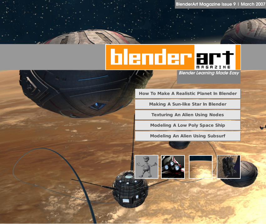
www.blenderart.org 1 Issue 9 March 2007 How To Make A Realistic Planet In Blender Making A Sun-like Star In Blender Texturing An Alien Using Nodes Modeling A Low Poly Space Ship Modeling An Alien Using Subsurf BlenderArt Magazine Issue 9 | March 2007 Blender Learning Made Easy

BlenderArt Magazine Issue 9 Space
Mar 08, 2016
Features Articles/Tutorials on Creating Heatwave Exhaust Effect with the Displace Modifier, How to Make A Realistic Planet In Blender, Making A Sun like Star in Blender, Modeling An Alien Using Subsurf, Texturing An Alien Using Nodes, Modeling a Lowpoly Spaceship, The Making of “Project Utopia” and more…
Welcome message from author
This document is posted to help you gain knowledge. Please leave a comment to let me know what you think about it! Share it to your friends and learn new things together.
Transcript
www.blenderart.org 1 Issue 9 March 2007
How To Make A Realistic Planet In Blender
Making A Sun-like Star In Blender
Texturing An Alien Using Nodes
Modeling A Low Poly Space Ship
Modeling An Alien Using Subsurf
BlenderArt Magazine Issue 9 | March 2007
Blender Learning Made Easy
“Space, the final frontier. These are the voyages ….” Sorry, I just couldn't resist. Star Trek was my first introduction to space as a child. I can still remember watching every week with my father. It had such amazing space scenes and, of course, alien races. It fascinated me then, and continues to fascinate me to this day.
Space is a popular topic among CG artists and 3D modelers. Much of its appeal is due to the fact that there are no hard and fast rules as to how it should look. Anything goes and often does. The fact that telescopes have now charted and photographed sections of space only fuels the imagination.
Actual star fields and nebulae become the backgrounds to frame our fantastical space ships and aliens. Meteor showers rain past alien planets as ships battle nearby. From highly detailed space ships to often bizarre looking aliens, CG art is filled with space scenes taken directly from our deepest imaginations.
In this issue, we have a wide array of tutorials covering a variety of space topics. We discuss some of the best ways to set up star fields as well as discuss some of the pitfalls of lighting in space. We have in-depth tutorials on creating Sun-like stars and a realistic planet. And of course, no issue on
Space would be complete without spaceships and aliens.
Whatever your interest in Space, we have you covered. Also, this issue brings back the popular “Meet the Blenderhead” series of articles by Derek Marsh, (BgDM), as he interviews Ecks, (Jean-Sébastien Guillemette).
So get ready for your own grand space adventure that is waiting for you.
Happy Blending!
www.blenderart.org 2 Issue 9 March 2007
Sandra GilbertManaging Editor
EDITORIAL
www.blenderart.org 3 Issue 9 March 2007
CONTENTS
EDITOR/DESIGNERGaurav Nawani [email protected]
MANAGING EDITORSandra Gilbert [email protected]
WEBSITENam Pham [email protected]
PROOFERKernon DillonPhillip A.RyalsKevin C. BraunDerek MarshBruce Westfall
WRITERSKostis KarvouniariEnrico ValenzaLuís BeleriqueTim KennedyRobbert Fos terDerek Marsh
COPYRIGHT© 2006‘BlenderArt Magazine’,‘blenderart’ and BlenderArt logo are copyright of Gaurav Nawani. ‘Izzy’ and ‘Izzy logo’ are copyright Sandra Gilbert. All products and company names featured in the publication are trademark or regis tered trade marks of their respective owners .
COVER ARTEnrico Valenza - ' Golden Ships '
7
11
16
22
37
42
46
Creating A Heatwave Exhaust Effect With The Displace Modifier
How To Make A Realistic Planet In Blender
Making A Sun-like Star In Blender
Modeling An Alien Using Subsurf
Texturing An Alien Using Nodes
Modeling A Low Poly Space Ship
The Making Of 'Project Utopia'
February was a great month for Blender fans.
Blender 2.43 released with an amazing set of new features and improvements. It can be downloaded at http://www.blender.org/download/get-blender/. In addition to the Release Notes, this version also has some very nice demo videos showcasing the new features.
The same day Blender 2.43 was released, www.blender.org unveiled its new website design. Sporting an edgy new look; the website has completed its first target in the website migration project by migrating the core blender.org site to a new server and redesigning the content and templates. Since not all content pages fit nicely into the new design, look for further changes as everything is redone and placed into the new design.
The long awaited book, Introducing Character Animation with Blender by Tony Mullen (bugman_2000), is on sale at Amazon(http://www.amazon.com/Introducing-Character-Animation-Blender-DVD/pd/0470102608).
At the time of writing this article, the price was still at the pre-sale amount of $26.39 USD.
There are Look Inside!(tm) pages available to give you a sneak peek at what to expect. Everyone that has already received their copy, is very impressed with the quality of the book. Well done Tony! BlenderArt wishes you and your book all the best!
March GoodnessPlumiferos is presenting a fresh new trailer with real sequences from the film at the 22nd Mar del Plata Film Festival on March 10th. Additionally, they will be presenting several completed sequences in a special session that day.
'Essential Blender', is now available for pre-sale orders. (EUR 29/34.52 USD)'Essential Blender' the next book from the Blender Foundation, is your official guide to learning the fundamentals of this open and free 3D software suite. The book can be used as a step-by-step guide for people new to Blender or new to the latest changes in Blender.This book is the ideal companion for the previous 2.3 Blender guide.
'Essential Blender' will get you working with modeling, materials and texturing, lighting, particle systems, several kinds of animation, and rendering. In addition, there are chapters on the new mesh sculpting tools and the brilliant compositor. For users familiar with other 3D packages, there are separate indices that reference topics using your application's terminology.
If you've been looking for a way to give yourself a solid foundation in the basic tools and techniques of Blender, 'Essential Blender' is there for you!
The book editor, Roland Hess, is a professional writer and Blender user for almost a decade. He has brought together a team of the best writers and artists in the Blender community to help on creating this new standard Blender guide.
* Up to date with (upcoming) 2.44 Blender* About 350 pages B&W* Stitched binding, quality paper, full color cover* DVD Rom with all necessary files and demos* Shipping expected to start 2nd week May.
www.blenderart.org 4 Issue 9 March 2007
Blender News
Lighting in Space
Outer space scenes can be one of the most challenging areas to light properly. Let’s face it, space is filled with random areas of faint to intense light from stars and reflected light from planets and moons. But in between those areas of over-abundant light, there is a whole lot of darkness; serious, inky, black darkness where you can’t even see your hand in front of your face.
If you are going for a realistic render, chances are your scene would look rather poorly lit or blown out, depending on where you choose to stage your scene. Fortunately, or unfortunately (depending on how you look at it), Hollywood has set the
standard for space scenes to appear well lit no matter where the scene is staged.
That being the case, let’s discuss how to light Hollywood’s idea of a realistic space scene. Now as a normal rule when deciding on lighting, you would go visit/investigate or do some research on the type of scene you were creating. But since my spaceship and spacesuit are on back order, we will have to take an imaginary trip to check out our lighting options.
So here we are, in outer space. I parked my spaceship in the first empty sector of space I came to (wouldn’t want to interfere with anyone else’s lighting research), climbed into my spacesuit and went outside for a look. Hmmm, it’s awfully dark out here. In fact, I can’t see anything. Whoops, forgot to turn my helmet light on. Hehe, well now I can see my hands, but I still can’t see my spaceship. I know it’s over there somewhere. Maybe if I turn on my ship’s running lights. Now where did I put that remote, ah there it is. Beep, beep; there it is. Now my ship is visible, sort of.
Just my luck, I didn’t purchase the “light it up perfectly” add-on package for my ship. Well this obviously isn’t going to work. Not only can I barely see my spaceship, but I can tell right away that the rendered image is going to be very boring. Who wants to
look at a barely lit spaceship sitting in a sea of total black; time to change locations.
Okay, now I have moved my spaceship into a nice galaxy that has a rather beautiful blue nebula. In fact, this is going to make a nice background for my image; back into the spacesuit. Once I have gone back outside, I notice that not only is my spaceship lit nicely, but that there are some lovely blue reflections from the nebula that will add a nice effect to my image. Also, my running lights now appear to actually be helping the scene by lighting up areas that aren’t receiving any reflected light from the nebula or nearby stars.
Back on Earth at our computer, let’s discuss what we learned from our research.
• Space is very dark.
• Turning on the running lights on your spaceship can be an effective way to light up areas that aren’t receiving any direct or reflected light, allowing the spaceship to stand out better from the space background.
• Location is very important when staging a space scene; make sure there are logical reasons for the lights you are going to add.
www.blenderart.org 5 Issue 9 March 2007
Izzy Speaks – Space Scenes
• Use stars/suns to create direct light; nebulae, moons and planets to mimic reflected light.
• Don’t forget, when adding your light-source space elements, to set your lamps to match the color of the space element. A blue nebula isn't going to cast white studio light. Matching the color of the space element will tie your ship more firmly into the scene.
• While it wasn’t overly obvious from our research, keep in mind that shadows still play an important part in your scene. Use just enough light to illuminate your model, but don’t light it so much that you lose all shadows. Remember, space is dark.
• Also remember that some of your space elements should cast shadows, like planets, moons asteroids, and space debris. Try not to park your space ship fully in the shadow of large shadow casting elements. It will end up being harder to convincingly light your spaceship.
Well with our research completed, we
can add our lights and space elements to our scene and render out our beautiful Hollywood space scene ■
www.blenderart.org 6 Issue 9 March 2007
Izzy Speaks – Space Scenes
By Kostis Karvouniaris
Level: Beginner to Intermediate
IntroductionFor quite some time, a question has been circulating through forums and mail columns about an uncommon effect in 3d applications: How do I simulate the distortion caused by hot air masses? We've all seen this in real life - the waviness in the air during Formula 1 races, in jet engine exhaust, and above camp fires. However, in keeping with this issue's theme, we're going to use the effect in a space scene.
Rendering the background
The inputs for the displace node are relatively simple: It needs an image to be distorted, and a displacement factor in the form of a vector. In this example I've used a particle generator for each engine, which will generate a series of black and white images for use as the displacement factor for the node. Confused? Just follow the steps and it will become clear. For reasons
of simplicity and speed, this is a static scene. The spacecraft is warming up it's engines in preparation for launch, which means I only had to render the background image once. I then used that image in all of the sequence frames. The particles are the only moving element.
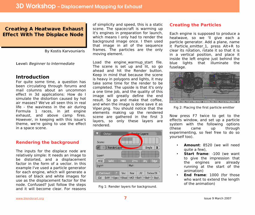
Load the engine_warmup_start file. The scene is set up and lit, so go ahead and hit the Render button. Keep in mind that because the scene is heavy in polygons and lights, it may take some time for the render to be completed. The upside is that it's only a one time job, and the quality of this image will greatly define the end result. So go and make that coffee, and when the image is done save it as Viper.png. You should notice that the elements making up the rendered scene are gathered in the first 3 layers, so only these layers are rendered.
Fig 1: Render layers for background.
Creating the Particles
Each engine is supposed to produce a heatwave, so we 'll give each a particle generator. Add a plane, name it Particle_emitter_1, press Alt+R to clear its rotation, rotate it so that it is in a vertical position, and place it inside the left engine just behind the blue lights that illuminate the fuselage.
Fig 2: Placing the first particle emitter
Now press F7 twice to get to the effects window, and set up a particle system with the following options (these came up through experimenting, so feel free to do so yourself too).
• Amount: 8520 (we will need quite a few),
• Start frame: -100 (we want to give the impression that the engines are already running at the start of the animation)
• End frame: 1000 (for those who want to extend the length of the animation)
www.blenderart.org 7 Issue 9 March 2007
3D Workshop – Displacement Mapping for Exhaust
Creating A Heatwave Exhaust Effect With The Displace Node
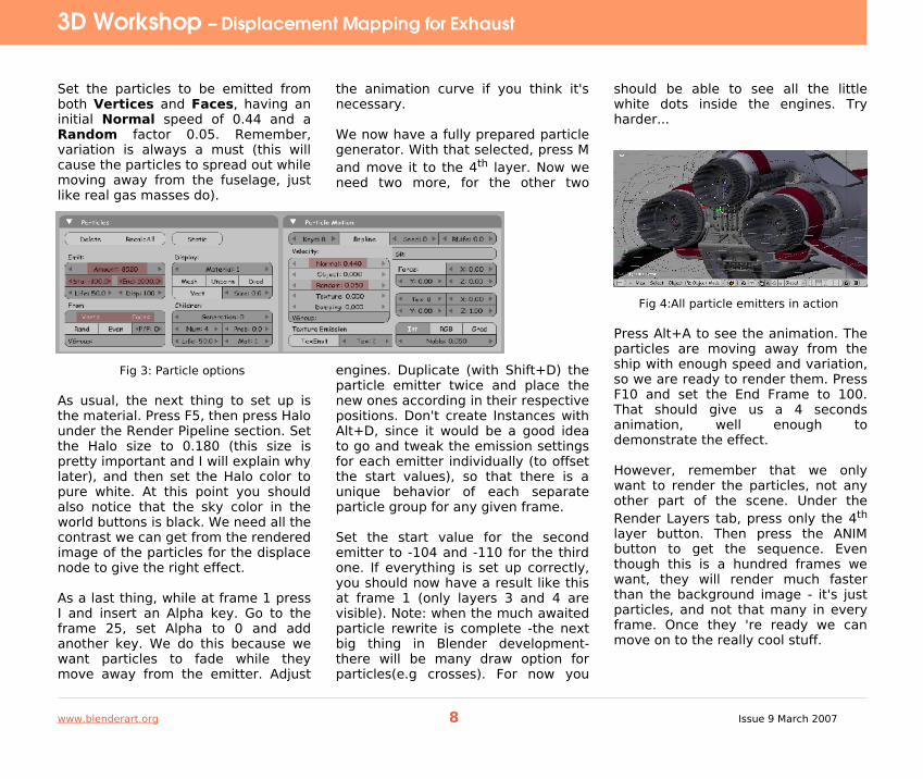
Set the particles to be emitted from both Vertices and Faces, having an initial Normal speed of 0.44 and a Random factor 0.05. Remember, variation is always a must (this will cause the particles to spread out while moving away from the fuselage, just like real gas masses do).
Fig 3: Particle options
As usual, the next thing to set up is the material. Press F5, then press Halo under the Render Pipeline section. Set the Halo size to 0.180 (this size is pretty important and I will explain why later), and then set the Halo color to pure white. At this point you should also notice that the sky color in the world buttons is black. We need all the contrast we can get from the rendered image of the particles for the displace node to give the right effect.
As a last thing, while at frame 1 press I and insert an Alpha key. Go to the frame 25, set Alpha to 0 and add another key. We do this because we want particles to fade while they move away from the emitter. Adjust
the animation curve if you think it's necessary.
We now have a fully prepared particle generator. With that selected, press M and move it to the 4th layer. Now we need two more, for the other two
engines. Duplicate (with Shift+D) the particle emitter twice and place the new ones according in their respective positions. Don't create Instances with Alt+D, since it would be a good idea to go and tweak the emission settings for each emitter individually (to offset the start values), so that there is a unique behavior of each separate particle group for any given frame.
Set the start value for the second emitter to -104 and -110 for the third one. If everything is set up correctly, you should now have a result like this at frame 1 (only layers 3 and 4 are visible). Note: when the much awaited particle rewrite is complete -the next big thing in Blender development- there will be many draw option for particles(e.g crosses). For now you
should be able to see all the little white dots inside the engines. Try harder...
Fig 4:All particle emitters in action
Press Alt+A to see the animation. The particles are moving away from the ship with enough speed and variation, so we are ready to render them. Press F10 and set the End Frame to 100. That should give us a 4 seconds animation, well enough to demonstrate the effect.
However, remember that we only want to render the particles, not any other part of the scene. Under the Render Layers tab, press only the 4th
layer button. Then press the ANIM button to get the sequence. Even though this is a hundred frames we want, they will render much faster than the background image - it's just particles, and not that many in every frame. Once they 're ready we can move on to the really cool stuff.
www.blenderart.org 8 Issue 9 March 2007
3D Workshop – Displacement Mapping for Exhaust
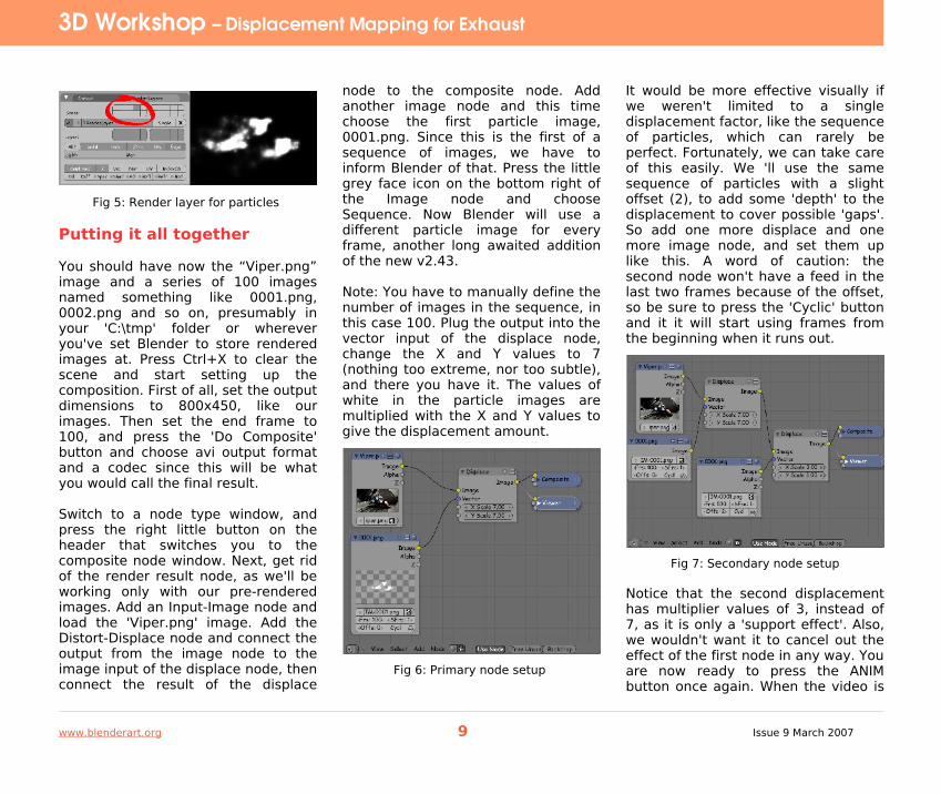
Fig 5: Render layer for particles
Putting it all together
You should have now the “Viper.png” image and a series of 100 images named something like 0001.png, 0002.png and so on, presumably in your 'C:\tmp' folder or wherever you've set Blender to store rendered images at. Press Ctrl+X to clear the scene and start setting up the composition. First of all, set the output dimensions to 800x450, like our images. Then set the end frame to 100, and press the 'Do Composite' button and choose avi output format and a codec since this will be what you would call the final result.
Switch to a node type window, and press the right little button on the header that switches you to the composite node window. Next, get rid of the render result node, as we'll be working only with our pre-rendered images. Add an Input-Image node and load the 'Viper.png' image. Add the Distort-Displace node and connect the output from the image node to the image input of the displace node, then connect the result of the displace
node to the composite node. Add another image node and this time choose the first particle image, 0001.png. Since this is the first of a sequence of images, we have to inform Blender of that. Press the little grey face icon on the bottom right of the Image node and choose Sequence. Now Blender will use a different particle image for every frame, another long awaited addition of the new v2.43.
Note: You have to manually define the number of images in the sequence, in this case 100. Plug the output into the vector input of the displace node, change the X and Y values to 7 (nothing too extreme, nor too subtle), and there you have it. The values of white in the particle images are multiplied with the X and Y values to give the displacement amount.
Fig 6: Primary node setup
It would be more effective visually if we weren't limited to a single displacement factor, like the sequence of particles, which can rarely be perfect. Fortunately, we can take care of this easily. We 'll use the same sequence of particles with a slight offset (2), to add some 'depth' to the displacement to cover possible 'gaps'. So add one more displace and one more image node, and set them up like this. A word of caution: the second node won't have a feed in the last two frames because of the offset, so be sure to press the 'Cyclic' button and it it will start using frames from the beginning when it runs out.
Fig 7: Secondary node setup
Notice that the second displacement has multiplier values of 3, instead of 7, as it is only a 'support effect'. Also, we wouldn't want it to cancel out the effect of the first node in any way. You are now ready to press the ANIM button once again. When the video is
www.blenderart.org 9 Issue 9 March 2007
3D Workshop – Displacement Mapping for Exhaust
ready you can set your media player to loop playback and play the file. The particle movement is random anyway, so you won't be able to tell where the video starts or ends.
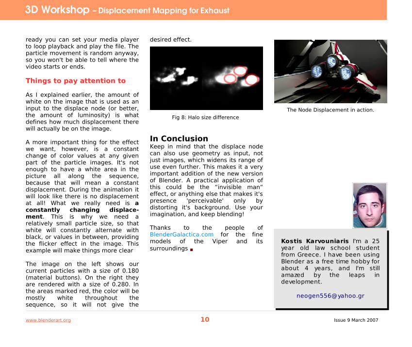
Things to pay attention to
As I explained earlier, the amount of white on the image that is used as an input to the displace node (or better, the amount of luminosity) is what defines how much displacement there will actually be on the image.
A more important thing for the effect we want, however, is a constant change of color values at any given part of the particle images. It's not enough to have a white area in the picture all along the sequence, because that will mean a constant displacement. During the animation it will look like there is no displacement at all! What we really need is a constantly changing displace-ment. This is why we need a relatively small particle size, so that white will constantly alternate with black, or values in between, providing the flicker effect in the image. This example will make things more clear
The image on the left shows our current particles with a size of 0.180 (material buttons). On the right they are rendered with a size of 0.280. In the areas marked red, the color will be mostly white throughout the sequence, so it will not give the
desired effect.
Fig 8: Halo size difference
In Conclusion Keep in mind that the displace node can also use geometry as input, not just images, which widens its range of use even further. This makes it a very important addition of the new version of Blender. A practical application of this could be the “invisible man“ effect, or anything else that makes it's presence 'perceivable' only by distorting it's background. Use your imagination, and keep blending!
Thanks to the people of BlenderGalactica.com for the fine models of the Viper and its surroundings ■
The Node Displacement in action.
www.blenderart.org 10 Issue 9 March 2007
Kostis Karvouniaris I'm a 25 year old law school student from Greece. I have been using Blender as a free time hobby for about 4 years, and I'm still amazed by the leaps in development.
3D Workshop – Displacement Mapping for Exhaust
by Enrico Valenza
Introduction
This tutorial works also with versions of Blender earlier than 2.30, other than that I had to fake the fresnel effect in 2.23. To fake the fresnel effect, I used two methods: the first, the faster for rendering used a "blend" procedural texture; the second, slower
for rendering but more effective method used a circular set of dupliverted lamps to light up the "borders" of the planet.
Above you can see the effects of the both the techniques. Blender 2.4x has a true fresnel effect so we don't need to fake it anymore.
Following are the techniques I used for rendering the planet scene as in image "Golden Planet", using Blender ver. 2.31a.
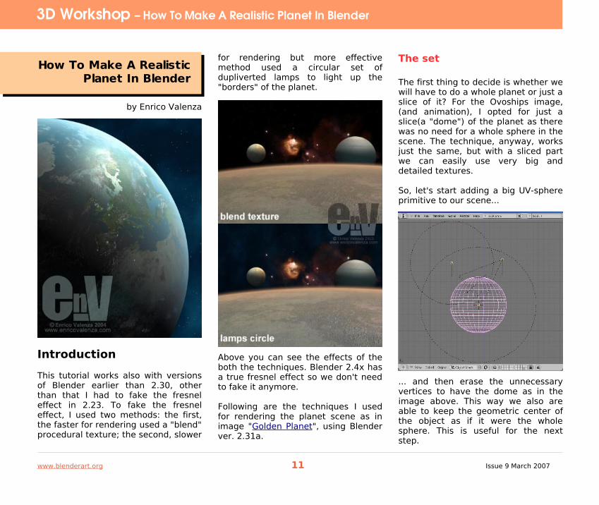
The set
The first thing to decide is whether we will have to do a whole planet or just a slice of it? For the Ovoships image, (and animation), I opted for just a slice(a "dome") of the planet as there was no need for a whole sphere in the scene. The technique, anyway, works just the same, but with a sliced part we can easily use very big and detailed textures.
So, let's start adding a big UV-sphere primitive to our scene...
... and then erase the unnecessary vertices to have the dome as in the image above. This way we also are able to keep the geometric center of the object as if it were the whole sphere. This is useful for the next step.
www.blenderart.org 11 Issue 9 March 2007
How To Make A Realistic Planet In Blender
3D Workshop – How To Make A Realistic Planet In Blender
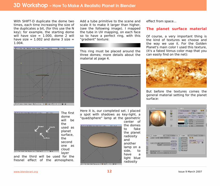
With SHIFT-D duplicate the dome two times, each time increasing the size of the duplicates a bit, (for this use the N key); for example, the starting dome will have size = 1.000, dome 2 will have size = 1.002 and dome 3 size = 1.004.
The first dome will be the used as planet surface, the second one as cloud layer
and the third will be used for the fresnel effect of the atmosphere.
Add a tube primitive to the scene and scale it to make it larger than higher, (see the following image). I mapped the tube in UV mapping, on each face so to have a perfect ring, with this "gradient" texture:
This ring must be placed around the three domes; more details about the material at page 4.
Here it is, our completed set. I placed a spot with shadows as key-light, a "quad/sphere" lamp at the geometric
center of the domes to fake the planet radiosity and another lamp on a side, to have a light blue radiosity
effect from space...
The planet surface material
Of course, a very important thing is the kind of textures we choose and the way we use it. For the Golden Planet's main color I used this texture, (it's a faked Venus color map that you can easily find on the net):
But before the textures comes the general material setting for the planet surface:
www.blenderart.org 12 Issue 9 March 2007
3D Workshop – How To Make A Realistic Planet In Blender
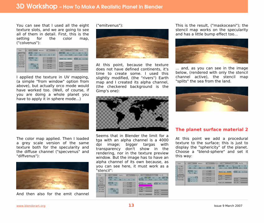
You can see that I used all the eight texture slots, and we are going to see all of them in detail. First, this is the setting for the color map, ("colvenus"):
I applied the texture in UV mapping, (a simple "from window" option from above), but actually orco mode would have worked too. (Well, of course, if you are doing a whole planet you have to apply it in sphere mode...)
The color map applied. Then I loaded a grey scale version of the same texture both for the specularity and the diffuse channel ("specvenus" and "diffvenus"):
And then also for the emit channel
("emitvenus"):
At this point, because the texture does not have defined continents, it's time to create some. I used this slightly modified, (the "rivers") Earth map and I created its alpha channel, (the checkered background is the Gimp's one):
Seems that in Blender the limit for a tga with an alpha channel is a 4000 dpi image; bigger targas with transparency don't show in the rendering, nor in the texture preview window. But the image has to have an alpha channel of its own because, as you can see here, it must work as a "stencil":
This is the result, ("maskoceani"); the stencil map works on the specularity and has a little bump effect too...
... and, as you can see in the image below, (rendered with only the stencil channel active), the stencil map "splits" the sea from the land.
The planet surface material 2
At this point we add a procedural texture to the surface; this is just to display the "sphericity" of the planet. Choose a "blend-sphere" and set it this way:
www.blenderart.org 13 Issue 9 March 2007
3D Workshop – How To Make A Realistic Planet In Blender
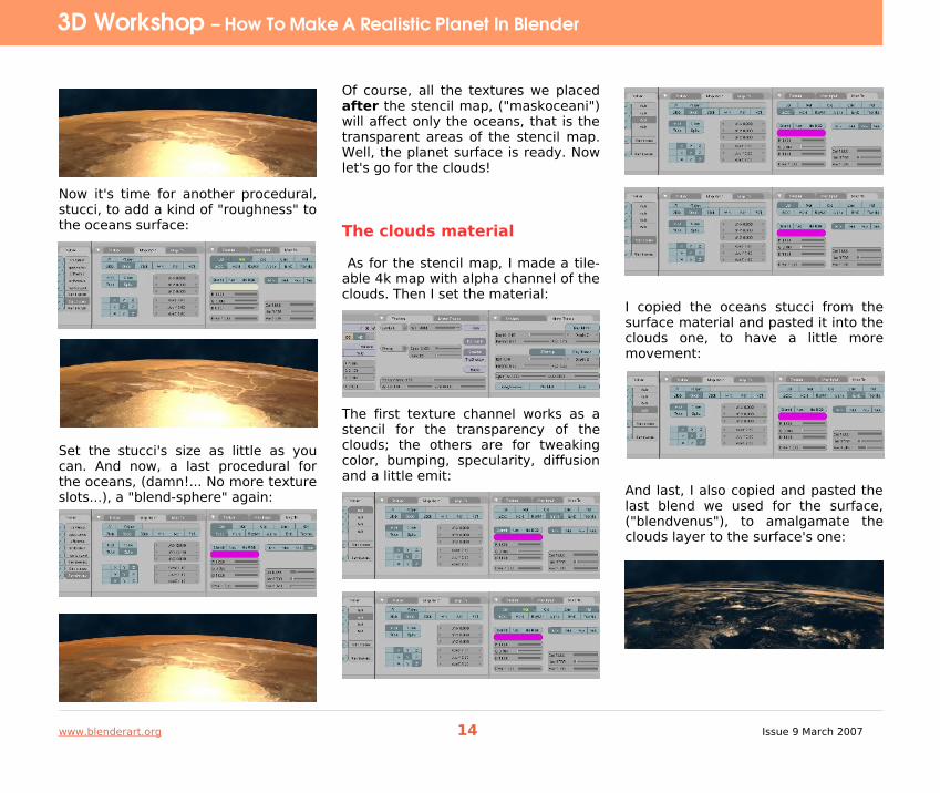
Now it's time for another procedural, stucci, to add a kind of "roughness" to the oceans surface:
Set the stucci's size as little as you can. And now, a last procedural for the oceans, (damn!... No more texture slots...), a "blend-sphere" again:
Of course, all the textures we placed after the stencil map, ("maskoceani") will affect only the oceans, that is the transparent areas of the stencil map.Well, the planet surface is ready. Now let's go for the clouds!
The clouds material
As for the stencil map, I made a tile-able 4k map with alpha channel of the clouds. Then I set the material:
The first texture channel works as a stencil for the transparency of the clouds; the others are for tweaking color, bumping, specularity, diffusion and a little emit:
I copied the oceans stucci from the surface material and pasted it into the clouds one, to have a little more movement:
And last, I also copied and pasted the last blend we used for the surface, ("blendvenus"), to amalgamate the clouds layer to the surface's one:
www.blenderart.org 14 Issue 9 March 2007
3D Workshop – How To Make A Realistic Planet In Blender
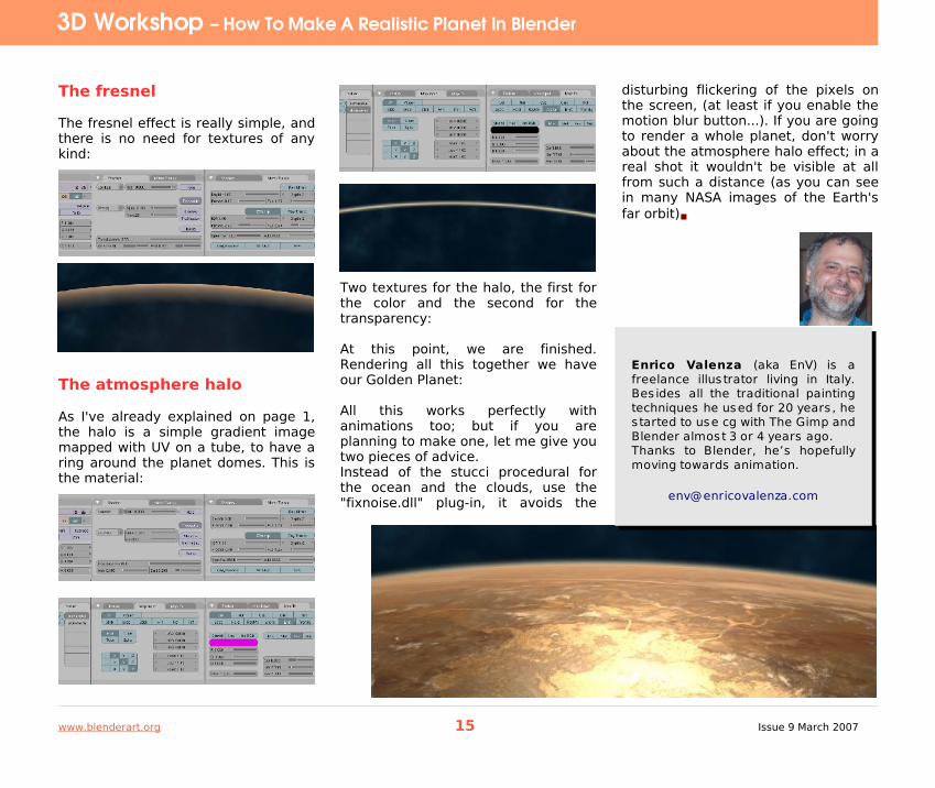
The fresnel
The fresnel effect is really simple, and there is no need for textures of any kind:
The atmosphere halo
As I've already explained on page 1, the halo is a simple gradient image mapped with UV on a tube, to have a ring around the planet domes. This is the material:
Two textures for the halo, the first for the color and the second for the transparency:
At this point, we are finished. Rendering all this together we have our Golden Planet:
All this works perfectly with animations too; but if you are planning to make one, let me give you two pieces of advice.Instead of the stucci procedural for the ocean and the clouds, use the "fixnoise.dll" plug-in, it avoids the
disturbing flickering of the pixels on the screen, (at least if you enable the motion blur button...). If you are going to render a whole planet, don't worry about the atmosphere halo effect; in a real shot it wouldn't be visible at all from such a distance (as you can see in many NASA images of the Earth's far orbit)■
www.blenderart.org 15 Issue 9 March 2007
3D Workshop – How To Make A Realistic Planet In Blender
Enrico Valenza (aka EnV) is a freelance illus trator living in Italy. Bes ides all the traditional painting techniques he used for 20 years , he started to use cg with The Gimp and Blender almost 3 or 4 years ago.Thanks to Blender, he’s hopefully moving towards animation.
by Luís Belerique
Level: Intermediate
IntroductionStars are the most famous astronomical objects, besides planets and dangerous comets and asteroids. When making a movie in space, most of the time they're just specks of light against the blackness of space. But sometimes it is needed to see a star very close to the camera. The objective of this tutorial is to do a Sun-like star that can be seen up close, that will be animated and using only procedural textures.
In this tutorial I will be using Blender 2.43, but it can also be made in 2.42a. Before starting this tutorial, you should get some reference images for studying and inspirational purposes. Just a small note, this tutorial is a result of experiments I made when trying to create a Sun, so some settings are the best that I found for my project, as a result of trial and error. So you are invited to use them only as guidelines, not absolute truths.
Making the Sun
Step 1: Photosphere
First of all, you must know the very basics of Blender's interface. If that is not the case, go here (http://wiki.blender.org/index.php/Manual/The_Interface).
Open up Blender, and if you have the default scene, erase the cube with [x] or [Del]. Now add a sphere; Add>>Mesh>>UVsphere and use the default values of 32 for Rings and Segments. Now change from Edit Mode to Object Mode [Tab]. In the Buttons Window, in Editing context [F9], click on the "Set Smooth" button in the "Links and Materials" panel to get rid of the faceted look.
From now on, most of the work will be done in the material of the sphere, so let's add a new material to the sphere. Change context of the buttons Window to "Shading" by pressing [F5] in the panel "Links and Pipeline", press the "Add New" button. Now our Sun has a material but it's grey and dull, nothing like a star.
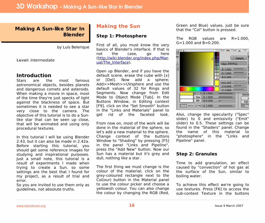
The first thing we must change is the colour of the material; click on the grey-coloured rectangle next to the Col(our) button in the Material panel to use the colour picker and choose a yellowish colour. You can also change the colour by changing the RGB (Red,
Green and Blue) values, just be sure that the "Col" button is pressed.
The RGB values are R=1.000, G=1.000 and B=0.200.
Also, change the specularity ("Spec" slider) to 0 and emissivity ("Emit" slider) to 0.5. These settings can be found in the "Shaders" panel. Change the name of this material to "photosphere" in the "Links and Pipeline" panel.
Step 2: Granules
Time to add granulation, an effect caused by "convection" of hot gas at the surface of the Sun, similar to boiling water.
To achieve this effect we're going to use textures. Press [F6] to access the sub-context Texture in the buttons
www.blenderart.org 16 Issue 9 March 2007
Making A Sun-like Star In Blender
3D Workshop – Making A Sun-like Star In Blender
window. Now we're going to create a new texture by clicking on the "Add New" button and then in the texture Type menu choose "Voronoi". This kind of texture is very good to simulate veins, scales and also the granulation at the Sun's surface. Change the name of the texture to "convection" by clicking on the name and editing it. It's a good idea to keep "logical" names in textures, materials and so on. To the right appears a new panel, called "Voronoi".
Here you can change some parameters of this texture, like the size of the "cells". Change the "Size" parameter to 0.050, like the image below.
Going back to the "Material" sub-context [F5] we see in the preview
that our Sun yellow has now pink "granules". A texture can alter several aspects of a material, like colour or transparency. By default, every new texture affects the colour of the material and this colour is pink.
To change the colour of our texture, go to the "Map To" panel (usually it's the rightmost panel). In this panel we see the different kind of effects that a
texture can do to a material, and notice that the "Col" button is pressed. Below you can see a pink rectangle. Click on it and use the colour picker to choose a more orange colour (R=1.000, G=0.465, B=0.000).
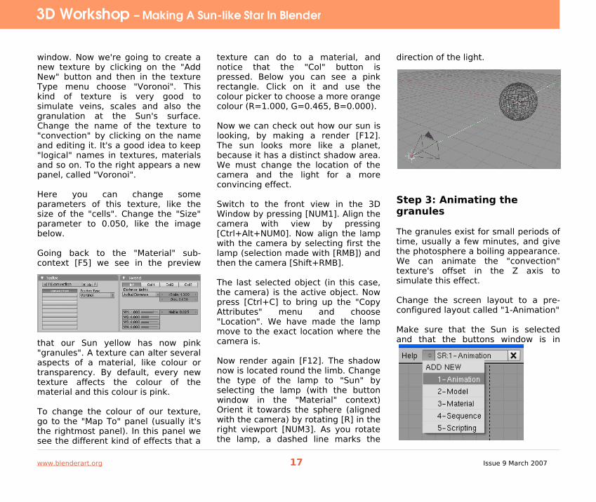
Now we can check out how our sun is looking, by making a render [F12]. The sun looks more like a planet, because it has a distinct shadow area. We must change the location of the camera and the light for a more convincing effect.
Switch to the front view in the 3D Window by pressing [NUM1]. Align the camera with view by pressing [Ctrl+Alt+NUM0]. Now align the lamp with the camera by selecting first the lamp (selection made with [RMB]) and then the camera [Shift+RMB].
The last selected object (in this case, the camera) is the active object. Now press [Ctrl+C] to bring up the "Copy Attributes" menu and choose "Location". We have made the lamp move to the exact location where the camera is.
Now render again [F12]. The shadow now is located round the limb. Change the type of the lamp to "Sun" by selecting the lamp (with the button window in the "Material" context) Orient it towards the sphere (aligned with the camera) by rotating [R] in the right viewport [NUM3]. As you rotate the lamp, a dashed line marks the
direction of the light.
Step 3: Animating the granules
The granules exist for small periods of time, usually a few minutes, and give the photosphere a boiling appearance. We can animate the "convection" texture's offset in the Z axis to simulate this effect.
Change the screen layout to a pre-configured layout called "1-Animation"
Make sure that the Sun is selected and that the buttons window is in
www.blenderart.org 17 Issue 9 March 2007
3D Workshop – Making A Sun-like Star In Blender
"Shading" context and "Material" sub-context. To the right you can see the "IPO Curve Editor". Normally, the IPO window shows parameters related to an object, like location or rotation. But we're more interested in parameters related to the material of the object, so change to "Material" in the menu located in the header of the IPO window.
To the right of the IPO window we can see the list of parameters, known as "channels". We can scroll up and down this list by pressing [MMB] and moving the mouse up or down. Scroll down for the channel "OfsZ", then select it with [LMB]. The lettering will become white and a grey rectangle will appear to the left of the name, indicating that this channel is selected.
Now click with [CTRL+LMB] once in the main area of the IPO window. A white dot and a purple line will appear. Now click again with [Ctrl+LMB], on a different place. A second white dot appears where you clicked and the IPO curve now draws a curve between the two keyframes (the white dots). Now, extend the IPO curve infinitely by choosing Curve>>Extend Mode>>Extrapolation.
The steepness of this line affects the rate at which changes the Z offset; the steeper the line the faster it changes the Z offset. You can change
the steepness by entering in edit mode [TAB], selecting one of the control vertices with [RMB] and moving it with [G] and finally exiting edit mode [TAB].
A final step must be made, we must change how the texture is mapped to the sphere. In the "Material" sub-context [F5], go to the "Map Input" panel and modify the settings of the matrix on the bottom according to the image below.
If you wish, you can go back to the "2-Model" screen layout.
Step 4: Limb Darkening
Now we're going to recreate the effect of "limb darkening" visible on the Sun, with the help of Ramp Shaders (For more info on the Ramp Shaders, visit http://wiki.blender.org/index.php/Manual/PartIII/Ramp_Shaders).
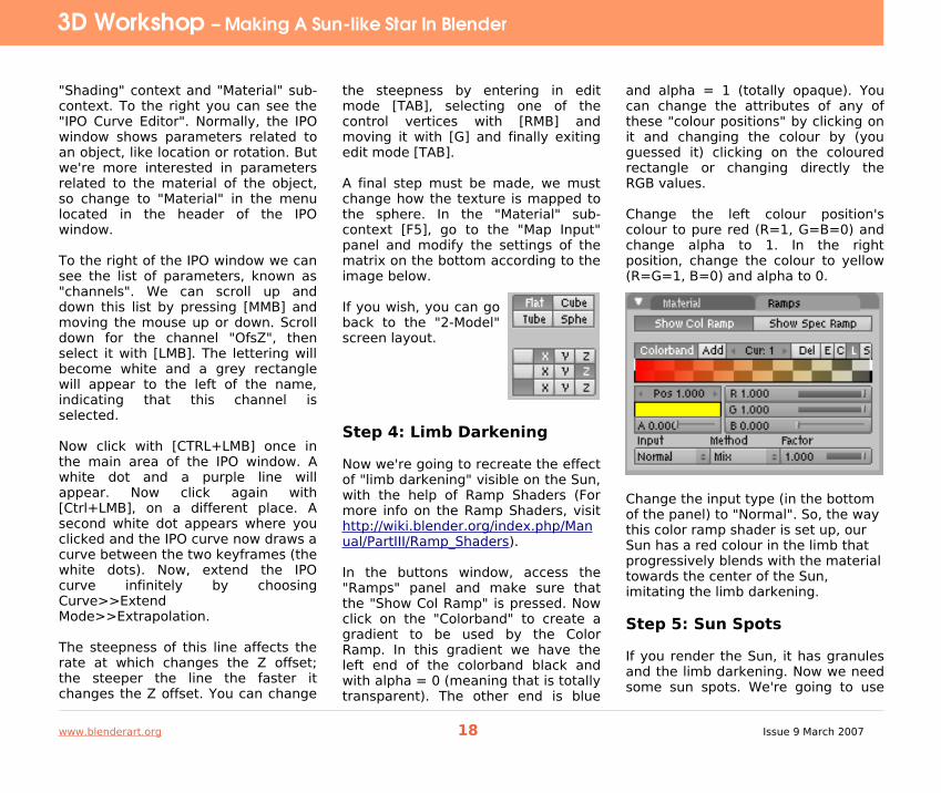
In the buttons window, access the "Ramps" panel and make sure that the "Show Col Ramp" is pressed. Now click on the "Colorband" to create a gradient to be used by the Color Ramp. In this gradient we have the left end of the colorband black and with alpha = 0 (meaning that is totally transparent). The other end is blue
and alpha = 1 (totally opaque). You can change the attributes of any of these "colour positions" by clicking on it and changing the colour by (you guessed it) clicking on the coloured rectangle or changing directly the RGB values.
Change the left colour position's colour to pure red (R=1, G=B=0) and change alpha to 1. In the right position, change the colour to yellow (R=G=1, B=0) and alpha to 0.
Change the input type (in the bottom of the panel) to "Normal". So, the way this color ramp shader is set up, our Sun has a red colour in the limb that progressively blends with the material towards the center of the Sun, imitating the limb darkening.
Step 5: Sun Spots
If you render the Sun, it has granules and the limb darkening. Now we need some sun spots. We're going to use
www.blenderart.org 18 Issue 9 March 2007
3D Workshop – Making A Sun-like Star In Blender
another procedural texture for this. This will be a similar procedure to the one used in making the granules.
Activate the "Textures" sub-context [F6] and click on the free texture slot just below the "convection" slot. Add a new texture and name it "sun spots". Choose for texture type "Musgrave". A new panel, called "Musgrave" appears where you can change the settings related to this texture. Change the Musgrave type (the menu at the top of the panel) to "Hybrid Multifractal" and change the remaining settings as described in the screenshot below.Once again we can render [F12] an
image to see the result, but you will see the Sun bathed in pink, with only some yellow patches. The pink colour should be expected by now (see the explanation in the Granules section). But the effect should be reversed...we only want small black patches on the Sun.
How to solve this problem? Simple, use a colorband. Go to the "Color" panel. Here we're going to use a colorband to "invert" the effect. Use the image below as guide. Notice that the position of the right
end is at 0.600, you can change it in the "Pos" slider, making the colorband become transparent "earlier". This will allow for smaller and fewer patches, looking more similar to sun spots. Render another image to see the effect.
If you move the left end of the colorband closer to the right end, the contrast of the spots will increase, making them more visible.
Finally, we are done making the photosphere of our star. Now we move on making other elements present in the atmosphere of a Sun-like star, starting by the solar corona.
Step 6: Solar Corona - Particle System
The Solar Corona surrounds the photosphere, and is composed of very hot gases but it has a very low density, only visible to us during a total solar eclipse. But here we're going to depart from the scientifically correct. Change to a different layer, for example if you have been working in layer 1, change to layer 2 by pressing [2]. Here we add another
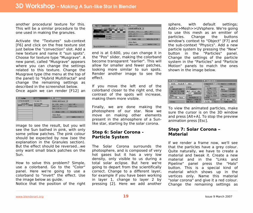
sphere, with default settings; Add>>Mesh>>UVsphere. We're going to use this mesh as an emitter of particles. Change the buttons window's context to "Object" [F7] and the sub-context "Physics". Add a new particle system by pressing the "New" button in the "Particles" panel. Change the settings of the particle system in the "Particles" and "Particle Motion" panels to match the ones shown in the image below.
To view the animated particles, make sure the cursor is on the 3D window and press [Alt+A]. To stop the preview animation press [Esc].
Step 7: Solar Corona – Material
If we render a frame now, we'll see that the particles have a grey colour. Quite naturally, we have to create a material and tweak it. Create a new material and in the "Links and Pipeline" panel press the "Halo" button. This is a special kind of material which shows up in the vertices only. Name this material "solar corona" and give it a red colour. Change the remaining settings as
www.blenderart.org 19 Issue 9 March 2007
3D Workshop – Making A Sun-like Star In Blender
shown in the image below.We're going to use a texture to
introduce some variation in the particles, giving a more irregular look to the corona. That's why the "HaloTex" button is pressed. Go to the sub-context "Texture" [F7] and create a new texture, called "variation". Use the image below as a guide for the settings used, but the idea here is to create a clouds texture with a colorband to change the colour from totally transparent black (the left end) to a totally opaque red (the right end).We are almost done here, but there's
a small issue we need to take care of, the fading out of the particles. This will be achieved by keyframing the alpha value of the material of the particles.
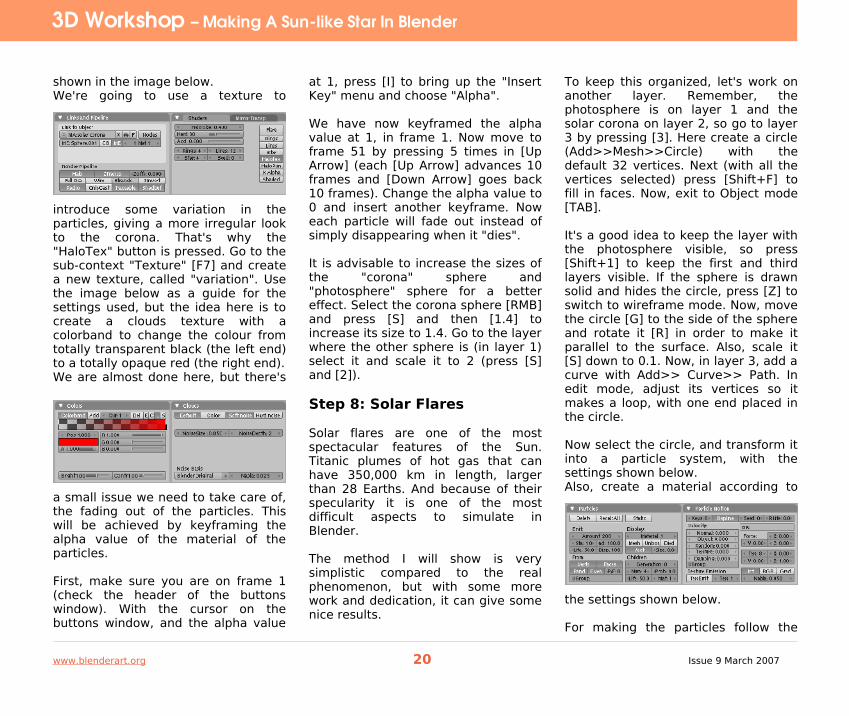
First, make sure you are on frame 1 (check the header of the buttons window). With the cursor on the buttons window, and the alpha value
at 1, press [I] to bring up the "Insert Key" menu and choose "Alpha".
We have now keyframed the alpha value at 1, in frame 1. Now move to frame 51 by pressing 5 times in [Up Arrow] (each [Up Arrow] advances 10 frames and [Down Arrow] goes back 10 frames). Change the alpha value to 0 and insert another keyframe. Now each particle will fade out instead of simply disappearing when it "dies".
It is advisable to increase the sizes of the "corona" sphere and "photosphere" sphere for a better effect. Select the corona sphere [RMB] and press [S] and then [1.4] to increase its size to 1.4. Go to the layer where the other sphere is (in layer 1) select it and scale it to 2 (press [S] and [2]).
Step 8: Solar Flares
Solar flares are one of the most spectacular features of the Sun. Titanic plumes of hot gas that can have 350,000 km in length, larger than 28 Earths. And because of their specularity it is one of the most difficult aspects to simulate in Blender.
The method I will show is very simplistic compared to the real phenomenon, but with some more work and dedication, it can give some nice results.
To keep this organized, let's work on another layer. Remember, the photosphere is on layer 1 and the solar corona on layer 2, so go to layer 3 by pressing [3]. Here create a circle (Add>>Mesh>>Circle) with the default 32 vertices. Next (with all the vertices selected) press [Shift+F] to fill in faces. Now, exit to Object mode [TAB].
It's a good idea to keep the layer with the photosphere visible, so press [Shift+1] to keep the first and third layers visible. If the sphere is drawn solid and hides the circle, press [Z] to switch to wireframe mode. Now, move the circle [G] to the side of the sphere and rotate it [R] in order to make it parallel to the surface. Also, scale it [S] down to 0.1. Now, in layer 3, add a curve with Add>> Curve>> Path. In edit mode, adjust its vertices so it makes a loop, with one end placed in the circle.
Now select the circle, and transform it into a particle system, with the settings shown below.Also, create a material according to
the settings shown below.
For making the particles follow the
www.blenderart.org 20 Issue 9 March 2007
3D Workshop – Making A Sun-like Star In Blender
curve, we must select it and go the buttons window, in context "Object"
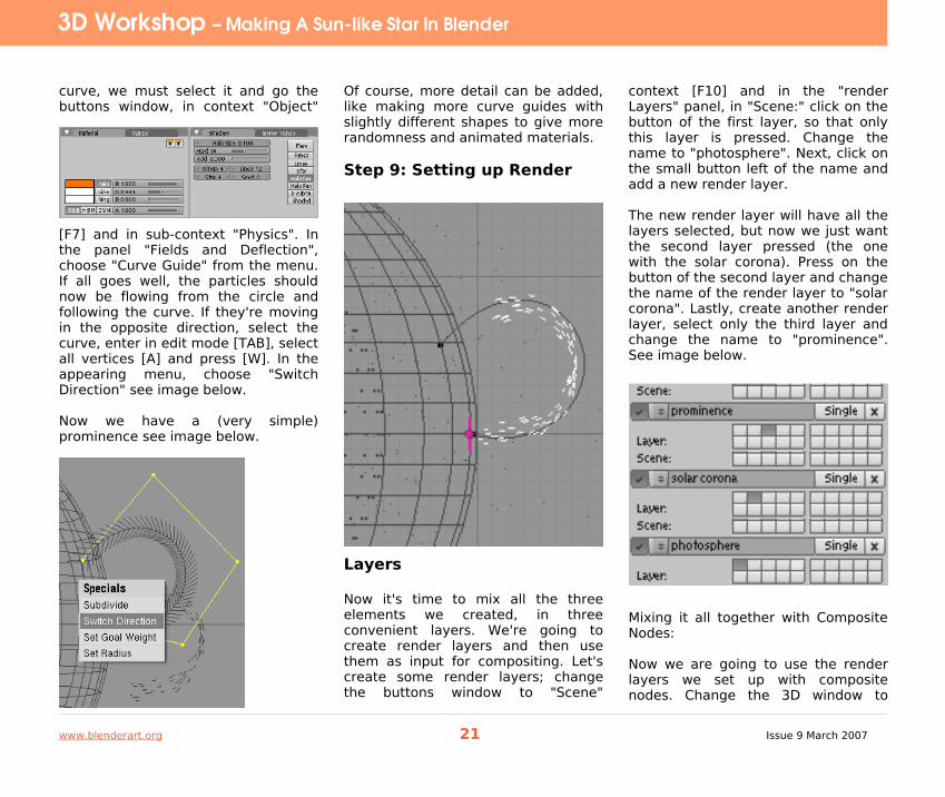
[F7] and in sub-context "Physics". In the panel "Fields and Deflection", choose "Curve Guide" from the menu. If all goes well, the particles should now be flowing from the circle and following the curve. If they're moving in the opposite direction, select the curve, enter in edit mode [TAB], select all vertices [A] and press [W]. In the appearing menu, choose "Switch Direction" see image below.
Now we have a (very simple) prominence see image below.
Of course, more detail can be added, like making more curve guides with slightly different shapes to give more randomness and animated materials.
Step 9: Setting up Render
Layers
Now it's time to mix all the three elements we created, in three convenient layers. We're going to create render layers and then use them as input for compositing. Let's create some render layers; change the buttons window to "Scene"
context [F10] and in the "render Layers" panel, in "Scene:" click on the button of the first layer, so that only this layer is pressed. Change the name to "photosphere". Next, click on the small button left of the name and add a new render layer.
The new render layer will have all the layers selected, but now we just want the second layer pressed (the one with the solar corona). Press on the button of the second layer and change the name of the render layer to "solar corona". Lastly, create another render layer, select only the third layer and change the name to "prominence". See image below.
Mixing it all together with Composite Nodes:
Now we are going to use the render layers we set up with composite nodes. Change the 3D window to
www.blenderart.org 21 Issue 9 March 2007
3D Workshop – Making A Sun-like Star In Blender
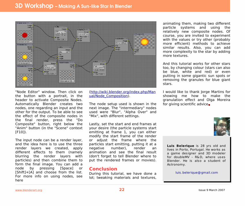
"Node Editor" window. Then click on the button with a portrait, in the header to activate Composite Nodes. Automatically Blender creates two nodes, one regarding an input and the other for the output. To be able to see the effect of the composite nodes in the final render, press the "Do Composite" button, right below the "Anim" button (in the "Scene" context [F10]).
The input node can be a render layer, and the idea here is to use the three render layers we created, apply different effects to them (namely blurring the render layers with particles) and then combine them to form the final image. You can add a node by pressing [Space] or [Shift]+[A] and choose from the list. For more info on using nodes, see here
(http://wiki.blender.org/index.php/Manual/Node_Composition).
The node setup used is shown in the next image. The "intermediary" nodes used were "Blur", "Alpha Over" and "Mix", with different settings.
Lastly, set the start and end frames at your desire (the particle systems start emitting at frame 1, you can either modify the start frame of the render or adjust the frame where the particles start emitting, putting it at a negative number), render an animation and see the final result (don't forget to tell Blender where to put the rendered frames or movies).
ConclusionDuring this tutorial, we have done a lot; tweaking materials and textures,
animating them, making two different particle systems and using the relatively new composite nodes. Of course, you are invited to experiment with the values or try other (probably more efficient) methods to achieve similar results. Also, you can add more complexity to the star by adding more textures.
And this tutorial works for other stars too, by changing colour (stars can also be blue, white and red) or even putting in some gigantic sun spots or removing the granules for blue giant stars.
I would like to thank Jorge Martins for showing me how to make the granulation effect and Olga Moreira for giving scientific advice■
www.blenderart.org 22 Issue 9 March 2007
Luis Belerique is 28 yrs old and lives in Porto, Portugal. He works as a game des igner and 3D modeler for doubleMV - R&D, where uses Blender. He is also a s tudent of As tronomy.
luis [email protected]
3D Workshop – Making A Sun-like Star In Blender
by Tim Kennedy for NEVAC
Level: Beginner to Intermediate
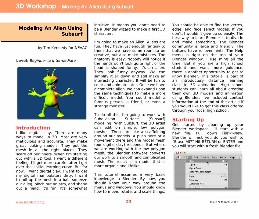
IntroductionI like digital clay. There are many ways to model in 3D. Most are very meticulous and accurate. They make great looking models. They put the mesh in all the right places. They scare off beginners. When I’m starting out with a 3D tool, I want a different feeling. I’ll get more careful after I get over that initial learning curve. But for now, I want digital clay. I want to get my digital manipulators dirty. I want to roll up the mesh in a ball, squeeze out a leg, pinch out an arm, and shape out a head. It’s fun. It’s somewhat
intuitive. It means you don’t need to be a Blender wizard to make a first 3D character.
I’m going to make an Alien. Aliens are fun. They have just enough fantasy to them that we have some room to be creative, but also make mistakes. The anatomy is easy. Nobody will notice if the hands don’t look quite right or the head is shaped funny. It’s an alien. They look funny anyway. We can simplify it all down and still make an interesting character. It will be fun to color and animate later. Once we have a complete alien, we can expand upon the same techniques to make a more difficult model. You could model a famous person, a friend, or even a strange monster.
To do all this, I’m going to work with Subdivision Surface (Subsurf) modeling. With Subsurf, the 3D artist can edit on simple, low polygon meshes. These are like a scaffolding around our models. A push here or a movement there and the model mesh (our digital clay) responds. But where we are working with the low polygon mesh, the Blender software converts our work to a smooth and complicated mesh. The result is a model that is more organic and lifelike.
This tutorial assumes a very basic knowledge in Blender. By now, you should know your way around the menus and windows. You should know how to move, rotate, and scale things.
You should be able to find the vertex, edge, and face select modes. If you don’t, I wouldn’t give up so easily. The best way to learn Blender is to dive in and make something. The Blender community is large and friendly. The buttons have rollover hints. The Help menu is right on the top of your Blender window. I use mine all the time. But if you are a high school student and want more guidance, there is another opportunity to get to know Blender. This tutorial is part of an introductory distance learning class in 3D animation. High school students can learn all about creating their own 3D models and animation using Blender. I’ve included contact information at the end of the article if you would like to get this class offered through your local high school.
Starting UpGet started by cleaning up your Blender workspace. I’ll start with a new file. Pull down File>>New. Blender will ask you do you wish to “Erase All?” Hit RETURN or ENTER and you will start with a fresh Blender file.
www.blenderart.org 23 Issue 9 March 2007
Modeling An Alien Using Subsurf
3D Workshop – Making An Alien Using Subsurf
Step 1: Reference Images
Reference images guide the 3D artist in the creation of the model. You can build great models without reference images. I think it is easier to build great models with them.
So how are your drawing skills? Mine are OK. I’m not the world’s best artist. But I can comfortably draw an idea on a piece of paper. Drawing is an important skill for a 3D artist. You can doodle out an idea in the morning and have a finished model by the end of the day. That’s hard to do if you are just making it up as you go in your 3D software. So if you haven’t taken drawing classes, I would encourage you to do so. Even if you never work as a professional 3D artist, being able to communicate any idea with a quick drawing is a skill that will help you later in life.
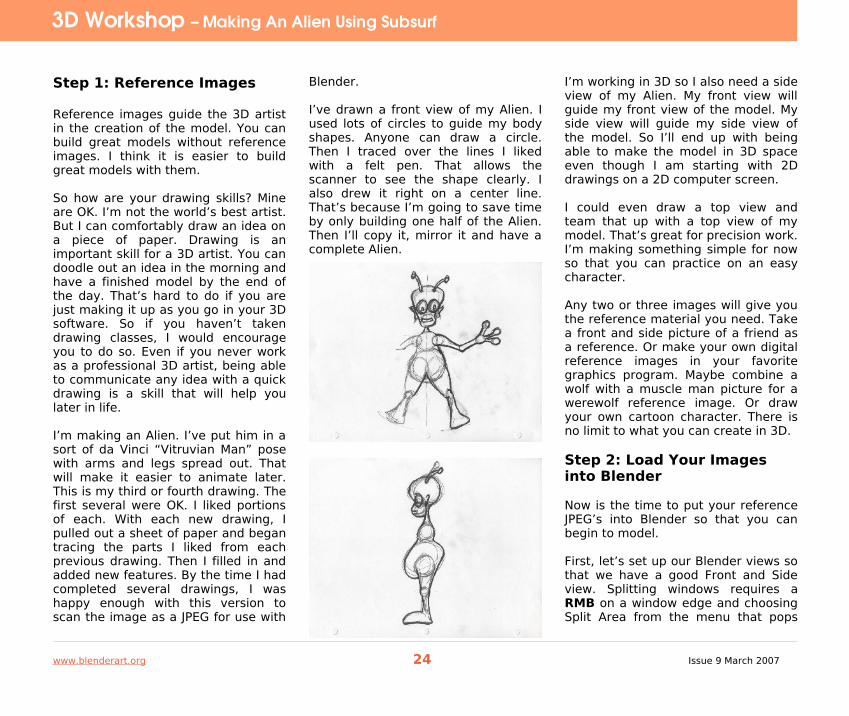
I’m making an Alien. I’ve put him in a sort of da Vinci “Vitruvian Man” pose with arms and legs spread out. That will make it easier to animate later. This is my third or fourth drawing. The first several were OK. I liked portions of each. With each new drawing, I pulled out a sheet of paper and began tracing the parts I liked from each previous drawing. Then I filled in and added new features. By the time I had completed several drawings, I was happy enough with this version to scan the image as a JPEG for use with
Blender.
I’ve drawn a front view of my Alien. I used lots of circles to guide my body shapes. Anyone can draw a circle. Then I traced over the lines I liked with a felt pen. That allows the scanner to see the shape clearly. I also drew it right on a center line. That’s because I’m going to save time by only building one half of the Alien. Then I’ll copy it, mirror it and have a complete Alien.
I’m working in 3D so I also need a side view of my Alien. My front view will guide my front view of the model. My side view will guide my side view of the model. So I’ll end up with being able to make the model in 3D space even though I am starting with 2D drawings on a 2D computer screen.
I could even draw a top view and team that up with a top view of my model. That’s great for precision work. I’m making something simple for now so that you can practice on an easy character.
Any two or three images will give you the reference material you need. Take a front and side picture of a friend as a reference. Or make your own digital reference images in your favorite graphics program. Maybe combine a wolf with a muscle man picture for a werewolf reference image. Or draw your own cartoon character. There is no limit to what you can create in 3D.
Step 2: Load Your Images into Blender
Now is the time to put your reference JPEG’s into Blender so that you can begin to model.
First, let’s set up our Blender views so that we have a good Front and Side view. Splitting windows requires a RMB on a window edge and choosing Split Area from the menu that pops
www.blenderart.org 24 Issue 9 March 2007
3D Workshop – Making An Alien Using Subsurf
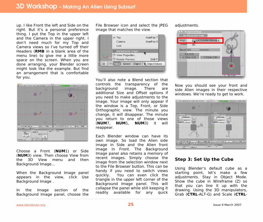
up. I like Front the left and Side on the right. But it’s a personal preference thing. I put the Top in the upper left and the Camera in the upper right. I don’t need much for my Top and Camera views so I’ve turned off their Headers (RMB in a blank area of the menu line) to give me a little more space on the screen. When you are done arranging, your Blender screen might look like the example. But find an arrangement that is comfortable for you.
Choose a Front (NUM1) or Side (NUM3) view. Then choose View from the 3D View menu and then Background Image...
When the Background Image panel appears in the view, click Use Background Image .
In the Image section of the Background Image panel, choose the
File Browser icon and select the JPEG image that matches the view.
You’ll also note a Blend section that controls the transparency of the background image. There are additional Size and Offset options if you need to make adjustments to the image. Your image will only appear if the window is a Top, Front, or Side Orthographic view. The minute you change, it will disappear. The minute you return to one of those views (NUM7, NUM1, NUM3) it will reappear.
Each Blender window can have its own image. So load the Alien side image in Side and the Alien front image in Front. The Background Image panel also retains a memory of recent images. Simply choose the image from the selection window next to the File Browser button. This can be handy if you need to switch views quickly. You can even click the triangle in the upper left corner of the Background Image panel. This will collapse the panel while still keeping it readily available for any quick
adjustments.
Now you should see your front and side Alien images in their respective windows. We’re ready to get to work.
Step 3: Set Up the Cube
Using Blender’s default cube as a starting point, let’s make a few adjustments. Stay in Object Mode. Show the cube in Wireframe (Z) so that you can line it up with the drawing. Using the 3D manipulators, Grab (CTRL-ALT-G) and Scale (CTRL-
www.blenderart.org 25 Issue 9 March 2007
3D Workshop – Making An Alien Using Subsurf
ALT-S) the cube so that it fits the belly area. You can have a little inside and a little outside. We’ll reshape it into place.
Notice that I have SHIFT-LMB selected the Translate (Grab) and Scale manipulator widgets so that I can use both in the same window at the same time. This approach gets even handier later. Also remember that each window can have its own choice of manipulator.
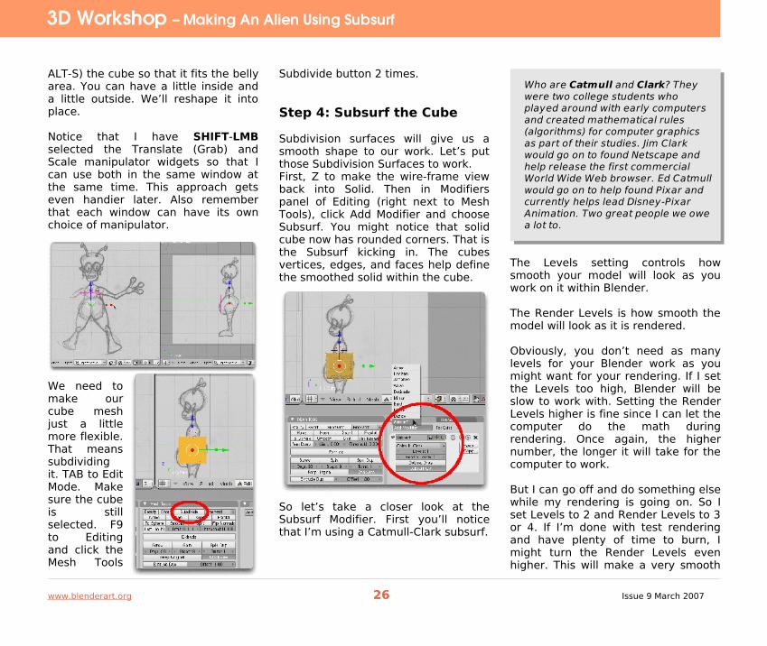
We need to make our cube mesh just a little more flexible. That means subdividing it. TAB to Edit Mode. Make sure the cube is still selected. F9 to Editing and click the Mesh Tools
Subdivide button 2 times.
Step 4: Subsurf the Cube
Subdivision surfaces will give us a smooth shape to our work. Let’s put those Subdivision Surfaces to work. First, Z to make the wire-frame view back into Solid. Then in Modifiers panel of Editing (right next to Mesh Tools), click Add Modifier and choose Subsurf. You might notice that solid cube now has rounded corners. That is the Subsurf kicking in. The cubes vertices, edges, and faces help define the smoothed solid within the cube.
So let’s take a closer look at the Subsurf Modifier. First you’ll notice that I’m using a Catmull-Clark subsurf.
The Levels setting controls how smooth your model will look as you work on it within Blender.
The Render Levels is how smooth the model will look as it is rendered.
Obviously, you don’t need as many levels for your Blender work as you might want for your rendering. If I set the Levels too high, Blender will be slow to work with. Setting the Render Levels higher is fine since I can let the computer do the math during rendering. Once again, the higher number, the longer it will take for the computer to work.
But I can go off and do something else while my rendering is going on. So I set Levels to 2 and Render Levels to 3 or 4. If I’m done with test rendering and have plenty of time to burn, I might turn the Render Levels even higher. This will make a very smooth
www.blenderart.org 26 Issue 9 March 2007
Who are Catmull and Clark? They were two college students who played around with early computers and created mathematical rules (algorithms) for computer graphics as part of their studies. Jim Clark would go on to found Netscape and help release the first commercial World Wide Web browser. Ed Catmull would go on to help found Pixar and currently helps lead Disney-Pixar Animation. Two great people we owe a lot to.
3D Workshop – Making An Alien Using Subsurf
model. Just realize that this will slow the computer down and too much will go unseen for all your wasted computer time.
There is a little gray circle to the right of the Subsurf title in the Modifiers panel. Subsurf modeling involves editing the low polygon cage while letting the Catmull-Clark do the math on your model behind the scenes. Clicking that little grey circle will Apply Modifier to the Editing Cage. That means the cage will cling to the surface. Click the circle on and off and you’ll see the subtle result on your model in the window. We’ll see this in use later. It’s a preference that may or may not make editing easier as you work on your model. Sometimes it is easier with it off. Sometimes it is easier with it on.
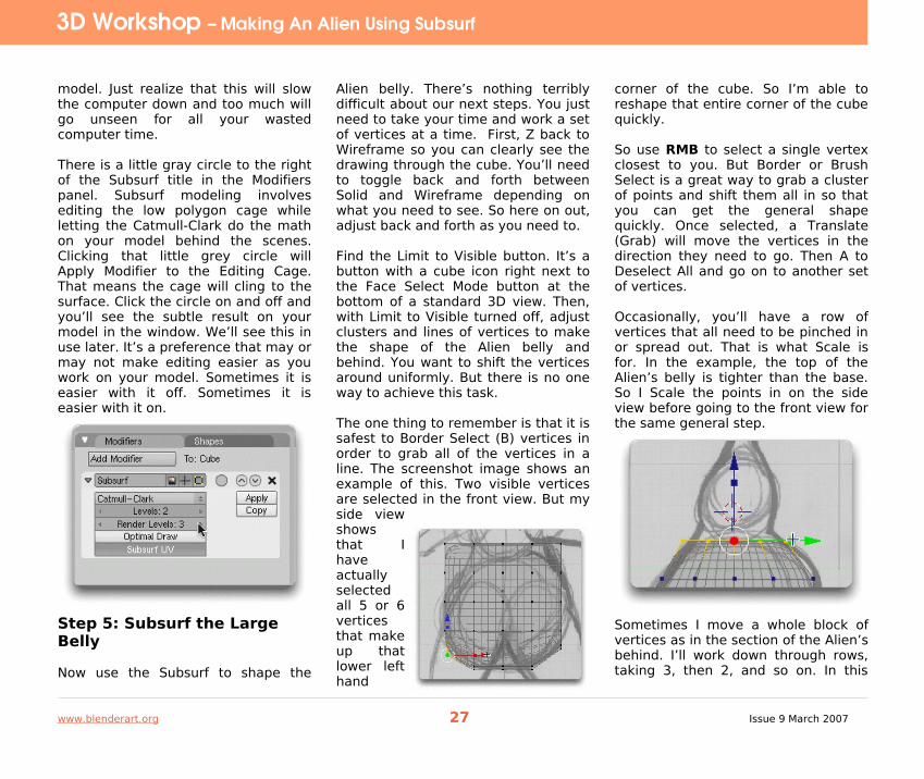
Step 5: Subsurf the Large Belly
Now use the Subsurf to shape the
Alien belly. There’s nothing terribly difficult about our next steps. You just need to take your time and work a set of vertices at a time. First, Z back to Wireframe so you can clearly see the drawing through the cube. You’ll need to toggle back and forth between Solid and Wireframe depending on what you need to see. So here on out, adjust back and forth as you need to.
Find the Limit to Visible button. It’s a button with a cube icon right next to the Face Select Mode button at the bottom of a standard 3D view. Then, with Limit to Visible turned off, adjust clusters and lines of vertices to make the shape of the Alien belly and behind. You want to shift the vertices around uniformly. But there is no one way to achieve this task.
The one thing to remember is that it is safest to Border Select (B) vertices in order to grab all of the vertices in a line. The screenshot image shows an example of this. Two visible vertices are selected in the front view. But my side view shows that I have actually selected all 5 or 6 vertices that make up that lower left hand
corner of the cube. So I’m able to reshape that entire corner of the cube quickly.
So use RMB to select a single vertex closest to you. But Border or Brush Select is a great way to grab a cluster of points and shift them all in so that you can get the general shape quickly. Once selected, a Translate (Grab) will move the vertices in the direction they need to go. Then A to Deselect All and go on to another set of vertices.
Occasionally, you’ll have a row of vertices that all need to be pinched in or spread out. That is what Scale is for. In the example, the top of the Alien’s belly is tighter than the base. So I Scale the points in on the side view before going to the front view for the same general step.
Sometimes I move a whole block of vertices as in the section of the Alien’s behind. I’ll work down through rows, taking 3, then 2, and so on. In this
www.blenderart.org 27 Issue 9 March 2007
3D Workshop – Making An Alien Using Subsurf
way, I can keep my vertices somewhat uniformly spread out. I don’t want vertices all bunching up or I will not be able to get the right shape later.
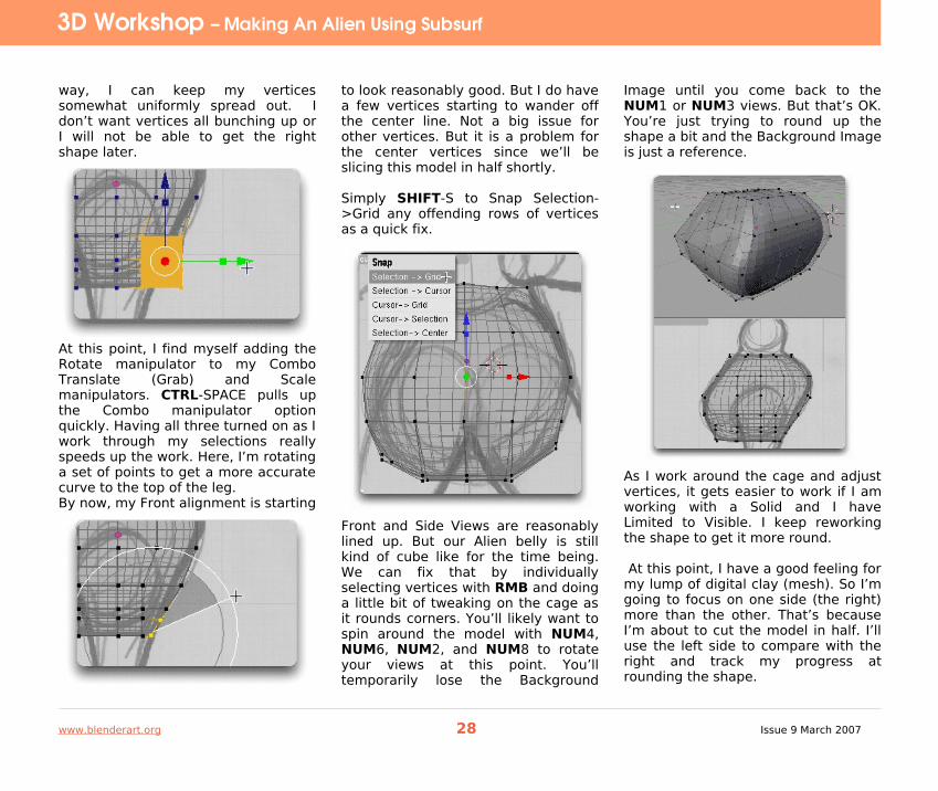
At this point, I find myself adding the Rotate manipulator to my Combo Translate (Grab) and Scale manipulators. CTRL-SPACE pulls up the Combo manipulator option quickly. Having all three turned on as I work through my selections really speeds up the work. Here, I’m rotating a set of points to get a more accurate curve to the top of the leg. By now, my Front alignment is starting
to look reasonably good. But I do have a few vertices starting to wander off the center line. Not a big issue for other vertices. But it is a problem for the center vertices since we’ll be slicing this model in half shortly.
Simply SHIFT-S to Snap Selection->Grid any offending rows of vertices as a quick fix.
Front and Side Views are reasonably lined up. But our Alien belly is still kind of cube like for the time being. We can fix that by individually selecting vertices with RMB and doing a little bit of tweaking on the cage as it rounds corners. You’ll likely want to spin around the model with NUM4, NUM6, NUM2, and NUM8 to rotate your views at this point. You’ll temporarily lose the Background
Image until you come back to the NUM1 or NUM3 views. But that’s OK. You’re just trying to round up the shape a bit and the Background Image is just a reference.
As I work around the cage and adjust vertices, it gets easier to work if I am working with a Solid and I have Limited to Visible. I keep reworking the shape to get it more round.
At this point, I have a good feeling for my lump of digital clay (mesh). So I’m going to focus on one side (the right) more than the other. That’s because I’m about to cut the model in half. I’ll use the left side to compare with the right and track my progress at rounding the shape.
www.blenderart.org 28 Issue 9 March 2007
3D Workshop – Making An Alien Using Subsurf
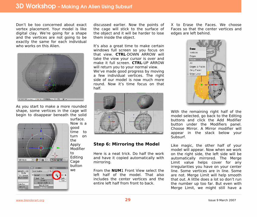
Don’t be too concerned about exact vertex placement. Your model is like digital clay. We’re going for a shape and the vertices are not going to be exactly the same for each individual who works on this Alien.
As you start to make a more rounded shape, some vertices in the cage will begin to disappear beneath the solid
surface. Now is a good time to turn on the Apply Modifier to Editing Cage button we
discussed earlier. Now the points of the cage will stick to the surface of the object and it will be harder to lose them inside the object. It’s also a great time to make certain windows full screen so you focus on that view. CTRL-DOWN ARROW will take the view your cursor is over and make it full screen. CTRL-UP ARROW will return you to your normal view. We’ve made good progress by moving a few individual vertices. The right side of our model is now much more round. Now it’s time focus on that half.
Step 6: Mirroring the Model Here is a neat trick. Do half the work and have it copied automatically with mirroring.
From the NUM1 Front View select the left half of the model. That also includes the center vertices and the entire left half from front to back.
X to Erase the Faces. We choose Faces so that the center vertices and edges are left behind.
With the remaining right half of the model selected, go back to the Editing buttons and click the Add Modifier button under the Modifiers panel. Choose Mirror. A Mirror modifier will appear in the stack below your Subsurf.
Like magic, the other half of your model will appear. Now when we work on the right side, the left side will be automatically mirrored. The Merge Limit value helps cover for any irregularities you have on your center line. Some vertices are in line. Some are not. Merge Limit will help smooth that out. A little does a lot so don’t run the number up too far. But even with Merge Limit, we might still have a
www.blenderart.org 29 Issue 9 March 2007
3D Workshop – Making An Alien Using Subsurf
little seam in our model until we finish
and smooth it out for good.
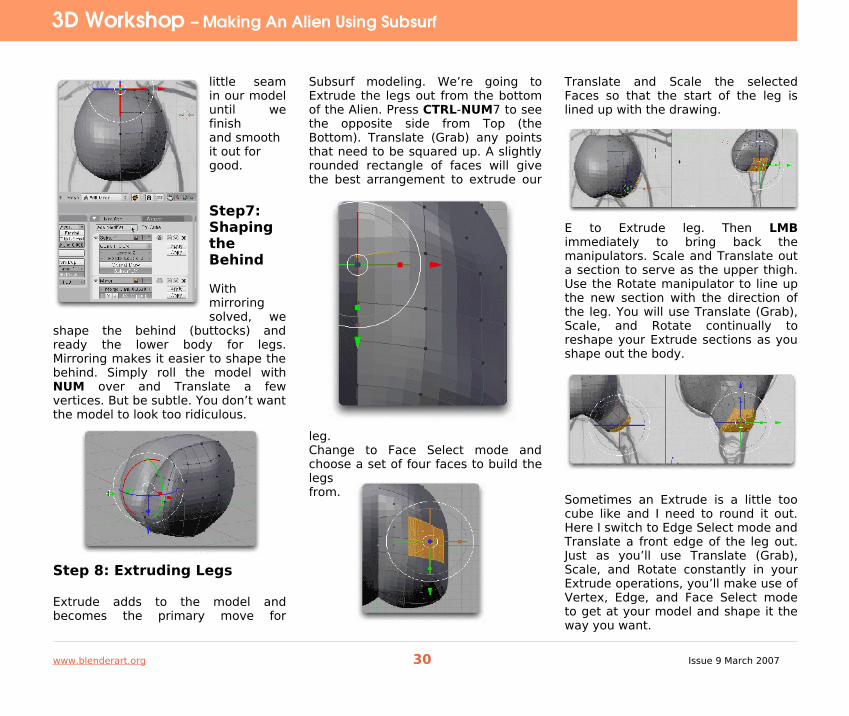
Step7: Shaping the Behind
With mirroring solved, we
shape the behind (buttocks) and ready the lower body for legs. Mirroring makes it easier to shape the behind. Simply roll the model with NUM over and Translate a few vertices. But be subtle. You don’t want the model to look too ridiculous.
Step 8: Extruding Legs
Extrude adds to the model and becomes the primary move for
Subsurf modeling. We’re going to Extrude the legs out from the bottom of the Alien. Press CTRL-NUM7 to see the opposite side from Top (the Bottom). Translate (Grab) any points that need to be squared up. A slightly rounded rectangle of faces will give the best arrangement to extrude our
leg. Change to Face Select mode and choose a set of four faces to build the legs from.
Translate and Scale the selected Faces so that the start of the leg is lined up with the drawing.
E to Extrude leg. Then LMB immediately to bring back the manipulators. Scale and Translate out a section to serve as the upper thigh. Use the Rotate manipulator to line up the new section with the direction of the leg. You will use Translate (Grab), Scale, and Rotate continually to reshape your Extrude sections as you shape out the body.
Sometimes an Extrude is a little too cube like and I need to round it out. Here I switch to Edge Select mode and Translate a front edge of the leg out. Just as you’ll use Translate (Grab), Scale, and Rotate constantly in your Extrude operations, you’ll make use of Vertex, Edge, and Face Select mode to get at your model and shape it the way you want.
www.blenderart.org 30 Issue 9 March 2007
3D Workshop – Making An Alien Using Subsurf
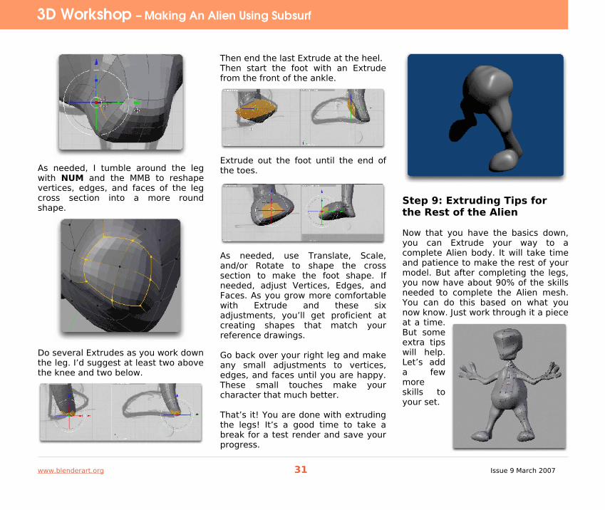
As needed, I tumble around the leg with NUM and the MMB to reshape vertices, edges, and faces of the leg cross section into a more round shape.
Do several Extrudes as you work down the leg. I’d suggest at least two above the knee and two below.
Then end the last Extrude at the heel. Then start the foot with an Extrude from the front of the ankle.
Extrude out the foot until the end of the toes.
As needed, use Translate, Scale, and/or Rotate to shape the cross section to make the foot shape. If needed, adjust Vertices, Edges, and Faces. As you grow more comfortable with Extrude and these six adjustments, you’ll get proficient at creating shapes that match your reference drawings.
Go back over your right leg and make any small adjustments to vertices, edges, and faces until you are happy. These small touches make your character that much better.
That’s it! You are done with extruding the legs! It’s a good time to take a break for a test render and save your progress.
Step 9: Extruding Tips for the Rest of the Alien
Now that you have the basics down, you can Extrude your way to a complete Alien body. It will take time and patience to make the rest of your model. But after completing the legs, you now have about 90% of the skills needed to complete the Alien mesh. You can do this based on what you now know. Just work through it a piece at a time. But some extra tips will help. Let’s add a few more skills to your set.
www.blenderart.org 31 Issue 9 March 2007
3D Workshop – Making An Alien Using Subsurf
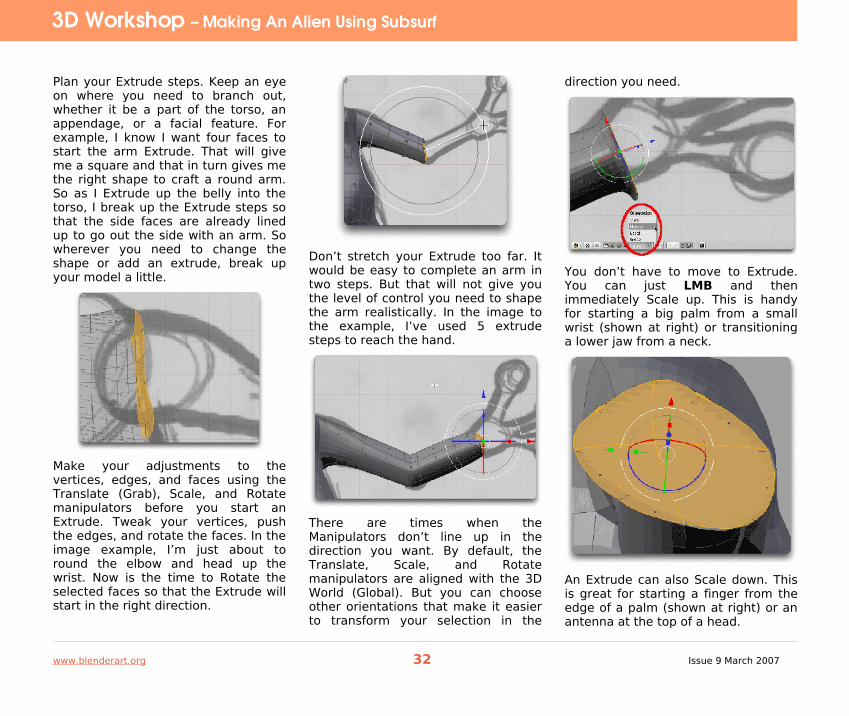
Plan your Extrude steps. Keep an eye on where you need to branch out, whether it be a part of the torso, an appendage, or a facial feature. For example, I know I want four faces to start the arm Extrude. That will give me a square and that in turn gives me the right shape to craft a round arm. So as I Extrude up the belly into the torso, I break up the Extrude steps so that the side faces are already lined up to go out the side with an arm. So wherever you need to change the shape or add an extrude, break up your model a little.
Make your adjustments to the vertices, edges, and faces using the Translate (Grab), Scale, and Rotate manipulators before you start an Extrude. Tweak your vertices, push the edges, and rotate the faces. In the image example, I’m just about to round the elbow and head up the wrist. Now is the time to Rotate the selected faces so that the Extrude will start in the right direction.
Don’t stretch your Extrude too far. It would be easy to complete an arm in two steps. But that will not give you the level of control you need to shape the arm realistically. In the image to the example, I’ve used 5 extrude steps to reach the hand.
There are times when the Manipulators don’t line up in the direction you want. By default, the Translate, Scale, and Rotate manipulators are aligned with the 3D World (Global). But you can choose other orientations that make it easier to transform your selection in the
direction you need.
You don’t have to move to Extrude. You can just LMB and then immediately Scale up. This is handy for starting a big palm from a small wrist (shown at right) or transitioning a lower jaw from a neck.
An Extrude can also Scale down. This is great for starting a finger from the edge of a palm (shown at right) or an antenna at the top of a head.
www.blenderart.org 32 Issue 9 March 2007
3D Workshop – Making An Alien Using Subsurf
Finally, you don’t have to model everything with Extrude. I only want the basic body shape, the head, the arms with hands, and the feet. I’ll leave other details like the eyes and mouth for later. They’ll be easier to create with other primitives and extrude steps later on. I can even use Blender’s new Sculpt Mode to add finer detail or modify my base shape.
I also leave some details out for when the model is complete. Why? No one organic character should be identical on both sides of the body. If I add details, now, they’ll be copied exactly to the other side. By adding some details after I have a complete model, I guarantee that there will be some differences between the
left and right side of the model. That will make it more true to life.
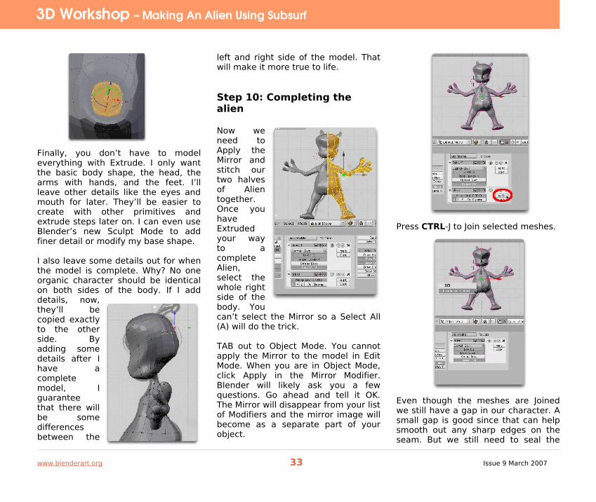
Step 10: Completing the alien
Now we need to Apply the Mirror and stitch our two halves of Alien together. Once you have Extruded your way to a complete Alien, select the whole right side of the body. You can’t select the Mirror so a Select All (A) will do the trick.
TAB out to Object Mode. You cannot apply the Mirror to the model in Edit Mode. When you are in Object Mode, click Apply in the Mirror Modifier. Blender will likely ask you a few questions. Go ahead and tell it OK. The Mirror will disappear from your list of Modifiers and the mirror image will become as a separate part of your object.
Press CTRL-J to Join selected meshes.
Even though the meshes are Joined we still have a gap in our character. A small gap is good since that can help smooth out any sharp edges on the seam. But we still need to seal the
www.blenderart.org 33 Issue 9 March 2007
3D Workshop – Making An Alien Using Subsurf
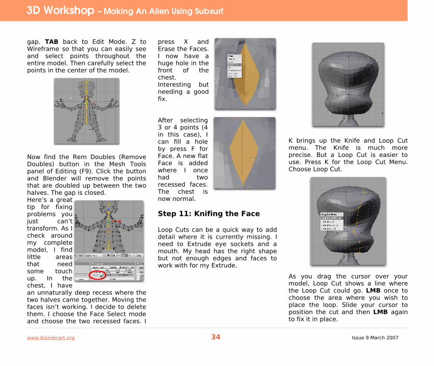
gap. TAB back to Edit Mode. Z to Wireframe so that you can easily see and select points throughout the entire model. Then carefully select the points in the center of the model.
Now find the Rem Doubles (Remove Doubles) button in the Mesh Tools panel of Editing (F9). Click the button and Blender will remove the points that are doubled up between the two halves. The gap is closed. Here’s a great tip for fixing problems you just can’t transform. As I check around my complete model, I find little areas that need some touch up. In the chest, I have an unnaturally deep recess where the two halves came together. Moving the faces isn’t working. I decide to delete them. I choose the Face Select mode and choose the two recessed faces. I
press X and Erase the Faces. I now have a huge hole in the front of the chest. Interesting but needing a good fix.
After selecting 3 or 4 points (4 in this case), I can fill a hole by press F for Face. A new flat Face is added where I once had two recessed faces. The chest is now normal.
Step 11: Knifing the Face
Loop Cuts can be a quick way to add detail where it is currently missing. I need to Extrude eye sockets and a mouth. My head has the right shape but not enough edges and faces to work with for my Extrude.
K brings up the Knife and Loop Cut menu. The Knife is much more precise. But a Loop Cut is easier to use. Press K for the Loop Cut Menu. Choose Loop Cut.
As you drag the cursor over your model, Loop Cut shows a line where the Loop Cut could go. LMB once to choose the area where you wish to place the loop. Slide your cursor to position the cut and then LMB again to fix it in place.
www.blenderart.org 34 Issue 9 March 2007
3D Workshop – Making An Alien Using Subsurf
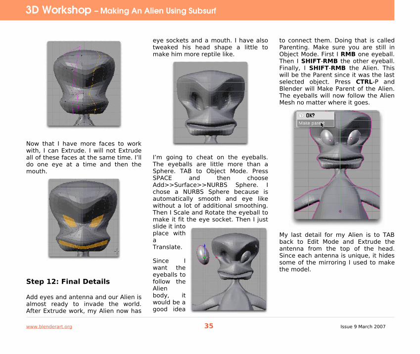
Now that I have more faces to work with, I can Extrude. I will not Extrude all of these faces at the same time. I’ll do one eye at a time and then the mouth.
Step 12: Final Details
Add eyes and antenna and our Alien is almost ready to invade the world. After Extrude work, my Alien now has
eye sockets and a mouth. I have also tweaked his head shape a little to make him more reptile like.
I’m going to cheat on the eyeballs. The eyeballs are little more than a Sphere. TAB to Object Mode. Press SPACE and then choose Add>>Surface>>NURBS Sphere. I chose a NURBS Sphere because is automatically smooth and eye like without a lot of additional smoothing. Then I Scale and Rotate the eyeball to make it fit the eye socket. Then I just slide it into place with a Translate.
Since I want the eyeballs to follow the Alien body, it would be a good idea
to connect them. Doing that is called Parenting. Make sure you are still in Object Mode. First I RMB one eyeball. Then I SHIFT-RMB the other eyeball. Finally, I SHIFT-RMB the Alien. This will be the Parent since it was the last selected object. Press CTRL-P and Blender will Make Parent of the Alien. The eyeballs will now follow the Alien Mesh no matter where it goes.
My last detail for my Alien is to TAB back to Edit Mode and Extrude the antenna from the top of the head. Since each antenna is unique, it hides some of the mirroring I used to make the model.
www.blenderart.org 35 Issue 9 March 2007
3D Workshop – Making An Alien Using Subsurf
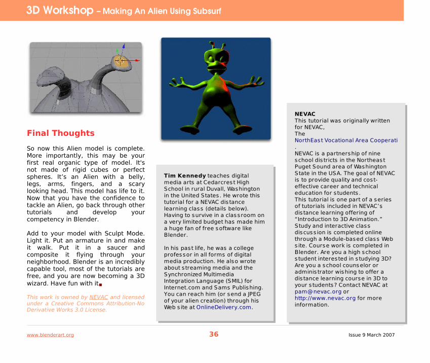
Final Thoughts
So now this Alien model is complete. More importantly, this may be your first real organic type of model. It's not made of rigid cubes or perfect spheres. It’s an Alien with a belly, legs, arms, fingers, and a scary looking head. This model has life to it. Now that you have the confidence to tackle an Alien, go back through other tutorials and develop your competency in Blender.
Add to your model with Sculpt Mode. Light it. Put an armature in and make it walk. Put it in a saucer and composite it flying through your neighborhood. Blender is an incredibly capable tool, most of the tutorials are free, and you are now becoming a 3D wizard. Have fun with it■
This work is owned by NEVAC and licensed under a Creative Commons Attribution-No Derivative Works 3.0 License.
www.blenderart.org 36 Issue 9 March 2007
3D Workshop – Making An Alien Using Subsurf
Tim Kennedy teaches digital media arts at Cedarcres t High School in rural Duvall, Washington in the United States . He wrote this tutorial for a NEVAC dis tance learning class (details below). Having to survive in a classroom on a very limited budget has made him a huge fan of free software like Blender.
In his past life, he was a college professor in all forms of digital media production. He also wrote about s treaming media and the Synchronized Multimedia Integration Language (SMIL) for Internet.com and Sams Publishing. You can reach him (or send a JPEG of your alien creation) through his Web s ite at OnlineDelivery.com.
NEVACThis tutorial was originally written for NEVAC,The NorthEast Vocational Area Cooperative.NEVAC is a partnership of nine school dis tricts in the Northeas t Puget Sound area of Washington State in the USA. The goal of NEVAC is to provide quality and cost-effective career and technical education for s tudents . This tutorial is one part of a series of tutorials included in NEVAC’s dis tance learning offering of “Introduction to 3D Animation.” Study and interactive class discuss ion is completed online through a Module-based class Web s ite. Course work is completed in Blender. Are you a high school s tudent interested in s tudying 3D? Are you a school counselor or adminis trator wishing to offer a dis tance learning course in 3D to your s tudents? Contact NEVAC at [email protected] or http://www.nevac.org for more information.
by Sandra Gilbert (dreamsgate)
Level: beginner to intermediate
IntroductionHaving used blender for over seven years, I have gotten very comfortable with the material panels and all their wonderful uses. So when Nodes were introduced, I have to admit, I had quite a bit of trouble seeing the advantage of using Nodes over what I already knew. I read all the documentation, checked out tutorials, and still didn’t get it.
In fact, the tutorial that sticks out the most had you make a blue material and a red material, and when you mixed them it made a purple material. That’s nice, but I can make purple without using Nodes. Then I saw a great video tutorial (Mixing Materials Using Texture Painting (with UV Unwrap)-Extended Edition) by Eugene on http://www.geneome.net.
He covered creating Mix Maps to blend two or more materials using Nodes. Finally I could see the advantage of using Nodes! This technique allows the smooth blending
of materials and has the added benefit, unlike painting a UV Map, of allowing you to quickly change the materials that are being blended.
So to that end, I am going to show you how to texture an alien using Nodes/Mix Map. I have already modeled an alien, albeit a rather odd looking fellow, for us to practice on. The “Texturing an Alien.blend” has four scenes, depending on where you want to jump into the tutorial.
• Alien: only contains the alien model – to follow the tutorial from the beginning
• Alien & UV Map – the alien already has the UV Map coordinates set up, so you can jump in at the 'Painting the Mix Map' section.
• Alien Nodes: Mix Maps are painted, so you can jump in at the 'Setting up Nodes' section
• Finished Alien – everything is done, this scene is to see the complete final setup
When you open Texturing an Alien.blend, you will notice that the model has a mirror modifier that has not yet been applied. I find it easier to UV Map one half of the model before applying the mirror modifier. That way both sides look the same.
Note: Having both sides look the same is not always desired, especially if creating a realistic model/object that has
asymmetrical texture details, but for our purposes this will save a lot of work and frustration.
Let’s get started: Mix Maps First thing we are going to do is set our UV Map coordinates. There are many ways to unwrap a model for UV Mapping and Blender has some great tools to get it done.
1. Go into UV Face Select Mode, split your screen, and change the right side to the UV Editor Window (fig 1)
2. Select all faces (A key) and hit “U key”, select Cylinder From View. You will need to resize the UV layout in the UV/Image Editor so that it fits in the screen. You will also want to scale it so that it no longer looks like a super skinny alien. (fig 2) This gives us a pretty good starting point for our UV map, but you will notice that the ears and the arms are not
www.blenderart.org 37 Issue 9 March 2007
3D Workshop – Texturing An Alien Using Nodes
Texturing An Alien Using Nodes
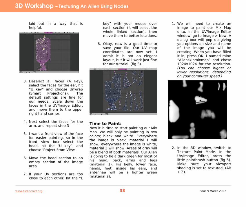
laid out in a way that is helpful.
3. Deselect all faces (A key), select the faces for the ear, hit “U key” and choose Unwrap (Smart Projections). The default settings are fine for our needs. Scale down the faces in the UV/Image Editor, and move them to the upper right hand corner.
4. Next select the faces for the arm, and repeat step 3
5. I want a front view of the face for easier painting, so in the front view box select the head, hit the “U key”, and choose 'Project From View'.
6. Move the head section to an empty section of the image area
7. If your UV sections are too close to each other, hit the “L
key” with your mouse over each section (it will select the whole linked section), then move them to better locations.
8. Okay, now is a good time to save your file. Our UV map coordinates are now set. I admit it is not an elegant layout, but it will work just fine for our tutorial. (fig 3).
Time to Paint: Now it is time to start painting our Mix Map. We will only be painting in two colors; black and white. Everywhere the image is black, material 1 will show; everywhere the image is white, material 2 will show. Areas of gray will be a blend of both materials. Our Alien is going to be a dark green for most of his head, back, arms and legs (material 1). His belly, lower face, hands, feet, inside his ears, and antennae will be a lighter green (material 2).
1. We will need to create an image to paint our Mix Map onto. In the UV/Image Editor window, go to Image > New. A dialog box will pop up giving you options on size and name of the image you will be creating. When you have filled it in, press OK. I named mine “Alienskinmixmap” and chose 1024x1024 for the resolution. (You can choose higher or lower resolutions, depending on your computer speed.)
2. In the 3D window, switch to Texture Paint Mode. In the UV/Image Editor, press the little paintbrush button (fig 5). Make sure your viewport shading is set to textured, (Alt + Z).
www.blenderart.org 38 Issue 9 March 2007
3D Workshop – Texturing An Alien Using Nodes
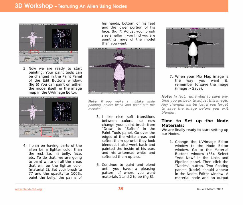
3. Now we are ready to start painting. Your paint tools can be changed in the Paint Panel of the Edit Buttons window. (fig 6) You can paint on either the model itself, or the image map in the UV/Image Editor.
4. I plan on having parts of the alien be a lighter color than the rest, i.e. his belly, face, etc. To do that, we are going to paint white on all the areas that will be the lighter color (material 2). Set your brush to 77 and the opacity to 100%, paint the belly, the palms of
his hands, bottom of his feet and the lower portion of his face. (fig 7) Adjust your brush size smaller if you find you are painting more of the model than you want.
Note: If you make a mistake while painting, select black and paint out the mistake.
5. I like nice soft transitions between colors, so now change your paint brush from “Draw” to “Soften” in the Paint Tools panel. Go over the edges of the white areas and soften them up until they look blended. I also went back and painted the inside of his ears and his antennae white and softened them up also.
6. Continue to paint and blend until you have a pleasing pattern of where you want materials 1 and 2 to be (fig 8).
7. When your Mix Map image is
the way you want it, remember to save the image (Image > Save).
Note: In fact, remember to save any time you go back to adjust this image. Any changes will be lost if you forget to save the image before you exit blender.
Time to Set up the Node Materials: We are finally ready to start setting up our Nodes.
1. Change the UV/Image Editor window to the Node Editor window. Go to the Material Buttons window (F5). Select “Add New” in the Links and Pipeline panel. Then click the “Nodes” button. Two floating panels (Node) should appear in the Nodes Editor window. A material node and an output
www.blenderart.org 39 Issue 9 March 2007
3D Workshop – Texturing An Alien Using Nodes
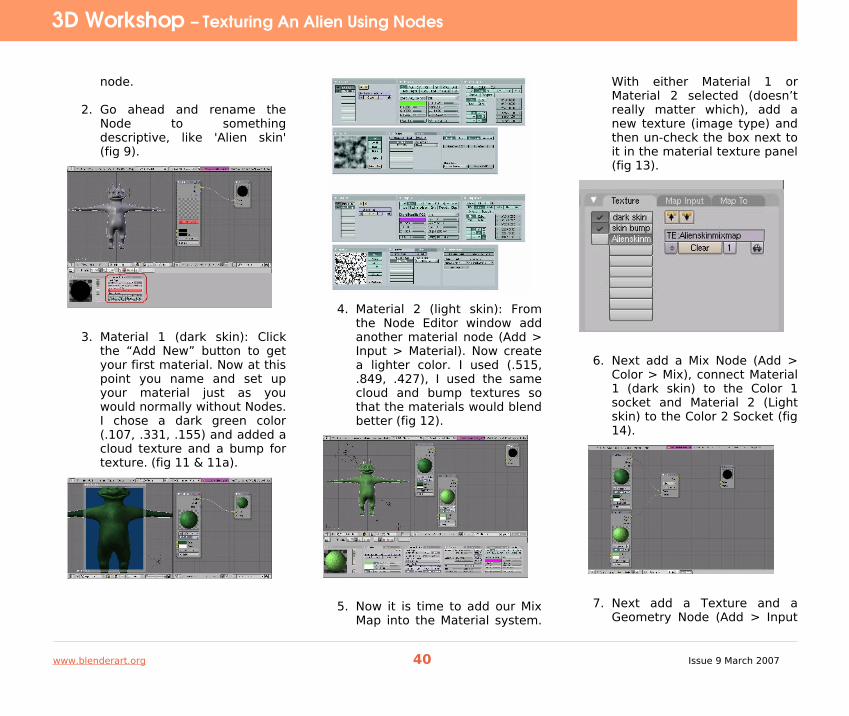
node.
2. Go ahead and rename the Node to something descriptive, like 'Alien skin' (fig 9).
3. Material 1 (dark skin): Click the “Add New” button to get your first material. Now at this point you name and set up your material just as you would normally without Nodes. I chose a dark green color (.107, .331, .155) and added a cloud texture and a bump for texture. (fig 11 & 11a).
4. Material 2 (light skin): From the Node Editor window add another material node (Add > Input > Material). Now create a lighter color. I used (.515, .849, .427), I used the same cloud and bump textures so that the materials would blend better (fig 12).
5. Now it is time to add our Mix Map into the Material system.
With either Material 1 or Material 2 selected (doesn’t really matter which), add a new texture (image type) and then un-check the box next to it in the material texture panel (fig 13).
6. Next add a Mix Node (Add > Color > Mix), connect Material 1 (dark skin) to the Color 1 socket and Material 2 (Light skin) to the Color 2 Socket (fig 14).
7. Next add a Texture and a Geometry Node (Add > Input
www.blenderart.org 40 Issue 9 March 2007
3D Workshop – Texturing An Alien Using Nodes
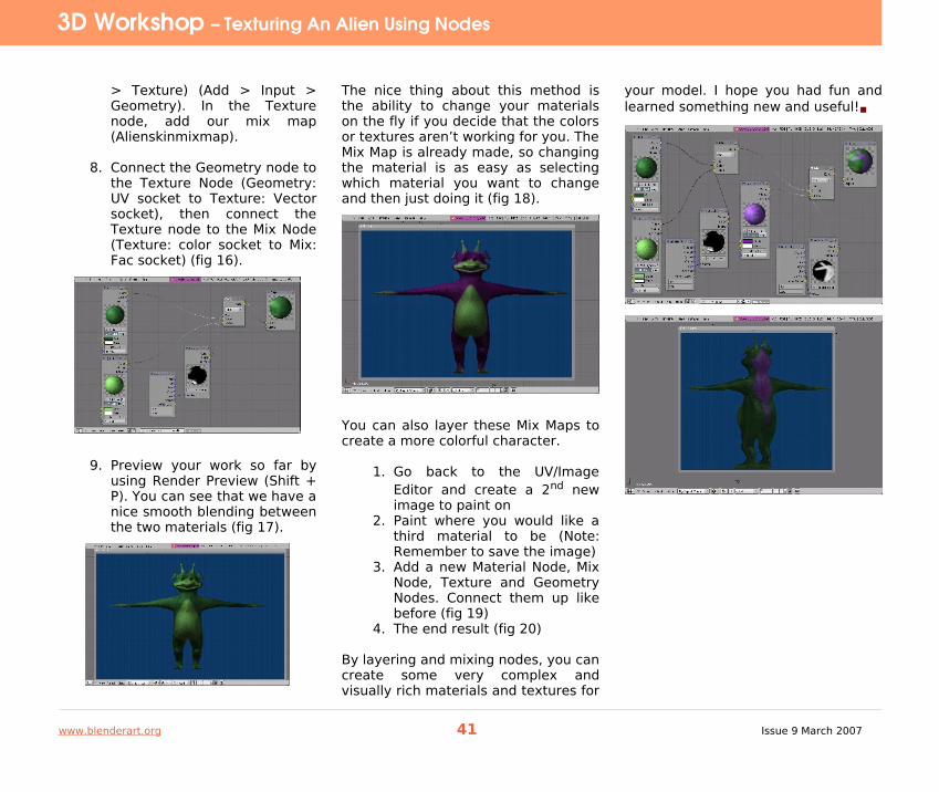
> Texture) (Add > Input > Geometry). In the Texture node, add our mix map (Alienskinmixmap).
8. Connect the Geometry node to the Texture Node (Geometry: UV socket to Texture: Vector socket), then connect the Texture node to the Mix Node (Texture: color socket to Mix: Fac socket) (fig 16).
9. Preview your work so far by using Render Preview (Shift + P). You can see that we have a nice smooth blending between the two materials (fig 17).
The nice thing about this method is the ability to change your materials on the fly if you decide that the colors or textures aren’t working for you. The Mix Map is already made, so changing the material is as easy as selecting which material you want to change and then just doing it (fig 18).
You can also layer these Mix Maps to create a more colorful character.
1. Go back to the UV/Image Editor and create a 2nd new image to paint on
2. Paint where you would like a third material to be (Note: Remember to save the image)
3. Add a new Material Node, Mix Node, Texture and Geometry Nodes. Connect them up like before (fig 19)
4. The end result (fig 20)
By layering and mixing nodes, you can create some very complex and visually rich materials and textures for
your model. I hope you had fun and learned something new and useful!■
www.blenderart.org 41 Issue 9 March 2007
3D Workshop – Texturing An Alien Using Nodes
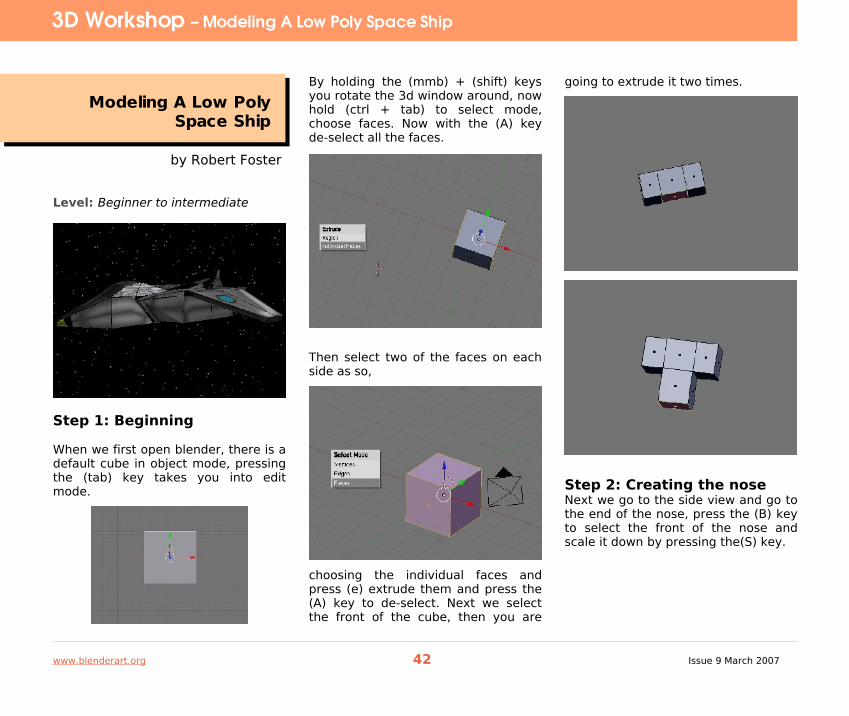
by Robert Foster
Level: Beginner to intermediate
Step 1: Beginning
When we first open blender, there is a default cube in object mode, pressing the (tab) key takes you into edit mode.
By holding the (mmb) + (shift) keys you rotate the 3d window around, now hold (ctrl + tab) to select mode, choose faces. Now with the (A) key de-select all the faces.
Then select two of the faces on each side as so,
choosing the individual faces and press (e) extrude them and press the (A) key to de-select. Next we select the front of the cube, then you are
going to extrude it two times.
Step 2: Creating the noseNext we go to the side view and go to the end of the nose, press the (B) key to select the front of the nose and scale it down by pressing the(S) key.
www.blenderart.org 42 Issue 9 March 2007
Modeling A Low PolySpace Ship
3D Workshop – Modeling A Low Poly Space Ship
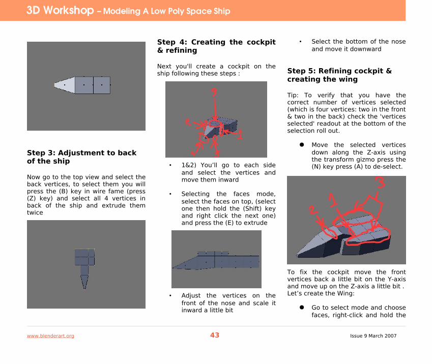
Step 3: Adjustment to back of the ship
Now go to the top view and select the back vertices, to select them you will press the (B) key in wire fame (press (Z) key) and select all 4 vertices in back of the ship and extrude them twice
Step 4: Creating the cockpit & refining
Next you'll create a cockpit on the ship following these steps :
• 1&2) You’ll go to each side and select the vertices and move them inward
• Selecting the faces mode, select the faces on top, (select one then hold the (Shift) key and right click the next one) and press the (E) to extrude
• Adjust the vertices on the front of the nose and scale it inward a little bit
• Select the bottom of the nose and move it downward
Step 5: Refining cockpit & creating the wing
Tip: To verify that you have the correct number of vertices selected (which is four vertices: two in the front & two in the back) check the 'vertices selected' readout at the bottom of the selection roll out.
● Move the selected vertices down along the Z-axis using the transform gizmo press the (N) key press (A) to de-select.
To fix the cockpit move the front vertices back a little bit on the Y-axis and move up on the Z-axis a little bit . Let’s create the Wing:
● Go to select mode and choose faces, right-click and hold the
www.blenderart.org 43 Issue 9 March 2007
3D Workshop – Modeling A Low Poly Space Ship
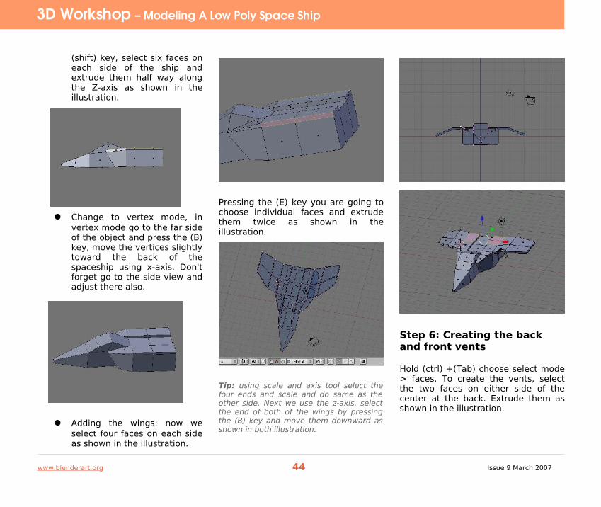
(shift) key, select six faces on each side of the ship and extrude them half way along the Z-axis as shown in the illustration.
● Change to vertex mode, in vertex mode go to the far side of the object and press the (B) key, move the vertices slightly toward the back of the spaceship using x-axis. Don't forget go to the side view and adjust there also.
● Adding the wings: now we select four faces on each side as shown in the illustration.
Pressing the (E) key you are going to choose individual faces and extrude them twice as shown in the illustration.
Tip: using scale and axis tool select the four ends and scale and do same as the other side. Next we use the z-axis, select the end of both of the wings by pressing the (B) key and move them downward as shown in both illustration.
Step 6: Creating the back and front vents
Hold (ctrl) +(Tab) choose select mode > faces. To create the vents, select the two faces on either side of the center at the back. Extrude them as shown in the illustration.
www.blenderart.org 44 Issue 9 March 2007
3D Workshop – Modeling A Low Poly Space Ship
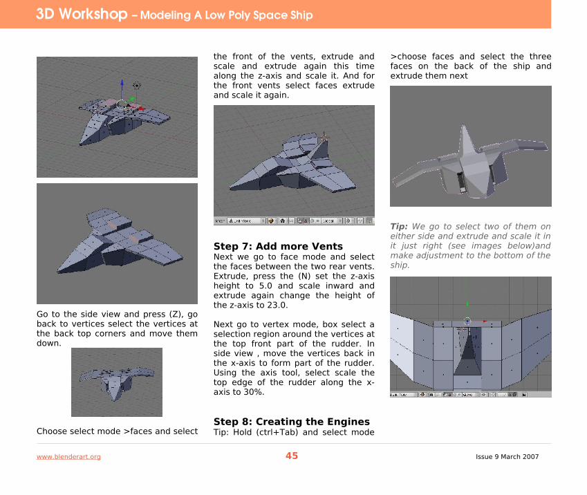
Go to the side view and press (Z), go back to vertices select the vertices at the back top corners and move them down.
Choose select mode >faces and select
the front of the vents, extrude and scale and extrude again this time along the z-axis and scale it. And for the front vents select faces extrude and scale it again.
Step 7: Add more VentsNext we go to face mode and select the faces between the two rear vents. Extrude, press the (N) set the z-axis height to 5.0 and scale inward and extrude again change the height of the z-axis to 23.0.
Next go to vertex mode, box select a selection region around the vertices at the top front part of the rudder. In side view , move the vertices back in the x-axis to form part of the rudder. Using the axis tool, select scale the top edge of the rudder along the x-axis to 30%.
Step 8: Creating the EnginesTip: Hold (ctrl+Tab) and select mode
>choose faces and select the three faces on the back of the ship and extrude them next
Tip: We go to select two of them on either side and extrude and scale it in it just right (see images below)and make adjustment to the bottom of the ship.
www.blenderart.org 45 Issue 9 March 2007
3D Workshop – Modeling A Low Poly Space Ship
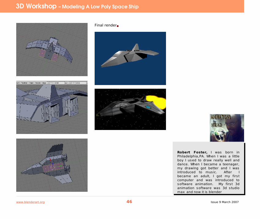
Final render■
www.blenderart.org 46 Issue 9 March 2007
3D Workshop – Modeling A Low Poly Space Ship
Robert Foster, I was born in Philadelphia,PA. When I was a little boy I used to draw really well and dance. When I became a teenager, my drawing got better and I was introduced to mus ic. After I became an adult, I got my firs t computer and was introduced to software animation. My firs t 3d animation software was 3d studio max and now it is blender
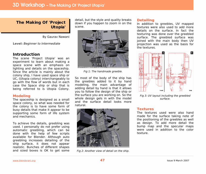
By Gaurav Nawani
Level: Beginner to Intermediate
IntroductionThe scene 'Project Utopia' was an experiment to learn about making a space scene with an emphasis on lighting and details on the spaceship. Since the article is mainly about the colony ship, I have used space ship or UC, (Utopia colony) interchangeably to go with the flow of words but in each case the Space ship or ship that is being referred to is Utopia Colony.
ModelingThe spaceship is designed as a small space colony, so what was needed for the colony is to have some form of busy details that make it appear to be supporting some form of life system and mechanics.
To achieve the details, greebling was used. I personally do not prefer using automatic greebling, which can be done with the help of few scripts available for Blender. Although auto greebling increases detailing of the ship surface, it does not appear realistic. Bunches of different shapes and sized boxes is OK to get some
detail, but the style and quality breaks down if you happen to zoom in on the scene.
Fig 1: The handmade greeble.
So most of the body of the ship has the greebles added to it by hand modeling, the main advantage of adding detail by hand is that it allows you to follow the design of the ship or the surface you are working on. So the whole design gels in with the model and the surface detail looks more natural.
Fig 2: Another view of detail on the ship.
DetailingIn addition to greebles, UV mapped textures were also used to add more details on the surface. In fact the texturing was done over the greebled surface. The greebled surface was joined with the main body then UV projection was used as the basis for the textures.
Fig 3: UV layout including the greebled surface.
TexturesThe textures used were also hand made for the surface taking note of the positioning of the greebles as well as design. To add more detail the bump map and the specular maps were used in addition to the color texture.
www.blenderart.org 47 Issue 9 March 2007
The Making Of 'Project Utopia'
3D Workshop – The Making Of 'Project Utopia'
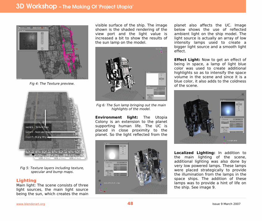
Fig 4: The Texture preview.
Fig 5: Texture layers including texture, specular and bump maps.
LightingMain light: The scene consists of three light sources, the main light source being the sun, which creates the main
visible surface of the ship. The image shown is the shaded rendering of the view port and the light value is increased a bit to show the results of the sun lamp on the model.
Fig 6: The Sun lamp bringing out the main highlights of the model.
Environment light: The Utopia Colony is an extension to the planet supporting human life. The UC is placed in close proximity to the planet. So the light reflected from the
planet also affects the UC. Image below shows the use of reflected ambient light on the ship model. The light source is actually an array of low intensity lamps used to create a bigger light source and a smooth light effect.
Effect Light: Now to get an effect of being in space, a lamp of light blue color was used to create additional highlights so as to intensify the space volume in the scene and since it is a blue color, it also adds to the coldness of the scene.
Localized Lighting: In addition to the main lighting of the scene, additional lighting was also done by very low powered lamps. These lamps were placed strategically to provide the illumination from the lamps in the space ships. The addition of these lamps was to provide a hint of life on the ship. See image 9.
www.blenderart.org 48 Issue 9 March 2007
3D Workshop – The Making Of 'Project Utopia'
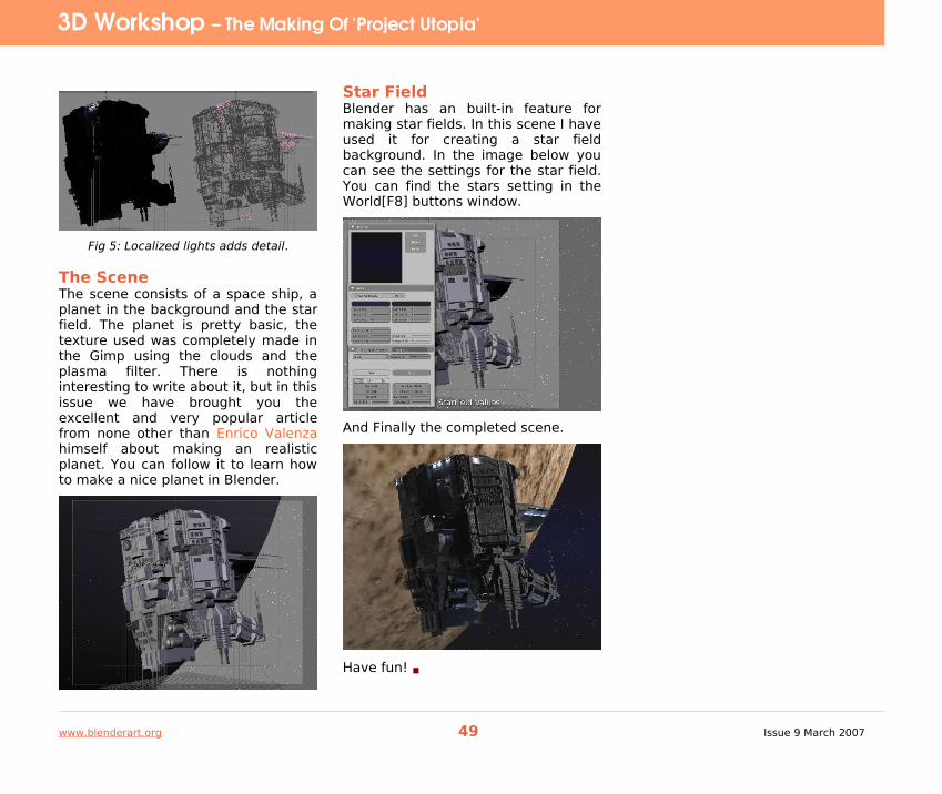
Fig 5: Localized lights adds detail.
The SceneThe scene consists of a space ship, a planet in the background and the star field. The planet is pretty basic, the texture used was completely made in the Gimp using the clouds and the plasma filter. There is nothing interesting to write about it, but in this issue we have brought you the excellent and very popular article from none other than Enrico Valenza himself about making an realistic planet. You can follow it to learn how to make a nice planet in Blender.
Star FieldBlender has an built-in feature for making star fields. In this scene I have used it for creating a star field background. In the image below you can see the settings for the star field. You can find the stars setting in the World[F8] buttons window.
And Finally the completed scene.
Have fun! ■
www.blenderart.org 49 Issue 9 March 2007
3D Workshop – The Making Of 'Project Utopia'
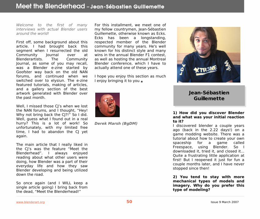
Welcome to the first of many interviews with actual Blender users around the world!
First off, some background about this article. I had brought back this segment when I resurrected the old Community Journal over at Blenderartists. The Community Journal, as some of you may recall, was a Blender e-zine started by Goofster way back on the old NAN forums, and continued when we switched over to elysiun. The e-zine featured tutorials, making of articles, and a gallery section of the best artwork generated with Blender over the past month.
Well, I missed those CJ’s when we lost the NAN forums, and I thought, “Hey! Why not bring back the CJ?!” So I did. Well, guess what I found out in a real hurry? This is a lot of work! So unfortunately, with my limited free time, I had to abandon the CJ yet again.
The main article that I really liked in the CJ’s was the feature “Meet the Blenderhead”. I always enjoyed reading about what other users were doing, how Blender was a part of their everyday life and how they saw Blender developing and being utilized down the road.
So once again (and I WILL keep a single article going) I bring back from the dead, “Meet the Blenderhead!”
For this installment, we meet one of my fellow countrymen, Jean-Sébastien Guillemette, otherwise known as Ecks. Ecks has been a longstanding, respected member of the Blender community for many years. He's well known for his distinct style and many wins in the annual Blender F1 contest, as well as hosting the annual Montreal Blender conference, which I have to actually attend one of these years.
I hope you enjoy this section as much I enjoy bringing it to you ■
Derek Marsh (BgDM)
1) How did you discover Blender and what was your initial reaction to it? I discovered blender a couple years ago (back in the 2.22 days!) on a game modding website. There was a tutorial about how to create your own spaceship for a game called Freespace, using Blender. So I downloaded it, tried it, and closed it... Quite a frustrating little application at first! But I reopened it just for fun a couple months later, and I have never stopped since then!
2) You tend to stay with more mechanical types of models and imagery. Why do you prefer this type of modeling?
www.blenderart.org 50 Issue 9 March 2007
Jean-Sébastien Guillemette
Meet the Blenderhead – Jean-Sébastien Guillemette
I think it’s simply because I always had an interest in machinery and vehicle design. Also, as I mentioned above, my first days with blender were about creating spaceships for a game and it probably influenced me a lot to keep doing such things.
3) How do you see yourself progressing in learning and developing your skills in Blender? I definitely have to start learning organic modeling! But, on a more serious note, I think one of the best ways to get better is by participating in challenges. The few I have done in the past really helped me out. So maybe I’ll take another go at the 2007 F1 challenge that is running right now. I’ll definitely participate (and finish my entry) in the next CG Society challenge.
4) You started an original movie project, composed of artists from around the world. What did you learn from that experience and would you do it again? I learned that it is almost impossible to accomplish. I was a bit naive, like everyone starting a new hobby such as 3d animation, to think I could accomplish a full length movie with people living in different countries, with different mentalities and in different time zones that I never met! It sure was a great experience. We all learned a lot about modeling, texturing, and animating. We also learned a lot about how a project
should not be organized! Although that project failed completely, I would still be up to making such a project... just a lot smaller, and with fewer people that I can actually meet. So who knows, maybe someday I’ll start a new project!
5) As host/organizer of the Montreal Blender Conference, which coincides with the yearly Blender Conference, how has that progressed over the past few years and what has been your personal highlight from those meetings? If we compare the past two conferences with the first one (was it 5 years ago?) we can definitely say that the Blender user base has grown a lot in the past years! We had around 30 people on both days in the two last years, with enough presentations and activities to fill every minute of the day. Although I’d like the conference to grow to another level in which we could have sponsors, prizes, etc., I must say that from year to year, it’s more and more complicated for me to handle the conference because of my other responsibilities (i.e. school/job). I’ve had a lot of help already in the past years from people like Jonathan Williamson (mr_bomb) and François Joanette (Le_Mackeux) for the computer labs, and the guys from Linart for the t-shirts. Next year, if others think they can help me, be sure to drop me an email! As for my highlight of those meetings, I’d
personally say that mr_bomb is the star of the conferences. With his organic modeling tutorial and his almost limitless knowledge of Blenders modeling tools and techniques, he impressed all of us more than once. I’d suggest you check out his DVD if you are interested in organic modeling!
6) You have enjoyed some commercial success with some of your Blender work. Can you describe the process in obtaining that work and was it worth it?
Actually, I was quite lucky. It’s not really a trick or anything. The only thing I did was post my stuff on several websites to get comments and it came to the eye of a few employers who needed some sci-fi stuff done. My work was at the right spot at the right moment, and that’s why they contacted me. It was definitely worth it to work with most of them, but some were probably the most annoying people I've ever had contact with. Well, I guess its part of the job!
7) You have spoken many times about opening a CG studio of your own for commercial work. Can you describe what your target market is and how you plan on getting there? I’m currently studying Cinema in college, and when I’m done I’m going into a 3D animation school
www.blenderart.org 51 Issue 9 March 2007
Meet the Blenderhead – Jean-Sébastien Guillemette
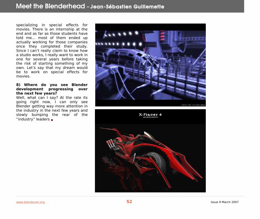
specializing in special effects for movies. There is an internship at the end and as far as those students have told me... most of them ended up actually working for those companies once they completed their study. Since I can’t really claim to know how a studio works, I really want to work in one for several years before taking the risk of starting something of my own. Let’s say that my dream would be to work on special effects for movies. 8) Where do you see Blender development progressing over the next few years? Well, what can I say? At the rate its going right now, I can only see Blender getting way more attention in the industry in the next few years and slowly bumping the rear of the “industry” leaders ■
www.blenderart.org 52 Issue 9 March 2007
Meet the Blenderhead – Jean-Sébastien Guillemette
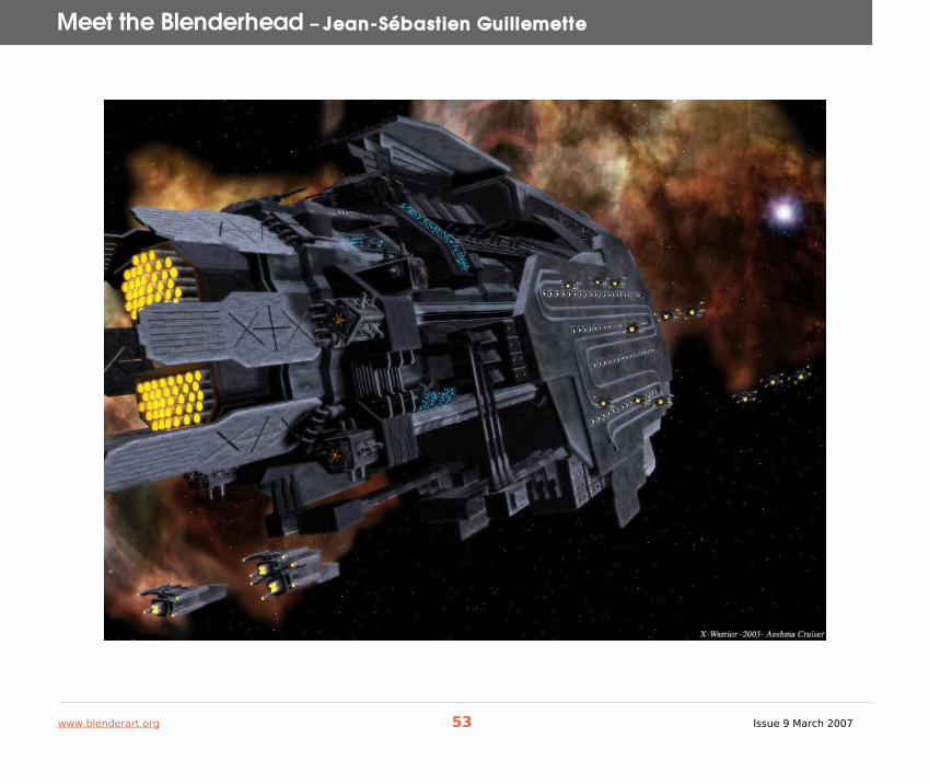
www.blenderart.org 53 Issue 9 March 2007
Meet the Blenderhead – Jean-Sébastien Guillemette

www.blenderart.org 54 Issue 9 March 2007
Meet the Blenderhead – Jean-Sébastien Guillemette
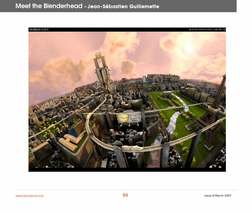
www.blenderart.org 55 Issue 9 March 2007
Meet the Blenderhead – Jean-Sébastien Guillemette
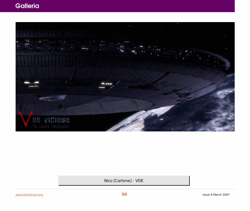
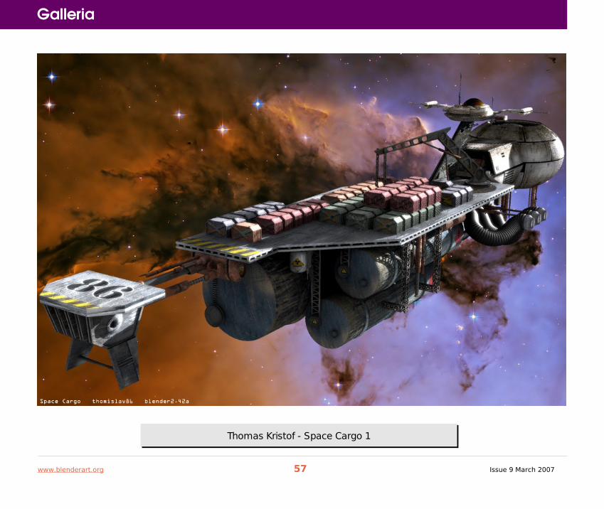
www.blenderart.org 57 Issue 9 March 2007
Thomas Kristof - Space Cargo 1
Galleria
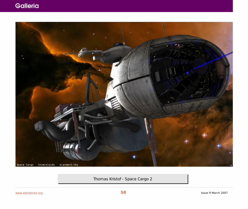
www.blenderart.org 58 Issue 9 March 2007
Thomas Kristof - Space Cargo 2
Galleria
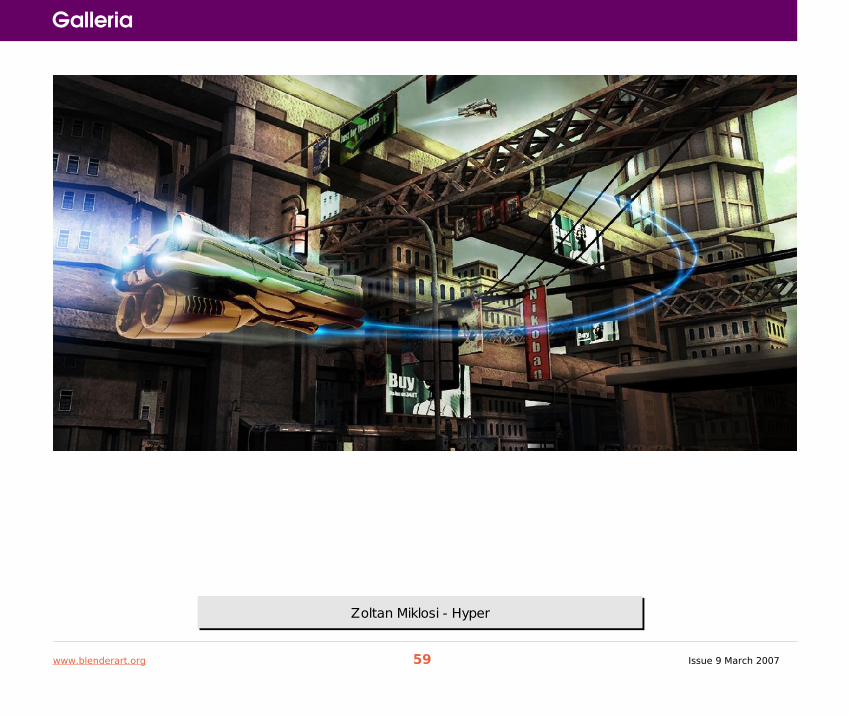
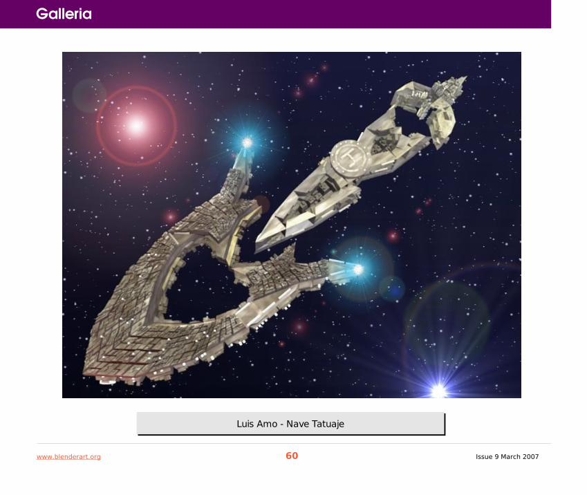
www.blenderart.org 60 Issue 9 March 2007
Luis Amo - Nave Tatuaje
Galleria
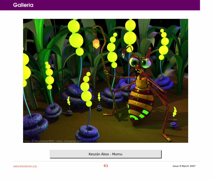
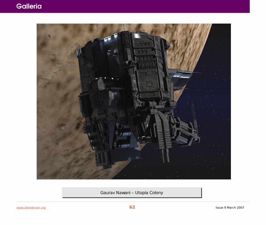
www.blenderart.org 62 Issue 9 March 2007
Galleria
Gaurav Nawani – Utopia Colony
www.blenderart.org 63 Issue 9 March 2007
Upcoming...
blenderart.org does not takes any responsibility both expressed or implied for the material and its nature or accuracy of the information which is published in this PDF magazine. All the materials presented in this PDF magazine have been produced with the expressed permission of their respective authors/owners. blenderart.org and the contributors disclaim all warranties, expressed or implied, including, but not limited to implied warranties of merchantability or fitness for a particular purpose. All images and materials present in this document are printed/re -printed with expressed permission from the authors/owners.
This PDF magazine is archived and available from the blenderart.org website. Th e blenderart magazine is made available under Creative Commons 'Attribution-NoDerivs2.5' license.
The CC license is available at http://creativecommons.org/licenses/by-nd/2.5/legalcode
Disclaimer
Organic Modeling
Focusing on bugs/plants,reptiles/amphibians (frogs etc.)Oh and those creepy humans.
Issue 10 May 2007
Related Documents