BLEED SYSTEM .S INLET ERONAUTICS AND SPACE ADMINISTRATION WASHINGTON, D. C. JANUARY 1973 https://ntrs.nasa.gov/search.jsp?R=19730007094 2020-03-15T10:28:46+00:00Z

Welcome message from author
This document is posted to help you gain knowledge. Please leave a comment to let me know what you think about it! Share it to your friends and learn new things together.
Transcript
BLEED SYSTEM .S INLET
ERONAUTICS A N D SPACE ADMINISTRATION WASHINGTON, D. C. JANUARY 1973
https://ntrs.nasa.gov/search.jsp?R=19730007094 2020-03-15T10:28:46+00:00Z
1. Report No. 2. Government Accession No.
NASACR 2187 4. Title and Subtitle
DESIGN OF A BLEED SYSTEM FOR A MACH 3.5 INLET
7. Author(s)
J. Syberg and T. E. Hickcox
9. Performing Organization Name and Address
The Boeing Company P.O. Box 3707 Seattle, Washington 98 124
3. Recipient's Catalog No.
5. Report Date
6. Performing Organization Code
January 1973
8. Performing Organization Report NO.
D6-60168 10. Work Unit No.
11. Contract or Grant No. I NAS2-6643
Boundary layer Analytic design procedure Bleed systems Supersonic Axisymmetric
14. Sponsoring Agency Code F
UNCLASSIFIED-UNLIMITED
13. Type of Report and Period Covered
12. Sponsoring Agency Name and Address Contractor ReDort National Aeronautics and Space Administration Washington, D.C., 20546
19. Security Classif. (of this report) 20. Security Classif. (of this page)
Unclassified Unclassified
I 15. Supplementary Notes
16. Abstract
An analytical bleed system design procedure is applied t o a Mach 3.5, axisymmetric, translating centerbody inlet. The design features a traveling centerbody bleed system with a ducting arrangement separating low-, medium-, and high-pressure bleed. Three forward plenums and nine throat plenums are installed on the centerbody to meet the bleed requirements in the started Mach range between 1.6 and 3.5. The cowl contains four stationary plenums, three for forward and one for throat bleed. To achieve maximum bleed plenum pressure and thereby minimize bleed drag all bleed holes are inclined 20" to the surface except in the cowl throat region. Here the requirement of high stability margin with minimum total pressure recovery penalty resulted in 90' bleed holes. The bleed hole diameter varies from bleed plenum t o bleed plenum to achieve the most efficient boundary layer control, while the bleed exits are sized to operate at the highest possible plenum pressure without unchoking the bleed holes. Bleed flow rates, bleed plenum pressures, and boundary layer development along the cowl and centerbody are predicted over the entire started Mach range.
21. NO. of Pages 22. Price'
8 8 $3.00
18. Distribution Statement I 17. Key Words (Suggested by Author(sl ) I Inlets Bleed holes
* For sale by the National Technical Information Service, Springfield, Virginia 22151
DESIGN OF A BLEED SYSTEM
FOR A MACH 3.5 INLET
By J . Syberg and T. E. Hickcox The Boeing Company
SUMMARY
A bleed system has been designed for a Mach 3.5 inlet using analytical procedures which promise t o save many wind tunnel testing hours. The design is based on a model size compat- ible with the existing NASA Ames 1/3scale inlet model and on freestream conditions cor- responding to those in the NASA Ames 8- by 7-ft supersonic wind tunnel.
This report first describes the analytical procedures and tools used in the bleed system design. The operating characteristics of the inlet are then presented in the form of surface pressures and boundary layer development without boundary layer control. The proposed bleed systems for centerbody and cowl are then described, along with the design considera- tions for Mach 3.5 and off-design conditions. Next, the boundary layer growth is predicted throughout the started Mach number range with the bleed system operating. Finally, possible problem areas are identified and the overall system is evaluated.
Application of the analytical design procedure indicated the need for a bleed system with unusual and complex features that would be unlikely to evolve from normal wind tunnel development testing. The centerbody has a “traveling” bleed system with a ducting arrange- ment separating low-, medium-, and high-pressure bleed regions. Three forward bleed plenums and nine throat plenums are included, with the novel feature that one forward plenum is located among the throat plenums to provide sufficient forward bleed at off-design Mach numbers. The cowl contains four stationary plenums, three for forward bleed and one for throat bleed. The exit areas for the various bleed plenums are sized to operate at the highest possible plenum pressures without unchoking the bleed holes. All centerbody bleed holes and the forward cowl bleed holes are inclined 20” t o the surface, primarily to achieve maximum bleed plenum pressure and thereby minimize bleed drag. The cowl throat bleed holes are normal t o the surface to maximize the normal shock stability margin. The bleed hole diameter varies from bleed plenum to bleed plenum to achieve the most efficient boundary layer control.
With the proposed system the bleed flow rate is 13.3% of the lip flow (0.133 WL) at Mach 3.5, with 0.089 WL forward bleed and 0.044 WL throat bleed. Analysis indicates that this amount of forward bleed is near the minimum bleed rate required to achieve attached flow in the supersonic diffuser and provide a full boundary layer velocity profile in the throat ahead of the normal shock. Isentropic compressions and oblique shock wave reflections at off-design Mach numbers are in general well controlled. Boundary layer separation at oblique shock reflections is predicted at some off-design Mach numbers, but rapid reattachment is expected in all of these cases due t o favorable downstream pressure gradients coupled with high bleed rates near these critical regions.
INTRODUCTION
The development of bleed systems for boundary layer control in supersonic inlets has in the past depended mainly on extensive wind tunnel tests. The tests were complex, time con- suming, and did not always allow optimization of the system. An analytical procedure (ref. 1 ) has now been developed for the design of bleed systems based on theoretical analysis and extensive experimental data. Using the procedure allows analytic definition of a bleed system, which may then be optimized in the wind tunnel with less testing.
The present work applies this procedure t o the design of a bleed system for a Mach 3.5 inlet with the objective of providing satisfactory operation across a wide range of “started” Mach numbers with adequate tolerance to transient disturbances in upstream Mach number and angle of incidence, and downstream corrected weight flow. The work included the design of internal cowl and centerbody contours, design of the bleed pattern, bleed hole geometry, bleed plenum arrangement, bleed flow ducting and exits, and the prediction of bleed system performance. The inlet and bleed system geometry is sized for an existing 1/3-scale supersonic inlet model (ref. 2) operating within the flow conditions available in the NASA Ames 8- by 7-ft supersonic wind tunnel. The present work was carried out under contract NAS 2-6643 (ref. 1).
Portions of the procedure and technology have been applied before (refs. 2 and 3), but never as an entire package. The present application of the procedure is the first time a com- pletely analytical design of the bleed system has been done prior to model testing. As such, a thorough validation of the procedure is needed from wind tunnel tests of the 1/3-scale inlet.
2

SYMBOLS
area
bleed hole area
cowl lip projected area
sonic area ratio
bleed hole diameter
wall temperature recovery-wall temperature/freestream total temperature
boundary layer shape factor-6*/8
aspect ratio of bleed hole-length/diameter
Mach number
local Mach number
boundary layer power law velocity profile exponent
pressure
bleed hole mass flow coefficient-actual flow/ideal choked flow at same conditions
inlet radius
cowl lip radius
circumferential bleed hole spacing, Y/D
temperature
axial velocity component
theoretical freestream airflow through an area equal t o the cowl lip area
nondimensionalized bleed flow rate
nondimensionalized axial coordinate
AX/RL nondimensional forward translation of centerbody from Mach 3.5 position
3

Y half of the circumferential center-to-center spacing between holes in one row of bleed holes
Y boundary layer coordinate normal to wall
CY bleed hole angle relative to surface
6 boundary layer thickness
6" boundary layer displacement thickness
P density
e boundary layer momentum thickness
Subscripts
i incompressible
PL plenum
R
S static
s,c
t h throat
TO, T, freestream total
W wall
property derived from analysis of Reyhner
property derived from analysis of Sasman and Cresci
00 freestream
1 upstream side of oblique shock reflection or normal shock
4
2
3
downstream side of normal shock
downstream side of oblique shock reflection
APPROACH
Procedure
The first step in the bleed system design procedure for a new inlet contour is t o deter- mine a centerbody translation schedule versus freestream Mach number that will provide effi- cient internal compression as well as adequate tolerance against transient changes in Mach number and angle of incidence. These conflicting requirements can be met by maintaining the throat Mach number near 1.25 in the mixed-compression operating range.
Once the translation schedule has been established, the inviscid flowfield solutions are computed to determine the inlet operation for that schedule. These solutions are computed with a method of characteristics program at small Mach number increments (say, A&= 0.1) over the started Mach number range. The surface static pressure distributions are plotted along with the characteristic network and shock pattern. A map of surface static pressure versus centerbody translation, or freestream Mach number, is made to facilitate selection of bleed bands in regions of high static pressure. (High surface static pressures allow high bleed plenum pressures and therefore low bleed drag.) The surface Mach number distributions from the inviscid flow solutions are used as input for the boundary layer calculations.
The boundary layer development along both the cowl and centerbody is then computed using a boundary layer computer program (ref. 4). The first solutions are computed without bleed at each Mach number for which an inviscid solution has been calculated. The program calculates boundary layer profile distortion parameters along the surfaces, which are mapped versus centerbody translation and freestream Mach number for both the centerbody and cowl. These maps are then used to identify regions of high profile distortion (i.e., regions where boundary layer separation is likely) and thus to determine bleed locations for optimum boundary layer control.
An additional consideration when locating bleed regions is that, due to the finite cowl lip bluntness and displacement effects of the boundary layer, shock reflections and pressure gradients move forward in the actual inlet as compared to the inviscid solution. Thus, if the boundary layer analysis indicates that bleed is required in a given pressure gradient or just ahead of a shock the bleed is moved slightly forward of the location that would be selected without considering these real flowfield effects.
Next, several alternate bleed configurations are studied at the design Mach number. For each of these configurations the boundary layer solutions are obtained with bleed included. Throat bleed is not included, since for the critical normal shock position essentially all bound- ary layer control upstream of the normal shock must come from forward bleed. On the basis of results obtained from these solutions, the design Mach number bleed system is modified to produce the lowest throat boundary layer distortion and displacement thickness at the lowest possible bleed rates subject t o the aforementioned constraints on bleed location. Knowing the bleed locations and flow rates, the bleed areas can be calculated for the selected hole angles.
5
Throat bleed rates are selected on the basis of past experience. Basically, the throat bleed rate required for normal shock/boundary layer interaction control and good subsonic diffuser performance has been found to be a function of throat blockage. Thus, the throat bleed rate is chosen on the basis of throat blockage with the selected forward bleed.
Based on off-design requirements, an overall bleed system compatible with the design Mach number system selected above is planned. Using the surface pressure and boundary layer distortion maps, probable off-design problem areas are determined. Selected off-design cases are then run with various bleed configurations to cover the suspected problem areas. Results from these runs are used to modify and improve the system for off-design operation, with possible modifications to the design Mach number bleed system.
This last step completes the definition of the entire bleed system. At this point, on the basis of previously determined bleed geometry and local Mach number, the bleed rates and maximum plenum pressures are determined for any remaining range of operation. The bound- ary layer characteristics are then computed with these bleed rates at small Mach number increments. If these solutions identify any new problem areas not anticipated in the previously computed cases, modification of the bleed system is undertaken.
The viscous flow analysis does not account for bleed within a shock interaction. For this reason, numerical problems may be encountered when bleed occurs in or just ahead of a shock reflection. Since problems may result, and since it is known that cumulative viscous effects tend to move the shock forward in the real flowfield, if a shock reflection falls within a bleed region in an off-design case that region is generally moved downstream of the reflection for the analysis. If the bleed band is fairly wide it is split into two parts-one ahead of the shock and one aft.
As a check on the validity of the final bleed system design, the Combined Flowfield Analysis (ref. 5 ) , an inviscid-viscous flowfield solution, is used to evaluate the viscous and bleed effects on the flowfield, in particular whether the bleed is properly positioned to control the pressure gradients and shock reflections. For this bleed system two checkout cases were run, the design Mach number case and a selected off-design case.
As a check on possible inlet restart problems, several inviscid restart cases are run to determine the flowfield with large centerbody extensions. These cases are examined to deter- mine whether boundary layer separation problems exist which could cause the started inlet to unstart as the centerbody is retracted to design position.
Design Tools
As discussed above, the analytical procedure uses several design tools. These include two computer programs t o calculate inviscid and viscous inlet flowfields.
The inviscid flow solutions are calculated using Boeing program TEM 137, the MOCHA (Method _Of C-racteristics) program, which will compute two-dimensional or axisymmetric, internal or external, rotational flowfields with multiple shocks. The complete solution of
6
intersection of like and opposite family shocks is included, as well as shock reflections; shocks or expansions from boundary corners; pressure boundaries with separation, reattachment, and intersections with shocks; the coalescence of Mach lines to form an embedded shock; and the capability to remove mass flow at a scoop.
The boundary layer (viscous) solutions are calculated using Boeing computer program TEM 139 (ref. 4). This program provides a finite-difference solution of the boundary layer equations. I t computes laminar and turbulent boundary layer development on two- dimensional or axisymmetric surfaces with or without heat transfer. It will also compute regions of bleed or blowing. Oblique shock/boundary layer interactions are computed using a control volume analysis. Boundary layer transition may be specified as occurring at a given location or given momentum thickness Reynolds number.
The inviscid and viscous programs have been combined in a procedure called the Com- bined Flowfield Analysis t o provide a prediction of the flowfield with viscous effects. This procedure accounts for cowl bluntness, boundary layer displacement thickness effects on the inviscid core flow, shock interactions, and bleed effects. As described in reference 5, this analysis provides a much improved prediction of the real flowfield as compared to a strictly inviscid solution.
An additional consideration, discussed in reference 5 , is the fact that real bleed holes are less efficient at improving the boundary layer than theoretical ideal bleed. That is, bleed holes have some roughness which tends to counteract the effect of mass removal. To correct for this effect in the analysis a bleed efficiency, 9, is assigned such that for the analysis of TEM 139 the bleed removed is the actual bleed multiplied by the efficiency.
An important requirement for the design of an effective and efficient bleed system is accurate data for the flow coefficients of bleed holes. A combination of Boeing and NACA data has been used to define these flow characteristics, as shown in figure 1. The data available are valid for limited ranges of bleed hole size, spacing, and length. In addition, the character- istics were obtained with a full boundary layer velocity profile upstream of the bleed holes. These limitations may result in inaccuracies in the bleed system design. To minimize the inaccuracies, the geometric variables will be chosen as close as possible to the available data.
Boundary Layer Distortion Parameters
The bleed system design procedure is based on maintaining limits on the boundary layer profile distortion in the supersonic diffuser to prevent large separations and to provide suffi- cient upstream control to keep the throat boundary layer profile close to a full profile. The parameters used t o evaluate boundary layer distortion are discussed below.
In previous applications of the bleed system design procedure, a different boundary layer analysis was used. The program used, TEM 123, employed the method of Sasman and Cresci, which is an integral solution. The compressible flow problem is transformed to the incom- pressible plane where the integral solution is computed, then retransformed to the compress- ible plane. The integral solution in the incompressible plane uses a power law velocity profile,
7
and thus the incompressible power law exponent, Ni, (called Ni-s,c here) was used as a meas- ure of profile distortion. Since the present application of the design procedure uses a more accurate finite-difference compressible flow solution, TEM 139, the parameter Ni-s,c is not readily available. Instead, a velocity distortion parameter based on the actual velocity profile as computed i n TEM 139 is used. The following are standard definitions:
Displuceinent Thickrzess
Monien turn Thic kriess
(incompressible)
(incompressible)
Shape Factor
H~ = tii*/ei (incompressible)
The parameter Hi is defined simply by using the existing velocity profile and neglecting the density variation that is normally included in the shape factor. This parameter is then not a function of edge Mach number or wall temperature recovery, as is Ni-s,c, which may vary for a fixed velocity profile. Because Hi is based solely on the shape of the actual velocity profile and is independent of local Mach number and wall temperature recovery, it is felt that it is a better representation of actual boundary layer distortion than the previously used Ni-s,c. The shape factor Hi is therefore used as the primary distortion parameter in the bleed system design.
The computer program TEM 139 is a finite-difference method which requires no assump- tion as to the shape of the velocity profile. If, however, it is assumed that the velocity profiles computed with the finite-difference procedure can be well represented by a power law
then the shape factor Hi can be used to define a boundary Ni-R-
layer velocity profile exponent,
8
t ~. ~

or
N ~ - R = 2/( Hi - 1 )
This parameter is called Ni in this report and is used as the contract-specified boundary layer distortion parameter. The relationship between the three parameters, Ni-s c, Ni,and Hi, is shown in figure 2. An Hi value above 1.8 corresponds to a highly distorted velocity profile, and the boundary layer program will usually indicate separation if Hi exceeds a value of about 2.0. A “full” profile, normally defined as Ni = 7, corresponds to Hi = 1.28.
As previously mentioned, the design procedure is based on maintaining limits on the dis- tortion parameter in the supersonic diffuser and keeping the throat boundary layer profile close to a full profile. An upper limit of about 1.7 is used for Hi in the supersonic diffuser, except in the regions just downstream of oblique shock reflections. Higher Hi values can be tolerated in these regions because the profile deterioration from the shock pressure rise is usually followed by a rapid natural redevelopment to lower Hi values. The upstream boundary layer control is adjusted to also provide a reasonably full profile in the throat region. Experi- ence has shown that this ensures a controllable normal shock/boundary layer interaction when the normal shock is within the operating range of the design point. The throat bleed is there- fore only used for normal shock/boundary layer control and not for profile improvement upstream of the shock.
RESULTS
Inlet Description and Operating Characteristics Without Bleed
The Mach 3.5 inlet contours, for which a bleed system has been designed, are described in reference 6 . The inlet has a 1 OOstraight cone centerbody with a lo positive cowl lip angle. The inlet contours and area progression with centerbody translation are shown in figure 3. The point-by-point contour definition and curve-fit type are provided in table 1.
9

Table I.-Inlet Contour Definition
XJRL R I R L dRJdX Curve f i t type 1 0.0
4.0 4.1 4.2 4.3 4.4 4.5 4.55 4.6 4.65 4.7 4.8 4.9 5.1 5.3 5.5 5.6 5.7 5.8 5.9 6.0 6.1 6.2 6.28
0.107
0.0729
0.065
~
2.86
3.1 3.2 3.4 3.6 3.8 4.0 4.1 4.2 4.25 4.3 4.4 4.5 4.55 4.6 4.65 4.7 4.8 4.9 5.0 5.1
5.6 5.8 5.9 6.0 6.1 6.2 6.3 6.4 6.5 6.6 6.7 6.8 6.9
Smoothed cubic spline If
4, Smoothed cubic spline
I f
il Smoothed cubic spline
1 ,
0.0
0.70532 0.7228 0.7387 0.751 2 0.7 59 0.7625 0.763 0.7625 0.761 1 0.7585 0.7504 0.7391 0.7 120 0.6829 0.6525 0.6362 0.618 0.5973 0.5744 0.5467 0.5093 0.4564 0.4
1 .o
1.0041 88 1.0054 1.0051 0.99996 0.9882 0.9681 0.954 0.9364 0.9261 0.91 54 0.8949 0.8768 0.8695 0.864 0.86 0.8572 0.8533 0.851 I 0.8502 0.85
0.85 0.8574 0.8646 0.8735 0.8839 0.8946 0.9050 0.9145 0.9227 0.9299 0.9368 0.9435 0.95
~
Center body
0.1 7633
0.1 7633
0.144
0.052
0.0
1 t Straight line
t Smoothed cubic spline
Smoothed cubic spline
Smoothed cubic spline
Smoothed cubic spline 1 t
-0.0646
-0.1295 Smoothed cubic spline
Smoothed cubic spline
-0.1 53
Smoothed cubic spline
10
The translation schedule for the inlet was developed along with the contour, and is given in reference 6. Using this schedule, the MOCHA inviscid computer program was run for each AMw = 0.1 between Mach 3.5 and Mach 1.6. The results, in the form of surface static pres- sures, characteristic networks, and shock patterns, are presented in the appendix. It was found that there were two portions of the Mach number range in which a relatively strong oblique shock system produced subsonic flow (locally) ahead of the throat. These are between Mach 2.8-3.3 and Mach 1.7-2.0. A map of static pressure along the surface as a function of center- body translation, or Mach number, is shown for the centerbody and cowl, respectively, in figures 4 and 5 .
For each A&= 0.1 between Mach 3.5 and Mach 1.6 the boundary layer was calculated without bleed using TEM 139. These predictions were made for the system sized for the 1/3- scale model (RL = 9.788 in.) for testing in the NASA Ames 8- by 7-ft supersonic wind tunnel. Resulting maps of Hi and Ni along the centerbody and cowl surfaces are presented in figures 6 through 9. These indicate that, without bleed, separation occurs on the centerbody in the adverse pressure gradient between the first and second shock reflection between Mach 3.5 and Mach 3.2. Between Mach 3.2 and Mach 2.5, separation occurs at the second centerbody shock reflection. Between Mach 2.5 and Mach 2.2, separation occurs between the second and third centerbody shock reflections. Between Mach 2.2 and Mach 1.7, separation occurs at the third centerbody shock reflection, and at Mach 1.6 separation is predicted at the first centerbody shock reflection.
On the cowl, without bleed, separation is indicated at the first cowl shock reflection between Mach 3.5 and Mach 2.9. Between Mach 2.9 and Mach 2.7, separation occurs at the second cowl shock reflection. Between Mach 2.7 and Mach 1.7, the solution does not separate upstream of the throat. At Mach 1.6 separation is predicted at the first cowl shock reflection.
Six summary maps of surface properties are, at this point, available for use in design of the bleed system. Figures 4 and 5 provide surface static pressure on centerbody and cowl respectively, while figures 6, 7, 8, and 9 provide boundary layer Hi along centerbody and cowl, and boundary layer Ni along centerbody and cowl, respectively. The static pressure maps are used primarily to position bleed bands, taking advantage of the highest possible sur- face pressure in a given region where bleed is required. The maps are also used in the initial planning of the overall system as they define regions of strong adverse pressure gradient and lugh-pressure-ratio shock reflections. The boundary layer distortion maps, primarily the Hi maps, are used t o determine bleed location. Bleed must obviously be placed ahead of all separations t o provide profile improvement. In regions of adverse boundary layer development leading to separation, bleed must be placed ahead of any steep rise in Hi and must be used to produce levels of Hi acceptably below separation in the regions of adverse development behind the bleed. For cases of separation at shock reflections, bleed must be provided upstream of the shock reflection and must be distributed t o provide an improved profile going into the interaction.
Those separations that occur at a shock reflection may be caused by either a distorted boundary layer profile (high Hi) or high shock strength, or a combination of these. Bleed is used to control the boundary layer profile distortion, while shock strength can only be con- trolled by inlet contourmodifications.
11
When separation is predicted at a shock reflection, no prediction is made as to the size of that separation. The separation could be a small one completely contained within the shock interaction, or i t could be a massive separation. Therefore, shocks that are strong enough to always produce a separation within the interaction regardless of upstream boundary layer shape stop computation by TEM 139.
A shock may be strong enough to always produce some separation, even with a full boundary layer profile upstream. A criterion for defining the shock strength which produces separation with a full upstream profile has been developed in reference 7. Roughly, this criterion is that when the numerical value of shock reflection static pressure ratio becomes larger than the numerical value of the upstream Mach number, separation is likely. Figures 10 and 11 present the upstream Mach number and static pressure ratio versus freestream Mach number on the centerbody and cowl, respectively, for the shock reflections at which separa- tion occurs at some Mach numbers. From this plot and the reference 7 separation criterion, it becomes obvious why some of the separations for the no-bleed cases occur. The shock reflec- tions are so strong at some Mach numbers that the boundary layer will separate with a full upstream profile. Consequently, there may be regions in which it is not possible to get an attached solution at a shock reflection, even with the addition of upstream bleed. At Mach 1.6 both the cowl and centerbody show separation at the first shock reflection. Since these separa- tions are so far forward and occur at this low Mach number where “started” operation may not be required, the design of the bleed system will not account for them.
The relatively strong shocks encountered are a result of the inlet contours. They are caused when one of the cowl shock reflections passes near the maximum second derivative of the contour on the cowl. Figure 12 shows the cowl shock positions with the maximum second derivative location. The rises in pressure in figures 10 and 1 1 may be seen to be centered about the Mach number at which one of the shocks crosses the point of maximum second derivative. This region of maximum rate of change of surface slope on the cowl is the region of maximum rate of compression of the cowl, and thus the origin of a strong compression. When a cowl shock reflection occurs near this region, the cowl compression coalesces with and strengthens the shock system, providing the high strength shock reflections noted.
Bleed Hole Geometry Requirements
The inlet operating characteristics without bleed define some requirements important in selection of bleed hole geometry. Of particular interest are the problems encountered on the centerbody at off-design conditions. These problems would seem to indicate that the forward bleed on the centerbody must remain high across the off-design range to control the high- pressure-ratio shock interactions that occur. Furthermore, it seems obvious that, to achieve adequate boundary layer control with reasonably low bleed rates throughout the operating range, great care must be taken to select a bleed hole geometry that will under all conditions be efficient a t improving the boundary layer profile. The selection of bleed hole geometries meeting these requirements is discussed below.
Selection of bleed holes involved the choice of hole angle relative to the surface (a in fig. l ) , hole size, and hole spacing-both circumferential and axial. To avoid problems of
recirculations within bleed plenums, and to minimize bleed area, and therefore surface rough- ness, it was decided to use choked bleed holes for all cases. A summary of bleed hole charac- teristics from figure 1 for choked bleed holes is presented in figure 13. These curves were determined as the "knee" of the bleed hole mass flow characteristics from figure 1, where the holes unchoke and Q falls rapidly with increasing plenum pressure. Both choked bleed hole mass flow coefficient and maximum allowable bleed plenum pressure for choked holes are shown versus local Mach number in figure 13. This plot shows that the lowest angle holes have the highest mass flow coefficients and the highest maximum plenum pressure. Since bleed plenum pressure is highest, for a given amount of bleed removal the lowest angle hole will produce lowest bleed drag. Also, since the mass flow coefficient is highest at a given Mach number, the lowest bleed area will be required to remove a given amount of mass flow.
Figure 14 shows the effect of varying surface Mach number on 20", 40", and 90" holes sized to bleed 0.010 WL at a local Mach number of 1 .O, Le., a typical throat condition. This figure shows that if these holes move into a region of high Mach number the 20"holes will remove considerably more bleed than the steeper holes. However, if the holes move into a lower Mach number region the 90" holes provide the greatest increase in bleed. These two characteristics are extremely important in selecting bleed hole angle. Since the centerbody translates forward off-design, the throat bleed holes sized for a low local Mach number region, at the design point, become forward bleed holes in a high local Mach number environment. To avoid rapid decreases in forward bleed rate, low-angle holes for throat bleed would seem to be a logical choice. However, considering the case of throat bleed holes operating with the normal shock aft, then moving forward across the holes, the 90" holes have the greatest increase in bleed rate with the accompanying decrease in Mach number. This means they produce greater normal shock stability margin than lower angle holes.
It is obviously desirable to minimize bleed drag. Furthermore, forward bleed cannot be allowed to drop drastically on the centerbody at off-design conditions. For these reasons 20" holes will be used everywhere on the centerbody and for the forward bleed regions on the cowl. The cowl throat bleed will use 90" holes t o take advantage of the increase in normal shock stability, since these holes will not operate in a high Mach number region. ~
The bleed hole characteristics used in the design of the bleed system are valid for 6*/D = 1 .O, as indicated in figure 1. Experience with previous supersonic inlets (refs. 2 and 3), has indicated that these relatively small bleed holes are very efficient, i.e., the roughness created by the holes and the removal of boundary layer flow is small. It is also known that the hole characteristics change with 6*/D. To reduce inaccuracies in the bleed flow predictions while maintaining an efficient bleed system, the holes will be sized to give 6*/D near 1 .O if possible.
Circumferential bleed hole spacing is defined in figure 15. This is the spacing which determines what percentage of the circumference is actually bled in a given bleed band. The philosophy used in the bleed system design is t o bleed the entire circumference in each bleed band. Mixing between bled and unbled regions, with its attendant total pressure loss, will not be relied on for boundary layer profile improvement. Therefore, a spacing as close as possible to S = 1 .O will be used. I t is felt that the use of significantly wider spacing, S > 1 .O, and the reliance on mixing between bled and unbled regions, will produce a less efficient bleed system
13
14
than one with a fully bled circumference. To achieve the fully bled circumference the pattern used will always be a pair or pairs of rows with staggered holes, with S = 1 .O.
The criteria for selecting axial spacing between rows in a bleed band are not well estab- lished. Obviously, the minimum spacing will be determined by structural considerations. If the holes are very widely separated, considerable mixing will take place between rows. Since the concept of bleed hole selection does not rely on mixing, it would seem that very large spacing is not desirable. As a result, for 20"holes a center-to-center axial spacing of three to five hole diameters will be used, and for 90"holes a center-to-center spacing of about two hole diameters will be used.
The aforementioned criteria for selecting hole angle, hole size, and hole spacing will result in selection of bleed bands that are relatively efficient in improving the boundary layer profile. Analyses of test results from previous test programs (refs. 2, 3 and 5), indicate that an efficiency, 17, of 0.80 can be used as a good approximation for the boundary layer analysis in TEM 139.
A major problem encountered in the selection of bleed holes for a Mach 3.5 inlet is the high bleed rate per hole of a given diameter. Figure 15 illustrates this problem by comparing a Mach 3.5 and a Mach 2.65 inlet for identical circumferential bleed hole spacings. The Mach 3.5 inlet has considerably higher bleed for a given bleed band (same hole diameter, spacing, and local flow condition) than the Mach 2.65 inlet, due t o the greater increase in mass flow per unit area from freestream t o the given local condition.. The result is that conflicts in desired bleed hole size and spacing to achieve the correct bleed hole area will arise much more often in the high Mach number inlet. The minimum effect of the problem will be that fewer rows of bleed holes may be used in a given band t o achieve a given bleed rate in the higher Mach number inlet. This means that for the higher Mach number inlet, less flexibility in terms of small changes in bleed flow rates is available on a model test. Therefore the analytical bleed system design must be very accurate, as model changes for "fine tuning" are limited.
Centerbody Bleed System
A traveling centerbody bleed system featuring three forward bleed plenums and nine throat plenums on the centerbody coupled with a "triple" slot arrangement on the support tube was designed after a detailed study of the bleed requirements at Mach 3.5 and selected off-design Mach numbers. A schematic of the final system is shown in figure 16, where the centerbody slider and the support tube are unfolded to show the arrangement of the windows in the slider and the three circumferentially separated support tube slots. The centerbody is shown in the Mach 3.5 position, i.e., AX/RL = 0. At Mach 3.5, the bleed from the first for- ward plenum, F1, enters the support tube through slot S1 into duct DI. This duct is separated from duct D2, which is connected to plenum F2 through slot S2. The throat bleed is likewise separated from the forward bleed in duct D3, which at Mach 3.5 is connected to plenums T1 and T2 via slot S3. As the centerbody translates forward for off-design operation the slider windows move across the respective slots on the stationary support tube thus providing a traveling bleed system. The bleed schedule for the selected centerbody bleed system is super- imposed on the static pressure map and the Hi map in figures 17 and 18, respectively. The individual bleed requirements which led to this system are discussed in detail below.

Forward bleed at Mach 3.5. -A number of centerbody bleed configurations were exam- ined by means of the boundary layer program to define the minimum bleed requirements at Mach 3.5 for the supersonic diffuser. Figure 19 shows the variation of 6% and Hi along the centerbody surface for three of the best bleed configurations. Without bleed the boundary layer program predicts separation at station 4.37. A small amount of bleed upstream of the point of separation keeps the boundary layer attached through the adverse pressure gradient which ends at station 4.47 (see appendix, fig. 37). However, a relatively large amount of bleed is required in the favorable pressure gradient upstream of the second shock to keep the bound- ary layer attached through the reflection region. With a bleed rate of 0.0050 WL in the front bleed region, F1, a minimum of 0.0350 WL bleed is required in the second region, F2. With 0.0100 WL in F1, the second shock reflection can be controlled with 0.0300 WL in F2. The second combination appears to provide better boundary layer control in the supersonic dif- fuser, resulting in a thinner boundary layer in the throat. The form parameter Hi remains below about 1.7 in the supersonic diffuser, except in the redevelopment regions downstream of the two oblique shock reflections, and the throat profile is nearly full ensuring a con- trollable normal shock/boundary layer interaction. This centerbody bleed configuration was therefore selected for Mach 3.5.
Throat bleed at Mnclz 3.5.-The normal shock in a mixed-compression supersonic inlet must be operated in such a way that started operation can be maintained during small downstream flow disturbances. A stability margin of 5% of the corrected engine flow is generally con- sidered sufficient. To accommodate an increase in corrected engine flow, the normal shock will move downstream of the operating position, reducing the recovery due to the higher normal shock losses, and thereby provide the desired increase in corrected flow supply to the engine. Correspondingly, a decrease in corrected engine flow will move the shock forward toward the throat, increasing the recovery and reducing the corrected flow supply to the engine. As the normal shock moves forward, the surface pressure in the throat region increases, and as a result the bleed flow through any bleed band located in this area increases. The corrected engine flow is thus reduced partly by an increase in recovery and partly by an increase in bleed flow. To optimize the inlet performance at the operating point, and provide the required stability margin, it is desirable to design the throat bleed system such that a significant change in bleed flow rate occurs when the normal shock moves from just down- stream of the critical position to the critical position, i.e., the aerodynamic throat. As demon- strated in reference 3, this change in bleed flow rate can be achieved by means of an auxiliary normal shock stability system (vortex valves) with negligible recovery penalty at the operating point. However, this system incorporates a throat slot in the cowl, which complicates the flowfield in the throat region. To give a clear picture of the effectiveness of the forward bleed system for a future wind tunnel test program, only bleed holes are recommended in the throat region.
The recommended location of the centerbody throat bleed at Mach 3.5 is indicated in figure 17. The first throat plenum, T1, is located ahead of the geometric throat; the second, T2, just downstream of the throat station. The normal shock at the operating point, i.e., the 5% stability margin point, is expected to be situated on the bleed band in T2. At critical operation the normal shock will be located in front of the geometric throat due to the removal of flow from the inlet surfaces, which tends to move the aerodynamic throat forward. It is estimated that the critical normal shock will pressurize the bleed band in T1 such that this
15
bleed region both controls the critical normal shock/boundary layer interaction and increases the stability margin due to the significant change in local flow condition from the operating point to the critical point.
As described under “Bleed Hole Geometry Requirements,” it is advantageous to use 90” rather than slanted bleed holes in the throat region because of the larger change in flow coeffi- cient with local Mach number. However, the Mach 3.5 throat plenums act as forward plenums at some off-design Mach numbers (see fig. 17) and therefore are also required to provide good boundary layer control in a high supersonic Mach number environment. This requirement calls for slanted bleed holes, as shown in figure 14. Consequently, a hole inclination of 20” to the surface was selected for the Mach 3.5 throat plenums.
The next step in the centerbody bleed system design was to determine the amount of throat bleed needed at Mach 3.5. The throat blockage at Mach 3.5 with the selected forward centerbody and cowl bleed configurations is about 6% of the throat area. Experimental data on two Mach 2.65 inlets (refs. 2 and 3), indicate that good normal shock/boundary layer control was obtained with a total throat bleed rate of about 0.020 WL (cowl and centerbody). In both of these inlets the throat blockage was estimated to be about 3% of the throat area. The blockage in the Mach 3.5 inlet is approximately twice as high as in the Mach 2.65 inlets. The bleed rate required to achieve comparable normal shock/boundary layer control and subsonic diffuser performance is, therefore, probably in the order of 0.040 WL. The center- body throat bleed holes should thus be sized to provide approximately 0.020 WL bleed at Mach 3.5.
Bleed at off-design Mach numbers. -An indication of the centerbody bleed requirements at off-design Mach numbers is obtained from figures 6 and 10. Without bleed the boundary layer separates in front of the throat at all Mach numbers, and control must be provided upstream of the point of separation. Oblique shocks with pressure ratios greater than the numerical values of the upstream Mach numbers occur in the Mach ranges 1.8 to 2.1 and 2.7 t o 3.3, indicating the need for very effective boundary layer control at the centerbody posi- tions corresponding to these Mach ranges.
A detailed investigation was carried out at selected off-design Mach numbers to more accurately define the bleed requirements at the worst cases for which MOCHA provided a solution past the throat. A series of bleed configurations were mn in TEM 139 at Mach 2.0, 2.8, and 3.3. In all cases the oblique shock (third reflection at Mach 2.0 and 2.8, second reflection at Mach 3.3) separates the boundary layer even when very square profiles (for example Hi = 1.2, Ni = 10) have been produced just upstream of the shock reflection by means of very high bleed rates.
It is apparently not possible to maintain fully attached shock reflections throughout the Mach range, primarily because of the high-pressure-ratio shock systems occurring when the first or second cowl shock sweeps across the region of maximum increase in cowl slope at station 4.20 (see fig. 12). However, the requirement of attached shock reflections is probably too conservative in these cases, especially because the shocks always are followed by a favor- able pressure gradient (see appendix, figs. 39 through 45 and 5 1 through 54). Reattachment will probably occur just downstream of the shock in the favorable gradient, or the separation
may even be confined to the shock/boundary layer interaction with negligible effect on the inlet performance. Existing bleed design technology does not include an analysis of boundary layer separation and reattachment. The bleed rates required in front of these shock inter- actions to achieve high inlet performance can presently only be estimated on the basis of experience with similar conditions in other supersonic inlets.
To reduce the possibility of off-design performance problems in this inlet, it is necessary to design the centerbody bleed system in such a way that high bleed rates are provided in front of the relatively strong shock interactions. However, thls requirement must be met without compromising the bleed configuration selected for Mach 3.5. An important require- ment at Mach 3.5 is t o separate the two forward bleed regions, F1 and F2, so that each plenum can be operated at the highest possible plenum pressure to reduce the bleed drag. A number of plenum and support tube slot arrangements were studied, including systems similar to those designed for the two Mach 2.65 inlets described in references 2 and 3. The “triple” slot arrangement shown in figure 16 was chosen primarily because it allows full use of the large bleed area in plenum F2 for control of the second shock reflection in the Mach range of 2.7 to 3.5, as shown in figure 17. The Mach 3.5 configuration is thus compatible with the off-design bleed requirements.
The selection of the number of throat plenums and the bleed hole areas in the individual plenums are based on maintaining high throat bleed rates at off-design conditions, using the full capacity of the forward bleed system in the Mach ranges with relatively strong shock reflections, and minimizing the surface roughness from the inactive throat bleed holes at Mach 3.5. As shown in figures 16 and 17, a third forward plenum, F3, is installed between throat plenums T5 and T6 t o provide additional bleed in front of the third centerbody shock in the Mach range of 1.7 to 2.1. This plenum does not communicate with the throat duct, D3, and is only active when located over support tube slot S2 (see fig. 16).
Because of the high bleed flow rate required in plenum F 2 at Mach 3.5, 50% of the support tube duct area is assigned to duct D2. The other half of the support tube flow area is split evenly between the other forward bleed duct, D 1, and the throat bleed duct, D3 (see fig. 16). The flow capacities of these ducts are discussed later. As the centerbody translates forward, the various throat plenums slide across the two forward bleed slots, SI and S2. The windows in the throat plenums are arranged such that some of the plenums will bleed into duct D1 during part of the translation while other plenums communicate with duct D2 (see fig. 17). Since duct D2 has the larger flow area, more plenums can use this flow channel simultaneously without unchoking any of the bleed holes.
Bleed geometry andflow rates.-The bleed hole areas for the Mach 3.5 bleed eonfigura- tion, i.e., F1, F2, T I , and T2, were defined based on the Mach 3.5 bleed requirements. To minimize potential off-design performance problems the bleed areas in plenums T3 through T9 and F3 were sized t o make full use of the flow capacity of the three separate duct systems in the support tube. The recommended bleed hole configurations, including hole size, hole area, and hole spacing, are listed in table 2. A unique feature of this system is the variation in bleed hole diameter from bleed band t o bleed band along the centerbody. This was done to achieve the desired bleed hole areas and maintain a hole spacing close t o S = 1 .O in each bleed band. Another requirement affecting the selection of the bleed hole diameter was to keep the
17

Table 2.-Centerbody Bleed Holes
Bleed band Plenum Hole Number of station number diameter, holes/row
in.
4.2 7-4.32 F1 0.060 388
4.45-4.54 F2 0.050 48 1
4.62-4.64 T1 0.026 900
4.72-4.74 T2 0.026 900
4.87-4.90 T3 0.036 624
5.02-5.05 T4 0.036 624
5.1 7-5.20 T5 0.040 530
5.26-5.31 F3 0.040 530
5.35-5.39 T6 0.050 406
5.47-5.51 T7 0.050 406
5.61 -5.66 T8 0.060 308
5.76-5.81 T9 0.060 308
Number Row Hole area, Spacing, AH'% S = Y/D of rows station
4.280 4.304
4.455
4.505 4.530
4.625 4.635
4.725 4.735
4.875 4.890
2 0.00729 0.99
4 4.480 0.01 255 0.98
2 0.003 18 1 .oo
2 0.0031 8 0.99
0.00422 1.01 2
2 5.025 0.00422 0.99 5.040
5.177 5.193
5.264
5.288 5.300
2 0.0 0443 1.02
4 5.276 0.00885 0.99
2 5.360 0.00530 1.02
2 5.480 0.00530 0.99
5.380
5.500
2 5.620 0.00579 1.05 5.645
5.770 5.795
2 0.00579 1.01
18
hole diameter in the same order of magnitude as the upstream boundary layer displacement thickness. A comparison of the hole sizes listed in table 2 with the displacement thickness for the selected Mach 3.5 configuration (0.010 WL in F1, 0.030 WL in F2) in figure 19 shows that this requirement is closely met for the two forward plenums and the throat plenums at Mach 3.5. The matching between D and 6" at off-design conditions is discussed later.
The bleed rates through the individual plenums were calculated at each AM- = 0.10 to determine the total bleed rate and the maximum allowable plenum pressure for choked bleed holes for each of the three duct systems. The results for the two forward bleed ducts, D1 and D2, are shown in figures 20 and 21. The estimated actual bleed rates and plenum pressures are shown, together with the maximum flow capacity of the bleed duct exits in the 1/3-scale inlet model. (The total bleed exit flow capacity on this model is approximately 70% of the flow capacity in the support tube ducts). In duct D1 the exit capacity is well utilized at the low Mach numbers. Approximately 80% of the capacity appears t o be required to maintain choked bleed holes at all Mach numbers. In duct D2 the choked bleed flow rate exceeds the maximum exit capacity near Mach 2.7 by a small amount. However, the increase in plenum pressure needed t o allow all of the choked bleed hole flow to pass through the exit is relatively small, so that the resultant unchoking of some of the bleed holes is negligible. Note that t o maintain choked bleed holes at all off-design Mach numbers the exit areas for both ducts must be set so that the Mach 3.5 plenum pressures are much lower than the maximum allowable plenum pressures. The resultant bleed drag penalty will be discussed later.
The estimated throat bleed rate versus Mach number for the design centerbody transla- tion schedule is shown in figure 22. Again, the off-design requirements result in inefficient operation at Mach 3.5, Le., the throat plenum pressure is lower than required for choking the holes. The calculations of the flow rates are based on a local Mach number of 1.2 at the throat bleed bands. This is,believed to be a representative average local Mach number for the normal shock at the operating point. The corresponding maximum plenum pressure obtained from figure 13 is 0.30 PTO. Notice on figure 1, however, that the bleed reduction is relatively small for plenum pressures up to 0.40 PTo. The indicated bleed hole unchoking between Mach 2.1 and 2.8 is therefore small and the bleed rates and plenum pressures should be only slightly less than the levels shown in figure 22. The desired throat bleed rate at Mach 3.5 was found t o be 0.020 WL based on the relative throat blockage. For a bleed hole spacing of 1 .O the hole diameter providing the required hole area is 0.022 in. As shown in table 2, a hole diameter of 0.026 in. was chosen, increasing the Mach 3.5 throat bleed rate (through T1 and T2) to 0.024 WL, so that higher bleed flow rate is available to control the high-pressure-ratio second center- body shock reflection in the Mach range of 2.8 to 3.3 (where the Mach 3.5 throat plenums, T1 and T2, act as forward bleed plenums, see figs. 17 and 18).
The above comparisons of bleed hole flow rates and bleed system capacity for the 1/3- scale inlet model are based on zero pressure loss between bleed plenums and bleed exits. Some pressure losses will occur from the bleed plenums through the slots to the support tube, in the turning from the support tube to the support tube struts, and in the strut channels leading to the exit. The losses will reduce the bleed capacity for a given bleed plenum pressure and thus increase the Mach range in which bleed hole unchoking occurs. However, the bleed exit flow capacities on the 1 /3scale model can be increased to compensate for these losses, if required, by improved flow ducting near the bleed exits.
19
Cowl Bleed System
The design of the cowl bleed system is considerably different from that of the center- body system. A “traveling” system is not necessary, as the supersonic diffuser always occupies essentially the same portion of the cowl contour.
The cowl bleed system is illustrated in figure 23. Four plenums are used, each with its own bleed plenum exit. The first three plenums provide forward bleed removal, and the fourth acts as throat bleed. The cowl bleed bands are shown superimposed on the inviscid pressure map and the no-bleed Hi map in figures 24 and 25, respectively.
Forward bleed.-Since the same forward bleed system that operates at Mach 3.5 will operate across the entire Mach number range, off-design operating conditions must be con- sidered in the design of the system. Examination of the cowl boundary layer distortion maps without bleed, figures 7 and 9, shows that the first cowl shock reflection separates without bleed between Mach 3.5 and 2.9. Forward bleed will be required to control this interaction and provide a boundary layer prediction downstream. This bleed must be positioned to remain ahead of the first cowl shock reflection when viscous effects are included at the lowest Mach number at which separation is predicted. This consideration, together with the existing 1/3- scale model hardware, resulted in positioning the first bleed band (plenum zero) as shown in figures 23 ,24 , and 25. This bleed plenum is located so far forward to control the low Mach number cases that it will have limited effect for the higher Mach number conditions. The bleed flow rate was therefore selected as the minimum to provide an attached solution only at the lower end of the affected Mach range when other forward bleed would be behind the shock reflection. This gave a bleed rate of 0.003 WL at Mach 3.5.
This plenum alone would not adequately control the first cowl shock reflection at Mach 3.5. Additional bleed is required just ahead of the first shock reflection, and ahead of the second shock reflection. Figure 26 gives the results of four bleed configurations which provide attached flow all the way t o the throat at Mach 3.5. These all include forward plenum zero. The minimum bleed configuration requires a bleed rate of 0.010 WL just ahead of the first shock (plenum one) and 0.025 WL ahead of the second shock (plenum two). This configura- tion would work quite well at Mach 3.5, but would not provide control over an adequate off-design range of Mach number or angle of incidence. Analysis of off-design Mach number cases and previous experience with similar inlets at angle of incidence has shown that the first shock would move ahead of the bleed band used to control it at these off-design conditions, leading t o probable separation. To maintain attached flow over an acceptably wide range of off-design Mach numbers and angles of attack, the bleed band ahead of the first shock was moved forward. The result was that for the same bleed rate in this plenum, 0.010 WL, the boundary layer distortion behnd the first shock reflection increased considerably and more bleed, 0.030 WL, was required ahead of the second shock reflection. The bleed ahead of the first shock was then increased to 0.01 5 WL at the same station. This resulted in decreased 6* and slightly lower Hi behind the first shock. In addition, the bleed ahead of the second shock was reduced to 0.025 WL, with the result that total forward bleed was the same. Both of these configurations had considerably higher Hi behind the first shock reflection than the first configuration.
20
This work then showed that moving the bleed forward to obtain a wider operating range decreased its effectiveness in improving the boundary layer at Mach 3.5. As a result, the bleed ahead of the first shock was split into two bands, both in forward plenum one. Moving a portion aft while maintaining a bleed rate of 0.01 5 WL should produce more effective bleed, decreasing 6* and Hi downstream of the first cowl shock reflection. This also allows the front band to be positioned far forward to stay ahead of the first cowl shock reflection over a wide range of Mach numbers and angles of attack, while positioning the second band closer to the shock at Mach 3.5. In addition, a bleed rate of 0.03 WL was used in forward plenum two to improve the control of the second shock reflection. The results at Mach 3.5, shown in figure 26, show better control of the first shock reflection with decreased downstream Hi with this configuration. Better control also results at the second shock reflection, with lower down- stream Hi and lower Hi at the throat. In addition the throat blockage with this system is significantly less than with the other systems evaluated, due to the thinner boundary layer displacement thickness (see fig. 26). As figure 26 shows, this system provides bleed ahead of indicated regions of separation in the off-design range, which should result in good off-design performance.
Throat bleed. -As discussed in the “Bleed Hole Geometry Requirements” section, 90” holes were chosen for the cowl throat bleed because of the advantage they offer in increased normal shock stability margin over slanted holes. As discussed in the “Centerbody Bleed System” section, the Mach 3.5 supercritical bleed rate based on the blockage should be 0.02 WL. The cowl throat bleed band (plenum three) is positioned at the Mach 3.5 throat location opposite the centerbody throat bleed to provide normal shock/boundary layer interaction control and maximum stability margin at the design Mach number. As a result of the inlet throat moving forward as the centerbody is translated forward from the design position, this bleed band is aft of the throat for all but small translations. This may be seen in figure 25. As translation increases, the geometric throat moves into the bleed band of forward plenum two. As a result, this forward bleed band will, in conjunction with plenum three, provide throat and normal shock control at off-design conditions.
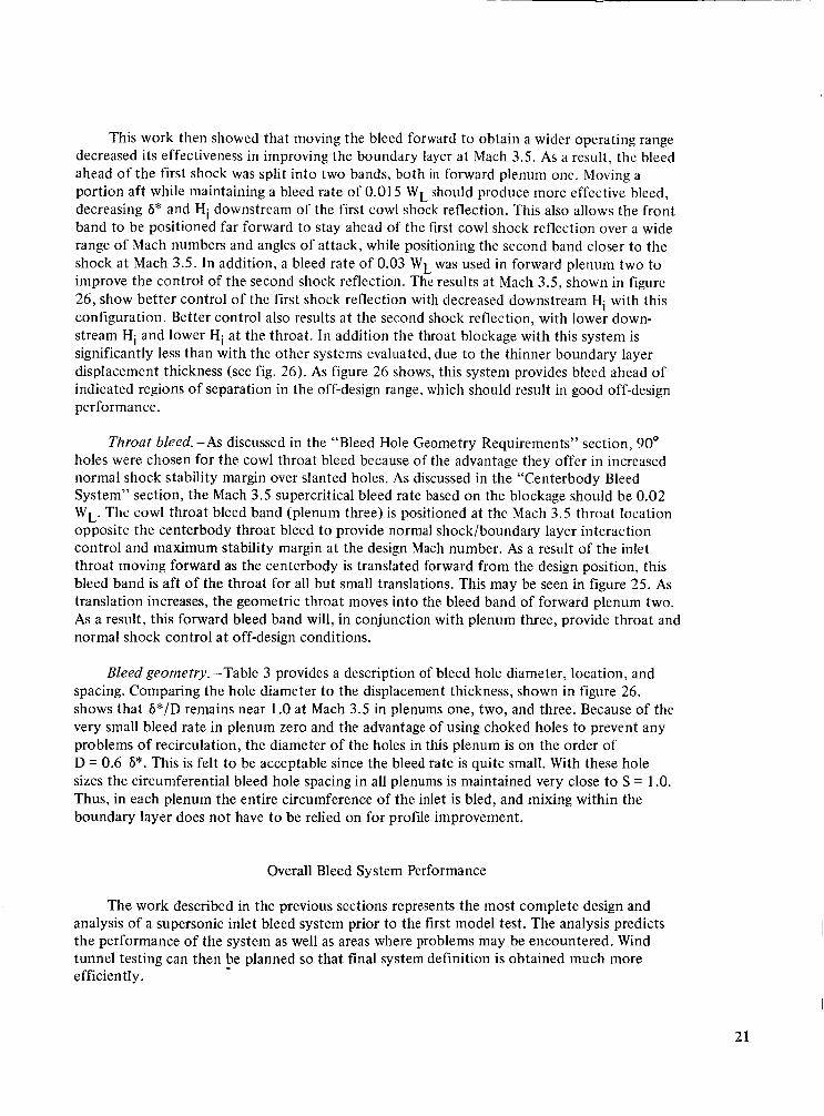
Bleed geometry.-Table 3 provides a description of bleed hole diameter, location, and spacing. Comparing the hole diameter t o the displacement thickness, shown in figure 26, shows that 6*/D remains near 1 .O at Mach 3.5 in plenums one, two, and three. Because of the very small bleed rate in plenum zero and the advantage of using choked holes to prevent any problems of recirculation, the diameter of the holes in this plenum is on the order of D = 0.6 6*. This is felt to be acceptable since the bleed rate is quite small. With these hole sizes the circumferential bleed hole spacing in all plenums is maintained very close to S = 1 .O. Thus, in each plenum the entire circumference of the inlet is bled, and mixing within the boundary layer does not have t o be relied on for profile improvement.
Overall Bleed System Performance
The work described in the previous sections represents the most complete design and analysis of a supersonic inlet bleed system prior to the first model test. The analysis predicts the performance of the system as well as areas where problems may be encountered. Wind tunnel testing can then be planned so that final system definition is obtained much more efficiently.
21
Table 3.-Cowl Bleed Holes
Bleed band Plenum station number
3.83-3.85 0
4.21-4.24 1
4.31 -4.34
4.515-4.585 2
4.66-4.74 3
Number of Number Row I holeshow I of rows 1 station in.
4.217 4.233 0.040 709
Hole area, Spacing, S = Y / D
0.0041 1
0.00592
0.00592
0.01005 1 .oo
22
An illustration of the proposed bleed system bleed hole pattern is shown approximately t o scale on the inlet contours in figure 27. The bleed rates predicted for this system are shown across the started operating Mach number range in figure 28. This figure illustrates that rela- tively high forward bleed rates are maintained at off-design conditions to control the high- pressure-ratio shock system.
The proposed bleed system as described was investigated with the boundary layer analysis throughout the started Mach number range. As discussed previously, only forward bleed has been included in the analysis. The results of the analysis, in the form of centerbody and cowl Hi and 6” maps, are shown in figures 29 through 32. Figure 29 presents a map of boundary layer Hi on the centerbody with the proposed bleed system.
The centerbody boundary layer is predicted t o separate upstream of the throat at several Mach numbers at the relatively strong second or third centerbody shock reflections. As mentioned earlier, the third shock reflection also produces subsonic flow in the reflection for Mach 2.9 and Mach 2.0 to 1.8. These separations are expected to be small, contained within the shock/boundary layer interaction, or reattaching very quickly with rapid boundary layer redevelopment, particularly since for all these cases the bleed system provides for upstream profiles which generally have low Hi, indicating a “full” profile. Additionally, the solutions are generally close t o the throat before separation is encountered. Thus it is expected that these problems will result in little or no degradation of inlet performance.
Figure 29 also shows that there are no regions of excessive profile distortion, high Hi, except behind oblique shock reflections. It may be seen that rapid boundary layer redevelop- ment occurs in these regions, and Hi returns to acceptable levels quite rapidly.
The results for the cowl bleed system are presented in the form of an Hi map in figure 30. The solution stops with a prediction of separation at the relatively strong second cowl shock reflection between Mach 3.4 and 2.8. Since the upstream Hi is quite low over this entire range the separations are expected to be small with rapid redevelopment or be contained within the shock/boundary layer interaction. In addition, the shock reflection is close to the throat, and thus subject to throat bleed control. As a result, little or no degradation of inlet performance is expected. Over the remainder of the started Mach number range, except at Mach 1.6, the solution extends past the cowl throat. The only regions of high Hi are behind shock reflections, and these redevelop rapidly to acceptably low values. The throat profiles are quite good, with low Hi throughout this Mach number range and are probably also satisfactory between Mach 2.8 and 3.4. Near Mach 3.5 the second cowl shock reflection is just ahead of the throat, with resulting high Hi values. Figure 30 illustrates that the downstream redevelop- ment is rapid in this Mach number range. In the actual inlet this shock reflection will be moved forward somewhat due t o cumulative viscous effects. This greater length for redevelop- ment will improve the throat boundary layer Hi. Additionally, cowl throat bleed will be active in this region t o provide profile improvement. Because of these effects, no problems on the cowl throat are expected.
Both the centerbody and cowl show separation at the first shock reflection at Mach 1.6 as shown in figures 29 and 30. This was predicted in the boundary layer analysis without bleed, as previously discussed, but the bleed system was not altered to account for it. If it is found in testing that these separations are significant, it is recommended that the started Mach number range be selected beginning at Mach 1.7.
23
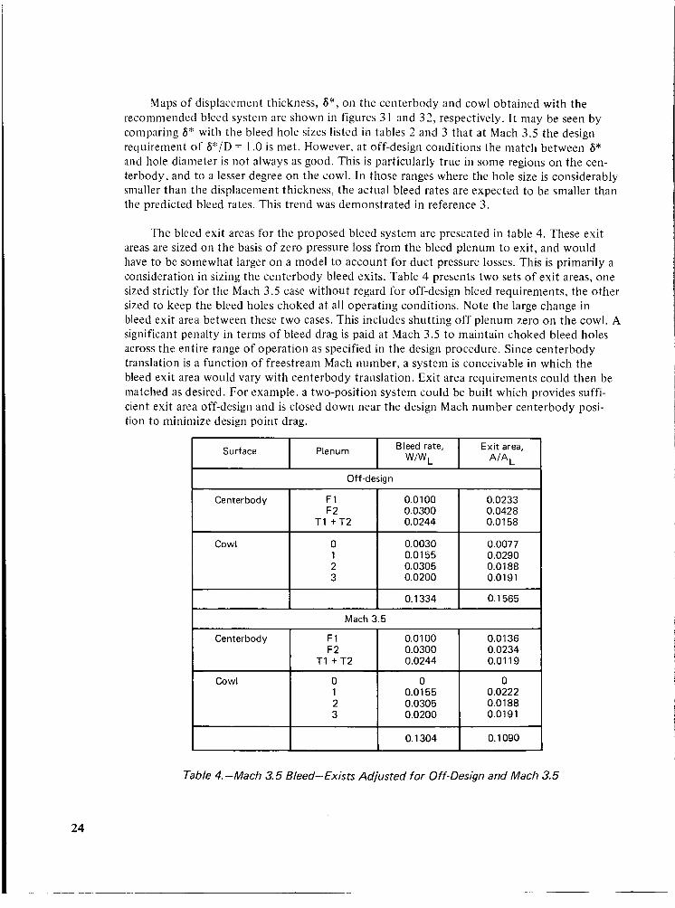
Maps of displacement thickness, 6*, on the centerbody and cowl obtained with the recommended bleed system are shown in figures 31 and 3 2 , respectively. It may be seen by coniparing 6" with the bleed hole sizes listed in tables 2 and 3 that at Mach 3.5 the design requirement of 6*/D = 1 .O is met. However, at off-design conditions the match between 6" and hole diameter is not always as good. This is particularly true i t1 some regions on the cen- terbody, and to a lesser degree on the cowl. In those ranges where the hole size is considerably smaller than the displacement thickness, the actual bleed rates are expected to be smaller than the predicted bleed rates. This trend was demonstrated in reference 3 .
Centerbody
The bleed exit areas for the proposed bleed system are presented in table 4. These exit areas are sized on the basis of zero pressure loss from the bleed plenum t o exit, and would have to be somewhat larger on a model to account for duct pressure losses. This is primarily a consideration in sizing the centerbody bleed exits. Table 4 presents two sets of exit areas, one sized strictly for the Mach 3.5 case without regard for off-design bleed requirements, the other sized to keep the bleed holes choked at all operating conditions. Note the large change in bleed exit area between these two cases. This includes shutting off plenum zero on the cowl. A significant penalty in terms of bleed drag is paid at Mach 3.5 to maintain choked bleed holes across the entire range of operation as specified in the design procedure. Since centerbody translation is a function of freestream Mach number, a system is conceivable in which the bleed exit area would vary with centerbody translation. Exit area requirements could then be matched as desired. For example, a two-position system could be built which provides suffi- cient exit area off-design and is closed down near the design Mach number centerbody posi- tion to minimize design point drag.
F1 0.0100 0.0233 0.0428 F2 0.0300
T I + T 2 0.0244 0.01 58
24
0.0030 0.01 55 0.0305 0.0200
I Bl;;',rpte, I Exit area, AIA, I Surface I Plenum
0.0077 0.0290 0.0188 0.0191
Cowl 0 1 2 3
I I I 0.1 334 0.1 565 - Mach 3.5
Centerbody 0.0136 0.0234
F1 0.0100 F2
T I + T 2 I :::E: I 0.0119
0.01 55 0.0222 0.0305 0.01 88
Table 4.-Mach 3.5 Bleed-Exists Adjusted for Off-Design and Mach 3.5
Alternate Bleed Hole Configurations
Bleed rate, W/WL
0.0100 0.01 50 0.0244
0 0.0078 0.01 53 0.01 33
The purpose of the bleed system design procedure is to reduce the amount of wind tun- nel testing required to develop an optimum bleed system. However, flexibility should be avail- able for “fine tuning” the system in the wind tunnel.
Exit area, AIAL
0.0 136 0.01 17 0.0119
0 0.01 11 0.0094 0.0127
Table 4 presents the proposed system with exits sized to maintain choked holes at all conditions, and with exits sized to maintain choked holes at Mach 3.5. An obvious test varia- tion would be t o test the smaller exit area configuration to determine how adverse the effects are of unchoking bleed holes off-design.
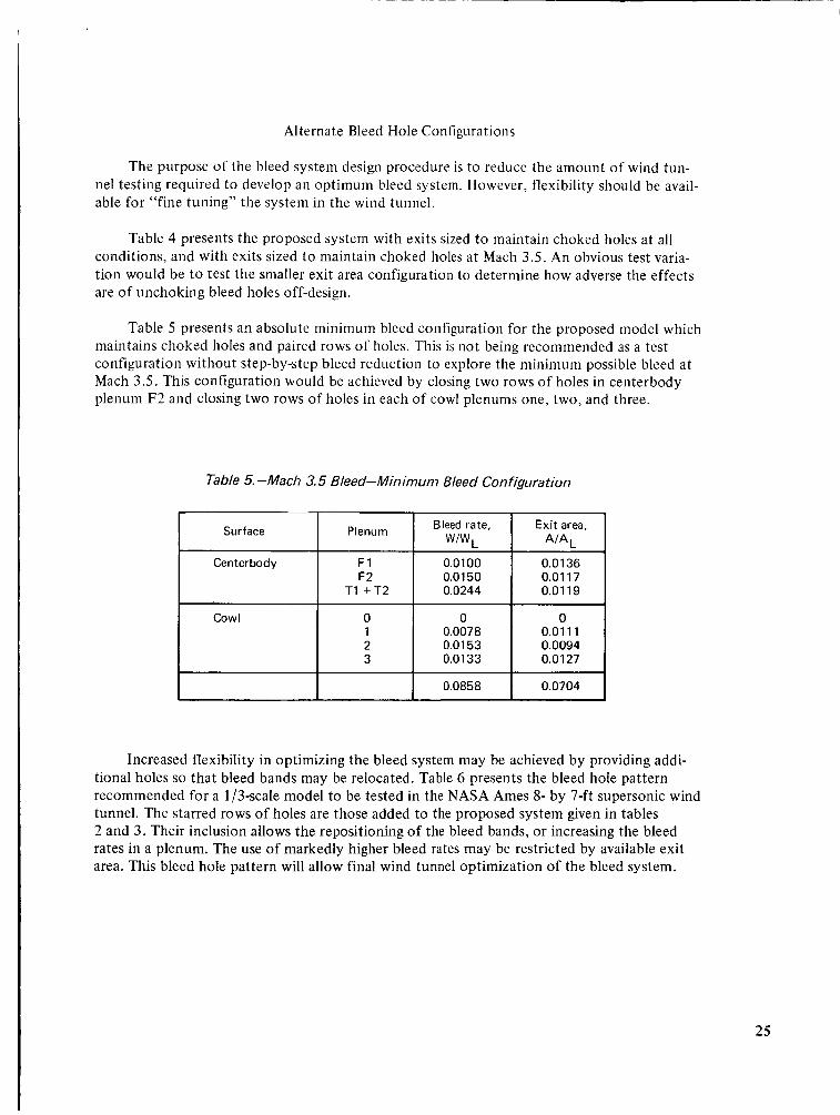
1 1
Table 5 presents an absolute minimum bleed configuration for the proposed model which maintains choked holes and paired rows of holes. This is not being recommended as a test configuration without step-by-step bleed reduction to explore the minimum possible bleed at Mach 3.5. This configuration would be achieved by closing two rows of holes in centerbody plenum F2 and closing two rows of holes in each of cowl plenums one, two, and three.
0.0858 0.0704 I
Table 5. -Mach 3.5 Bleed-Minimum Bleed Configuration
Surface I Centerbody i
~
I
Plenum
F1 F2
T1 + T 2
0 1 2 3
Increased flexibility in optimizing the bleed system may be achieved by providing addi- tional holes so that bleed bands may be relocated. Table 6 presents the bleed hole pattern recommended for a 1 /3-scale model to be tested in the NASA Ames 8- by 7-ft supersonic wind tunnel. The starred rows of holes are those added to the proposed system given in tables 2 and 3. Their inclusion allows the repositioning of the bleed bands, or increasing the bleed rates in a plenum. The use of markedly higher bleed rates may be restricted by available exit area. This bleed hole pattern will allow final wind tunnel optimization of the bleed system.
25
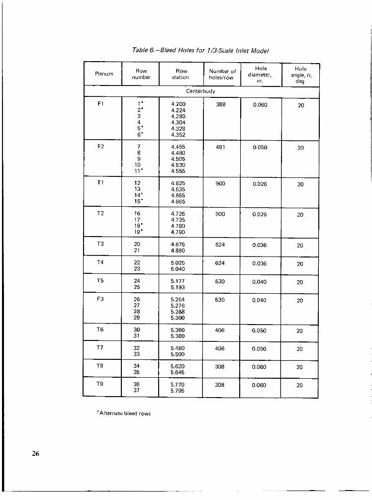
Table 6.-Bleed Holes for 1/3-Scale Inlet Model
Row number Plenum
Hole Hole Number Of diameter, angle, 01,
Row station ho I es/r ow
in. deg
~~
*Alternate bleed rows
Centerbody
4.224 4.280 4.304 4.328 4.352
4.455 4.480 4.505 4.530
4.625 900 4.635 4.655 4.665
4.725 900 4.735 4.780 4.790
4.875 624 4.890
5.025 624 5.040
5.177 530 5.193
5.264 530 5.276 5.288 5.300
5.360 5.380
5.480 5.500
5.620 5.645
5.770 5.795
I *O 0.036
0.036 1 20
1
I 20- 0.040
0.040
0.050
0.050
0.060
0.060 20
26
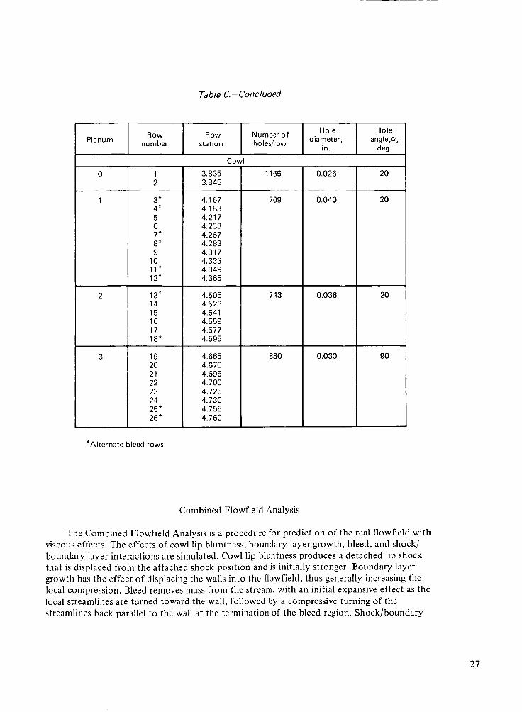
Table 6.-Concluded
Hole
in. Number Of diameter, Row Row
number station ho lesirow Plenum Hole
anglep, d eg
1 3.835 2 3.845
3" 4" 5 6 7" 8" 9
10 11" 12"
13" 14 15 16 17 18"
1165
1 4.167 4.183 ' 4.217
' 4.233 4.267 4.283 4.317 4.333 4.349 4.365
4.665 4.670 4.695 4.700 4.725 4.730 4.755 4.760
4.505 4.523 4.541 4.559 4.577 4.595
880
709
743
24 25" 26 *
0.026
0.040
0.036
0.030
Hole anglep,
d eg
20
20
20
90
*A Iter na te bleed rows
Combined Flowfield Analysis
The Combined Flowfield Analysis is a procedure for prediction of the real flowfield with viscous effects. The effects of cowl lip bluntness, boundary layer growth, bleed, and shock/ boundary layer interactions are simulated. Cowl lip bluntness produces a detached lip shock that is displaced from the attached shock position and is initially stronger. Boundary layer growth has the effect of displacing the walls into the flowfield, thus generally increasing the local compression. Bleed removes mass from the stream, with an initial expansive effect as the local streamlines are turned toward the wall, followed by a compressive turning of the streamlines back parallel to the wall at the termination of the bleed region. Shock/boundary
27

28
layer interactions modify the boundary layer properties, as well as tending t o move the reflec- ted shock forward relative to an inviscid solution. These effects produce significant changes in the flowfield as compared to an inviscid solution.
This analysis is described in detail in reference 5, and is shown there to produce results that agree well with experimental data from large-scale models. Because the use of the Com- bined Flowfield Analysis is time consuming, it is not suited to use as a design tool in the initial steps of defining a bleed system. However, it does lend itself nicely to evaluation of that sys- tem. The use of the Combined Flowfield Analysis in the bleed system design provides a defi- nition of the flowfield with viscous effects included. These results are used to determine whether bleed bands are correctly positioned to allow control of shock interactions and pres- sure gradients. Because of the complexity and time required to apply the analysis, only two cases are considered.
A Combined Flowfield Analysis has previously been applied to an inlet using the 1/3-scale model hardware. Reference 5 presents the results of the analysis for the inlet tested and described in reference 2. This work showed the cowl lip bluntness effect for the 1 /3-scale model t o be negligible, so this effect was not accounted for in the following analyses.
The Combined Flowfield Analysis procedure was applied to the Mach 3.5 inlet with the proposed bleed system at Mach 3.5. The results, in the form of surface pressure distributions and characteristic network and shock patterns, are presented in figure 33. The bleed regions are indicated by the shaded arrows. This figure shows that shock reflections of the primary shock system fall behind or in the aft portion of the bleed bands designed to control those reflections. This means that the bleed bands are correctly positioned, even with viscous effects included. Repositioning of bleed bands to control shock interactions will not be required. Figure 33 shows that the primary shock system is becoming continuously stronger, particu- larly following the first cowl shock reflection. Part of t h s strengthening comes from the shocks off the second and third cowl bleed bands and the second centerbody bleed band. Much of the shock strengthening comes from the distributed compression due to boundary layer growth. The primary oblique shock system is predicted t o have too great a deflection angle to allow a simple reflection with supersonic flow downstream at the second cowl shock reflection. As stated in reference 5, the full significance of this is not presently understood. The deflection angle is too large, by about 1.2q t o allow supersonic flow downstream. In addition, this reflection occurs in a favorable pressure gradient. As a result, it is felt that at worst a small subsonic pocket would exist that would be rapidly accelerated t o supersonic conditions. Further, the Combined Flowfield Analysis done previously in reference 5 for the 1/3scale M = 2.65 inlet tested in reference 2 showed a similar occurrence, but reference 2 shows no problems encountered in the operation of the inlet.
An additional case at Mach 2.7, chosen to be representative of off-design conditions, was computed using the Combined Flowfield Analysis. The results are presented in figure 34. The primary shock system shock reflections are found to be well positioned relative to the bleed bands used to control them. The primary shock system deflection angle is too large to allow a simple oblique shock reflection at the third centerbody shock reflection. As in the Mach 3.5 case the turning is only slightly too great t o allow supersonic flow downstream, and the shock reflection occurs in a region of favorable pressure gradient. Thus, it is felt the situation will be the same as at Mach 3.5, accelerating to supersonic conditions with no significant adverse effect.
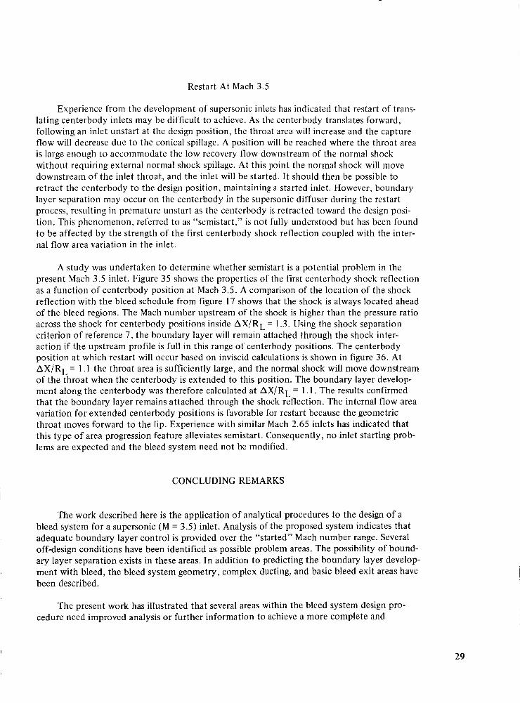
Restart At Mach 3.5
Experience from the development of supersonic inlets has indicated that restart of trans- lating centerbody inlets may be difficult to achieve. As the centerbody translates forward, following an inlet unstart at the design position, the throat area will increase and the capture flow will decrease due to the conical spillage. A position will be reached where the throat area is large enough t o accommodate the low recovery flow downstream of the normal shock without requiring external normal shock spillage. At this point the normal shock will move downstream of the inlet throat, and the inlet will be started. It should then be possible to retract the centerbody to the design position, maintaining a started inlet. However, boundary layer separation may occur on the centerbody in the supersonic diffuser during the restart process, resulting in premature unstart as the centerbody is retracted toward the design posi- tion. This phenomenon, referred to as “semistart,” is not fully understood but has been found to be affected by the strength of the first centerbody shock reflection coupled with the inter- nal flow area variation in the inlet.
A study was undertaken to determine whether semistart is a potential problem in the present Mach 3.5 inlet. Figure 35 shows the properties of the first centerbody shock reflection as a function of centerbody position at Mach 3.5. A comparison of the location of the shock reflection with the bleed schedule from figure 17 shows that the shock is always located ahead of the bleed regions. The Mach number upstream of the shock is higher than the pressure ratio across the shock for centerbody positions inside AXIRL = 1.3. Using the shock separation criterion of reference 7, the boundary layer will remain attached through the shock inter- action if the upstream profile is full in this range of centerbody positions. The centerbody position at which restart will occur based on inviscid calculations is shown in figure 36. At AX/RL = 1 . I the throat area is sufficiently large, and the normal shock will move downstream of the throat when the centerbody is extended to this position. The boundary layer develop- ment along the centerbody was therefore calculated at AX/RL = 1.1. The results confirmed that the boundary layer remains attached through the shock reflection. The internal flow area variation for extended centerbody positions is favorable for restart because the geometric throat moves forward to the lip. Experience with similar Mach 2.65 inlets has indicated that this type of area progression feature alleviates semistart. Consequently, no inlet starting prob- lems are expected and the bleed system need not be modified.
CONCLUDING REMARKS
The work described here is the application of analytical procedures to the design of a bleed system for a supersonic (M = 3.5) inlet. Analysis of the proposed system indicates that adequate boundary layer control is provided over the “started” Mach number range. Several off-design conditions have been identified as possible problem areas. The possibility of bound- ary layer separation exists in these areas. In addition t o predicting the boundary layer develop- ment with bleed, the bleed system geometry, complex ducting, and basic bleed exit areas have been described.
The present work has illustrated that several areas within the bleed system design pro- I I cedure need improved analysis or further information to achieve a more complete and
29
accurate design. These areas and the improvements needed are identified below. While quite comprehensive analytic and isolated experimental work was used to define the bleed system, a large-scale wind tunnel test with the proposed bleed system is needed not only to validate the procedure but to provide valuable experimental data for future bleed system design.
The bleed hole data presently available are limited in terms of variation of bleed hole parameters. The bleed geometry for the proposed bleed system was chosen in part on the basis of existing experimental bleed hole data derived from isolated wind tunnel tests on flat plates with fully developed boundary layers. The bleed hole data presently used are limited in varia- tion of hole diameter, hole length, hole spacing, and upstream boundary layer profile. A comprehensive parametric study of bleed hole performance from isolated tests would be of great value in future inlet design. With the added information the designer could perform tradeoffs not presently possible between the various parameters to arrive at a configuration, and have greater confidence in the accuracy of the design.
At several off-design conditions the possibility of boundary layer separation exists. These separations are, in each case, predicted downstream of shock reflections. The current analysis does not predict the size of separations or the flow behavior within separated regions. On the basis of prior experience with supersonic inlets it is felt that the separations, if they exist, would be small and would not significantly affect inlet performance. The development of the capability to predict interactions with local separation, and to predict flow conditions down- stream if the separation does not immediately reattach, would be of great benefit because interactions of this type may be overcontrolled using current methods. The ability to predict the effect of a local separation on the inlet flowfield would be extremely valuable in deter- mining the amount of boundary layer control required. In addition, the capability to predict the effects of bleed within a shock interaction would be of great help in determining optimum bleed location. Also, analytic understanding of normal shock/boundary layer interactions would allow predictions of throat bleed requirements without reliance on empirical data.
At several off-design Mach numbers, local subsonic flow was predicted. Since the method of characteristics is valid only for supersonic flow, the analytical procedure cannot be applied when any subsonic point is encountered. The analytical procedure would be significantly improved if an analysis were created which allowed computation through and past locally subsonic regions, allowing a more complete analytical design of the bleed system.
The present bleed system design procedure requires a considerable amount of time for data preparation. A significant decrease in the complexity and time required in the procedure could be achieved by modifying the input and output of the boundary layer and inviscid flow programs to make them more compatible. This type of improvement would also make the Combined Flowfield Analysis easier to use for bleed system evaluation. Further work of this kind, plus development of an analysis defining the structure of shock/boundary layer inter- actions, could allow a more automated Combined Flowfield Analysis, thus encouraging greater application in final bleed system evaluation.
The bleed system design procedure in its present form is, however, extremely valuable. Its use has allowed analytical definition of a bleed system incorporating features that are unlikely to evolve from wind tunnel testing. Furthermore, possible problem areas have been
30

identified before testing has been undertaken. The analytical bleed system design procedure is felt to be an important advancement in supersonic inlet design technology and promises to save many wind tunnel testing hours in the development of future supersonic inlet systems.
31
32
APPENDIX
The inlet described in reference 6 was analyzed using the inviscid flow MOCHA program. At each AM,= 0.1 along the translation schedule between Mach 3.5 and Mach 1.6 the inviscid flowfield was computed. Figures 37-56 present the results of the study in the form of plotted surface static pressures, together with the contours, characteristic network, and shock pattern for flowfield visualization.
This analysis revealed that the flowfield solution extended past the throat over most of the Mach number range. Between Mach 2.8 and 3 .3 and between Mach 1.7 and 2.0 the oblique shock system becomes so strong that it produces subsonic flow ahead of the throat. This con- dition may be restricted to a local subsonic pocket.
REFERENCES
1. Design of Bleed Systerns for a N A S A Mz3.5 Inlet, technical proposal, D6-24854, The Boeing Company, March 197 1 .
2. J. L. Koncsek and J . Syberg, Transonic and Supersonic Test of a Mach 2.6.5 Mi.\-ed- Compression Axisymmetric Intake, NASA CR-1977, The Boeing Company.
3. J . Syberg and J. L. Koncsek, Transonic and Supersoriic Test oj’the SST Prototype Air Intake, report FAA-SS-72-50, prepared for FAA by The Boeing Company, April 1972.
4. T. A. Reyhner, A Computer Program f o r Finite-Difference Calculation of Compressible Turbulent Boundary Layers, D6-23236, The Boeing Company, June 17, 1970.
5. T. A. Reyhner and T. E. Hickcox, “A Procedure for Combined Viscous-Inviscid Analysis of Supersonic Inlet Flow Fields,” A I M paper 72-44, January 17, 1972.
6. T. E. Hickcox, Report o f Work Performed Under Contract NAS2-6643, Design of Bleed Systems f o r a NASA M=3.5 Inlet, D6-40559, The Boeing Company, March 28, 1972.
I . G. C . Paynter, Shock and Ramp Induced Incipient Separation of a Turbulent Boundary Layer, D6-11487, The Boeing Company, November 3 , 1967.
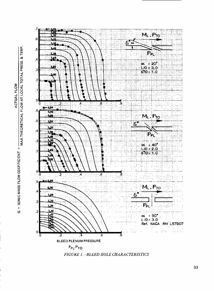
l i I w !- 4 vj v) w K n J
l- a e a s k s $
-1
0
3
U -1
I- w a 0 w I k X
I a
I1
0
33

34
10
8
6
4
2
2.0
1.8
1.6
1.4
1.2
1 .c
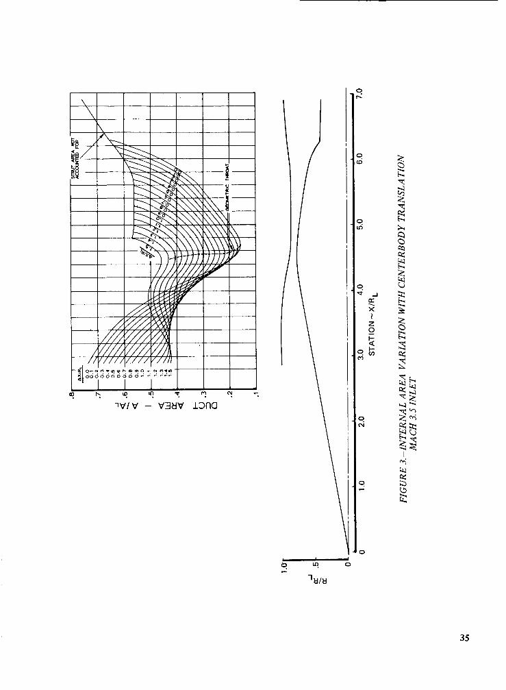
35
37
38
39
41
42
OllVtl3klflSS3tld CINV t138WflN H3VW
Ol lVt l 3tlflSS3tld aNV tl38WnN H3VW
43
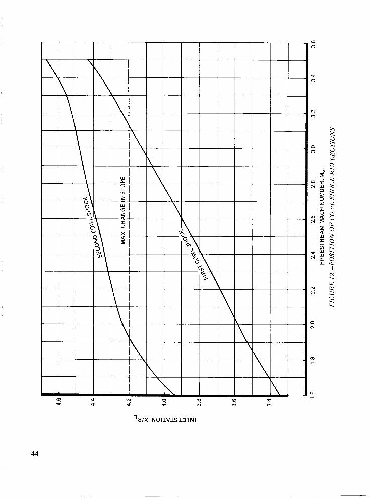
'U/X ' N O I l V l S 131NI
44
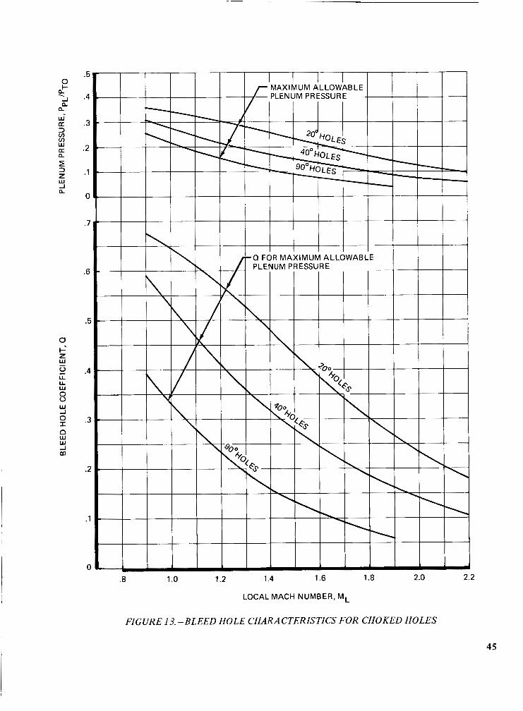
? n
n
1 -1 n
W CT
v) W CT
2 n Zi 3 z W -1 n
U
z w G
0 - LL U w 8 W -I 0 I
w w -1
n
m
.5
.4
.3
.2
.1
0
. I
.E
I
1
LOCAL MACH NUMBER, ML
FIGURE 13.-BLEED HOLE CHARACTERISTICS FOR CHOKED HOLES
45
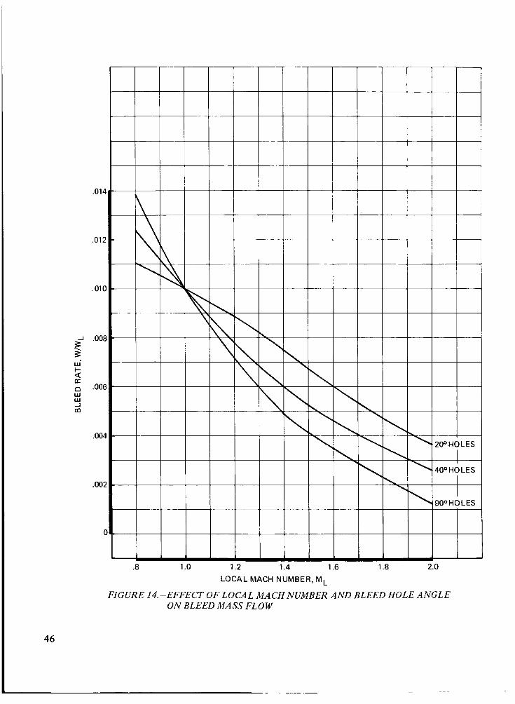
LOCAL MACH NUMBER, ML
FIGURE 14.-EFFECT OF LOCAL MACH NUMBER AND BLEED HOLE ANGLE ON BLEED MASS FLOW
46
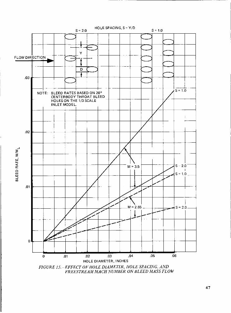
FLOW D I
.03 1
I .02
HOLE SPACING, S = Y/D s = 2.0 s = 1.0
0 .01 .02 .03 .04 .05 .06 HOLE DIAMETER, INCHES
FIGURE 15.-EFFECT OF HOLE DIAMETER, HOLE SPACING, AND FREESTREAM MACH NUMBER ON BLEED MASS FLOW
47
I
48
49
50

.I2
.IO
2 .oa I u - z .06 * Y)
.04
.02
0
2.0
1 .e
1.6
.- I
1.4
1 .i
1 .c
STATION, X/RL
FIGURE 19.-FOR WARD CENTERBODY BLEED REQUIREMENTS A T MACH 3.5
51
O1d/ldd 3 tl rISS3 tld Wn N37d
52
N 9
0 '4 t
3 i
3 0
O*d/ldd 3tlnSS3tld VnN31d ~MIM M O ~ J a3318
53

(D d ru 0 '9 N 9 9 9
'MIM M O l J a3318 "d/ldd 3tlflSS3tld Wf lN3 ld
54
(v
z I 3 z W
0
-I CT X . z- 0 k 6
55

57
v, W I 0 f 1
* Y)
STAT1 ON - X/R ,- FIGURE 26.-FORWARD COWL BLEED REQUIREMENTS ATMACH 3.5
58

4 I 0
5 I-
I-
0 CT I I-
a
a a
\ 0 m o - m 0 8 =
59
61
62
63
64
* ' Lo
ru' cr,
65
66
-I CC X
l- >
. E-
a 2 CC w I- z w u H
U w V z 2 c a
- c r 0
a
a
2 a a n
Q 0
z I 0
2 H w n I-
3
z c -. c)
t CC w n 3 cn cn w CC n Y u 0 5
5.:
5.(
4.1
4.1
4..
4.:
4s
3.t
5.(
4.t
3.c
2.c
1 .o
0
/
.2 .4 .6 .8 1 .o 1.2 1.4 CENTERBODY TRANSLATION, X/RL
FIGURE 35.-FIRST CENTERBODY SHOCK REFLECTION PROPER TIES DURING R E S T A R T A T M A C H 3.5
67
c
5 oc' m 5 3 z I 0
z
w
a
hl H oc' m 5 3 z I u H
w
a
0 a a a a
l-
w [r
3.3
3.2
3.1
.5
.4
2.0
1.8
1.6
1.4
1.2
1 .c .8 .9 1 .o 1.1 1.2 1.3 1.4
CENTER BODY TRANSLATI ON, X/RL
FIGURE 36.-MACH 3.5 RESTART POSITION
68
69
71
72
13

74
75
77
78

79
80
81
83
__ ..
84
85
86
87
88
Related Documents