BIOMETRIC VOTING MACHINE “BIOMETRIC VOTING MACHINE” A Report submitted to MSRIT Bangalore For partial requirement of award of degree of Bachelor of Engineering in Electronics and Communication By KARTHIK DATT A 1MS08EC402 VISHWANATH BAGALKOT 1MS07EC119 MANJUNATHA D 1MS08EC403 THILAK BABU KS 1MS08EC409 Under the guidance of Mr. C.G.RAGHAVENDRA, Assistant Professor M.S.R.I.T, Bangalore-54 DEPARTMENT OF ELECTRONICS AND COMMUNICATION ENGG MS RAMAIAH INSTITUTE OF TECHNOLOGY (Autonomous Institute, Affiliated to VTU) May 2011 Dept of ECE, MSRIT, Bangalore

Welcome message from author
This document is posted to help you gain knowledge. Please leave a comment to let me know what you think about it! Share it to your friends and learn new things together.
Transcript
BIOMETRIC VOTING MACHINE
“BIOMETRIC VOTING MACHINE”
A Report submitted to
MSRIT
Bangalore
For partial requirement of award of degree of
Bachelor of Engineering in Electronics and Communication
By
KARTHIK DATT A 1MS08EC402
VISHWANATH BAGALKOT 1MS07EC119
MANJUNATHA D 1MS08EC403
THILAK BABU KS 1MS08EC409
Under the guidance of
Mr. C.G.RAGHAVENDRA, Assistant Professor
M.S.R.I.T,Bangalore-54
DEPARTMENT OF ELECTRONICS AND COMMUNICATION ENGG
MS RAMAIAH INSTITUTE OF TECHNOLOGY
(Autonomous Institute, Affiliated to VTU)
May 2011
Dept of ECE, MSRIT, Bangalore
BIOMETRIC VOTING MACHINE
CHAPTER 1
INTRODUCTION
INTRODUCTION:
Dept of ECE, MSRIT, Bangalore
BIOMETRIC VOTING MACHINE
The objective of voting is to allow voters to exercise their right to
express their choices regarding specific issues, pieces of legislation,
citizen initiatives, constitutional amendments, recalls and/or to choose
their government and political representatives. Technology is being used
more and more as a tool to assist voters to cast their votes. To allow the
exercise of this right, almost all voting systems around the world include
the following steps:
voter identification and authentication
voting and recording of votes cast
vote counting
publication of election results
Voter identification is required during two phases of the electoral
process: first for voter registration in order to establish the right to vote
and afterwards, at voting time, to allow a citizen to exercise their right to
vote by verifying if the person satisfies all the requirements needed to
vote (authentication).
Ancient archeological artifacts and historical items have been
discovered to still retain a large number of fingerprints on them. Since this
was a discovered significant stride in fingerprinting and identification have
been made. In 1788 a detailed description of anatomical formations of
fingerprints was made. Then in1823 fingerprints began to be classified
into nine categories, (Handbook) and by the 19th century Sir Francis
Galton had developed analytical methods for fingerprint matching. As the
criminal justice system evolved, there arose the need for criminals to be
uniquely identified by some physically identifiable trait. Richard Edward
Henry of Scotland Yard began using fingerprinting in 1901 and its success
eventually lead to its increased use in the law enforcement field
The field of biometrics was formed and has since expanded on to
many types of physical identification. Still, the human fingerprint remains
a very common identifier and the biometric method of choice among law
enforcement. These concepts of human identification have lead to the
development of fingerprint scanners that serve to quickly identify
individuals and assign access privileges. The basic point of these devices
Dept of ECE, MSRIT, Bangalore
BIOMETRIC VOTING MACHINE
is also to examine the fingerprint data of an individual and compare it to a
database of other fingerprints.
Nearly everyone in the world is born with a fingerprint that is
unique; a separate and comprehensively identifying attribute that sets us
apart from the other 6.5 billon people that inhabit this world. It is because
of this fact that the fingerprint has proven such a useful part of biometric
security. The very reason that fingerprint scanners are useful can be
found in this fact as well. However, this is far from the only reason they
are used.
Another important reason fingerprint scanners are used is, they
provide a quick, easy, efficient, and secure measure through which, an
individual with the proper access privileges can authenticate. The
fingerprint of an employee for example, is stored in a database that the
scanner queries every time it is used. There are two basic Boolean
conditions the scanner then goes through when an individual’s print is
scanned. First, the print is usually searched for in a database of
fingerprints, once it is found it then looks at the print to see what access
privileges are associated with the print and compares them to the access
they are trying to gain. If everything checks out the subject is allowed
access and they are not otherwise. In any case, a log of the event is
usually stored for security purposes the size of these devices is another
reason they have become so mainstream recently. Fingerprint scanners
can be deployed directly near a door for access or as a peripheral to a
computer for logging in. Modern day scanners have even been embedded
on computer keyboards, mice, and USB devices because engineers have
been able to reduce their size. Fingerprint scanners are also very versatile
in the function that they can serve. The most common use may be for
access restriction; however, they have served as time clocks, personal
data retrievers, and even to cut down on truancy in some schools. Since
they have experienced so much success in these areas, businesses are
expanding upon their use and they are getting more public exposure
Dept of ECE, MSRIT, Bangalore
BIOMETRIC VOTING MACHINE
Finger printing recognition, the electronic methods of recording and
recognizing an individual finger print, advanced substantially during the
last decade of the 21th century. Today, identification can be achieved in a
few seconds with reasonable accuracy. As a result, the use of automated
fingerprint identification systems (AFIS) that record, store, search, match
and identify finger prints is rapidly expanding. AFIS can be integrated with
a microcontroller and other peripherals to form an embedded system
which is a comprehensive electronic voting machine with fingerprint print
identification system.
CHAPTER 2
BLOCK DIAGRAM
Dept of ECE, MSRIT, Bangalore
BIOMETRIC VOTING MACHINE
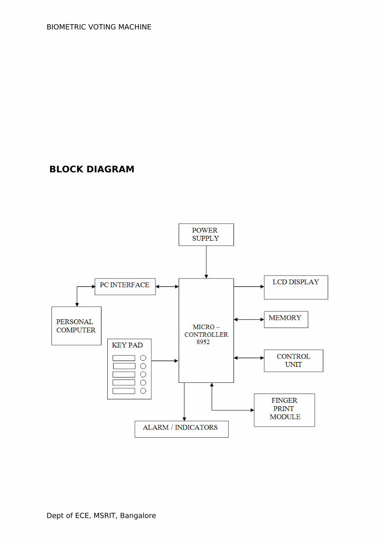
BLOCK DIAGRAM
Dept of ECE, MSRIT, Bangalore
BIOMETRIC VOTING MACHINE
CHAPTER 3
HARDWARE DESCRIPTION:
Dept of ECE, MSRIT, Bangalore
BIOMETRIC VOTING MACHINE
HARDWARE DESCRIPTION:
Biometric Voting Machine hardware mainly contains a
microcontroller, finger print module, eeprom, lcd display, PC interface,
power supply, key pad. Each of the components are described below.
3.1:MICROCONTROLLER- AT89C52:
The 8952 microcontroller is upgraded version of 8051 family of microcontrollers. The 8051 microcontroller was introduced by Intel Corporation in the year 1981. It is an 8-bit microcontroller with Harvard Architecture manufactured by advanced CMOS processes. It has 128 bytes of on chip RAM, 4k bytes of on chip ROM, two 16-bit timers/counters, four 8-bit ports of which one is a serial port, etc. There are 6 interrupt sources also.
Since this is an 8-bit micro controller, the CPU can work on only 8
bits of data at a time. Data larger than 8 bits has to be broken down to 8
bit pieces. Though it has an addressing capability of 64 Kbytes, only 4k
bytes have been provided on chip.
8051 is available in different memory types, such as UV-EPROM,
FLASH, and NV-RAM. The UV-EPROM version of 8051 is the 8751. This chip
has only 4K bytes of on chip UV-EPROM. To use this chip for development
requires access to a PROM burner, as well as a UV-EPROM eraser to erase
all the contents of UV-EPROM inside the 8751 chip before you can
program it again. It takes about 20 minutes to erase the 8751 before it
can be programmed again. This led to introduce FLASH and NV-RAM
versions of 8051.
Dept of ECE, MSRIT, Bangalore
BIOMETRIC VOTING MACHINE
Another popular version of 8051 is DS5000 chip from Dallas
Semiconductor. The on chip ROM is in the form of NV-RAM. The read/write
capability of NV-RAM allows the program to be loaded into the on chip
ROM while in the system. This can be done via a serial port of a PC.
Another advantage of NV-RAM is the ability to change the ROM contents
one byte at a time. The entire ROM must be erased before programmed
again in the case of UV-EPROM and flash memory.
There are also OTP (One Time Programmable) versions of the 8051
available from different sources. Flash and NV-RAM versions are typically
used for product development. When a product is designed and finalized,
the OTP version of the 8051 is used for mass production since it is much
cheaper in terms of price per unit.
There are two other members in the 8051 family of microcontrollers.
They are the 8052 and the 8031.The 8052 has all the standard features of
the 8051 in addition to an extra 128 bytes of RAM, an extra timer, extra
4K bytes of on chip ROM, and two more interrupt sources. Therefore all
programs written for 8051 will run on 8052, but the reverse is not true.
8031 is often referred to as ROM-less 8051 since it has 0K bytes of
on chip ROM. To use this chip we must add external ROM to it. The ROM
containing the program attached to the 8031 can be as large as 64K
bytes. For adding external ROM two ports are needed out of 4 ports,
leaving only 2 ports for I/O operations. To solve this, external I/O ports like
8255 can be added to 8031. Atmel Corporation’s AT89C52is a low-power,
high-performance CMOS 8-bit microcomputer with 8K bytes of Flash
programmable and erasable read only memory (PEROM). The device is
manufactured using Atmel’s high-density nonvolatile memory technology
and is compatible with the industry-standard MCS-51 instruction set and
pin out. The on-chip Flash allows the program memory to be
reprogrammed in-system or by a conventional on volatile memory
programmer. By combining a versatile 8-bit CPU with Flash on a
monolithic chip, the Atmel AT89C52 is a powerful microcomputer that
Dept of ECE, MSRIT, Bangalore
BIOMETRIC VOTING MACHINE
provides a highly flexible and cost-effective solution to many embedded
control applications.
Flash memory can be erased in seconds compared to 20 minutes
needed for 8751. For this reason 89C52 is used in place of 8751 to
eliminate the waiting time needed to erase the chip and thereby speed up
the development time. The development system requires a ROM burner
that supports flash memory. The entire contents of ROM should be erased
in order to program it again; the PROM burner itself does this. The 89C52
Flash reliably stores memory contents even after 10,000 erase and
program cycles. AT89C52 is a popular chip of this category from Atmel
Corporation.
The micro-controller generic part number actually includes a whole family of
microcontrollers that have numbers ranging from 8031 to 8751 and are available in N-
channel Metal Oxide Silicon (NMOS) and CMOS construction. 89c52 is an 8-bit micro-
controller having 40 pins arranged as DIP packages. The features unique to micro-
controllers include:
INTERNAL RAM AND ROM
I/O PORTS WITH PROGRAMMABLE PINS
TIMERS AND COUNTERS
SERIAL DATA COMMUNICATION
The 89C52 architecture consists of these specific features:
Eight-bit CPU with registers A and B
16-bit program counter and data pointer
8-bit stack pointer
Dept of ECE, MSRIT, Bangalore
BIOMETRIC VOTING MACHINE
Internal ROM of 8k
Internal RAM of 128 bytes
Four register banks each containing eight registers
16 bytes addressable at the bit level
80 bytes of general purpose data memory
32 input/output pins arranged as four 8 bit ports
Three 16-bit timer/counter
Full duplex serial data receiver/transmitter
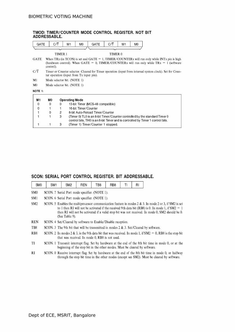
Control registers: TCON, TMOD, SCON, PCON, IP and IE
Two external and three internal interrupt sources
Oscillator and clock circuits
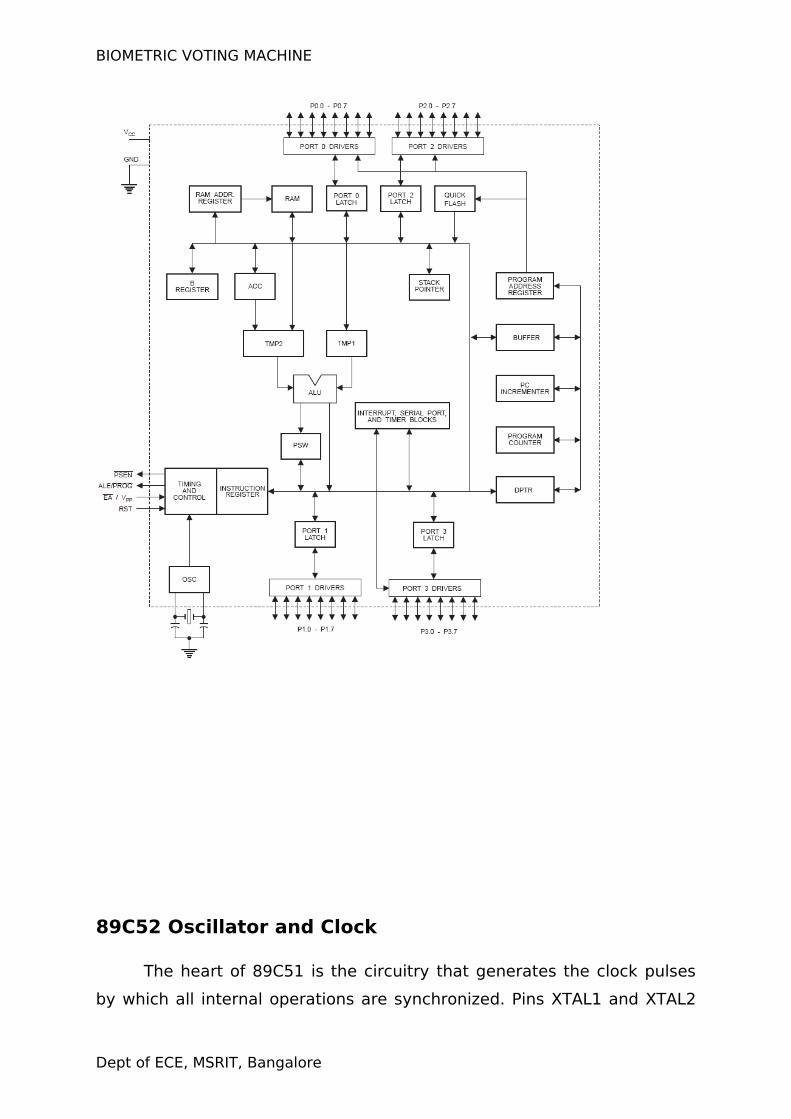
3.1.1:The internal layout of an 89C52:
Dept of ECE, MSRIT, Bangalore
BIOMETRIC VOTING MACHINE
89C52 Oscillator and Clock
The heart of 89C51 is the circuitry that generates the clock pulses
by which all internal operations are synchronized. Pins XTAL1 and XTAL2
Dept of ECE, MSRIT, Bangalore
BIOMETRIC VOTING MACHINE
are provided for connecting a resonant network to form an oscillator. The
crystal frequency is the basic internal clock frequency of the micro
controller.
Program Counter and Data Pointer
The 89C52 contains two 16 bit registers, the program counter and
the data counter. Each is used to hold the address of byte in memory.
Program instruction byte is fetched from location in memory that is
addressed by the PC. The PC is automatically incremented after every
instruction bytes fetched and may also be altered by certain instructions.
The DPTR register is made up of two 8-bit registers named DPH and
DPL, which are used to furnish memory addresses for internal and
external code access and external access. The DPTR is under the control
of program instructions.
A & B CPU registers:
The A and B register holds results of many operations, particularly
math and logical operations. The A register is also used for all data
transfers between the 89C51 and any external memory.
Flags & Program Status Word:
Flags are 1 bit registers provided to store the result of certain
program instructions. The flags are groups inside the program status word
and the power control (PCON) registers. The 89C52 have four math flags
that respond automatically to the result of math operation and three
general-purpose user flags that can be set to 1 or cleared to 0 by the
programmer as desired. The math flag include carry (C), Auxiliary Carry
(AC), Overflow (OV) and Parity (P). User flags are named F0, GF0 and GF1;
they are general purpose flags hat may be used by the programmer to
record some event in the program.
Dept of ECE, MSRIT, Bangalore
BIOMETRIC VOTING MACHINE
The program status word contains the math flag, user program flag
F0, and the register select bits identify which of the four general purpose
register banks is currently in use by the program.
Internal Memory:
The 89C52 have internal RAM for program code bytes and for
variable data that can be altered as the program runs. Additional memory
can be added externally using suitable circuits. Unlike micro-controller
with a Von Neumann architecture, which can use a single memory
address for either program code or data, but not for both, the 89C52 have
Harvard architecture, which uses the same address, in different
memories, for code and data. Internal security accesses the correct
memory based on the nature of operation in progress.
Internal RAM:
It had 128 internal RAM, which is organized, into distinct areas. 32
bytes from address 00H to 1FH that make up thirty two working registers
organized as four bands of eight registers each. A bit addressable area of
sixteen bytes occupies ram byte addresses 20H to 2FH. A general purpose
RAM area above the bit area from 30H to 7FH addressable as bytes.
Stack and Stack Pointer:
The stack refers to an area of internal ram that is used in
conjunction with certain op codes to store and retrieve data quickly. The
eight-bit stack pointer register is used to hold an internal ram address
called the top of the stack. The address held in the SP register is the
location in the internal ram where the last byte of data was stored by a
stack operation.
When data is to be placed on the stack the SP increments before
storing data on the stack up grows, as data is stored. As data is retrieved
from the stack, the byte is read from the stack, and then the SP
decrements to point to the next available byte of stored data. The SP is
Dept of ECE, MSRIT, Bangalore
BIOMETRIC VOTING MACHINE
set to 07H when the 89C52 is reset and can be changed to any internal
ram addressed by the programmer.
Special Function Registers:
The 89C52 operations that do not use the internal ram address from
00H to 7FH are done by a group of specific internal registers each called
special function registers, which may be addressed much like internal
ram, using addresses from 8011 to FFH. Some SFR’s are also bit
addressable. This feature allows the programmer to change only what
needs to be altered, leaving the remaining bits in that SFR unchanged.
Input/ Output pins, Ports and Circuits:
One major feature of a micro-controller is the versatility built into
the IO circuits that connect the 89C52 to external world. Four ports are
provided in 89C52 to connect to the outside world. Different functions are
associated with a single port. The function of a port is decided by a
hardware circuit connected and software commands used to program it
under the complete control of a program designer.
Each port has a D type output latch for each pin. The SFR of each
port are made up of these eight latches, which can be addressed at the
SFR address for that port. The port latch should not be confused with the
port pins. The data on the latch does not have to be the same as that on
the pins. The status of each latch may be read from a latch buffer; while
an input buffer is connected directly to each pin status may be read
independently of the latch state. Different op codes accesses the latch or
pin states as appropriate. Port operation is determined by manner in
which microcontroller is connected to the external circuitry.
The two data paths are shown in figure while circuits that read the
latch or pin data using two entirely separate buffers. The output buffer is
Dept of ECE, MSRIT, Bangalore
BIOMETRIC VOTING MACHINE
enabled when the latch data is read and the lower buffer when the pin
state is read.
Programmable port pins have completely different alternate
functions. The configuration of the control circuitry between the output
latch and the port pins determines the nature of any particular port pin
function. Only one port cannot have alternate function. Port 0, 2, 3 can be
programmed.
Port0: serves as input/output or bidirectional lower order address and data
bus for external memory.
Port1: have no dual functions. It can be used as input/output.
Port2: serves as input/output or bidirectional higher order address and
data bus for external memory.
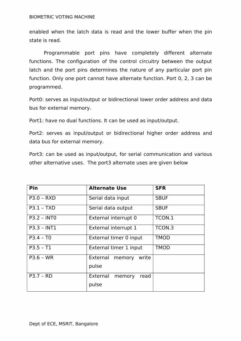
Port3: can be used as input/output, for serial communication and various
other alternative uses. The port3 alternate uses are given below
Pin Alternate Use SFR
P3.0 – RXD Serial data input SBUF
P3.1 – TXD Serial data output SBUF
P3.2 – INT0 External interrupt 0 TCON.1
P3.3 – INT1 External interrupt 1 TCON.3
P3.4 – T0 External timer 0 input TMOD
P3.5 – T1 External timer 1 input TMOD
P3.6 – WR External memory write
pulse
P3.7 – RD External memory read
pulse
Dept of ECE, MSRIT, Bangalore
BIOMETRIC VOTING MACHINE
3.1.2:Counters and Timers:
Many microcontroller applications require the counting of external
events such as frequency of pulse train, or the generation of precise
internal time delays between computer actions. Three sixteen bit counters
named T0,T1and T2 are provided for general use of the programmer. Each
counter may be programmed to count internal clock pulses acting as a
timer or program to count external pulses as a counter.
The counters are divided into eight bit registers called the timer low
(TL0, TL1) and high (TH0, TH1) bytes. All counter actions is controlled by
bit status in the timer mode control registers TMOD, the timer/counter
control register TCON, and certain program instructions.
TMOD is dedicated entirely to the timer and can be considered to be
two duplicate 4 bit registers, each of which controls the action of one of
the timer. TCON has the control bits and flags for the timer in the upper
nibble, control bits and flags for external interrupts in the lower nibble.
Timer Counter Interrupts:
The timers have been included on the chip to relieve the processor
of timing and counting chores. When the program wished to count a
certain number of internal pulses or external events, a number is placed
in one of the counters. The number represents the maximum count less
the decide count, plus 1.The counter increments from the initial number
to the maximum and then roles over to 0 on the final pulse and also set a
timer flag. The flag condition may be tested by an instruction to tell the
program that the count has been accomplished, or the flag may be used
to interrupt the program.
Dept of ECE, MSRIT, Bangalore
BIOMETRIC VOTING MACHINE
Timing:
If a counter is programmed to be a timer, it will count the internal
clock frequency of the oscillator divided by 12d. The resultant timer clock
is gated to the timer. The bit TRX in the TCON register must be set to one
(timer run), and the gate counter is configured as a timer, then the timer
pulses are gated to the counter by the bit and gate bit or the external
input bits INT.
Timer Modes of Operation:
The timers may be operated in one of the four modes that are
determined by the mode bits. M1 and M0 in the TMOD register.
Timer mode 0:
Setting timer X mode bits to 00B in the TMOD register results in
using the THX register as an eight bit counter and TLX as a five bit
counter; pulse input is divided by 32d in TL so that the TH counts the
original oscillator reduced by a total 384d.
Timer mode 1:
Mode 1 is similar to mode 0 except TLX is configures as a full 8 bit
counter, When the mode bits are set to 01B in the TMOD. The timer flag
would be set in 1311 seconds using a 6MHz crystal.
Timer mode 2:
Setting the mode bits to 10b in the TMOD configures the timer to
use only the TLX counter as an eight bit counter. THX is used to hold a
value that is loaded into TLX every time TLX overflows from FFh to 00h.
The timer flag is also set when TLX overflows. This mode exhibits and
auto reloaded feature: TLX will count up from the number in THX,
overflow, and be initialized again with the contents of THX.
Timer mode 3:
Dept of ECE, MSRIT, Bangalore
BIOMETRIC VOTING MACHINE
Timer 0 and 1 may be programmed to be in mode 0.1,2
independently of a similar mode for the other timer. This is not true for
mode3; the timer does not operate independently if mode 3 is chosen for
timer0. Placing timer 1 in mode3 causes it to stop counting; the control bit
TRI and the timer flag TF1 are then used by timer 0. Timer 0 in mode 3
becomes two completely separate eight bit counters. TL0 is controlled by
the gate arrangement and sets the timer flag TF0 whenever it overflows
from FFh to 00h. TH0 receives the timer clock (the oscillator divided by
12) under the control of TRI only and set the TF1 flag when it overflows.
Timer 1 may be still used in modes 0,1 or 2 while timer 0 is on
mode 3 with one important exception: the timer 1 will generate no
interrupts while timer 0 is using the TF1 overflow flags. Switching timer 1
to mode 3 will stop it and hold whatever count is in timer1.
Counting:
The only difference between counting and timing in the source of
the clock pulses when used as a timer, the clock pulses are sourced from
the oscillator through the divide by 12d circuit: when use as counter pint
T0 supplies pulses to counter 0 and pin T1 to counter1. Each high and low
states of the input pulse must be held constant for at least one machine
cycle to ensure reliable counting.
Interrupts:
Interrupts are hardware signals that force a program to call a
subroutine. Interrupts take up the processor time only when the action by
the program is needed. Interrupts are often the only way in which real
time programming can be done successfully.
Interrupts may be generated by internal chip operation or by
external sources. Any interrupt can cause the microcontroller to perform a
hardware call to an interrupt handling subroutine that is located at a pre
determined absolute address in the program memory. Five interrupts are
provided in the 8051. Three of these are generated automatically by
Dept of ECE, MSRIT, Bangalore
BIOMETRIC VOTING MACHINE
interrupt (R1 or T1). Two interrupts are triggered by external signals
provided by circuitry that is connected to pins INT0 and INT1.
All interrupts are under the control of the program. The programmer
is able to alter the control bits in the Interrupt Enable register (IE), the
Interrupt Priority register (IP) and the Timer Control register (TCON). The
program can block all or any of the combinations of the interrupt from
acting on the program by suitable setting or clearing of these registers.
After the interrupts has been handled by the interrupt subroutine, which is
placed by the programmer in the interrupt location in the program
memory, the interrupt program must resume operation at the instruction
where the interrupt take place. Program resumption is done by storing the
interrupted PC address on the stack in ram before changing the PC to the
interrupt address in ROM. The PC address will be stored from the stack
after an RETI instruction is executed at the end of the interrupt
subroutine.
Timer Flag Interrupt:
When a counter/timer slashes overflow, the corresponding timer flag
TF0 or TF1 is set to one. The flag is cleared to 0 when the resulting
interrupt generates a program call to the appropriate timer subroutine in
the memory.
External Interrupts:
Pins INT0 and INT1 are used by external circuitry. Inputs on these
pins can set the interrupt flags IE0 and IE1 in the TCON register to 1 by
two different methods. The IEX flag may be set when the INTX pin reached
a low level or the flags may be set when a high to low transition takes
place on the INTX pin. Bits INT0 and INT1 in TCON program the INTX pins
for low level interrupt when set to 0 and program the INTX pins for
transition interrupt when set to 1. Flags IEX will be reset when the
processor accepts the transition generated interrupt and the interrupt
Dept of ECE, MSRIT, Bangalore
BIOMETRIC VOTING MACHINE
subroutine is accessed. The external circuits must remove the low level
before an RETI is executed.
Reset:
This can be considered as the ultimate interrupt as the program
cannot block the action of the voltage at the RST pin. This type of
interrupt is often called non maskable interrupt (NMI). Unlike other
interrupts, the PC is not stored for later program resumption.
Interrupt Control:
The IE register holds the programmable bits that can enable or
disable all the interrupts as a group, or if the group is enabled, each
individual interrupt source can be enabled or disabled. The IP register bits,
may be set by the program to assign priorities among the various
interrupts sources so that more important interrupts can be serviced first.
3.2:SM630 FINGERPRINT MODULE
Dept of ECE, MSRIT, Bangalore
BIOMETRIC VOTING MACHINE
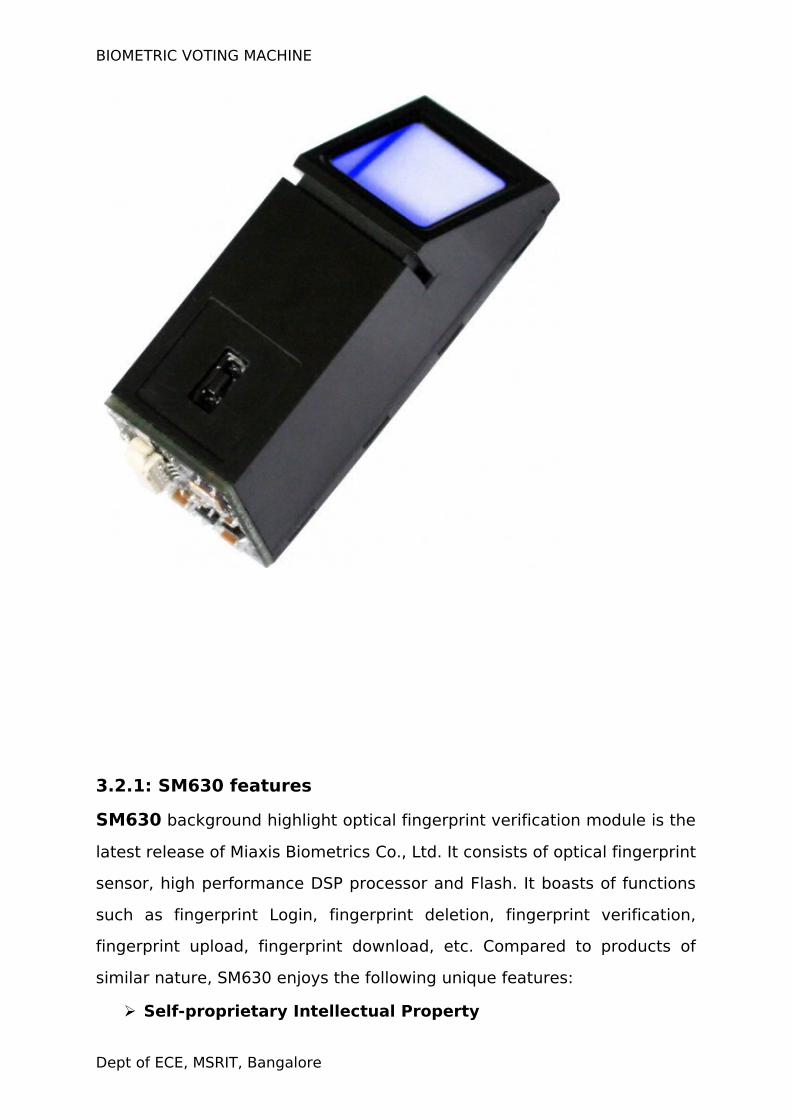
3.2.1: SM630 features
SM630 background highlight optical fingerprint verification module is the
latest release of Miaxis Biometrics Co., Ltd. It consists of optical fingerprint
sensor, high performance DSP processor and Flash. It boasts of functions
such as fingerprint Login, fingerprint deletion, fingerprint verification,
fingerprint upload, fingerprint download, etc. Compared to products of
similar nature, SM630 enjoys the following unique features:
Self-proprietary Intellectual Property
Dept of ECE, MSRIT, Bangalore
BIOMETRIC VOTING MACHINE
Optical fingerprint collection device, module hardware and fingerprint
algorithm are all self developed by Miaxis.
High Adaptation to Fingerprints
When reading fingerprint images, it has self-adaptive parameter
adjustment mechanism, which improves imaging quality for both dry and
wet fingers. It can be applied to wider public.
Low Cost
Module adopts Miaxis’ optical fingerprint collection device, which
dramatically lowers the overall cost.
Algorithm with Excellent Performance
SM630 module algorithm is specially designed according to the image
generation theory of the optical fingerprint collection device. It has
excellent correction & tolerance to deformed and poor-quality fingerprint.
Easy to Use and Expand
User does not have to have professional know-how in fingerprint
verification. User can easily develop powerful fingerprint verification
application systems based on the rich collection of controlling command
provided by SM630 module. All the commands are simple, practical and
easy for development.
Low Power Consumption
Operation current <80mA, specially good for battery power occasions.
Integrated Design
Fingerprint processing components and fingerprint collection components
are integrated in the same module. The size is small. And there are only 4
cables connecting with HOST, much easier for installation and use.
Perfect Technical Support
Miaxis is the leading company in the fingerprint verification industry. It
Dept of ECE, MSRIT, Bangalore
BIOMETRIC VOTING MACHINE
has an excellent customer service team ready to offer powerful technical
support in user development.
3.2.2: TECHNICAL SPECIFICATIONS:
Operating Voltage:
4.3V~6V
Rating Voltage:
6.5V(exceeding this value will cause permanent damage to the module)
Operating Current:
<80mA(Input voltage 5V)
Fingerprint Template:
768 templates
Search Time:
<1.5s(200 fingerprint, average value in test)
Power-on Time:
<200ms(Time lapse between module power-on to module ready
to receive instructions)
Tolerated Angle Offset:
±45°
User Flash Memory:
64KByte
Interface Protocol:
Standard serial interface (TTL level)
Communication Baud Rate:
57600bpsOperating Environment:
Temperature: -10 °C~+40°C
Relative humidity: 40%RH~85%RH(no dew)
Dept of ECE, MSRIT, Bangalore
BIOMETRIC VOTING MACHINE
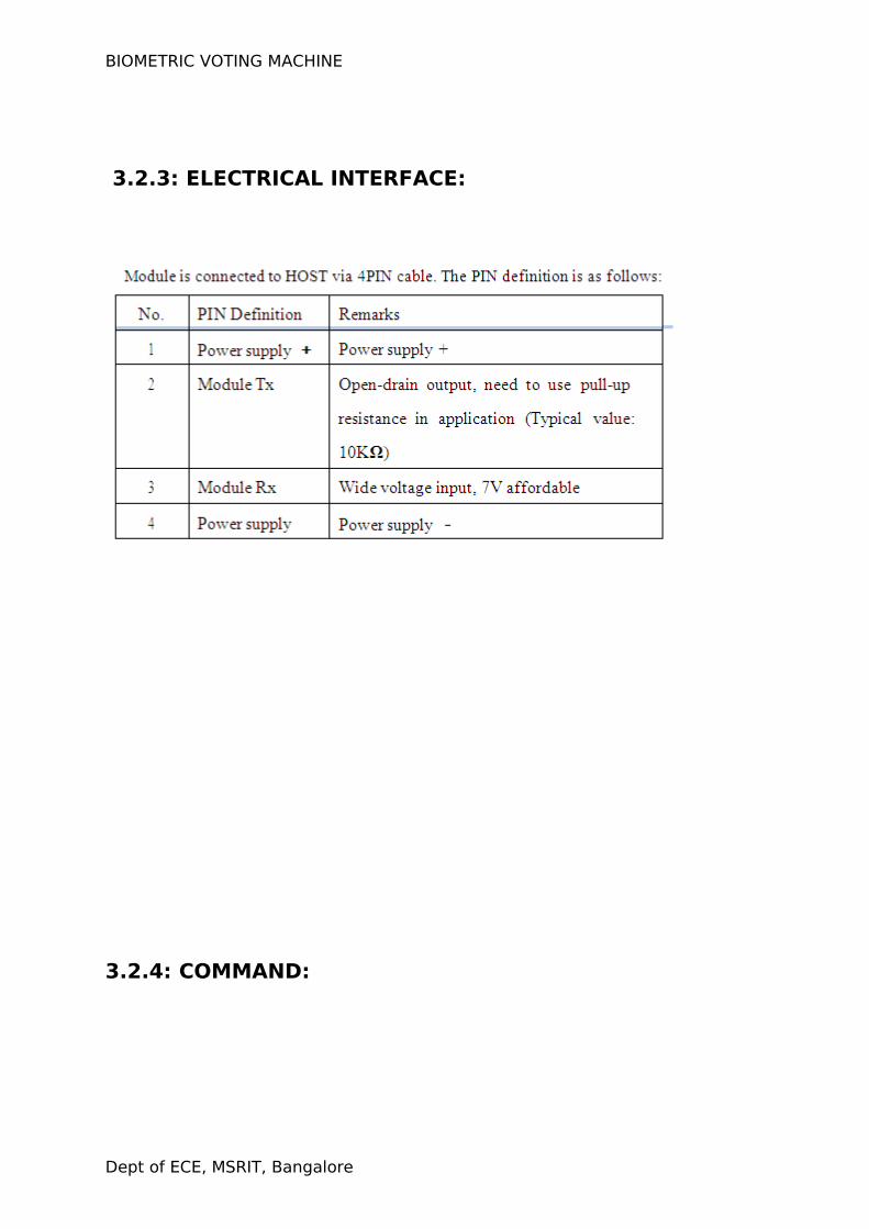
3.2.3: ELECTRICAL INTERFACE:
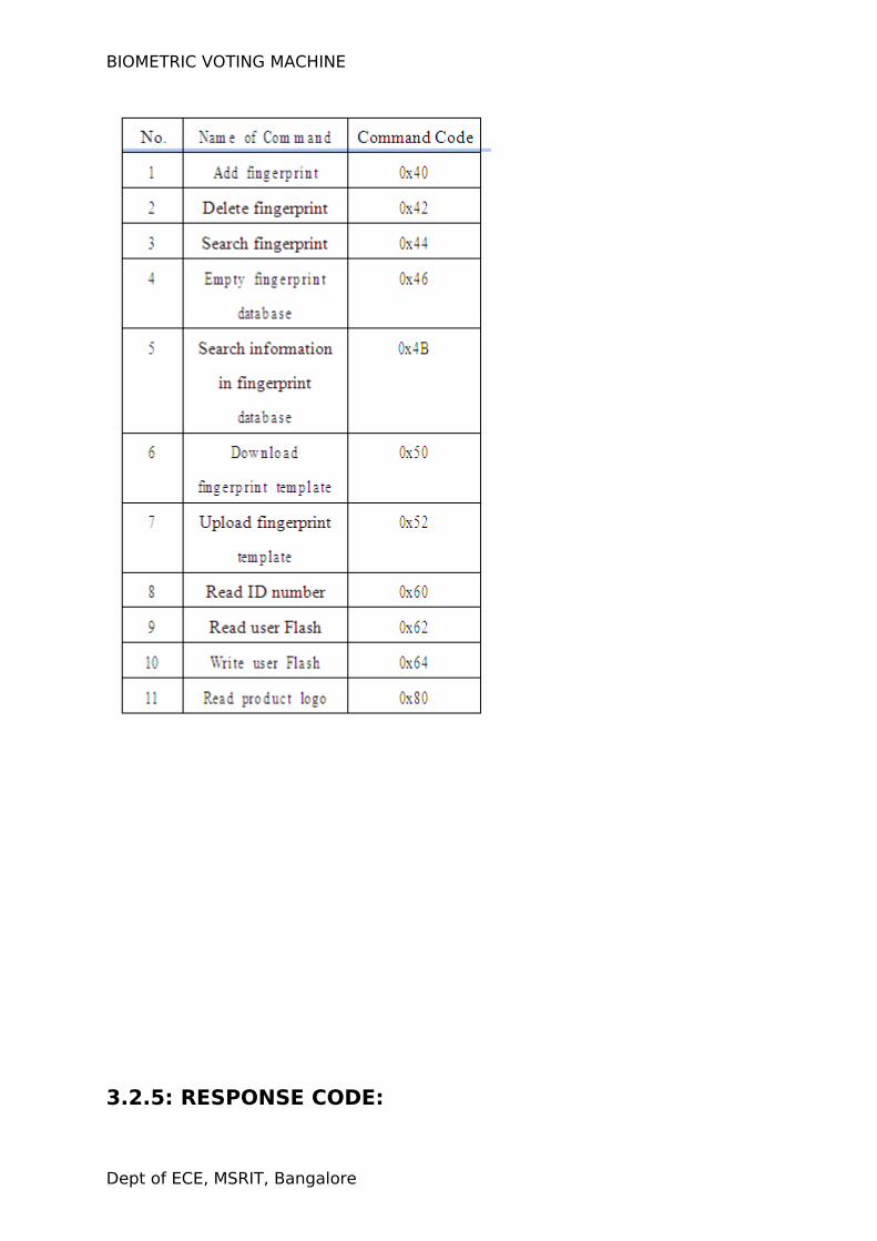
3.2.4: COMMAND:
Dept of ECE, MSRIT, Bangalore
BIOMETRIC VOTING MACHINE
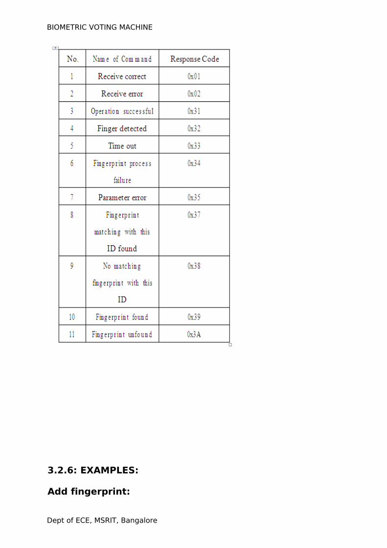
3.2.5: RESPONSE CODE:
Dept of ECE, MSRIT, Bangalore
BIOMETRIC VOTING MACHINE
3.2.6: EXAMPLES:
Add fingerprint:
Dept of ECE, MSRIT, Bangalore
BIOMETRIC VOTING MACHINE
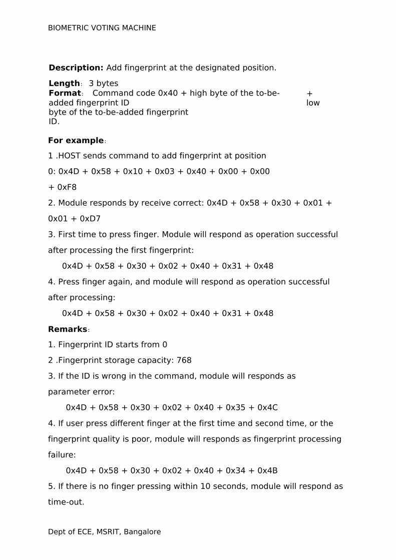
Description: Add fingerprint at the designated position.
Length:3 bytesFormat : Command code 0x40 + high byte of the to-be-added fingerprint ID
+ low
byte of the to-be-added fingerprint ID.
For example:
1 .HOST sends command to add fingerprint at position
0: 0x4D + 0x58 + 0x10 + 0x03 + 0x40 + 0x00 + 0x00
+ 0xF8
2. Module responds by receive correct: 0x4D + 0x58 + 0x30 + 0x01 +
0x01 + 0xD7
3. First time to press finger. Module will respond as operation successful
after processing the first fingerprint:
0x4D + 0x58 + 0x30 + 0x02 + 0x40 + 0x31 + 0x48
4. Press finger again, and module will respond as operation successful
after processing:
0x4D + 0x58 + 0x30 + 0x02 + 0x40 + 0x31 + 0x48
Remarks:
1. Fingerprint ID starts from 0
2 .Fingerprint storage capacity: 768
3. If the ID is wrong in the command, module will responds as
parameter error:
0x4D + 0x58 + 0x30 + 0x02 + 0x40 + 0x35 + 0x4C
4. If user press different finger at the first time and second time, or the
fingerprint quality is poor, module will responds as fingerprint processing
failure:
0x4D + 0x58 + 0x30 + 0x02 + 0x40 + 0x34 + 0x4B
5. If there is no finger pressing within 10 seconds, module will respond as
time-out.
Dept of ECE, MSRIT, Bangalore
BIOMETRIC VOTING MACHINE
0x4D + 0x58 + 0x30 + 0x02 + 0x40 + 0x33 + 0x4A
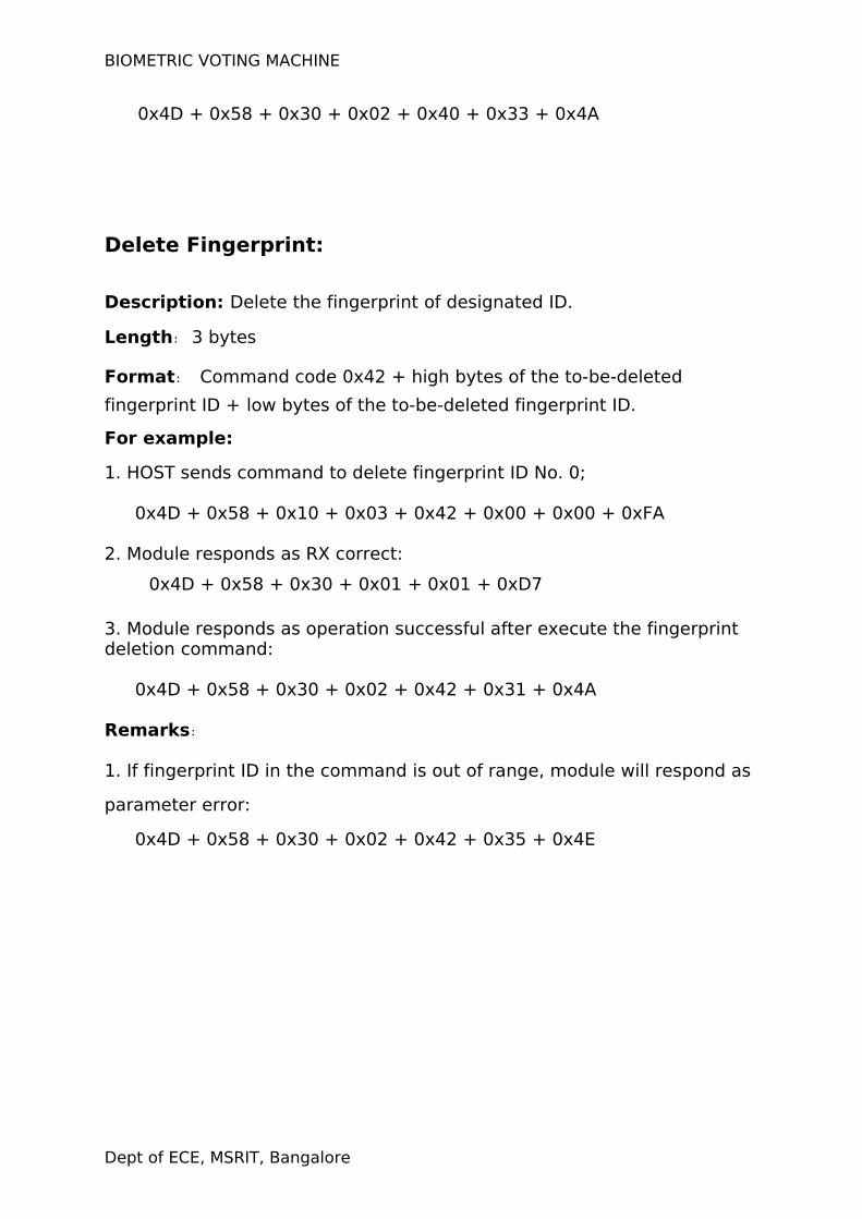
Delete Fingerprint:
Description: Delete the fingerprint of designated ID.
Length:3 bytes
Format : Command code 0x42 + high bytes of the to-be-deleted
fingerprint ID + low bytes of the to-be-deleted fingerprint ID.
For example:
1. HOST sends command to delete fingerprint ID No. 0;
0x4D + 0x58 + 0x10 + 0x03 + 0x42 + 0x00 + 0x00 + 0xFA
2. Module responds as RX correct:
0x4D + 0x58 + 0x30 + 0x01 + 0x01 + 0xD7
3. Module responds as operation successful after execute the fingerprint deletion command:
0x4D + 0x58 + 0x30 + 0x02 + 0x42 + 0x31 + 0x4A
Remarks:
1. If fingerprint ID in the command is out of range, module will respond as
parameter error:
0x4D + 0x58 + 0x30 + 0x02 + 0x42 + 0x35 + 0x4E
Dept of ECE, MSRIT, Bangalore
BIOMETRIC VOTING MACHINE
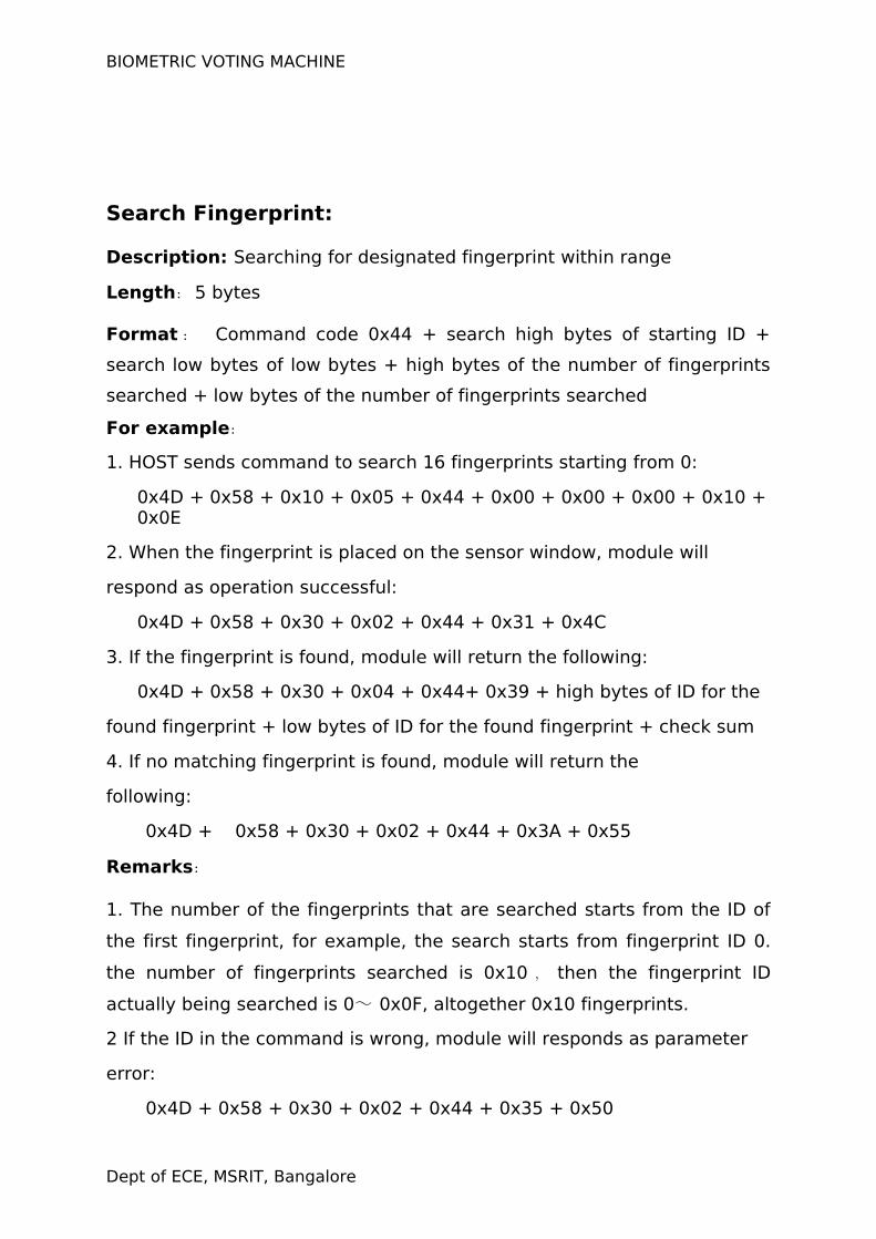
Search Fingerprint:
Description: Searching for designated fingerprint within range
Length:5 bytes
Format : Command code 0x44 + search high bytes of starting ID +
search low bytes of low bytes + high bytes of the number of fingerprints
searched + low bytes of the number of fingerprints searched
For example:
1. HOST sends command to search 16 fingerprints starting from 0:
0x4D + 0x58 + 0x10 + 0x05 + 0x44 + 0x00 + 0x00 + 0x00 + 0x10 + 0x0E
2. When the fingerprint is placed on the sensor window, module will
respond as operation successful:
0x4D + 0x58 + 0x30 + 0x02 + 0x44 + 0x31 + 0x4C
3. If the fingerprint is found, module will return the following:
0x4D + 0x58 + 0x30 + 0x04 + 0x44+ 0x39 + high bytes of ID for the
found fingerprint + low bytes of ID for the found fingerprint + check sum
4. If no matching fingerprint is found, module will return the
following:
0x4D + 0x58 + 0x30 + 0x02 + 0x44 + 0x3A + 0x55
Remarks:
1. The number of the fingerprints that are searched starts from the ID of
the first fingerprint, for example, the search starts from fingerprint ID 0.
the number of fingerprints searched is 0x10 , then the fingerprint ID
actually being searched is 0~ 0x0F, altogether 0x10 fingerprints.
2 If the ID in the command is wrong, module will responds as parameter
error:
0x4D + 0x58 + 0x30 + 0x02 + 0x44 + 0x35 + 0x50
Dept of ECE, MSRIT, Bangalore
BIOMETRIC VOTING MACHINE
3.If the fingerprint quality is poor, module will respond as fingerprint
processing failure:
0x4D + 0x58 + 0x30 + 0x02 + 0x44 + 0x34 + 0x4F
4. If there is no finger placing on the sensor with 10 seconds, module will
respond as time out:
0x4D + 0x58 + 0x30 + 0x02 + 0x44 + 0x33 + 0x4E
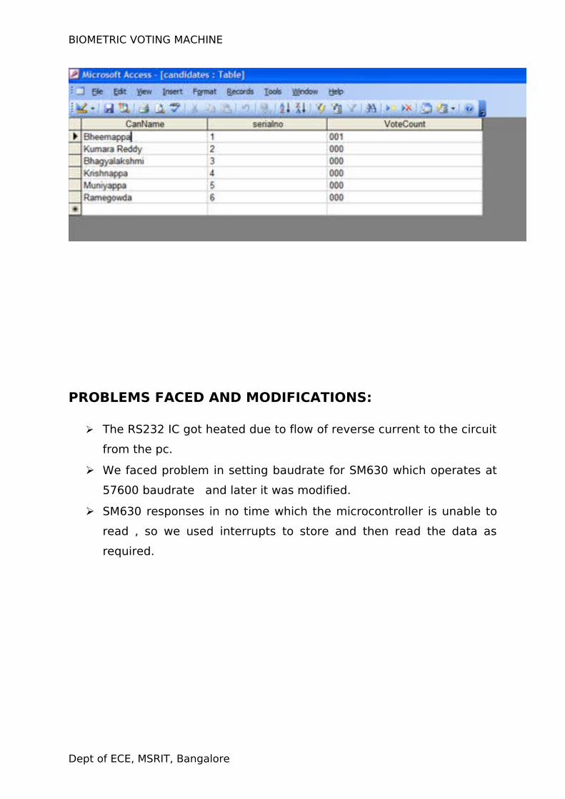
3.3: EEPROM-24C08:
E2PROM became necessary, as we had to store the database
of voters. When an voter votes, the details of the voter, along with the
system time, are stored into the memory chip. Vote obtained for each
candidate is also stored in eeprom. This can be later downloaded to a
computer using the user-friendly front-end software developed in Labview
We use AT24C08 EEPROM having 8K memory and 1 million write
cycle capacity. The AT24C08 provides 8192 bits of serial electrically
erasable and programmable read-only memory (EEPROM) organized as
1024 words of 8 bits each. The device is optimized for use in many
industrial and commercial applications where low-power and low-voltage
operations are essential. This is a serial device, data entering and reading
being serial. The data retention is guaranteed for a 100 years. This is
connected to port pins of microcontroller.
3.4: I2c bus interface:
It makes use of I2C bus interface with microcontroller, which
stands for inter-inter computer communications. The standard was
originally developed by Philips in late 1970s as a method to provide an
interface between microprocessors and peripheral devices without writing
full address, data, and control buses between devices. I2C is the most
efficient and popular serial communication standard. Two wires, serial
data (SDA) and serial clock (SCL), carry information between the devices
connected to the bus. The simple 2-wire serial I2C-bus minimizes
interconnections; so ICs have fewer pins.(AT 24C01 comes in an 8 pin dip
package)
Dept of ECE, MSRIT, Bangalore
BIOMETRIC VOTING MACHINE
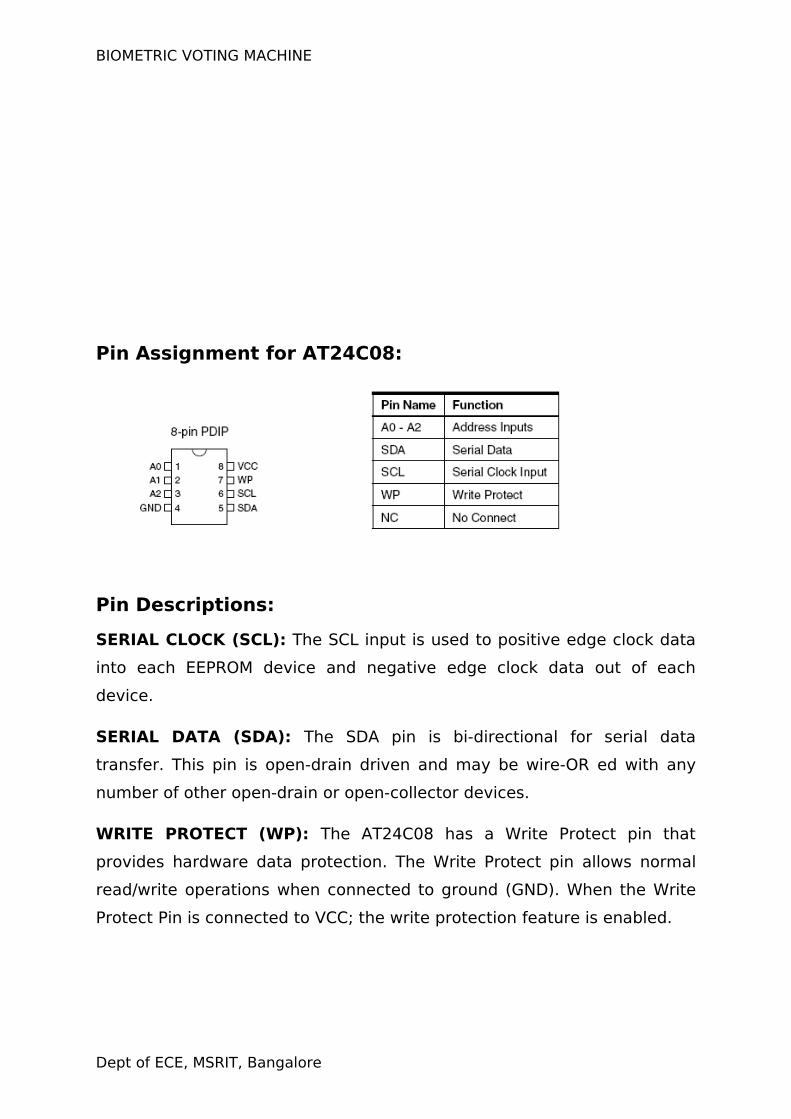
Pin Assignment for AT24C08:
Pin Descriptions:
SERIAL CLOCK (SCL): The SCL input is used to positive edge clock data
into each EEPROM device and negative edge clock data out of each
device.
SERIAL DATA (SDA): The SDA pin is bi-directional for serial data
transfer. This pin is open-drain driven and may be wire-OR ed with any
number of other open-drain or open-collector devices.
WRITE PROTECT (WP): The AT24C08 has a Write Protect pin that
provides hardware data protection. The Write Protect pin allows normal
read/write operations when connected to ground (GND). When the Write
Protect Pin is connected to VCC; the write protection feature is enabled.
Dept of ECE, MSRIT, Bangalore
BIOMETRIC VOTING MACHINE
DEVICE/PAGE ADDRESSES (A2, A1, A0): The AT24C08 only uses the
A2 input for hardwire addressing and a total of two 8K devices may be
addressed on a single bus system. The A0 and A1 pins are no connects.
3.5:LCD DISPLAY- JHD204A:
The LCD display panel is used to display status messages and
error messages. DMC series is the name given to the dot matrix
character LCD display modules that have been developed by
Shenzhen Jing Handa Electronics Co., Ltd.
The modules consist of high contrast and large viewing angle TN
and STN type LC (liquid crystal) panels. Each module contains a CMOS
controller and all necessary drivers which have low power consumption.
The controller is equipped with an internal character generator ROM, RAM
and RAM for display data. All display functions are controllable by
instructions making interfacing practical.
Both display data RAM and character generator RAM can be read
making it possible to use any part not used for display as general data
RAM. The products of this series therefore have wide application
possibilities in the field of terminal display or display for measuring
devices.
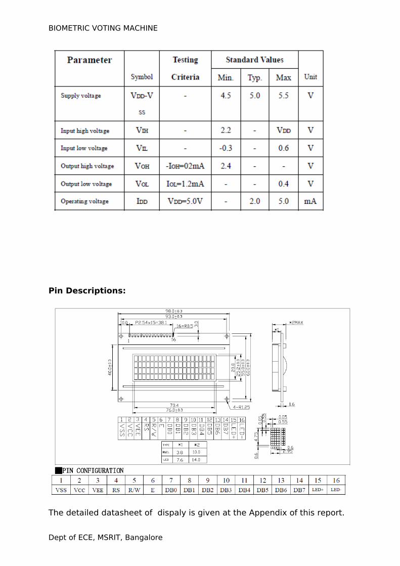
Parameter:
Dept of ECE, MSRIT, Bangalore
BIOMETRIC VOTING MACHINE
Pin Descriptions:
The detailed datasheet of dispaly is given at the Appendix of this report.
Dept of ECE, MSRIT, Bangalore
BIOMETRIC VOTING MACHINE
3.6: SERIAL COMMUNICATION-RS232:
RS-232 is simple, universal, well understood and supported but it
has some serious shortcomings as a data interface. The standards to
256kbps or less and line lengths of 15M (50 ft) or less but today we see
high speed ports on our home PC running very high speeds and with high
quality cable maxim distance has increased greatly. The rule of thumb for
the length a data cable depends on speed of the data, quality of the
cable. Electronic data communications between elements will generally
fall into two broad categories: single-ended and differential. RS232
(single-ended) was introduced in 1962, and despite rumors for its early
demise, has remained widely used through the industry. Independent
channels are established for two-way (full-duplex) communications. The
RS232 signals are represented by voltage levels with respect to a system
common (power / logic ground). The "idle" state (MARK) has the signal
level negative with respect to common, and the "active" state (SPACE)
has the signal level positive with respect to common. RS232 has
numerous handshaking lines (primarily used with modems), and also
specifies a communications protocol.
The RS-232 interface presupposes a common ground between the
DTE and DCE. This is a reasonable assumption when a short cable
connects the DTE to the DCE, but with longer lines and connections
between devices that may be on different electrical busses with different
grounds, this may not be true. RS232 data is bi-polar.... +3 TO +12 volts
indicate an "ON or 0-state (SPACE) condition" while A -3 to -12 volts
indicates an "OFF" 1-state (MARK) condition.... Modern computer
equipment ignores the negative level and accepts a zero voltage level as
the "OFF" state. In fact, the "ON" state may be achieved with lesser
positive potential. This means circuits powered by 5 VDC are capable of
driving RS232 circuits directly, however, the overall range that the RS232
signal may be transmitted/received may be dramatically reduced.
Dept of ECE, MSRIT, Bangalore
BIOMETRIC VOTING MACHINE
The output signal level usually swings between +12V and -12V. The
"dead area" between +3v and -3v is designed to absorb line noise. In the
various RS-232-like definitions this dead area may vary. For instance, the
definition for V.10 has a dead area from +0.3v to -0.3v. Many receivers
designed for RS-232 are sensitive to differentials of 1v or less.This can
cause problems when using pin powered widgets - line drivers,
converters, modems etc. These type of units need enough voltage &
current to power them self's up. Typical UART (the RS-232 I/O chip) allows
up to 50ma per output pin - so if the device needs 70ma to run we would
need to use at least 2 pins for power. Some devices are very efficient and
only require one pin (some times the Transmit or DTR pin) to be high - in
the "SPACE" state while idle.
An RS-232 port can supply only limited power to another device.
The number of output lines, the type of interface driver IC, and the state
of the output lines are important considerations. The types of driver ICs
used in serial ports can be divided into three general categories: Drivers
which require plus (+) and minus (-) voltage power supplies such as the
1488 series of interface integrated circuits. (Most desktop and tower PCs
use this type of driver.) Low power drivers which require one +5 volt
power supply. This type of driver has an internal charge pump for voltage
conversion. (Many industrial microprocessor controls use this type of
driver.)
3.7: KEYPAD:
The system is designed to accommodate five candidates. The key pad used for the system contains five keys and correspondingly five LEDs. There is a special key which is for display total no of vote polled so far.
3.8: POWER SUPPLY:
Power supply unit consists of the following units:
1. Step down transformer
2. Rectifier unit
3. Input filter
Dept of ECE, MSRIT, Bangalore
BIOMETRIC VOTING MACHINE
4. Regulator unit
5. Output filter
STEP DOWN TRANSFORMER: It is used to step down the main supply
voltage by using step down transformer. It consists of primary and
secondary coils. The o/p from the secondary coil is also AC wave form. So
we have to convert the easy wave form into dc voltage by using rectifier
unit.
RECTIFIER UNIT: We have to convert AC voltage to DC using rectifier.
Bridge rectifier is used. This o/p voltage often rectifier is in rippled form,
so we have to remove ripples from DC voltage.
INPUT FILTER: Capacitor acts as filter. The principle of the capacitor is
charging and discharging. It charges in the positive half cycle of the AC
voltage and it will discharge in the negative half cycle. So this allows only
AC voltage and does not allow the DC voltage. This filter is fixed before
the regulator.
REGULATOR UNIT: Regulator regulates the o/p voltage constant
depends on upon the regulator. It is classified as follows.
1. Positive regulator
1. Input pin
2. Ground pin
3. Output pin
It regulates the positive voltage
2. Negative regulator
1. Ground pin
2. input pin
3. output pin
It regulate the negative voltage
OUTPUT FILTER: Capacitor acts as filter. The principle of the capacitor is
charging and discharging. It charges in positive half cycle of the AC
Dept of ECE, MSRIT, Bangalore
BIOMETRIC VOTING MACHINE
voltage an it will discharge in negative half cycle. So it allow only allows
AC voltage and does not allow the DC voltage. This filterer fixed after the
regulator.
Dept of ECE, MSRIT, Bangalore
BIOMETRIC VOTING MACHINE
CHAPTER 4
CIRCUIT DIAGRAM
Dept of ECE, MSRIT, Bangalore
BIOMETRIC VOTING MACHINE
Dept of ECE, MSRIT, Bangalore
BIOMETRIC VOTING MACHINE
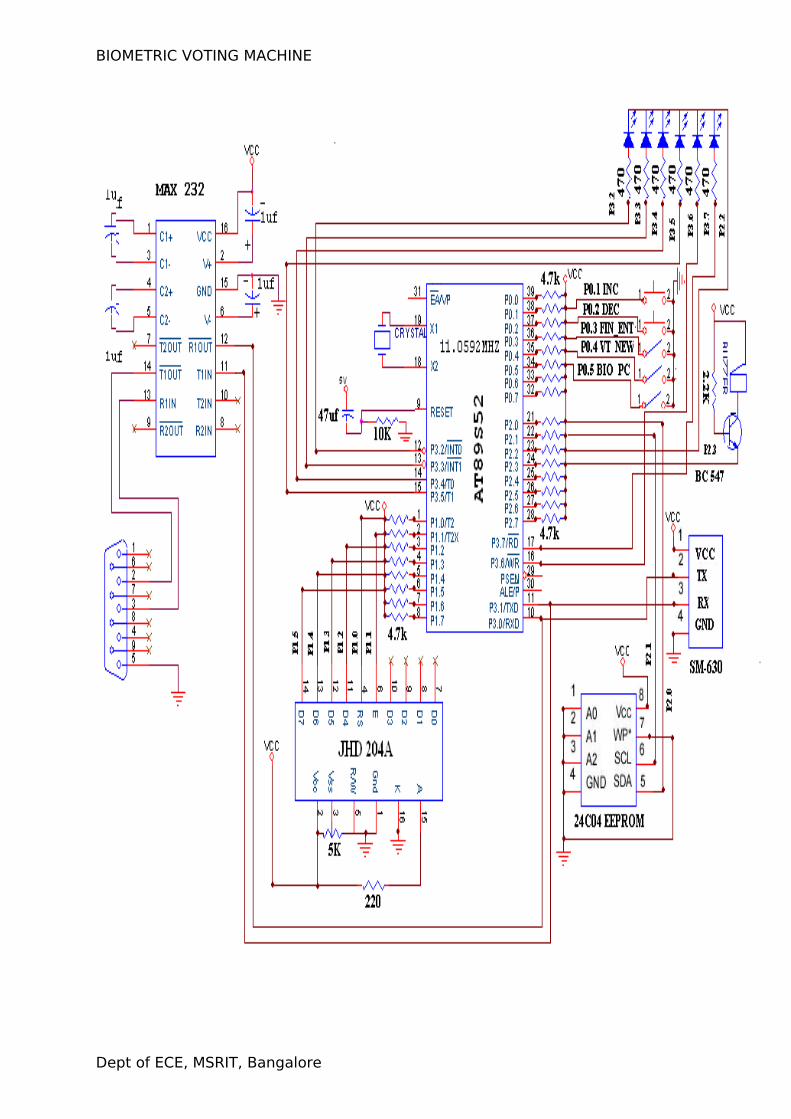
WORKING OF CIRCUIT:
Supply Section of this circuit consists of a 12 volts adaptor, and a IC 7805
IC. The output of the second regulator(IC 7805) is +5 volts, which is used for all
other digital applications.
The voting machine consists of six keys, which are connected to six
separate pins of microcontroller. Port pins P3.2 to P3.7.Which are usually made
high to act as input port and other side of key is connected to P2.2 which acts as
active high input in order to disable the keypad until interrupt occurs.
The display section uses the port 1 of microcontroller. This port is in open
drain configuration and as a result, pull up resistors should be provided for its
normal operation. The contrast of this LCD display is adjusted by changing the
value of a resistor which is grounded at the other end.
A Buzzer is used to indicate whether a voter has exercised his vote
correctly and also for recognizing any malpractice during the whole process. This
buzzer is connected to a supply of +5 volt by means of a pull up resistor.
The EEPROM IC 24C08 is a serial electrically erasable and programmable
read-only memory. It is connected to microcontroller through two pins SDA and
SCL. This EEPROM is used to store the details relating to the voter and indicating
whether a voter has already voted or not and also the date and time of voting.
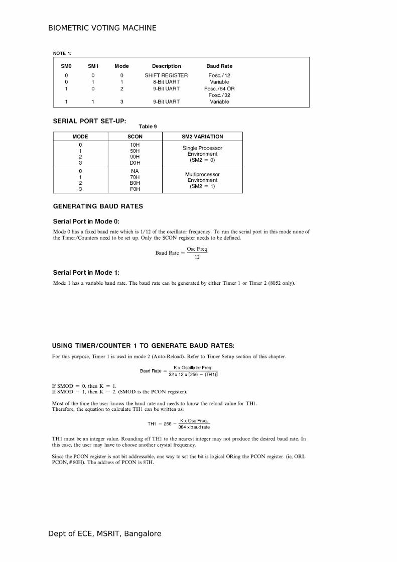
SM630 device operates at 57600 baudrate which is achieved by setting
TH1 and TL1 register to FFH in auto reload mode by which we can achieve
baudrate of 28800 and by setting MSB of PCON register to high we can double
the baudrate to 57600.
SM630 has 4 pins Vcc, gnd ,Tx and Rx.The Tx of SM630 is connected to
serial receive input of microcontroller which is nothing but P3.0 pin. Similarly Rx
of SM630 is connected to serial transmit pin of microcontroller P3.1.
RS-232 which is a simple, universal and well understood standard is
applied in this project. It converts the active high condition of PC(-3 volt to -12
volt) to the active high condition of the microcontroller(+5 volt) and vice versa.
Similarly the active low condition of the microcontroller ( 0 volt) is transformed to
the active low condition of the PC (+3volt to +12volt) and act as a perfect means
Dept of ECE, MSRIT, Bangalore
BIOMETRIC VOTING MACHINE
of interfacing microcontroller and PC.MAX 232 is used in the serial
communication to convert RTL to TTL.
CHAPTER 5
SOFTWARE
Dept of ECE, MSRIT, Bangalore
BIOMETRIC VOTING MACHINE
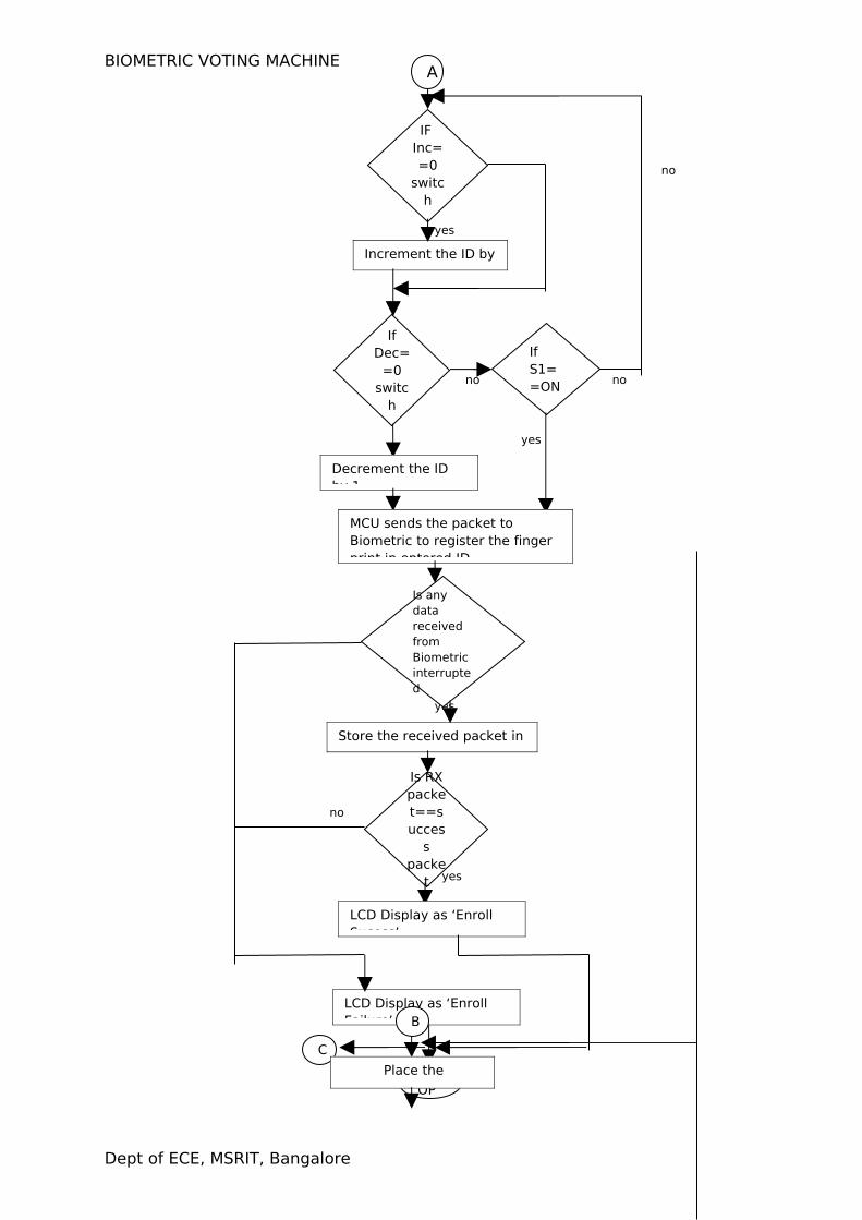
5.1: FLOWCHART
Dept of ECE, MSRIT, Bangalore
BIOMETRIC VOTING MACHINE
No
no
yes
no
yes
no
yes
Dept of ECE, MSRIT, Bangalore
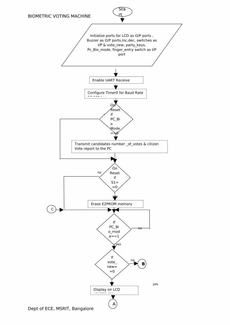
Start
Enable UART Receive
Initialize ports for LCD as O/P ports , Buzzer as O/P ports,Inc,dec, switches as
I/P & vote_new, party_keys, Pc_Bio_mode, finger_entry switch as I/P
port
Configure Timer0 for Baud Rate 57,600 bps
On Reset if PC_Bio Mode==0
Transmit candidates number _of_votes & citizen Vote report to the PC
Erase E2PROM memory locations
If PC_Bio_mode==1
If vote_new=
=0
Display on LCD “ENTER ID”
On Reset
if S1==0
A
B
C
BIOMETRIC VOTING MACHINE
no
yes
no no
yes
no
yes
no
yes yes
Dept of ECE, MSRIT, Bangalore
IF Inc==0
switch
Increment the ID by 1
A
If Dec=
=0 switc
h
If S1==ON
Decrement the ID by 1
MCU sends the packet to Biometric to register the finger print in entered ID
Is any data received from Biometric interrupted
Store the received packet in buffer
Is RX packet==succes
s packe
t
LCD Display as ‘Enroll Sucess’
LCD Display as ‘Enroll Failure’
STOP
C
B
Place the finger
BIOMETRIC VOTING MACHINE
No
Yes
No
Yes
No
Dept of ECE, MSRIT, Bangalore
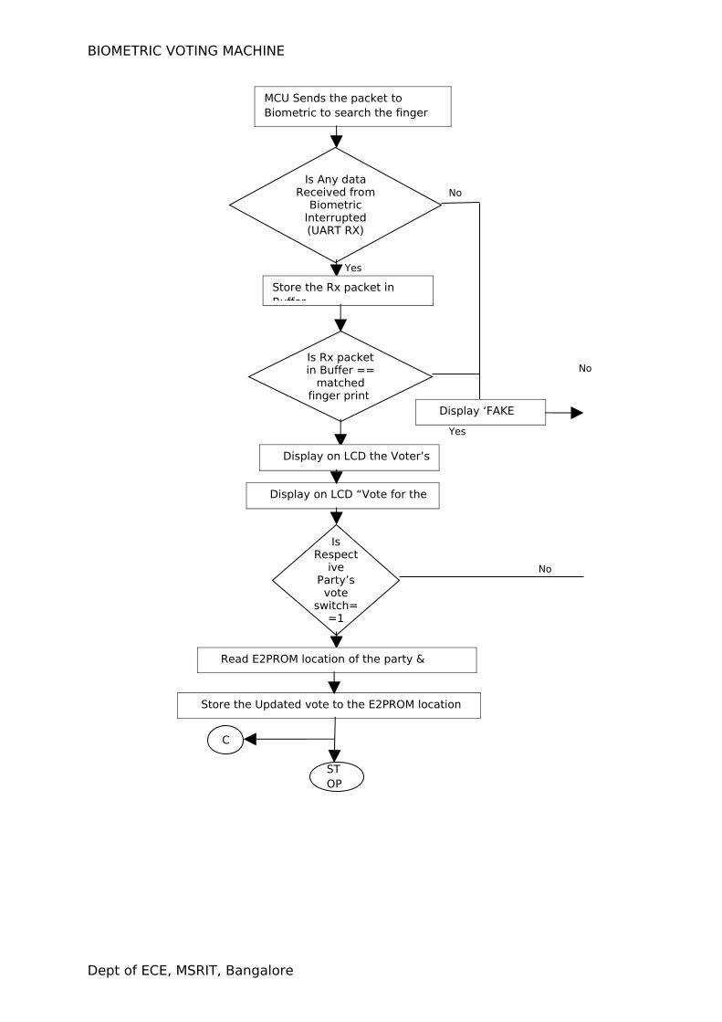
MCU Sends the packet to Biometric to search the finger
Is Any data Received from
Biometric Interrupted(UART RX)
Store the Rx packet in Buffer
Is Rx packet in Buffer ==
matched finger print
Display ‘FAKE VOTER’
Display on LCD the Voter’s ID
Display on LCD “Vote for the party”
Is Respect
ive Party’s vote
switch==1
Read E2PROM location of the party & Increment it by 1
Store the Updated vote to the E2PROM location of the party
STOP
C
BIOMETRIC VOTING MACHINE
FRONT END DESIGN:
Visual Basic (VB) is the third-generation event-driven programming
language and integrated development environment (IDE) from Microsoft
for its COM programming model. Visual Basic is relatively easy to learn
and use.
Visual Basic was derived from BASIC and enables the rapid
application development (RAD) of graphical user interface (GUI)
applications, access to databases using Data Access Objects, Remote
Data Objects, or ActiveX Data Objects, and creation of ActiveX controls
and objects. Scripting languages such as VBA and VBScript are
syntactically similar to Visual Basic, but perform differently.
A programmer can put together an application using the components
provided with Visual Basic itself. Programs written in Visual Basic can also
use the Windows API, but doing so requires external function declarations.
The final release was version 6 in 1998. Microsoft's extended support
ended in March 2008 and the designated successor was Visual Basic .NET
(now known simply as Visual Basic).
Dept of ECE, MSRIT, Bangalore
BIOMETRIC VOTING MACHINE
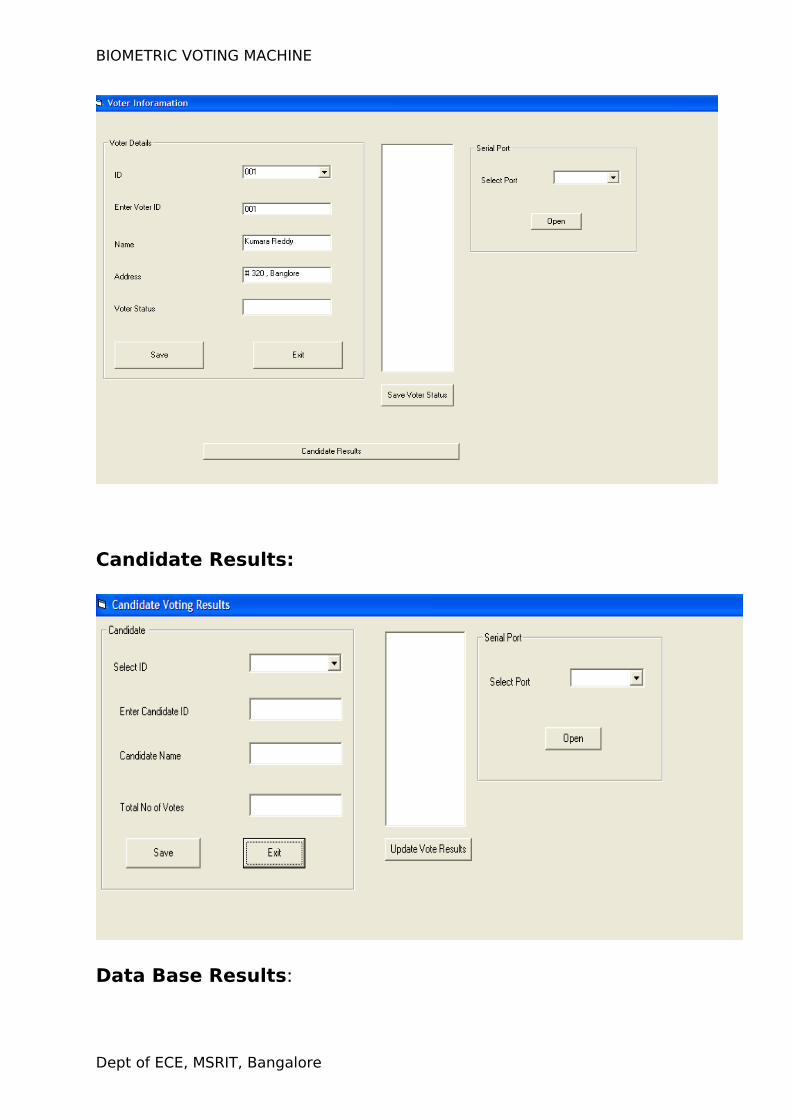
Candidate Results:
Data Base Results:
Dept of ECE, MSRIT, Bangalore
BIOMETRIC VOTING MACHINE
PROBLEMS FACED AND MODIFICATIONS:
The RS232 IC got heated due to flow of reverse current to the circuit
from the pc.
We faced problem in setting baudrate for SM630 which operates at
57600 baudrate and later it was modified.
SM630 responses in no time which the microcontroller is unable to
read , so we used interrupts to store and then read the data as
required.
Dept of ECE, MSRIT, Bangalore
BIOMETRIC VOTING MACHINE
FUTURE MODIFICATIONS:
Memory of finger print module can be expanded .We can use a 1mb
flash memory finger print module for increasing the capacity.
External memory can be provided for storing the finger print image,
which can be later accessed for comparison.
Smart Card reader module is supposed to be introduced with the
existing module for further security, and to reduce the database
storage.
Audio output can be introduced to make it user friendly for illiterate
voters.
Retina scanning can also be developed.
Dept of ECE, MSRIT, Bangalore
BIOMETRIC VOTING MACHINE
APPENDIX
Dept of ECE, MSRIT, Bangalore
BIOMETRIC VOTING MACHINE
Data sheet of 8051(Important parts only):
Dept of ECE, MSRIT, Bangalore
BIOMETRIC VOTING MACHINE
Dept of ECE, MSRIT, Bangalore
BIOMETRIC VOTING MACHINE
Dept of ECE, MSRIT, Bangalore
BIOMETRIC VOTING MACHINE
Dept of ECE, MSRIT, Bangalore
BIOMETRIC VOTING MACHINE
Dept of ECE, MSRIT, Bangalore
BIOMETRIC VOTING MACHINE
Dept of ECE, MSRIT, Bangalore
BIOMETRIC VOTING MACHINE
Dept of ECE, MSRIT, Bangalore
BIOMETRIC VOTING MACHINE
BIBILOGRAPHY
Reference websites:
www.atlmel.com
www.suprema.com
www.8052.com
www. keil .com
Reference books:
1. The 8051 Microcontroller and Embedded Systems, by Ali Mazidi &
Gillispie Mazidi.
2. Embedded Microprocessor Systems: Real World Design by Stuart
R. Ball
3. Interfacing with C, Second Edition by Howard Hutchings and Mike
James
Dept of ECE, MSRIT, Bangalore
Related Documents