KTH/CSC, BGP-MPLS VPN lab, rev: 1.4 KTHNOC BGP-MPLS VPN lab Juniper version Group Nr Name1 Name2 Name3 Name4 Date Grade Instructor’s Signature

Welcome message from author
This document is posted to help you gain knowledge. Please leave a comment to let me know what you think about it! Share it to your friends and learn new things together.
Transcript
KTH/CSC, BGP-MPLS VPN lab, rev: 1.4
KTHNOC
BGP-MPLS VPN lab
Juniper version
Group Nr
Name1
Name2
Name3
Name4
Date
Grade
Instructor’sSignature
KTHNOC, BGP-MPLS VPN lab, rev: 1.4
Table of Contents1 Goals...............................................................................................32 Groups............................................................................................33 Preparations...................................................................................3
3.1Preparation questions...............................................................34 Overview.........................................................................................45 Part 1: The Backbone.....................................................................76 Part 2: L3VPN.................................................................................87 Part 3: L2VPN.................................................................................9
7.1CE configuration.......................................................................97.2PE configuration......................................................................10
8 Cleanup........................................................................................119 References....................................................................................11Appendix A: Netmaps......................................................................12
2
KTHNOC, BGP-MPLS VPN lab, rev: 1.4
1 GoalsThis lab gives an overview of BGP-MPLS provider-based VPNs in the Juniper environment. It handles both L2VPN (virtual private wire service) and L3VPN.
The scenario is the operation of a backbone network configured with MP-BGP, MPLS and RSVP with a set of customers connected to this network. Each customer have several sites, representing their branch-offices. The backbone offers VPN services to the customers, where some customers require L2VPN and some L3VPN.
When the lab is finished, you will understand how L2VPN and L3VPN work, and you will understand how all protocols work together.
2 Groups
The lab includes a common backbone, and the customer sites are distributed among several routers. But the lab can be partitioned into three groups. However, since most of the steps of the lab is based on the whole network it is important to continuously cooperate with the other groups.
The lab requires 20 routers. Each group configures six routers.
3 Preparations
Before you begin this lab, it is essential that you understand BGP-MPLS provider-based VPNs. Read through lecture notes and relevant book chapters, for example Chapter 10 of [2] and Chapter 15 of [4].
The commands used in this lab are best looked up in the JunOS reference manuals[3].
The KTHNOC reference manual[5] can be useful to setup basic IGP, MPLS and RSVP.
3.1 Preparation questions
Preparation questions that should be answered before you come to the lab:
3
KTHNOC, BGP-MPLS VPN lab, rev: 1.4
What is the difference between overlay(customer-based) and peer-to-peer(provider-provisioned) VPNs? ______________________________________________________________________________________
What is a CE?___________________________________________
What is a PE?___________________________________________
What is the purpose of the route distinguisher?___________________________________________
What is the benefit of using type 1 route distinguisher (compared to using type 0)?______________________________________________________________________________________
What is the route target used for?______________________________________________________________________________________
If you configure a full mesh VPN with default import and export route target rules, what command in JunOS can you use instead of import/export rules?______________________________________________________________________________________
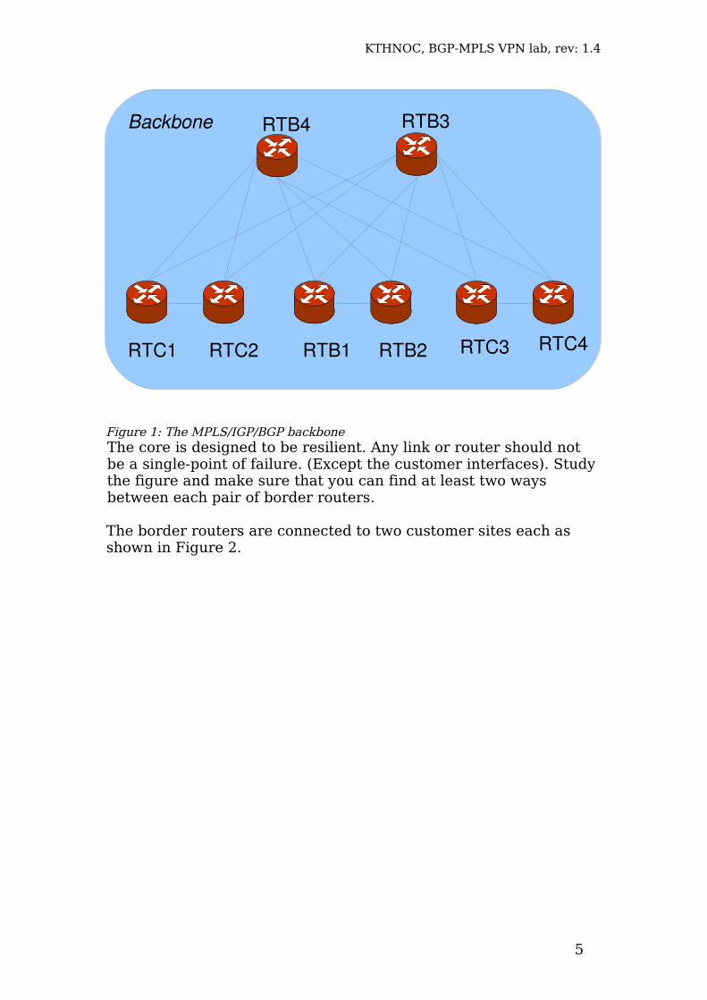
4 OverviewThe lab consists of a backbone as shown in the Figure 1 below. The backbone is a redundant backbone consisting of six border routers, also called PE routers, and two core routers (RTB3 and RTB4), also called P routers. The whole backbone runs an IGP, as well as RSVP and MPLS. The border routers also run BGP, the core routers do not.
4
KTHNOC, BGP-MPLS VPN lab, rev: 1.4
The core is designed to be resilient. Any link or router should not be a single-point of failure. (Except the customer interfaces). Study the figure and make sure that you can find at least two ways between each pair of border routers.
The border routers are connected to two customer sites each as shown in Figure 2.
5
Figure 1: The MPLS/IGP/BGP backbone
RTB4 RTB3
RTB2RTB1RTC1 RTC2 RTC3
Backbone
RTC4
KTHNOC, BGP-MPLS VPN lab, rev: 1.4
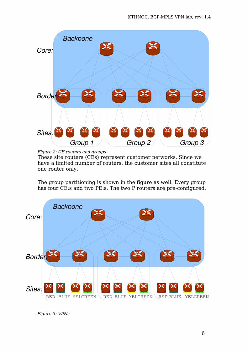
These site routers (CEs) represent customer networks. Since we have a limited number of routers, the customer sites all constitute one router only.
The group partitioning is shown in the figure as well. Every group has four CE:s and two PE:s. The two P routers are pre-configured.
6
Figure 2: CE routers and groups
Backbone
Core:
Border:
Sites:Group 1 Group 2 Group 3
Figure 3: VPNs
BackboneCore:
Border:
Sites:RED RED REDBLUE BLUE BLUEYEL YEL YELGREENGREEN GREEN
KTHNOC, BGP-MPLS VPN lab, rev: 1.4
Figure 3 above shows the VPNs. There four VPNs: RED, BLUE, YEL and GREEN. Each VPN involves three sites, one in each group.
The RED and BLUE VPNs are L2VPN, that is, they are interconnected by pseudowires.
The YEL and GREEN VPNs are L3VPNs, that is, they are interconnected by routing.
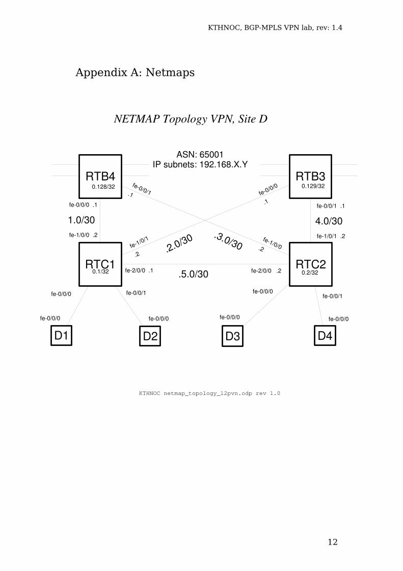
More detailed netmaps are given in Appendix A.
5 Part 1: The Backbone
The two P routers are already configured. Each group should now configure two border routers/PEs according to netmaps 1-3 in Appendix A.
When configuring the backbone, be careful not to configure any dynamic routing protocols on the customer interfaces. Be also very thorough since errors may take a long while to debug in this somewhat complex network.
First, configure all network interfaces, loopback interfaces and router-ids as shown in the netmap. All addresses are in the 192.168.0.0/16 range.
Second, all routers should run an IGP. Configure OSPF and verify that all routers can ping/traceroute all other routers.
Third, the network should run RSVP and MPLS. Configure RSVP and MPLS for all partaking interfaces (ie to the core and to your peer border router) and enable family MPLS on these interfaces as well.
Enable icmp-tunneling for MPLS (so that you can traceroute).
Fourth, setup two LSPs (full mesh) to the other border routers. Set up full mesh between the routers that are necessary (ie RTC1-RTB1-RTC3 and RTC2-RTB2-RTC4). Use the label-switched-path command to setup the LSP. Use the no-cspf option to disable automatic constraint-based routing.
Verify that the LSPs are up. You can do this in several ways. One way is to check RSVP sessions.
Another way is by looking in the inet.3 routing table where RSVP adds its routes by default. Why does RSVP add its routes in inet.3 and not in inet.0?
7
KTHNOC, BGP-MPLS VPN lab, rev: 1.4
_________________________________________________________________________________________________________________________________
Finally set up iBGP. You should use loopback peering and you should setup a full mesh between all border routers. Since we shall run MP-BGP, you should enable two extra address families: l2vpn signalling (for L2VPN) and inet-vpn unicast (for L3VPN)
Verify that the whole backbone works. This is mainly done by examining that the LSPs are in place so that the BGP tables use the LSPs for transit traffic.
Resiliency: Deactivate a backbone interface (where there is an LSP signalled). Study how long it takes before the LSP is reinstalled using an alternate route. Approximately how long does it take? Which protocols are involved?______________________________________________________________________________________
Milestone 1: Show a working backbone.Signature: _____________________
Keep and save the configuration. It will be used as a basis for both the L3VPN and L2VPN parts below.
6 Part 2: L3VPN
You shall now create the YEL and GREEN VPNs.
Start with configuring the CE routers. You should use the last two netmaps in Appendix A, L3VPN #3 and #4.
Configure the interfaces and the extra /24 network. Let eBGP be the PE-CE routing protocol for L3VPN#3 and RIP be the PE-CE routing protocol for L3VPN#4. Export this /24 to the PE-CE routing protocol.
Now configure the PE:s. Create a new routing-instance for each customer. The instance type of the routing instance is “vrf”. Define which interface the VRF attaches, and set the route distinguisher using the RD assigned in the netmap.
Ensure that networks are announced properly from CE:s to PE:s, and from PE:s to CE:s.
8
KTHNOC, BGP-MPLS VPN lab, rev: 1.4
You should also create rules for the route target. Create vrf import and export rules for fully meshed VPNs. Ensure that you export the routes from your customer inet.0 tables – both the /24 customer network and the /30 link network (both are necessary if you want your traceroute to work). A simpler way than to use vrf-import and vrf-export is to use the vrf-target command.
Set also the vrf-table-label command.
Verify that the routing tables look reasonable. Focus first on the customer inet.0 table. After that look at the bgp.l3vpn.0 table to ensure that the VPN routes are exported and imported as they should.
Verify that the VPN works by pinging and trace-routing between the customer sites. Also, try to ping with a large MTU (1500) to verify that all packets sizes work. Check that the routing tables contain the remote networks.
Examine the state of the routers. Write down the name of all routing tables. (There should be at least six) and explain the purpose of each table:________________________________________________________________________________________________________________________________________________________________________________________________________________________________________________________________________________________________________________________________________________________
You may have to wait for some other group before demonstrating the milestone. But you should at least show a working VPN to one other neighbour in both L3VPN#3 (YELLOW) and L3VPN#4(GREEN).
Milestone 2: Show a working L3VPN.Signature: _____________________
Remember to keep the configuration (and save it to disc). You should keep the configuration so that the other groups can use your sites, and save it if you break for the day (you cannot assume that the same configuration will be there next day).
7 Part 3: L2VPNContinue with the L2VPN setup as shown in the L2VPN #1 and #2 in Appendix A. These are the VPNs shown as red and blue in Figure
9
KTHNOC, BGP-MPLS VPN lab, rev: 1.4
3 above. You should be able to use the same backbone as for L3VPN, and the L3VPNs may co-exist with the L2VPNs.
7.1 CE configurationIn these VPNs, we need to create pseudo-wires between each CE. Since it is full mesh, every CE needs to be connected by two pseudo-wires. But since we do not have more than one physical interface (eg fe-0/0/0), we need to create virtual links on the physical Ethernet. This is done by creating VLANs.
On the CE and PE, create two VLANs on the interconnecting Ethernet link. This is made by configuring vlan-tagging on the top-level, and then creating one unit for each VLAN. In each unit configure a vlan-id as used in Appendix 2. Within the unit, also configure an address.
Example of one VLAN configured on fe-0/0/0interfaces{
fe0/0/0 {vlantagging;unit 935 {
vlanid 935;family inet {
address 193.2.4.5/24}
}}
}
No further configuration is necessary on the CE:s.
7.2 PE configurationThe PE configuration is more elaborate. First, the access interfaces should be configured with matching VLANs from the customer. Encapsulation vlan-ccc should also be configured on the physical interface, which determines how the encapsulation within the pseudo-wire is achieved. No IP address should be configured on the customer interface. Why not?______________________________________________________________________________________
Then, a routing instance for each L2VPN is created as follows:1. The routing instance is of type l2vpn2. The route distinguisher is assigned. Use loopback address:
VPN number as before.3. Use full mesh vrf targets (vrf-target command using 65001:#)4. Define the sites (below)
10
KTHNOC, BGP-MPLS VPN lab, rev: 1.4
The sites and their interconnection is made within the protocol l2vpn clause. It is essentially made by virtually interconnecting the L2VPN sites manually. First the local site is defined and an identifier is assigned to it. Then, the pseudo-wires to the remote sides are defined. It is recommended to use the naming proposed by the netmap in Appendix A, that is, use the last number in the router-id as site number.
Ensure that you have a working setup. It should be possible to ping between the CE:s.
Examine the state of the routers. Write down the name of all routing tables. How do they differ from L3VPN?________________________________________________________________________________________________________________________________________________________________________________________________________________________________________________________________________________________________________________________________________________________
Milestone 3: Show a working L2VPN.Signature: _____________________
8 CleanupTo reset the machines to their initial state, follow the following steps for all routers.
1. Reset the configuration by loading (using override) the ~root/labconf configuration.
9 References
[1] KTHNOC Router lab Introduction - Juniper version[2] White. McPehrson and Sangli, “Practical BGP”, Addison-Wesley[3] JunOS 8.2 routing configuration guide http://www.juniper.net/techpubs/software/junos/junos82/swconfig82-routing/html [4] Garrett, “JunOS Cookbook”, O'Reilly[5] KTHNOC Router lab Reference - Juniper version
11
KTHNOC, BGP-MPLS VPN lab, rev: 1.4
Appendix A: Netmaps
12
NETMAP Topology VPN, Site D
KTHNOC netmap_topology_l2pvn.odp rev 1.0
RTB3
fe0/0/0 .1
fe2/0/0 .1 fe2/0/0 .2.5.0/30
.2.0/30fe1/0/0 .2
1.0/30
fe1/0/1
.2
fe0/0/0
.1
fe0/0/1.1
fe1/0/0.2
fe0/0/1 .1
fe1/0/1 .2
4.0/30
RTB4
.3.0/30
fe0/0/0
RTC2RTC1
D4D3D2D1
fe0/0/1 fe0/0/0 fe0/0/1
fe0/0/0 fe0/0/0 fe0/0/0 fe0/0/0
0.128/32 0.129/32
0.2/320.1/32
ASN: 65001IP subnets: 192.168.X.Y
KTHNOC, BGP-MPLS VPN lab, rev: 1.4
13
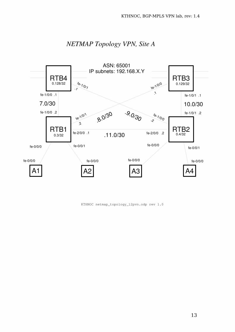
NETMAP Topology VPN, Site A
KTHNOC netmap_topology_l2pvn.odp rev 1.0
RTB3
fe1/0/0 .1
fe2/0/0 .1 fe2/0/0 .2.11.0/30
.8.0/30fe1/0/0 .2
7.0/30
fe1/0/1
.2
fe1/0/0
.1
fe1/0/1.1
fe1/0/0.2
fe1/0/1 .1
fe1/0/1 .2
10.0/30
RTB4
.9.0/30
fe0/0/0
RTB2RTB1
A4A3A2A1
fe0/0/1 fe0/0/0 fe0/0/1
fe0/0/0 fe0/0/0 fe0/0/0 fe0/0/0
0.128/32 0.129/32
0.4/320.3/32
ASN: 65001IP subnets: 192.168.X.Y
KTHNOC, BGP-MPLS VPN lab, rev: 1.4
14
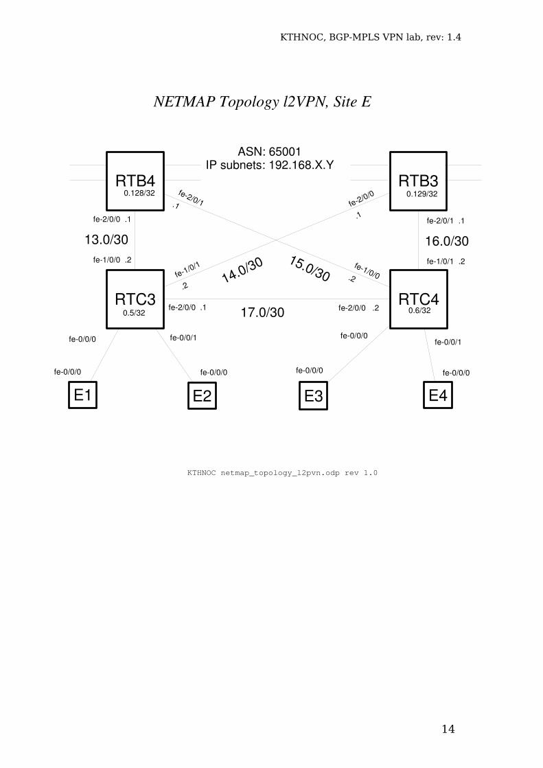
NETMAP Topology l2VPN, Site E
KTHNOC netmap_topology_l2pvn.odp rev 1.0
RTB3
fe2/0/0 .1
fe2/0/0 .1 fe2/0/0 .217.0/30
14.0/30fe1/0/0 .2
13.0/30
fe1/0/1
.2
fe2/0/0
.1
fe2/0/1.1
fe1/0/0.2
fe2/0/1 .1
fe1/0/1 .2
16.0/30
RTB4
15.0/30
fe0/0/0
RTC4RTC3
E4E3E2E1
fe0/0/1 fe0/0/0 fe0/0/1
fe0/0/0 fe0/0/0 fe0/0/0 fe0/0/0
0.128/32 0.129/32
0.6/32
ASN: 65001IP subnets: 192.168.X.Y
0.5/32
KTHNOC, BGP-MPLS VPN lab, rev: 1.4
15
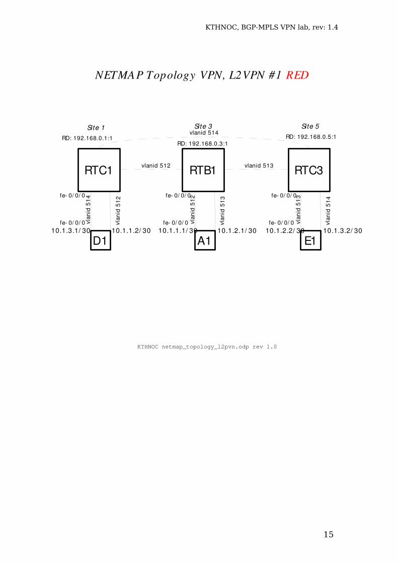
NETMAP Topology VPN, L2VPN #1 RED
KTHNOC netmap_topology_l2pvn.odp rev 1.0
vlan
id 5
13
RTB1
A1
vlan
id 5
12
vlan
id 5
12
D1
vlan
id 5
14
RTC1
vlan
id 5
14
E1
vlan
id 5
13
RTC3
vlanid 514
vlanid 512 vlanid 513
10.1.1.2/ 30 10.1.1.1/ 3010.1.3.1/ 30 10.1.3.2/ 3010.1.2.1/ 30 10.1.2.2/ 30
fe 0/ 0/ 0 fe 0/ 0/ 0 fe 0/ 0/ 0
Site 1 Site 3 Site 5
fe 0/ 0/ 0 fe 0/ 0/ 0 fe 0/ 0/ 0
RD: 192.168.0.1:1RD: 192.168.0.3:1
RD: 192.168.0.5:1
KTHNOC, BGP-MPLS VPN lab, rev: 1.4
16
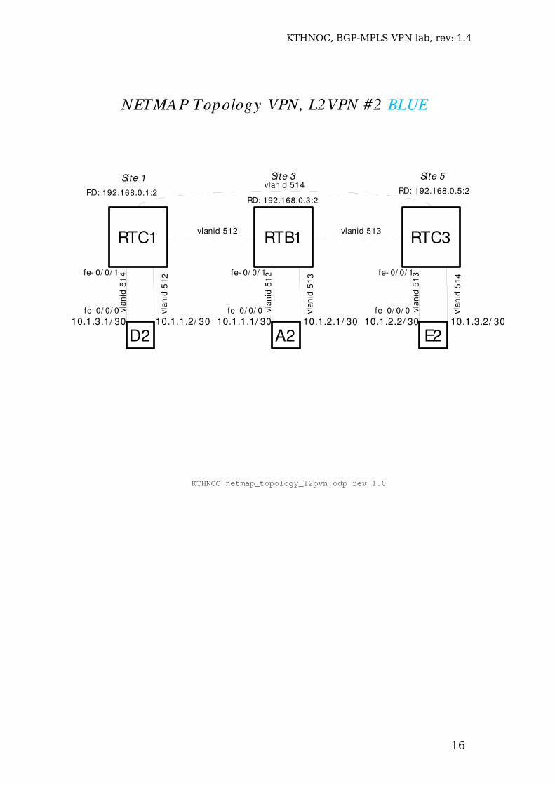
NETMAP Topology VPN, L2VPN #2 BLUE
KTHNOC netmap_topology_l2pvn.odp rev 1.0
vlan
id 5
13
RTB1
A2
vlan
id 5
12
vlan
id 5
12
D2
vlan
id 5
14
RTC1
vlan
id 5
14
E2
vlan
id 5
13
RTC3
vlanid 514
vlanid 512 vlanid 513
10.1.1.2/ 30 10.1.1.1/ 3010.1.3.1/ 30 10.1.3.2/ 3010.1.2.1/ 30 10.1.2.2/ 30
fe 0/ 0/ 1 fe 0/ 0/ 1 fe 0/ 0/ 1
Site 1 Site 3 Site 5
fe 0/ 0/ 0 fe 0/ 0/ 0 fe 0/ 0/ 0
RD: 192.168.0.1:2RD: 192.168.0.3:2
RD: 192.168.0.5:2
KTHNOC, BGP-MPLS VPN lab, rev: 1.4
17
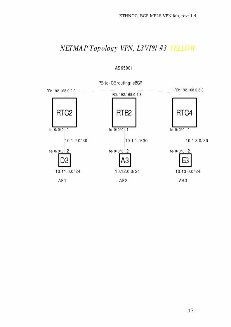
NETMAP Topology VPN, L3VPN #3 YELLOW
RTB2
A3D3
RTC2
E3
RTC4
10.1.2.0/ 30
fe 0/ 0/ 0
fe 0/ 0/ 0 .2
.1
10.1.1.0/ 30 10.1.3.0/ 30
fe 0/ 0/ 0
fe 0/ 0/ 0 .2
.1 fe 0/ 0/ 0
fe 0/ 0/ 0 .2
.1
10.11.0.0/ 24 10.12.0.0/ 24 10.13.0.0/ 24
PE to CE rout ing: eBGP
RD: 192.168.0.2:3RD: 192.168.0.4:3
RD: 192.168.0.6:3
AS 65001
AS 1 AS 2 AS 3
KTHNOC, BGP-MPLS VPN lab, rev: 1.4
18
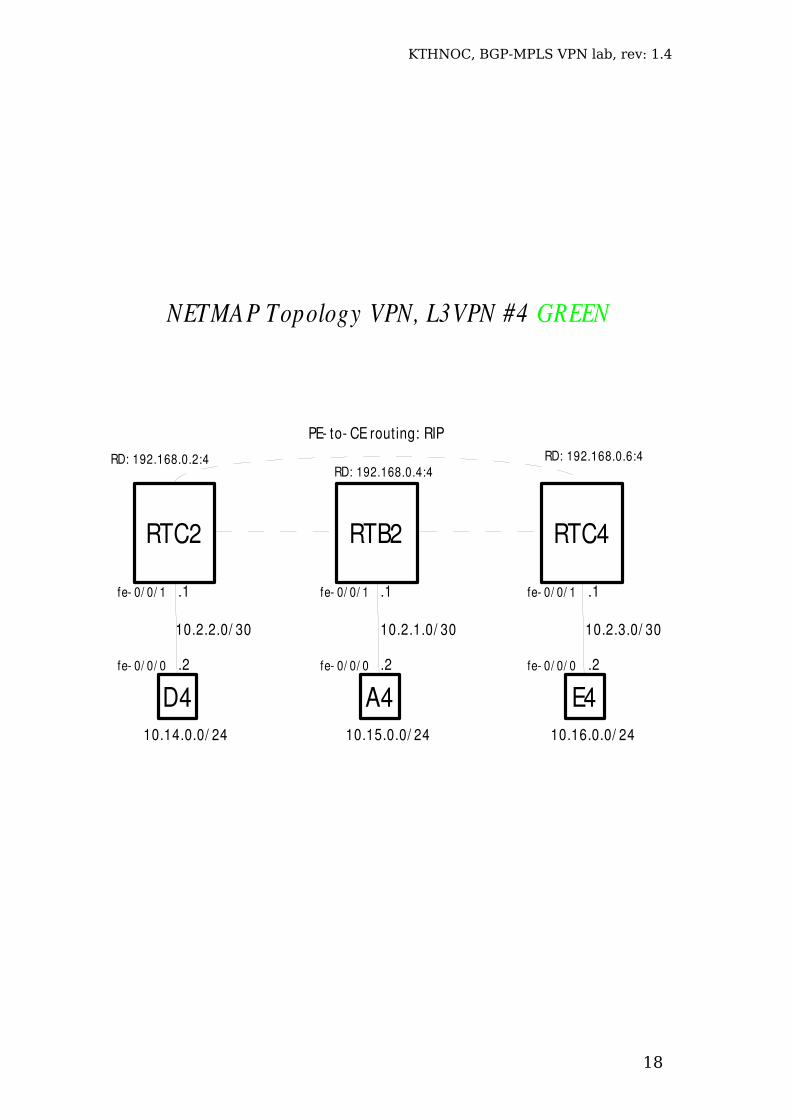
NETMAP Topology VPN, L3VPN #4 GREEN
RTB2
A4D4
RTC2
E4
RTC4
10.2.2.0/ 30
fe 0/ 0/ 1
fe 0/ 0/ 0 .2
.1
10.2.1.0/ 30 10.2.3.0/ 30
fe 0/ 0/ 1
fe 0/ 0/ 0 .2
.1 fe 0/ 0/ 1
fe 0/ 0/ 0 .2
.1
10.14.0.0/ 24 10.15.0.0/ 24 10.16.0.0/ 24
PE to CE routing: RIP
RD: 192.168.0.2:4RD: 192.168.0.4:4
RD: 192.168.0.6:4
Related Documents